EP0962824A2 - Optimizing workflow in a prepress printing system - Google Patents
Optimizing workflow in a prepress printing system Download PDFInfo
- Publication number
- EP0962824A2 EP0962824A2 EP99201030A EP99201030A EP0962824A2 EP 0962824 A2 EP0962824 A2 EP 0962824A2 EP 99201030 A EP99201030 A EP 99201030A EP 99201030 A EP99201030 A EP 99201030A EP 0962824 A2 EP0962824 A2 EP 0962824A2
- Authority
- EP
- European Patent Office
- Prior art keywords
- job
- image receiving
- receiving substrate
- image
- drum
- Prior art date
- Legal status (The legal status is an assumption and is not a legal conclusion. Google has not performed a legal analysis and makes no representation as to the accuracy of the status listed.)
- Granted
Links
Images


Classifications
-
- G—PHYSICS
- G06—COMPUTING; CALCULATING OR COUNTING
- G06K—GRAPHICAL DATA READING; PRESENTATION OF DATA; RECORD CARRIERS; HANDLING RECORD CARRIERS
- G06K15/00—Arrangements for producing a permanent visual presentation of the output data, e.g. computer output printers
-
- B—PERFORMING OPERATIONS; TRANSPORTING
- B41—PRINTING; LINING MACHINES; TYPEWRITERS; STAMPS
- B41B—MACHINES OR ACCESSORIES FOR MAKING, SETTING, OR DISTRIBUTING TYPE; TYPE; PHOTOGRAPHIC OR PHOTOELECTRIC COMPOSING DEVICES
- B41B21/00—Common details of photographic composing machines of the kinds covered in groups B41B17/00 and B41B19/00
- B41B21/32—Film carriers; Film-conveying or positioning devices
-
- G—PHYSICS
- G06—COMPUTING; CALCULATING OR COUNTING
- G06K—GRAPHICAL DATA READING; PRESENTATION OF DATA; RECORD CARRIERS; HANDLING RECORD CARRIERS
- G06K15/00—Arrangements for producing a permanent visual presentation of the output data, e.g. computer output printers
- G06K15/02—Arrangements for producing a permanent visual presentation of the output data, e.g. computer output printers using printers
-
- H—ELECTRICITY
- H04—ELECTRIC COMMUNICATION TECHNIQUE
- H04N—PICTORIAL COMMUNICATION, e.g. TELEVISION
- H04N1/00—Scanning, transmission or reproduction of documents or the like, e.g. facsimile transmission; Details thereof
- H04N1/387—Composing, repositioning or otherwise geometrically modifying originals
- H04N1/3872—Repositioning or masking
-
- G—PHYSICS
- G06—COMPUTING; CALCULATING OR COUNTING
- G06K—GRAPHICAL DATA READING; PRESENTATION OF DATA; RECORD CARRIERS; HANDLING RECORD CARRIERS
- G06K2215/00—Arrangements for producing a permanent visual presentation of the output data
- G06K2215/0002—Handling the output data
- G06K2215/0062—Handling the output data combining generic and host data, e.g. filling a raster
- G06K2215/0065—Page or partial page composition
-
- G—PHYSICS
- G06—COMPUTING; CALCULATING OR COUNTING
- G06K—GRAPHICAL DATA READING; PRESENTATION OF DATA; RECORD CARRIERS; HANDLING RECORD CARRIERS
- G06K2215/00—Arrangements for producing a permanent visual presentation of the output data
- G06K2215/0002—Handling the output data
- G06K2215/0062—Handling the output data combining generic and host data, e.g. filling a raster
- G06K2215/0071—Post-treatment of the composed image, e.g. compression, rotation
Definitions
- the invention relates generally to imagesetting and electronic prepress systems and methods for enhancing system workflow. More particularly, the present invention is directed towards automated systems and methods for optimizing the workflow in a prepress system.
- a selected output device such as an imagesetter, printer or platesetter
- a dedicated raster image processor RIP
- front-end a front-end computer
- Electronic prepress image data file sizes are often greater than 100 megabits per page, and the large file requirements have historically restricted electronic prepress systems to dedicated proprietary hardware and software systems which use parallel data transfer methods to provide high speed data transfer rates between the front-end, the RIP and the output device
- the RIP is said to "rasterize" a PDL image file by performing operations such as image screening, color separating, imposition, trapping and various other prepress image preparation operations upon the PDL image data to yield raster image data in bitmap format.
- the raster image data is then transferred to the output device over a parallel data transfer interface in order to provide an efficient data transfer rate, thereby, keeping the output device operating at a desired operating speed.
- the process of rasterizing or RIPing data has been slow, sometimes causing the output device to remain idle while waiting for a RIP to prepare the next bitmap image file.
- the 8 bit data is transferred over parallel data interface cables which provide a plurality of separate wires bundled together, each transmitting data in parallel.
- parallel data transfer methods are restricted to one way data transfer, e.g. between the RIP and MUX or between the MUX or RIP and an output device
- a serial data channel has also been provided bundled within, or in addition to, the parallel data interface cable to provide two way communication for protocol and other message or file communication between the RIP and the MUX or between the RIP or MUX and the output device or between the front-end and the RIP, the MUX or the output device.
- One significant drawback of a parallel data transfer interface has been that the cable length is limited in order to maintain efficient and effective data transfer.
- cable length may be limited to about 25 feet requiring that the RIP, MUX and output device each be locally connected to each other and usually all within the same room.
- This shortcoming of the prior art has limited prepress systems to local connectivity and slowed the development of automation features needed in modern prepress workflow environments.
- Features such as job queuing, equipment swapping, and manipulating, editing, storing and transferring previously RIPed bitmap image data are needed in the modern prepress environment.
- a need also exists to provide a digital proofing device capable of providing either a color or black and white proof of the final image since films which used to provide analog proofs have often been eliminated from the prepress workflow.
- Such proofing systems may accept image files as page description data, screened bitmap data or bitmap data which has not been screened.
- a need therefore exists to redirect image data to a proofer, and that data may need to be prepared in an appropriate format for output by the proofer.
- a print job (hereinafter a "job") required that a specific output device be connected to the system before the job could be processed.
- a job requiring a particular imagesetter for an output device, or a particular medium type or size loaded onto the output device, could not be processed into raster data if the particular output device and corresponding media requirements were not met.
- Such a condition may cause a system delay or require that a front-end operator physically change the medium or output device connected to the RIP in order to continue processing and outputting image files.
- front-end operators are kept busy by controlling the transfer of bitmap image data between a RIP and a MUX. Burdening these operators with control of the output process reduces overall system efficiency. By moving control of the RIPing and image output process to a system administrator, the front end operator and the front-end itself become free to function more efficiently.
- One shortcoming of electronic prepress systems of the prior art has been the inability to automatically control and monitor the queuing of output jobs and to make changes in the order or priority of image output either from the RIP of from the output device.
- Another shortcoming is the lack of efficiency in a computer-to-plate system which is caused by inactive components.
- Another shortcoming is the inability to accommodate different size image receiving substrates when burning an image.
- Yet another shortcoming is the inability to adequately mark a plate during printing without marring the image in order to provide real-time identification information such as the identify of a job, a time stamp indicating when the job is completed, an operator identifier, a print engine identifier, a customer identification number, user defined graphics, etc.
- a method for automatically processing a job in a prepress printing environment includes the steps of: moving an image receiving substrate from a storage bin to a staging area; moving the image receiving substrate from the staging area into a drum; imaging a predefined area of the image receiving substrate in the drum with a laser while simultaneously moving a next image receiving substrate from the storage bin to the staging area; upon completion of the imaging of the image receiving substrate in the drum, simultaneously (a) moving the image receiving substrate from the drum into a processing area for developing an image on the image receiving substrate, and (b) moving the next image receiving substrate from the staging area into the drum; and finally repeating the above steps until the job is completed.
- the method optionally includes: offsetting the position of the image receiving substrate to alter the location upon the image receiving substrate where the image will be burned; or offsetting the laser position to alter the location upon the image receiving substrate where the image will be burned.
- a slug line can also be printed at print time outside of the predefined area, and can include identifying information such as a job name, a print drive job identification, a time stamp, a plane name, a page number and user-defined graphics.
- APIS Agfa Print Engine Interface is a proprietary point to point data transmission protocol consisting of a serial bi-directional command channel (APIS serial) and a parallel uni-directional data channel (APIS video).
- Device API Generic Application Programming Interface for output devices.
- Engine A hardware device capable of receiving and printing raster image data on film or other media.
- An output printing device Also referred to as "print engine”.
- Fast Ethernet (100 BaseT) Communication medium 100 Mb/sec maximum transfers over twisted pair wire.
- File Storage for one separation, i.e. each separation or plane of a job is stored in its own file.
- GUI Graphical User Interface which most broadly represents all the hardware, software and firmware necessary to implement interaction between the computer system and the user.
- Job Control Server The print drive subsystem that controls access to the print drive Job List and job entries on the list.
- Job List This is a user created list of jobs to be imaged, i.e. printed, under the control of the print drive system.
- Job State Current read-only State of a Job. (E.g., Hold, Imaging, Spooling, etc.).
- MUX Multiplexer Page One or more related separations together constitute a "page”. For example, the cyan, magenta, yellow, and black separations for page 3.
- Pickable Job A job which passes all the user defined criteria checks.
- Print drive configuration server The print drive subsystem that controls print drive client access to the Windows NT registry section for the print drive. Registry Place in NT where static information about installed software is held. RIP Raster image processor. This device RIPS or rasterizes object-oriented PDF files into bitmapped raster data. SCSI Small Computer System Interface is a standard high-speed parallel interface defined by the X3T9.2 committee of the American National Standards Institute (ANSI). Used for connecting microcomputers to peripheral devices, other computers and local area networks. Separation A single 1-bit raster image as output from a RIP. A separation is an image representation of a single color channel. For example, "the cyan separation”. This is also referred to as a "plane". One separation is stored in a file. Spindle Choice of media holding device for use on an engine. Spooling Inputting a job.
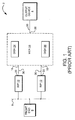
- Figure 1 illustrates a prior art prepress system, referred to generally by reference numeral 2 comprising an output device 4, at least one computer terminal or front-end 6, for creating, editing or otherwise preparing image data for printing and especially halftone black and white or color printing as may be output by an imagesetter or platesetter for eventual image reproduction by a printing press using a printing plate.
- the front-end 6 is connected via a network serial data interface 8 to two raster image processors 10 and 12.
- the RIPs 10 and 12 receive, from the front-end 6, image data which is typically in the form of a page description language or other object oriented text and graphic representation of the image to be printed.
- a multiplexer 14 includes two input ports 16 and 18 connected to the output ports 20 and 22 of the RIPs 10 and 12, respectively.
- Two large format disk drives 24 and 26 act as image data buffers which are included in the MUX 14 for storing image data.
- the primary purpose of the MUX 14 is to function as a page buffer for the output device 4.
- a MUX output port 28 connects with the output device 4.
- all data transferred from the RIP output ports 20 and 22 to the MUX 14, or from the MUX 14 to the output device 4, or within the MUX 14 to the disk drives 24 and 26 has been converted to bitmap raster data. The data transfer has been made over parallel data transfer cables 30.
- the shortcomings of the prior art have included the inability to manage the RIPing and outputting functions of the prepress process by a system administrator and the costly proprietary hardware with few, but costly, expansion opportunities provided for the prepress customer.
- FIG. 2 is a block diagram of a preferred hardware embodiment of a prepress system including one or more print drives in which the job selection method can be implemented.
- the various components of the prepress system 32 are preferably interconnected via a fast Ethernet network 35 utilizing TCP/IP data transfer protocol.
- the prepress system 32 is configured for controlling RIPing and output workflow and for providing more flexible operating and expansion options to the prepress customer.
- This prepress system 32 includes: one or more RIPs 34; one or more front-ends 40; one or more print drives 41; one or more servers 42 for storing image and other data files; one or more proofers 43 or other output devices 44 (such as a printer); and another computer system 45 which may be used for system administration.
- Each of the above and any other added network components may be either locally or remotely interconnected.
- One or more output devices 59 are connected to the print drives 41.
- the output devices 59 may include any output devices which are used in a prepress system or in a printing environment, such as a printer, a print engine, a proofer, a filmsetter, an imagesetter, a platemaker or a computer-to-plate system.
- the output device 59 generates raster bitmap image data representing halftone or otherwise screened images for eventual transfer onto a film 70 or a printing plate 72 for reproduction by a printing press (not shown).
- Such output devices 59 may require proprietary or non-proprietary serial or parallel image data transfer from the print drives 41 of may require descreened bitmap data when the output device is a proofer 43, for providing a continuous tone proof of the image to be reproduced.
- the RIPs 34 may be software RIPs or they may be dedicated hardware RIPs, such the Agfa StarTM hardware RIP available from Bayer Corporation, Agfa Division in Wilmington, Massachusetts. Each RIP 34 appears on the fast Ethernet network 35 and can be accessed by any front-end 40, server 42, print drive 41 or other computer system 45, any of which may by either local or remote.
- Each front-end 40, server 42, print drive 41 and other computer 45 is essentially a separate computer system each operating preferably on Windows NTTM, although any available operating system can be used, such as a UNIXTM or a MAC OSTM.
- An IBM PCTM or clone could be used for a print drive 41.
- Each RIP 34 includes a data compression module for compressing bitmap data.
- the compression module facilitates the use of serial bitmap data transfer over the fast Ethernet network 35, instead of parallel bitmap data transfer, by substantially compressing files to a size which allows for serial data transfer.
- the compression module compresses RIPed data which can be transferred either directly, or over the network 35, to one or more output devices 59 or to one or more print drivers 41.
- each RIP 34 includes both a fast Ethernet interface board which facilitates transfer of the compressed data via TCP/IP protocol, and a data decompression board for decompressing the compressed data
- the print drive 41 which is essentially a special purpose computer, operates on a standard computer platform such as Windows NTTM configured for efficient print driving functions.
- the print drive hardware includes: a central processing unit such as a 200 mhz Pentium processor 76; sufficient random access memory (RAM) 75 for running the operating system and the various applications programs of the print drive 41; a data buffer 80 for temporary data storage of image data being transferred between the print drive and other prepress system components, and for temporary data storage of data being transferred between components within the print drive 41; one or more SCSI disks or other high capacity hard drives 55; a SCSI controller 53 for providing access to and from the SCSI disk 55; a decompression board 51 for decompressing compressed image data files stored in the disk 55 or received via the data buffer 80; a fast Ethernet board 50 for facilitating transfer of data over the fast Ethernet 35 by ensuring that data is formatted according to the well known TCP/IP protocol; a video board 78 for facilitating transfer of graphical data to a monitor for observation by a system
- the output board 54 may include a proprietary or standard data transfer protocol adapter module for interfacing with output devices 59.
- a preferred protocol is the Agfa Print Engine Interface Specification (APIS) which is a proprietary point-to-point data transmission protocol consisting of a serial bi-directional command channel and a parallel video uni-directional data channel.
- APIIS Agfa Print Engine Interface Specification
- Each graphical user interface typically includes a monitor, keyboard and mouse for user interaction with the print drives 41.
- the tuner GUI 60 controls the configuration and operation of the print drive 41 and is based upon standard Windows NTTM technology.
- the pilot GUI 62 is directed to provide an interactive link between the front-end users, typically MACTM and PCTM networked users, and the print drive operator, typically a system administrator or prepress shop manager.
- the tuner GUI 60 is run locally on the print drive 41.
- the pilot GUI 62 is preferably run remotely but can be run locally if desired.
- the preferred remote GUI pilot 62 may reside in the front-ends 40 or other terminals, e.g. in computer 45, and it is designed to accommodate a number of different user interface types, such as those used on a MACTM or a PCTM.
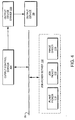
- FIG 4 is a block diagram of a preferred output architecture for job control in the prepress printing system of Figure 2.
- the fast Ethernet network 35 links each of the components together.
- the architecture includes an output control server 104, an output device driver 106, an output device 59 and a job picker server 100.
- the job picker server 100 includes a plane picker 110, a job picker 112 and a job order estimator 114.
- the output control server 104 is a print drive 41 component which uses the job picker 112.
- the job picker server 100 provides three software routines. The first is a job picker routine 112 for selecting a next job for printing from a predefined list of jobs. The second is a plane picker routine 110 for selecting a next plane for printing from a predefined list of available planes. And the third is a job order estimator routine 114 which estimates the order in which jobs will be printed. Each of theses software routines is dependent upon a list of processing criteria to be described hereinafter.
- the output control server 104 is a print drive 41 component which uses the job picker routine 112 to select the next job for printing, and uses the plane picker routine 110 to select the next plane within that picked job for printing.
- a preferred system design allows for the operator of the tuner GUI 60, which is local to and controls the print drive 41, to independently use the job order estimator routine 114 to display the estimated order of imageable jobs, that is, pickable jobs which the job picker routine 112 can send to the output device 59.
- the processing criteria used as a basis for selecting a job, selecting a plane or estimating the order in which jobs will print, include preferences such as:
- a criterion i.e. a preference, passes the criteria check when the specific condition of the criterion is met.
- the job picker 112 selects, based first on the priority preference and then (if two or more jobs have the same priority) on the creation time, the next imageable job, i.e. the next job to be printed.
- the output control server 104 can use the job picker 112 to select and return planes in the selected job for imaging.
- a GUI application can retrieve and display the estimated order of printing pickable jobs from the job list.
- the output control server 104 uses the job picker 112 to select the next best job to image on an output device 59. After a next job is selected, the output control 104 makes use of the plane picker routine 110 to get each individual separation of the selected job. If desired, a GUI application could allow the user to get the estimated order in which jobs will be printed by calling a get picker list software program. When this routine is called, the job picker 112 checks all jobs in the current job list and returns a list of jobs which meets the defined criteria.
- the print drive configuration includes a generic application programming interface (API) for output devices.
- API application programming interface
- the job control server 104 controls access to the job list information.
- the job picker routine 112 maintains a local copy of preferences or job selection criteria, which are read from the print drive area of the Windows NTTM registry. These preference values are read via the print drive API and stored into memory. Whenever a preference is changed by the user, a notification is sent to retrieve the changed value from the NT Registry.
- the job picker routine 112 interfaces both directly and indirectly to the following print drive components: output control; configuration server API; engine manager class; and image condition manager class.
- Output control calls the job picker routine 112 to get the next job for imaging to the connected device.
- the output control calls the job picker routine 112 it passes a list of media status objects which must include a print drive medium name and a flag specifying whether the required medium is loaded onto the print engine.
- the job identification of the picked job, and the status of the medium to be used with the picked job are returned from the job picker routine 112.
- the job picker routine 112 uses the engine manager class after it has determined the best job to pick. It is called to validate the job to make sure it will physically fit on the connected engine's medium and, to make sure that the picked job is still present on the job list. The engine manager validates the job.
- the job picker routine also interfaces to one of the image condition manager methods. This is used by the Picker Checks routine for checking image conditions. It specifically determines if a particular image condition is enabled.
- the job picker 112 contains interfaces that are setup and used at the time the job picker 112 is actually initiated by the output control server 104.
- the various interfaces include an engine manager class interface, art observer interface and an image condition manager interface.
- the job picker routine 112 initiates an interface or class called the Engine Manager. This class is used by several different print drive components for different reasons. The job picker routine 112 uses this class for job validation.
- the preference values are derived from an observer class or interface that allows the reception of notifications when certain events occur in the print drive system 41.
- the job picker routine 112 will attach, e.g. sign up for notification, to the print drive configuration API via its subject. This effectively causes the job picker routine 112 to be notified whenever the user modifies the settings of one or more preferences.
- the job picker routine 112 can then update its local preferences by re-reading them via the print drive configuration server API.
- the job picker routine 112 initiates an Image Condition Manager interface during initialization. This interface is used internally by the job picker routine 112 to update a cache of image conditions that are read via the print drive configuration server API. The methods of the Image Condition Manager are available for usage by the job picker routine 112.
- the job picker routine 112 effectively generates a job profile for each job located on a predefined job list by applying predefined criteria, then selecting a next job to be processed from the job list by comparing the job profiles.
- the print drive operator can input preference information for a new job via the tuner GUI 60.
- the preference information may include:
- the output preference specifies whether the job can be printed immediately after the first separation is input, or whether the whole job must be input before printing can begin.
- the priority preference such as urgent, high, normal or low, allows the user to create or modify the priority of a job. Other priorities could be used, if desired. Jobs that do not meet the priority preference are not allowed to print.
- the priority preference in the preferred embodiment takes precedence over all other preferences other than creation time and date. For example, if two jobs at different priorities are eligible to output, the higher priority job is picked first. However, if two jobs with identical priority preferences are eligible for output, then the job with the earliest creation time and date will print first.
- the image condition preference is unique from the other preferences by enabling jobs to print which are contingent upon a particular condition precedent. These conditions can vary from customer to customer and are defined via the tuner GUI 60. For example, the operator may wish to defer printing of a particular job Z until after jobs A, D and G have been printed.
- Other image condition preferences include, but are not limited to, printing:
- the operator also must select a particular print engine by its engine name, and a particular type and size of medium for the job to be pickable.
- Other preferences could be easily added to the routine if desired, such as an operator name, a customer name, a product name, a customer prioritization number, the time and date of creation of a new job, the maximum deferral preference, etc.
- the maximum deferral preference is used by the job picker routine 112 after all jobs on the job list have been checked to see if they are pickable or not. All pickable jobs are associated with a particular available medium. When the available medium is actually loaded on the output device, the medium is considered selected.
- the job picker routine 112 When the job picker routine 112 is determining the next best job to image, it considers if the medium associated with the job is currently selected. When the medium is not currently selected, the job picker routine 112 can defer having the output device load the correct medium. The routine 112 will defer jobs that need a different medium selected and increment the current deferral count. When this deferral count is equal to the maximum deferral preference, the job picker is then allowed to pick a job that will need a new medium to be selected.
- the purpose for the maximum deferral preference is to allow the user to tune his or her system so that the output device will not be constantly loading a different medium on every job that is picked by the job picker routine 112. The media unloading and loading operations on an output device can be very time consuming.
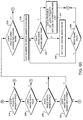
- Figures 6A, 6B and 6C are flowchart diagrams of a preferred job selection method implemented by the job picker software 112 loaded into the print drive 41 for picking a next job for printing.
- the preferred method is actually a two pass procedure although a single or multiple pass variation of the same method could yield the same results.
- the first pass as illustrated in Figures 6A and 6B makes a list of all pickable jobs and the second pass illustrated in Figure 6C picks the next job to print from the list of pickable jobs.
- the job picker routine 112 calls a common private Picker Check routine which reads the current job list, via the output control server 104, into the data buffer 80. The first pass uses this locally stored job list.
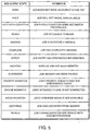
- the processing criteria used as a basis for selecting a job, selecting a plane or estimating the order in which jobs will be printed includes the above criteria or preferences. Additionally, the output and input states of the job are considered. Typical job output states are queued in Figure 5. The three possible input job states are "complete", "incomplete” or "error". An input job state of complete is realized when all the required preferences have been logged to allow a job to be pickable and when the image to be printed has been completely acquired or spooled into memory. If the required preferences have not been logged, or if the job has not been completely spooled, then the input state is considered to be incomplete.
- a picker check subroutine is called from the job picker routine 112 to read the information associated with each job and check the information against the specified preferences. Each check is performed in sequence and if any checks fail to meet the criteria, the job is ineligible to be picked. See Figure 5 for a listing of the output states.
- the job list is retrieved in block 202 of Figure 6A.
- a job is selected from the job list and block 206 determines if the job list is empty. If the job list is empty, then the first pass for finding all pickable jobs is complete and no jobs are pickable. If the job list is not empty, then the current job output state (see Figure 5) is checked in block 210. If the current job has been completed, i.e. printing is complete, or if the output state is in error, then another job is retrieved from a list in block 204. Otherwise, if the current job is incomplete, then the job input state is tested in block 212.
- block 214 tests if the input state of the current job is spooling. If the current job is not spooling, then another job is retrieved in block 204. Otherwise, block 216 tests if the output preference is to print after a single separation is received, or after the whole job is received. If the output preference is to print the whole job, then another job is retrieved in block 204. Otherwise, block 218 tests if the input state of the current separation is spooling. If the current separation is spooling, then another job is retrieved in block 204. Otherwise, block 220 tests if the current separation's input state is complete and the current separation's output state is incomplete.
- block 224 in Figure 6B tests the current job's priority against the priority preference. If the job's priority is less than the priority preference, then another job is retrieved in block 204. Otherwise, block 228 tests for a conditional hold. If a job's image condition is an unconditional hold, then another job is retrieved in block 204. Otherwise, block 230 tests if the current job has no image condition. If true, then the method continues to block 236. Otherwise, block 232 determines if the image condition preference has been enabled. For instance, if the job is slated for printing during third shift, is that condition enabled. If not, then another job is selected in block 204.
- block 236 determines whether the job's engine name matches a connected engine name. If not, then another job is retrieved in block 204. Otherwise, a list of available media names are retrieved in block 238. Block 242 tests if the current job's medium name matches a media available on the named connected engine. If not, the next medium name is retrieved in block 246 from the media list. If the medium name is valid in block 248, then the routine loops back to block 242. Otherwise, another job is retrieved in block 204. If the current job's medium name matches the name of the media available on the named connected engine, then the current job is pickable and added to the sorted job picker list in block 244. Thereafter another job is retrieved in block 204.
- the job picker's second pass consists of actually picking the next job to image.
- the pickable jobs that are highest in priority are always picked before lower priority jobs. Priority always takes precedence over any other criteria, except creation time and date. If two jobs both are urgent priority, then the job with the earlier creation time and date will be selected as the next job to be printed. Jobs are selected off the lists in the priority order of urgent, high, normal and low. A list is skipped if there are no job entries on it. Alternatively, if a single new job list is created rather than four new priority job lists, that new single list would order the jobs thereon by priority.
- the second pass of the job picker routine 112 is outlined in Figure 6C. If no jobs are pickable as tested in block 250, then the routine returns that finding in block 252. Otherwise, a job is retrieved from the highest priority second pass job list in block 254. If the second pass job list is not empty when tested in block 256, then print priority from that list is established by the job having the earliest creation time and date. These parameters are tested in block 258, as well as the maximum deferral preference.
- the job picker routine 112 stores the engine media that are currently loaded and available for immediate printing on the print engine.
- a job on a second pass job list is picked if the job's intended medium is available on the engine. Otherwise, the current deferral is checked against the maximum deferral preference. If the maximum deferral value has not been reached, then the job is skipped and its output state is marked as Deferred. When the maximum deferral preference has been reached, the current deferral value is reset and the first job (on that second pass job list) which was deferred is picked as the job to image. Otherwise, the job identification number and medium name are returned in block 262. If there are not enough jobs on the second pass job list to reach the maximum deferral value, then the first job which was deferred on that list is returned as the next job to image.
- block 260 tests if the job medium name matches the medium loaded on the connected engine. If true, then block 262 returns the job identification and medium name. Otherwise, block 266 tests if the current deferral matches the maximum deferral. If true, then the current deferral is reset and the first job which was deferred is removed from that second pass job list. Otherwise, the current deferral is incremented in block 268, and the routine loops back to block 254 where another job is retrieved from the highest priority list. If no more jobs are listed on the highest priority list, then a job is retrieved from the second highest priority list, etc.
- a validation routine is called which makes sure that the selected job for printing next is still valid to image on the currently connected engine. This check ensures that the job will fit on the engine's selected medium and also that the job is still present on the selected second pass job list. If the picked job is invalid, its output state is marked as invalid and the second pass of the job picker processes again.
- the plane picker routine 110 provides a way for the output control server 104 to retrieve the next plane, i.e. the next image separation. There are three uses for this routine.
- the first case above is actually the way the job picker routine 112 checks an output state to determine if a job is ready to be imaged when the image condition preference is set to image immediately after the first separation is received.
- the main usage of this routine is by the output control server 104 to fetch the next image file for printing.
- the plane picker routine 110 interfaces to both the output control server 104 and the job picker routine 112. As was previously described, the plane picker routine 110 can be used in several different ways. All callers must pass a job identification and a file name. The plane picker routine 110 will return a pointer to an image file class upon successfully finding the next plane to image, or it will return a null pointer if it fails to find a next plane to image.
- Figure 7 is a flow chart diagram of one preferred implementation 300 of the plane picker routine 110.
- block 302 if the Collation job parameter is turned on, then the process continues in block 306. If the Collation job parameter is turned off, then the page number and plane name are cleared in block 304. An image file containing the data for a given image separation is retrieved from a selected spooled job in block 306. If the file is empty in decision block 308, then a null result is returned in block 320. Otherwise, the file input and output states are determined in block 310. If the page number of the job is 0 as determined in decision block 312, then the process continues at block 322. Otherwise, block 314 tests whether the input state is complete AND the output state is incomplete AND the number of copies to be printed is greater than 0. If true, then the image file is returned in block 316. Otherwise, block 318 tests whether the file input state is spooling. If true, then a null result is returned in block 320. Otherwise, the process continues in block 306.
- Block 322 tests whether the page and plane name are found. If true, then the process continues in block 326. Otherwise, the process continues in block 324. Block 324 tests whether the current page equals the input page AND the current plane equals the input plane. If true, then the plane name is retrieved in block 328. Otherwise, the process continues in block 306.
- Block 326 tests if the file input state is complete AND if the number of copies is greater than zero AND if the file output state is either complete or none. If these conditions are true, then the current plane is returned in block 330. Otherwise, the process continues in block 306.
- plane picker routine 110 follows the steps of the above-described job picker routine 112.
- process steps are essentially the same as those in the job picker routine except that the comparisons are made between separation or plane profiles to determine which separation should be the next separation to be printed, rather than between job profiles to determine which job should be the next job to be printed.
- the job order estimator routine 114 can be used by a GUI application to retrieve a snapshot of the pickable jobs currently on a job list, and to generate an estimated order in which jobs will be printed, subject to the existing criteria.
- the ordered image list is estimated, since jobs entering the system, a change of preferences, or a change in conditions can drastically change the list order in short notice.
- This job order estimator routine 114 makes use of the common private method, picker checks, which reads the current job list into a local buffer.
- the routine 114 operates in exactly the same manner as the first pass of the job picker routine 112. After the pickable jobs are found, the routine 114 copies the job identification numbers into order of printing priority.
- the job order estimator routine 114 interfaces both directly and indirectly to the following print drive components: configuration server API; engine manager class; and image condition manager class. These components were previously described in conjunction with the job picker routine 112.
- FIG 8 is a diagram of the Agfa GalileoTM digital platesetter for use with the prepress printing system of Figure 2.
- a plate or image receiving substrate is automatically retrieved from a storage bin and sent to a drum for imaging.
- a laser burns an image onto the plate, then sends the plate to a processor for chemically developing the image.
- a second plate is retrieved from the storage bin and sent to the drum for imaging.
- a plate 410 is transferred from a bin 400 to the staging area 402, then to the drum 404 for imaging. While the plate is being burned in the drum 404, a next plate is retrieved from the bin 400 and sent to the staging area 402 where it awaits the completion of the imaging of the plate 410 within the drum 404.
- This early preparation is referred to as plate overlapping in the system workflow.
- the burned plate 410 is simultaneously extracted from the drum while the next plate 410 is sent from the staging area 402 into the drum 404. In this way, valuable time is saved and the efficiency of the platesetter 59 is improved.
- Figure 8 illustrates that each stage of the platesetter is being utilized throughout the platemaking process for ultimate efficiency. Note that there are plates 410 in the bins 400, a plate 410 in the staging area 402, a plate 410 being imaged in the drum 404, a plate 410 in the chemical developing bath 406, and a plate 410 in the output area 408.
- a computer-to-plate device such as the Agfa GalileoTM includes multiple mutually exclusive stages, i.e. preparing a plate for input, imaging a plate, and processing a plate, all of which can occur concurrently.
- Plate preparation involves mechanical activity which if performed in serial with the imaging of a plate, reduces the rate at which plates may be imaged by the system. There is a performance benefit to overlapping plate preparation with imaging.
- a computer-to-plate device is equipped with a set of bins, which may be raised/lowered to position for picking a plate.
- Each bin contains a cassette filled with plates which have specific attributes (e.g. width, height, thickness, substrate).
- a page buffering system manages print jobs, which are comprised of a set of planes. Each job is configured to output on a target device (a specific model) which has a target media type with the specific attributes. Hence, each plane is configured to output on a specific target media type.
- the page buffering system is responsible for interfacing with the connected output device in order to: a) monitor attributes of media available on the output device; b) configure the output device to prepare media for a plane; and c) image a plane to the output device.
- the page buffering system is responsible for managing the overlap of these functions in order to achieve the optimal system throughput available by the output device. In order to accomplish this, a multi-threaded design is necessary to: identify the next plane for imaging; prepare the next plate; and, to image planes which have completed preparation.
- a Pick Plane thread has knowledge of the attributes of plates available on the connected device, and picks the next plane on the page buffering system which can be imaged on the available plates.
- the plate type loaded in the bin currently in the load position of the device is considered the currently "selected" media type.
- the Pick Plane thread will select a plane for this media type. If none are suited for this media type, a plane for an alternate available media type will be selected.
- the Pick Plane thread selects a plane for output, that plane is added to a list of planes picked for output. When added to this list the plane is enqueued and the Preparation Status of the plane is set to "Enqueued".
- the Preparation Status of the plane is set to "Completed".
- the Pick Plane thread determines if the failure is due to an out-of-media condition. If so, the Pick Plane thread attempts to find an alternate bin with identical plate attributes. If such a bin is found, the media preparation is re-tried on the alternate bin. If no such bin is found, or if the failure is not due to an out-of-media condition, then the Preparation Status of the plane is set to "Error".
- An Imaging thread is responsible for processing a plane for imaging to the device.
- the Imaging thread scans the list of picked planes looking for the planes whose Preparation Status are not "Enqueued”. If any plane in the list has a Preparation Status of "Error”, then the device cannot be used for imaging until a plane is properly prepared. If any plane in the list has a Preparation Status of "Successful”, then the Imaging thread processes the plane on the prepared plate. The user is allowed to configure a system preference which determines whether or not the page buffering system should retry planes which complete imaging in error, or else cancel processing the job. If the Imaging thread completes imaging of the plane successfully, then the processing for this instance of the plane is complete.
- the plane in error must be re-imaged on another plate. However during the course of imaging this plane, a plate has been prepared on the device for the subsequent plane. If the prepared plate has the same attributes as the plate used to image the plane in error, then the system will steal the prepared plate to re-image the plane which was in error, and another plate will be prepared for the next plane. If the prepared plate has different attributes than the plate used to image the plane in error, then the plane in error will be imaged later.
- Conditions may exist with a computer-to-plate device where a plate has been prepared for imaging, but never used.
- a device cannot un-prepare a plate. Therefore two options are available: a) find a plane to image on the plate which has been prepared; or b) reset the device to flush the plate from the computer-to-plate device.
- it is necessary to know the attributes (width, height, thickness, substrate) of the plate which has already been prepared. This plate will be provided as the only available media type available to the Pick Plane thread when attempting to pick a plane for processing. The net result is that only planes which are set-up to image on a plate with attributes matching those of the pre-existing prepared plate will be selected.
- the Pick Plane thread selects a plane for output on a pre-existing prepared plate, that plane is added to a list of planes picked for output.
- the Preparation Status of the plane is set to "Enqueued” and then "Completed", since no preparation activity is necessary for the plane.
- the GalileoTM workflow has a requirement to permit users to RIP a job for a single plate size, and then later redirect the job to another plate. In redirecting the job to another plate, it may be necessary to offset the image in the fastscan direction to put the "bend position" of the plate in the proper position on the new plate.
- the fastscan direction is defined as the angular direction which the laser moves along the arc of the drum 404
- the slowscan direction is defined as the direction of the laser moving perpendicular to the plane of the drawing.
- the "bend position” refers to the position of the plate relative to the printing press whereby the printing press grips the plate via notches along the edge of the plate.
- the bend position can vary from plate to plate, or from press to press, thus if the same image is to be burned onto two plates (typically different size plates) having different bend positions, then the plate or the imaging onto the plate must be offset by some corresponding distance.
- a site may use two different presses which use at least two different plates.
- the plate sizes are the same width, but different height.
- Users may RIP some jobs to a smaller plate size, then redirect the job to a larger plate size due to press or plate availability.
- the image must be offset in the fastscan direction to compensate for the larger plate size, and to align the intended bend position of the image for the new plate.
- Default behavior should be to offset the image to the edge of the larger plate, thus assuming an identical plate position. This eliminates the need for the user to calculate a custom offset.
- bend positions may differ between presses, it is required to provide users with the option to specify a custom offset in unites of inches of millimeters.
- Figures 9A, 9B and 9C illustrate top views of the imaging drum 404 of the platesetter 59 of Figure 8, each drum 404 containing an image receiving substrate or plate 410 in a different offset position.
- the plates 410 in these figures are being used for jobs redirected from smaller plates. In each case the same image is being burned onto the plates 410.
- Figure 9A illustrates a large plate 410 without offset (i.e. in a default position of the drum 404) having the same bend position 412 as used for a smaller plate.
- Figure 9B illustrates a large plate 410 using the default offset 414 to yield the same bend position 412 as used for a smaller plate.
- Figure 9C illustrates a large plate 410 using a custom offset 416 to yield a different bend position 418.
- the print drive allows the user to optionally specify a custom offset.
- a new field is available through preprogrammed software to indicate the desire to shift the image, and to enter an accompanying offset value, for instance in inches or millimeters. This field is only active when supported by the selected device, e.g. the Agfa GalileoTM platesetter.
- the default offset value corresponds to the difference between the fastscan dimension of the original plate media and the redirected plate media.
- the Image Offset Position setting is only available for certain devices. If the setting and its associated Shift Image checkbox on the user interface are both dimmed, then the selected device does not support the Image Offset Position. In this case, the print drive system automatically ignores this parameter in all of its calculations. Otherwise, it is possible to view and change the image offset for a job.
- Image offset values are preferably displayed in either metric or English measurement form. Checking the Shift Image checkbox always initiates automatic calculation of an appropriate image offset value for the job and its currently selected device and media combination. The automatic calculated value may be overridden, if desired, by the user typing in a different value. If the new value is out of range, an error message will be displayed. Un-checking the Shift Image checkbox automatically clears the image offset value, i.e. it sets it to zero. Once the desired image offset value is entered, it must be applied before it is written to the job. An attempt to apply an invalid image offset value will result in an error message. If a job contains an image offset value, it will have an impact on what media type choices are available in the Media menu. This is because the Pilot GUI uses the size of the job and the job's image offset value when calculating the list of available media choices.
- the print drive software also offers a mechanism for the user to place a slug line or plane identifier onto the media at output time.
- This slug line feature can be continually activated or it can be turned on and off on a per job basis.
- the slug line is placed in a fixed position, centered on the gripper edge on a plate, and centered on the head punch edge on film.
- Information contained in the slug line includes plate, operator, and job descriptive information.
- the slug line information may include, but is not limited to: job name; time stamp; plane name; page number; and user defined graphics.
- the slug line can be burned into the image receiving substrate with a laser beam from the laser, or it can be marked by any other know means, such as with ink or by cutout.
- the predefined area of the predefined image is actually the area on the plate which receives the image from the RIP. Portions of the plate which are not imaged by the RIPed image file are considered to be outside of the predefined area of the predefined image.
- printed matter is produced only from a selected area of the plate. It is thus desirable to position the slug line information on the portion of the plate which is outside of the predefined area of the plate, so that the slug line information will be readable from the plate, but will not be printed out by the printing press.
Landscapes
- Engineering & Computer Science (AREA)
- General Engineering & Computer Science (AREA)
- Physics & Mathematics (AREA)
- General Physics & Mathematics (AREA)
- Theoretical Computer Science (AREA)
- Multimedia (AREA)
- Signal Processing (AREA)
- Accessory Devices And Overall Control Thereof (AREA)
- Record Information Processing For Printing (AREA)
- Laser Beam Printer (AREA)
- Facsimiles In General (AREA)
Abstract
Description
- The invention relates generally to imagesetting and electronic prepress systems and methods for enhancing system workflow. More particularly, the present invention is directed towards automated systems and methods for optimizing the workflow in a prepress system.
- As known in the art of electronic prepress systems, a selected output device, such as an imagesetter, printer or platesetter, is typically electrically connected to a dedicated raster image processor (RIP) connected between a front-end computer (hereinafter "front-end") and the output device. Electronic prepress image data file sizes are often greater than 100 megabits per page, and the large file requirements have historically restricted electronic prepress systems to dedicated proprietary hardware and software systems which use parallel data transfer methods to provide high speed data transfer rates between the front-end, the RIP and the output device
- More recently, use of page description languages, such as PostscriptTM, have allowed object oriented descriptions of large image data files containing both text and graphics to be transferred efficiently over serial data communication lines, as used in network systems and adopted in electronic prepress systems, for transferring serial image data in page description formats between a front-end and a RIP. Serial data transfer systems offer the advantage that two way communications between the front-end and the RIP allow status information and other commands and files to be transferred in either direction.
- The RIP is said to "rasterize" a PDL image file by performing operations such as image screening, color separating, imposition, trapping and various other prepress image preparation operations upon the PDL image data to yield raster image data in bitmap format. The raster image data is then transferred to the output device over a parallel data transfer interface in order to provide an efficient data transfer rate, thereby, keeping the output device operating at a desired operating speed. Typically, the process of rasterizing or RIPing data has been slow, sometimes causing the output device to remain idle while waiting for a RIP to prepare the next bitmap image file.
- Even more recently the use of a RIP multiplexer (MUX), e.g. MULTISTAR® offered by Bayer Corporation, Agfa Division in Wilmington, Massachusetts, has offered the electronic prepress industry some improvement in data throughput and cost savings, by functioning as a page buffer between one or two RIPs, and a single output printing device. Cost savings and improved efficiency have been realized by either RIPing a PDF image data file with a first RIP while transferring a previously RIPed image data file to the output device or by storing a RIPed image data file for transfer to the output device at an appropriate time after RIPing. This more fully utilizes the output device, or print engine, which is typically an expensive resource. In fact, keeping the print engine busy is a key design goal of any electronic prepress system design.
- One problem of the prior art has been that in order to transfer bitmap data between a RIP and a MUX, or between a MUX or a RIP and an output device, it has been necessary to use a parallel communication interface in order to provide data transfer rates which are fast enough for transferring very large image data files, e.g. image data files in excess of 100 megabits per page, at rates which provide efficient workflow. Prior art bitmap data parallel transfer interface systems, e.g. Agfa Printer Interface Standard (APIS) or Small Computer Systems Interface (SCSI) systems, use a data transfer protocol to identify the data file format and convert serial data into 8 bit parallel data formats. Then, the 8 bit data is transferred over parallel data interface cables which provide a plurality of separate wires bundled together, each transmitting data in parallel. However, since parallel data transfer methods are restricted to one way data transfer, e.g. between the RIP and MUX or between the MUX or RIP and an output device, a serial data channel has also been provided bundled within, or in addition to, the parallel data interface cable to provide two way communication for protocol and other message or file communication between the RIP and the MUX or between the RIP or MUX and the output device or between the front-end and the RIP, the MUX or the output device. One significant drawback of a parallel data transfer interface has been that the cable length is limited in order to maintain efficient and effective data transfer. In some operations, cable length may be limited to about 25 feet requiring that the RIP, MUX and output device each be locally connected to each other and usually all within the same room. This shortcoming of the prior art has limited prepress systems to local connectivity and slowed the development of automation features needed in modern prepress workflow environments. A need exits for better overall control of the RIP, MUX and output process by a system administrator. Features such as job queuing, equipment swapping, and manipulating, editing, storing and transferring previously RIPed bitmap image data are needed in the modern prepress environment.
- For electronic prepress systems which have employed imagesetters as print engines to create pages, typically, these devices have been driven by a dedicated RIP or a MUX. The RIP/Imagesetter or RIP/MUX/Imagesetter combination has been very productive in creating pages. Except for the most complex jobs, the RIP has advanced so that it is not the bottleneck in the pre-press workflow of page creation.
- Today's needs for developing large format imagesetters, platemakers and on-press plate imaging, go well beyond creating just pages. These devices produce press size flats in film or plate that may contain four, eight, or more pages. These devices have also been driven by a RIP or MUX, but unlike page format imagesetters, the RIP can be the bottleneck in creating press format films and plates.
- As the needs of the electronic prepress industry steadily move towards large format imagesetters and the direct-to-plate workflow, it becomes imperative that the output devices be supplied data at rates which meet their specified throughput requirements. This means that the workflow system must be able to perform at or better than print engine speed. Notwithstanding the advent of RIPs operating at faster processing speeds, direct RIP to print engine configurations cannot guarantee meeting these requirements, especially as large-format, very complex jobs become more and more common.
- In addition, with the advent of platesetters and direct-to-press prepress systems, a need also exists to provide a digital proofing device capable of providing either a color or black and white proof of the final image since films which used to provide analog proofs have often been eliminated from the prepress workflow. Such proofing systems may accept image files as page description data, screened bitmap data or bitmap data which has not been screened. A need therefore exists to redirect image data to a proofer, and that data may need to be prepared in an appropriate format for output by the proofer.
- Typically for electronic prepress and imagesetting systems of the prior art, a print job (hereinafter a "job") required that a specific output device be connected to the system before the job could be processed. For example, a job requiring a particular imagesetter for an output device, or a particular medium type or size loaded onto the output device, could not be processed into raster data if the particular output device and corresponding media requirements were not met. Such a condition may cause a system delay or require that a front-end operator physically change the medium or output device connected to the RIP in order to continue processing and outputting image files.
- Since the electronic and imagesetting systems of the prior art were not only device-dependent but medium-dependent as well, the queuing of rasterized print jobs was not possible. Thus, the choice of the output device and print medium proved to be a considerable hindrance in productivity.
- Another expensive resource, front-end operators, are kept busy by controlling the transfer of bitmap image data between a RIP and a MUX. Burdening these operators with control of the output process reduces overall system efficiency. By moving control of the RIPing and image output process to a system administrator, the front end operator and the front-end itself become free to function more efficiently.
- One shortcoming of electronic prepress systems of the prior art has been the inability to automatically control and monitor the queuing of output jobs and to make changes in the order or priority of image output either from the RIP of from the output device. Another shortcoming is the lack of efficiency in a computer-to-plate system which is caused by inactive components. Another shortcoming is the inability to accommodate different size image receiving substrates when burning an image. Yet another shortcoming is the inability to adequately mark a plate during printing without marring the image in order to provide real-time identification information such as the identify of a job, a time stamp indicating when the job is completed, an operator identifier, a print engine identifier, a customer identification number, user defined graphics, etc. The above and other shortcomings are addressed and overcome in view of the claimed invention as supported in the attached description and drawings.
- A method for automatically processing a job in a prepress printing environment includes the steps of: moving an image receiving substrate from a storage bin to a staging area; moving the image receiving substrate from the staging area into a drum; imaging a predefined area of the image receiving substrate in the drum with a laser while simultaneously moving a next image receiving substrate from the storage bin to the staging area; upon completion of the imaging of the image receiving substrate in the drum, simultaneously (a) moving the image receiving substrate from the drum into a processing area for developing an image on the image receiving substrate, and (b) moving the next image receiving substrate from the staging area into the drum; and finally repeating the above steps until the job is completed. The method optionally includes: offsetting the position of the image receiving substrate to alter the location upon the image receiving substrate where the image will be burned; or offsetting the laser position to alter the location upon the image receiving substrate where the image will be burned. A slug line can also be printed at print time outside of the predefined area, and can include identifying information such as a job name, a print drive job identification, a time stamp, a plane name, a page number and user-defined graphics. The above methods can be implemented into a prepress printing system as described hereinafter.
- The aforementioned aspects and other features of the invention are described in detail in conjunction with the accompanying drawings in which the same reference numerals are used throughout for denoting corresponding elements and wherein:
- Figure 1 is a block diagram of a prior art electronic prepress system;
- Figure 2 is a block diagram of one configuration of a prepress printing system which can be used to implement a job selection method;
- Figure 3 is a detailed block diagram of the print drive component of the system of Figure 2;
- Figure 4 is a block diagram of a preferred output architecture for job control in the prepress printing system of Figure 2;
- Figure 5 is a table defining various job output states;
- Figures 6A, 6B and 6C are flow chart diagrams of a preferred job selection method for use with the prepress printing system of Figure 2;
- Figure 7 is a flowchart diagram of a preferred plane selection method for use with the prepress printing system of Figure 2;
- Figure 8 is a diagram of one preferred automated platesetter for use with the prepress printing system of Figure 2; and
- Figures 9A, 9B and 9C illustrate different plate positions or offsets during drum imaging.
-
- The following terms are defined for use throughout this patent application.
APIS Agfa Print Engine Interface is a proprietary point to point data transmission protocol consisting of a serial bi-directional command channel (APIS serial) and a parallel uni-directional data channel (APIS video). Device API Generic Application Programming Interface for output devices. Engine A hardware device capable of receiving and printing raster image data on film or other media. An output printing device. Also referred to as "print engine". Fast Ethernet (100 BaseT) Communication medium, 100 Mb/sec maximum transfers over twisted pair wire. File Storage for one separation, i.e. each separation or plane of a job is stored in its own file. GUI Graphical User Interface which most broadly represents all the hardware, software and firmware necessary to implement interaction between the computer system and the user. Typically a keyboard, mouse, monitor and associated drivers and programs. Job One or more related pages together constitute a "job". Job Control Server The print drive subsystem that controls access to the print drive Job List and job entries on the list. Job List This is a user created list of jobs to be imaged, i.e. printed, under the control of the print drive system. Job State Current read-only State of a Job. (E.g., Hold, Imaging, Spooling, etc.). MUX Multiplexer Page One or more related separations together constitute a "page". For example, the cyan, magenta, yellow, and black separations for page 3. Pickable Job A job which passes all the user defined criteria checks. Plane Same as Separation PDF Page description format Print drive configuration server The print drive subsystem that controls print drive client access to the Windows NT registry section for the print drive. Registry Place in NT where static information about installed software is held. RIP Raster image processor. This device RIPS or rasterizes object-oriented PDF files into bitmapped raster data. SCSI Small Computer System Interface is a standard high-speed parallel interface defined by the X3T9.2 committee of the American National Standards Institute (ANSI). Used for connecting microcomputers to peripheral devices, other computers and local area networks. Separation A single 1-bit raster image as output from a RIP. A separation is an image representation of a single color channel. For example, "the cyan separation". This is also referred to as a "plane". One separation is stored in a file. Spindle Choice of media holding device for use on an engine. Spooling Inputting a job. - Figure 1 illustrates a prior art prepress system, referred to generally by
reference numeral 2 comprising anoutput device 4, at least one computer terminal or front-end 6, for creating, editing or otherwise preparing image data for printing and especially halftone black and white or color printing as may be output by an imagesetter or platesetter for eventual image reproduction by a printing press using a printing plate. The front-end 6 is connected via a network serial data interface 8 to tworaster image processors RIPs end 6, image data which is typically in the form of a page description language or other object oriented text and graphic representation of the image to be printed. - A
multiplexer 14 includes twoinput ports output ports RIPs format disk drives MUX 14 for storing image data. The primary purpose of theMUX 14 is to function as a page buffer for theoutput device 4. AMUX output port 28 connects with theoutput device 4. In the prior art, all data transferred from theRIP output ports MUX 14, or from theMUX 14 to theoutput device 4, or within theMUX 14 to the disk drives 24 and 26 has been converted to bitmap raster data. The data transfer has been made over paralleldata transfer cables 30. - As previously stated, the shortcomings of the prior art have included the inability to manage the RIPing and outputting functions of the prepress process by a system administrator and the costly proprietary hardware with few, but costly, expansion opportunities provided for the prepress customer.
- FIG. 2 is a block diagram of a preferred hardware embodiment of a prepress system including one or more print drives in which the job selection method can be implemented. The various components of the
prepress system 32 are preferably interconnected via afast Ethernet network 35 utilizing TCP/IP data transfer protocol. Theprepress system 32 is configured for controlling RIPing and output workflow and for providing more flexible operating and expansion options to the prepress customer. Thisprepress system 32 includes: one ormore RIPs 34; one or more front-ends 40; one or more print drives 41; one ormore servers 42 for storing image and other data files; one ormore proofers 43 or other output devices 44 (such as a printer); and anothercomputer system 45 which may be used for system administration. Each of the above and any other added network components may be either locally or remotely interconnected. - One or
more output devices 59 are connected to the print drives 41. Theoutput devices 59 may include any output devices which are used in a prepress system or in a printing environment, such as a printer, a print engine, a proofer, a filmsetter, an imagesetter, a platemaker or a computer-to-plate system. In any case, theoutput device 59 generates raster bitmap image data representing halftone or otherwise screened images for eventual transfer onto afilm 70 or aprinting plate 72 for reproduction by a printing press (not shown).Such output devices 59 may require proprietary or non-proprietary serial or parallel image data transfer from the print drives 41 of may require descreened bitmap data when the output device is aproofer 43, for providing a continuous tone proof of the image to be reproduced. - The
RIPs 34 may be software RIPs or they may be dedicated hardware RIPs, such the Agfa Star™ hardware RIP available from Bayer Corporation, Agfa Division in Wilmington, Massachusetts. EachRIP 34 appears on thefast Ethernet network 35 and can be accessed by any front-end 40,server 42,print drive 41 orother computer system 45, any of which may by either local or remote. - Each front-
end 40,server 42,print drive 41 andother computer 45 is essentially a separate computer system each operating preferably on Windows NT™, although any available operating system can be used, such as a UNIX™ or a MAC OS™. An IBM PC™ or clone could be used for aprint drive 41. - Each
RIP 34 includes a data compression module for compressing bitmap data. The compression module facilitates the use of serial bitmap data transfer over thefast Ethernet network 35, instead of parallel bitmap data transfer, by substantially compressing files to a size which allows for serial data transfer. The compression module compresses RIPed data which can be transferred either directly, or over thenetwork 35, to one ormore output devices 59 or to one ormore print drivers 41. In the preferred case, eachRIP 34 includes both a fast Ethernet interface board which facilitates transfer of the compressed data via TCP/IP protocol, and a data decompression board for decompressing the compressed data - Turning to Figure 3 the
print drive 41, which is essentially a special purpose computer, operates on a standard computer platform such as Windows NT™ configured for efficient print driving functions. The print drive hardware includes: a central processing unit such as a 200mhz Pentium processor 76; sufficient random access memory (RAM) 75 for running the operating system and the various applications programs of theprint drive 41; adata buffer 80 for temporary data storage of image data being transferred between the print drive and other prepress system components, and for temporary data storage of data being transferred between components within theprint drive 41; one or more SCSI disks or other high capacityhard drives 55; aSCSI controller 53 for providing access to and from theSCSI disk 55; adecompression board 51 for decompressing compressed image data files stored in thedisk 55 or received via thedata buffer 80; afast Ethernet board 50 for facilitating transfer of data over thefast Ethernet 35 by ensuring that data is formatted according to the well known TCP/IP protocol; avideo board 78 for facilitating transfer of graphical data to a monitor for observation by a system operator; a pilot graphical user interface (GUI) 62; atuner GUI 60; and anoutput board 54. Theoutput board 54 may include a proprietary or standard data transfer protocol adapter module for interfacing withoutput devices 59. A preferred protocol is the Agfa Print Engine Interface Specification (APIS) which is a proprietary point-to-point data transmission protocol consisting of a serial bi-directional command channel and a parallel video uni-directional data channel. - Each graphical user interface typically includes a monitor, keyboard and mouse for user interaction with the print drives 41. The
tuner GUI 60 controls the configuration and operation of theprint drive 41 and is based upon standard Windows NT™ technology. Thepilot GUI 62 is directed to provide an interactive link between the front-end users, typically MAC™ and PC™ networked users, and the print drive operator, typically a system administrator or prepress shop manager. Preferably, thetuner GUI 60 is run locally on theprint drive 41. Thepilot GUI 62 is preferably run remotely but can be run locally if desired. The preferredremote GUI pilot 62 may reside in the front-ends 40 or other terminals, e.g. incomputer 45, and it is designed to accommodate a number of different user interface types, such as those used on a MAC™ or a PC™. - Figure 4 is a block diagram of a preferred output architecture for job control in the prepress printing system of Figure 2. The
fast Ethernet network 35 links each of the components together. The architecture includes anoutput control server 104, an output device driver 106, anoutput device 59 and ajob picker server 100. In turn, thejob picker server 100 includes aplane picker 110, ajob picker 112 and ajob order estimator 114. Theoutput control server 104 is aprint drive 41 component which uses thejob picker 112. - The
job picker server 100 provides three software routines. The first is ajob picker routine 112 for selecting a next job for printing from a predefined list of jobs. The second is aplane picker routine 110 for selecting a next plane for printing from a predefined list of available planes. And the third is a joborder estimator routine 114 which estimates the order in which jobs will be printed. Each of theses software routines is dependent upon a list of processing criteria to be described hereinafter. - The
output control server 104 is aprint drive 41 component which uses thejob picker routine 112 to select the next job for printing, and uses theplane picker routine 110 to select the next plane within that picked job for printing. A preferred system design allows for the operator of thetuner GUI 60, which is local to and controls theprint drive 41, to independently use the joborder estimator routine 114 to display the estimated order of imageable jobs, that is, pickable jobs which thejob picker routine 112 can send to theoutput device 59. - The processing criteria used as a basis for selecting a job, selecting a plane or estimating the order in which jobs will print, include preferences such as:
- Output Preference, i.e. whether to print after the first separation is input or, whether to print after the whole job is input.
- Priority Preference, such as urgent, high, normal or low.
- Creation Time and date on which the job was created.
- Image Condition Preference for an image condition to be enabled. For example, print only during second shift.
- Engine Name. The job may be designated as printable only on a particular type of machine, such as on an Agfa Galileo™ platemaker, or on a specific one of multiple machines of the same make and model.
- Medium Name. The job may be designated as printable only on a particular type or size medium, such as on a 445 x 660 mm plate.
- Other criteria or preferences which are useable within a prepress printing environment can be used, if desired.
- When a job on the job list passes all the criteria checks it is considered pickable. A criterion, i.e. a preference, passes the criteria check when the specific condition of the criterion is met. The
job picker 112 then selects, based first on the priority preference and then (if two or more jobs have the same priority) on the creation time, the next imageable job, i.e. the next job to be printed. Once a job is picked, theoutput control server 104 can use thejob picker 112 to select and return planes in the selected job for imaging. Likewise, a GUI application can retrieve and display the estimated order of printing pickable jobs from the job list. - The
output control server 104 uses thejob picker 112 to select the next best job to image on anoutput device 59. After a next job is selected, theoutput control 104 makes use of theplane picker routine 110 to get each individual separation of the selected job. If desired, a GUI application could allow the user to get the estimated order in which jobs will be printed by calling a get picker list software program. When this routine is called, thejob picker 112 checks all jobs in the current job list and returns a list of jobs which meets the defined criteria. - The print drive configuration includes a generic application programming interface (API) for output devices. The
job control server 104 controls access to the job list information. - The
job picker routine 112 maintains a local copy of preferences or job selection criteria, which are read from the print drive area of the Windows NT™ registry. These preference values are read via the print drive API and stored into memory. Whenever a preference is changed by the user, a notification is sent to retrieve the changed value from the NT Registry. - The
job picker routine 112 interfaces both directly and indirectly to the following print drive components: output control; configuration server API; engine manager class; and image condition manager class. - Output control calls the
job picker routine 112 to get the next job for imaging to the connected device. When the output control calls thejob picker routine 112, it passes a list of media status objects which must include a print drive medium name and a flag specifying whether the required medium is loaded onto the print engine. The job identification of the picked job, and the status of the medium to be used with the picked job are returned from thejob picker routine 112. - The
job picker routine 112 uses the engine manager class after it has determined the best job to pick. It is called to validate the job to make sure it will physically fit on the connected engine's medium and, to make sure that the picked job is still present on the job list. The engine manager validates the job. - The job picker routine also interfaces to one of the image condition manager methods. This is used by the Picker Checks routine for checking image conditions. It specifically determines if a particular image condition is enabled.
- The
job picker 112 contains interfaces that are setup and used at the time thejob picker 112 is actually initiated by theoutput control server 104. The various interfaces include an engine manager class interface, art observer interface and an image condition manager interface. Thejob picker routine 112 initiates an interface or class called the Engine Manager. This class is used by several different print drive components for different reasons. Thejob picker routine 112 uses this class for job validation. - The preference values are derived from an observer class or interface that allows the reception of notifications when certain events occur in the
print drive system 41. Thejob picker routine 112 will attach, e.g. sign up for notification, to the print drive configuration API via its subject. This effectively causes thejob picker routine 112 to be notified whenever the user modifies the settings of one or more preferences. Thejob picker routine 112 can then update its local preferences by re-reading them via the print drive configuration server API. - The
job picker routine 112 initiates an Image Condition Manager interface during initialization. This interface is used internally by thejob picker routine 112 to update a cache of image conditions that are read via the print drive configuration server API. The methods of the Image Condition Manager are available for usage by thejob picker routine 112. - The
job picker routine 112 effectively generates a job profile for each job located on a predefined job list by applying predefined criteria, then selecting a next job to be processed from the job list by comparing the job profiles. - The print drive operator can input preference information for a new job via the
tuner GUI 60. The preference information may include: - Output Preference, i.e. whether to print after the first separation is input or, whether to print after the complete job is input.
- Priority Preference, such as urgent, high, normal or low.
- Creation Time and date on which the job was created.
- Image Condition Preference for an image condition to be enabled, such as, print after 1:00pm.
- Engine Name. The job may be designated as printable only on a particular type of machine, such as on an Agfa Galileo™ platemaker, or on a specific one of multiple machines of the same make and model.
- Medium Name. The job may be designated as printable only on a particular type or size medium, such as on a 445 x 660 mm plate.
- The output preference specifies whether the job can be printed immediately after the first separation is input, or whether the whole job must be input before printing can begin. The priority preference, such as urgent, high, normal or low, allows the user to create or modify the priority of a job. Other priorities could be used, if desired. Jobs that do not meet the priority preference are not allowed to print. The priority preference in the preferred embodiment takes precedence over all other preferences other than creation time and date. For example, if two jobs at different priorities are eligible to output, the higher priority job is picked first. However, if two jobs with identical priority preferences are eligible for output, then the job with the earliest creation time and date will print first.
- The image condition preference is unique from the other preferences by enabling jobs to print which are contingent upon a particular condition precedent. These conditions can vary from customer to customer and are defined via the
tuner GUI 60. For example, the operator may wish to defer printing of a particular job Z until after jobs A, D and G have been printed. Other image condition preferences include, but are not limited to, printing: - At 10:30AM on Monday, June 15, 1998.
- Anytime after noon on the 15th of the month.
- Only during second shift.
- Subject to an unconditional hold, i.e. not printing until specifically released by the operator.
- The operator also must select a particular print engine by its engine name, and a particular type and size of medium for the job to be pickable. Other preferences could be easily added to the routine if desired, such as an operator name, a customer name, a product name, a customer prioritization number, the time and date of creation of a new job, the maximum deferral preference, etc. The maximum deferral preference is used by the
job picker routine 112 after all jobs on the job list have been checked to see if they are pickable or not. All pickable jobs are associated with a particular available medium. When the available medium is actually loaded on the output device, the medium is considered selected. - When the
job picker routine 112 is determining the next best job to image, it considers if the medium associated with the job is currently selected. When the medium is not currently selected, thejob picker routine 112 can defer having the output device load the correct medium. The routine 112 will defer jobs that need a different medium selected and increment the current deferral count. When this deferral count is equal to the maximum deferral preference, the job picker is then allowed to pick a job that will need a new medium to be selected. The purpose for the maximum deferral preference is to allow the user to tune his or her system so that the output device will not be constantly loading a different medium on every job that is picked by thejob picker routine 112. The media unloading and loading operations on an output device can be very time consuming. - Figures 6A, 6B and 6C are flowchart diagrams of a preferred job selection method implemented by the
job picker software 112 loaded into theprint drive 41 for picking a next job for printing. The preferred method is actually a two pass procedure although a single or multiple pass variation of the same method could yield the same results. In the preferred method, the first pass as illustrated in Figures 6A and 6B makes a list of all pickable jobs and the second pass illustrated in Figure 6C picks the next job to print from the list of pickable jobs. After caching the preferences locally, thejob picker routine 112 calls a common private Picker Check routine which reads the current job list, via theoutput control server 104, into thedata buffer 80. The first pass uses this locally stored job list. - The processing criteria used as a basis for selecting a job, selecting a plane or estimating the order in which jobs will be printed, includes the above criteria or preferences. Additionally, the output and input states of the job are considered. Typical job output states are queued in Figure 5. The three possible input job states are "complete", "incomplete" or "error". An input job state of complete is realized when all the required preferences have been logged to allow a job to be pickable and when the image to be printed has been completely acquired or spooled into memory. If the required preferences have not been logged, or if the job has not been completely spooled, then the input state is considered to be incomplete.
- A picker check subroutine is called from the
job picker routine 112 to read the information associated with each job and check the information against the specified preferences. Each check is performed in sequence and if any checks fail to meet the criteria, the job is ineligible to be picked. See Figure 5 for a listing of the output states. - For this example, the job list is retrieved in
block 202 of Figure 6A. In block 204 a job is selected from the job list and block 206 determines if the job list is empty. If the job list is empty, then the first pass for finding all pickable jobs is complete and no jobs are pickable. If the job list is not empty, then the current job output state (see Figure 5) is checked inblock 210. If the current job has been completed, i.e. printing is complete, or if the output state is in error, then another job is retrieved from a list inblock 204. Otherwise, if the current job is incomplete, then the job input state is tested inblock 212. If the current job has been completely input, then the method continues inblock 224, otherwise, block 214 tests if the input state of the current job is spooling. If the current job is not spooling, then another job is retrieved inblock 204. Otherwise, block 216 tests if the output preference is to print after a single separation is received, or after the whole job is received. If the output preference is to print the whole job, then another job is retrieved inblock 204. Otherwise, block 218 tests if the input state of the current separation is spooling. If the current separation is spooling, then another job is retrieved inblock 204. Otherwise, block 220 tests if the current separation's input state is complete and the current separation's output state is incomplete. If not true, then another job is retrieved inblock 204. Otherwise, block 224 in Figure 6B tests the current job's priority against the priority preference. If the job's priority is less than the priority preference, then another job is retrieved inblock 204. Otherwise, block 228 tests for a conditional hold. If a job's image condition is an unconditional hold, then another job is retrieved inblock 204. Otherwise, block 230 tests if the current job has no image condition. If true, then the method continues to block 236. Otherwise, block 232 determines if the image condition preference has been enabled. For instance, if the job is slated for printing during third shift, is that condition enabled. If not, then another job is selected inblock 204. Otherwise, block 236 determines whether the job's engine name matches a connected engine name. If not, then another job is retrieved inblock 204. Otherwise, a list of available media names are retrieved inblock 238.Block 242 tests if the current job's medium name matches a media available on the named connected engine. If not, the next medium name is retrieved inblock 246 from the media list. If the medium name is valid inblock 248, then the routine loops back to block 242. Otherwise, another job is retrieved inblock 204. If the current job's medium name matches the name of the media available on the named connected engine, then the current job is pickable and added to the sorted job picker list inblock 244. Thereafter another job is retrieved inblock 204. - When a job selected from the job list in
block 204 successfully passes all the preference checks, it is added or returned to one of four newly created second pass job lists which are based, respectively, on each of the four priority preferences. After all jobs have been checked against the preferences inblock 206, the job picker routine 112 starts its second pass in block 208. - The job picker's second pass consists of actually picking the next job to image. The pickable jobs that are highest in priority are always picked before lower priority jobs. Priority always takes precedence over any other criteria, except creation time and date. If two jobs both are urgent priority, then the job with the earlier creation time and date will be selected as the next job to be printed. Jobs are selected off the lists in the priority order of urgent, high, normal and low. A list is skipped if there are no job entries on it. Alternatively, if a single new job list is created rather than four new priority job lists, that new single list would order the jobs thereon by priority.
- The second pass of the
job picker routine 112 is outlined in Figure 6C. If no jobs are pickable as tested inblock 250, then the routine returns that finding inblock 252. Otherwise, a job is retrieved from the highest priority second pass job list inblock 254. If the second pass job list is not empty when tested inblock 256, then print priority from that list is established by the job having the earliest creation time and date. These parameters are tested inblock 258, as well as the maximum deferral preference. - The job picker routine 112 stores the engine media that are currently loaded and available for immediate printing on the print engine. A job on a second pass job list is picked if the job's intended medium is available on the engine. Otherwise, the current deferral is checked against the maximum deferral preference. If the maximum deferral value has not been reached, then the job is skipped and its output state is marked as Deferred. When the maximum deferral preference has been reached, the current deferral value is reset and the first job (on that second pass job list) which was deferred is picked as the job to image. Otherwise, the job identification number and medium name are returned in
block 262. If there are not enough jobs on the second pass job list to reach the maximum deferral value, then the first job which was deferred on that list is returned as the next job to image. - If the second pass job list is not empty as tested in
block 256, then block 260 tests if the job medium name matches the medium loaded on the connected engine. If true, then block 262 returns the job identification and medium name. Otherwise, block 266 tests if the current deferral matches the maximum deferral. If true, then the current deferral is reset and the first job which was deferred is removed from that second pass job list. Otherwise, the current deferral is incremented inblock 268, and the routine loops back to block 254 where another job is retrieved from the highest priority list. If no more jobs are listed on the highest priority list, then a job is retrieved from the second highest priority list, etc. - After a job is picked, a validation routine is called which makes sure that the selected job for printing next is still valid to image on the currently connected engine. This check ensures that the job will fit on the engine's selected medium and also that the job is still present on the selected second pass job list. If the picked job is invalid, its output state is marked as invalid and the second pass of the job picker processes again.
- The
plane picker routine 110 provides a way for theoutput control server 104 to retrieve the next plane, i.e. the next image separation. There are three uses for this routine. - 1. Check a job's image files and look for the first one that has been fully spooled without error and has not yet been output.
- 2. Using the collation job parameter, the
plane picker routine 110 can return the same plane that is passed in, if the number of copies is greater than 0. This would be used for the case of imaging a job some number of times with Collation turned off. For example, the separations would image as CC MM YY KK. - 3. Using the collation job parameter, the
plane picker routine 110 can return the next image file after the one passed in, if its copies remaining is greater than 0. For example, the separations would image as CMYK CMYK. -
- The first case above is actually the way the
job picker routine 112 checks an output state to determine if a job is ready to be imaged when the image condition preference is set to image immediately after the first separation is received. However, the main usage of this routine is by theoutput control server 104 to fetch the next image file for printing. - The
plane picker routine 110 interfaces to both theoutput control server 104 and thejob picker routine 112. As was previously described, theplane picker routine 110 can be used in several different ways. All callers must pass a job identification and a file name. Theplane picker routine 110 will return a pointer to an image file class upon successfully finding the next plane to image, or it will return a null pointer if it fails to find a next plane to image. - Figure 7 is a flow chart diagram of one
preferred implementation 300 of theplane picker routine 110. Inblock 302 if the Collation job parameter is turned on, then the process continues inblock 306. If the Collation job parameter is turned off, then the page number and plane name are cleared inblock 304. An image file containing the data for a given image separation is retrieved from a selected spooled job inblock 306. If the file is empty indecision block 308, then a null result is returned inblock 320. Otherwise, the file input and output states are determined inblock 310. If the page number of the job is 0 as determined indecision block 312, then the process continues atblock 322. Otherwise, block 314 tests whether the input state is complete AND the output state is incomplete AND the number of copies to be printed is greater than 0. If true, then the image file is returned inblock 316. Otherwise, block 318 tests whether the file input state is spooling. If true, then a null result is returned inblock 320. Otherwise, the process continues inblock 306. -
Block 322 tests whether the page and plane name are found. If true, then the process continues inblock 326. Otherwise, the process continues inblock 324.Block 324 tests whether the current page equals the input page AND the current plane equals the input plane. If true, then the plane name is retrieved inblock 328. Otherwise, the process continues inblock 306. -
Block 326 tests if the file input state is complete AND if the number of copies is greater than zero AND if the file output state is either complete or none. If these conditions are true, then the current plane is returned inblock 330. Otherwise, the process continues inblock 306. - Another embodiment of the
plane picker routine 110 follows the steps of the above-describedjob picker routine 112. In other words, the process steps are essentially the same as those in the job picker routine except that the comparisons are made between separation or plane profiles to determine which separation should be the next separation to be printed, rather than between job profiles to determine which job should be the next job to be printed. - The job
order estimator routine 114 can be used by a GUI application to retrieve a snapshot of the pickable jobs currently on a job list, and to generate an estimated order in which jobs will be printed, subject to the existing criteria. The ordered image list is estimated, since jobs entering the system, a change of preferences, or a change in conditions can drastically change the list order in short notice. - This job
order estimator routine 114 makes use of the common private method, picker checks, which reads the current job list into a local buffer. The routine 114 operates in exactly the same manner as the first pass of thejob picker routine 112. After the pickable jobs are found, the routine 114 copies the job identification numbers into order of printing priority. Moreover, the joborder estimator routine 114 interfaces both directly and indirectly to the following print drive components: configuration server API; engine manager class; and image condition manager class. These components were previously described in conjunction with thejob picker routine 112. - It is to be understood that the above described embodiments are merely illustrative of the present invention and represent a limited number of the possible specific embodiments that can provide applications of the principles of the invention. For instance, the numerous programming parameters, preferences and other criteria described above could be varied to accommodate specific customer or operator requirements. Also the prepress hardware, operating systems, output devices and user interfaces could vary with known equivalent structures and methods. These, and other numerous and varied arrangements, may be readily devised in accordance with the principles of the invention by those skilled in the art without departing from the patented coverage of the methods and devices as claimed.
- Figure 8 is a diagram of the Agfa Galileo™ digital platesetter for use with the prepress printing system of Figure 2. In a conventional platesetter, a plate or image receiving substrate is automatically retrieved from a storage bin and sent to a drum for imaging. A laser burns an image onto the plate, then sends the plate to a processor for chemically developing the image. After the burned plate is removed from the drum, a second plate is retrieved from the storage bin and sent to the drum for imaging.
- In the platesetter of Figure 8, a
plate 410 is transferred from abin 400 to thestaging area 402, then to thedrum 404 for imaging. While the plate is being burned in thedrum 404, a next plate is retrieved from thebin 400 and sent to thestaging area 402 where it awaits the completion of the imaging of theplate 410 within thedrum 404. This early preparation is referred to as plate overlapping in the system workflow. When the imaging is complete, the burnedplate 410 is simultaneously extracted from the drum while thenext plate 410 is sent from thestaging area 402 into thedrum 404. In this way, valuable time is saved and the efficiency of theplatesetter 59 is improved. In fact, Figure 8 illustrates that each stage of the platesetter is being utilized throughout the platemaking process for ultimate efficiency. Note that there areplates 410 in thebins 400, aplate 410 in thestaging area 402, aplate 410 being imaged in thedrum 404, aplate 410 in thechemical developing bath 406, and aplate 410 in theoutput area 408. - A computer-to-plate device such as the Agfa Galileo™ includes multiple mutually exclusive stages, i.e. preparing a plate for input, imaging a plate, and processing a plate, all of which can occur concurrently. Plate preparation involves mechanical activity which if performed in serial with the imaging of a plate, reduces the rate at which plates may be imaged by the system. There is a performance benefit to overlapping plate preparation with imaging.
- A computer-to-plate device is equipped with a set of bins, which may be raised/lowered to position for picking a plate. Each bin contains a cassette filled with plates which have specific attributes (e.g. width, height, thickness, substrate).
- A page buffering system manages print jobs, which are comprised of a set of planes. Each job is configured to output on a target device (a specific model) which has a target media type with the specific attributes. Hence, each plane is configured to output on a specific target media type.
- The page buffering system is responsible for interfacing with the connected output device in order to: a) monitor attributes of media available on the output device; b) configure the output device to prepare media for a plane; and c) image a plane to the output device. The page buffering system is responsible for managing the overlap of these functions in order to achieve the optimal system throughput available by the output device. In order to accomplish this, a multi-threaded design is necessary to: identify the next plane for imaging; prepare the next plate; and, to image planes which have completed preparation.
- A Pick Plane thread has knowledge of the attributes of plates available on the connected device, and picks the next plane on the page buffering system which can be imaged on the available plates. The plate type loaded in the bin currently in the load position of the device is considered the currently "selected" media type. The Pick Plane thread will select a plane for this media type. If none are suited for this media type, a plane for an alternate available media type will be selected. When the Pick Plane thread selects a plane for output, that plane is added to a list of planes picked for output. When added to this list the plane is enqueued and the Preparation Status of the plane is set to "Enqueued". When the preparation of a plane is completed successfully, the Preparation Status of the plane is set to "Completed". When the preparation of a plane is completed unsuccessfully, the Pick Plane thread determines if the failure is due to an out-of-media condition. If so, the Pick Plane thread attempts to find an alternate bin with identical plate attributes. If such a bin is found, the media preparation is re-tried on the alternate bin. If no such bin is found, or if the failure is not due to an out-of-media condition, then the Preparation Status of the plane is set to "Error".
- An Imaging thread is responsible for processing a plane for imaging to the device. When the device is in a state capable of imaging, the Imaging thread scans the list of picked planes looking for the planes whose Preparation Status are not "Enqueued". If any plane in the list has a Preparation Status of "Error", then the device cannot be used for imaging until a plane is properly prepared. If any plane in the list has a Preparation Status of "Successful", then the Imaging thread processes the plane on the prepared plate. The user is allowed to configure a system preference which determines whether or not the page buffering system should retry planes which complete imaging in error, or else cancel processing the job. If the Imaging thread completes imaging of the plane successfully, then the processing for this instance of the plane is complete. If the Imaging thread finishes imaging the plane in error, and the retry plane preference is set, the plane in error must be re-imaged on another plate. However during the course of imaging this plane, a plate has been prepared on the device for the subsequent plane. If the prepared plate has the same attributes as the plate used to image the plane in error, then the system will steal the prepared plate to re-image the plane which was in error, and another plate will be prepared for the next plane. If the prepared plate has different attributes than the plate used to image the plane in error, then the plane in error will be imaged later.
- Conditions may exist with a computer-to-plate device where a plate has been prepared for imaging, but never used. A device cannot un-prepare a plate. Therefore two options are available: a) find a plane to image on the plate which has been prepared; or b) reset the device to flush the plate from the computer-to-plate device. In order to accommodate option a), it is necessary to know the attributes (width, height, thickness, substrate) of the plate which has already been prepared. This plate will be provided as the only available media type available to the Pick Plane thread when attempting to pick a plane for processing. The net result is that only planes which are set-up to image on a plate with attributes matching those of the pre-existing prepared plate will be selected. When the Pick Plane thread selects a plane for output on a pre-existing prepared plate, that plane is added to a list of planes picked for output. The Preparation Status of the plane is set to "Enqueued" and then "Completed", since no preparation activity is necessary for the plane.
- The Galileo™ workflow has a requirement to permit users to RIP a job for a single plate size, and then later redirect the job to another plate. In redirecting the job to another plate, it may be necessary to offset the image in the fastscan direction to put the "bend position" of the plate in the proper position on the new plate. Referring to Figure 8, the fastscan direction is defined as the angular direction which the laser moves along the arc of the
drum 404, whereas the slowscan direction is defined as the direction of the laser moving perpendicular to the plane of the drawing. The "bend position" refers to the position of the plate relative to the printing press whereby the printing press grips the plate via notches along the edge of the plate. The bend position can vary from plate to plate, or from press to press, thus if the same image is to be burned onto two plates (typically different size plates) having different bend positions, then the plate or the imaging onto the plate must be offset by some corresponding distance. - A site may use two different presses which use at least two different plates. The plate sizes are the same width, but different height. Users may RIP some jobs to a smaller plate size, then redirect the job to a larger plate size due to press or plate availability. In that case, the image must be offset in the fastscan direction to compensate for the larger plate size, and to align the intended bend position of the image for the new plate. Default behavior should be to offset the image to the edge of the larger plate, thus assuming an identical plate position. This eliminates the need for the user to calculate a custom offset. However, as bend positions may differ between presses, it is required to provide users with the option to specify a custom offset in unites of inches of millimeters.
- Figures 9A, 9B and 9C illustrate top views of the
imaging drum 404 of theplatesetter 59 of Figure 8, eachdrum 404 containing an image receiving substrate orplate 410 in a different offset position. Theplates 410 in these figures are being used for jobs redirected from smaller plates. In each case the same image is being burned onto theplates 410. Figure 9A illustrates alarge plate 410 without offset (i.e. in a default position of the drum 404) having thesame bend position 412 as used for a smaller plate. Figure 9B illustrates alarge plate 410 using the default offset 414 to yield thesame bend position 412 as used for a smaller plate. Figure 9C illustrates alarge plate 410 using a custom offset 416 to yield adifferent bend position 418. - The print drive allows the user to optionally specify a custom offset. A new field is available through preprogrammed software to indicate the desire to shift the image, and to enter an accompanying offset value, for instance in inches or millimeters. This field is only active when supported by the selected device, e.g. the Agfa Galileo™ platesetter. The default offset value corresponds to the difference between the fastscan dimension of the original plate media and the redirected plate media.
- The Image Offset Position setting is only available for certain devices. If the setting and its associated Shift Image checkbox on the user interface are both dimmed, then the selected device does not support the Image Offset Position. In this case, the print drive system automatically ignores this parameter in all of its calculations. Otherwise, it is possible to view and change the image offset for a job.
- Image offset values are preferably displayed in either metric or English measurement form. Checking the Shift Image checkbox always initiates automatic calculation of an appropriate image offset value for the job and its currently selected device and media combination. The automatic calculated value may be overridden, if desired, by the user typing in a different value. If the new value is out of range, an error message will be displayed. Un-checking the Shift Image checkbox automatically clears the image offset value, i.e. it sets it to zero. Once the desired image offset value is entered, it must be applied before it is written to the job. An attempt to apply an invalid image offset value will result in an error message. If a job contains an image offset value, it will have an impact on what media type choices are available in the Media menu. This is because the Pilot GUI uses the size of the job and the job's image offset value when calculating the list of available media choices.
- The print drive software also offers a mechanism for the user to place a slug line or plane identifier onto the media at output time. This slug line feature can be continually activated or it can be turned on and off on a per job basis. The slug line is placed in a fixed position, centered on the gripper edge on a plate, and centered on the head punch edge on film. Information contained in the slug line includes plate, operator, and job descriptive information. The slug line information may include, but is not limited to: job name; time stamp; plane name; page number; and user defined graphics. Also, the slug line can be burned into the image receiving substrate with a laser beam from the laser, or it can be marked by any other know means, such as with ink or by cutout.
- It is important to recognize that in the above description, generally one whole surface of the plate, i.e. the image receiving substrate, is made of image receiving material. However, the predefined area of the predefined image is actually the area on the plate which receives the image from the RIP. Portions of the plate which are not imaged by the RIPed image file are considered to be outside of the predefined area of the predefined image. Moreover, when a plate is installed onto a printing press, printed matter is produced only from a selected area of the plate. It is thus desirable to position the slug line information on the portion of the plate which is outside of the predefined area of the plate, so that the slug line information will be readable from the plate, but will not be printed out by the printing press.
- It is to be understood that the above described embodiments are merely illustrative of the present invention and represent a limited number of the possible specific embodiments that can provide applications of the principles of the invention. Numerous and varied other arrangements may be readily devised in accordance with these principles by those skilled in the art without departing from the scope of the invention as claimed.
Claims (10)
- A method for automatically processing a job in a prepress printing environment (32), the method characterised by the steps of:(1A) moving an image receiving substrate from a storage bin (400) to a staging area (402);(1B) moving said image receiving substrate from the staging area (402) into a drum (404);(1C) imaging a predefined area of said image receiving substrate in the drum (404) with a laser while simultaneously moving a next image receiving substrate from the storage bin (400) to the staging area (402);(1D) upon completion of the imaging of the image receiving substrate in the drum (404), simultaneously (a) moving the image receiving substrate from the drum (404) into a processing area for developing an image on the image receiving substrate, and (b) moving the next image receiving substrate from the staging area (402) into the drum (404); and(1E) repeating steps (1C) and (1D) until the job is completed.
- The method of claim 1 wherein step (1B) further is further characterised by offsetting either the laser position, or the position of the image receiving substrate to alter the location upon the image receiving substrate where the image will be burned.
- The method of claim 1 wherein step (1C) is further characterised by imaging a slug line on the image receiving substrate outside of the predefined area.
- The method of claim 3 wherein said slug line comprises a job name, a print drive job identification, a time stamp, a plane name, a page number or user-defined graphics.
- A prepress printing system (32) for automatically processing a print job, the system (32) characterised by:a storage bin (400) for storing cassettes of image receiving substrates;a staging area (402) for receiving and preparing one of the image receiving substrates for entry into an imaging drum (404);the imaging drum (404) for receiving the image receiving substrate from the staging area (402) and for supporting the image receiving substrate during imaging;an imaging assembly including a movable laser for burning an image onto the image receiving substrate in the drum (404);a print drive system (41) providing a combination of user interaction and automated control of the prepress printing system (32); andan application program run in the print drive system (41) for controlling the simultaneous transfer of image receiving substrates from the storage bin (400) to the staging area (402), from the staging area (402) to the imaging drum (404), and from the imaging drum (404) to a chemical developing bath (406).
- A method for automatically processing a job in a prepress printing environment (32), the method characterised by the steps of: transferring an image receiving substrate from a storage bin (400) to a staging area (402); positioning the image receiving substrate at the staging area (402); transferring and positioning the image receiving substrate with an offset into an imaging drum (404); and burning an image onto the image receiving substrate in the imaging drum (404) with a laser beam.
- The method of claim 6 wherein the image receiving substrate is offset:prior to reaching, during transfer to, at, or after transfer to, the staging area (402); or during, or after, transfer into the imaging drum.
- A method for automatically processing a job in a prepress printing environment (32), the method characterised by the steps of:positioning an image receiving substrate in an imaging drum (404);burning a predefined image onto a predefined area of the image receiving substrate in the imaging drum (404) with a laser beam; andadding job identification information onto the image receiving substrate outside of the predefined area.
- The method of claim 8 wherein the job identification information includes: a job name, a print drive job identification, a time stamp, a plane name, a page number or user-defined graphics.
- The method of claim 8 wherein the job identification information is burned outside of the predefined area of the image receiving substrate with the laser beam, ink, or cutouts in the substrate.
Applications Claiming Priority (2)
| Application Number | Priority Date | Filing Date | Title |
|---|---|---|---|
| US90070 | 1998-06-03 | ||
| US09/090,070 US5964156A (en) | 1997-06-04 | 1998-06-03 | Optimizing workflow in a prepress printing system |
Publications (3)
| Publication Number | Publication Date |
|---|---|
| EP0962824A2 true EP0962824A2 (en) | 1999-12-08 |
| EP0962824A3 EP0962824A3 (en) | 2006-07-05 |
| EP0962824B1 EP0962824B1 (en) | 2008-10-08 |
Family
ID=22221192
Family Applications (1)
| Application Number | Title | Priority Date | Filing Date |
|---|---|---|---|
| EP99201030A Expired - Lifetime EP0962824B1 (en) | 1998-06-03 | 1999-04-01 | Optimizing workflow in a prepress printing system |
Country Status (4)
| Country | Link |
|---|---|
| US (1) | US5964156A (en) |
| EP (1) | EP0962824B1 (en) |
| JP (1) | JP2000025271A (en) |
| DE (1) | DE69939670D1 (en) |
Cited By (1)
| Publication number | Priority date | Publication date | Assignee | Title |
|---|---|---|---|---|
| EP2522439A2 (en) | 2006-09-18 | 2012-11-14 | Agfa Graphics Nv | Device and process for curing a coating on a peripheral surface of a sleeve body |
Families Citing this family (41)
| Publication number | Priority date | Publication date | Assignee | Title |
|---|---|---|---|---|
| JP3689438B2 (en) * | 1994-04-20 | 2005-08-31 | キヤノン株式会社 | Image processing apparatus and job processing method |
| US6786420B1 (en) | 1997-07-15 | 2004-09-07 | Silverbrook Research Pty. Ltd. | Data distribution mechanism in the form of ink dots on cards |
| US6252676B1 (en) * | 1997-06-04 | 2001-06-26 | Agfa Corporation | System and method for proofing |
| US6803989B2 (en) | 1997-07-15 | 2004-10-12 | Silverbrook Research Pty Ltd | Image printing apparatus including a microcontroller |
| US6618117B2 (en) | 1997-07-12 | 2003-09-09 | Silverbrook Research Pty Ltd | Image sensing apparatus including a microcontroller |
| US6879341B1 (en) | 1997-07-15 | 2005-04-12 | Silverbrook Research Pty Ltd | Digital camera system containing a VLIW vector processor |
| AUPO802797A0 (en) | 1997-07-15 | 1997-08-07 | Silverbrook Research Pty Ltd | Image processing method and apparatus (ART54) |
| US6690419B1 (en) | 1997-07-15 | 2004-02-10 | Silverbrook Research Pty Ltd | Utilising eye detection methods for image processing in a digital image camera |
| AUPO850597A0 (en) | 1997-08-11 | 1997-09-04 | Silverbrook Research Pty Ltd | Image processing method and apparatus (art01a) |
| US6985207B2 (en) | 1997-07-15 | 2006-01-10 | Silverbrook Research Pty Ltd | Photographic prints having magnetically recordable media |
| US6289262B1 (en) * | 1997-07-15 | 2001-09-11 | Silverbrook Research Pty Ltd | System for high volume printing of optical storage cards using ink dots |
| US7551201B2 (en) | 1997-07-15 | 2009-06-23 | Silverbrook Research Pty Ltd | Image capture and processing device for a print on demand digital camera system |
| US7110024B1 (en) | 1997-07-15 | 2006-09-19 | Silverbrook Research Pty Ltd | Digital camera system having motion deblurring means |
| US6624848B1 (en) | 1997-07-15 | 2003-09-23 | Silverbrook Research Pty Ltd | Cascading image modification using multiple digital cameras incorporating image processing |
| US7705891B2 (en) | 1997-07-15 | 2010-04-27 | Silverbrook Research Pty Ltd | Correction of distortions in digital images |
| US6247011B1 (en) * | 1997-12-02 | 2001-06-12 | Digital-Net, Inc. | Computerized prepress authoring for document creation |
| US6085657A (en) * | 1998-08-06 | 2000-07-11 | Agfa Corporation | Redirecting printing media in a prepress printing environment |
| AUPP702098A0 (en) | 1998-11-09 | 1998-12-03 | Silverbrook Research Pty Ltd | Image creation method and apparatus (ART73) |
| AUPQ056099A0 (en) | 1999-05-25 | 1999-06-17 | Silverbrook Research Pty Ltd | A method and apparatus (pprint01) |
| US7302430B1 (en) | 1999-08-31 | 2007-11-27 | International Business Machines Corporation | Workflow management system for generating output material based on customer input |
| US7028303B2 (en) * | 1999-09-17 | 2006-04-11 | International Business Machines Corporation | Method, system, and program for processing a job in an event driven workflow environment |
| US6624908B1 (en) * | 1999-10-01 | 2003-09-23 | Global Graphics Software Limited | Method for arranging a prepress workflow |
| US7171373B2 (en) * | 1999-10-21 | 2007-01-30 | International Business Machines Corporation | Database driven workflow management system for generating output material based on customer input |
| US7149709B1 (en) * | 2000-01-18 | 2006-12-12 | Lopez Jr Leonard H | Internet based print order system |
| US7143056B1 (en) * | 2000-01-18 | 2006-11-28 | Lopez Jr Leonard H | Method for automated print ordering utilizing the internet |
| AU2001231078A1 (en) * | 2000-01-25 | 2001-08-07 | Vistaprint Usa, Inc. | Managing print jobs |
| FR2804231B1 (en) | 2000-01-25 | 2002-11-08 | Vistaprint Usa Inc | CENTRALIZED PRINTING OF LOW-VOLUME COMMERCIAL DOCUMENTS ON MACHINES PREVIOUSLY LIMITED TO VERY LARGE PRINTS |
| US7268910B2 (en) * | 2001-05-16 | 2007-09-11 | Agfa Corporation | Just-in-time raster image assembly |
| US6981447B2 (en) * | 2003-04-09 | 2006-01-03 | Esko-Graphics A/S | Method and apparatus for loading and unloading flexographic plates for computer-to-plate imaging |
| US7000543B2 (en) * | 2003-04-09 | 2006-02-21 | Esko-Graphics A/S | Method and apparatus for loading and unloading flexographic plates for computer-to-plate imaging |
| US8300244B2 (en) * | 2003-04-16 | 2012-10-30 | Hewlett-Packard Development Company, L.P. | Automatic discovery of networked raster image processing engines |
| JP4657618B2 (en) * | 2003-05-28 | 2011-03-23 | ハイデルベルガー ドルツクマシーネン アクチエンゲゼルシヤフト | Method for generating digital imaging data and raster image processor |
| US20050046705A1 (en) * | 2003-08-25 | 2005-03-03 | Smith David D. | Minimizing performance degradation of a software module that manages images |
| US6929411B2 (en) * | 2003-09-03 | 2005-08-16 | Hewlett-Packard Development Company, L.P. | Selectable control of raster image processor |
| JP2005271265A (en) * | 2004-03-23 | 2005-10-06 | Fuji Xerox Co Ltd | Printing managing device, method, program, storage medium and printing system |
| JP4549725B2 (en) * | 2004-04-30 | 2010-09-22 | 大日本スクリーン製造株式会社 | Print data processing apparatus, print data processing method, and program |
| US20060012662A1 (en) * | 2004-07-14 | 2006-01-19 | Pierre Ferland | Method, system, and computer readable medium for digital proofing |
| JP4015670B2 (en) * | 2005-06-30 | 2007-11-28 | 三菱重工業株式会社 | Newspaper printing control method and newspaper printing system |
| US7847956B2 (en) * | 2006-01-13 | 2010-12-07 | Xerox Corporation | Method and system for printer optimization |
| JP5322615B2 (en) * | 2008-12-15 | 2013-10-23 | キヤノン株式会社 | Image processing apparatus, workflow execution method, and program |
| EP2517883B1 (en) * | 2011-04-28 | 2018-10-17 | Heidelberger Druckmaschinen AG | Method for operating a printing machine |
Citations (4)
| Publication number | Priority date | Publication date | Assignee | Title |
|---|---|---|---|---|
| EP0580394A2 (en) * | 1992-07-20 | 1994-01-26 | Presstek, Inc. | Method and apparatus for laser-imaging |
| EP0633543A1 (en) * | 1993-07-05 | 1995-01-11 | Scitex Corporation Ltd. | Internal drum printing plate plotter |
| EP0822454A1 (en) * | 1996-07-31 | 1998-02-04 | Bayer Corporation | Method and apparatus for making lithographic printing plates in an automated computer to plate imaging system |
| EP0887181A2 (en) * | 1997-06-04 | 1998-12-30 | Bayer Corporation | Imaging system with high efficiency media loading |
Family Cites Families (7)
| Publication number | Priority date | Publication date | Assignee | Title |
|---|---|---|---|---|
| US5634091A (en) * | 1991-07-30 | 1997-05-27 | R. R. Donnelley & Sons Company | Digital page imaging system |
| US5345870A (en) * | 1993-02-10 | 1994-09-13 | Miles Inc. | "Direct-to-press" positive lithographic printing plate and method for making same |
| IE69673B1 (en) * | 1994-04-06 | 1996-10-02 | Offset Studios Ltd | An image processing method |
| US5663554A (en) * | 1995-01-17 | 1997-09-02 | Agfa Division, Bayer Corporation | Weak lens focus adjusting mechanism based upon thickness of scanned material and imagesetter using same |
| US5699099A (en) * | 1995-06-29 | 1997-12-16 | Agfa Division, Bayer Corporation | Electronic prepress system including thermal imaging apparatus with multiple color separation modes |
| US5692112A (en) * | 1995-09-28 | 1997-11-25 | Agfa Division, Bayer Corporation | Method and apparatus for buffering data between a raster image processor (RIP) and an output device |
| US5809360A (en) * | 1996-08-07 | 1998-09-15 | Agfa Division - Bayer Corporation | Cassette for storing and accessing plates within an automated plate handler |
-
1998
- 1998-06-03 US US09/090,070 patent/US5964156A/en not_active Expired - Fee Related
-
1999
- 1999-04-01 DE DE69939670T patent/DE69939670D1/en not_active Expired - Fee Related
- 1999-04-01 EP EP99201030A patent/EP0962824B1/en not_active Expired - Lifetime
- 1999-05-21 JP JP11142163A patent/JP2000025271A/en active Pending
Patent Citations (4)
| Publication number | Priority date | Publication date | Assignee | Title |
|---|---|---|---|---|
| EP0580394A2 (en) * | 1992-07-20 | 1994-01-26 | Presstek, Inc. | Method and apparatus for laser-imaging |
| EP0633543A1 (en) * | 1993-07-05 | 1995-01-11 | Scitex Corporation Ltd. | Internal drum printing plate plotter |
| EP0822454A1 (en) * | 1996-07-31 | 1998-02-04 | Bayer Corporation | Method and apparatus for making lithographic printing plates in an automated computer to plate imaging system |
| EP0887181A2 (en) * | 1997-06-04 | 1998-12-30 | Bayer Corporation | Imaging system with high efficiency media loading |
Cited By (1)
| Publication number | Priority date | Publication date | Assignee | Title |
|---|---|---|---|---|
| EP2522439A2 (en) | 2006-09-18 | 2012-11-14 | Agfa Graphics Nv | Device and process for curing a coating on a peripheral surface of a sleeve body |
Also Published As
| Publication number | Publication date |
|---|---|
| JP2000025271A (en) | 2000-01-25 |
| EP0962824A3 (en) | 2006-07-05 |
| EP0962824B1 (en) | 2008-10-08 |
| US5964156A (en) | 1999-10-12 |
| DE69939670D1 (en) | 2008-11-20 |
Similar Documents
| Publication | Publication Date | Title |
|---|---|---|
| US5964156A (en) | Optimizing workflow in a prepress printing system | |
| US7242487B2 (en) | Print driver system having a user interface and a method for processing raster data | |
| US6295133B1 (en) | Method and apparatus for modifying raster data | |
| US6441920B1 (en) | System and method for output management | |
| US5559933A (en) | Distributed enterprise print controller | |
| US6163796A (en) | Network system having plural multimedia servers for different types of data | |
| US7593123B2 (en) | Printing system for grouping printing apparatuses | |
| US6894800B2 (en) | Information processing apparatus and information display method for displaying job information relating to an output job | |
| JP3486427B2 (en) | Control device and control method | |
| US7466441B2 (en) | Apparatus and methods for distributing print jobs | |
| EP0529403A2 (en) | A queue based technique for handling proof requests in a direct digital color proofing system | |
| US6804016B2 (en) | Control apparatus for a scanner/printer | |
| EP2017715A1 (en) | Printing method and apparatus having multiple raster image processors | |
| US20030160993A1 (en) | Method for printing to a networked printer | |
| US6594034B1 (en) | Method and apparatus for modifying raster data | |
| US20070112441A1 (en) | Modular layer for abstracting peripheral hardware characteristics | |
| US7646506B2 (en) | Method and apparatus for determining how to process incoming print jobs | |
| EP0917058A2 (en) | Dynamic plug and play interface for output device | |
| EP0962854A2 (en) | Job selection for use in a prepress printing environment | |
| EP1026577A2 (en) | Output management system | |
| US8300244B2 (en) | Automatic discovery of networked raster image processing engines | |
| JP2003140867A (en) | Network print system and information processing device | |
| US20050046705A1 (en) | Minimizing performance degradation of a software module that manages images | |
| JPH11110163A (en) | Print processor | |
| EP1058211A1 (en) | Method and apparatus for modifying raster data |
Legal Events
| Date | Code | Title | Description |
|---|---|---|---|
| PUAI | Public reference made under article 153(3) epc to a published international application that has entered the european phase |
Free format text: ORIGINAL CODE: 0009012 |
|
| AK | Designated contracting states |
Kind code of ref document: A2 Designated state(s): AT BE CH CY DE DK ES FI FR GB GR IE IT LI LU MC NL PT SE |
|
| AX | Request for extension of the european patent |
Free format text: AL;LT;LV;MK;RO;SI |
|
| PUAL | Search report despatched |
Free format text: ORIGINAL CODE: 0009013 |
|
| AK | Designated contracting states |
Kind code of ref document: A3 Designated state(s): AT BE CH CY DE DK ES FI FR GB GR IE IT LI LU MC NL PT SE |
|
| AX | Request for extension of the european patent |
Extension state: AL LT LV MK RO SI |
|
| 17P | Request for examination filed |
Effective date: 20070105 |
|
| AKX | Designation fees paid |
Designated state(s): DE FR GB |
|
| 17Q | First examination report despatched |
Effective date: 20071018 |
|
| GRAP | Despatch of communication of intention to grant a patent |
Free format text: ORIGINAL CODE: EPIDOSNIGR1 |
|
| GRAS | Grant fee paid |
Free format text: ORIGINAL CODE: EPIDOSNIGR3 |
|
| GRAA | (expected) grant |
Free format text: ORIGINAL CODE: 0009210 |
|
| AK | Designated contracting states |
Kind code of ref document: B1 Designated state(s): DE FR GB |
|
| REG | Reference to a national code |
Ref country code: GB Ref legal event code: FG4D |
|
| REF | Corresponds to: |
Ref document number: 69939670 Country of ref document: DE Date of ref document: 20081120 Kind code of ref document: P |
|
| PGFP | Annual fee paid to national office [announced via postgrant information from national office to epo] |
Ref country code: GB Payment date: 20090225 Year of fee payment: 11 |
|
| PLBE | No opposition filed within time limit |
Free format text: ORIGINAL CODE: 0009261 |
|
| STAA | Information on the status of an ep patent application or granted ep patent |
Free format text: STATUS: NO OPPOSITION FILED WITHIN TIME LIMIT |
|
| PGFP | Annual fee paid to national office [announced via postgrant information from national office to epo] |
Ref country code: DE Payment date: 20090225 Year of fee payment: 11 |
|
| 26N | No opposition filed |
Effective date: 20090709 |
|
| PGFP | Annual fee paid to national office [announced via postgrant information from national office to epo] |
Ref country code: FR Payment date: 20090224 Year of fee payment: 11 |
|
| GBPC | Gb: european patent ceased through non-payment of renewal fee |
Effective date: 20100401 |
|
| REG | Reference to a national code |
Ref country code: FR Ref legal event code: ST Effective date: 20101230 |
|
| PG25 | Lapsed in a contracting state [announced via postgrant information from national office to epo] |
Ref country code: DE Free format text: LAPSE BECAUSE OF NON-PAYMENT OF DUE FEES Effective date: 20101103 |
|
| PG25 | Lapsed in a contracting state [announced via postgrant information from national office to epo] |
Ref country code: GB Free format text: LAPSE BECAUSE OF NON-PAYMENT OF DUE FEES Effective date: 20100401 |
|
| PG25 | Lapsed in a contracting state [announced via postgrant information from national office to epo] |
Ref country code: FR Free format text: LAPSE BECAUSE OF NON-PAYMENT OF DUE FEES Effective date: 20100430 |