EP0963683B1 - Improved microphones for an implantable hearing aid - Google Patents
Improved microphones for an implantable hearing aid Download PDFInfo
- Publication number
- EP0963683B1 EP0963683B1 EP97924795A EP97924795A EP0963683B1 EP 0963683 B1 EP0963683 B1 EP 0963683B1 EP 97924795 A EP97924795 A EP 97924795A EP 97924795 A EP97924795 A EP 97924795A EP 0963683 B1 EP0963683 B1 EP 0963683B1
- Authority
- EP
- European Patent Office
- Prior art keywords
- microphone
- electronics module
- hearing aid
- diaphragm
- electret
- Prior art date
- Legal status (The legal status is an assumption and is not a legal conclusion. Google has not performed a legal analysis and makes no representation as to the accuracy of the status listed.)
- Expired - Lifetime
Links
Images


Classifications
-
- H—ELECTRICITY
- H04—ELECTRIC COMMUNICATION TECHNIQUE
- H04R—LOUDSPEAKERS, MICROPHONES, GRAMOPHONE PICK-UPS OR LIKE ACOUSTIC ELECTROMECHANICAL TRANSDUCERS; DEAF-AID SETS; PUBLIC ADDRESS SYSTEMS
- H04R25/00—Deaf-aid sets, i.e. electro-acoustic or electro-mechanical hearing aids; Electric tinnitus maskers providing an auditory perception
- H04R25/40—Arrangements for obtaining a desired directivity characteristic
- H04R25/402—Arrangements for obtaining a desired directivity characteristic using contructional means
-
- H—ELECTRICITY
- H04—ELECTRIC COMMUNICATION TECHNIQUE
- H04R—LOUDSPEAKERS, MICROPHONES, GRAMOPHONE PICK-UPS OR LIKE ACOUSTIC ELECTROMECHANICAL TRANSDUCERS; DEAF-AID SETS; PUBLIC ADDRESS SYSTEMS
- H04R25/00—Deaf-aid sets, i.e. electro-acoustic or electro-mechanical hearing aids; Electric tinnitus maskers providing an auditory perception
-
- H—ELECTRICITY
- H04—ELECTRIC COMMUNICATION TECHNIQUE
- H04R—LOUDSPEAKERS, MICROPHONES, GRAMOPHONE PICK-UPS OR LIKE ACOUSTIC ELECTROMECHANICAL TRANSDUCERS; DEAF-AID SETS; PUBLIC ADDRESS SYSTEMS
- H04R19/00—Electrostatic transducers
- H04R19/01—Electrostatic transducers characterised by the use of electrets
- H04R19/016—Electrostatic transducers characterised by the use of electrets for microphones
-
- H—ELECTRICITY
- H04—ELECTRIC COMMUNICATION TECHNIQUE
- H04R—LOUDSPEAKERS, MICROPHONES, GRAMOPHONE PICK-UPS OR LIKE ACOUSTIC ELECTROMECHANICAL TRANSDUCERS; DEAF-AID SETS; PUBLIC ADDRESS SYSTEMS
- H04R25/00—Deaf-aid sets, i.e. electro-acoustic or electro-mechanical hearing aids; Electric tinnitus maskers providing an auditory perception
- H04R25/40—Arrangements for obtaining a desired directivity characteristic
- H04R25/405—Arrangements for obtaining a desired directivity characteristic by combining a plurality of transducers
-
- H—ELECTRICITY
- H04—ELECTRIC COMMUNICATION TECHNIQUE
- H04R—LOUDSPEAKERS, MICROPHONES, GRAMOPHONE PICK-UPS OR LIKE ACOUSTIC ELECTROMECHANICAL TRANSDUCERS; DEAF-AID SETS; PUBLIC ADDRESS SYSTEMS
- H04R25/00—Deaf-aid sets, i.e. electro-acoustic or electro-mechanical hearing aids; Electric tinnitus maskers providing an auditory perception
- H04R25/60—Mounting or interconnection of hearing aid parts, e.g. inside tips, housings or to ossicles
- H04R25/604—Mounting or interconnection of hearing aid parts, e.g. inside tips, housings or to ossicles of acoustic or vibrational transducers
- H04R25/606—Mounting or interconnection of hearing aid parts, e.g. inside tips, housings or to ossicles of acoustic or vibrational transducers acting directly on the eardrum, the ossicles or the skull, e.g. mastoid, tooth, maxillary or mandibular bone, or mechanically stimulating the cochlea, e.g. at the oval window
-
- H—ELECTRICITY
- H04—ELECTRIC COMMUNICATION TECHNIQUE
- H04R—LOUDSPEAKERS, MICROPHONES, GRAMOPHONE PICK-UPS OR LIKE ACOUSTIC ELECTROMECHANICAL TRANSDUCERS; DEAF-AID SETS; PUBLIC ADDRESS SYSTEMS
- H04R2225/00—Details of deaf aids covered by H04R25/00, not provided for in any of its subgroups
- H04R2225/61—Aspects relating to mechanical or electronic switches or control elements, e.g. functioning
-
- H—ELECTRICITY
- H04—ELECTRIC COMMUNICATION TECHNIQUE
- H04R—LOUDSPEAKERS, MICROPHONES, GRAMOPHONE PICK-UPS OR LIKE ACOUSTIC ELECTROMECHANICAL TRANSDUCERS; DEAF-AID SETS; PUBLIC ADDRESS SYSTEMS
- H04R2225/00—Details of deaf aids covered by H04R25/00, not provided for in any of its subgroups
- H04R2225/67—Implantable hearing aids or parts thereof not covered by H04R25/606
-
- H—ELECTRICITY
- H04—ELECTRIC COMMUNICATION TECHNIQUE
- H04R—LOUDSPEAKERS, MICROPHONES, GRAMOPHONE PICK-UPS OR LIKE ACOUSTIC ELECTROMECHANICAL TRANSDUCERS; DEAF-AID SETS; PUBLIC ADDRESS SYSTEMS
- H04R25/00—Deaf-aid sets, i.e. electro-acoustic or electro-mechanical hearing aids; Electric tinnitus maskers providing an auditory perception
- H04R25/60—Mounting or interconnection of hearing aid parts, e.g. inside tips, housings or to ossicles
- H04R25/603—Mounting or interconnection of hearing aid parts, e.g. inside tips, housings or to ossicles of mechanical or electronic switches or control elements
Definitions
- the present invention relates to fully implantable hearing aid system, and more particularly to an electret microphone adapted for use in such fully implantable hearing aid systems, and how such an electret microphone or other type of microphone may be incorporated into the fully implantable hearing aid system.
- PCT Patent Cooperation Treaty Patent Cooperation Treaty
- PCT Patent Application describes a fully implantable hearing aid system which uses a very small implantable microactuator.
- the PCT Patent Application also discloses a Kynar® microphone which may be physically separated far enough from the implanted microactuator so that no feedback occurs.
- the fully implantable hearing aid system disclosed in the PCT Patent Application can operate for a period of five years on a set of batteries, and produce sound levels of 110 dB.
- the fully implantable hearing aid system described in the PCT Patent Applications is extremely compact, sturdy, rugged, and provides significant progress towards addressing problems with presently available hearing aids.
- US-A-5,411,467 discloses an implantable hearing aid having an electromechanical converter which generates mechanical vibrations that a hydromechanical coupling element transmits to the fluid of the inner ear.
- the hydromechanical coupling element is a fluid-filled tube connected to the electromechanical converter and having a distal end that extends into the fluid-filled inner ear.
- the electromechanical converter can be integrated within a housing of an implantable signal processing electronic device and can operate on the basis of electrodynamic, electromagnetic or, preferably, piezoelectric principles.
- a microphone included in the implantable hearing aid supplies input signals to the electromechanical converter via a signal processing electronic device. The microphone is connected to an acoustic coupling element for picking up sound from the tympanic cavity, fully exploiting the natural directional capabilities of the outer ear.
- FR-A-2 659 009 discloses a hearing aid powered by an electrical supply that includes a vibration generator which is directly coupled to the mastoid bone.
- This direct bone conduction hearing aid includes a means for receiving and converting sounds into analog signals, then processing these signals according to the needs of the hearing-impaired person before transmitting the signals to the vibration generator.
- the hearing aid is self-contained, can be implanted and positioned beneath the skin, and includes rechargeable batteries together with an induction coil for receiving an alternating magnetic field which, from time to time, is disposed near the hearing aid.
- the present invention is defined in claim 1 below, and aims to provide an electret microphone adapted for incorporation into a fully implantable hearing aid system, which is relatively simple and which incorporates the microphone into an implanted housing that contains the hearing aid's amplifier and battery.
- Another aim is to provide an improved structure for implanting a housing enclosing a fully implantable hearing aid's amplifier and battery into a depression surgically sculpted in a subject's mastoid cortical bone, and another is to provide a structure for a fully implantable hearing aid's housing that encloses an amplifier and battery which provides ready tactile access to hearing aid operating controls.
- the present invention includes a sealed microphone adapted for inclusion in an implantable hearing aid system.
- the sealed implantable microphone provides an input signal to an amplifier included in the implantable hearing aid system.
- the microphone includes a diaphragm having a thin central region surrounded by a thicker rim.
- An electret which is bonded to the diaphragm, contacts a roughened plate included in the microphone.
- the rim of the diaphragm is bonded to a surface of a housing to hermetically enclose the electret and the plate, the plate being electrically insulated from the housing.
- the microphone also includes an electrical connector coupled both to the plate and through the housing to the electret for providing the input signal to the amplifier of the implantable hearing aid system.
- This implantable microphone is preferably incorporated into a hermetically sealed electronics module.
- the electronics module includes an amplifier that receives the input signal from the microphone's plate and the electret, and provides an output signal to a microactuator also included in the implantable hearing aid system.
- the electronics module also includes a battery for energizing operation of the implantable hearing aid system.
- a housing for the electronics module receives the battery, the amplifier, the plate, and the electret.
- the microphone's diaphragm forms a surface of the housing with the rim of the diaphragm being bonded to the housing thereby hermetically sealing the electronics module.
- An electrical connector coupled to the amplifier provides the output signal to the microactuator of the implantable hearing aid system.
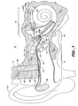
- FIG. 1 illustrates relative locations of components of a fully implantable hearing aid 10 after implantation in a temporal bone 11 of a human subject 12.
- FIG. 1 also depicts an external ear 13 located at one end of an external auditory canal 14, commonly identified as the ear canal.
- An opposite end of the external auditory canal 14 terminates at an ear drum 15.
- the ear drum 15 mechanically vibrates in response to sound waves that travel through the external auditory canal 14.
- the ear drum 15 serves as an anatomic barrier between the external auditory canal 14 and a middle ear cavity 16.
- the ear drum 15 amplifies sound waves by collecting them in a relatively large area and transmitting them to a much smaller area of an oval-shaped window 19.
- An inner ear 17 is located in the medial aspects of the temporal bone 11.
- the inner ear 17 is comprised of otic capsule bone containing the semi-circular canals for balance and a cochlea 20 for hearing.
- a relatively large bone, referred to as the promontory 18, projects from the otic capsule bone inferior to the oval window 19 which overlies a basal coil of the cochlea 20.
- a round window 29 is located on the opposite side of the promontory 18 from the oval window 19, and overlies a basal end of the scala tympani.
- ossicular chain 21 Three mobile bones (malleus, incus and stapes), referred to as an ossicular chain 21, span the middle ear cavity 16 to connect the ear drum 15 with the inner ear 17 at the oval window 19.
- the ossicular chain 21 conveys mechanical vibrations of the ear drum 15 to the inner ear 17, mechanically de-amplifying the motion by a factor of 2.2 at 1000 Hz.
- Vibrations of a stapes footplate 27 in the oval window 19 cause vibrations in perilymph fluid 20A contained in scala vestibuli of the cochlea 20.
- These pressure wave "vibrations" travel through the perilymph fluid 20A and endolymph fluid of the cochlea 20 to produce a traveling wave of the basilar membrane.
- Displacement of the basilar membrane bends "cilia" of the receptor cells 20B.
- the shearing effect of the cilia on the receptor cells 20B causes depolarization of the receptor cells 20B.
- Depolarization of the receptor cells 20B causes auditory signals to travel in a highly organized manner along auditory nerve fibers 20C, through the brainstem to eventually signal a temporal lobe of a brain of the subject 12 to perceive the vibrations as "sound.”
- the ossicular chain 21 is composed of a malleus 22, an incus 23, and a stapes 24.
- the stapes 24 is shaped like a "stirrup" with arches 25 and 26 and a stapes footplate 27 which covers the oval window 19.
- the mobile stapes 24 is supported in the oval window 19 by an annular ligament which attaches the stapes footplate 27 to the solid otic capsule margins of the oval window 19.
- FIG. 1 also illustrates the three major components of the hearing aid 10, a microphone 28, a signal-processing amplifier 30 which includes a battery not separately depicted in FIG. 1, and microactuator 32.
- Miniature cables or flexible printed circuits 33 and 34 respectively interconnect the signal-processing amplifier 30 with the microactuator 32, and with the microphone 28.
- the PCT Patent Application discloses that the microphone 28 consists of a very thin sheet of biocompatible, and implantable polyvinylidenefluoride (“PVDF”) that is identified commercially by a trademark KYNAR®.
- the microphone 28 disclosed in the PCT Patent Application has an area of approximately 0.5 to 2.0 square centimeter ("cm 2 ").
- the PCT Patent Application also discloses that the microphone 28 is preferably to be implanted below the skin in the auricle, or alternatively in the postauricular area of the external ear 13.
- the signal-processing amplifier 30 is implanted subcutaneously behind the external ear 13 within a depression 38 surgically sculpted in a mastoid cortical bone 39 of the subject 12.
- the signal-processing amplifier 30 receives a signal from the microphone 28 via the miniature cable 33, amplifies and conditions that signal, and then re-transmits the processed signal to the microactuator 32 via the miniature cable 34 implanted below the skin in the external auditory canal 14.
- the signal-processing amplifier 30 processes the signal received from the microphone 28 to optimally match characteristics of the processed signal to the microactuator 32 to obtain the desired auditory response.
- the signal-processing amplifier 30 may perform signal processing using either digital or analog signal processing, and may employ both nonlinear and highly complex signal processing.
- the microactuator 32 transduces the electrical signal received from the signal-processing amplifier 30 into vibrations that either directly or indirectly mechanically vibrate the perilymph fluid 20A in the inner ear 17. As described previously, vibrations in the perilymph fluid 20A actuate the receptor cells 20B to stimulate the auditory nerve fibers 20C which signal the brain of the subject 12 to perceive the mechanical vibrations as sound.
- FIG. 1 depicts the relative position of the microphone 28, the signal-processing amplifier 30 and the microactuator 32 with respect to the external ear 13.
- the subject 12 may control the operation of the hearing aid 10 using techniques analogous to those presently employed for controlling the operation of miniaturized external hearing aids.
- Both the microphone 28 and the microactuator 32 are so minuscule that their implantation requires little or no destruction of the tissue of the subject 12.
- the microphone 28 and the signal-processing amplifier 30 do not interfere with the normal conduction of sound through the ear, and thus will not impair hearing when the hearing aid 10 is turned off or not functioning.
- the PCT Patent Application provides a more detailed description of a signal-processing amplifier 30 and a microactuator 32 that are suitable for use in the present invention.
- FIG. 2a depicts an exploded, cross-sectional, elevational view of an implantable microphone 50 in accordance with the present invention.
- the implantable microphone 50 includes a diaphragm 52 preferably formed from a sheet of biocompatible metallic material such as titanium that is from 25 to 50 ⁇ m (one to two mils) thick.
- a central region 54 of the diaphragm 52 is lithographically etched to a thickness of approximately 5 to 12 microns.
- An outside rim 56, that surrounds the central region 54, is left thicker for ease of attachment to a housing 58 also included in the implantable microphone 50.
- the housing 58 is also preferably fabricated from a biocompatible material such as titanium.
- a sealing layer 62 may be applied to a surface of the diaphragm 52 nearest to the housing 58.
- the sealing layer 62 preferably consists of a thin layer of sputtered chromium, a few hundred angstroms thick, that is overcoated by a thicker layer of gold. This sealing layer 62, that is one to several microns thick, covers any potential cracks or pinholes in the thin central region 54 of the diaphragm 52.
- Etching of the diaphragm 52 may be patterned to produce a grid of intersecting reinforcing ribs 64, depicted in FIG. 2c, that protrude from a surface of the central region 54 furthest from the housing 58.
- the reinforcing ribs 64 subdivide the central region 54 into a plurality of separate membranes 66 that are mechanically supported by the reinforcing ribs 64.
- a sheet 72 of an electret material having a metalized surface such as a 12.5 ⁇ m (0.5 mil) thick Teflon film, is thermally bonded to the sealing layer 62 with the metalized side of the sheet 72 contacting the diaphragm 52.
- a surface of the sheet 72 furthest from the diaphragm 52 is then polarized by corona charging or electron bombardment.
- the assembly formed by the diaphragm 52 carrying the bonded electret sheet 72 is then pressed against an electrically conductive plate 82 disposed within the housing 58.
- An electrically insulating layer 84 is interposed between the plate 82 and the housing 58.
- the plate 82 either has a roughened surface 86 that is juxtaposed with the electret sheet 72; the surface 86 may be formed with a knurled or other controlled roughness.
- a contact 92 of an electrical connector 94 that pierces the housing 58 couples via the miniature cable 33 an input signal from the implantable microphone 50 to the signal-processing amplifier 30 included in the hearing aid 10.
- the thickness of plate 82 and of the layer 84 are chosen so the surface 86 of the plate 82 protrudes slightly above a rim 98 of the housing 58.
- the outside rim 56 of the diaphragm 52 is welded to the rim 98 of the housing 58. Because the surface 86 of the plate 82 protrudes above the rim 98 of the housing 58, welding the outside rim 56 to the rim 98 places the diaphragm 52 and the electret sheet 72 under tension, and presses the sheet 72 into contact with the plate 82 at many points, as illustrated in FIG. 2b.
- Acoustic waves impinging upon the central region 54 deflect the electret sheet 72 to thereby generate charges on the plate 82 that constitute an output signal from the implantable microphone 50.
- the housing 58 forms one electrode of the implantable microphone 50 while the contact 92 forms the other.
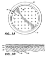
- FIGs. 3a and 3b depict an alternative embodiment for the plate 82.
- the embodiment of the plate 82 depicted in those FIGs. includes an array of lithographically defined posts 99 which establish a controlled roughness for the surface 86 of the plate 82 contacting the sheet 72.
- the posts 99 which are spaced 100 to 1000 microns apart, are formed by etching the surface 86 of the plate 82 to a depth between a few and 100 microns.
- the diameter of housing 58 may range from 5.0 mm to 25 mm, but for acoustical reasons preferably does not exceed 10.0 mm in diameter.
- the hermetically sealed implantable microphone 50 may be implanted subcutaneously, e.g. behind the external ear 13, with the central region 54 of the diaphragm 52 in intimate contact with skin 108 overlying the mastoid cortical bone 39 for minimal attenuation of sound.
- the implantable microphone 50 is rugged and can take direct blows.
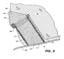
- the implantable microphone 50 described above may be combined with the signal-processing amplifier 30 to provide a disk-shaped, integrated electronics module 100 for the hearing aid 10, as illustrated in FIG. 4. Integrating both the signal-processing amplifier 30 and the implantable microphone 50 into the electronics module 100 as illustrated in FIG. 4 places the implantable microphone 50 on a side of the electronics module 100. Disposed in this location, the housing 58 and diaphragm 52 of the implantable microphone 50 now form part of a wall 102 of the electronics module 100, and the miniature cable 33 depicted in FIG. 1 passes directly between the implantable microphone 50 and the signal-processing amplifier 30 internally within the electronics module 100.
- the electronics module 100 essentially eliminates the miniature cable 33 connecting the implantable microphone 50 to the signal-processing amplifier 30 together with any possibility of its failure.
- the electronics module 100 carrying both the signal-processing amplifier 30 and the implantable microphone 50 may be implanted subcutaneously behind the external ear 13 of the subject 12 within the depression 38 surgically sculpted in the mastoid cortical bone 39.
- the depression 38, surgically sculpted to accept a biocompatible, metallic sleeve 132 that receives the electronics module 100, should not be more than 5 mm deep, and should be formed with rounded corners to avoid concentrating stress at sharp corners that would weaken the mastoid cortical bone 39.
- the sleeve 132 is permanently secured in the depression 38 to facilitate removing and/or replacing the electronics module 100. Disposing the electronics module 100 in this location leaves only the miniature cable 34 that couples an output signal from the signal-processing amplifier 30 to the microactuator 32.
- the diaphragm 52 and the housing 58 of the implantable microphone 50 as well as a disk-shaped housing 112 for the electronics module 100 is typically made of biocompatible metals such as titanium, titanium alloys or stainless steel.
- the disk-shaped housing 112 may have a diameter of 1.0 to 3.0 cm, and a height typically of 0.5 to 1.0 cm to accommodate the amplifier's electronics and the battery. Even if the housing 112 for the electronics module 100 were an elongated cylinder rather than disk-shaped, a cylindrically-curved wall 102 can still incorporate the implantable microphone 50. Under such circumstances, the central region 54 of the diaphragm 52 has the same curvature as that of the cylindrically-curved wall 102.
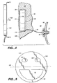
- FIG. 5 is a plan view depicting another embodiment of the electronics module 100 adapted for implantation as described above in connection with FIG. 4. It appears that a preferred location for implanting the electronics module 100 exist with the implantable microphone 50 located below a temporal line 122 on the subject 12. This location provides for relatively thin skin 108 over the implantable microphone 50 in the lower half of the electronics module 100, and for thicker skin 108 over the upper part of the electronics module 100.
- An on-off pressure switch 124 may be located on the housing 112 of the electronics module 100 above the temporal line 122 together with a pressure volume-control 126. Disposed in this location, the subject 12 may control operation of the hearing aid 10 by pressing on the skin 108 overlying the on-off pressure switch 124 and the pressure volume-control 126.
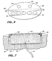
- FIG. 6 depicts an oval-shaped alternative embodiment of the electronics module 100 depicted in FIG. 5.
- the embodiment depicted in FIG. 6 includes a acoustic array 128 of individual implantable microphones 50 arranged in a horizontal row across the electronics module 100.
- a acoustic array 128 of individual implantable microphones 50 arranged in a horizontal row across the electronics module 100.
- an appropriately adapted signal-processing amplifier 30 sums independently generated signals from the implantable microphones 50, applying appropriate weighing factors to the signal from each implantable microphone 50, to produce a desired characteristic sensitivity pattern from the array 128. In this way the hearing aid 10 can provide the subject 12 with directivity which the subject 12 may use to enhance the sounds of interest while concurrently reducing noise.
- the wavelength of sound in air is only 6.8 cm.
- Providing a directional array that is one-half wavelength long at 5000 Hz requires that the array 128 be only a few centimeters long.
- output signals from each of the implantable microphones 50 of the array 128 are then coupled to the signal-processing amplifier 30.
- the signal-processing amplifier 30 appropriately weighs the output signals from each of the implantable microphones 50 with a pre-established distribution to produce a directional pattern for the sound perceived by the subject 12.
- Implanting the array 128 on the mastoid cortical bone 39 of the subject 12 near the external ear 13 provides such a directional sound receiving pattern.
- the subject 12 may use the radiation pattern to advantage in improving reception of such sounds, and to reject noise.
- the electronics module 100 is preferably received into the sleeve 132 that is permanently implanted (e.g. tapped) into the mastoid cortical bone 39 of the subject 12.
- An outer surface of the permanently implanted sleeve 132 may contain ridges 80-130 micron deep to encourage post-implantation growth of bone to lock the housing 112.
- the permanently implanted sleeve 132 includes a center post 134 that provides a permanent connection for the miniature cable 34 from the microactuator 32.
- the electronics module 100 is retained within the sleeve 132 by a locking ring 136, and O-rings 138 seal between the electronics module 100 and both the sleeve 132 and the locking ring 136.
- the O-rings 138 block entry of body fluids into any gap 142 between the electronics module 100 and the sleeve 132.
- the gap 142 may be filled with an electrically insulating, biocompatible gel material preferably having a cohesive strength that exceeds the material's adhesive strength with the outer surface of the electronics module 100, the sleeve 132 and the center post 134.
- the implantable microphone 50 may be preferably disposed at another location on the housing 112.
- the implantable microphone 50 is preferably located at one end of the cylindrically shaped housing 112.
- Such a cylindrically-shaped electronics module 100 is preferably implanted subcutaneously with the implantable microphone 50 located adjacent to the skin 108 of the external auditory canal 14 or adjacent to the conchal cartilage in the posterior external auditory canal 14. Disposed in such a location, the implantable microphone 50 presses downward against the skin 108 of the external auditory canal 14 as illustrated in FIG. 8, or against the conchal cartilage.
- the diaphragm 52 of the implantable microphone 50 may be domed outward to improve contact with the skin 108 or the conchal cartilage. Disposing the implantable microphone 50 in contact with skin 108 or the conchal cartilage of the external auditory canal 14 benefits from a substantial enhancement of sound waves at the implantable microphone 50 provided by the external ear 13.
- the housing 112 is made long enough so controls are available through the skin 108 at the end of the housing 112 distal from the implantable microphone 50.
- a biocompatible, metallic support sleeve 152 is preferably permanently anchored to the mastoid cortical bone 39 to receive the cylindrically-shaped electronics module 100, to facilitate its replacement, and to provide a fixed attachment for the electronics module 100.
- the housing 112 of the electronics module 100 is encircled by corrugated bellows 156 to accommodate anatomical differences by adjusting the length of the electronics module 100, and to facilitate installing the electronics module 100. Implanted in this way, the implantable microphone 50 is protected from direct blows.
- the electronics module 100 may be adapted for non-contact recharging of an energy storage device such as a battery, or equivalently a super capacitor, which powers operation of the hearing aid 10.
- an energy storage device such as a battery, or equivalently a super capacitor
- Such non-contact recharging can be effected by disposing an induction coil 160 adjacent to the skin 108 covering the electronics module 100 as indicated by an arrow 162 in FIG. 4.
Abstract
Description
- The present invention relates to fully implantable hearing aid system, and more particularly to an electret microphone adapted for use in such fully implantable hearing aid systems, and how such an electret microphone or other type of microphone may be incorporated into the fully implantable hearing aid system.
- Patent Cooperation Treaty ("PCT") patent application no. PCT/US96/15087 filed September 19, 1996, (postpublished as WO97/11575) entitled "Implantable Hearing Aid" ("the PCT Patent Application") describes a fully implantable hearing aid system which uses a very small implantable microactuator. The PCT Patent Application also discloses a Kynar® microphone which may be physically separated far enough from the implanted microactuator so that no feedback occurs. The fully implantable hearing aid system disclosed in the PCT Patent Application can operate for a period of five years on a set of batteries, and produce sound levels of 110 dB. The fully implantable hearing aid system described in the PCT Patent Applications is extremely compact, sturdy, rugged, and provides significant progress towards addressing problems with presently available hearing aids.
- While the Kynar microphone disclosed in the PCT Patent Application enables an operable fully implantable hearing aid system, that system's performance may be improved through the use of a more sensitive electret microphone. United States patents nos. 4,957,478 ("the '478 patent") and 5,015,224, a division of the '478 patent, disclose incorporating a conventional electret microphone into an outer
ear canal unit 34 of a partially implantable hearing aid system. United States patent no. 5,408,534 entitled "Electret Microphone Assembly, and Method of Manufacture" discloses an improved structure and method for coupling a charge plate of the electret microphone used in a hearing aid to an input terminal of an impedance matching circuit or internal amplifier. One difficulty with using an electret microphone for a fully implantable hearing aid system not addressed by the patents identified above is that the microphone must be hermetically sealed to prevent electret de-polarization while simultaneously permitting sound waves to impinge upon the microphone. - US-A-5,411,467 discloses an implantable hearing aid having an electromechanical converter which generates mechanical vibrations that a hydromechanical coupling element transmits to the fluid of the inner ear. In one configuration, the hydromechanical coupling element is a fluid-filled tube connected to the electromechanical converter and having a distal end that extends into the fluid-filled inner ear. The electromechanical converter can be integrated within a housing of an implantable signal processing electronic device and can operate on the basis of electrodynamic, electromagnetic or, preferably, piezoelectric principles. A microphone included in the implantable hearing aid supplies input signals to the electromechanical converter via a signal processing electronic device. The microphone is connected to an acoustic coupling element for picking up sound from the tympanic cavity, fully exploiting the natural directional capabilities of the outer ear.
- FR-A-2 659 009 discloses a hearing aid powered by an electrical supply that includes a vibration generator which is directly coupled to the mastoid bone. This direct bone conduction hearing aid includes a means for receiving and converting sounds into analog signals, then processing these signals according to the needs of the hearing-impaired person before transmitting the signals to the vibration generator. The hearing aid is self-contained, can be implanted and positioned beneath the skin, and includes rechargeable batteries together with an induction coil for receiving an alternating magnetic field which, from time to time, is disposed near the hearing aid.
- Because the hearing aid system disclosed in the above-identified PCT Patent Application is fully implanted, it is presently estimated that after a five year interval of use the system's battery may likely need replacement which necessarily involves surgery. Another aspect of a fully implantable hearing aid system is ensuring reliable electrical interconnection of the system's microphone and microactuator to the system's signal-processing amplifier throughout a five year interval prior to battery replacement, and subsequently after the battery has been replaced.
- The present invention is defined in claim 1 below, and aims to provide an electret microphone adapted for incorporation into a fully implantable hearing aid system, which is relatively simple and which incorporates the microphone into an implanted housing that contains the hearing aid's amplifier and battery. Another aim is to provide an improved structure for implanting a housing enclosing a fully implantable hearing aid's amplifier and battery into a depression surgically sculpted in a subject's mastoid cortical bone, and another is to provide a structure for a fully implantable hearing aid's housing that encloses an amplifier and battery which provides ready tactile access to hearing aid operating controls.
- Briefly, the present invention includes a sealed microphone adapted for inclusion in an implantable hearing aid system. The sealed implantable microphone provides an input signal to an amplifier included in the implantable hearing aid system. The microphone includes a diaphragm having a thin central region surrounded by a thicker rim. An electret, which is bonded to the diaphragm, contacts a roughened plate included in the microphone. The rim of the diaphragm is bonded to a surface of a housing to hermetically enclose the electret and the plate, the plate being electrically insulated from the housing. The microphone also includes an electrical connector coupled both to the plate and through the housing to the electret for providing the input signal to the amplifier of the implantable hearing aid system.
- This implantable microphone is preferably incorporated into a hermetically sealed electronics module. In addition to the microphone, the electronics module includes an amplifier that receives the input signal from the microphone's plate and the electret, and provides an output signal to a microactuator also included in the implantable hearing aid system. The electronics module also includes a battery for energizing operation of the implantable hearing aid system. A housing for the electronics module receives the battery, the amplifier, the plate, and the electret. The microphone's diaphragm forms a surface of the housing with the rim of the diaphragm being bonded to the housing thereby hermetically sealing the electronics module. An electrical connector coupled to the amplifier provides the output signal to the microactuator of the implantable hearing aid system.
- These and other features, objects and advantages will be understood or apparent to those of ordinary skill in the art from the following detailed description of the preferred embodiment as illustrated in the various drawing figures.
-
- FIG. 1 is a schematic coronal, partial sectional view through a human temporal bone illustrating the external, middle and inner ears, and showing the relative positions of the components of a fully implantable hearing aid system disclosed in the PCT Patent Application;
- FIG. 2a is an exploded, cross-sectional elevational view illustrating an electret microphone in accordance with the present invention including a diaphragm, an electret, a plate that contacts a surface of the electret, and a hermetically sealed housing that encloses the electret and plate;
- FIG. 2b is an enlarged cross-sectional elevational view taken along the line 2b-2b of FIG. 2a illustrating contact between the electret and the plate;
- FIG. 2c is a plan view taken along the line 2c-2c of FIG. 2a illustrating the diaphragm and reinforcing ribs that subdivide a thinned central region of the diaphragm;
- FIG. 3a is a plan view of an alternative embodiment structure for the plate depicted in the cross-sectional view of FIG. 2a;
- FIG. 3b is a cross-sectional view, similar to the view of FIG. 2b, of the alternative embodiment structure for the plate depicted in the plan view of FIG. 3a;
- FIG. 4 is a cross-sectional elevational view illustrating implantation into a cavity sculpted into a mastoid bone located behind the ear of an electronics module that includes an electret microphone, an amplifier and battery for energizing operation of the fully implantable hearing aid system;
- FIG. 5 is an elevational view of a disk-shaped implantable electronics module taken along a line 4-4 in FIG 3 that illustrates a preferred arrangement for the electronics module, and indicates a preferred vertical location for its implantation on the mastoid bone;
- FIG. 6 is an elevational view of an alternative embodiment of an oval-shaped implantable electronics module, similar to the disk-shaped electronics module depicted in FIG. 5, that includes a plurality of microphones;
- FIG. 7 is a partial cross-sectional view depicting a permanently implanted sleeve adapted to receive and facilitate replacement of the electronics module such as those depicted in FIGs. 4, 5 and 6;
- FIG. 8 is a schematic coronal, partial sectional view through a human temporal bone, similar to the partial sectional view of FIG. 1, illustrating implantation into a cavity sculpted there of an electronics module that includes an amplifier, a battery, and a microphone which presses against the skin of the external auditory canal; and
- FIG. 9 is an enlarged cross-sectional view of a sleeve preferably used for supporting the electronics module when implanted as depicted in FIG. 8.
-
- FIG. 1 illustrates relative locations of components of a fully
implantable hearing aid 10 after implantation in atemporal bone 11 of ahuman subject 12. FIG. 1 also depicts anexternal ear 13 located at one end of anexternal auditory canal 14, commonly identified as the ear canal. An opposite end of the externalauditory canal 14 terminates at anear drum 15. Theear drum 15 mechanically vibrates in response to sound waves that travel through the externalauditory canal 14. Theear drum 15 serves as an anatomic barrier between the externalauditory canal 14 and amiddle ear cavity 16. Theear drum 15 amplifies sound waves by collecting them in a relatively large area and transmitting them to a much smaller area of an oval-shapedwindow 19. Aninner ear 17 is located in the medial aspects of thetemporal bone 11. Theinner ear 17 is comprised of otic capsule bone containing the semi-circular canals for balance and acochlea 20 for hearing. A relatively large bone, referred to as thepromontory 18, projects from the otic capsule bone inferior to theoval window 19 which overlies a basal coil of thecochlea 20. Around window 29 is located on the opposite side of thepromontory 18 from theoval window 19, and overlies a basal end of the scala tympani. - Three mobile bones (malleus, incus and stapes), referred to as an
ossicular chain 21, span themiddle ear cavity 16 to connect theear drum 15 with theinner ear 17 at theoval window 19. Theossicular chain 21 conveys mechanical vibrations of theear drum 15 to theinner ear 17, mechanically de-amplifying the motion by a factor of 2.2 at 1000 Hz. Vibrations of astapes footplate 27 in theoval window 19 cause vibrations inperilymph fluid 20A contained in scala vestibuli of thecochlea 20. These pressure wave "vibrations" travel through theperilymph fluid 20A and endolymph fluid of the cochlea 20 to produce a traveling wave of the basilar membrane. Displacement of the basilar membrane bends "cilia" of thereceptor cells 20B. The shearing effect of the cilia on thereceptor cells 20B causes depolarization of thereceptor cells 20B. Depolarization of thereceptor cells 20B causes auditory signals to travel in a highly organized manner alongauditory nerve fibers 20C, through the brainstem to eventually signal a temporal lobe of a brain of the subject 12 to perceive the vibrations as "sound." - The
ossicular chain 21 is composed of amalleus 22, anincus 23, and a stapes 24. The stapes 24 is shaped like a "stirrup" witharches stapes footplate 27 which covers theoval window 19. Themobile stapes 24 is supported in theoval window 19 by an annular ligament which attaches the stapes footplate 27 to the solid otic capsule margins of theoval window 19. - FIG. 1 also illustrates the three major components of the
hearing aid 10, amicrophone 28, a signal-processingamplifier 30 which includes a battery not separately depicted in FIG. 1, andmicroactuator 32. Miniature cables or flexible printedcircuits amplifier 30 with themicroactuator 32, and with themicrophone 28. The PCT Patent Application discloses that themicrophone 28 consists of a very thin sheet of biocompatible, and implantable polyvinylidenefluoride ("PVDF") that is identified commercially by a trademark KYNAR®. Themicrophone 28 disclosed in the PCT Patent Application has an area of approximately 0.5 to 2.0 square centimeter ("cm2"). The PCT Patent Application also discloses that themicrophone 28 is preferably to be implanted below the skin in the auricle, or alternatively in the postauricular area of theexternal ear 13. - The signal-processing
amplifier 30 is implanted subcutaneously behind theexternal ear 13 within adepression 38 surgically sculpted in a mastoidcortical bone 39 of the subject 12. The signal-processingamplifier 30 receives a signal from themicrophone 28 via theminiature cable 33, amplifies and conditions that signal, and then re-transmits the processed signal to themicroactuator 32 via theminiature cable 34 implanted below the skin in the externalauditory canal 14. The signal-processingamplifier 30 processes the signal received from themicrophone 28 to optimally match characteristics of the processed signal to themicroactuator 32 to obtain the desired auditory response. The signal-processingamplifier 30 may perform signal processing using either digital or analog signal processing, and may employ both nonlinear and highly complex signal processing. - The
microactuator 32 transduces the electrical signal received from the signal-processingamplifier 30 into vibrations that either directly or indirectly mechanically vibrate theperilymph fluid 20A in theinner ear 17. As described previously, vibrations in theperilymph fluid 20A actuate thereceptor cells 20B to stimulate theauditory nerve fibers 20C which signal the brain of the subject 12 to perceive the mechanical vibrations as sound. - FIG. 1 depicts the relative position of the
microphone 28, the signal-processingamplifier 30 and themicroactuator 32 with respect to theexternal ear 13. Even though the signal-processingamplifier 30 is implanted subcutaneously, the subject 12 may control the operation of thehearing aid 10 using techniques analogous to those presently employed for controlling the operation of miniaturized external hearing aids. Both themicrophone 28 and themicroactuator 32 are so minuscule that their implantation requires little or no destruction of the tissue of the subject 12. Of equal importance, themicrophone 28 and the signal-processingamplifier 30 do not interfere with the normal conduction of sound through the ear, and thus will not impair hearing when thehearing aid 10 is turned off or not functioning. - The PCT Patent Application provides a more detailed description of a signal-processing
amplifier 30 and amicroactuator 32 that are suitable for use in the present invention. - FIG. 2a depicts an exploded, cross-sectional, elevational view of an
implantable microphone 50 in accordance with the present invention. Theimplantable microphone 50 includes adiaphragm 52 preferably formed from a sheet of biocompatible metallic material such as titanium that is from 25 to 50 µm (one to two mils) thick. Acentral region 54 of thediaphragm 52 is lithographically etched to a thickness of approximately 5 to 12 microns. Anoutside rim 56, that surrounds thecentral region 54, is left thicker for ease of attachment to ahousing 58 also included in theimplantable microphone 50. Thehousing 58 is also preferably fabricated from a biocompatible material such as titanium. Asealing layer 62 may be applied to a surface of thediaphragm 52 nearest to thehousing 58. Thesealing layer 62 preferably consists of a thin layer of sputtered chromium, a few hundred angstroms thick, that is overcoated by a thicker layer of gold. Thissealing layer 62, that is one to several microns thick, covers any potential cracks or pinholes in the thincentral region 54 of thediaphragm 52. - Etching of the
diaphragm 52 may be patterned to produce a grid ofintersecting reinforcing ribs 64, depicted in FIG. 2c, that protrude from a surface of thecentral region 54 furthest from thehousing 58. The reinforcingribs 64 subdivide thecentral region 54 into a plurality ofseparate membranes 66 that are mechanically supported by the reinforcingribs 64. - After fabricating the
diaphragm 52 with itssealing layer 62, asheet 72 of an electret material having a metalized surface, such as a 12.5 µm (0.5 mil) thick Teflon film, is thermally bonded to thesealing layer 62 with the metalized side of thesheet 72 contacting thediaphragm 52. A surface of thesheet 72 furthest from thediaphragm 52 is then polarized by corona charging or electron bombardment. - The assembly formed by the
diaphragm 52 carrying the bondedelectret sheet 72 is then pressed against an electricallyconductive plate 82 disposed within thehousing 58. An electrically insulatinglayer 84 is interposed between theplate 82 and thehousing 58. As depicted in FIG. 2b, theplate 82 either has a roughenedsurface 86 that is juxtaposed with theelectret sheet 72; thesurface 86 may be formed with a knurled or other controlled roughness. Acontact 92 of anelectrical connector 94 that pierces thehousing 58 couples via theminiature cable 33 an input signal from theimplantable microphone 50 to the signal-processingamplifier 30 included in thehearing aid 10. - The thickness of
plate 82 and of thelayer 84 are chosen so thesurface 86 of theplate 82 protrudes slightly above arim 98 of thehousing 58. Theoutside rim 56 of thediaphragm 52 is welded to therim 98 of thehousing 58. Because thesurface 86 of theplate 82 protrudes above therim 98 of thehousing 58, welding theoutside rim 56 to therim 98 places thediaphragm 52 and theelectret sheet 72 under tension, and presses thesheet 72 into contact with theplate 82 at many points, as illustrated in FIG. 2b. Acoustic waves impinging upon thecentral region 54 deflect theelectret sheet 72 to thereby generate charges on theplate 82 that constitute an output signal from theimplantable microphone 50. Thehousing 58 forms one electrode of theimplantable microphone 50 while thecontact 92 forms the other. - FIGs. 3a and 3b depict an alternative embodiment for the
plate 82. The embodiment of theplate 82 depicted in those FIGs. includes an array of lithographically definedposts 99 which establish a controlled roughness for thesurface 86 of theplate 82 contacting thesheet 72. Theposts 99, which are spaced 100 to 1000 microns apart, are formed by etching thesurface 86 of theplate 82 to a depth between a few and 100 microns. - The diameter of
housing 58 may range from 5.0 mm to 25 mm, but for acoustical reasons preferably does not exceed 10.0 mm in diameter. The hermetically sealedimplantable microphone 50 may be implanted subcutaneously, e.g. behind theexternal ear 13, with thecentral region 54 of thediaphragm 52 in intimate contact withskin 108 overlying the mastoidcortical bone 39 for minimal attenuation of sound. Theimplantable microphone 50 is rugged and can take direct blows. - The
implantable microphone 50 described above may be combined with the signal-processingamplifier 30 to provide a disk-shaped,integrated electronics module 100 for thehearing aid 10, as illustrated in FIG. 4. Integrating both the signal-processingamplifier 30 and theimplantable microphone 50 into theelectronics module 100 as illustrated in FIG. 4 places theimplantable microphone 50 on a side of theelectronics module 100. Disposed in this location, thehousing 58 anddiaphragm 52 of theimplantable microphone 50 now form part of awall 102 of theelectronics module 100, and theminiature cable 33 depicted in FIG. 1 passes directly between theimplantable microphone 50 and the signal-processingamplifier 30 internally within theelectronics module 100. Theelectronics module 100 essentially eliminates theminiature cable 33 connecting theimplantable microphone 50 to the signal-processingamplifier 30 together with any possibility of its failure. - For a
hearing aid 10 having anintegrated electronics module 100, as described in the PCT Patent Application theelectronics module 100 carrying both the signal-processingamplifier 30 and theimplantable microphone 50 may be implanted subcutaneously behind theexternal ear 13 of the subject 12 within thedepression 38 surgically sculpted in the mastoidcortical bone 39. Thedepression 38, surgically sculpted to accept a biocompatible,metallic sleeve 132 that receives theelectronics module 100, should not be more than 5 mm deep, and should be formed with rounded corners to avoid concentrating stress at sharp corners that would weaken the mastoidcortical bone 39. Thesleeve 132 is permanently secured in thedepression 38 to facilitate removing and/or replacing theelectronics module 100. Disposing theelectronics module 100 in this location leaves only theminiature cable 34 that couples an output signal from the signal-processingamplifier 30 to themicroactuator 32. - The
diaphragm 52 and thehousing 58 of theimplantable microphone 50 as well as a disk-shapedhousing 112 for theelectronics module 100 is typically made of biocompatible metals such as titanium, titanium alloys or stainless steel. The disk-shapedhousing 112 may have a diameter of 1.0 to 3.0 cm, and a height typically of 0.5 to 1.0 cm to accommodate the amplifier's electronics and the battery. Even if thehousing 112 for theelectronics module 100 were an elongated cylinder rather than disk-shaped, a cylindrically-curved wall 102 can still incorporate theimplantable microphone 50. Under such circumstances, thecentral region 54 of thediaphragm 52 has the same curvature as that of the cylindrically-curved wall 102. - FIG. 5 is a plan view depicting another embodiment of the
electronics module 100 adapted for implantation as described above in connection with FIG. 4. It appears that a preferred location for implanting theelectronics module 100 exist with theimplantable microphone 50 located below atemporal line 122 on the subject 12. This location provides for relativelythin skin 108 over theimplantable microphone 50 in the lower half of theelectronics module 100, and forthicker skin 108 over the upper part of theelectronics module 100. An on-offpressure switch 124 may be located on thehousing 112 of theelectronics module 100 above thetemporal line 122 together with a pressure volume-control 126. Disposed in this location, the subject 12 may control operation of thehearing aid 10 by pressing on theskin 108 overlying the on-offpressure switch 124 and the pressure volume-control 126. - FIG. 6 depicts an oval-shaped alternative embodiment of the
electronics module 100 depicted in FIG. 5. The embodiment depicted in FIG. 6 includes aacoustic array 128 of individualimplantable microphones 50 arranged in a horizontal row across theelectronics module 100. As described in greater detail in United States Patent Application Serial no. 08/801,056 entitled "Improved Biocompatible Transducers" filed February 14, 1997, and in Patent Cooperation Treaty ("PCT") International Patent Application PCT/US97/02323 (postpublished as WO97/30565) having the same title and filing date ("the Improved Biocompatible Transducers patent applications"), an appropriately adapted signal-processingamplifier 30 sums independently generated signals from theimplantable microphones 50, applying appropriate weighing factors to the signal from eachimplantable microphone 50, to produce a desired characteristic sensitivity pattern from thearray 128. In this way thehearing aid 10 can provide the subject 12 with directivity which the subject 12 may use to enhance the sounds of interest while concurrently reducing noise. - At 5000 Hz, the wavelength of sound in air is only 6.8 cm. Providing a directional array that is one-half wavelength long at 5000 Hz requires that the
array 128 be only a few centimeters long. output signals from each of theimplantable microphones 50 of thearray 128 are then coupled to the signal-processingamplifier 30. The signal-processingamplifier 30 appropriately weighs the output signals from each of theimplantable microphones 50 with a pre-established distribution to produce a directional pattern for the sound perceived by the subject 12. Implanting thearray 128 on the mastoidcortical bone 39 of the subject 12 near theexternal ear 13 provides such a directional sound receiving pattern. By directing the maximum sensitivity of thearray 128 toward sounds of interest, it is readily apparent that the subject 12 may use the radiation pattern to advantage in improving reception of such sounds, and to reject noise. - With the configurations for the
electronics module 100 depicted in FIGs. 4, 5 and 6, theelectronics module 100 is preferably received into thesleeve 132 that is permanently implanted (e.g. tapped) into the mastoidcortical bone 39 of the subject 12. An outer surface of the permanently implantedsleeve 132 may contain ridges 80-130 micron deep to encourage post-implantation growth of bone to lock thehousing 112. The permanently implantedsleeve 132 includes acenter post 134 that provides a permanent connection for theminiature cable 34 from themicroactuator 32. Theelectronics module 100 is retained within thesleeve 132 by alocking ring 136, and O-rings 138 seal between theelectronics module 100 and both thesleeve 132 and thelocking ring 136. The O-rings 138 block entry of body fluids into anygap 142 between theelectronics module 100 and thesleeve 132. Moreover, thegap 142 may be filled with an electrically insulating, biocompatible gel material preferably having a cohesive strength that exceeds the material's adhesive strength with the outer surface of theelectronics module 100, thesleeve 132 and thecenter post 134. - If the
electronics module 100 is cylindrically-shaped rather disk-shaped, then theimplantable microphone 50 may be preferably disposed at another location on thehousing 112. For such a configuration of theelectronics module 100, as illustrated in FIG. 8 theimplantable microphone 50 is preferably located at one end of the cylindrically shapedhousing 112. Such a cylindrically-shapedelectronics module 100 is preferably implanted subcutaneously with theimplantable microphone 50 located adjacent to theskin 108 of the externalauditory canal 14 or adjacent to the conchal cartilage in the posterior externalauditory canal 14. Disposed in such a location, theimplantable microphone 50 presses downward against theskin 108 of the externalauditory canal 14 as illustrated in FIG. 8, or against the conchal cartilage. Thediaphragm 52 of theimplantable microphone 50 may be domed outward to improve contact with theskin 108 or the conchal cartilage. Disposing theimplantable microphone 50 in contact withskin 108 or the conchal cartilage of the externalauditory canal 14 benefits from a substantial enhancement of sound waves at theimplantable microphone 50 provided by theexternal ear 13. Thehousing 112 is made long enough so controls are available through theskin 108 at the end of thehousing 112 distal from theimplantable microphone 50. As illustrated in FIG. 9, a biocompatible,metallic support sleeve 152 is preferably permanently anchored to the mastoidcortical bone 39 to receive the cylindrically-shapedelectronics module 100, to facilitate its replacement, and to provide a fixed attachment for theelectronics module 100. Thehousing 112 of theelectronics module 100 is encircled bycorrugated bellows 156 to accommodate anatomical differences by adjusting the length of theelectronics module 100, and to facilitate installing theelectronics module 100. Implanted in this way, theimplantable microphone 50 is protected from direct blows. - Referring back to FIG. 4, with the
electronics module 100 implanted subcutaneously behind theexternal ear 13 of the subject 12 theelectronics module 100 may be adapted for non-contact recharging of an energy storage device such as a battery, or equivalently a super capacitor, which powers operation of thehearing aid 10. Such non-contact recharging can be effected by disposing aninduction coil 160 adjacent to theskin 108 covering theelectronics module 100 as indicated by anarrow 162 in FIG. 4. - Although the present invention has been described in terms of the presently preferred embodiment, it is to be understood that such disclosure is purely illustrative and is not to be interpreted as limiting. Consequently, without departing from the scope of the invention, various alterations, modifications, and/or alternative applications of the invention will, no doubt, be suggested to those skilled in the art after having read the preceding disclosure.
Claims (15)
- A sealed microphone (50) adapted for inclusion in an implantable hearing aid system to provide an input signal to an amplifier (30) included in the implantable hearing aid system, the microphone being characterized by:a diaphragm (52) having a thin central region (54) surrounded by a thicker rim (56);an electret (72) bonded to said diaphragm (52);a roughened plate (82) contacted by said electret (72);a housing (58) for receiving said plate and said electret, said housing being electrically insulated from said plate, the rim of said diaphragm being bonded to a surface of said housing thereby hermetically sealing the microphone; andan electrical connector (94) coupled both to said plate (82) and said electret for providing the input signal to the amplifier of the implantable hearing aid system.
- The microphone of claim 1, wherein said diaphragm is formed by a metallic sheet that is lithographically etched to form the thin central region thereof.
- The microphone of claim 2, wherein the metallic sheet is formed from titanium.
- The microphone of claim 2, wherein the metallic sheet is coated with a sealing layer of material.
- The microphone of claim 4, wherein the sealing layer is formed from gold.
- The microphone of any one of the preceding claims, wherein the thin central region of said diaphragm includes a plurality of reinforcing ribs (64) that subdivide the central region into a plurality of individual membranes (66).
- The microphone of any one of the preceding claims, wherein the electret includes an electrically conductive layer that contacts said diaphragm.
- The microphone of claim 7, wherein the electrically conductive layer is formed by a layer of metallic material.
- The microphone of any one of the preceding claims further comprising electrical leads for coupling the microphone to the amplifier.
- The microphone of any one of the preceding claims, wherein said plate is roughened by a plurality of posts (99) formed thereon.
- A sealed, implantable electronics module (100) adapted for inclusion in an implantable hearing aid system, the electronics module (100) comprising:a microphone (50) which includes:a diaphragm (52) having a thin central region (54) surrounded by a thicker rim (56);an electret (72) bonded to said diaphragm;a roughened plate (82) contacted by said electret (72) ;an amplifier (30) for receiving an input signal from said microphone, and for providing an output signal to a microactuator (32) also included in the implantable hearing aid system;an energy storage device for powering operation of the implantable hearing aid system;a housing (58) for receiving and hermetically enclosing said microphone (50), said amplifier (30) and said energy storage device, said housing receiving said plate and said electret of said microphone and being electrically insulated from said plate, the rim of said diaphragm being bonded to a surface of said housing thereby hermetically sealing the microphone, and said plate and said electret; andan electrical connector (94) coupled to said amplifier for providing the output signal to the microactuator of the implantable hearing aid system.
- The electronics module of claim 11, wherein said electronics module is adapted to be mechanically received by and electrically coupled to a sleeve (132) that is included in the implantable hearing aid system, the electrical coupling of the electronics module to the sleeve providing the output signal from said amplifier to the microactuator, said sleeve being adapted for permanent implantation into a subject to thereby facilitate replacement of said electronics module.
- The electronics module of claim 11 or 12, wherein said electronics module is disk-shaped and adapted for implantation into a depression surgically sculpted into a mastoid cortical bone behind an external ear of a subject, disposed in this location said microphone is adapted to press against skin overlying said mastoid cortical bone.
- The electronics module of claim 11, 12 or 13, wherein said electronics module is cylindrically-shaped and adapted for implantation into a depression surgically sculpted into a mastoid cortical bone of a subject, disposed in this location said microphone is adapted to press against skin or conchal cartilage of an external auditory canal.
- The electronics module of claim 11, 12 or 13, wherein said electronics module is further adapted to permit non-contact recharging of said energy storage device that energizes operation of the implantable hearing aid system.
Priority Applications (1)
| Application Number | Priority Date | Filing Date | Title |
|---|---|---|---|
| EP05016178A EP1596629A3 (en) | 1996-05-24 | 1997-05-23 | Electronic module for implantable hearing aid |
Applications Claiming Priority (3)
| Application Number | Priority Date | Filing Date | Title |
|---|---|---|---|
| US1829996P | 1996-05-24 | 1996-05-24 | |
| US18299P | 1996-05-24 | ||
| PCT/US1997/008748 WO1997044987A1 (en) | 1996-05-24 | 1997-05-23 | Improved microphones for an implantable hearing aid |
Publications (3)
| Publication Number | Publication Date |
|---|---|
| EP0963683A1 EP0963683A1 (en) | 1999-12-15 |
| EP0963683A4 EP0963683A4 (en) | 2004-03-31 |
| EP0963683B1 true EP0963683B1 (en) | 2005-07-27 |
Family
ID=21787237
Family Applications (1)
| Application Number | Title | Priority Date | Filing Date |
|---|---|---|---|
| EP97924795A Expired - Lifetime EP0963683B1 (en) | 1996-05-24 | 1997-05-23 | Improved microphones for an implantable hearing aid |
Country Status (8)
| Country | Link |
|---|---|
| US (2) | US5881158A (en) |
| EP (1) | EP0963683B1 (en) |
| JP (1) | JP3801212B2 (en) |
| KR (1) | KR20000016084A (en) |
| AU (1) | AU3010897A (en) |
| CA (1) | CA2256389C (en) |
| DE (1) | DE69733837T2 (en) |
| WO (1) | WO1997044987A1 (en) |
Families Citing this family (86)
| Publication number | Priority date | Publication date | Assignee | Title |
|---|---|---|---|---|
| US6532294B1 (en) * | 1996-04-01 | 2003-03-11 | Elliot A. Rudell | Automatic-on hearing aids |
| EP0981823A1 (en) * | 1996-04-18 | 2000-03-01 | California Institute Of Technology | Thin film electret microphone |
| DE19758573C2 (en) * | 1997-11-26 | 2001-03-01 | Implex Hear Tech Ag | Fixation element for an implantable microphone |
| US6093144A (en) * | 1997-12-16 | 2000-07-25 | Symphonix Devices, Inc. | Implantable microphone having improved sensitivity and frequency response |
| EP1308068A4 (en) * | 1998-06-05 | 2007-05-02 | St Croix Medical Inc | Method and apparatus for reduced feedback in implantable hearing assistance systems |
| DE19829637C2 (en) | 1998-07-02 | 2000-10-19 | Implex Hear Tech Ag | Medical implant |
| US6308101B1 (en) | 1998-07-31 | 2001-10-23 | Advanced Bionics Corporation | Fully implantable cochlear implant system |
| US6272382B1 (en) | 1998-07-31 | 2001-08-07 | Advanced Bionics Corporation | Fully implantable cochlear implant system |
| US6473651B1 (en) | 1999-03-02 | 2002-10-29 | Advanced Bionics Corporation | Fluid filled microphone balloon to be implanted in the middle ear |
| JP4819268B2 (en) * | 1999-08-26 | 2011-11-24 | メド−エル・エレクトロメディツィニシェ・ゲラーテ・ゲーエムベーハー | Electrical neural stimulation based on channel-specific sampling sequences |
| WO2001043489A2 (en) * | 1999-12-09 | 2001-06-14 | Sonionmicrotronic Nederland B.V. | Miniature microphone |
| US6516228B1 (en) * | 2000-02-07 | 2003-02-04 | Epic Biosonics Inc. | Implantable microphone for use with a hearing aid or cochlear prosthesis |
| US6865279B2 (en) | 2000-03-13 | 2005-03-08 | Sarnoff Corporation | Hearing aid with a flexible shell |
| DE10018361C2 (en) * | 2000-04-13 | 2002-10-10 | Cochlear Ltd | At least partially implantable cochlear implant system for the rehabilitation of a hearing disorder |
| US6517476B1 (en) | 2000-05-30 | 2003-02-11 | Otologics Llc | Connector for implantable hearing aid |
| CA2411782A1 (en) | 2000-06-30 | 2002-01-17 | Cochlear Limited | Cochlear implant |
| DE10041728A1 (en) * | 2000-08-25 | 2002-03-21 | Implex Hear Tech Ag | Implantable medicinal device with hermetically sealed housing has storage device accommodated directly within hermetically sealed housing without housing of its own |
| DE10046938A1 (en) * | 2000-09-21 | 2002-04-25 | Implex Ag Hearing Technology I | At least partially implantable hearing system with direct mechanical stimulation of a lymphatic space in the inner ear |
| KR200218653Y1 (en) * | 2000-11-01 | 2001-04-02 | 주식회사비에스이 | An electret condenser microphone |
| US6707920B2 (en) | 2000-12-12 | 2004-03-16 | Otologics Llc | Implantable hearing aid microphone |
| DE10062236C2 (en) * | 2000-12-14 | 2003-11-27 | Phonak Ag Staefa | Fixation element for an implantable microphone |
| US7181032B2 (en) * | 2001-03-13 | 2007-02-20 | Phonak Ag | Method for establishing a detachable mechanical and/or electrical connection |
| US6937735B2 (en) * | 2001-04-18 | 2005-08-30 | SonionMicrotronic Néderland B.V. | Microphone for a listening device having a reduced humidity coefficient |
| US7062058B2 (en) | 2001-04-18 | 2006-06-13 | Sonion Nederland B.V. | Cylindrical microphone having an electret assembly in the end cover |
| US7136496B2 (en) * | 2001-04-18 | 2006-11-14 | Sonion Nederland B.V. | Electret assembly for a microphone having a backplate with improved charge stability |
| US6829364B2 (en) | 2001-06-22 | 2004-12-07 | Topholm & Westermann Aps, Ny | Hearing aid with a capacitor having a large capacitance |
| US7065224B2 (en) * | 2001-09-28 | 2006-06-20 | Sonionmicrotronic Nederland B.V. | Microphone for a hearing aid or listening device with improved internal damping and foreign material protection |
| US6537201B1 (en) | 2001-09-28 | 2003-03-25 | Otologics Llc | Implantable hearing aid with improved sealing |
| US7239714B2 (en) * | 2001-10-09 | 2007-07-03 | Sonion Nederland B.V. | Microphone having a flexible printed circuit board for mounting components |
| WO2003037212A2 (en) * | 2001-10-30 | 2003-05-08 | Lesinski George S | Implantation method for a hearing aid microactuator implanted into the cochlea |
| US20030117442A1 (en) * | 2001-12-26 | 2003-06-26 | Yuemean Chen | Dynamic indication for capacitor charging status |
| US6714654B2 (en) | 2002-02-06 | 2004-03-30 | George Jay Lichtblau | Hearing aid operative to cancel sounds propagating through the hearing aid case |
| AU2002950754A0 (en) | 2002-08-09 | 2002-09-12 | Cochlear Limited | Mechanical design for a cochlear implant |
| US7974700B1 (en) * | 2002-08-09 | 2011-07-05 | Cochlear Limited | Cochlear implant component having a unitary faceplate |
| AU2002950755A0 (en) * | 2002-08-09 | 2002-09-12 | Cochlear Limited | Fixation system for a cochlear implant |
| WO2004030572A2 (en) * | 2002-10-02 | 2004-04-15 | Otologics Llc | Retention apparatus for an external portion of a semi-implantable hearing aid |
| US8280082B2 (en) * | 2002-10-08 | 2012-10-02 | Sonion Nederland B.V. | Electret assembly for a microphone having a backplate with improved charge stability |
| EP1435757A1 (en) * | 2002-12-30 | 2004-07-07 | Andrzej Zarowski | Device implantable in a bony wall of the inner ear |
| AU2003901867A0 (en) | 2003-04-17 | 2003-05-08 | Cochlear Limited | Osseointegration fixation system for an implant |
| US7524278B2 (en) * | 2003-05-19 | 2009-04-28 | Envoy Medical Corporation | Hearing aid system and transducer with hermetically sealed housing |
| AU2003904086A0 (en) | 2003-08-04 | 2003-08-21 | Cochlear Limited | Implant battery short circuit protection |
| US7556597B2 (en) * | 2003-11-07 | 2009-07-07 | Otologics, Llc | Active vibration attenuation for implantable microphone |
| US7204799B2 (en) * | 2003-11-07 | 2007-04-17 | Otologics, Llc | Microphone optimized for implant use |
| US7043037B2 (en) | 2004-01-16 | 2006-05-09 | George Jay Lichtblau | Hearing aid having acoustical feedback protection |
| US20080300652A1 (en) * | 2004-03-17 | 2008-12-04 | Lim Hubert H | Systems and Methods for Inducing Intelligible Hearing |
| US7840020B1 (en) | 2004-04-01 | 2010-11-23 | Otologics, Llc | Low acceleration sensitivity microphone |
| US7214179B2 (en) * | 2004-04-01 | 2007-05-08 | Otologics, Llc | Low acceleration sensitivity microphone |
| US7415121B2 (en) * | 2004-10-29 | 2008-08-19 | Sonion Nederland B.V. | Microphone with internal damping |
| KR20060058302A (en) * | 2004-11-25 | 2006-05-30 | 주식회사 씨에스티 | Microphone assembly |
| WO2006062545A2 (en) * | 2004-12-07 | 2006-06-15 | Auragin, Inc. | Cochlear ear implant |
| EP2624597B1 (en) * | 2005-01-11 | 2014-09-10 | Cochlear Limited | Implantable hearing system |
| US8096937B2 (en) | 2005-01-11 | 2012-01-17 | Otologics, Llc | Adaptive cancellation system for implantable hearing instruments |
| US7489793B2 (en) * | 2005-07-08 | 2009-02-10 | Otologics, Llc | Implantable microphone with shaped chamber |
| WO2007053882A1 (en) * | 2005-11-10 | 2007-05-18 | Cochlear Limited | Arrangement for the fixation of an implantable medical device |
| US7522738B2 (en) * | 2005-11-30 | 2009-04-21 | Otologics, Llc | Dual feedback control system for implantable hearing instrument |
| US8014871B2 (en) * | 2006-01-09 | 2011-09-06 | Cochlear Limited | Implantable interferometer microphone |
| CA2663053A1 (en) * | 2006-09-20 | 2008-03-27 | Medical Research Products-B, Inc. | Hearing aid system including implantable housing and exchangeable transducer |
| WO2008128300A1 (en) | 2007-04-23 | 2008-10-30 | Cochlear Limited | Implant assembly |
| KR100859979B1 (en) * | 2007-07-20 | 2008-09-25 | 경북대학교 산학협력단 | Implantable middle ear hearing device with tube type vibration transducer |
| US8472654B2 (en) | 2007-10-30 | 2013-06-25 | Cochlear Limited | Observer-based cancellation system for implantable hearing instruments |
| WO2009062172A2 (en) * | 2007-11-08 | 2009-05-14 | Otologics, Llc | Spanning connector for implantable hearing instrument |
| EP2220875A4 (en) * | 2007-11-20 | 2013-10-30 | Cochlear Ltd | Implantable electret microphone |
| US7822479B2 (en) * | 2008-01-18 | 2010-10-26 | Otologics, Llc | Connector for implantable hearing aid |
| US8526641B2 (en) * | 2008-03-31 | 2013-09-03 | Cochlear Limited | Customizable mass arrangements for bone conduction devices |
| US20090287038A1 (en) * | 2008-03-31 | 2009-11-19 | Cochlear Limited | Implanted-transducer bone conduction device |
| US20090281366A1 (en) * | 2008-05-09 | 2009-11-12 | Basinger David L | Fluid cushion support for implantable device |
| US8019431B2 (en) | 2008-06-02 | 2011-09-13 | University Of Washington | Enhanced signal processing for cochlear implants |
| WO2009146494A1 (en) * | 2008-06-04 | 2009-12-10 | Cochlear Limited | Implantable microphone diaphragm stress decoupling system |
| US8301260B2 (en) | 2008-08-13 | 2012-10-30 | Daglow Terry D | Method of implanting a medical implant to treat hearing loss in a patient, devices for faciliting implantation of such devices, and medical implants for treating hearing loss |
| US8200339B2 (en) * | 2008-10-13 | 2012-06-12 | Cochlear Limited | Implantable microphone for an implantable hearing prothesis |
| US8855350B2 (en) * | 2009-04-28 | 2014-10-07 | Cochlear Limited | Patterned implantable electret microphone |
| EP2553944A4 (en) | 2010-03-30 | 2016-03-23 | Cochlear Ltd | Low noise electret microphone |
| US8879755B2 (en) | 2011-01-11 | 2014-11-04 | Advanced Bionics Ag | At least partially implantable sound pick-up device with ultrasound emitter |
| US20120215055A1 (en) * | 2011-02-18 | 2012-08-23 | Van Vlem Juergen | Double diaphragm transducer |
| EP2687024A2 (en) | 2011-03-17 | 2014-01-22 | Advanced Bionics AG | Implantable microphone |
| US10419861B2 (en) | 2011-05-24 | 2019-09-17 | Cochlear Limited | Convertibility of a bone conduction device |
| US20130096366A1 (en) | 2011-10-12 | 2013-04-18 | Wim Bervoets | Implantable medical device |
| US20130165737A1 (en) * | 2011-12-23 | 2013-06-27 | Koen Van den Heuvel | Implantation of a hearing prosthesis |
| US9049527B2 (en) | 2012-08-28 | 2015-06-02 | Cochlear Limited | Removable attachment of a passive transcutaneous bone conduction device with limited skin deformation |
| WO2014129785A1 (en) * | 2013-02-20 | 2014-08-28 | 경북대학교 산학협력단 | Easily-installed microphone for implantable hearing aids |
| WO2015156859A2 (en) * | 2014-01-13 | 2015-10-15 | Board Of Regents, The University Of Texas System | Surface micromachined microphone with broadband signal detection |
| USD776281S1 (en) | 2015-02-26 | 2017-01-10 | Cochlear Limited | Removable auditory prosthesis interface |
| US10284968B2 (en) | 2015-05-21 | 2019-05-07 | Cochlear Limited | Advanced management of an implantable sound management system |
| US10264435B2 (en) * | 2015-07-09 | 2019-04-16 | Signify Holding B.V. | Method and apparatus for providing acknowledgement indicators in a wireless communication network |
| US11904167B2 (en) | 2019-03-27 | 2024-02-20 | Cochlear Limited | Auxiliary device connection |
| KR20240046928A (en) * | 2022-10-04 | 2024-04-12 | 원광대학교산학협력단 | Implantable microphone |
Family Cites Families (75)
| Publication number | Priority date | Publication date | Assignee | Title |
|---|---|---|---|---|
| US3557775A (en) * | 1963-12-27 | 1971-01-26 | Jack Lawrence Mahoney | Method of implanting a hearing aid |
| US3346704A (en) * | 1963-12-27 | 1967-10-10 | Jack L Mahoney | Means for aiding hearing |
| US3594514A (en) * | 1970-01-02 | 1971-07-20 | Medtronic Inc | Hearing aid with piezoelectric ceramic element |
| US3712962A (en) * | 1971-04-05 | 1973-01-23 | J Epley | Implantable piezoelectric hearing aid |
| US3764748A (en) * | 1972-05-19 | 1973-10-09 | J Branch | Implanted hearing aids |
| GB1440724A (en) * | 1972-07-18 | 1976-06-23 | Fredrickson J M | Implantable electromagnetic hearing aid |
| US3882285A (en) * | 1973-10-09 | 1975-05-06 | Vicon Instr Company | Implantable hearing aid and method of improving hearing |
| USRE31031E (en) * | 1977-03-16 | 1982-09-14 | Implantable electronic hearing aid | |
| FR2395016A1 (en) * | 1977-06-21 | 1979-01-19 | Ducommun Georges | Hearing aid using tritium battery as power supply - is implanted in or near damaged ear and has microphone in auditory passage |
| US4078160A (en) * | 1977-07-05 | 1978-03-07 | Motorola, Inc. | Piezoelectric bimorph or monomorph bender structure |
| NL7903964A (en) * | 1979-05-21 | 1980-11-25 | Philips Nv | PIEEZO ELECTRIC BODY FOR AN ELECTROMECHANICAL CONFORMATION ELEMENT. |
| JPS56131979A (en) * | 1980-03-19 | 1981-10-15 | Hitachi Ltd | Piezoelectric material for transparent vibrator and transparent vibrator |
| US4342936A (en) * | 1980-12-19 | 1982-08-03 | Eastman Kodak Company | High deflection bandwidth product polymeric piezoelectric flexure mode device and method of making same |
| US4419995A (en) * | 1981-09-18 | 1983-12-13 | Hochmair Ingeborg | Single channel auditory stimulation system |
| US4419495A (en) * | 1981-09-21 | 1983-12-06 | The Dow Chemical Company | Epoxy resin powder coatings having low gloss |
| US4429193A (en) * | 1981-11-20 | 1984-01-31 | Bell Telephone Laboratories, Incorporated | Electret transducer with variable effective air gap |
| US4429189A (en) * | 1981-11-20 | 1984-01-31 | Bell Telephone Laboratories, Incorporated | Electret transducer with a selectively metalized backplate |
| SE431705B (en) * | 1981-12-01 | 1984-02-20 | Bo Hakansson | COUPLING, PREFERRED FOR MECHANICAL TRANSMISSION OF SOUND INFORMATION TO THE BALL OF A HEARING DAMAGED PERSON |
| US5272283A (en) * | 1982-07-27 | 1993-12-21 | Commonwealth Of Australia | Feedthrough assembly for cochlear prosthetic package |
| US4756312A (en) * | 1984-03-22 | 1988-07-12 | Advanced Hearing Technology, Inc. | Magnetic attachment device for insertion and removal of hearing aid |
| US4617913A (en) * | 1984-10-24 | 1986-10-21 | The University Of Utah | Artificial hearing device and method |
| US4729366A (en) * | 1984-12-04 | 1988-03-08 | Medical Devices Group, Inc. | Implantable hearing aid and method of improving hearing |
| US4850962A (en) * | 1984-12-04 | 1989-07-25 | Medical Devices Group, Inc. | Implantable hearing aid and method of improving hearing |
| AU5481786A (en) * | 1985-03-20 | 1986-09-25 | Hochmair, E.S. | Transcutaneous power and signal transmission system |
| US5015225A (en) * | 1985-05-22 | 1991-05-14 | Xomed, Inc. | Implantable electromagnetic middle-ear bone-conduction hearing aid device |
| US4606329A (en) * | 1985-05-22 | 1986-08-19 | Xomed, Inc. | Implantable electromagnetic middle-ear bone-conduction hearing aid device |
| US4612915A (en) * | 1985-05-23 | 1986-09-23 | Xomed, Inc. | Direct bone conduction hearing aid device |
| US4800884A (en) * | 1986-03-07 | 1989-01-31 | Richards Medical Company | Magnetic induction hearing aid |
| US4817607A (en) * | 1986-03-07 | 1989-04-04 | Richards Medical Company | Magnetic ossicular replacement prosthesis |
| GB2188290B (en) * | 1986-03-26 | 1989-11-29 | Williams Professor John Ffowcs | Waterborne vessel |
| NL8602043A (en) * | 1986-08-08 | 1988-03-01 | Forelec N V | METHOD FOR PACKING AN IMPLANT, FOR example AN ELECTRONIC CIRCUIT, PACKAGING AND IMPLANT. |
| US4726099A (en) * | 1986-09-17 | 1988-02-23 | American Cyanamid Company | Method of making piezoelectric composites |
| SU1551371A1 (en) * | 1987-01-29 | 1990-03-23 | 1-Й Московский Медицинский Институт Им.И.М.Сеченова | Auditory ossicle prosthesis |
| US5091820A (en) * | 1987-03-18 | 1992-02-25 | Tdk Corporation | Ceramic piezoelectric element with electrodes formed by reduction |
| US4943750A (en) * | 1987-05-20 | 1990-07-24 | Massachusetts Institute Of Technology | Electrostatic micromotor |
| US4817609A (en) * | 1987-09-11 | 1989-04-04 | Resound Corporation | Method for treating hearing deficiencies |
| US4985926A (en) * | 1988-02-29 | 1991-01-15 | Motorola, Inc. | High impedance piezoelectric transducer |
| DE3821970C1 (en) * | 1988-06-29 | 1989-12-14 | Ernst-Ludwig Von Dr. 8137 Berg De Wallenberg-Pachaly | |
| US4988333A (en) * | 1988-09-09 | 1991-01-29 | Storz Instrument Company | Implantable middle ear hearing aid system and acoustic coupler therefor |
| US5085628A (en) * | 1988-09-09 | 1992-02-04 | Storz Instrument Company | Implantable hearing aid coupler device |
| US4957478A (en) * | 1988-10-17 | 1990-09-18 | Maniglia Anthony J | Partially implantable hearing aid device |
| US5015224A (en) * | 1988-10-17 | 1991-05-14 | Maniglia Anthony J | Partially implantable hearing aid device |
| US4908509A (en) * | 1988-10-27 | 1990-03-13 | Massachusetts Institute Of Technology | Traction and reaction force microsensor |
| WO1990007915A1 (en) * | 1989-01-20 | 1990-07-26 | Klaus Schumann | Auditory prosthesis for the middle ear of living organisms, in particular humans |
| DE3940632C1 (en) * | 1989-06-02 | 1990-12-06 | Hortmann Gmbh, 7449 Neckartenzlingen, De | Hearing aid directly exciting inner ear - has microphone encapsulated for implantation in tympanic cavity or mastoid region |
| US4928264A (en) * | 1989-06-30 | 1990-05-22 | The United States Of America As Represented By The Secretary Of The Navy | Noise-suppressing hydrophones |
| US5095904A (en) * | 1989-09-08 | 1992-03-17 | Cochlear Pty. Ltd. | Multi-peak speech procession |
| US5271397A (en) * | 1989-09-08 | 1993-12-21 | Cochlear Pty. Ltd. | Multi-peak speech processor |
| US5061282A (en) * | 1989-10-10 | 1991-10-29 | Jacobs Jared J | Cochlear implant auditory prosthesis |
| US5033999A (en) * | 1989-10-25 | 1991-07-23 | Mersky Barry L | Method and apparatus for endodontically augmenting hearing |
| NO169689C (en) * | 1989-11-30 | 1992-07-22 | Nha As | PROGRAMMABLE HYBRID HEARING DEVICE WITH DIGITAL SIGNAL TREATMENT AND PROCEDURE FOR DETECTION AND SIGNAL TREATMENT AT THE SAME. |
| FR2659009A1 (en) * | 1990-03-02 | 1991-09-06 | Tari Roger | HEARING AID DEVICE COMPRISING AN IMPLANTED AND AUTONOMOUS HEARING AID WITH DIRECT BONE CONDUCTION. |
| US5498226A (en) * | 1990-03-05 | 1996-03-12 | Lenkauskas; Edmundas | Totally implanted hearing device |
| US4999819A (en) * | 1990-04-18 | 1991-03-12 | The Pennsylvania Research Corporation | Transformed stress direction acoustic transducer |
| IT1248737B (en) * | 1990-06-07 | 1995-01-26 | Franco Beoni | MEDIUM EAR PROSTHESIS |
| US5176620A (en) * | 1990-10-17 | 1993-01-05 | Samuel Gilman | Hearing aid having a liquid transmission means communicative with the cochlea and method of use thereof |
| US5191559A (en) * | 1990-12-05 | 1993-03-02 | The United States Of America As Represented By The Secretary Of The Navy | Piezoelectric ceramic hydrostatic sound sensor |
| DE4104358A1 (en) * | 1991-02-13 | 1992-08-20 | Implex Gmbh | IMPLANTABLE HOER DEVICE FOR EXCITING THE INNER EAR |
| US5282858A (en) * | 1991-06-17 | 1994-02-01 | American Cyanamid Company | Hermetically sealed implantable transducer |
| US5338287A (en) * | 1991-12-23 | 1994-08-16 | Miller Gale W | Electromagnetic induction hearing aid device |
| US5276657A (en) * | 1992-02-12 | 1994-01-04 | The Pennsylvania Research Corporation | Metal-electroactive ceramic composite actuators |
| US5408534A (en) * | 1992-03-05 | 1995-04-18 | Knowles Electronics, Inc. | Electret microphone assembly, and method of manufacturer |
| FR2688132B1 (en) * | 1992-03-06 | 1994-05-27 | Tem Audio Implant System | PASSIVE PROSTHESIS FOR TYMPANO-OSSICULAR CHAIN. |
| DE4210235C1 (en) * | 1992-03-28 | 1993-11-18 | Heinz Kurz | Ear prosthesis |
| US5306299A (en) * | 1992-09-21 | 1994-04-26 | Smith & Nephew Richards, Inc. | Middle ear prosthesis |
| US5344387A (en) * | 1992-12-23 | 1994-09-06 | Lupin Alan J | Cochlear implant |
| US5531787A (en) * | 1993-01-25 | 1996-07-02 | Lesinski; S. George | Implantable auditory system with micromachined microsensor and microactuator |
| US5471721A (en) * | 1993-02-23 | 1995-12-05 | Research Corporation Technologies, Inc. | Method for making monolithic prestressed ceramic devices |
| JP3151644B2 (en) * | 1993-03-08 | 2001-04-03 | 日本碍子株式会社 | Piezoelectric / electrostrictive film type element |
| US5554096A (en) * | 1993-07-01 | 1996-09-10 | Symphonix | Implantable electromagnetic hearing transducer |
| US5456654A (en) * | 1993-07-01 | 1995-10-10 | Ball; Geoffrey R. | Implantable magnetic hearing aid transducer |
| US5897486A (en) * | 1993-07-01 | 1999-04-27 | Symphonix Devices, Inc. | Dual coil floating mass transducers |
| US5632841A (en) * | 1995-04-04 | 1997-05-27 | The United States Of America As Represented By The Administrator Of The National Aeronautics And Space Administration | Thin layer composite unimorph ferroelectric driver and sensor |
| US5949895A (en) * | 1995-09-07 | 1999-09-07 | Symphonix Devices, Inc. | Disposable audio processor for use with implanted hearing devices |
| KR19990082641A (en) * | 1996-02-15 | 1999-11-25 | 알만드 피. 뉴커만스 | Improved biocensor transducer |
-
1997
- 1997-05-23 DE DE69733837T patent/DE69733837T2/en not_active Expired - Lifetime
- 1997-05-23 WO PCT/US1997/008748 patent/WO1997044987A1/en active IP Right Grant
- 1997-05-23 US US08/862,874 patent/US5881158A/en not_active Expired - Lifetime
- 1997-05-23 KR KR1019980709651A patent/KR20000016084A/en not_active Application Discontinuation
- 1997-05-23 CA CA002256389A patent/CA2256389C/en not_active Expired - Fee Related
- 1997-05-23 AU AU30108/97A patent/AU3010897A/en not_active Abandoned
- 1997-05-23 JP JP54275597A patent/JP3801212B2/en not_active Expired - Fee Related
- 1997-05-23 EP EP97924795A patent/EP0963683B1/en not_active Expired - Lifetime
-
1999
- 1999-03-02 US US09/261,278 patent/US6381336B1/en not_active Expired - Lifetime
Also Published As
| Publication number | Publication date |
|---|---|
| US5881158A (en) | 1999-03-09 |
| CA2256389A1 (en) | 1997-11-27 |
| DE69733837D1 (en) | 2005-09-01 |
| AU3010897A (en) | 1997-12-09 |
| CA2256389C (en) | 2004-11-30 |
| JP3801212B2 (en) | 2006-07-26 |
| EP0963683A4 (en) | 2004-03-31 |
| DE69733837T2 (en) | 2006-04-27 |
| KR20000016084A (en) | 2000-03-25 |
| JP2001503573A (en) | 2001-03-13 |
| WO1997044987A1 (en) | 1997-11-27 |
| EP0963683A1 (en) | 1999-12-15 |
| US6381336B1 (en) | 2002-04-30 |
Similar Documents
| Publication | Publication Date | Title |
|---|---|---|
| EP0963683B1 (en) | Improved microphones for an implantable hearing aid | |
| EP0873668B1 (en) | Implantable hearing aid | |
| US5707338A (en) | Stapes vibrator | |
| AU710983B2 (en) | Improved biocompatible transducers | |
| US5531787A (en) | Implantable auditory system with micromachined microsensor and microactuator | |
| US6491722B1 (en) | Dual path implantable hearing assistance device | |
| US7442164B2 (en) | Totally implantable hearing prosthesis | |
| US10129660B2 (en) | Implantable middle ear transducer having improved frequency response | |
| WO2005094123A1 (en) | Totally implantable hearing system | |
| US9313587B2 (en) | Hearing aid comprising an intra-cochlear actuator | |
| CA2479822C (en) | Improved microphones for an implantable hearing aid | |
| EP1596629A2 (en) | Electronic module for implantable hearing aid | |
| CA2246281C (en) | Improved biocompatible transducers |
Legal Events
| Date | Code | Title | Description |
|---|---|---|---|
| PUAI | Public reference made under article 153(3) epc to a published international application that has entered the european phase |
Free format text: ORIGINAL CODE: 0009012 |
|
| 17P | Request for examination filed |
Effective date: 19981222 |
|
| AK | Designated contracting states |
Kind code of ref document: A1 Designated state(s): DE ES FR GB IE IT NL |
|
| A4 | Supplementary search report drawn up and despatched |
Effective date: 20040212 |
|
| 17Q | First examination report despatched |
Effective date: 20040506 |
|
| GRAP | Despatch of communication of intention to grant a patent |
Free format text: ORIGINAL CODE: EPIDOSNIGR1 |
|
| GRAS | Grant fee paid |
Free format text: ORIGINAL CODE: EPIDOSNIGR3 |
|
| GRAA | (expected) grant |
Free format text: ORIGINAL CODE: 0009210 |
|
| AK | Designated contracting states |
Kind code of ref document: B1 Designated state(s): DE ES FR GB IE IT NL |
|
| PG25 | Lapsed in a contracting state [announced via postgrant information from national office to epo] |
Ref country code: NL Free format text: LAPSE BECAUSE OF FAILURE TO SUBMIT A TRANSLATION OF THE DESCRIPTION OR TO PAY THE FEE WITHIN THE PRESCRIBED TIME-LIMIT Effective date: 20050727 Ref country code: IT Free format text: LAPSE BECAUSE OF FAILURE TO SUBMIT A TRANSLATION OF THE DESCRIPTION OR TO PAY THE FEE WITHIN THE PRESCRIBED TIME-LIMIT;WARNING: LAPSES OF ITALIAN PATENTS WITH EFFECTIVE DATE BEFORE 2007 MAY HAVE OCCURRED AT ANY TIME BEFORE 2007. THE CORRECT EFFECTIVE DATE MAY BE DIFFERENT FROM THE ONE RECORDED. Effective date: 20050727 |
|
| REG | Reference to a national code |
Ref country code: GB Ref legal event code: FG4D |
|
| REG | Reference to a national code |
Ref country code: IE Ref legal event code: FG4D |
|
| REF | Corresponds to: |
Ref document number: 69733837 Country of ref document: DE Date of ref document: 20050901 Kind code of ref document: P |
|
| PG25 | Lapsed in a contracting state [announced via postgrant information from national office to epo] |
Ref country code: ES Free format text: LAPSE BECAUSE OF FAILURE TO SUBMIT A TRANSLATION OF THE DESCRIPTION OR TO PAY THE FEE WITHIN THE PRESCRIBED TIME-LIMIT Effective date: 20051107 |
|
| NLV1 | Nl: lapsed or annulled due to failure to fulfill the requirements of art. 29p and 29m of the patents act | ||
| ET | Fr: translation filed | ||
| PG25 | Lapsed in a contracting state [announced via postgrant information from national office to epo] |
Ref country code: IE Free format text: LAPSE BECAUSE OF NON-PAYMENT OF DUE FEES Effective date: 20060523 |
|
| PLBE | No opposition filed within time limit |
Free format text: ORIGINAL CODE: 0009261 |
|
| STAA | Information on the status of an ep patent application or granted ep patent |
Free format text: STATUS: NO OPPOSITION FILED WITHIN TIME LIMIT |
|
| 26N | No opposition filed |
Effective date: 20060428 |
|
| REG | Reference to a national code |
Ref country code: IE Ref legal event code: MM4A |
|
| PGFP | Annual fee paid to national office [announced via postgrant information from national office to epo] |
Ref country code: FR Payment date: 20110530 Year of fee payment: 15 |
|
| PGFP | Annual fee paid to national office [announced via postgrant information from national office to epo] |
Ref country code: GB Payment date: 20110511 Year of fee payment: 15 |
|
| PGFP | Annual fee paid to national office [announced via postgrant information from national office to epo] |
Ref country code: DE Payment date: 20110524 Year of fee payment: 15 |
|
| REG | Reference to a national code |
Ref country code: GB Ref legal event code: 732E Free format text: REGISTERED BETWEEN 20111020 AND 20111025 |
|
| REG | Reference to a national code |
Ref country code: DE Ref legal event code: R082 Ref document number: 69733837 Country of ref document: DE Representative=s name: HOFFMANN - EITLE PATENT- UND RECHTSANWAELTE PA, DE Effective date: 20110922 Ref country code: DE Ref legal event code: R082 Ref document number: 69733837 Country of ref document: DE Representative=s name: HOFFMANN - EITLE, DE Effective date: 20110922 Ref country code: DE Ref legal event code: R081 Ref document number: 69733837 Country of ref document: DE Owner name: OTOKINETICS INC., SALT LAKE CITY, US Free format text: FORMER OWNERS: LESINSKI, S. GEORGE, CINCINNATI, OHIO, US; NEUKERMANS, ARMAND P., PALO ALTO, CALIF., US Effective date: 20110922 Ref country code: DE Ref legal event code: R081 Ref document number: 69733837 Country of ref document: DE Owner name: OTOKINETICS INC., US Free format text: FORMER OWNER: S. GEORGE LESINSKI,ARMAND P. NEUKERMANS, , US Effective date: 20110922 |
|
| REG | Reference to a national code |
Ref country code: FR Ref legal event code: TP Owner name: OTOKINETICS INC., US Effective date: 20111102 |
|
| GBPC | Gb: european patent ceased through non-payment of renewal fee |
Effective date: 20120523 |
|
| REG | Reference to a national code |
Ref country code: FR Ref legal event code: ST Effective date: 20130131 |
|
| REG | Reference to a national code |
Ref country code: DE Ref legal event code: R119 Ref document number: 69733837 Country of ref document: DE Effective date: 20121201 |
|
| PG25 | Lapsed in a contracting state [announced via postgrant information from national office to epo] |
Ref country code: GB Free format text: LAPSE BECAUSE OF NON-PAYMENT OF DUE FEES Effective date: 20120523 Ref country code: FR Free format text: LAPSE BECAUSE OF NON-PAYMENT OF DUE FEES Effective date: 20120531 |
|
| PG25 | Lapsed in a contracting state [announced via postgrant information from national office to epo] |
Ref country code: DE Free format text: LAPSE BECAUSE OF NON-PAYMENT OF DUE FEES Effective date: 20121201 |