EP0963829B1 - Molding system using film heaters and/or sensors - Google Patents
Molding system using film heaters and/or sensors Download PDFInfo
- Publication number
- EP0963829B1 EP0963829B1 EP99304442A EP99304442A EP0963829B1 EP 0963829 B1 EP0963829 B1 EP 0963829B1 EP 99304442 A EP99304442 A EP 99304442A EP 99304442 A EP99304442 A EP 99304442A EP 0963829 B1 EP0963829 B1 EP 0963829B1
- Authority
- EP
- European Patent Office
- Prior art keywords
- thin film
- heater
- melt channel
- molten resin
- film element
- Prior art date
- Legal status (The legal status is an assumption and is not a legal conclusion. Google has not performed a legal analysis and makes no representation as to the accuracy of the status listed.)
- Expired - Lifetime
Links
- 238000000465 moulding Methods 0.000 title description 24
- 239000010409 thin film Substances 0.000 claims abstract description 86
- 239000011347 resin Substances 0.000 claims abstract description 85
- 229920005989 resin Polymers 0.000 claims abstract description 85
- 239000000155 melt Substances 0.000 claims abstract description 57
- 238000001746 injection moulding Methods 0.000 claims abstract description 26
- 239000012212 insulator Substances 0.000 claims description 2
- 239000000615 nonconductor Substances 0.000 claims 1
- 238000004886 process control Methods 0.000 abstract description 5
- 239000010408 film Substances 0.000 description 84
- 239000010410 layer Substances 0.000 description 46
- 239000000463 material Substances 0.000 description 26
- 238000010438 heat treatment Methods 0.000 description 24
- 238000000034 method Methods 0.000 description 21
- BASFCYQUMIYNBI-UHFFFAOYSA-N platinum Chemical compound [Pt] BASFCYQUMIYNBI-UHFFFAOYSA-N 0.000 description 11
- 230000008569 process Effects 0.000 description 11
- 230000008901 benefit Effects 0.000 description 8
- 238000005516 engineering process Methods 0.000 description 7
- 238000002347 injection Methods 0.000 description 7
- 239000007924 injection Substances 0.000 description 7
- 230000003068 static effect Effects 0.000 description 7
- 238000013461 design Methods 0.000 description 6
- 229910052697 platinum Inorganic materials 0.000 description 5
- 229910052703 rhodium Inorganic materials 0.000 description 5
- 239000010948 rhodium Substances 0.000 description 5
- MHOVAHRLVXNVSD-UHFFFAOYSA-N rhodium atom Chemical compound [Rh] MHOVAHRLVXNVSD-UHFFFAOYSA-N 0.000 description 5
- IKHGUXGNUITLKF-UHFFFAOYSA-N Acetaldehyde Chemical compound CC=O IKHGUXGNUITLKF-UHFFFAOYSA-N 0.000 description 4
- 230000015572 biosynthetic process Effects 0.000 description 4
- 239000000919 ceramic Substances 0.000 description 4
- 238000000151 deposition Methods 0.000 description 4
- 230000008021 deposition Effects 0.000 description 4
- 238000004519 manufacturing process Methods 0.000 description 4
- 229910001006 Constantan Inorganic materials 0.000 description 3
- 230000008859 change Effects 0.000 description 3
- 238000004891 communication Methods 0.000 description 3
- 238000009413 insulation Methods 0.000 description 3
- 238000000059 patterning Methods 0.000 description 3
- 239000000758 substrate Substances 0.000 description 3
- WFKWXMTUELFFGS-UHFFFAOYSA-N tungsten Chemical compound [W] WFKWXMTUELFFGS-UHFFFAOYSA-N 0.000 description 3
- 229910052721 tungsten Inorganic materials 0.000 description 3
- 239000010937 tungsten Substances 0.000 description 3
- RYGMFSIKBFXOCR-UHFFFAOYSA-N Copper Chemical compound [Cu] RYGMFSIKBFXOCR-UHFFFAOYSA-N 0.000 description 2
- ZOKXTWBITQBERF-UHFFFAOYSA-N Molybdenum Chemical compound [Mo] ZOKXTWBITQBERF-UHFFFAOYSA-N 0.000 description 2
- PXHVJJICTQNCMI-UHFFFAOYSA-N Nickel Chemical compound [Ni] PXHVJJICTQNCMI-UHFFFAOYSA-N 0.000 description 2
- KDLHZDBZIXYQEI-UHFFFAOYSA-N Palladium Chemical compound [Pd] KDLHZDBZIXYQEI-UHFFFAOYSA-N 0.000 description 2
- 238000005229 chemical vapour deposition Methods 0.000 description 2
- 229910001179 chromel Inorganic materials 0.000 description 2
- 239000004020 conductor Substances 0.000 description 2
- 238000010276 construction Methods 0.000 description 2
- 229910052802 copper Inorganic materials 0.000 description 2
- 239000010949 copper Substances 0.000 description 2
- 238000009826 distribution Methods 0.000 description 2
- 238000005530 etching Methods 0.000 description 2
- 230000006872 improvement Effects 0.000 description 2
- 230000007246 mechanism Effects 0.000 description 2
- 229910052751 metal Inorganic materials 0.000 description 2
- 229910052750 molybdenum Inorganic materials 0.000 description 2
- 239000011733 molybdenum Substances 0.000 description 2
- 238000005240 physical vapour deposition Methods 0.000 description 2
- 238000012545 processing Methods 0.000 description 2
- 230000005855 radiation Effects 0.000 description 2
- 238000004544 sputter deposition Methods 0.000 description 2
- 238000012546 transfer Methods 0.000 description 2
- FRWYFWZENXDZMU-UHFFFAOYSA-N 2-iodoquinoline Chemical compound C1=CC=CC2=NC(I)=CC=C21 FRWYFWZENXDZMU-UHFFFAOYSA-N 0.000 description 1
- 229910000809 Alumel Inorganic materials 0.000 description 1
- VYZAMTAEIAYCRO-UHFFFAOYSA-N Chromium Chemical compound [Cr] VYZAMTAEIAYCRO-UHFFFAOYSA-N 0.000 description 1
- 229910019912 CrN Inorganic materials 0.000 description 1
- 229920001780 ECTFE Polymers 0.000 description 1
- XEEYBQQBJWHFJM-UHFFFAOYSA-N Iron Chemical compound [Fe] XEEYBQQBJWHFJM-UHFFFAOYSA-N 0.000 description 1
- FYYHWMGAXLPEAU-UHFFFAOYSA-N Magnesium Chemical compound [Mg] FYYHWMGAXLPEAU-UHFFFAOYSA-N 0.000 description 1
- BQCADISMDOOEFD-UHFFFAOYSA-N Silver Chemical compound [Ag] BQCADISMDOOEFD-UHFFFAOYSA-N 0.000 description 1
- 229910001069 Ti alloy Inorganic materials 0.000 description 1
- 229910034327 TiC Inorganic materials 0.000 description 1
- ATJFFYVFTNAWJD-UHFFFAOYSA-N Tin Chemical compound [Sn] ATJFFYVFTNAWJD-UHFFFAOYSA-N 0.000 description 1
- RTAQQCXQSZGOHL-UHFFFAOYSA-N Titanium Chemical compound [Ti] RTAQQCXQSZGOHL-UHFFFAOYSA-N 0.000 description 1
- 229910045601 alloy Inorganic materials 0.000 description 1
- 239000000956 alloy Substances 0.000 description 1
- 230000004888 barrier function Effects 0.000 description 1
- LTPBRCUWZOMYOC-UHFFFAOYSA-N beryllium oxide Inorganic materials O=[Be] LTPBRCUWZOMYOC-UHFFFAOYSA-N 0.000 description 1
- 230000005540 biological transmission Effects 0.000 description 1
- 238000009529 body temperature measurement Methods 0.000 description 1
- 230000015556 catabolic process Effects 0.000 description 1
- 238000005234 chemical deposition Methods 0.000 description 1
- 239000003086 colorant Substances 0.000 description 1
- 230000000295 complement effect Effects 0.000 description 1
- 150000001875 compounds Chemical class 0.000 description 1
- WUPRCGRRQUZFAB-DEGKJRJSSA-N corrin Chemical compound N1C2CC\C1=C\C(CC/1)=N\C\1=C/C(CC\1)=N/C/1=C\C1=NC2CC1 WUPRCGRRQUZFAB-DEGKJRJSSA-N 0.000 description 1
- 230000002950 deficient Effects 0.000 description 1
- 238000006731 degradation reaction Methods 0.000 description 1
- 238000010292 electrical insulation Methods 0.000 description 1
- 238000005265 energy consumption Methods 0.000 description 1
- 239000012467 final product Substances 0.000 description 1
- 238000010285 flame spraying Methods 0.000 description 1
- 238000011010 flushing procedure Methods 0.000 description 1
- PCHJSUWPFVWCPO-UHFFFAOYSA-N gold Chemical compound [Au] PCHJSUWPFVWCPO-UHFFFAOYSA-N 0.000 description 1
- 229910052737 gold Inorganic materials 0.000 description 1
- 239000010931 gold Substances 0.000 description 1
- 230000006698 induction Effects 0.000 description 1
- 239000000976 ink Substances 0.000 description 1
- 239000011810 insulating material Substances 0.000 description 1
- 239000012774 insulation material Substances 0.000 description 1
- 238000007733 ion plating Methods 0.000 description 1
- 229910052741 iridium Inorganic materials 0.000 description 1
- GKOZUEZYRPOHIO-UHFFFAOYSA-N iridium atom Chemical compound [Ir] GKOZUEZYRPOHIO-UHFFFAOYSA-N 0.000 description 1
- 230000000873 masking effect Effects 0.000 description 1
- 239000002184 metal Substances 0.000 description 1
- 238000012986 modification Methods 0.000 description 1
- 230000004048 modification Effects 0.000 description 1
- 239000012768 molten material Substances 0.000 description 1
- 229910052759 nickel Inorganic materials 0.000 description 1
- 230000003287 optical effect Effects 0.000 description 1
- 229910052763 palladium Inorganic materials 0.000 description 1
- 230000000149 penetrating effect Effects 0.000 description 1
- 230000035515 penetration Effects 0.000 description 1
- 239000000088 plastic resin Substances 0.000 description 1
- UPIXZLGONUBZLK-UHFFFAOYSA-N platinum Chemical compound [Pt].[Pt] UPIXZLGONUBZLK-UHFFFAOYSA-N 0.000 description 1
- DBJYYRBULROVQT-UHFFFAOYSA-N platinum rhenium Chemical compound [Re].[Pt] DBJYYRBULROVQT-UHFFFAOYSA-N 0.000 description 1
- ZONODCCBXBRQEZ-UHFFFAOYSA-N platinum tungsten Chemical compound [W].[Pt] ZONODCCBXBRQEZ-UHFFFAOYSA-N 0.000 description 1
- 239000000843 powder Substances 0.000 description 1
- 238000002360 preparation method Methods 0.000 description 1
- 230000008439 repair process Effects 0.000 description 1
- 230000004044 response Effects 0.000 description 1
- 229910052702 rhenium Inorganic materials 0.000 description 1
- WUAPFZMCVAUBPE-UHFFFAOYSA-N rhenium atom Chemical compound [Re] WUAPFZMCVAUBPE-UHFFFAOYSA-N 0.000 description 1
- 239000000523 sample Substances 0.000 description 1
- 239000004065 semiconductor Substances 0.000 description 1
- 229910052709 silver Inorganic materials 0.000 description 1
- 239000004332 silver Substances 0.000 description 1
- 239000002356 single layer Substances 0.000 description 1
- 239000000243 solution Substances 0.000 description 1
- 239000007921 spray Substances 0.000 description 1
- 230000001502 supplementing effect Effects 0.000 description 1
- 239000010936 titanium Substances 0.000 description 1
- 229910052719 titanium Inorganic materials 0.000 description 1
- 230000007704 transition Effects 0.000 description 1
- 238000007740 vapor deposition Methods 0.000 description 1
- 238000003466 welding Methods 0.000 description 1
Images


Classifications
-
- B—PERFORMING OPERATIONS; TRANSPORTING
- B29—WORKING OF PLASTICS; WORKING OF SUBSTANCES IN A PLASTIC STATE IN GENERAL
- B29C—SHAPING OR JOINING OF PLASTICS; SHAPING OF MATERIAL IN A PLASTIC STATE, NOT OTHERWISE PROVIDED FOR; AFTER-TREATMENT OF THE SHAPED PRODUCTS, e.g. REPAIRING
- B29C45/00—Injection moulding, i.e. forcing the required volume of moulding material through a nozzle into a closed mould; Apparatus therefor
- B29C45/17—Component parts, details or accessories; Auxiliary operations
- B29C45/26—Moulds
- B29C45/27—Sprue channels ; Runner channels or runner nozzles
- B29C45/2701—Details not specific to hot or cold runner channels
- B29C45/2708—Gates
- B29C45/2711—Gate inserts
-
- B—PERFORMING OPERATIONS; TRANSPORTING
- B29—WORKING OF PLASTICS; WORKING OF SUBSTANCES IN A PLASTIC STATE IN GENERAL
- B29C—SHAPING OR JOINING OF PLASTICS; SHAPING OF MATERIAL IN A PLASTIC STATE, NOT OTHERWISE PROVIDED FOR; AFTER-TREATMENT OF THE SHAPED PRODUCTS, e.g. REPAIRING
- B29C45/00—Injection moulding, i.e. forcing the required volume of moulding material through a nozzle into a closed mould; Apparatus therefor
- B29C45/16—Making multilayered or multicoloured articles
- B29C45/1603—Multi-way nozzles specially adapted therefor
-
- B—PERFORMING OPERATIONS; TRANSPORTING
- B29—WORKING OF PLASTICS; WORKING OF SUBSTANCES IN A PLASTIC STATE IN GENERAL
- B29C—SHAPING OR JOINING OF PLASTICS; SHAPING OF MATERIAL IN A PLASTIC STATE, NOT OTHERWISE PROVIDED FOR; AFTER-TREATMENT OF THE SHAPED PRODUCTS, e.g. REPAIRING
- B29C45/00—Injection moulding, i.e. forcing the required volume of moulding material through a nozzle into a closed mould; Apparatus therefor
- B29C45/17—Component parts, details or accessories; Auxiliary operations
- B29C45/26—Moulds
- B29C45/27—Sprue channels ; Runner channels or runner nozzles
- B29C45/2701—Details not specific to hot or cold runner channels
-
- B—PERFORMING OPERATIONS; TRANSPORTING
- B29—WORKING OF PLASTICS; WORKING OF SUBSTANCES IN A PLASTIC STATE IN GENERAL
- B29C—SHAPING OR JOINING OF PLASTICS; SHAPING OF MATERIAL IN A PLASTIC STATE, NOT OTHERWISE PROVIDED FOR; AFTER-TREATMENT OF THE SHAPED PRODUCTS, e.g. REPAIRING
- B29C45/00—Injection moulding, i.e. forcing the required volume of moulding material through a nozzle into a closed mould; Apparatus therefor
- B29C45/17—Component parts, details or accessories; Auxiliary operations
- B29C45/26—Moulds
- B29C45/27—Sprue channels ; Runner channels or runner nozzles
- B29C45/2737—Heating or cooling means therefor
-
- B—PERFORMING OPERATIONS; TRANSPORTING
- B29—WORKING OF PLASTICS; WORKING OF SUBSTANCES IN A PLASTIC STATE IN GENERAL
- B29C—SHAPING OR JOINING OF PLASTICS; SHAPING OF MATERIAL IN A PLASTIC STATE, NOT OTHERWISE PROVIDED FOR; AFTER-TREATMENT OF THE SHAPED PRODUCTS, e.g. REPAIRING
- B29C45/00—Injection moulding, i.e. forcing the required volume of moulding material through a nozzle into a closed mould; Apparatus therefor
- B29C45/17—Component parts, details or accessories; Auxiliary operations
- B29C45/26—Moulds
- B29C45/27—Sprue channels ; Runner channels or runner nozzles
- B29C45/2701—Details not specific to hot or cold runner channels
- B29C2045/2722—Nozzles or runner channels provided with a pressure sensor
-
- B—PERFORMING OPERATIONS; TRANSPORTING
- B29—WORKING OF PLASTICS; WORKING OF SUBSTANCES IN A PLASTIC STATE IN GENERAL
- B29C—SHAPING OR JOINING OF PLASTICS; SHAPING OF MATERIAL IN A PLASTIC STATE, NOT OTHERWISE PROVIDED FOR; AFTER-TREATMENT OF THE SHAPED PRODUCTS, e.g. REPAIRING
- B29C45/00—Injection moulding, i.e. forcing the required volume of moulding material through a nozzle into a closed mould; Apparatus therefor
- B29C45/17—Component parts, details or accessories; Auxiliary operations
- B29C45/26—Moulds
- B29C45/27—Sprue channels ; Runner channels or runner nozzles
- B29C45/2737—Heating or cooling means therefor
- B29C2045/274—Thermocouples or heat sensors
- B29C2045/2741—Plurality of independent thermocouples or heat sensors
-
- B—PERFORMING OPERATIONS; TRANSPORTING
- B29—WORKING OF PLASTICS; WORKING OF SUBSTANCES IN A PLASTIC STATE IN GENERAL
- B29C—SHAPING OR JOINING OF PLASTICS; SHAPING OF MATERIAL IN A PLASTIC STATE, NOT OTHERWISE PROVIDED FOR; AFTER-TREATMENT OF THE SHAPED PRODUCTS, e.g. REPAIRING
- B29C45/00—Injection moulding, i.e. forcing the required volume of moulding material through a nozzle into a closed mould; Apparatus therefor
- B29C45/17—Component parts, details or accessories; Auxiliary operations
- B29C45/26—Moulds
- B29C45/27—Sprue channels ; Runner channels or runner nozzles
- B29C45/2737—Heating or cooling means therefor
- B29C2045/2743—Electrical heating element constructions
- B29C2045/2745—Film-like electrical heaters
-
- B—PERFORMING OPERATIONS; TRANSPORTING
- B29—WORKING OF PLASTICS; WORKING OF SUBSTANCES IN A PLASTIC STATE IN GENERAL
- B29C—SHAPING OR JOINING OF PLASTICS; SHAPING OF MATERIAL IN A PLASTIC STATE, NOT OTHERWISE PROVIDED FOR; AFTER-TREATMENT OF THE SHAPED PRODUCTS, e.g. REPAIRING
- B29C45/00—Injection moulding, i.e. forcing the required volume of moulding material through a nozzle into a closed mould; Apparatus therefor
- B29C45/17—Component parts, details or accessories; Auxiliary operations
- B29C45/26—Moulds
- B29C45/27—Sprue channels ; Runner channels or runner nozzles
- B29C45/2737—Heating or cooling means therefor
- B29C2045/2743—Electrical heating element constructions
- B29C2045/2746—Multilayered electrical heaters
-
- B—PERFORMING OPERATIONS; TRANSPORTING
- B29—WORKING OF PLASTICS; WORKING OF SUBSTANCES IN A PLASTIC STATE IN GENERAL
- B29C—SHAPING OR JOINING OF PLASTICS; SHAPING OF MATERIAL IN A PLASTIC STATE, NOT OTHERWISE PROVIDED FOR; AFTER-TREATMENT OF THE SHAPED PRODUCTS, e.g. REPAIRING
- B29C45/00—Injection moulding, i.e. forcing the required volume of moulding material through a nozzle into a closed mould; Apparatus therefor
- B29C45/02—Transfer moulding, i.e. transferring the required volume of moulding material by a plunger from a "shot" cavity into a mould cavity
-
- B—PERFORMING OPERATIONS; TRANSPORTING
- B29—WORKING OF PLASTICS; WORKING OF SUBSTANCES IN A PLASTIC STATE IN GENERAL
- B29K—INDEXING SCHEME ASSOCIATED WITH SUBCLASSES B29B, B29C OR B29D, RELATING TO MOULDING MATERIALS OR TO MATERIALS FOR MOULDS, REINFORCEMENTS, FILLERS OR PREFORMED PARTS, e.g. INSERTS
- B29K2067/00—Use of polyesters or derivatives thereof, as moulding material
Definitions
- the present invention relates to an improvement in heat management and process control for a molding process and, more particularly, to the use of active and/or passive film heating and/or sensing elements located along a flow channel of molten resin to a mold cavity space.
- Temperature control issues are also very important when molding certain thermally-sensitive materials such as PET in a multicavity mold or when molding articles made of different materials that are injected through a single hot runner nozzle. Accordingly, much effort has been directed towards improving heat management and process control in the injection molding process, particularly in the mold manifold and hot runner nozzle. To date, several methods and means have been employed with varying degrees of success. Included among the methods and means commonly employed are heat pipes, high frequency induction heaters, microwave heaters, ceramic heaters, infrared radiation heaters, electrical heaters, etc. Such electric heaters include coils, band, or cartridge heaters which are used to heat the molten resin inside the screw barrel, in the machine nozzle, in the manifold, in the hot runner nozzle, and in the mold gate area.
- U.S. Patent No. 5,614,233 issued to Gellert discloses a state of the art heater for a hot runner nozzle, in which a helical electrical heater is embedded in a spiral groove that surrounds the hot runner nozzle.
- the heater comprises a resistive wire enclosed in a refractory powder electrical insulating material such as magnesium powder oxide.
- the helical portion of the heater is press-fitted and reshaped into place in the spiral groove.
- the disclosed heater heats both the hot runner nozzle body and the melt channel contained therein, a relatively inefficient heating arrangement. Additionally, manufacturing the spiral groove and assembling the heater therein is time-consuming and costly.
- European Patent 312 029 B1 issued to Hiroyoshi discloses a heater made of an insulating ceramic film that is flame-sprayed on the outer surface of the nozzle which introduces the resin into the molding machine.
- the heater may be a continuous area heater completely covering the nozzle, a heater made of a plurality of longitudinal strips, a thin film heater made of helical strips, or a two piece independent heater with more power supplied to the nozzle where it contacts the mold.
- the heater disclosed in Hiroyoshi has several significant drawbacks that militate against its application to a mold manifold or hot runner nozzle. First, the Hiroyoshi heater is not removable and thus requires replacement of the entire element when the heater bums out.
- the heater inefficiently heats the entire machine nozzle body rather than directly heating the molten resin.
- the heater cannot provide a profiled temperature gradient across the flow of molten resin, an important feature for managing shear stress in the flow of molten resin.
- the thickness of the disclosed heater is 0.5 to 2mm, which is acceptable for application to the outer surface of the machine nozzle, but intolerable for application to the interior of a melt channel in a mold manifold or hot runner nozzle.
- U.S. Patent Nos. 5,007,818 and 5,705,793 disclose the use of heaters which are deposited directly on the flat surface of the cavity mold.
- U.S. Patent No. 5,504,304 discloses a removable ceramic heater made of a ceramic paste whose thickness is hard to control. Such heaters as these do not provide for intimate contact with the nozzle body or the nozzle tip and thus reduce heat transfer and increase heat loss.
- Japanese Patent Application No. 55161626 describes a hot runner for directing a flow of hot molten material from an inlet passage (defined by an inner cylinder) to a cavity space.
- the hot runner nozzle and the inlet passage define a melt channel, and a tubular heater is provided around the melt channel, insulated therefrom by the inner cylinder.
- apparatus for directing a flow of molten resin from a nozzle of an injection moulding machine to a cavity space defined by a mould, the apparatus comprising:
- apparatus for directing a flow of molten resin supplied by an injection molding machine to a cavity space defined by a mold includes a hot runner nozzle having a plurality of melt channels for directing the flow of molten resin supplied by the injection molding machine to the cavity space.
- a plurality of active/passive thin film elements is disposed substantially adjacent to each melt channel for supplying heat to the flow of molten resin within that melt channel.
- a cavity plate may be provided, and a core plate is then disposed relative to the cavity plate to define a cavity space.
- the hot runner nozzle preferably includes a plurality of melt channels, each melt channel directing one of multiple flows of molten resin supplied by the injection molding machine to the cavity space.
- An active or passive film element is disposed within each melt channel.
- an injection molding system may include electrical heaters and temperature sensors to better manage and control the flow of the molten resin between in the injection machine nozzle and the mold cavity space.
- the present invention comprises active and/or passive film elements which may be deposited directly on the surface of the mold elements (such as in the manifold and/or adjacent the mold gate area) to precisely manage the temperature profile in the moving, molten resin.
- these film elements may be deposited directly on the nozzle housing and/or the nozzle tip, on a runnerless probe, on a valve stem, or on a surface of a mold gate insert.
- the film elements may be deposited on a removable heater plug which is located at one or more predetermined positions in the molding system.
- the active film element comprises a film heater
- the passive film element comprises a thermal sensor (e.g., a thermistor or thermal couple) and/or a pressure sensor.
- the film elements may be single layer elements, but preferably comprise a sandwich of several film layers having different electrical, thermal, and wear characteristics.
- One film layer will usually be made of an electrically highly-resistive material.
- the film can be either a "thin” or "thick” element which is preferably deposited using chemical deposition, vapor deposition, film spray techniques, or equivalents thereof.
- the film heating and sensing elements may also comprise flexible substrates which are trimmed and installed, as needed, at any location in the injection molding machine.
- the film heater is directly deposited, this can also eliminate the air gap between the heater and the heated surface thus providing intimate and direct contact for improved temperature transfer between the heater and the heated surface, to achieve energy savings and longer heater life.
- the direct deposition of the film heater makes the mold elements themselves simpler to design and manufacture since they may be made smaller and more energy efficient and use less space within the mold machine itself.
- the quality of the molded articles is significantly improved because of the precise management of the heat flow in the injection molding machine. Additionally, when molding an article that has several resin layers deposited at once, the use of film heater elements will allow each layer to having a uniform thickness and length.
- the acetaldehyde level is lower and is more uniformly distributed across the cavities of the multi-cavity mold. This is because the film heaters are located adjacent the melt channels and can be individually controlled and activated so that the temperature is very uniform across the entire manifold.
- the sprue gate (vestige) of the molded preform may be made very small with substantially no crystallinity penetrating the preform wall.
- the use of the film heaters according to the present invention will provide significant advantages when molding two different color resins through the same nozzle. Precise heat control will allow an abrupt transition between the different colors, increasing the quality of the final product and reducing wastage.
- the film heaters according to the present invention are in intimate contact with the surface to be heated, and can provide faster heating response time, lower temperature inertia, are small enough to be placed in many different areas of the mold, and can provide a tightly constrained temperature profile which leads to faster molding, higher quality in the produced articles, smaller machine parts, reduced energy consumption, and longer machine life.
- film sensors By utilizing film sensors according to the present invention, more precise temperature management and control of the entire process can be achieved.
- Such film sensors can be placed in many more locations than known thermal couples, and are easily installed, maintained, and monitored. Therefore, process feedback and control is also enhanced according to the film sensors of the present invention.
- the present embodiments locate compact active and/or passive film elements along a melt channel from, for example, a sprue bushing to a mold cavity space to improve heat and flow management therein.
- the active elements which may be fabricated using advanced thin film technologies, are compact, reliable, stable, and energy efficient.
- the active elements may be located near or in direct contact with a flow of molten resin.
- the active elements may be any of a thin film heater, thermistor, thermocouple, resistance temperature detector, pressure sensor, gas sensor, optical guide leakage sensor, or combinations and equivalents thereof.
- the passive elements which also may be fabricated using thin film technologies, interact with the active elements and may be made of electrical and thermal insulative materials and/or wear resistant materials.
- the passive elements are in direct contact with the flow of molten resin to improve the laminar flow thereof.
- Employing these thin film elements optimizes heat management and overall control of the injection molding process.
- the thin film elements may directly heat the resin in the manifold or hot runner nozzle according to local and customized needs. Further, the use of thin film elements favorably impacts material selection and component size along the melt channel.
- the present embodiments also provide an innovative mold controller and logic operation means either coupled to or embedded in the mold.
- the mold controller and logic operation means are physically independent from, but in communication with, the controller and microprocessor of the injection molding machine.
- U.S. Patent No. 5,320,513 issued to Schmidt is made to U.S. Patent No. 5,320,513 issued to Schmidt.
- Schmidt discloses a mold integrated circuit board that connects the hot runner nozzle heaters and temperature sensors to the machine controller via a connector.
- the printed circuit board of the mold disclosed by Schmidt further carries control and logic signals generated by a mold controller and/or a mold microprocessor.
- the mold-machine interface will allow either the mold, the machine, or both to be tuned for specific injection molding processing conditions. Also, the interface will reduce the complexity of the injection molding controls. Communication between the mold controller and the machine controller and/or between the active thin film elements and the mold controller may be accomplished by either wired or wireless means, with the latter further reducing the complexity of the wire connections.
- Mold heat management and process control depend on the specific application, the type of resin used, the mold manifold and hot runner nozzle design, and the number of mold cavities.
- the present embodiments could be applied to improve heat management and process control in several molding processes, three of which processes relate to high cavitation molding and, more particularly, to injection molding of blowable PET preforms.
- a first application of the present invention reduces and more uniformly distributes acetaldehyde ("AA") inherently generated in a mold during the injection process.
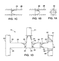
- European Patent Application 293 756 A2 by Halar, et al. discusses the problems associated with AA formation. According to Halar, et al., a high level of AA is generated by non-uniform thermal degradation of PET as it flows through manifold channels. This phenomenon is demonstrated in Figs. 1(a), 1(b), and 1(c), in which the velocity profile 20 and the shear stress profile 24 are schematically depicted for the flow of resin through a channel 22 of a mold manifold.
- the resin flows faster at the center of the channel where the shear stress is minimum, thus forming boundary layers that are symmetrical across the flow.
- the temperature profile is similar to the shear stress profile, i.e., the temperature of the resin is minimum at the center of the channel.
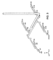
- the resin flow does not follow a straight path, as shown in Figs. 1(b) and 1(c), but rather makes one or more angular turns through a series of branch channels that simultaneously feed a plurality of cavity spaces (see Fig. 3). As indicated in Fig.
- Halar, et al. teaches that different asymmetrical profiles in different melt channels of a high cavitation mold cause AA differences in molded parisons. According to Halar, et al., the AA level can be minimized and made more uniform by providing static mixers within the melt channels of the mold manifold. Unfortunately, however, the static mixers induce a pressure drop and an increase in shear stress.
- U.S. Patent No. 5,421,715 issued to Hofstetter, et al. discloses the use of static metallic elements called spokes in the manifold channels to create turbulence and homogenize the temperature distribution across the flow, thus reducing the AA leveL
- the spokes of Hofstetter, et al. are no different than the static mixer of Halar, et al. and thus do not represent the ideal solution. In summary, providing mechanical obstructions within the melt channel may more uniformly redistribute the AA level among the injection cavities, but doing so creates additional problems.
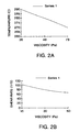
- FIGs. 2(a) and 2(b) depict the temperature versus viscosity and shear rate versus viscosity graphs for a typical molten resin.
- this device redirects the outer boundary layer of resin, which is more thermally degraded that the central layer, in a balanced proportion among several melt channels. Because this device works differently than a static mixer, it does not induce a pressure drop. However, the "melt flow redistributor" is relatively difficult to assemble and service.
- a third application of the present invention combats a phenomenon known as dip.
- the dip is an uneven or unfilled portion within a coinjected layer.
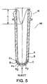
- Fig. 5 illustrates the dip phenomenon occurring in a typical three-material (A-B-C) five-layer (A1-A2-B1-B2-C) PET preform 46.
- a dip of length L appears in the neck portion N of the preform 46.
- Three resins A-B-C are either sequentially or simultaneously coinjected using conventional injection means to form a five-layer blowable preform.
- the dip is unacceptable because one resin (usually the barrier) does not fully fill the space in the neck area partially occupied by the other resin (virgin, etc.).
- the dip is believed to be caused by the formation of boundary layers within a manifold. These boundary layers cause non-uniform temperature and viscosity profiles across a flow of molten resin, which in turn causes dip.
- the dip may be improved by providing static mixers within the melt channels, but as mentioned previously, such static mixers create
- the present invention overcomes the AA, non-uniform filling, and dip problems by replacing or supplementing conventional coil or band heaters with film heaters strategically disposed along the melt channels and individually controlled to provide the desired heat profile.
- thin film heaters placed adjacent to each comer 23 can be controlled to provide more heat to the resin flow than thin film heaters placed adjacent zone 22 of the melt channels in order to provide a constant temperature profile throughout the melt channel.
- the thin film heaters can change the velocity, temperature, and shear stress profiles of the flowing resin according to the specific geometry of each melt channel and angle of intersection with adjoining melt channels.
- a fourth application of the present invention relates to various improvements of current injection molding components that, in most instances, do not provide an optimum temperature profile in a flow before the molten resin enters the mold cavity space.
- Examples of such components that would benefit from application of the present invention include coinjection hot runner nozzles, edge gating nozzles, tips of injection nozzles, nozzle-manifold interfaces, rim gating nozzles, mold gate inserts, etc.
- Fig. 6 is a schematic cross section showing a high cavitation mold sprue bushing 62, manifold 64, and hot runner nozzles 66 which are heated using thin film heaters 63, 65, and 67, respectively.
- Each thin film heater comprises an active film made of a thin film, electrically conductive material sandwiched between assorted passive thin film materials.
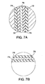
- the thin film heater is internally located so as to directly contact the molten resin, and the thin film heater 62 may comprise (as shown in Fig. 7(a)), in order starting from the channel, a wear resistive film 72, an electrically insulative film 74, the electrically resistive heater film 76, another layer of electrically insulative film 78, and finally a thermal insulative film 79.
- the thermally insulative film may be omitted.
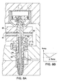
- Fig. 8(a) shows an improved design of an injection mold in which the manifold 80, manifold bushing 82, and hot runner nozzle 84 are individually heated using thin film electrical heaters 81, 83, and 85, respectively. Because a thin film heater 87 may be located inside the nozzle body and in contact with the molten resin, no temperature drop occurs in the upper portion A of the hot runner nozzle, as shown by the broken line in Fig. 8(b).
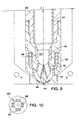
- Fig. 9 shows an improved design of a hot runner nozzle tip in accordance with an embodiment of the present invention.
- Active and passive thin film elements are located inside the hot runner nozzle body 90 along the melt channel 92 and in close proximity to the mold gate area 94.
- the active thin film elements are heaters 91, 93, 95, and 97 for maintaining the resin at an optimum temperature.
- the thin film heaters confer several other significant advantages. For example, the thin film heaters are easy to locate in areas that are not accessible to coil heaters, such as in the immediate vicinity of the mold gate.
- the thin film heaters 95 are located along diverter channels of the nozzle tip.
- the thin film heaters 97 may also be located on the inner periphery of the mold gate insert 98 in order to heat the mold gate more . effectively. Locating thin film heaters within the mold gate insert provides additional advantages with respect to "color change" preparation. As is generally known in the art, when changing resins to mold an identical piece but of a different color, one should "flush" the first resin from the nozzle channels. By locating a thin film heater 97 on the inner periphery of the mold gate insert, the insert may be heated to facilitate flushing of the gate channel. Also, heaters may be combined with thermocouples as shown at 97 and 99.
- the mold gate insert further may comprise a thin film pressure sensor 96 and/or thin film temperature sensors (not shown).
- Fig. 10 shows the disposition of pressure sensors 96 and thermocouple 100 around the nozzle tip 90°. As shown in Fig. 11, the individual components of the hot runner nozzle and mold gate insert are easily removed, manufactured, and serviced.
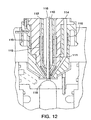
- Fig. 12 shows a coinjection nozzle with thin film heaters in accordance with yet another embodiment of the present invention.
- At least one thin film heater may be disposed around or inside the housing of each coinjection channel to better control the temperature of each resin.
- a three channel nozzle is shown wherein the channel 110 carries resin A, channel 112 carries resin B, and channel 114 carries resin C.
- the valve gate stem 116 selectively shuts off communication between the nozzle channels and a cavity space 118.
- Thin film heaters 111, 113, and 115 are respectively located inside the channels.
- heater 111 may be sufficient to heat both resins A and B. Because the thin film heaters will directly contact the flow of molten resin, a wear resistive film may be provided directly adjacent to the flow.
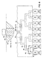
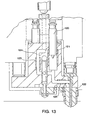
- Fig. 13 shows a molding machine including shooting pots 120 for metering the amount of resin delivered to the hot runner nozzle 122.
- Shooting pots are typically used when injecting parts that must meet stringent weight requirements, such as the accurately measured layers commonly required for a coinjection mold.
- thin film heaters 121 is located in the shooting pot area to heat the shooting pot area independently from other thin film manifold heaters such as heaters 123, 125 disposed on manifold 124. Additionally, thin film thermal sensors may be located in the shooting pot area.
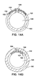
- Figs. 14(a) and 14(b) show preferred means for removably attaching a thin film heater to either the outside or the inside of a hot runner nozzle, respectively.
- the thin film heater is deposited on a flexible thin, band substrate that may display spring-like characteristics. A thin film heater attached in this manner may be easily replaced in the event of a failure.
- thin film heater 132 is disposed outside of nozzle 130 and may comprise, for example, electrically insulated layer 132, electrically conductive layer 134, and electrically insulated layer 136.
- a connector 138 fits within a channel of the nozzle 130 and restrains the two ends of the resilient heater 132. Such construction can provide localized heat to the resin and melt channel 139.
- the heater 132 is disposed inside nozzle 130 and may also comprise the layers 132, 134, and 136.
- a wear layer (now shown) can also be provided between layer 132 and the melt channel 139 to present wear on the heater 132.
- the heating elements in layer 134 may extend only partially around the circumference of the nozzle, and be in any configuration (spiral, planar, stripped, herringbone, annular, etc. Also, the heating elements may extend to different lengths along the axial direction of the nozzle.
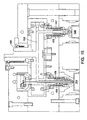
- Fig. 15 shows an injection molding machine having both a hot runner valve gate and a hot runner thermal gate.
- the molten resin precedes from the machine injection nozzle (not shown) through the sprue bushing 150 into the manifold 152 and into the melt channel of each nozzle.
- the molten resin flowing through the bushing and manifold may be maintained at the optimum temperature by using well known band or coil electric heaters.
- the molten resin is then injected through each of the nozzles into respective mold cavities 154 and 156.
- the hot runner valve gate 158 has a thin film heater 159 associated therewith to maintain the molten resin at the precise, desired temperature as it passes through the valve gate 158 into the cavity 154.
- the hot runner thermal gate 157 has a thin film heater 155 associated therewith to precisely control the temperature of the molten resin as it flows into cavity 156.
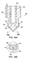
- Fig. 16(a) is a schematic cross-section of a valve gated hot runner nozzle where a film heater is deposited directly on the tip portion of the stem, and a film thermocouple is deposited directly on the end of the stem.
- the valve-gated nozzle 160 has a nozzle tip 162 which fits within mold plate 164 abutting the mold plate 164' containing the mold cavity space 166.
- the movable valve stem 168 has a film heater 167 deposited on the outer surface thereof in a pattern, for example, as shown in Fig. 16(a).
- a thermocouple is deposited on the end of valve stem 168 for accurate temperature measurement precisely at the valve gate itself.
- the film heater 167 may be coupled to electrical contacts 161 through terminals 163.
- electrical contacts 165 are disposed to contact terminals 169.
- the electrical contacts are coupled to a mold control processor 1000, such as that described in the Schmidt patent discussed above.
- Fig. 17 is a cross-sectional view of the film heater 167 of Fig. 16(a). Closest to the valve stem 168 is a layer 171 made of electrical insulative material. Next is a layer 173 which comprises the electrically resistive material forming the heating element. On the outside is layer 175 which comprises an electrically insulative material that also has good thermal transmission characteristics.
- Fig. 18(a) is a schematic cross-sectional drawing showing film heater 181 disposed on a bottom exterior surface of nozzle tip 180. As shown in Fig. 18(b), the film heater 181 may have a resistive pattern which surrounds the melt channels 182 and 183, as shown. The heater terminals 184 and 184' may be connected to electrical contacts (not shown).
- the nozzle tip 180 may also have a heater plug 190 (to be described below) which has a film heater 191 disposed on an outer surface thereof.
- the heater plug 190 is disposed in the melt channel 186 of the nozzle tip 180.
- Both film temperature sensors may also be deposited on any convenient surface of the nozzle tip 180 to monitor the temperature of the molten resin in the melt channel 186.
- the temperature sensor is a film thermocouple disposed in direct contact with the molten resin very close to the mold gate orifice.
- the nozzle tip 180 includes electrical connectors for the thermocouple and the heater which are attached to the nozzle body by a fast removal mechanism, such as a bayonet mechanism, which allows rapid assembly and removal of the tip without having to disconnect any wiring.
- a fast removal mechanism such as a bayonet mechanism
- Fig. 19(a) is a schematic cross-section of a film heater plug 190 which is a convenient and easy way to apply film heaters and film sensors to the melt channels of injection molding machines.
- Plug 190 comprises a metal plug 192 having a film heater 193 disposed on an interior surface thereof adjacent the melt channel 194.
- the heater 193 comprises an inner wear resistive layer 195, an electrically resistive layer 196, an electrical insulation layer 196, and a thermal insulation layer 198.
- the advantage of such a construction is that the plug 190 can be made small and replaceably positioned at any point in the melt channel.
- the plug can be used at any located in alignment with the melt channel of the mold, for example, in the manifold, in the hot runner housing or in the nozzle tip.
- the melt channel can be constructed complementary structure so that such heater plugs can be placed at any convenient location along the melt channel. Moreover, such plugs can be linear, T-shaped, or angled to fit any location along the melt channel. Since it is much easier to dispose a flexible film heater on the interior surface of a small, replaceable heater plug, the cost of disposing that heaters on the inside surface of a long melt channel manifold (as depicted in Fig. 3) can be avoided.
- Fig. 19(b) depicts another embodiment of the heater plug 190 in which the heater 193 is disposed on the outer surface 192.
- the inner layer 195' comprises a dielectric with good thermal transmitting characteristics
- layer 196' is the electrically resistive heating element
- layer 197' is a thermal insulator.
- a wear resistant layer may be deposited on the outside of the layer 197'.
- a wear resistant layer 198' may be deposited on the inside of the plug 192 to enhance resistant to the wear of the molten resin.
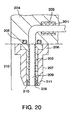
- Fig. 20 shows the application of removable heater plugs 201 and 202 within an injection molding machine.
- Heater plug 201 has film heater 203 on the exterior surface thereof and is disposed within manifold 204, which, for example, may also be heated by conventional manifold heater 205.
- the heater plug 202 is disposed within nozzle head 206 and nozzle body 207 and has a wear resistant layer (sleeve) 208 disposed on an interior surface thereof adjacent the melt channel 209.
- a film heater 210 is disposed on an exterior surface of the heater plug 202 adjacent the nozzle tip 211.
- the nozzle housing 212 is preferably made of a thermal insulation material.
- the heater plugs 201 and 202 are preferably made of a highly thermally conductive material such as CuBe. Since the heater plugs 201 and 202 are modular and removable, they may be easily replaced for repair or for the molding of different types of plastic resin.
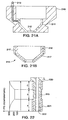
- Fig 21(a) is a schematic cross-section of a mold gate insert 210 having an internal film heater 211 disposed on an inside surface adjacent the nozzle tip (not shown) and the mold gate orifice 212. Since the mold gate insert 210 is removable, a connector 213 is disposed on a surface thereof to carry the electrical contact wires to the film heater 211. The connector 213 will mate with a like connector in the nozzle housing or the mold plate (not shown) so that the entire mold gate insert 210 is quickly and easily replaceable.
- Fig. 22(b) is a schematic cross-section of a mold gate sleeve 215 wherein the mold gate body 216 has a film heater 217 disposed on the one or more of the outer surfaces thereof.
- the mold gate sleeve is easily replaceable, it is simple to replace a defective heater or to change the heating capacity of the heater for different types of resin.
- Fig. 22 is a schematic cross-section of a heater plug 220 having a film heater disposed on the outer surface thereof.
- the film heater layer as different thicknesses in areas A, B, and C to provide an engineered temperature profile, as depicted in the left-hand portion of Fig. 22.
- This may be used, for example, in molding applications where portions A and C are located adjacent mold plates which are cooled during the molding process. This way, the molten resin flowing within the melt channel 222 will be maintained at a constant temperature.
- a high wear resistive sleeve 223 is disposed on the interior surface of the heater plug 220.
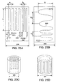
- Fig. 23 (a) is a schematic view of a thin film heater according to the present invention having two rectangular patterns of heating elements.
- Heater 231 has an element with a length L and a pitch P1.
- Heater 232 has a heating element with the same length L, but with a different pitch P2.
- the contact terminals have a length Lt and a width T adapted to easily engage electrical contacts on the melt channel structure where the heater is to be mounted.
- Fig. 23(b) is a schematic of a heater having a serpentine shaped heating element 235 with contact terminals at different ends thereof.
- Fig. 23 (c) shows a film heater bent so as to be disposed on the inside of a melt channel
- Fig 23(d) shows such a heater bent on the outside of a melt channel.
- Film temperature sensing elements have been disclosed in, for example, US Patent 5,215,597 issued to Kreider, US Patent 5,573,335 issued to Schinazi, NASA Report E-7574 of February 1993 by R Holanda and NASA Report E-9080 of August 1994 by L.C. Martin et al., all of which are all incorporated herein by reference..
- Any film temperature sensing device such as thermistors, other semiconductor based devices, or resistance temperature detectors (RTD) are encompassec by the scope of the current invention.
- RTD resistance temperature detectors
- the current invention also encompasses a thin film RTD as another preferable alternative to a film thermocouple, because it offers the advantage of being made of a single thin film material that is easier to deposit and etched.
- thermocouple that meet the current thermocouple standards (such as ANSI), and that can be deposited on the support base of the mold part.
- a major design target for the film thermocouple is to select two dissimilar materials for the wires that are either identical or close to the resistive material of the thin film heater.
- the following commercial data published by Insulation Seal Inc. and SRS Corp. show the material selection and characteristics for several standard thermocouples that can be also used as guidelines to manufacture film thermocouples. ANS I Thermocouple Pair Materials & Polarity TC Temperature (max.) Medium Std.
- the film thermocouple is made using well known microlithographic techniques that insure a very high dimensional accuracy, excellent adhesion of the themocouple to the substrate and connection between the two dissimilar materials.
- Another advantage of the microlithographic technique is that a batch of thermocouples can be simultaneously manufactured in order to ensure that the thickness of the deposited alloy is the same for several temperature sensing elements that will be mounted in a high cavitation mold.
- Another advantage is that, with no extra cost and within the same space, a "back up" or a reference thermocouple can be actually deposited close to the actual thermocouple. In this manner, if for whatever reason the current thermocouple fails to respond, the back up can be activated, without interrupting the molding process or servicing the mold.
- a thin film (R-class) thermocouple is made of Platinum-13% Rhodium and Platinum and is manufactured in a class 1000 Clean Room using the well known sputtering process. Depending on the location of the thin film wires to the lead wires connections are made using the well known parallel-gap welding process.
- This thermocouple can be located anywhere along the melt channel as it can withstand temperatures in excess of 1,000 °C.
Abstract
Description
- The present invention relates to an improvement in heat management and process control for a molding process and, more particularly, to the use of active and/or passive film heating and/or sensing elements located along a flow channel of molten resin to a mold cavity space.
- In an injection molding process, it is important to maintain a resin in a molten state as it flows from a nozzle of an injection molding machine, through a mold sprue bushing, a mold manifold, a hot runner nozzle, and into a mold cavity space, where the resin cools to form an injection-molded article. Additionally, the shear stress profile of the flow of resin must be monitored and managed to insure proper filling of the cavity space. This is especially important in the area close to the mold gate because the temperature there is rapidly cycled between hot and cold conditions before the molded article is removed from the cavity. Temperature control issues are also very important when molding certain thermally-sensitive materials such as PET in a multicavity mold or when molding articles made of different materials that are injected through a single hot runner nozzle. Accordingly, much effort has been directed towards improving heat management and process control in the injection molding process, particularly in the mold manifold and hot runner nozzle. To date, several methods and means have been employed with varying degrees of success. Included among the methods and means commonly employed are heat pipes, high frequency induction heaters, microwave heaters, ceramic heaters, infrared radiation heaters, electrical heaters, etc. Such electric heaters include coils, band, or cartridge heaters which are used to heat the molten resin inside the screw barrel, in the machine nozzle, in the manifold, in the hot runner nozzle, and in the mold gate area.
- U.S. Patent No. 5,645,867 issued to Crank, et al. illustrates the current state of the art with respect to heating the mold manifold. Crank, et al. teaches heating the manifold by disposing infrared radiation heaters on an outer surface of the manifold. However, as is typical of such prior art manifold heating apparatuses, a significant proportion of the heat generated by the heaters is wasted heating the entire manifold block rather than directly heating the resin flowing in a melt channel contained therein.
- U.S. Patent No. 5,614,233 issued to Gellert discloses a state of the art heater for a hot runner nozzle, in which a helical electrical heater is embedded in a spiral groove that surrounds the hot runner nozzle. The heater comprises a resistive wire enclosed in a refractory powder electrical insulating material such as magnesium powder oxide. The helical portion of the heater is press-fitted and reshaped into place in the spiral groove. However, the disclosed heater heats both the hot runner nozzle body and the melt channel contained therein, a relatively inefficient heating arrangement. Additionally, manufacturing the spiral groove and assembling the heater therein is time-consuming and costly.
- The foregoing problems with prior art heaters are particularly evident in coinjection and multiinjection mold manifolds and hot runner nozzles. For example, U.S. Patent No. 4,863,665 issued to Schad, et al. discloses the use of a single electrical heater attached to the outer surface of a hot runner nozzle to heat three melt channels simultaneously. Schad, et al., however, faces several drawbacks. First, less heat is transmitted to the inner channels than to the outer channels. Second, the heat supplied to each channel cannot be varied according to the size of each channel and the rheological characteristics of the resin flowing therein.
- European Patent 312 029 B1 issued to Hiroyoshi discloses a heater made of an insulating ceramic film that is flame-sprayed on the outer surface of the nozzle which introduces the resin into the molding machine. The heater may be a continuous area heater completely covering the nozzle, a heater made of a plurality of longitudinal strips, a thin film heater made of helical strips, or a two piece independent heater with more power supplied to the nozzle where it contacts the mold. However, the heater disclosed in Hiroyoshi has several significant drawbacks that militate against its application to a mold manifold or hot runner nozzle. First, the Hiroyoshi heater is not removable and thus requires replacement of the entire element when the heater bums out. Second, the heater inefficiently heats the entire machine nozzle body rather than directly heating the molten resin. Third, the heater cannot provide a profiled temperature gradient across the flow of molten resin, an important feature for managing shear stress in the flow of molten resin. Finally, the thickness of the disclosed heater is 0.5 to 2mm, which is acceptable for application to the outer surface of the machine nozzle, but intolerable for application to the interior of a melt channel in a mold manifold or hot runner nozzle.
- U.S. Patent Nos. 5,007,818 and 5,705,793 disclose the use of heaters which are deposited directly on the flat surface of the cavity mold. U.S. Patent No. 5,504,304 discloses a removable ceramic heater made of a ceramic paste whose thickness is hard to control. Such heaters as these do not provide for intimate contact with the nozzle body or the nozzle tip and thus reduce heat transfer and increase heat loss. Japanese Patent Application No. 55161626 describes a hot runner for directing a flow of hot molten material from an inlet passage (defined by an inner cylinder) to a cavity space. The hot runner nozzle and the inlet passage define a melt channel, and a tubular heater is provided around the melt channel, insulated therefrom by the inner cylinder. Reference may also be made to the following U.S. Patents which disclose heater technology; 5,155,340; 5,488,350; 4,724,304; 5,573,692; 5,569,398; 4,739,657; 4,882,203; 4,999,049; and 4,340,702.
- Accordingly, there is a need in the art for a method and means of heating a melt channel of mold manifold and hot runner nozzle in a manner that is efficient in terms of energy, space and location.
- There is an additional need in the art for an efficient method and means of providing an appropriate amount of heat to each melt channel in a coinjection or multiinjection hot runner nozzle based on the localised size and shape of each melt channel and the rheological characteristics of the resin flowing therein.
- It is an object of the present invention to provide method and apparatus for efficient heat and flow management of molten resin within the melt channel of a mold manifold and a hot runner nozzle.
- According to the present invention, there is provided apparatus for directing a flow of molten resin from a nozzle of an injection moulding machine to a cavity space defined by a mould, the apparatus comprising:
- a manifold having formed therein an inlet passage for receiving the flow of molten resin from the nozzle of the injection moulding machine;
- hot runner nozzle for directing the flow of molten resin from the manifold inlet passage to the cavity space, the hot runner nozzle and manifold inlet passage together defining a melt channel; characterised in that the apparatus comprises an active thin film element or a passive thin film element disposed within the melt channel.
-
- In one embodiment of the present invention, there is provided apparatus for directing a flow of molten resin supplied by an injection molding machine to a cavity space defined by a mold includes a hot runner nozzle having a plurality of melt channels for directing the flow of molten resin supplied by the injection molding machine to the cavity space. A plurality of active/passive thin film elements is disposed substantially adjacent to each melt channel for supplying heat to the flow of molten resin within that melt channel.
- A cavity plate may be provided, and a core plate is then disposed relative to the cavity plate to define a cavity space. The hot runner nozzle preferably includes a plurality of melt channels, each melt channel directing one of multiple flows of molten resin supplied by the injection molding machine to the cavity space. An active or passive film element is disposed within each melt channel.
- These and other objects, features, and advantages can be better appreciated with reference to the following drawings, in which like reference numerals refer to the elements throughout.
- The present invention is described in conjunction with the accompanying drawings, in which:
- Fig. 1(a) is an axial cross sectional view of a circular melt channel of a mold manifold;
- Fig. 1(b) is a longitudinal cross sectional view of the melt channel of Fig. 1(a) schematically depicting the velocity profile of the resin as it flows through the melt channel;
- Fig. 1(c) is a longitudinal cross sectional view of the melt channel of Fig. 1(a) schematically depicting the shear stress profile of the resin as it flows through the melt channel;
- Fig. 1(d) is a cross sectional view of a manifold, including a network of melt channels, schematically depicting variations in the shear stress profile of the resin as it flows through the manifold;
- Fig. 2(a) is a graph showing the relation between temperature and viscosity at a constant shear rate;
- Fig. 2(b) is a graph showing the relation between shear rate and viscosity at a constant temperature;
- Fig. 3 is an elevated perspective view of a mold manifold showing a plurality of 90° turns;
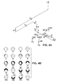
- Fig. 4(a) is a schematic representation of a mold manifold;
- Fig. 4(b) is a series of axial cross sectional views of the mold manifold of Fig. 4(a) showing uneven formation and distribution of boundary layers;
- Fig. 5 is a longitudinal cross sectional view of a three-material, five-layer PET preform showing incomplete penetration of one of the layers, a phenomenon known as DIP;
- Fig. 6 is a schematic cross section of a high cavitation mold comprising thin film manifold and hot runner heaters in accordance with an embodiment of the present invention;
- Fig. 7(a) is a schematic cross section showing the layers of thin film
elements in the
thin film heater 62 of Fig. 6; - Fig. 7(b) is a schematic cross section showing the layers of thin film
elements in the
thin film heater 65 of Fig. 6; - Fig. 8(a) is a cross sectional view of an improved hot runner nozzle design in accordance with another embodiment of the present invention;
- Fig. 8(b) is a chart showing the lack of temperature drop in the upper portion of the hot runner nozzle;
- Fig. 9 is a cross sectional view of an improved nozzle tip and mold gate insert in accordance with an yet another embodiment of the present invention;
- Fig. 10 is a schematic cross sectional view of the nozzle tip shown in Fig. 9;
- Fig. 11 is a cross section of the components of the Fig. 9 nozzle;
- Fig. 12 is a cross sectional view of a coinjection nozzle comprising thin film heaters in accordance with another embodiment of the present invention;
- Fig. 13 is a cross sectional view of a molding machine including shooting pots and comprising thin film elements within the shooting pot;
- Fig. 14(a) is an axial cross sectional view of a melt channel having a thin film heater removably attached to its outer periphery;
- Fig. 14(b) is an axial cross sectional view of a melt channel having a thin film heater removably attached to its inner periphery;
- Fig. 15 is a schematic cros sectional view of a molding machine having both a valve gate and a thermal gate;
- Fig. 16(a) is a schematic cross section of a valve-gated nozzle having a thin film heater;
- Fig. 16(b) is a schematic view of the thermocouple on the end of the valve stem of Fig. 16(a);
- Fig. 17 is a schematic cross section of the film heater of Fig. 16(a);
- Fig. 18(a) is a schematic cross section of a nozzle tip having internal and external film heaters;
- Fig. 18(b) is an end view of the film heater on the tip of the nozzle of Fig. 18(a);
- Fig. 19(a) is a schematic cross section of a nozzle plug having an internal film heater;
- Fig. 19(b) is a schematic cross section of a nozzle plug having an external film heater;
- Fig. 20 is a schematic cross section of a manifold and nozzle which have film heaters;
- Fig. 21(a) is a schematic cross section of a mold gate insert having a film heater;
- Fig. 21(b) is a schematic cross section of a mold gate sleeve having a film heater;
- Fig. 22 is a schematic cross section of a mold plug having a film heater with different widths;
- Fig. 23(a) is a schematic view of the resistive patterns on a thin film heater:
- Fig. 23(b) is a schematic view of the resistive patterns on another film heater;
- Fig. 23(c) shows a film heater disposed inside a melt channel; and
- Fig. 23(d) shows a film heater disposed on the outside of a melt channel.
-
- The advantageous features of the present invention will be described with respect to a plastic injection molding machine utilizing thin film heater and sensor technology. Of course, the invention is not limited to such embodiments, but may be applied in any molding technology within the scope of the attached claims.
- As described below, an injection molding system according to the present invention may include electrical heaters and temperature sensors to better manage and control the flow of the molten resin between in the injection machine nozzle and the mold cavity space. Thus, the present invention comprises active and/or passive film elements which may be deposited directly on the surface of the mold elements (such as in the manifold and/or adjacent the mold gate area) to precisely manage the temperature profile in the moving, molten resin. For some applications, these film elements may be deposited directly on the nozzle housing and/or the nozzle tip, on a runnerless probe, on a valve stem, or on a surface of a mold gate insert. In other cases, the film elements may be deposited on a removable heater plug which is located at one or more predetermined positions in the molding system. Preferably, the active film element comprises a film heater, and the passive film element comprises a thermal sensor (e.g., a thermistor or thermal couple) and/or a pressure sensor. The film elements may be single layer elements, but preferably comprise a sandwich of several film layers having different electrical, thermal, and wear characteristics. One film layer will usually be made of an electrically highly-resistive material. Depending upon the particular molten resin and the particular molding process characteristics, the film can be either a "thin" or "thick" element which is preferably deposited using chemical deposition, vapor deposition, film spray techniques, or equivalents thereof. The film heating and sensing elements may also comprise flexible substrates which are trimmed and installed, as needed, at any location in the injection molding machine.
- Also within the scope of the present invention is the use of such film elements in conjunction with the known heaters described above. By carefully selecting the appropriate film heating elements (when used in conjunction with or in place of known heaters) fine adjustments may be made to the molten resin temperature gradient and profile to provide precise heat flow control. Such precise control can be effected before the molten resin enters the heated space, thus providing constant (or precisely-managed) viscosity and velocity of the melt flow.
- If the film heater is directly deposited, this can also eliminate the air gap between the heater and the heated surface thus providing intimate and direct contact for improved temperature transfer between the heater and the heated surface, to achieve energy savings and longer heater life. Also, the direct deposition of the film heater makes the mold elements themselves simpler to design and manufacture since they may be made smaller and more energy efficient and use less space within the mold machine itself. Furthermore, the quality of the molded articles is significantly improved because of the precise management of the heat flow in the injection molding machine. Additionally, when molding an article that has several resin layers deposited at once, the use of film heater elements will allow each layer to having a uniform thickness and length. In the case of molding PET preforms using the film heaters described below, the acetaldehyde level is lower and is more uniformly distributed across the cavities of the multi-cavity mold. This is because the film heaters are located adjacent the melt channels and can be individually controlled and activated so that the temperature is very uniform across the entire manifold.
- Also, by improving the heating control at the mold gate area, the sprue gate (vestige) of the molded preform may be made very small with substantially no crystallinity penetrating the preform wall.
- Further, the use of the film heaters according to the present invention will provide significant advantages when molding two different color resins through the same nozzle. Precise heat control will allow an abrupt transition between the different colors, increasing the quality of the final product and reducing wastage.
- Thus, the film heaters according to the present invention are in intimate contact with the surface to be heated, and can provide faster heating response time, lower temperature inertia, are small enough to be placed in many different areas of the mold, and can provide a tightly constrained temperature profile which leads to faster molding, higher quality in the produced articles, smaller machine parts, reduced energy consumption, and longer machine life.
- By utilizing film sensors according to the present invention, more precise temperature management and control of the entire process can be achieved. Such film sensors can be placed in many more locations than known thermal couples, and are easily installed, maintained, and monitored. Therefore, process feedback and control is also enhanced according to the film sensors of the present invention.
- The present embodiments locate compact active and/or passive film elements along a melt channel from, for example, a sprue bushing to a mold cavity space to improve heat and flow management therein. The active elements, which may be fabricated using advanced thin film technologies, are compact, reliable, stable, and energy efficient. Advantageously, the active elements may be located near or in direct contact with a flow of molten resin. The active elements may be any of a thin film heater, thermistor, thermocouple, resistance temperature detector, pressure sensor, gas sensor, optical guide leakage sensor, or combinations and equivalents thereof. The passive elements, which also may be fabricated using thin film technologies, interact with the active elements and may be made of electrical and thermal insulative materials and/or wear resistant materials. Preferably, the passive elements are in direct contact with the flow of molten resin to improve the laminar flow thereof. Employing these thin film elements optimizes heat management and overall control of the injection molding process. In particular, the thin film elements may directly heat the resin in the manifold or hot runner nozzle according to local and customized needs. Further, the use of thin film elements favorably impacts material selection and component size along the melt channel.
- The present embodiments also provide an innovative mold controller and logic operation means either coupled to or embedded in the mold. The mold controller and logic operation means are physically independent from, but in communication with, the controller and microprocessor of the injection molding machine. In this regard, reference is made to U.S. Patent No. 5,320,513 issued to Schmidt.
- Schmidt discloses a mold integrated circuit board that connects the hot runner nozzle heaters and temperature sensors to the machine controller via a connector. According to the present embodiments, the printed circuit board of the mold disclosed by Schmidt further carries control and logic signals generated by a mold controller and/or a mold microprocessor. Thus, the end user of the mold will better be able to handle the processing parameters of the mold in conjunction with various injection molding machines. The mold-machine interface will allow either the mold, the machine, or both to be tuned for specific injection molding processing conditions. Also, the interface will reduce the complexity of the injection molding controls. Communication between the mold controller and the machine controller and/or between the active thin film elements and the mold controller may be accomplished by either wired or wireless means, with the latter further reducing the complexity of the wire connections.
- Mold heat management and process control depend on the specific application, the type of resin used, the mold manifold and hot runner nozzle design, and the number of mold cavities. The present embodiments could be applied to improve heat management and process control in several molding processes, three of which processes relate to high cavitation molding and, more particularly, to injection molding of blowable PET preforms.
- A first application of the present invention reduces and more uniformly distributes acetaldehyde ("AA") inherently generated in a mold during the injection process. European Patent Application 293 756 A2 by Halar, et al. discusses the problems associated with AA formation. According to Halar, et al., a high level of AA is generated by non-uniform thermal degradation of PET as it flows through manifold channels. This phenomenon is demonstrated in Figs. 1(a), 1(b), and 1(c), in which the
velocity profile 20 and theshear stress profile 24 are schematically depicted for the flow of resin through achannel 22 of a mold manifold. Due to themelt channel profile 26, the resin flows faster at the center of the channel where the shear stress is minimum, thus forming boundary layers that are symmetrical across the flow. The temperature profile is similar to the shear stress profile, i.e., the temperature of the resin is minimum at the center of the channel. In most molding applications, however, the resin flow does not follow a straight path, as shown in Figs. 1(b) and 1(c), but rather makes one or more angular turns through a series of branch channels that simultaneously feed a plurality of cavity spaces (see Fig. 3). As indicated in Fig. 1(d), when the resin flow through onechannel 21 is diverted 90° into several branches, such as the first twochannels inner comer 23 than theouter comer 25. At this stage, the shear stress andtemperature values 30 are higher near theinner comer 23 than thevalues 28 near theouter comer 25. This asymmetrical behavior further is enhanced and reduced respectively when the flow . again is diverted intochannels temperature profiles - Halar, et al. teaches that different asymmetrical profiles in different melt channels of a high cavitation mold cause AA differences in molded parisons. According to Halar, et al., the AA level can be minimized and made more uniform by providing static mixers within the melt channels of the mold manifold. Unfortunately, however, the static mixers induce a pressure drop and an increase in shear stress. U.S. Patent No. 5,421,715 issued to Hofstetter, et al. discloses the use of static metallic elements called spokes in the manifold channels to create turbulence and homogenize the temperature distribution across the flow, thus reducing the AA leveL The spokes of Hofstetter, et al. are no different than the static mixer of Halar, et al. and thus do not represent the ideal solution. In summary, providing mechanical obstructions within the melt channel may more uniformly redistribute the AA level among the injection cavities, but doing so creates additional problems.
- A second application of the present invention promotes more uniform filling of high cavitation molds by suppressing the thermal and viscosity boundary layers that typically form when a flow abruptly changes direction. Figs. 2(a) and 2(b) depict the temperature versus viscosity and shear rate versus viscosity graphs for a typical molten resin.
- If a manifold feeds several cavities, as shown in Fig. 3, the formation of boundary layers will cause asymmetrical temperature, shear stress, and velocity profiles for the flow of resin for each cavity, as shown in Figs. 4(a) and 4(b). This problem, also mentioned by Halar, et al., may be solved by using a "melt flow redistributor" such as that disclosed in copending U.S. Patent Application No. 08/570,333 by Deardurff, et al., assigned to the assignee of the current invention and incorporated herein by reference. The "melt flow redistributor" is located after a 90° turn in a melt channel. Thus positioned, this device redirects the outer boundary layer of resin, which is more thermally degraded that the central layer, in a balanced proportion among several melt channels. Because this device works differently than a static mixer, it does not induce a pressure drop. However, the "melt flow redistributor" is relatively difficult to assemble and service.
- A third application of the present invention, derived from the second application, combats a phenomenon known as dip. The dip is an uneven or unfilled portion within a coinjected layer. Fig. 5 illustrates the dip phenomenon occurring in a typical three-material (A-B-C) five-layer (A1-A2-B1-B2-C)
PET preform 46. A dip of length L appears in the neck portion N of thepreform 46. Three resins A-B-C are either sequentially or simultaneously coinjected using conventional injection means to form a five-layer blowable preform. The dip is unacceptable because one resin (usually the barrier) does not fully fill the space in the neck area partially occupied by the other resin (virgin, etc.). The dip is believed to be caused by the formation of boundary layers within a manifold. These boundary layers cause non-uniform temperature and viscosity profiles across a flow of molten resin, which in turn causes dip. The dip may be improved by providing static mixers within the melt channels, but as mentioned previously, such static mixers create additional problems. - The present invention overcomes the AA, non-uniform filling, and dip problems by replacing or supplementing conventional coil or band heaters with film heaters strategically disposed along the melt channels and individually controlled to provide the desired heat profile. For example, thin film heaters placed adjacent to each
comer 23 can be controlled to provide more heat to the resin flow than thin film heaters placedadjacent zone 22 of the melt channels in order to provide a constant temperature profile throughout the melt channel. Thus located, the thin film heaters can change the velocity, temperature, and shear stress profiles of the flowing resin according to the specific geometry of each melt channel and angle of intersection with adjoining melt channels. - A fourth application of the present invention relates to various improvements of current injection molding components that, in most instances, do not provide an optimum temperature profile in a flow before the molten resin enters the mold cavity space. Examples of such components that would benefit from application of the present invention include coinjection hot runner nozzles, edge gating nozzles, tips of injection nozzles, nozzle-manifold interfaces, rim gating nozzles, mold gate inserts, etc.
- Improved components embodying film heaters and insulation layers will now be discussed with reference to several U.S. patents, each of which is assigned to the assignee of the present invention and incorporated herein by reference.
- Fig. 6 is a schematic cross section showing a high cavitation
mold sprue bushing 62,manifold 64, andhot runner nozzles 66 which are heated usingthin film heaters thin film heater 62 may comprise (as shown in Fig. 7(a)), in order starting from the channel, a wearresistive film 72, an electricallyinsulative film 74, the electricallyresistive heater film 76, another layer of electricallyinsulative film 78, and finally athermal insulative film 79. In some applications, the thermally insulative film may be omitted. - Fig. 8(a) shows an improved design of an injection mold in which the manifold 80,
manifold bushing 82, andhot runner nozzle 84 are individually heated using thin filmelectrical heaters thin film heater 87 may be located inside the nozzle body and in contact with the molten resin, no temperature drop occurs in the upper portion A of the hot runner nozzle, as shown by the broken line in Fig. 8(b). - Fig. 9 shows an improved design of a hot runner nozzle tip in accordance with an embodiment of the present invention. Active and passive thin film elements are located inside the hot
runner nozzle body 90 along themelt channel 92 and in close proximity to themold gate area 94. The active thin film elements areheaters - In the illustrated embodiment, the
thin film heaters 95 are located along diverter channels of the nozzle tip. Thethin film heaters 97 may also be located on the inner periphery of themold gate insert 98 in order to heat the mold gate more . effectively. Locating thin film heaters within the mold gate insert provides additional advantages with respect to "color change" preparation. As is generally known in the art, when changing resins to mold an identical piece but of a different color, one should "flush" the first resin from the nozzle channels. By locating athin film heater 97 on the inner periphery of the mold gate insert, the insert may be heated to facilitate flushing of the gate channel. Also, heaters may be combined with thermocouples as shown at 97 and 99. - The mold gate insert further may comprise a thin
film pressure sensor 96 and/or thin film temperature sensors (not shown). Fig. 10 shows the disposition ofpressure sensors 96 andthermocouple 100 around thenozzle tip 90°. As shown in Fig. 11, the individual components of the hot runner nozzle and mold gate insert are easily removed, manufactured, and serviced. - Fig. 12 shows a coinjection nozzle with thin film heaters in accordance with yet another embodiment of the present invention. At least one thin film heater may be disposed around or inside the housing of each coinjection channel to better control the temperature of each resin. In this embodiment, a three channel nozzle is shown wherein the
channel 110 carries resin A,channel 112 carries resin B, and channel 114 carries resin C. The valve gate stem 116 selectively shuts off communication between the nozzle channels and acavity space 118.Thin film heaters heater 111 may be sufficient to heat both resins A and B. Because the thin film heaters will directly contact the flow of molten resin, a wear resistive film may be provided directly adjacent to the flow. - Fig. 13 shows a molding machine including shooting
pots 120 for metering the amount of resin delivered to thehot runner nozzle 122. Shooting pots are typically used when injecting parts that must meet stringent weight requirements, such as the accurately measured layers commonly required for a coinjection mold. In accordance with the present invention,thin film heaters 121 is located in the shooting pot area to heat the shooting pot area independently from other thin film manifold heaters such asheaters manifold 124. Additionally, thin film thermal sensors may be located in the shooting pot area. - Figs. 14(a) and 14(b) show preferred means for removably attaching a thin film heater to either the outside or the inside of a hot runner nozzle, respectively. The thin film heater is deposited on a flexible thin, band substrate that may display spring-like characteristics. A thin film heater attached in this manner may be easily replaced in the event of a failure. In Fig. 14(a),
thin film heater 132 is disposed outside ofnozzle 130 and may comprise, for example, electrically insulatedlayer 132, electricallyconductive layer 134, and electrically insulatedlayer 136. Aconnector 138 fits within a channel of thenozzle 130 and restrains the two ends of theresilient heater 132. Such construction can provide localized heat to the resin and meltchannel 139. In Fig 14(b), theheater 132 is disposed insidenozzle 130 and may also comprise thelayers layer 132 and themelt channel 139 to present wear on theheater 132. Of course, the heating elements inlayer 134 may extend only partially around the circumference of the nozzle, and be in any configuration (spiral, planar, stripped, herringbone, annular, etc. Also, the heating elements may extend to different lengths along the axial direction of the nozzle. - Fig. 15 shows an injection molding machine having both a hot runner valve gate and a hot runner thermal gate. The molten resin precedes from the machine injection nozzle (not shown) through the
sprue bushing 150 into the manifold 152 and into the melt channel of each nozzle. The molten resin flowing through the bushing and manifold may be maintained at the optimum temperature by using well known band or coil electric heaters. The molten resin is then injected through each of the nozzles intorespective mold cavities runner valve gate 158 has athin film heater 159 associated therewith to maintain the molten resin at the precise, desired temperature as it passes through thevalve gate 158 into thecavity 154. Likewise, the hot runnerthermal gate 157 has athin film heater 155 associated therewith to precisely control the temperature of the molten resin as it flows intocavity 156. - Fig. 16(a) is a schematic cross-section of a valve gated hot runner nozzle where a film heater is deposited directly on the tip portion of the stem, and a film thermocouple is deposited directly on the end of the stem. The valve-
gated nozzle 160 has anozzle tip 162 which fits withinmold plate 164 abutting the mold plate 164' containing themold cavity space 166. Themovable valve stem 168 has afilm heater 167 deposited on the outer surface thereof in a pattern, for example, as shown in Fig. 16(a). Preferably, and as shown in Fig. 16(b), a thermocouple is deposited on the end of valve stem 168 for accurate temperature measurement precisely at the valve gate itself. - As shown schematically in Fig. 16(a), the
film heater 167 may be coupled toelectrical contacts 161 throughterminals 163. Likewise,electrical contacts 165 are disposed to contactterminals 169. The electrical contacts are coupled to amold control processor 1000, such as that described in the Schmidt patent discussed above. - Fig. 17 is a cross-sectional view of the
film heater 167 of Fig. 16(a). Closest to thevalve stem 168 is alayer 171 made of electrical insulative material. Next is alayer 173 which comprises the electrically resistive material forming the heating element. On the outside islayer 175 which comprises an electrically insulative material that also has good thermal transmission characteristics. - Fig. 18(a) is a schematic cross-sectional drawing showing
film heater 181 disposed on a bottom exterior surface ofnozzle tip 180. As shown in Fig. 18(b), thefilm heater 181 may have a resistive pattern which surrounds themelt channels heater terminals 184 and 184' may be connected to electrical contacts (not shown). - The
nozzle tip 180 may also have a heater plug 190 (to be described below) which has afilm heater 191 disposed on an outer surface thereof. Theheater plug 190 is disposed in themelt channel 186 of thenozzle tip 180. Both film temperature sensors (not shown), may also be deposited on any convenient surface of thenozzle tip 180 to monitor the temperature of the molten resin in themelt channel 186. Preferably, the temperature sensor is a film thermocouple disposed in direct contact with the molten resin very close to the mold gate orifice. - Preferably, the
nozzle tip 180 includes electrical connectors for the thermocouple and the heater which are attached to the nozzle body by a fast removal mechanism, such as a bayonet mechanism, which allows rapid assembly and removal of the tip without having to disconnect any wiring. In some instances, it is preferable to have two thermocouples placed close to each other so that if one is broken, the other one is still operative. - Fig. 19(a) is a schematic cross-section of a
film heater plug 190 which is a convenient and easy way to apply film heaters and film sensors to the melt channels of injection molding machines.Plug 190 comprises ametal plug 192 having afilm heater 193 disposed on an interior surface thereof adjacent themelt channel 194. Preferably, theheater 193 comprises an inner wearresistive layer 195, an electricallyresistive layer 196, anelectrical insulation layer 196, and athermal insulation layer 198. The advantage of such a construction is that theplug 190 can be made small and replaceably positioned at any point in the melt channel. The plug can be used at any located in alignment with the melt channel of the mold, for example, in the manifold, in the hot runner housing or in the nozzle tip. The melt channel can be constructed complementary structure so that such heater plugs can be placed at any convenient location along the melt channel. Moreover, such plugs can be linear, T-shaped, or angled to fit any location along the melt channel. Since it is much easier to dispose a flexible film heater on the interior surface of a small, replaceable heater plug, the cost of disposing that heaters on the inside surface of a long melt channel manifold (as depicted in Fig. 3) can be avoided. - Fig. 19(b) depicts another embodiment of the
heater plug 190 in which theheater 193 is disposed on theouter surface 192. In this instance, the inner layer 195' comprises a dielectric with good thermal transmitting characteristics, layer 196' is the electrically resistive heating element, and layer 197' is a thermal insulator. In some instances, a wear resistant layer may be deposited on the outside of the layer 197'. Likewise, a wear resistant layer 198' may be deposited on the inside of theplug 192 to enhance resistant to the wear of the molten resin. - Fig. 20 shows the application of removable heater plugs 201 and 202 within an injection molding machine.
Heater plug 201 hasfilm heater 203 on the exterior surface thereof and is disposed withinmanifold 204, which, for example, may also be heated byconventional manifold heater 205. - The
heater plug 202 is disposed withinnozzle head 206 andnozzle body 207 and has a wear resistant layer (sleeve) 208 disposed on an interior surface thereof adjacent themelt channel 209. Afilm heater 210 is disposed on an exterior surface of theheater plug 202 adjacent thenozzle tip 211. Thenozzle housing 212 is preferably made of a thermal insulation material. The heater plugs 201 and 202 are preferably made of a highly thermally conductive material such as CuBe. Since the heater plugs 201 and 202 are modular and removable, they may be easily replaced for repair or for the molding of different types of plastic resin. - Fig 21(a) is a schematic cross-section of a
mold gate insert 210 having aninternal film heater 211 disposed on an inside surface adjacent the nozzle tip (not shown) and themold gate orifice 212. Since themold gate insert 210 is removable, aconnector 213 is disposed on a surface thereof to carry the electrical contact wires to thefilm heater 211. Theconnector 213 will mate with a like connector in the nozzle housing or the mold plate (not shown) so that the entiremold gate insert 210 is quickly and easily replaceable. - Fig. 22(b) is a schematic cross-section of a
mold gate sleeve 215 wherein themold gate body 216 has afilm heater 217 disposed on the one or more of the outer surfaces thereof. Again, since the mold gate sleeve is easily replaceable, it is simple to replace a defective heater or to change the heating capacity of the heater for different types of resin. - Fig. 22 is a schematic cross-section of a
heater plug 220 having a film heater disposed on the outer surface thereof. However, the film heater layer as different thicknesses in areas A, B, and C to provide an engineered temperature profile, as depicted in the left-hand portion of Fig. 22. This may be used, for example, in molding applications where portions A and C are located adjacent mold plates which are cooled during the molding process. This way, the molten resin flowing within themelt channel 222 will be maintained at a constant temperature. Note that in this embodiment, a high wearresistive sleeve 223 is disposed on the interior surface of theheater plug 220. - Fig. 23 (a) is a schematic view of a thin film heater according to the present invention having two rectangular patterns of heating elements.
Heater 231 has an element with a length L and a pitch P1.Heater 232 has a heating element with the same length L, but with a different pitch P2. Thus, the same thin film element may provide different heating characteristics to contiguous areas of the melt channel. The contact terminals have a length Lt and a width T adapted to easily engage electrical contacts on the melt channel structure where the heater is to be mounted. - Fig. 23(b) is a schematic of a heater having a serpentine shaped
heating element 235 with contact terminals at different ends thereof. - Fig. 23 (c) shows a film heater bent so as to be disposed on the inside of a melt channel, and Fig 23(d) shows such a heater bent on the outside of a melt channel.
- The following materials, deposition technologies, and patterning methods are recommended for the various layers used to manufacture the compound film heater deposited directly on the mold elements or on a film heater plug (the thickness of these layers varies from less than 5 microns and up to 2-3 millimeters):
- electrical resistive materials: TiN ; tungsten, molybdenum, gold, platinum, copper, TiC, TiCN, TiAIN, CrN, palladium, iridium, silver, conductive inks
- electrical insulative materials : beryllium oxide; see also the materials disclosed in the US Patent 5,653,932 and US patent 5,468,141 both herein incorporated by reference.
- wear resistance materials: titanium, titanium alloys, chrome, electroless nickel, also see the materials disclosed in the US Patent 5,112,025 herein incorporated by reference.
- deposition technologies: ion plating, sputtering, chemical vapor deposition (CVD), physical vapor deposition (PVD), flame spraying.
- film patterning methods: etching through a mask; laser removal; wire masking, mechanical removal,
- Example for the heat requirement: Wattage Density 40-80 W/square inch at 240 V
See Fig. 13 - Zone A: 37 mm 150 W (tip)
- Zone B: 75 mm 50 W (center)
- Zone C: 34 mm 100 W (head)
- One or several heaters
- Patterning: laser removal; lathe; mask wire, etching
- Deposition: spattering
- Materials: platinum, tungsten, Molybdenum
-
- Film temperature sensing elements have been disclosed in, for example, US Patent 5,215,597 issued to Kreider, US Patent 5,573,335 issued to Schinazi, NASA Report E-7574 of February 1993 by R Holanda and NASA Report E-9080 of August 1994 by L.C. Martin et al., all of which are all incorporated herein by reference..
- Any film temperature sensing device, such as thermistors, other semiconductor based devices, or resistance temperature detectors (RTD) are encompassec by the scope of the current invention. Reference is made in this regard to US Patent 4,968,964 issued to Nagai et al., and the Platinum Resistance Temperature Detector (P-RTD) Catalogs of Heraeus that are incorporated herein by reference. The current invention also encompasses a thin film RTD as another preferable alternative to a film thermocouple, because it offers the advantage of being made of a single thin film material that is easier to deposit and etched.
- According to the current invention, it is preferable to select the materials for the film thermocouple that meet the current thermocouple standards (such as ANSI), and that can be deposited on the support base of the mold part. Accordingly, a major design target for the film thermocouple is to select two dissimilar materials for the wires that are either identical or close to the resistive material of the thin film heater. The following commercial data published by Insulation Seal Inc. and SRS Corp. show the material selection and characteristics for several standard thermocouples that can be also used as guidelines to manufacture film thermocouples.
ANS I Thermocouple Pair Materials & Polarity TC Temperature (max.) Medium Std. Error Type Copper (+) 350°C T Constantan (-) Iron (+) 750 °C +/- 2.2 °C J Constantan (-) Chromel (+) 900°C +/- 1.7 ° C E Constantan (-) Chromel (+) 1250°C +/- 2.2°C K Alumel (-) Platinum 13% Rhodium (+)1450° C +/- 1.4 °C R Platinum (-) Platinum 10% Rhodium (+)1450° C +/- 1.4 ° C S Platinum (-) Tungsten 5% Rhenium (+)2320 ° C C Tungsten 26% Rhenium (-) Platinum 30% Rhodium (+)1700 °C +/- 4.4 ° C B Platinum 6% Rhodium (-) - According to the current invention, the film thermocouple is made using well known microlithographic techniques that insure a very high dimensional accuracy, excellent adhesion of the themocouple to the substrate and connection between the two dissimilar materials. Another advantage of the microlithographic technique is that a batch of thermocouples can be simultaneously manufactured in order to ensure that the thickness of the deposited alloy is the same for several temperature sensing elements that will be mounted in a high cavitation mold. Another adavantage is that, with no extra cost and within the same space, a "back up" or a reference thermocouple can be actually deposited close to the actual thermocouple. In this manner, if for whatever reason the current thermocouple fails to respond, the back up can be activated, without interrupting the molding process or servicing the mold.
- In a preferred embodiment, a thin film (R-class) thermocouple is made of Platinum-13% Rhodium and Platinum and is manufactured in a
class 1000 Clean Room using the well known sputtering process. Depending on the location of the thin film wires to the lead wires connections are made using the well known parallel-gap welding process. This thermocouple can be located anywhere along the melt channel as it can withstand temperatures in excess of 1,000 °C. - Thus, what has been described is unique structure and function whereby heating, sensing, and melt control in a molding machine may be simplified, made easy to replace, and may be customized and to provide molded articles more quickly, less expensively, and with higher quality.
- While the present invention has been described with respect to what are presently considered to be the preferred embodiments, it is to be understood that the invention is not limited to the disclosed embodiments. To the contrary, the invention is intended to cover various modifications and equivalent arrangements included within the scope of the appended claims.
Claims (8)
- Apparatus for directing a flow of molten resin from a nozzle of an injection moulding machine to a cavity space defined by a mould, the apparatus comprising:a manifold (64) having formed therein an inlet passage for receiving the flow of molten resin from the nozzle of the injection moulding machine;a hot runner nozzle (66) for directing the flow of molten resin from the manifold inlet passage to the cavity space, the hot runner nozzle (66) and manifold inlet passage together defining a melt channel; characterised in that the apparatus comprisesan active thin film element (63), such as a heater, or a passive thin film element disposed within the melt channel.
- Apparatus according to claim 1, further comprising a passive thin film element (74) disposed adjacent to the active thin film element (76) and in direct contact with the flow of molten resin.
- Apparatus according to any of claim 1 or 2, further comprising a passive thin film element (74, 78) disposed on either side of the active thin film element (76), one passive thin film element (74) being in direct contact with the flow of molten resin, and the other passive thin film element (78) being sandwiched between the active thin film element and the inner periphery of the melt channel.
- Apparatus according to any of claims 1 to 3, further comprising a thin film electrical insulator (74) disposed adjacent to the heater (76) and in direct contact with the flow of molten resin, and a thin film thermal insulator (78) sandwiched between the heater (76) and the inner periphery of the melt channel.
- Apparatus according to any one of claims 1 to 4, wherein the hot runner nozzle (66) includes a plurality of melt channels for directing the flow of molten resin supplied by the injection moulding machine to the cavity space; and the apparatus comprises a plurality of active/passive thin film elements (63) disposed within each melt channel for supplying heat to the flow of molten resin within that melt channel, the apparatus optionally further comprising a control processor for independently controlling the heat supplied by each active thin film element (63) to a corresponding melt channel.
- Apparatus according to any one of claims 1 to 5, comprising a cavity plate and a core plate disposed relative to the cavity plate so that the core plate and cavity plate together form the cavity space.
- Apparatus according to claim 6, wherein the active thin film element is disposed on the inner periphery of each melt channel, and/or wherein the apparatus further comprises a passive thin film element disposed adjacent to each active thin film element and in direct contact with a respective one of the multiple flows of molten resin.
- Apparatus according to claim 1, wherein the thin film element is disposed on the inner periphery of the melt channel and in direct contact with the flow of molten resin.
Priority Applications (1)
| Application Number | Priority Date | Filing Date | Title |
|---|---|---|---|
| EP02076889A EP1234651B1 (en) | 1998-06-12 | 1999-06-08 | Molding system using film heaters |
Applications Claiming Priority (2)
| Application Number | Priority Date | Filing Date | Title |
|---|---|---|---|
| US96388 | 1998-06-12 | ||
| US09/096,388 US6305923B1 (en) | 1998-06-12 | 1998-06-12 | Molding system using film heaters and/or sensors |
Related Child Applications (1)
| Application Number | Title | Priority Date | Filing Date |
|---|---|---|---|
| EP02076889A Division EP1234651B1 (en) | 1998-06-12 | 1999-06-08 | Molding system using film heaters |
Publications (2)
| Publication Number | Publication Date |
|---|---|
| EP0963829A1 EP0963829A1 (en) | 1999-12-15 |
| EP0963829B1 true EP0963829B1 (en) | 2004-03-24 |
Family
ID=22257132
Family Applications (2)
| Application Number | Title | Priority Date | Filing Date |
|---|---|---|---|
| EP02076889A Expired - Lifetime EP1234651B1 (en) | 1998-06-12 | 1999-06-08 | Molding system using film heaters |
| EP99304442A Expired - Lifetime EP0963829B1 (en) | 1998-06-12 | 1999-06-08 | Molding system using film heaters and/or sensors |
Family Applications Before (1)
| Application Number | Title | Priority Date | Filing Date |
|---|---|---|---|
| EP02076889A Expired - Lifetime EP1234651B1 (en) | 1998-06-12 | 1999-06-08 | Molding system using film heaters |
Country Status (7)
| Country | Link |
|---|---|
| US (6) | US6305923B1 (en) |
| EP (2) | EP1234651B1 (en) |
| JP (2) | JP2000006194A (en) |
| KR (1) | KR100667992B1 (en) |
| AT (2) | ATE262403T1 (en) |
| CA (1) | CA2274308C (en) |
| DE (1) | DE69915731T2 (en) |
Families Citing this family (156)
| Publication number | Priority date | Publication date | Assignee | Title |
|---|---|---|---|---|
| US6305923B1 (en) * | 1998-06-12 | 2001-10-23 | Husky Injection Molding Systems Ltd. | Molding system using film heaters and/or sensors |
| US5973296A (en) * | 1998-10-20 | 1999-10-26 | Watlow Electric Manufacturing Company | Thick film heater for injection mold runner nozzle |
| DE19941038A1 (en) * | 1999-08-28 | 2001-03-01 | Guenther Heiskanaltechnik Gmbh | Electric heater for hot runner systems and method for producing such a heater |
| US6319625B1 (en) * | 1999-10-29 | 2001-11-20 | George J. Gemberling | Graphite plate assembly and method of manufacture |
| US6405785B1 (en) | 2000-01-28 | 2002-06-18 | Mold-Masters Limited | Injection molding component with heating element and method of making |
| JP4449138B2 (en) * | 2000-02-22 | 2010-04-14 | 株式会社竹屋 | Stopper device for slant passage of pachinko balls |
| US6394784B1 (en) * | 2000-03-08 | 2002-05-28 | Mold-Masters Limited | Compact cartridge hot runner nozzle |
| CA2311829A1 (en) * | 2000-06-16 | 2001-12-16 | Jonathon Fischer | Thermally balanced hot runner nozzle |
| US7241131B1 (en) | 2000-06-19 | 2007-07-10 | Husky Injection Molding Systems Ltd. | Thick film heater apparatus |
| JP2002112069A (en) * | 2000-07-25 | 2002-04-12 | Matsushita Electric Ind Co Ltd | Image distortion correcting device and method therefor |
| US6410894B1 (en) * | 2000-10-12 | 2002-06-25 | Watlow Electric Manufacturing Company | Metallic overcoat for thick film heater termination |
| US6435005B1 (en) * | 2000-12-19 | 2002-08-20 | Delphi Technologies, Inc. | Heater patterns for planar gas sensors |
| DE10065723A1 (en) * | 2000-12-29 | 2002-07-04 | Bosch Gmbh Robert | Arrangement for temperature measurement and control |
| JP2003089136A (en) * | 2001-09-18 | 2003-03-25 | Ricoh Co Ltd | Molding method for plastic molded article and mold therefor |
| CA2358148A1 (en) | 2001-10-03 | 2003-04-03 | Mold-Masters Limited | A nozzle |
| US7182893B2 (en) | 2002-10-11 | 2007-02-27 | Mold-Masters Limited | Valve gated nozzle having a valve pin with a sensor |
| DE60236679D1 (en) * | 2001-10-12 | 2010-07-22 | Mold Masters 2007 Ltd | Ventilstift mit thermoelement |
| KR100718593B1 (en) * | 2002-03-13 | 2007-05-16 | 와틀로 일렉트릭 매뉴팩츄어링 컴파니 | Hot Runner Heater Device and Method of Manufacture Thereof |
| WO2003095688A2 (en) * | 2002-05-09 | 2003-11-20 | Harmonics, Inc | Tapecast electro-conductive cermets for high temperature resistive heating systems |
| CA2437294C (en) * | 2002-08-14 | 2011-05-31 | Mold-Masters Limited | Improved valve to valve melt transfer device |
| CA2443483C (en) | 2002-10-02 | 2011-08-16 | Mold-Masters Limited | Mixing device |
| US6726467B1 (en) * | 2002-10-16 | 2004-04-27 | R&D Tool & Engineering Co. | Injection molding nozzle |
| US7510392B2 (en) * | 2002-11-06 | 2009-03-31 | Mold-Masters (2007) Limited | Injection nozzle with a removable heater device having one or more heating elements |
| CN100548620C (en) * | 2002-11-06 | 2009-10-14 | 马斯特模具(2007)有限公司 | Injection nozzle with plane heater |
| US6854971B2 (en) * | 2002-11-07 | 2005-02-15 | Husky Injection Molding Systems Ltd. | Apparatus for retaining a heater on an injection molding nozzle |
| KR100862658B1 (en) * | 2002-11-15 | 2008-10-10 | 삼성전자주식회사 | Gas injection apparatus for semiconductor processing system |
| CA2449907C (en) | 2002-11-21 | 2012-01-03 | Mold-Masters Limited | In-line valve gated nozzle |
| ITTO20030042A1 (en) * | 2003-01-27 | 2004-07-28 | Piero Enrietti | HEATER-DIFFUSER DEVICE FOR A THERMAL NOZZLE |
| US7320589B2 (en) | 2003-02-26 | 2008-01-22 | Mold-Masters (2007) Limited | Hot runner manifold plug for rheological balance in hot runner injection molding |
| US7160101B2 (en) * | 2003-03-20 | 2007-01-09 | Mold-Masters Limited | Apparatus for heating a nozzle with radiant energy |
| US20040211770A1 (en) * | 2003-04-22 | 2004-10-28 | Fast Heat, Inc. | Electric heater assembly |
| US7198400B2 (en) * | 2003-05-03 | 2007-04-03 | Husky Injection Molding Systems Ltd. | Static mixer and a method of manufacture thereof |
| US7115226B2 (en) * | 2003-06-20 | 2006-10-03 | Mold-Masters Limited | Stack mold having a melt homogenizing element |
| US20040258792A1 (en) * | 2003-06-23 | 2004-12-23 | Mold-Masters Limited | Injection molding manifold having a heating system with two portions |
| US7125246B2 (en) * | 2003-10-08 | 2006-10-24 | Mold Hotrunner Solutions Inc. | Hot runner for molding small plastic articles |
| WO2005044478A2 (en) * | 2003-10-20 | 2005-05-19 | International Resistive Company | Resistive film on aluminum tube |
| US7196295B2 (en) * | 2003-11-21 | 2007-03-27 | Watlow Electric Manufacturing Company | Two-wire layered heater system |
| US7160100B2 (en) * | 2004-01-06 | 2007-01-09 | Mold-Masters Limited | Injection molding apparatus having an elongated nozzle incorporating multiple nozzle bodies in tandem |
| US7342206B2 (en) * | 2004-01-06 | 2008-03-11 | Watlow Electric Manufacturing Company | Tailored heat transfer layered heater system |
| US8680443B2 (en) | 2004-01-06 | 2014-03-25 | Watlow Electric Manufacturing Company | Combined material layering technologies for electric heaters |
| US7132628B2 (en) | 2004-03-10 | 2006-11-07 | Watlow Electric Manufacturing Company | Variable watt density layered heater |
| CA2482254A1 (en) * | 2004-04-07 | 2005-10-07 | Mold-Masters Limited | Modular injection nozzle having a thermal barrier |
| US7462030B2 (en) * | 2004-04-07 | 2008-12-09 | Mold-Masters (2007) Limited | Nozzle having a nozzle body with heated and unheated nozzle body segments |
| US7344372B2 (en) | 2004-06-02 | 2008-03-18 | Mold-Masters (2007) Limited | Injection molding nozzle having an annular flow tip |
| US7544056B2 (en) * | 2004-06-02 | 2009-06-09 | Mold-Masters (2007) Limited | Valve-gated injection molding nozzle having an annular flow |
| DE602005017444D1 (en) | 2004-06-02 | 2009-12-17 | Mold Masters 2007 Ltd | Closure nozzle device for injection molding with an annular flow |
| KR100659516B1 (en) * | 2004-06-10 | 2006-12-20 | 김관표 | Manifold of the injection molder and manufacturing process for the manifold |
| US7207796B2 (en) * | 2004-07-01 | 2007-04-24 | Husky Injection Moldiing Systems Ltd. | Hot runner coinjection nozzle with thermally separated melt channels |
| US7399442B2 (en) * | 2004-07-07 | 2008-07-15 | Kortec, Inc. | Multilayer molding using temperature adjustment of flow rate in conjunction with shooting pot technology |
| US8536496B2 (en) * | 2004-09-15 | 2013-09-17 | Watlow Electric Manufacturing Company | Adaptable layered heater system |
| US7629560B2 (en) * | 2004-09-30 | 2009-12-08 | Watlow Electic Manufacturing Company | Modular layered heater system |
| ITTO20040717A1 (en) * | 2004-10-15 | 2005-01-15 | Incos Spa | INJECTOR FOR PLASTIC INJECTION MOLDING EQUIPMENT |
| EP1856441A2 (en) * | 2005-02-21 | 2007-11-21 | International Resistive Company, Inc. | System, method and tube assembly for heating automotive fluids |
| ITTO20050158A1 (en) * | 2005-03-11 | 2006-09-12 | Incos Spa | ENERGY CONTROL SYSTEM FOR PLASTIC INJECTION MOLDING EQUIPMENT |
| US7585166B2 (en) | 2005-05-02 | 2009-09-08 | Buja Frederick J | System for monitoring temperature and pressure during a molding process |
| WO2007037137A1 (en) * | 2005-09-28 | 2007-04-05 | Konica Minolta Opto, Inc. | Injection molding machine |
| US7614872B2 (en) | 2005-10-04 | 2009-11-10 | Mold-Masters (2007) Limited | Melt redistribution element for an injection molding apparatus |
| US7280750B2 (en) * | 2005-10-17 | 2007-10-09 | Watlow Electric Manufacturing Company | Hot runner nozzle heater and methods of manufacture thereof |
| US20070096364A1 (en) * | 2005-11-03 | 2007-05-03 | Mgs Mfg. Group, Inc. | Sandwich molding system with independent runner passages |
| US7704069B2 (en) * | 2005-12-20 | 2010-04-27 | R&D Tool & Engineering Co. | Injection molding apparatus having swiveling nozzles |
| US20070188562A1 (en) * | 2006-02-15 | 2007-08-16 | Mold-Masters Limited | Heater for a manifold of an injection molding apparatus |
| US7458795B2 (en) * | 2006-02-24 | 2008-12-02 | Incoe Corporation | Co-injection nozzle assembly |
| US7393198B2 (en) | 2006-07-28 | 2008-07-01 | Husky Injection Molding Systems Ltd. | Molding-system viscous-drag sensor |
| WO2008022122A2 (en) | 2006-08-14 | 2008-02-21 | Buja Frederick J | System and method employing a thermocouple junction for monitoring of physiological parameters |
| US20080088047A1 (en) * | 2006-10-12 | 2008-04-17 | Mold-Masters Limited | Apparatus and method for a hot runner injection molding system |
| DE102006049667A1 (en) * | 2006-10-18 | 2008-04-24 | Günther Heisskanaltechnik Gmbh | Electric heating device for hot runner systems |
| WO2008073113A1 (en) * | 2006-12-15 | 2008-06-19 | Doben Limited | Multi-passage heater assembly |
| US7810549B2 (en) | 2007-01-05 | 2010-10-12 | Ford Global Technologies, Llc | Adaptive and universal hot runner manifold for die casting |
| US7412301B1 (en) | 2007-02-08 | 2008-08-12 | Husky Injection Molding Systems Ltd. | Identifying quality molded article based on determination of plug blow |
| US7800021B2 (en) * | 2007-06-30 | 2010-09-21 | Husky Injection Molding Systems Ltd. | Spray deposited heater element |
| KR101288686B1 (en) * | 2007-08-24 | 2013-07-22 | 허스키 인젝션 몰딩 시스템즈 리미티드 | An apparatus for controlling melt flow in a melt distribution network |
| WO2009057636A1 (en) * | 2007-10-29 | 2009-05-07 | Toyo Seikan Kaisha, Ltd. | Method and apparatus for inspecting pinhole in synthetic resin bottle |
| US7771189B2 (en) | 2008-03-03 | 2010-08-10 | R&D Tool & Engineering Co. | Injection molding apparatus with replaceable gate insert |
| US8097081B2 (en) | 2008-06-05 | 2012-01-17 | Soraa, Inc. | High pressure apparatus and method for nitride crystal growth |
| US9157167B1 (en) | 2008-06-05 | 2015-10-13 | Soraa, Inc. | High pressure apparatus and method for nitride crystal growth |
| US8871024B2 (en) * | 2008-06-05 | 2014-10-28 | Soraa, Inc. | High pressure apparatus and method for nitride crystal growth |
| US7993125B2 (en) * | 2008-06-30 | 2011-08-09 | Caterpillar Inc. | Repair tool for injection molding hot runner system |
| US7922479B2 (en) * | 2008-06-30 | 2011-04-12 | Caterpillar Inc. | Modular injection molding hot runner system |
| US9404197B2 (en) | 2008-07-07 | 2016-08-02 | Soraa, Inc. | Large area, low-defect gallium-containing nitride crystals, method of making, and method of use |
| US20100003492A1 (en) * | 2008-07-07 | 2010-01-07 | Soraa, Inc. | High quality large area bulk non-polar or semipolar gallium based substrates and methods |
| US8124996B2 (en) | 2008-08-04 | 2012-02-28 | Soraa, Inc. | White light devices using non-polar or semipolar gallium containing materials and phosphors |
| US8284810B1 (en) | 2008-08-04 | 2012-10-09 | Soraa, Inc. | Solid state laser device using a selected crystal orientation in non-polar or semi-polar GaN containing materials and methods |
| US8979999B2 (en) * | 2008-08-07 | 2015-03-17 | Soraa, Inc. | Process for large-scale ammonothermal manufacturing of gallium nitride boules |
| US20100031873A1 (en) * | 2008-08-07 | 2010-02-11 | Soraa, Inc. | Basket process and apparatus for crystalline gallium-containing nitride |
| US10036099B2 (en) | 2008-08-07 | 2018-07-31 | Slt Technologies, Inc. | Process for large-scale ammonothermal manufacturing of gallium nitride boules |
| US8021481B2 (en) | 2008-08-07 | 2011-09-20 | Soraa, Inc. | Process and apparatus for large-scale manufacturing of bulk monocrystalline gallium-containing nitride |
| US8323405B2 (en) * | 2008-08-07 | 2012-12-04 | Soraa, Inc. | Process and apparatus for growing a crystalline gallium-containing nitride using an azide mineralizer |
| US8430958B2 (en) | 2008-08-07 | 2013-04-30 | Soraa, Inc. | Apparatus and method for seed crystal utilization in large-scale manufacturing of gallium nitride |
| US8148801B2 (en) | 2008-08-25 | 2012-04-03 | Soraa, Inc. | Nitride crystal with removable surface layer and methods of manufacture |
| US7976630B2 (en) | 2008-09-11 | 2011-07-12 | Soraa, Inc. | Large-area seed for ammonothermal growth of bulk gallium nitride and method of manufacture |
| US20100077602A1 (en) * | 2008-09-27 | 2010-04-01 | Wolfgang Kollenberg | Method of making an electrical heater |
| DE102008049215A1 (en) | 2008-09-27 | 2010-04-01 | Hotset Heizpatronen U. Zubehör Gmbh | Electric heating element for technical purposes |
| US8354679B1 (en) | 2008-10-02 | 2013-01-15 | Soraa, Inc. | Microcavity light emitting diode method of manufacture |
| US8455894B1 (en) | 2008-10-17 | 2013-06-04 | Soraa, Inc. | Photonic-crystal light emitting diode and method of manufacture |
| KR101004354B1 (en) * | 2008-11-27 | 2010-12-28 | 김남균 | Fusion resin supply heater block |
| US8461071B2 (en) | 2008-12-12 | 2013-06-11 | Soraa, Inc. | Polycrystalline group III metal nitride with getter and method of making |
| US8878230B2 (en) | 2010-03-11 | 2014-11-04 | Soraa, Inc. | Semi-insulating group III metal nitride and method of manufacture |
| US20100147210A1 (en) * | 2008-12-12 | 2010-06-17 | Soraa, Inc. | high pressure apparatus and method for nitride crystal growth |
| US8987156B2 (en) | 2008-12-12 | 2015-03-24 | Soraa, Inc. | Polycrystalline group III metal nitride with getter and method of making |
| US9589792B2 (en) | 2012-11-26 | 2017-03-07 | Soraa, Inc. | High quality group-III metal nitride crystals, methods of making, and methods of use |
| USRE47114E1 (en) | 2008-12-12 | 2018-11-06 | Slt Technologies, Inc. | Polycrystalline group III metal nitride with getter and method of making |
| US9543392B1 (en) | 2008-12-12 | 2017-01-10 | Soraa, Inc. | Transparent group III metal nitride and method of manufacture |
| US8299473B1 (en) | 2009-04-07 | 2012-10-30 | Soraa, Inc. | Polarized white light devices using non-polar or semipolar gallium containing materials and transparent phosphors |
| US8167608B2 (en) | 2009-04-27 | 2012-05-01 | Mold-Masters (2007) Limited | Melt channel geometries for an injection molding system |
| JP5461063B2 (en) * | 2009-05-15 | 2014-04-02 | 三井・デュポンポリケミカル株式会社 | Resin molding equipment |
| US8306081B1 (en) | 2009-05-27 | 2012-11-06 | Soraa, Inc. | High indium containing InGaN substrates for long wavelength optical devices |
| US8509275B1 (en) | 2009-05-29 | 2013-08-13 | Soraa, Inc. | Gallium nitride based laser dazzling device and method |
| US9800017B1 (en) | 2009-05-29 | 2017-10-24 | Soraa Laser Diode, Inc. | Laser device and method for a vehicle |
| US9250044B1 (en) | 2009-05-29 | 2016-02-02 | Soraa Laser Diode, Inc. | Gallium and nitrogen containing laser diode dazzling devices and methods of use |
| US8914787B2 (en) * | 2009-08-31 | 2014-12-16 | Red Hat, Inc. | Registering software management component types in a managed network |
| US8435347B2 (en) | 2009-09-29 | 2013-05-07 | Soraa, Inc. | High pressure apparatus with stackable rings |
| US9175418B2 (en) | 2009-10-09 | 2015-11-03 | Soraa, Inc. | Method for synthesis of high quality large area bulk gallium based crystals |
| US8280544B2 (en) | 2009-11-02 | 2012-10-02 | Mold Masters (2007) Limited | System for use in performance of injection molding operations |
| US20110106284A1 (en) * | 2009-11-02 | 2011-05-05 | Mold-Masters (2007) Limited | System for use in performance of injection molding operations |
| GB2478732B (en) | 2010-03-15 | 2014-08-20 | Kraft Foods R & D Inc | Improvements in injection moulding |
| US8986205B2 (en) | 2010-05-14 | 2015-03-24 | Frederick J. Buja | Sensor for measurement of temperature and pressure for a cyclic process |
| US9564320B2 (en) | 2010-06-18 | 2017-02-07 | Soraa, Inc. | Large area nitride crystal and method for making it |
| US8729559B2 (en) | 2010-10-13 | 2014-05-20 | Soraa, Inc. | Method of making bulk InGaN substrates and devices thereon |
| US8786053B2 (en) | 2011-01-24 | 2014-07-22 | Soraa, Inc. | Gallium-nitride-on-handle substrate materials and devices and method of manufacture |
| US8715547B2 (en) | 2011-02-24 | 2014-05-06 | Mold-Masters (2007) Limited | Closed loop control of auxiliary injection unit |
| WO2012125431A1 (en) * | 2011-03-15 | 2012-09-20 | Husky Injection Molding Systems Ltd | Runner assembly including ultrasonic transducer |
| KR101330856B1 (en) * | 2011-05-25 | 2013-11-18 | 주식회사 케이씨텍 | Exhaust portion for preventing backward flowing of exhausted gas in atomic layer deposition apparatus |
| US8492185B1 (en) | 2011-07-14 | 2013-07-23 | Soraa, Inc. | Large area nonpolar or semipolar gallium and nitrogen containing substrate and resulting devices |
| JP5829338B2 (en) * | 2011-10-11 | 2015-12-09 | ボレアリス・アクチェンゲゼルシャフトBorealis Ag | Dispensing system for injection molding, injection molding system having the same, and injection molding method |
| US9694158B2 (en) | 2011-10-21 | 2017-07-04 | Ahmad Mohamad Slim | Torque for incrementally advancing a catheter during right heart catheterization |
| US10029955B1 (en) | 2011-10-24 | 2018-07-24 | Slt Technologies, Inc. | Capsule for high pressure, high temperature processing of materials and methods of use |
| US8482104B2 (en) | 2012-01-09 | 2013-07-09 | Soraa, Inc. | Method for growth of indium-containing nitride films |
| JP5879599B2 (en) * | 2012-05-24 | 2016-03-08 | 群馬県 | Mold with device for monitoring molding defects |
| US10145026B2 (en) | 2012-06-04 | 2018-12-04 | Slt Technologies, Inc. | Process for large-scale ammonothermal manufacturing of semipolar gallium nitride boules |
| US9275912B1 (en) | 2012-08-30 | 2016-03-01 | Soraa, Inc. | Method for quantification of extended defects in gallium-containing nitride crystals |
| US9972762B2 (en) | 2012-08-31 | 2018-05-15 | Te Wire & Cable Llc | Thermocouple ribbon and assembly |
| US9604397B2 (en) | 2012-09-13 | 2017-03-28 | Husky Injection Molding Systems Ltd. | Melt distribution device |
| US9299555B1 (en) | 2012-09-28 | 2016-03-29 | Soraa, Inc. | Ultrapure mineralizers and methods for nitride crystal growth |
| WO2014085008A1 (en) * | 2012-11-27 | 2014-06-05 | Husky Injection Molding Systems Ltd. | Molding material distribution device |
| WO2014159305A1 (en) * | 2013-03-14 | 2014-10-02 | Husky Injection Molding Systems Ltd. | Hot runner with supplemental heaters |
| US9650723B1 (en) | 2013-04-11 | 2017-05-16 | Soraa, Inc. | Large area seed crystal for ammonothermal crystal growth and method of making |
| US9573435B2 (en) * | 2013-09-29 | 2017-02-21 | Elka Suspension Inc. | Dual inline hydraulic device |
| WO2015157151A1 (en) * | 2014-04-07 | 2015-10-15 | Husky Injection Molding Systems Ltd. | Molding material distributor |
| JP6482774B2 (en) * | 2014-05-23 | 2019-03-13 | 株式会社日立ハイテクノロジーズ | Biological analysis device, analysis apparatus, and analysis method |
| US9272453B1 (en) | 2014-08-29 | 2016-03-01 | Husky Injection Molding Systems Ltd. | Hot runner with removable gate pad |
| US10259152B2 (en) | 2014-12-11 | 2019-04-16 | Otto Männer Innovation GmbH | Injection molding apparatus with heated mold cavities |
| CN109311199B (en) * | 2016-05-27 | 2021-07-20 | 赫斯基注塑系统有限公司 | Mould gate structure |
| AT518410B1 (en) * | 2016-07-15 | 2017-10-15 | Waizenauer Dietmar | regulation system |
| US10174438B2 (en) | 2017-03-30 | 2019-01-08 | Slt Technologies, Inc. | Apparatus for high pressure reaction |
| US10570501B2 (en) | 2017-05-31 | 2020-02-25 | Kennametal Inc. | Multilayer nitride hard coatings |
| US11724448B2 (en) * | 2017-07-17 | 2023-08-15 | Hewlett-Packard Development Company, L.P. | Disguising color in 3D object formation |
| US11198239B2 (en) * | 2018-03-21 | 2021-12-14 | Plastic Engineering & Technical Services, Inc. | Heater band for hot runner injection molding systems |
| EP3810394B1 (en) * | 2018-06-21 | 2022-08-31 | Klöckner Desma Elastomertechnik GmbH | Injection moulding machine for the online sensing of the rheology of thermoplastic and/or elastomer material for the production of injection-moulded parts |
| US11239637B2 (en) | 2018-12-21 | 2022-02-01 | Kyocera Sld Laser, Inc. | Fiber delivered laser induced white light system |
| US11421843B2 (en) | 2018-12-21 | 2022-08-23 | Kyocera Sld Laser, Inc. | Fiber-delivered laser-induced dynamic light system |
| US11466384B2 (en) | 2019-01-08 | 2022-10-11 | Slt Technologies, Inc. | Method of forming a high quality group-III metal nitride boule or wafer using a patterned substrate |
| US11884202B2 (en) | 2019-01-18 | 2024-01-30 | Kyocera Sld Laser, Inc. | Laser-based fiber-coupled white light system |
| CN110341120B (en) * | 2019-07-23 | 2023-08-22 | 东华机械有限公司 | Double-color mixing injection die head |
| US11721549B2 (en) | 2020-02-11 | 2023-08-08 | Slt Technologies, Inc. | Large area group III nitride crystals and substrates, methods of making, and methods of use |
| WO2021162727A1 (en) | 2020-02-11 | 2021-08-19 | SLT Technologies, Inc | Improved group iii nitride substrate, method of making, and method of use |
| US11491692B2 (en) | 2020-05-19 | 2022-11-08 | Plastikos, Inc. | Injection molding apparatus |
Family Cites Families (87)
| Publication number | Priority date | Publication date | Assignee | Title |
|---|---|---|---|---|
| US2979773A (en) | 1959-08-26 | 1961-04-18 | Honeywell Regulator Co | Molding apparatus |
| US3067310A (en) * | 1959-12-02 | 1962-12-04 | Frank C Walz | Microfilm electric heaters |
| US3399428A (en) * | 1966-06-10 | 1968-09-03 | Emery I. Valyi | Apparatus for molding plastic material |
| US4304544A (en) | 1974-10-21 | 1981-12-08 | Fast Heat Element Mfg. Co., Inc. | Electrically heated nozzles and nozzle systems |
| US4641423A (en) | 1974-10-21 | 1987-02-10 | Fast Heat Element Manufacturing Co., Inc. | Method of making electrically heated nozzles and nozzle systems |
| US3970821A (en) | 1974-10-21 | 1976-07-20 | Fast Heat Element Manufacturing Co., Inc. | Electrically heated torpedo |
| US4203197A (en) | 1976-03-18 | 1980-05-20 | Fast Heat Element Mfg. Co., Inc. | Method for making a ceramic bond heater |
| US4132971A (en) | 1977-02-28 | 1979-01-02 | Caddock Jr Richard E | Noninductive film-type cylindrical resistor and method of making it |
| US4273525A (en) | 1978-01-19 | 1981-06-16 | Incoe Corporation | Injection mold bushing |
| US4315128A (en) * | 1978-04-07 | 1982-02-09 | Kulicke And Soffa Industries Inc. | Electrically heated bonding tool for the manufacture of semiconductor devices |
| US4795126A (en) | 1978-10-16 | 1989-01-03 | Fast Heat Element Manufacturing Co., Inc. | Electrically heated nozzles and nozzle systems |
| JPS5567417A (en) | 1978-11-15 | 1980-05-21 | Yoshino Kogyosho Co Ltd | Metal mold for blow molding |
| NL7900927A (en) * | 1979-02-06 | 1980-08-08 | Anthonie Van Den Brink | Heating cartridge for insertion in flow passages - has ceramic core with printed circuit of chromium or nickel and enclosed in electrically insulating but thermally conducting material |
| JPS55161626A (en) * | 1979-06-02 | 1980-12-16 | Shoji Hane | Hot nozzle containing thin film resistor heater |
| US4455744A (en) | 1979-09-04 | 1984-06-26 | Vishay Intertechnology, Inc. | Method of making a precision resistor with improved temperature characteristics |
| DE2937048C2 (en) | 1979-09-13 | 1986-12-04 | Robert Bosch Gmbh, 7000 Stuttgart | Electrochemical measuring sensor for determining the oxygen content in gases, especially in exhaust gases from internal combustion engines |
| US4396899A (en) | 1980-04-16 | 1983-08-02 | Kabushiki Kaisha Kirk | Platinum thin film resistance element and production method therefor |
| US4390485A (en) | 1982-01-07 | 1983-06-28 | Yang Wen Jei | Method of injection molding a foamed resin product having a smooth surface involving surface heating of the mold by applying high current low voltage electric power |
| JPS58124943A (en) | 1982-01-21 | 1983-07-25 | Toyota Central Res & Dev Lab Inc | Threshold electric current type oxygen sensor attached microheater and threshold electric current type detecting device of oxygen concentration using said oxygen sensor |
| US4485387A (en) | 1982-10-26 | 1984-11-27 | Microscience Systems Corp. | Inking system for producing circuit patterns |
| DE3301272A1 (en) | 1983-01-17 | 1984-07-19 | Walter Fr. 3004 Isernhagen Davidsmeyer | DEVICE FOR FEEDING THERMOPLASTICS TO A MOLDING TOOL |
| US4541423A (en) * | 1983-01-17 | 1985-09-17 | Barber Forest C | Drilling a curved hole |
| US4570150A (en) | 1983-12-14 | 1986-02-11 | Vishay Intertechnology, Inc. | Precision resistor and method of making same |
| JPS60140693A (en) * | 1983-12-28 | 1985-07-25 | 日立金属株式会社 | Resistance film heating implement |
| US4659906A (en) | 1984-01-20 | 1987-04-21 | Vitronics Corporation | Infrared panel emitter and method of producing the same |
| CA1230458A (en) | 1984-07-13 | 1987-12-22 | Gellert, Jobst Ulrich | Injection molding heated nozzle with brazed in heating element and method of manufacture |
| DE3431173A1 (en) * | 1984-08-24 | 1986-03-06 | SFR-Formenbau Dangelmaier GmbH, 7410 Reutlingen | Hot runner injection nozzle |
| US4648833A (en) * | 1985-10-17 | 1987-03-10 | Fujio Yamada | Hot nozzle for runnerless mold |
| US4964795A (en) | 1985-12-09 | 1990-10-23 | Tooman Patrick A | Manifold assembly for plastic injection molding |
| US5085572A (en) * | 1986-01-08 | 1992-02-04 | Fast Heat Element Manufacturing Co., Inc. | Multiple tip torpedo heater |
| US4717521A (en) * | 1986-03-21 | 1988-01-05 | Intelitec Corporation | Thermal gate for plastic molding apparatus and method of using it |
| US4748982A (en) | 1987-01-06 | 1988-06-07 | Advanced Cardiovascular Systems, Inc. | Reinforced balloon dilatation catheter with slitted exchange sleeve and method |
| JPS63176119A (en) * | 1987-01-19 | 1988-07-20 | Toyota Motor Corp | Hot nozzle structure of injection molding machine |
| US4897028A (en) * | 1987-03-20 | 1990-01-30 | General Electric Company | Apparatus for thermoplastically processing synthetic polymeric resins |
| US5007818A (en) | 1987-03-20 | 1991-04-16 | General Electric Company | Apparatus for thermoplastically shaping polymeric resins |
| US4863665A (en) * | 1987-05-18 | 1989-09-05 | Husky Injection Molding Systems, Ltd. | Tri-injection of hollow articles |
| US4739657A (en) | 1987-06-22 | 1988-04-26 | Honeywell Inc. | Resistance with linear temperature coefficient |
| CA1267514A (en) | 1987-07-15 | 1990-04-10 | Jobst Ulrich Gellert | Coated injection molding nozzle and method |
| US4782708A (en) | 1987-08-27 | 1988-11-08 | General Motors Corporation | Thermocouple sensors |
| JP2561489B2 (en) | 1987-10-12 | 1996-12-11 | 住友重機械工業株式会社 | Heater for injection molding machine |
| JPH01133701U (en) * | 1988-03-07 | 1989-09-12 | ||
| DE3816188A1 (en) | 1988-05-11 | 1989-11-23 | Hofstetter Ag Otto | METHOD FOR MIXING A LIQUID GOOD |
| US4859981A (en) | 1988-05-18 | 1989-08-22 | Ebg Elektronische Bauelement Gesellschaft M.B.H. | Electrical resistor device |
| DE3832284A1 (en) | 1988-09-22 | 1990-04-05 | Krupp Corpoplast Masch | Process and apparatus for thermally switching a body between a heating-up phase and a cooling-down phase for the treating of plastics |
| US4899435A (en) | 1988-09-28 | 1990-02-13 | Panos Trakas | Sprue bushing assembly and method of making same |
| CA1280268C (en) | 1988-09-30 | 1991-02-19 | Jobst Ulrich Gellert | Injection molding nozzle having nose portion with heating element encircling the bore and method |
| US4882203A (en) | 1988-11-04 | 1989-11-21 | Cvd Systems & Services | Heating element |
| US4922082A (en) | 1989-03-17 | 1990-05-01 | Axiomatics Corporation | Thermal valve gate for plastic molding apparatus |
| US5155340A (en) | 1989-07-12 | 1992-10-13 | Mitsubishi Denki Kabushiki Kaisha | Thin high temperature heater |
| US5215597A (en) | 1989-08-08 | 1993-06-01 | The United States Of America As Represented By The United States Department Of Energy | Method for bonding thin film thermocouples to ceramics |
| US5112025A (en) | 1990-02-22 | 1992-05-12 | Tdk Corporation | Molds having wear resistant release coatings |
| JP2745438B2 (en) * | 1990-07-13 | 1998-04-28 | 株式会社荏原製作所 | Heat transfer material and heating element for heating and heating device using the same |
| CA2022124A1 (en) | 1990-07-27 | 1992-01-28 | Jobst Ulrich Gellert | Insulated injection molding nozzle |
| GB9024419D0 (en) * | 1990-11-09 | 1991-01-02 | Ist Lab Ltd | Heating apparatus |
| CA2030286C (en) * | 1990-11-19 | 2000-11-21 | Jobst Ulrich Gellert | Injection molding nozzle having tapered heating element adjacent the bore |
| JP2991789B2 (en) | 1991-02-19 | 1999-12-20 | モールド・マスターズ株式会社 | Heating nozzle for plastic molding |
| US5573692A (en) | 1991-03-11 | 1996-11-12 | Philip Morris Incorporated | Platinum heater for electrical smoking article having ohmic contact |
| JPH05116182A (en) | 1991-07-10 | 1993-05-14 | Ebara Corp | Plastic molding die |
| JPH0536995A (en) | 1991-08-01 | 1993-02-12 | Fujitsu Ltd | Infrared-rays detector and formation of wiring pattern onto inner cylinder used therefor |
| CA2079390C (en) | 1991-10-16 | 1996-08-27 | Akira Nonomura | Multi-cavity mold, method of fabricating same and molding control method using said mold |
| JP2612795B2 (en) | 1992-06-15 | 1997-05-21 | 世紀株式会社 | Runnerless injection molding equipment |
| US5265114C1 (en) | 1992-09-10 | 2001-08-21 | Electro Scient Ind Inc | System and method for selectively laser processing a target structure of one or more materials of a multimaterial multilayer device |
| DE4233676A1 (en) * | 1992-10-07 | 1994-04-14 | Ego Elektro Blanc & Fischer | Electric radiator for media, especially flow heaters |
| US5521357A (en) | 1992-11-17 | 1996-05-28 | Heaters Engineering, Inc. | Heating device for a volatile material with resistive film formed on a substrate and overmolded body |
| US5320513A (en) | 1992-12-10 | 1994-06-14 | Husky Injection Molding Systems Ltd. | Printed circuit board for an injection molding apparatus |
| JPH06246797A (en) | 1992-12-28 | 1994-09-06 | Nippon Steel Chem Co Ltd | Prevention of generation of sink in appearance surface of molded product and injection mold |
| JP3382281B2 (en) | 1993-01-22 | 2003-03-04 | 株式会社太洋工作所 | Mold for thermoplastic resin injection molding |
| JP2534609B2 (en) | 1993-02-16 | 1996-09-18 | 世紀株式会社 | Injection mold probe and runnerless injection molding equipment |
| JPH0724891A (en) * | 1993-07-13 | 1995-01-27 | Taiho Kogyo Kk | Hot rubber for injection molding plastic |
| US5521576A (en) | 1993-10-06 | 1996-05-28 | Collins; Franklyn M. | Fine-line thick film resistors and resistor networks and method of making same |
| JPH07126165A (en) * | 1993-10-29 | 1995-05-16 | Masao Oguro | Therapeutic agent for tumor |
| US5411392A (en) * | 1993-11-15 | 1995-05-02 | Husky Injection Molding Systems Ltd. | Heated nozzle assembly including a heater clamp arrangement |
| US5569474A (en) | 1994-06-06 | 1996-10-29 | Daiho Industrial Co., Ltd. | Mold for injection molding of plastics using thin film electric heater |
| US5527177A (en) | 1994-06-07 | 1996-06-18 | Potter; Edward J. | Tip heater for a runnerless injection molding probe |
| US5645867A (en) * | 1994-06-13 | 1997-07-08 | Donnelly Corporation | Heated distribution manifold |
| US5895591A (en) | 1994-07-06 | 1999-04-20 | Ngk Spark Plug Co., Ltd. | Ceramic heater and oxygen sensor |
| US5641421A (en) | 1994-08-18 | 1997-06-24 | Advanced Metal Tech Ltd | Amorphous metallic alloy electrical heater systems |
| JPH0857911A (en) | 1994-08-24 | 1996-03-05 | Seiki Kk | Hot runner probe and its device |
| US5536164A (en) | 1995-05-05 | 1996-07-16 | Electra Form, Inc. | Flexible hot manifold assembly for injection molding machines |
| CA2152664C (en) * | 1995-06-26 | 2008-10-14 | Jobst Ulrich Gellert | Injection molding nozzle with pressed in heating element and integral collar portion |
| JP3192073B2 (en) | 1995-11-08 | 2001-07-23 | 株式会社ユニシアジェックス | Ceramic heater |
| US5683731A (en) * | 1995-12-11 | 1997-11-04 | Husky Injection Molding Systems Ltd. | Melt flow redistributor |
| GB9602873D0 (en) * | 1996-02-13 | 1996-04-10 | Dow Corning Sa | Heating elements and process for manufacture thereof |
| US5871786A (en) * | 1997-04-04 | 1999-02-16 | Kona Corporation | Tip heated hot runner nozzle |
| US6305923B1 (en) | 1998-06-12 | 2001-10-23 | Husky Injection Molding Systems Ltd. | Molding system using film heaters and/or sensors |
| US5973296A (en) | 1998-10-20 | 1999-10-26 | Watlow Electric Manufacturing Company | Thick film heater for injection mold runner nozzle |
| US6222166B1 (en) * | 1999-08-09 | 2001-04-24 | Watlow Electric Manufacturing Co. | Aluminum substrate thick film heater |
-
1998
- 1998-06-12 US US09/096,388 patent/US6305923B1/en not_active Expired - Lifetime
-
1999
- 1999-06-08 EP EP02076889A patent/EP1234651B1/en not_active Expired - Lifetime
- 1999-06-08 AT AT99304442T patent/ATE262403T1/en active
- 1999-06-08 DE DE69915731T patent/DE69915731T2/en not_active Expired - Lifetime
- 1999-06-08 AT AT02076889T patent/ATE519587T1/en not_active IP Right Cessation
- 1999-06-08 EP EP99304442A patent/EP0963829B1/en not_active Expired - Lifetime
- 1999-06-10 CA CA002274308A patent/CA2274308C/en not_active Expired - Fee Related
- 1999-06-11 KR KR1019990021863A patent/KR100667992B1/en not_active IP Right Cessation
- 1999-06-14 JP JP11167457A patent/JP2000006194A/en active Pending
-
2000
- 2000-04-14 US US09/550,639 patent/US6341954B1/en not_active Expired - Lifetime
-
2002
- 2002-07-02 US US10/187,331 patent/US6575729B2/en not_active Expired - Fee Related
-
2003
- 2003-06-05 US US10/454,501 patent/US6764297B2/en not_active Expired - Lifetime
-
2004
- 2004-06-14 US US10/866,044 patent/US7071449B2/en not_active Expired - Fee Related
-
2005
- 2005-01-14 US US11/035,128 patent/US7029260B2/en not_active Expired - Fee Related
-
2009
- 2009-10-15 JP JP2009237858A patent/JP2010012797A/en active Pending
Also Published As
| Publication number | Publication date |
|---|---|
| US20020182285A1 (en) | 2002-12-05 |
| JP2000006194A (en) | 2000-01-11 |
| CA2274308C (en) | 2005-04-05 |
| US20030206991A1 (en) | 2003-11-06 |
| US6764297B2 (en) | 2004-07-20 |
| EP0963829A1 (en) | 1999-12-15 |
| US20040222209A1 (en) | 2004-11-11 |
| US7029260B2 (en) | 2006-04-18 |
| US6341954B1 (en) | 2002-01-29 |
| US20050129801A1 (en) | 2005-06-16 |
| ATE262403T1 (en) | 2004-04-15 |
| KR100667992B1 (en) | 2007-01-15 |
| CA2274308A1 (en) | 1999-12-12 |
| US6575729B2 (en) | 2003-06-10 |
| ATE519587T1 (en) | 2011-08-15 |
| DE69915731T2 (en) | 2005-03-17 |
| JP2010012797A (en) | 2010-01-21 |
| EP1234651B1 (en) | 2011-08-10 |
| US7071449B2 (en) | 2006-07-04 |
| DE69915731D1 (en) | 2004-04-29 |
| EP1234651A3 (en) | 2003-04-23 |
| KR20000006129A (en) | 2000-01-25 |
| EP1234651A2 (en) | 2002-08-28 |
| US6305923B1 (en) | 2001-10-23 |
Similar Documents
| Publication | Publication Date | Title |
|---|---|---|
| EP0963829B1 (en) | Molding system using film heaters and/or sensors | |
| CA2263537C (en) | Heating device for injection mold apparatus | |
| CA2580869C (en) | Compact cartridge hot runner nozzle and method of making | |
| US5051086A (en) | Insulated injection molding nozzle | |
| EP0480224B1 (en) | Injection moulding nozzle for an injection moulding system | |
| KR100822123B1 (en) | Hot runner coinjection nozzle with thermally separated melt channels | |
| WO2005097460A1 (en) | Modular injection nozzle having a thermal barrier | |
| EP1795048A1 (en) | Adaptable layered heater system | |
| US5334006A (en) | Hot sprue bushing with interchangeable tip having multiple edge gates | |
| US7510392B2 (en) | Injection nozzle with a removable heater device having one or more heating elements | |
| JP2599587B2 (en) | Injection molding equipment | |
| CN105690676B (en) | Injection molding apparatus with heated mold cavity | |
| US7156648B2 (en) | Injection nozzle with planar heater | |
| EP0309585A1 (en) | Hot runner system | |
| EP1584442B1 (en) | Nozzle having a nozzle body with heated and unheated nozzle body segments |
Legal Events
| Date | Code | Title | Description |
|---|---|---|---|
| PUAI | Public reference made under article 153(3) epc to a published international application that has entered the european phase |
Free format text: ORIGINAL CODE: 0009012 |
|
| AK | Designated contracting states |
Kind code of ref document: A1 Designated state(s): AT CH DE FR GB IT LI LU NL |
|
| AX | Request for extension of the european patent |
Free format text: AL;LT;LV;MK;RO;SI |
|
| RIN1 | Information on inventor provided before grant (corrected) |
Inventor name: WHIFFEN, DAVID Inventor name: OLARU, GEORGE Inventor name: GODWIN, HAROLD |
|
| 17P | Request for examination filed |
Effective date: 20000411 |
|
| AKX | Designation fees paid |
Free format text: AT CH DE FR GB IT LI LU NL |
|
| 17Q | First examination report despatched |
Effective date: 20010612 |
|
| GRAP | Despatch of communication of intention to grant a patent |
Free format text: ORIGINAL CODE: EPIDOSNIGR1 |
|
| RIN1 | Information on inventor provided before grant (corrected) |
Inventor name: WHIFFEN, DAVID Inventor name: OLARU, GEORGE Inventor name: GODWIN, HAROLD |
|
| GRAS | Grant fee paid |
Free format text: ORIGINAL CODE: EPIDOSNIGR3 |
|
| GRAA | (expected) grant |
Free format text: ORIGINAL CODE: 0009210 |
|
| AK | Designated contracting states |
Kind code of ref document: B1 Designated state(s): AT CH DE FR GB IT LI LU NL |
|
| PG25 | Lapsed in a contracting state [announced via postgrant information from national office to epo] |
Ref country code: NL Free format text: LAPSE BECAUSE OF FAILURE TO SUBMIT A TRANSLATION OF THE DESCRIPTION OR TO PAY THE FEE WITHIN THE PRESCRIBED TIME-LIMIT Effective date: 20040324 Ref country code: LI Free format text: LAPSE BECAUSE OF FAILURE TO SUBMIT A TRANSLATION OF THE DESCRIPTION OR TO PAY THE FEE WITHIN THE PRESCRIBED TIME-LIMIT Effective date: 20040324 Ref country code: CH Free format text: LAPSE BECAUSE OF FAILURE TO SUBMIT A TRANSLATION OF THE DESCRIPTION OR TO PAY THE FEE WITHIN THE PRESCRIBED TIME-LIMIT Effective date: 20040324 |
|
| REG | Reference to a national code |
Ref country code: GB Ref legal event code: FG4D |
|
| RIN1 | Information on inventor provided before grant (corrected) |
Inventor name: WHIFFEN, DAVID Inventor name: OLARU, GEORGE Inventor name: GODWIN, HAROLD |
|
| REG | Reference to a national code |
Ref country code: CH Ref legal event code: EP |
|
| REF | Corresponds to: |
Ref document number: 69915731 Country of ref document: DE Date of ref document: 20040429 Kind code of ref document: P |
|
| PG25 | Lapsed in a contracting state [announced via postgrant information from national office to epo] |
Ref country code: LU Free format text: LAPSE BECAUSE OF NON-PAYMENT OF DUE FEES Effective date: 20040608 |
|
| NLV1 | Nl: lapsed or annulled due to failure to fulfill the requirements of art. 29p and 29m of the patents act | ||
| REG | Reference to a national code |
Ref country code: CH Ref legal event code: PL |
|
| ET | Fr: translation filed | ||
| PLBE | No opposition filed within time limit |
Free format text: ORIGINAL CODE: 0009261 |
|
| STAA | Information on the status of an ep patent application or granted ep patent |
Free format text: STATUS: NO OPPOSITION FILED WITHIN TIME LIMIT |
|
| 26N | No opposition filed |
Effective date: 20041228 |
|
| REG | Reference to a national code |
Ref country code: DE Ref legal event code: R082 Ref document number: 69915731 Country of ref document: DE Representative=s name: PATRONUS IP PATENT- & RECHTSANWAELTE BERNHARD , DE Ref country code: DE Ref legal event code: R082 Ref document number: 69915731 Country of ref document: DE Representative=s name: CORINNA VOSSIUS IP GROUP PATENT- UND RECHTSANW, DE |
|
| REG | Reference to a national code |
Ref country code: DE Ref legal event code: R082 Ref document number: 69915731 Country of ref document: DE Representative=s name: CORINNA VOSSIUS IP GROUP PATENT- UND RECHTSANW, DE Ref country code: DE Ref legal event code: R082 Ref document number: 69915731 Country of ref document: DE Representative=s name: PATRONUS IP PATENT- & RECHTSANWAELTE BERNHARD , DE |
|
| REG | Reference to a national code |
Ref country code: DE Ref legal event code: R082 Ref document number: 69915731 Country of ref document: DE Representative=s name: CORINNA VOSSIUS IP GROUP PATENT- UND RECHTSANW, DE |
|
| PGFP | Annual fee paid to national office [announced via postgrant information from national office to epo] |
Ref country code: GB Payment date: 20140603 Year of fee payment: 16 |
|
| PGFP | Annual fee paid to national office [announced via postgrant information from national office to epo] |
Ref country code: DE Payment date: 20140522 Year of fee payment: 16 Ref country code: AT Payment date: 20140522 Year of fee payment: 16 Ref country code: FR Payment date: 20140522 Year of fee payment: 16 Ref country code: IT Payment date: 20140619 Year of fee payment: 16 |
|
| REG | Reference to a national code |
Ref country code: DE Ref legal event code: R119 Ref document number: 69915731 Country of ref document: DE |
|
| PG25 | Lapsed in a contracting state [announced via postgrant information from national office to epo] |
Ref country code: IT Free format text: LAPSE BECAUSE OF NON-PAYMENT OF DUE FEES Effective date: 20150608 |
|
| REG | Reference to a national code |
Ref country code: AT Ref legal event code: MM01 Ref document number: 262403 Country of ref document: AT Kind code of ref document: T Effective date: 20150608 |
|
| GBPC | Gb: european patent ceased through non-payment of renewal fee |
Effective date: 20150608 |
|
| REG | Reference to a national code |
Ref country code: FR Ref legal event code: ST Effective date: 20160229 |
|
| PG25 | Lapsed in a contracting state [announced via postgrant information from national office to epo] |
Ref country code: GB Free format text: LAPSE BECAUSE OF NON-PAYMENT OF DUE FEES Effective date: 20150608 Ref country code: DE Free format text: LAPSE BECAUSE OF NON-PAYMENT OF DUE FEES Effective date: 20160101 |
|
| PG25 | Lapsed in a contracting state [announced via postgrant information from national office to epo] |
Ref country code: FR Free format text: LAPSE BECAUSE OF NON-PAYMENT OF DUE FEES Effective date: 20150630 Ref country code: AT Free format text: LAPSE BECAUSE OF NON-PAYMENT OF DUE FEES Effective date: 20150608 |