EP0966867B1 - Flux guiding and cooling arrangements for induction heating units - Google Patents
Flux guiding and cooling arrangements for induction heating units Download PDFInfo
- Publication number
- EP0966867B1 EP0966867B1 EP98907904A EP98907904A EP0966867B1 EP 0966867 B1 EP0966867 B1 EP 0966867B1 EP 98907904 A EP98907904 A EP 98907904A EP 98907904 A EP98907904 A EP 98907904A EP 0966867 B1 EP0966867 B1 EP 0966867B1
- Authority
- EP
- European Patent Office
- Prior art keywords
- induction heating
- rim
- core
- heating element
- pct
- Prior art date
- Legal status (The legal status is an assumption and is not a legal conclusion. Google has not performed a legal analysis and makes no representation as to the accuracy of the status listed.)
- Expired - Lifetime
Links
Images
Classifications
-
- H—ELECTRICITY
- H05—ELECTRIC TECHNIQUES NOT OTHERWISE PROVIDED FOR
- H05B—ELECTRIC HEATING; ELECTRIC LIGHT SOURCES NOT OTHERWISE PROVIDED FOR; CIRCUIT ARRANGEMENTS FOR ELECTRIC LIGHT SOURCES, IN GENERAL
- H05B6/00—Heating by electric, magnetic or electromagnetic fields
- H05B6/02—Induction heating
- H05B6/10—Induction heating apparatus, other than furnaces, for specific applications
- H05B6/12—Cooking devices
- H05B6/1209—Cooking devices induction cooking plates or the like and devices to be used in combination with them
- H05B6/1245—Cooking devices induction cooking plates or the like and devices to be used in combination with them with special coil arrangements
- H05B6/1254—Cooking devices induction cooking plates or the like and devices to be used in combination with them with special coil arrangements using conductive pieces to direct the induced magnetic field
-
- H—ELECTRICITY
- H05—ELECTRIC TECHNIQUES NOT OTHERWISE PROVIDED FOR
- H05B—ELECTRIC HEATING; ELECTRIC LIGHT SOURCES NOT OTHERWISE PROVIDED FOR; CIRCUIT ARRANGEMENTS FOR ELECTRIC LIGHT SOURCES, IN GENERAL
- H05B6/00—Heating by electric, magnetic or electromagnetic fields
- H05B6/02—Induction heating
- H05B6/10—Induction heating apparatus, other than furnaces, for specific applications
- H05B6/12—Cooking devices
-
- Y—GENERAL TAGGING OF NEW TECHNOLOGICAL DEVELOPMENTS; GENERAL TAGGING OF CROSS-SECTIONAL TECHNOLOGIES SPANNING OVER SEVERAL SECTIONS OF THE IPC; TECHNICAL SUBJECTS COVERED BY FORMER USPC CROSS-REFERENCE ART COLLECTIONS [XRACs] AND DIGESTS
- Y02—TECHNOLOGIES OR APPLICATIONS FOR MITIGATION OR ADAPTATION AGAINST CLIMATE CHANGE
- Y02B—CLIMATE CHANGE MITIGATION TECHNOLOGIES RELATED TO BUILDINGS, e.g. HOUSING, HOUSE APPLIANCES OR RELATED END-USER APPLICATIONS
- Y02B40/00—Technologies aiming at improving the efficiency of home appliances, e.g. induction cooking or efficient technologies for refrigerators, freezers or dish washers
Definitions
- the invention relates to an induction heating element for the preparation of food comprising a core structure with coils.
- Known induction heating elements are based on the use of a flat "pancake" coil disposed below parallel to the cooking utensil placed on the cooktop see for example EP-A-0 158 353.
- a set of radially disposed ferrite rods immediately below the flat coil or to place the coil within a dedicated core structure with a circular elevated rim and a central pole piece. Neither of these solutions provide maximum efficiency for the heating element (or coil-and-core) as such.
- the core structure consists of radially disposed core parts having at one end a pole piece of a first type which cooperates with other pole pieces of the same kind to form a rim and at the other end a pole piece of a second kind cooperating with other pole pieces of the same kind to form a central pole, each radially disposed core part being supplied with an essentially cylindrical coil.
- the rim is circular. This means that the complete assembly of core with coils creates an induction heating element very similar to the dedicated core structure mentioned above. However, the efficiency is improved due to improved control over the flux lines.
- the rim is hexagonal. This means that a number of assemblies may be packed very tightly in the cooktop, and that suitable controls may be used to obtain differential energization.
- At least the lower part of the coils are in close heat conducting contact with cooling means.
- the cooling conditions for a structure of the kind according to the invention contribute to the increase of efficiency in that the windings themselves are accessible below the core structure rather than being enclosed by the core structure. This means that by encapsulating at least the lower parts of the the coils in heat conductive material it is possible to cool the assembly in a more efficient manner.
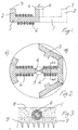
- Fig. 1 a core part which has a radial part 1 connecting a rim part 2 and a central part 4. The parts are fitted together as shown on in Fig. 2, thereby forming a rim 3 and a central pole 5.
- These core parts are made of a ferrite-type material or a magnetic concrete, and each radial part 1 is surrounded by a coil (6) of insulated wire which is energised by an ELF current in the range 20 kHz to 100 kHz.
- a hexagonal rim is obtained, and at b) is given an example of a core part which when fitted with five other core parts will create a circular rim.
- the advantage of the hexagonal rim is that it permits the closest tesselation of a surface which is to be supplied with a number of induction coils.
- each coil 6 is made to contact a thermally conductive material 7. In practice, this may occur during assembly by casting the core parts into an electrically and thermally insulating material 8 after assembly, and to cast a thermally conductive material 7 on its lower side.
- the thermally conductive material may have heat dissipating fins 9 on the surface which faces downwards.
Landscapes
- Physics & Mathematics (AREA)
- Electromagnetism (AREA)
- General Induction Heating (AREA)
- Heat Treatment Of Articles (AREA)
Abstract
Description
- The invention relates to an induction heating element for the preparation of food comprising a core structure with coils.
- Known induction heating elements are based on the use of a flat "pancake" coil disposed below parallel to the cooking utensil placed on the cooktop see for example EP-A-0 158 353. In order to increase efficiency and to reduce radiation it is known to place a set of radially disposed ferrite rods immediately below the flat coil or to place the coil within a dedicated core structure with a circular elevated rim and a central pole piece. Neither of these solutions provide maximum efficiency for the heating element (or coil-and-core) as such.
- It is the purpose of the invention to improve on this situation by utilizing the coil and core materials in a better way while still providing a field distribution that functions with existing cooking vessels. This is obtained according to the invention in that the core structure consists of radially disposed core parts having at one end a pole piece of a first type which cooperates with other pole pieces of the same kind to form a rim and at the other end a pole piece of a second kind cooperating with other pole pieces of the same kind to form a central pole, each radially disposed core part being supplied with an essentially cylindrical coil. The efficiency in the utilization of the windings for generating flux in the core structure is increased which means that stray flux which occurs when a cooking vessel is misplaced or of the wrong dimension, or even unsuitable for induction heating, will reflect more clearly on the complex impedance of the coil-and-core assembly as seen from its terminals.
- In an advantageous embodiment the rim is circular. This means that the complete assembly of core with coils creates an induction heating element very similar to the dedicated core structure mentioned above. However, the efficiency is improved due to improved control over the flux lines.
- In a further advantageous embodiment the rim is hexagonal. This means that a number of assemblies may be packed very tightly in the cooktop, and that suitable controls may be used to obtain differential energization.
- In a further advantageous embodiment at least the lower part of the coils are in close heat conducting contact with cooling means. The cooling conditions for a structure of the kind according to the invention contribute to the increase of efficiency in that the windings themselves are accessible below the core structure rather than being enclosed by the core structure. This means that by encapsulating at least the lower parts of the the coils in heat conductive material it is possible to cool the assembly in a more efficient manner.
- The invention will be described in greater detail with reference to the drawing in which
- Fig. 1 shows a radially disposed core part according to the invention,
- Fig. 2 shows the arrangement of an induction heating element with hexagonal rim from above, and
- Fig. 3 shows the same in a section along line A-A.
-
- In Fig. 1 is shown a core part which has a radial part 1 connecting a
rim part 2 and acentral part 4. The parts are fitted together as shown on in Fig. 2, thereby forming arim 3 and a central pole 5. These core parts are made of a ferrite-type material or a magnetic concrete, and each radial part 1 is surrounded by a coil (6) of insulated wire which is energised by an ELF current in the range 20 kHz to 100 kHz. - At a) is indicated how a hexagonal rim is obtained, and at b) is given an example of a core part which when fitted with five other core parts will create a circular rim. The advantage of the hexagonal rim is that it permits the closest tesselation of a surface which is to be supplied with a number of induction coils.
- In use, the current through the
coils 6 will generate heat, and in order to dissipate this, eachcoil 6 is made to contact a thermallyconductive material 7. In practice, this may occur during assembly by casting the core parts into an electrically and thermally insulating material 8 after assembly, and to cast a thermallyconductive material 7 on its lower side. The thermally conductive material may have heat dissipating fins 9 on the surface which faces downwards.
Claims (4)
- An induction heating element for the preparation of food comprising a core structure with coils, characterized in that the core structure consists of radially disposed core parts (1) having at one end a pole piece (2) of a first type which cooperates with other pole pieces of the same kind to form a rim (3) and at the other end a pole piece of a second kind (4) cooperating with other pole pieces of the same kind to form a central pole (5), each radially disposed core part (1) being supplied with an essentially cylindrical coil (6).
- An induction heating element according to claim 1, characterized in that the rim (3) is circular.
- An induction heating element according to claim 1, characterized in that the rim (3) is hexagonal.
- An induction heating element according to any of the above claims, characterized in that at least the lower part of the coils (6) are in close heat conducting contact with cooling means.
Applications Claiming Priority (3)
| Application Number | Priority Date | Filing Date | Title |
|---|---|---|---|
| DK27797 | 1997-03-13 | ||
| DK27797 | 1997-03-13 | ||
| PCT/DK1998/000097 WO1998041062A2 (en) | 1997-03-13 | 1998-03-13 | Flux guiding and cooling arrangements for induction heating units |
Publications (2)
| Publication Number | Publication Date |
|---|---|
| EP0966867A2 EP0966867A2 (en) | 1999-12-29 |
| EP0966867B1 true EP0966867B1 (en) | 2005-01-05 |
Family
ID=8091743
Family Applications (1)
| Application Number | Title | Priority Date | Filing Date |
|---|---|---|---|
| EP98907904A Expired - Lifetime EP0966867B1 (en) | 1997-03-13 | 1998-03-13 | Flux guiding and cooling arrangements for induction heating units |
Country Status (10)
| Country | Link |
|---|---|
| US (1) | US6121591A (en) |
| EP (1) | EP0966867B1 (en) |
| JP (1) | JP2001514790A (en) |
| KR (1) | KR20000076137A (en) |
| AT (1) | ATE286647T1 (en) |
| AU (1) | AU746801B2 (en) |
| CA (1) | CA2283427A1 (en) |
| DE (1) | DE69828491T2 (en) |
| NZ (1) | NZ337932A (en) |
| WO (1) | WO1998041062A2 (en) |
Families Citing this family (9)
| Publication number | Priority date | Publication date | Assignee | Title |
|---|---|---|---|---|
| DE10006863C2 (en) * | 2000-02-04 | 2002-08-29 | Aeg Hausgeraete Gmbh | cooking means |
| DE10011773B4 (en) * | 2000-03-10 | 2004-10-21 | AEG Hausgeräte GmbH | Induction cooking device with shielding device |
| US20050092738A1 (en) * | 2003-10-31 | 2005-05-05 | Ring Edmund J. | Inductive heating device including an inductive coupling assembly |
| US7323666B2 (en) | 2003-12-08 | 2008-01-29 | Saint-Gobain Performance Plastics Corporation | Inductively heatable components |
| ES2303431B1 (en) * | 2006-02-21 | 2009-04-01 | Bsh Electrodomesticos España, S.A. | INDUCTION KITCHEN PLATE AND PROCEDURE FOR THE MANUFACTURE OF AN INDUCTION KITCHEN PLATE. |
| US20090084777A1 (en) * | 2006-10-02 | 2009-04-02 | Oh Doo Yong | Cooking device having an induction heating element |
| GB2458457B (en) * | 2008-03-17 | 2010-10-20 | Dynamic Dinosaurs Bv | Transformer |
| US9095005B2 (en) | 2008-05-20 | 2015-07-28 | Kenyon International, Inc. | Induction cook-top apparatus |
| GB2596549B (en) * | 2020-06-30 | 2022-10-19 | Dyson Technology Ltd | A foodstuff preparation device |
Citations (2)
| Publication number | Priority date | Publication date | Assignee | Title |
|---|---|---|---|---|
| US3980858A (en) * | 1973-08-22 | 1976-09-14 | Mitsubishi Denki Kabushiki Kaisha | Exciter for induction heating apparatus |
| EP0158353A2 (en) * | 1984-04-11 | 1985-10-16 | TDK Corporation | A cold electric burner |
Family Cites Families (4)
| Publication number | Priority date | Publication date | Assignee | Title |
|---|---|---|---|---|
| US3663782A (en) * | 1971-06-10 | 1972-05-16 | United States Steel Corp | Laminated iron core induction corner-heating unit |
| FR2608348B1 (en) * | 1986-12-10 | 1993-11-12 | Electricite De France | ELECTRICAL INDUCTION COOKING APPARATUS WITH REDUCED HARMONIC EMISSION |
| US5053593A (en) * | 1989-01-23 | 1991-10-01 | Nikko Corporation Ltd. | Low-frequency electromagnetic induction heater |
| FR2657486B1 (en) * | 1990-01-24 | 1992-04-03 | Bonnet Sa | ELECTROMAGNETIC INDUCTION COOKING APPARATUS. |
-
1998
- 1998-03-13 KR KR1019997008227A patent/KR20000076137A/en active IP Right Grant
- 1998-03-13 CA CA002283427A patent/CA2283427A1/en not_active Abandoned
- 1998-03-13 AT AT98907904T patent/ATE286647T1/en not_active IP Right Cessation
- 1998-03-13 EP EP98907904A patent/EP0966867B1/en not_active Expired - Lifetime
- 1998-03-13 DE DE69828491T patent/DE69828491T2/en not_active Expired - Fee Related
- 1998-03-13 WO PCT/DK1998/000097 patent/WO1998041062A2/en active IP Right Grant
- 1998-03-13 JP JP53910798A patent/JP2001514790A/en active Pending
- 1998-03-13 US US09/380,350 patent/US6121591A/en not_active Expired - Fee Related
- 1998-03-13 AU AU66108/98A patent/AU746801B2/en not_active Ceased
- 1998-03-13 NZ NZ337932A patent/NZ337932A/en unknown
Patent Citations (2)
| Publication number | Priority date | Publication date | Assignee | Title |
|---|---|---|---|---|
| US3980858A (en) * | 1973-08-22 | 1976-09-14 | Mitsubishi Denki Kabushiki Kaisha | Exciter for induction heating apparatus |
| EP0158353A2 (en) * | 1984-04-11 | 1985-10-16 | TDK Corporation | A cold electric burner |
Also Published As
| Publication number | Publication date |
|---|---|
| EP0966867A2 (en) | 1999-12-29 |
| US6121591A (en) | 2000-09-19 |
| AU6610898A (en) | 1998-09-29 |
| CA2283427A1 (en) | 1998-09-17 |
| AU746801B2 (en) | 2002-05-02 |
| NZ337932A (en) | 2001-06-29 |
| WO1998041062A3 (en) | 1998-11-26 |
| JP2001514790A (en) | 2001-09-11 |
| KR20000076137A (en) | 2000-12-26 |
| DE69828491T2 (en) | 2006-01-05 |
| DE69828491D1 (en) | 2005-02-10 |
| ATE286647T1 (en) | 2005-01-15 |
| WO1998041062A2 (en) | 1998-09-17 |
Similar Documents
| Publication | Publication Date | Title |
|---|---|---|
| US5686006A (en) | Induction cooker with coil support having spiral-shaped housing for spiral coil | |
| US6498325B1 (en) | Modular induction heated cooking hob having reduced radiation and a method of making the same | |
| JPH1054565A (en) | Highly efficient induction cooking range | |
| EP0966867B1 (en) | Flux guiding and cooling arrangements for induction heating units | |
| US20090020526A1 (en) | Induction device comprising multiple individual coils for induction heating plates | |
| US6661327B1 (en) | Electromagnetic inductor and transformer device and method making the same | |
| AU689535B2 (en) | Induction heating element | |
| US4812608A (en) | Oven for thermo-magnetic treatment of toroidal coils of amorphous ferro-magnetic ribbon material | |
| FI92008C (en) | Induction hob or hob | |
| WO2017093168A1 (en) | An inductive coil unit | |
| JP4318362B2 (en) | Induction heating device | |
| JPS6144731A (en) | Magnetic yoke inductor for use of glass fiber manufacture apparatus | |
| JP2002043044A (en) | Heating coil for induction heating device | |
| US20230180355A1 (en) | Combined inductor shielding system | |
| JPH1126143A (en) | Electromagnetic induction heating coil | |
| JP2626034B2 (en) | Induction heating device | |
| JP3636484B2 (en) | Electromagnetic cooker | |
| KR890000292Y1 (en) | Heating coil of induction heating device | |
| JP3675015B2 (en) | Induction heating device manufacturing method | |
| JPH07335447A (en) | Transformer | |
| JPH0732065B2 (en) | Induction heating cooker | |
| JP3869892B2 (en) | Electromagnetic induction heating coil | |
| JPH1140338A (en) | Induction heater | |
| KR20230091103A (en) | Compact and lightweight electromagnetic shielding for high-power inductors | |
| US3740516A (en) | Radio frequency transformer for induction heating installation |
Legal Events
| Date | Code | Title | Description |
|---|---|---|---|
| PUAI | Public reference made under article 153(3) epc to a published international application that has entered the european phase |
Free format text: ORIGINAL CODE: 0009012 |
|
| 17P | Request for examination filed |
Effective date: 19991002 |
|
| AK | Designated contracting states |
Kind code of ref document: A2 Designated state(s): AT BE CH DE DK ES FI FR GB IE IT LI NL SE |
|
| GRAP | Despatch of communication of intention to grant a patent |
Free format text: ORIGINAL CODE: EPIDOSNIGR1 |
|
| GRAA | (expected) grant |
Free format text: ORIGINAL CODE: 0009210 |
|
| GRAS | Grant fee paid |
Free format text: ORIGINAL CODE: EPIDOSNIGR3 |
|
| AK | Designated contracting states |
Kind code of ref document: B1 Designated state(s): AT BE CH DE DK ES FI FR GB IE IT LI NL SE |
|
| PG25 | Lapsed in a contracting state [announced via postgrant information from national office to epo] |
Ref country code: NL Free format text: LAPSE BECAUSE OF FAILURE TO SUBMIT A TRANSLATION OF THE DESCRIPTION OR TO PAY THE FEE WITHIN THE PRESCRIBED TIME-LIMIT Effective date: 20050105 Ref country code: LI Free format text: LAPSE BECAUSE OF FAILURE TO SUBMIT A TRANSLATION OF THE DESCRIPTION OR TO PAY THE FEE WITHIN THE PRESCRIBED TIME-LIMIT Effective date: 20050105 Ref country code: IT Free format text: LAPSE BECAUSE OF FAILURE TO SUBMIT A TRANSLATION OF THE DESCRIPTION OR TO PAY THE FEE WITHIN THE PRESCRIBED TIME-LIMIT;WARNING: LAPSES OF ITALIAN PATENTS WITH EFFECTIVE DATE BEFORE 2007 MAY HAVE OCCURRED AT ANY TIME BEFORE 2007. THE CORRECT EFFECTIVE DATE MAY BE DIFFERENT FROM THE ONE RECORDED. Effective date: 20050105 Ref country code: FI Free format text: LAPSE BECAUSE OF FAILURE TO SUBMIT A TRANSLATION OF THE DESCRIPTION OR TO PAY THE FEE WITHIN THE PRESCRIBED TIME-LIMIT Effective date: 20050105 Ref country code: CH Free format text: LAPSE BECAUSE OF FAILURE TO SUBMIT A TRANSLATION OF THE DESCRIPTION OR TO PAY THE FEE WITHIN THE PRESCRIBED TIME-LIMIT Effective date: 20050105 Ref country code: BE Free format text: LAPSE BECAUSE OF FAILURE TO SUBMIT A TRANSLATION OF THE DESCRIPTION OR TO PAY THE FEE WITHIN THE PRESCRIBED TIME-LIMIT Effective date: 20050105 Ref country code: AT Free format text: LAPSE BECAUSE OF FAILURE TO SUBMIT A TRANSLATION OF THE DESCRIPTION OR TO PAY THE FEE WITHIN THE PRESCRIBED TIME-LIMIT Effective date: 20050105 |
|
| REG | Reference to a national code |
Ref country code: GB Ref legal event code: FG4D |
|
| REG | Reference to a national code |
Ref country code: CH Ref legal event code: EP |
|
| REG | Reference to a national code |
Ref country code: IE Ref legal event code: FG4D |
|
| REF | Corresponds to: |
Ref document number: 69828491 Country of ref document: DE Date of ref document: 20050210 Kind code of ref document: P |
|
| PGFP | Annual fee paid to national office [announced via postgrant information from national office to epo] |
Ref country code: FR Payment date: 20050308 Year of fee payment: 8 |
|
| PGFP | Annual fee paid to national office [announced via postgrant information from national office to epo] |
Ref country code: DE Payment date: 20050310 Year of fee payment: 8 |
|
| PG25 | Lapsed in a contracting state [announced via postgrant information from national office to epo] |
Ref country code: IE Free format text: LAPSE BECAUSE OF NON-PAYMENT OF DUE FEES Effective date: 20050314 |
|
| PG25 | Lapsed in a contracting state [announced via postgrant information from national office to epo] |
Ref country code: SE Free format text: LAPSE BECAUSE OF FAILURE TO SUBMIT A TRANSLATION OF THE DESCRIPTION OR TO PAY THE FEE WITHIN THE PRESCRIBED TIME-LIMIT Effective date: 20050405 Ref country code: GB Free format text: LAPSE BECAUSE OF NON-PAYMENT OF DUE FEES Effective date: 20050405 Ref country code: DK Free format text: LAPSE BECAUSE OF FAILURE TO SUBMIT A TRANSLATION OF THE DESCRIPTION OR TO PAY THE FEE WITHIN THE PRESCRIBED TIME-LIMIT Effective date: 20050405 |
|
| PG25 | Lapsed in a contracting state [announced via postgrant information from national office to epo] |
Ref country code: ES Free format text: LAPSE BECAUSE OF FAILURE TO SUBMIT A TRANSLATION OF THE DESCRIPTION OR TO PAY THE FEE WITHIN THE PRESCRIBED TIME-LIMIT Effective date: 20050416 |
|
| NLV1 | Nl: lapsed or annulled due to failure to fulfill the requirements of art. 29p and 29m of the patents act | ||
| REG | Reference to a national code |
Ref country code: CH Ref legal event code: PL |
|
| PLBE | No opposition filed within time limit |
Free format text: ORIGINAL CODE: 0009261 |
|
| STAA | Information on the status of an ep patent application or granted ep patent |
Free format text: STATUS: NO OPPOSITION FILED WITHIN TIME LIMIT |
|
| ET | Fr: translation filed | ||
| 26N | No opposition filed |
Effective date: 20051006 |
|
| GBPC | Gb: european patent ceased through non-payment of renewal fee |
Effective date: 20050405 |
|
| REG | Reference to a national code |
Ref country code: IE Ref legal event code: MM4A |
|
| REG | Reference to a national code |
Ref country code: GB Ref legal event code: FG4D |
|
| PG25 | Lapsed in a contracting state [announced via postgrant information from national office to epo] |
Ref country code: DE Free format text: LAPSE BECAUSE OF NON-PAYMENT OF DUE FEES Effective date: 20061003 |
|
| REG | Reference to a national code |
Ref country code: FR Ref legal event code: ST Effective date: 20061130 |
|
| PG25 | Lapsed in a contracting state [announced via postgrant information from national office to epo] |
Ref country code: FR Free format text: LAPSE BECAUSE OF NON-PAYMENT OF DUE FEES Effective date: 20060331 |