EP0969143A2 - Method for improving the cleanability of coated belts with a needled web on the inside surface - Google Patents
Method for improving the cleanability of coated belts with a needled web on the inside surface Download PDFInfo
- Publication number
- EP0969143A2 EP0969143A2 EP99850051A EP99850051A EP0969143A2 EP 0969143 A2 EP0969143 A2 EP 0969143A2 EP 99850051 A EP99850051 A EP 99850051A EP 99850051 A EP99850051 A EP 99850051A EP 0969143 A2 EP0969143 A2 EP 0969143A2
- Authority
- EP
- European Patent Office
- Prior art keywords
- staple fiber
- reinforcing base
- fiber batt
- belt
- polymeric
- Prior art date
- Legal status (The legal status is an assumption and is not a legal conclusion. Google has not performed a legal analysis and makes no representation as to the accuracy of the status listed.)
- Granted
Links
Images

Classifications
-
- D—TEXTILES; PAPER
- D21—PAPER-MAKING; PRODUCTION OF CELLULOSE
- D21F—PAPER-MAKING MACHINES; METHODS OF PRODUCING PAPER THEREON
- D21F11/00—Processes for making continuous lengths of paper, or of cardboard, or of wet web for fibre board production, on paper-making machines
-
- D—TEXTILES; PAPER
- D21—PAPER-MAKING; PRODUCTION OF CELLULOSE
- D21F—PAPER-MAKING MACHINES; METHODS OF PRODUCING PAPER THEREON
- D21F7/00—Other details of machines for making continuous webs of paper
- D21F7/08—Felts
- D21F7/086—Substantially impermeable for transferring fibrous webs
-
- D—TEXTILES; PAPER
- D21—PAPER-MAKING; PRODUCTION OF CELLULOSE
- D21F—PAPER-MAKING MACHINES; METHODS OF PRODUCING PAPER THEREON
- D21F3/00—Press section of machines for making continuous webs of paper
- D21F3/02—Wet presses
- D21F3/04—Arrangements thereof
-
- D—TEXTILES; PAPER
- D21—PAPER-MAKING; PRODUCTION OF CELLULOSE
- D21F—PAPER-MAKING MACHINES; METHODS OF PRODUCING PAPER THEREON
- D21F7/00—Other details of machines for making continuous webs of paper
- D21F7/08—Felts
- D21F7/083—Multi-layer felts
-
- Y—GENERAL TAGGING OF NEW TECHNOLOGICAL DEVELOPMENTS; GENERAL TAGGING OF CROSS-SECTIONAL TECHNOLOGIES SPANNING OVER SEVERAL SECTIONS OF THE IPC; TECHNICAL SUBJECTS COVERED BY FORMER USPC CROSS-REFERENCE ART COLLECTIONS [XRACs] AND DIGESTS
- Y10—TECHNICAL SUBJECTS COVERED BY FORMER USPC
- Y10S—TECHNICAL SUBJECTS COVERED BY FORMER USPC CROSS-REFERENCE ART COLLECTIONS [XRACs] AND DIGESTS
- Y10S162/00—Paper making and fiber liberation
- Y10S162/90—Papermaking press felts
-
- Y—GENERAL TAGGING OF NEW TECHNOLOGICAL DEVELOPMENTS; GENERAL TAGGING OF CROSS-SECTIONAL TECHNOLOGIES SPANNING OVER SEVERAL SECTIONS OF THE IPC; TECHNICAL SUBJECTS COVERED BY FORMER USPC CROSS-REFERENCE ART COLLECTIONS [XRACs] AND DIGESTS
- Y10—TECHNICAL SUBJECTS COVERED BY FORMER USPC
- Y10T—TECHNICAL SUBJECTS COVERED BY FORMER US CLASSIFICATION
- Y10T442/00—Fabric [woven, knitted, or nonwoven textile or cloth, etc.]
- Y10T442/30—Woven fabric [i.e., woven strand or strip material]
- Y10T442/3707—Woven fabric including a nonwoven fabric layer other than paper
- Y10T442/3724—Needled
- Y10T442/3764—Coated, impregnated, or autogenously bonded
-
- Y—GENERAL TAGGING OF NEW TECHNOLOGICAL DEVELOPMENTS; GENERAL TAGGING OF CROSS-SECTIONAL TECHNOLOGIES SPANNING OVER SEVERAL SECTIONS OF THE IPC; TECHNICAL SUBJECTS COVERED BY FORMER USPC CROSS-REFERENCE ART COLLECTIONS [XRACs] AND DIGESTS
- Y10—TECHNICAL SUBJECTS COVERED BY FORMER USPC
- Y10T—TECHNICAL SUBJECTS COVERED BY FORMER US CLASSIFICATION
- Y10T442/00—Fabric [woven, knitted, or nonwoven textile or cloth, etc.]
- Y10T442/30—Woven fabric [i.e., woven strand or strip material]
- Y10T442/3707—Woven fabric including a nonwoven fabric layer other than paper
- Y10T442/3772—Hydroentangled
-
- Y—GENERAL TAGGING OF NEW TECHNOLOGICAL DEVELOPMENTS; GENERAL TAGGING OF CROSS-SECTIONAL TECHNOLOGIES SPANNING OVER SEVERAL SECTIONS OF THE IPC; TECHNICAL SUBJECTS COVERED BY FORMER USPC CROSS-REFERENCE ART COLLECTIONS [XRACs] AND DIGESTS
- Y10—TECHNICAL SUBJECTS COVERED BY FORMER USPC
- Y10T—TECHNICAL SUBJECTS COVERED BY FORMER US CLASSIFICATION
- Y10T442/00—Fabric [woven, knitted, or nonwoven textile or cloth, etc.]
- Y10T442/30—Woven fabric [i.e., woven strand or strip material]
- Y10T442/3707—Woven fabric including a nonwoven fabric layer other than paper
- Y10T442/378—Coated, impregnated, or autogenously bonded
- Y10T442/3813—Coating or impregnation contains synthetic polymeric material
-
- Y—GENERAL TAGGING OF NEW TECHNOLOGICAL DEVELOPMENTS; GENERAL TAGGING OF CROSS-SECTIONAL TECHNOLOGIES SPANNING OVER SEVERAL SECTIONS OF THE IPC; TECHNICAL SUBJECTS COVERED BY FORMER USPC CROSS-REFERENCE ART COLLECTIONS [XRACs] AND DIGESTS
- Y10—TECHNICAL SUBJECTS COVERED BY FORMER USPC
- Y10T—TECHNICAL SUBJECTS COVERED BY FORMER US CLASSIFICATION
- Y10T442/00—Fabric [woven, knitted, or nonwoven textile or cloth, etc.]
- Y10T442/60—Nonwoven fabric [i.e., nonwoven strand or fiber material]
- Y10T442/659—Including an additional nonwoven fabric
- Y10T442/666—Mechanically interengaged by needling or impingement of fluid [e.g., gas or liquid stream, etc.]
- Y10T442/667—Needled
Definitions
- the present invention relates to a polymeric-resin-coated papermaking-processing belt, such as that used to transfer a paper sheet between sections, or between elements of a given section, such as the individual presses in a press section, of the paper machine on which it is being manufactured, or to carry the sheet into other processes.
- the present invention relates to a papermaking-processing belt having a base with a polymer coating on one side and a needled web on the other side.
- Sheet transfer belts are designed both to carry a newly formed paper sheet through a portion of a paper machine, so as to eliminate open draws from the machine, and to release the sheet readily to a paper machine fabric, such as a press fabric or dryer fabric, or to another rotating element, such as a press roll or transfer roll, at some desired point in the machine.
- a paper machine fabric such as a press fabric or dryer fabric
- another rotating element such as a press roll or transfer roll, at some desired point in the machine.
- an open draw is an interval where the paper sheet passes from one component of the paper machine to another over a distance greater than the length of the cellulose fibers in the sheet without any support from a papermaker's fabric.
- a closed draw is an interval where the paper sheet passes across such a distance supported by a papermaker's fabric or belt. The elimination of open draws removes a major cause of unscheduled paper machine shut-down, the breakage of the newly formed, and consequently weak, sheet at an open draw.
- a sheet transfer belt must perform three critical functions on the paper machine: a) to remove the paper sheet from a press fabric without causing sheet instability problems; b) to cooperate with a press fabric in one or more press nips to ensure optimal dewatering and high quality for the paper sheet; and c) to transfer the paper sheet in a closed draw from one press in the press section to a sheet-receiving fabric or belt in the next press, or presses, in the press section, or to a dryer fabric in the dryer section.
- a sheet transfer belt which successfully carries out these critical functions is disclosed in commonly assigned U.S. Patent No. 5,298,124, entitled “Transfer Belt” and issued on March 29, 1994, the teachings of which are incorporated herein by reference.
- the transfer belt disclosed therein has a surface topography characterized by a pressure-responsive, recoverable degree of roughness, so that, when under compression in a press nip, the degree of roughness will decrease, thereby permitting a thin, continuous water film to be formed between the transfer belt and a paper sheet to bond the paper sheet to the transfer belt upon exit from the press nip.
- the paper sheet may be removed from the transfer belt, perhaps with the assistance of a minimal amount of vacuum or suction, to a permeable fabric, such as a dryer fabric.
- the sheet transfer belt disclosed in U.S. Patent No. 5,298,124 comprises a reinforcing base with a paper side and a back side, and has a polymer coating, which includes a balanced distribution having segments of at least one polymer, on the paper side.
- the balanced distribution takes the form of a polymeric matrix which may include both hydrophobic and hydrophilic polymer segments.
- the polymer coating may also include a particulate filler.
- the reinforcing base is designed to inhibit longitudinal and transverse deformation of the transfer belt, and may be a woven fabric, and, in addition, may be endless or seamable for closing into endless form during installation on the paper machine.
- the reinforcing base may have one or more fiber batt layers attached by needling to its back side.
- the fiber batt layer or layers which may also be referred to as a needled web, are attached to the back side of the reinforcing base to control the impregnation of the polymer coating into the reinforcing base from the paper side during the manufacturing process.
- the needled web protects the load-bearing yarns of the reinforcing base from damage by abrasion.
- the needled web tends to hold paper particles during operation on a paper machine.
- normal cleaning methods such as the use of high-pressure water sprays during machine stoppages, have proven to be ineffective in removing the paper particles.
- paper particles build up on the surface of the needled web and become matted thereinto in the form of pill-like clumps of fiber and paper. These clumps tend to stick to stretch rolls and the like, which, in turn, pull them from the surface of the needled web along with some of the underlying needled web itself, thereby exposing the load-bearing yarns of the reinforcing base.
- larger clumps adhering to the surface of the needled web may cause the polymer coating on the paper side of the transfer belt, and possibly the reinforcing base itself, to be damaged by a surface doctor blade which is permanently fixed adjacent to a stretch roll or the like and cleans the paper side of the transfer belt running therearound.
- the object of the present invention is to remedy this situation by providing a transfer belt having a needled web on its inner surface, which needled web does not have a tendency to hold paper particles and is readily cleanable by normal cleaning methods.
- the present invention is a polymeric-resin-coated papermaking-processing belt, such as a sheet transfer belt, comprising a reinforcing base in the form of an endless loop.
- the reinforcing base has a face side, which is the outside of the endless loop, and a back side, which is the inside of the endless loop.
- the face side may also be referred to as the paper side.
- the face side of the reinforcing base is coated with a polymeric resin material, while the back side of the reinforcing base has a staple fiber batt attached thereto.
- the staple fiber batt on the back side of the reinforcing base has a smooth, fused surface which is free of protruding fiber ends.
- the smooth, fused surface is readily cleaned of paper particles and other materials that tend to accumulate on the inside of the belt during operation on a paper machine.
- Figure 1 is a schematic view of a representative press arrangement which includes a transfer belt for eliminating an open draw.
- the arrows in Figure 1 indicate the directions of motion or rotation of the various elements of the illustrated press arrangement.
- a paper sheet 10 represented by a dashed line, is shown as being carried on the underside of a first press fabric 12, which previously had removed the paper sheet 10 from the surface of a forming fabric, perhaps with the assistance of a suction pick-up roll.
- first press fabric 12 Carried by the first press fabric 12, the paper sheet 10 proceeds toward the right to a first support roll 14, about which is trained and directed a second press fabric 16. Paper sheet 10, sandwiched between first press fabric 12 and second press fabric 16, proceeds from first support roll 14 onward toward the right to a first press nip 18 formed by a first press roll 20 and a second press roll 22.
- first press fabric 12 Upon exit from first press nip 18, paper sheet 10 is carried by first press fabric 12 toward a second press nip 24.
- Second press fabric 16 separated from paper sheet 10 and first press fabric 12, proceeds toward second support roll 26 and back, by means of third support roll 28 and additional support rolls not shown, to first support roll 14, where it may again participate in the dewatering of paper sheet 10.
- Second press nip 24 is formed by third press roll 30 and fourth press roll 32. Carried by first press fabric 12, the paper sheet 10 proceeds upward toward second press nip 24. A transfer belt 34 is trained about fourth press roll 32, and is directed through second press nip 24 with paper sheet 10 and first press fabric 12. In second press nip 24, the paper sheet 10 is compressed between first press fabric 12 and transfer belt 34.
- paper sheet 10 Upon exit from second press nip 24, paper sheet 10 adheres to the surface of transfer belt 34, which surface is smoother than that of first press fabric 12. Paper sheet 10, now carried by transfer belt 34, proceeds from second press nip 24 to a fourth support roll 36, about which is trained and directed a third press fabric 38. Paper sheet 10, sandwiched between transfer belt 34 and third press fabric 38, proceeds onward to a third press nip 40 formed by fourth press roll 32 and a fifth press roll 42. First press fabric 12, separated from paper sheet 10 and transfer belt 34 after exiting from second press nip 24, is directed by means of fifth support roll 44 and additional support rolls not shown, to the point where it may again receive the paper sheet 10 from a forming fabric.
- third press nip 40 Upon exit from third press nip 40, paper sheet 10 again adheres to the surface of transfer belt 34, which surface is smoother than that of third press fabric 38. Paper sheet 10, again carried by transfer belt 34, proceeds downward from third press nip 40 to a vacuum transfer roll 46. Third press fabric 38, separated from paper sheet 10 and transfer belt 34 after exiting from third press nip 40, is directed by means of sixth, seventh, eighth and ninth support rolls 48,50,52,54, and additional support rolls not shown, to fourth support roll 36, where it may again participate in the dewatering of paper sheet 10.
- Transfer belt 34 no longer carrying paper sheet 10 after vacuum transfer roll 46, proceeds therefrom downward to tenth and eleventh support rolls 60,62 and to stretch roll 64, and then upward to twelfth support roll 66 and eventually back to fourth press roll 32 and to second press nip 24, where it may again accept the paper sheet 10 from the first press fabric 12.
- Transfer belt 34 allows the paper sheet 10 to be transferred from third press fabric 38 to dryer fabric 56 without an open draw. Paper sheet 10 is supported by a carrier at all points in its passage through the representative press arrangement depicted in Figure 1, and is carried by transfer belt 34 upon exit from press nip 40 because a water film between the paper sheet 10 and the transfer belt 34 is strong enough to hold paper sheet 10 thereto.
- Adjacent to stretch roll 64 is a surface doctor blade 68 which cleans the surface of the transfer belt 34.
- wet and/or dry paper particles can migrate into the inside of the loop formed by the transfer belt and its support rolls. These particles can be carried in by water spray or air around the edges of the transfer belt. These particles, as discussed above, build up on the inside of the transfer belt 34, leading to the problems previously noted.
- a large clump of paper particles, passing around the stretch roll 64 on the inside of the transfer belt 34 can raise the transfer belt 34 toward the surface doctor blade 68, which, being in a fixed position, can then abrade or cut into the outer surface of the transfer belt 34.
- the transfer belt 34 comprises a reinforcing base 80 which may be woven from warp yarns 82 and weft yarns 84 in the duplex pattern shown.
- the reinforcing base 80 has a back side 86 and a face, or paper, side 88, which are the inside and outside, respectively, of the endless loop formed by the reinforcing base 80.
- the warp yarns 82 are oriented in the cross-machine direction of the reinforcing base 80, while the weft yarns 84 are in the machine direction thereof.
- the weft yarns 84 provide seaming loops, not shown, for joining the reinforcing base 80 into endless form.
- the reinforcing base 80 may be flat-woven, and subsequently joined into endless form with a woven seam, or provided with seaming loops for joining the reinforcing base 80 into endless form.
- the warp yarns 82 are oriented in the machine direction of the reinforcing base 80, while the weft yarns 84 are oriented in its cross-machine direction.
- the reinforcing base 80 has been described above as being woven in a duplex pattern, it should be understood that it may be woven in other weave patterns known and commonly used by those of ordinary skill in the paper machine clothing arts, and that the duplex pattern shown above should be considered to be merely an example of the many weave patterns that may be used. Further, the reinforcing base 80 may alternatively be a nonwoven structure including reinforcing yarns oriented in the machine or longitudinal direction thereof and functioning as load-bearing yarns. The reinforcing base 80 may alternatively be a knitted fabric or other textile structure.
- the back side 86 of the reinforcing base 80 has one or more layers of staple fiber batt 90 needled or otherwise attached thereto, for example, by hydroentanglement.
- the staple fiber batt 90 which may also be referred to as a needled web, penetrates at least partially through the reinforcing base 80 and forms a layer 92 on the back side 86 thereof.
- the staple fiber batt 90 may comprise a plurality of staple fibers of polymeric resin material, such as polyamide or polyester staple fibers, which are commonly used for this purpose by those of ordinary skill in the paper machine clothing arts.
- the face side 88 of the reinforcing base 80 is coated with a polymer coating 94, which includes a balanced distribution having segments of at least one polymer.
- the balanced distribution takes the form of a polymeric matrix which may include both hydrophobic and hydrophilic polymer segments.
- the polymer coating 94 may also include a particulate filler 98, as disclosed in U.S. Patent No. 5,298,124, the teachings of which are incorporated herein by reference.
- the coating 94 is cured and subsequently ground to provide the transfer belt 34 with uniform thickness and with a desired surface topography.
- the staple fiber batt 90 on the back side 86 of the reinforcing base 80 has a smooth, fused surface 96.
- the smooth, fused surface 96 is formed by heating the staple fiber batt 90 to a temperature above the melting point of its constituent staple fibers.
- the reinforcing base 80 and staple fiber batt 90 are passed through a nip between a pair of rolls, which may be chilled to a temperature below the ambient. The rolls compress the reinforcing base 80 and the staple fiber batt 90.
- the heating fuses individual fibers on the surface of the staple fiber batt 90, and the subsequent compression produces a smooth, fused surface 96 with no protruding fiber ends without unduly compressing layer 92 as a whole.
- the smooth, fused surface 96 that results is easier to keep clean of paper particles and other undesirable materials that tend to accumulate during operation on a paper machine. While the fusion and subsequent compression of the surface of the staple fiber batt 90 partially seal it and reduce its permeability to water and air, sufficient permeability remains to permit the polymer coating 94, which is applied to the face side 88 of the reinforcing base 80, to penetrate into the staple fiber batt 90 and to be cured, if the smooth, fused surface 96 is produced before the polymer coating 94 is applied.
- the preferred method is a singe/compaction method.
- the apparatus 100 comprises a backing roll 102, which may be the head roll or the tail roll of a finishing table.
- the reinforcing base 80, with staple fiber batt 90 attached thereto, is mounted on the finishing table with the staple fiber batt 90 facing outward.
- the backing roll 102 for example, may have a diameter of 1.2 m.
- a compaction roll 104 which, for example, may have a diameter of 0.75 m, forms a nip 106 with the backing roll 102.
- the load of the compaction roll 104 against the backing roll 102 may be set at 35 kN/m (200 pli).
- a singeing head 108 which extends for the width of the backing roll 102.
- the singeing head 108 is propane-fired, and may be 1.25 m from nip 106 measured circumferentially around the backing roll 102 and 0.06 m (6.0 cm) from the surface of the backing roll 102.
- the arrows in Figure 3 indicate the directions of motion or rotation of the various elements of the singe/compaction apparatus 100.
- the apparatus 100 is first set to run at a speed of 25 m/min, thereby moving the reinforcing base 80 with staple fiber batt 90 attached thereto past the singeing head 108 at that speed.
- the singeing head 108 is ignited and singes the staple fiber batt 90 for three complete cycles, the first being at a speed of 25 m/min, the second being at a speed of 10 m/min, and the third being at a speed of 5 m/min.
- the singeing head 108 is extinguished and the compaction roll 104 is disengaged.
- the reinforcing base 80 with the smooth, fused fiber batt surface is then removed from apparatus 100, and is inverted for subsequent coating with polymer coating 94.
- the apparatus 120 comprises a conveyor having an endless belt 122 trained about a first roll 124 and a second roll 126.
- the conveyor carries reinforcing base 80 and staple fiber batt 90 attached thereto toward a source 128 of infrared radiation.
- the infrared radiation is of an intensity sufficient to fuse individual fibers on the surface of staple fiber batt 90.
- reinforcing base 80 and staple fiber batt 90 pass through a nip 130 formed by a first chilled calender roll 132 and a second chilled calender roll 134.
- the gap between the chilled calender rolls 132,134 is fixed at a distance which will smooth the fused surface of the staple fiber batt 90 without unduly compressing it.
- the arrows in Figure 4 indicate the directions of motion or rotation of the various elements of the apparatus 120 used for infrared heating followed by calendering.
- the smooth, fused surface 96 of the staple fiber batt 90 may be provided through the practice of alternate techniques without departing from the scope of the present invention.
- a source of ultrasonic energy could be used to similar advantage.
- the ultrasonic energy is delivered through a horn, which contacts the surface of the staple fiber batt and vibrates at a frequency higher than the human ear is able to detect.
- the vibrations of the horn cause the region of the surface with which it is in direct contact to heat in an amount sufficient to fuse its component fibers, including protruding fiber ends.
- Mechanical pressure between the horn and an underlying anvil compacts the fused fibers, thereby providing the staple fiber batt with a smooth, fused surface free of protruding fiber ends.
- staple fiber batt 90 must be on the outside of the reinforcing base 80 to be fused and compacted, that is, where the reinforcing base 80 must subsequently be inverted to place staple fiber batt 90 on the inside surface thereof, the fusion and compaction of the individual fibers on the surface of the staple fiber batt 90 must be effected before the polymer coating 94 is applied.
- inversion would not be necessary and the coating could be applied before or after the fusion/compaction operation.
Abstract
Description
- The present invention relates to a polymeric-resin-coated papermaking-processing belt, such as that used to transfer a paper sheet between sections, or between elements of a given section, such as the individual presses in a press section, of the paper machine on which it is being manufactured, or to carry the sheet into other processes. Specifically, the present invention relates to a papermaking-processing belt having a base with a polymer coating on one side and a needled web on the other side.
- Sheet transfer belts are designed both to carry a newly formed paper sheet through a portion of a paper machine, so as to eliminate open draws from the machine, and to release the sheet readily to a paper machine fabric, such as a press fabric or dryer fabric, or to another rotating element, such as a press roll or transfer roll, at some desired point in the machine. By definition, an open draw is an interval where the paper sheet passes from one component of the paper machine to another over a distance greater than the length of the cellulose fibers in the sheet without any support from a papermaker's fabric. By way of contrast, a closed draw is an interval where the paper sheet passes across such a distance supported by a papermaker's fabric or belt. The elimination of open draws removes a major cause of unscheduled paper machine shut-down, the breakage of the newly formed, and consequently weak, sheet at an open draw.
- To work successfully, a sheet transfer belt must perform three critical functions on the paper machine: a) to remove the paper sheet from a press fabric without causing sheet instability problems; b) to cooperate with a press fabric in one or more press nips to ensure optimal dewatering and high quality for the paper sheet; and c) to transfer the paper sheet in a closed draw from one press in the press section to a sheet-receiving fabric or belt in the next press, or presses, in the press section, or to a dryer fabric in the dryer section.
- A sheet transfer belt which successfully carries out these critical functions is disclosed in commonly assigned U.S. Patent No. 5,298,124, entitled "Transfer Belt" and issued on March 29, 1994, the teachings of which are incorporated herein by reference. The transfer belt disclosed therein has a surface topography characterized by a pressure-responsive, recoverable degree of roughness, so that, when under compression in a press nip, the degree of roughness will decrease, thereby permitting a thin, continuous water film to be formed between the transfer belt and a paper sheet to bond the paper sheet to the transfer belt upon exit from the press nip. When the original degree of roughness returns sometime after exit from the nip, the paper sheet may be removed from the transfer belt, perhaps with the assistance of a minimal amount of vacuum or suction, to a permeable fabric, such as a dryer fabric.
- The sheet transfer belt disclosed in U.S. Patent No. 5,298,124 comprises a reinforcing base with a paper side and a back side, and has a polymer coating, which includes a balanced distribution having segments of at least one polymer, on the paper side. The balanced distribution takes the form of a polymeric matrix which may include both hydrophobic and hydrophilic polymer segments. The polymer coating may also include a particulate filler. The reinforcing base is designed to inhibit longitudinal and transverse deformation of the transfer belt, and may be a woven fabric, and, in addition, may be endless or seamable for closing into endless form during installation on the paper machine. The reinforcing base may have one or more fiber batt layers attached by needling to its back side.
- The fiber batt layer or layers, which may also be referred to as a needled web, are attached to the back side of the reinforcing base to control the impregnation of the polymer coating into the reinforcing base from the paper side during the manufacturing process. During the life of the transfer belt on a paper machine, the needled web protects the load-bearing yarns of the reinforcing base from damage by abrasion.
- In practice, however, the needled web tends to hold paper particles during operation on a paper machine. Unfortunately, normal cleaning methods, such as the use of high-pressure water sprays during machine stoppages, have proven to be ineffective in removing the paper particles. As a consequence, paper particles build up on the surface of the needled web and become matted thereinto in the form of pill-like clumps of fiber and paper. These clumps tend to stick to stretch rolls and the like, which, in turn, pull them from the surface of the needled web along with some of the underlying needled web itself, thereby exposing the load-bearing yarns of the reinforcing base.
- Moreover, larger clumps adhering to the surface of the needled web may cause the polymer coating on the paper side of the transfer belt, and possibly the reinforcing base itself, to be damaged by a surface doctor blade which is permanently fixed adjacent to a stretch roll or the like and cleans the paper side of the transfer belt running therearound. A larger clump of fiber and paper, carried on the inside, needled-web surface of the transfer belt and passing through the fixed gap separating the surface of the roll from the surface doctor blade, raises the transfer belt toward the surface doctor blade, which, being fixed, can then abrade or cut into the belt.
- The object of the present invention is to remedy this situation by providing a transfer belt having a needled web on its inner surface, which needled web does not have a tendency to hold paper particles and is readily cleanable by normal cleaning methods.
- Accordingly, in broad terms, the present invention is a polymeric-resin-coated papermaking-processing belt, such as a sheet transfer belt, comprising a reinforcing base in the form of an endless loop. The reinforcing base has a face side, which is the outside of the endless loop, and a back side, which is the inside of the endless loop. The face side may also be referred to as the paper side.
- The face side of the reinforcing base is coated with a polymeric resin material, while the back side of the reinforcing base has a staple fiber batt attached thereto.
- In contrast to the belts of this type in the prior art, the staple fiber batt on the back side of the reinforcing base has a smooth, fused surface which is free of protruding fiber ends. The smooth, fused surface is readily cleaned of paper particles and other materials that tend to accumulate on the inside of the belt during operation on a paper machine.
- The present invention will now be disclosed in more complete detail in the discussion to follow, with appropriate reference being made to the figures identified below. Methods for manufacturing the inventive belt, including several ways for providing the staple fiber batt on the back side of the reinforcing base with the smooth, fused surface, will also be disclosed.
-
- Figure 1 is a schematic view of a representative press arrangement having a transfer belt for eliminating an open draw in a papermachine;
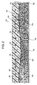
- Figure 2 is a cross-sectional view of the belt of the present invention;
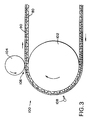
- Figure 3 is a schematic view of a singe/compaction apparatus which may be used in manufacturing the belt of the present invention; and
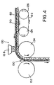
- Figure 4 is a schematic view of an alternate apparatus which may be used in manufacturing the belt of the present invention.
-
- For purposes of illustration, Figure 1 is a schematic view of a representative press arrangement which includes a transfer belt for eliminating an open draw. The arrows in Figure 1 indicate the directions of motion or rotation of the various elements of the illustrated press arrangement.
- Referring to the left side of Figure 1, a
paper sheet 10, represented by a dashed line, is shown as being carried on the underside of afirst press fabric 12, which previously had removed thepaper sheet 10 from the surface of a forming fabric, perhaps with the assistance of a suction pick-up roll. - Carried by the
first press fabric 12, thepaper sheet 10 proceeds toward the right to afirst support roll 14, about which is trained and directed asecond press fabric 16.Paper sheet 10, sandwiched betweenfirst press fabric 12 andsecond press fabric 16, proceeds fromfirst support roll 14 onward toward the right to afirst press nip 18 formed by afirst press roll 20 and asecond press roll 22. - Upon exit from
first press nip 18,paper sheet 10 is carried byfirst press fabric 12 toward asecond press nip 24.Second press fabric 16, separated frompaper sheet 10 andfirst press fabric 12, proceeds towardsecond support roll 26 and back, by means ofthird support roll 28 and additional support rolls not shown, tofirst support roll 14, where it may again participate in the dewatering ofpaper sheet 10. - Second press nip 24 is formed by
third press roll 30 andfourth press roll 32. Carried byfirst press fabric 12, thepaper sheet 10 proceeds upward towardsecond press nip 24. Atransfer belt 34 is trained aboutfourth press roll 32, and is directed throughsecond press nip 24 withpaper sheet 10 andfirst press fabric 12. Insecond press nip 24, thepaper sheet 10 is compressed betweenfirst press fabric 12 andtransfer belt 34. - Upon exit from
second press nip 24,paper sheet 10 adheres to the surface oftransfer belt 34, which surface is smoother than that offirst press fabric 12.Paper sheet 10, now carried bytransfer belt 34, proceeds fromsecond press nip 24 to afourth support roll 36, about which is trained and directed athird press fabric 38.Paper sheet 10, sandwiched betweentransfer belt 34 andthird press fabric 38, proceeds onward to athird press nip 40 formed byfourth press roll 32 and afifth press roll 42.First press fabric 12, separated frompaper sheet 10 andtransfer belt 34 after exiting fromsecond press nip 24, is directed by means offifth support roll 44 and additional support rolls not shown, to the point where it may again receive thepaper sheet 10 from a forming fabric. - Upon exit from
third press nip 40,paper sheet 10 again adheres to the surface oftransfer belt 34, which surface is smoother than that ofthird press fabric 38.Paper sheet 10, again carried bytransfer belt 34, proceeds downward fromthird press nip 40 to avacuum transfer roll 46.Third press fabric 38, separated frompaper sheet 10 andtransfer belt 34 after exiting fromthird press nip 40, is directed by means of sixth, seventh, eighth andninth support rolls fourth support roll 36, where it may again participate in the dewatering ofpaper sheet 10. - Suction from
vacuum transfer roll 46 throughdryer fabric 56 removespaper sheet 10 fromtransfer belt 34 and places it on the surface ofdryer fabric 56, which carries it toward thefirst dryer cylinder 58 of the dryer section. -
Transfer belt 34, no longer carryingpaper sheet 10 aftervacuum transfer roll 46, proceeds therefrom downward to tenth andeleventh support rolls roll 64, and then upward totwelfth support roll 66 and eventually back tofourth press roll 32 and tosecond press nip 24, where it may again accept thepaper sheet 10 from thefirst press fabric 12. -
Transfer belt 34 allows thepaper sheet 10 to be transferred fromthird press fabric 38 todryer fabric 56 without an open draw.Paper sheet 10 is supported by a carrier at all points in its passage through the representative press arrangement depicted in Figure 1, and is carried bytransfer belt 34 upon exit frompress nip 40 because a water film between thepaper sheet 10 and thetransfer belt 34 is strong enough to holdpaper sheet 10 thereto. - Adjacent to stretch
roll 64 is asurface doctor blade 68 which cleans the surface of thetransfer belt 34. During the operation of the paper machine, wet and/or dry paper particles can migrate into the inside of the loop formed by the transfer belt and its support rolls. These particles can be carried in by water spray or air around the edges of the transfer belt. These particles, as discussed above, build up on the inside of thetransfer belt 34, leading to the problems previously noted. In particular, a large clump of paper particles, passing around thestretch roll 64 on the inside of thetransfer belt 34, can raise thetransfer belt 34 toward thesurface doctor blade 68, which, being in a fixed position, can then abrade or cut into the outer surface of thetransfer belt 34. - A cross-sectional view of the
transfer belt 34 of the present invention is shown in Figure 2. Thetransfer belt 34 comprises a reinforcingbase 80 which may be woven fromwarp yarns 82 andweft yarns 84 in the duplex pattern shown. The reinforcingbase 80 has aback side 86 and a face, or paper,side 88, which are the inside and outside, respectively, of the endless loop formed by the reinforcingbase 80. Where the reinforcingbase 80 is woven endless, or woven using a modified endless weaving technique, thewarp yarns 82 are oriented in the cross-machine direction of the reinforcingbase 80, while theweft yarns 84 are in the machine direction thereof. Further, where a modified endless weaving technique is used, theweft yarns 84 provide seaming loops, not shown, for joining the reinforcingbase 80 into endless form. Alternatively, the reinforcingbase 80 may be flat-woven, and subsequently joined into endless form with a woven seam, or provided with seaming loops for joining the reinforcingbase 80 into endless form. Where the reinforcingbase 80 is flat-woven, thewarp yarns 82 are oriented in the machine direction of the reinforcingbase 80, while theweft yarns 84 are oriented in its cross-machine direction. - Although the reinforcing
base 80 has been described above as being woven in a duplex pattern, it should be understood that it may be woven in other weave patterns known and commonly used by those of ordinary skill in the paper machine clothing arts, and that the duplex pattern shown above should be considered to be merely an example of the many weave patterns that may be used. Further, the reinforcingbase 80 may alternatively be a nonwoven structure including reinforcing yarns oriented in the machine or longitudinal direction thereof and functioning as load-bearing yarns. The reinforcingbase 80 may alternatively be a knitted fabric or other textile structure. - In any event, the
back side 86 of the reinforcingbase 80 has one or more layers ofstaple fiber batt 90 needled or otherwise attached thereto, for example, by hydroentanglement. Thestaple fiber batt 90, which may also be referred to as a needled web, penetrates at least partially through the reinforcingbase 80 and forms alayer 92 on theback side 86 thereof. Thestaple fiber batt 90 may comprise a plurality of staple fibers of polymeric resin material, such as polyamide or polyester staple fibers, which are commonly used for this purpose by those of ordinary skill in the paper machine clothing arts. - The
face side 88 of the reinforcingbase 80 is coated with apolymer coating 94, which includes a balanced distribution having segments of at least one polymer. The balanced distribution takes the form of a polymeric matrix which may include both hydrophobic and hydrophilic polymer segments. Thepolymer coating 94 may also include aparticulate filler 98, as disclosed in U.S. Patent No. 5,298,124, the teachings of which are incorporated herein by reference. - The
coating 94 is cured and subsequently ground to provide thetransfer belt 34 with uniform thickness and with a desired surface topography. - The
staple fiber batt 90 on theback side 86 of the reinforcingbase 80 has a smooth, fusedsurface 96. The smooth, fusedsurface 96 is formed by heating thestaple fiber batt 90 to a temperature above the melting point of its constituent staple fibers. Immediately thereafter, the reinforcingbase 80 andstaple fiber batt 90 are passed through a nip between a pair of rolls, which may be chilled to a temperature below the ambient. The rolls compress the reinforcingbase 80 and thestaple fiber batt 90. The heating fuses individual fibers on the surface of thestaple fiber batt 90, and the subsequent compression produces a smooth, fusedsurface 96 with no protruding fiber ends without unduly compressinglayer 92 as a whole. The smooth, fusedsurface 96 that results is easier to keep clean of paper particles and other undesirable materials that tend to accumulate during operation on a paper machine. While the fusion and subsequent compression of the surface of thestaple fiber batt 90 partially seal it and reduce its permeability to water and air, sufficient permeability remains to permit thepolymer coating 94, which is applied to theface side 88 of the reinforcingbase 80, to penetrate into thestaple fiber batt 90 and to be cured, if the smooth, fusedsurface 96 is produced before thepolymer coating 94 is applied. - Several methods are available for treating the surface of the
staple fiber batt 90 in the foregoing manner. The preferred method is a singe/compaction method. - An apparatus for practicing the singe/compaction method is depicted schematically in Figure 3. The
apparatus 100 comprises abacking roll 102, which may be the head roll or the tail roll of a finishing table. The reinforcingbase 80, withstaple fiber batt 90 attached thereto, is mounted on the finishing table with thestaple fiber batt 90 facing outward. Thebacking roll 102, for example, may have a diameter of 1.2 m. - A
compaction roll 104, which, for example, may have a diameter of 0.75 m, forms a nip 106 with thebacking roll 102. The load of thecompaction roll 104 against thebacking roll 102 may be set at 35 kN/m (200 pli). - Some distance circumferentially from nip 106 on the
backing roll 102 is a singeinghead 108 which extends for the width of thebacking roll 102. The singeinghead 108 is propane-fired, and may be 1.25 m from nip 106 measured circumferentially around thebacking roll 102 and 0.06 m (6.0 cm) from the surface of thebacking roll 102. As was the case with Figure 1 above, the arrows in Figure 3 indicate the directions of motion or rotation of the various elements of the singe/compaction apparatus 100. - The
apparatus 100 is first set to run at a speed of 25 m/min, thereby moving the reinforcingbase 80 withstaple fiber batt 90 attached thereto past the singeinghead 108 at that speed. The singeinghead 108 is ignited and singes thestaple fiber batt 90 for three complete cycles, the first being at a speed of 25 m/min, the second being at a speed of 10 m/min, and the third being at a speed of 5 m/min. Shortly after each portion of thestaple fiber batt 90 is singed, it passes through the nip 106 between thebacking roll 102 and thecompaction roll 104 for compaction. At the conclusion of the three cycles, the singeinghead 108 is extinguished and thecompaction roll 104 is disengaged. The reinforcingbase 80 with the smooth, fused fiber batt surface is then removed fromapparatus 100, and is inverted for subsequent coating withpolymer coating 94. - An alternate method for treating the surface of
staple fiber batt 90 is infrared heating followed by calendering, an apparatus for which is depicted schematically in Figure 4. Theapparatus 120 comprises a conveyor having anendless belt 122 trained about afirst roll 124 and asecond roll 126. The conveyor carries reinforcingbase 80 andstaple fiber batt 90 attached thereto toward asource 128 of infrared radiation. The infrared radiation is of an intensity sufficient to fuse individual fibers on the surface ofstaple fiber batt 90. Immediately thereafter, reinforcingbase 80 andstaple fiber batt 90 pass through a nip 130 formed by a firstchilled calender roll 132 and a secondchilled calender roll 134. The gap between the chilled calender rolls 132,134 is fixed at a distance which will smooth the fused surface of thestaple fiber batt 90 without unduly compressing it. As was the case with Figures 1 and 3 above, the arrows in Figure 4 indicate the directions of motion or rotation of the various elements of theapparatus 120 used for infrared heating followed by calendering. - It should be understood that the smooth, fused
surface 96 of thestaple fiber batt 90 may be provided through the practice of alternate techniques without departing from the scope of the present invention. For example, instead of using singeinghead 108 orsource 128 of infrared radiation to fuse individual fibers on the surface ofstaple fiber batt 90, a source of ultrasonic energy could be used to similar advantage. In such a situation, the ultrasonic energy is delivered through a horn, which contacts the surface of the staple fiber batt and vibrates at a frequency higher than the human ear is able to detect. The vibrations of the horn cause the region of the surface with which it is in direct contact to heat in an amount sufficient to fuse its component fibers, including protruding fiber ends. Mechanical pressure between the horn and an underlying anvil compacts the fused fibers, thereby providing the staple fiber batt with a smooth, fused surface free of protruding fiber ends. - Moreover, it should also be understood that, where
staple fiber batt 90 must be on the outside of the reinforcingbase 80 to be fused and compacted, that is, where the reinforcingbase 80 must subsequently be inverted to placestaple fiber batt 90 on the inside surface thereof, the fusion and compaction of the individual fibers on the surface of thestaple fiber batt 90 must be effected before thepolymer coating 94 is applied. However, where the configuration of the apparatus would permit thestaple fiber batt 90 to be treated in its ultimate position on the inside of the reinforcingbase 80, inversion would not be necessary and the coating could be applied before or after the fusion/compaction operation. - While particular emphasis has been given in the preceding discussion to the application of the present invention to a transfer belt, it should be understood that the present invention may be applied to a long nip press (LNP) belt or to any other polymer-coated belt for the paper industry, such as a calender belt.
- Modifications to the above would be obvious to those of ordinary skill in the art, and would not bring the invention so modified beyond the scope of the appended claims.
Claims (23)
- A polymeric-resin-coated papermaking-processing belt comprising:a reinforcing base, said reinforcing base being in the form of an endless loop and having a face side, said face side being the outside of said endless loop, and a back side, said back side being the inside of said endless loop;a coating of a polymeric resin material on said face side of said reinforcing base; anda staple fiber batt attached to said back side of said reinforcing base, said staple fiber batt having a smooth, fused surface, said surface being free of fiber ends protruding from said staple fiber batt.
- A belt as claimed in claim 1 wherein said reinforcing base is a woven fabric.
- A belt as claimed in claim 2 wherein said woven fabric is woven endless.
- A belt as claimed in claim 2 wherein said woven fabric is woven in a modified endless weaving technique and joined into endless form with a seam.
- A belt as claimed in claim 2 wherein said woven fabric is flat-woven and joined into endless form with a woven seam.
- A belt as claimed in claim 1 wherein said reinforcing base is a nonwoven fabric.
- A belt as claimed in claim 1 wherein said staple fiber batt is attached to said reinforcing base by needling.
- A belt as claimed in claim 1 wherein said staple fiber batt is attached to said reinforcing base by hydroentangling.
- A belt as claimed in claim 1 wherein said staple fiber batt comprises a plurality of staple fibers of a polymeric resin material.
- A belt as claimed in claim 9 wherein said polymeric resin material is selected from the group consisting of polyamide and polyester resins.
- A method for manufacturing a polymeric-resin-coated papermaking-processing belt comprising the steps of:providing a reinforcing base, said reinforcing base being in the form of an endless loop having a first side and a second side;attaching a staple fiber batt to one of said first and second sides of said reinforcing base;heating said staple fiber batt at a temperature sufficient to fuse individual fibers on the surface of said staple fiber batt and fiber ends protruding therefrom;compressing said staple fiber batt after said heating step to adhere said protruding fiber ends to said individual fibers on said surface of said staple fiber batt and to smooth said surface;coating the other of said first and second sides of said reinforcing base with a polymeric resin material; andcuring said polymeric resin material to produce said polymeric-resin-coated paper-processing belt.
- A method as claimed in claim 11 wherein said steps are carried out in the listed order.
- A method as claimed in claim 11 wherein said coating and curing steps are carried out before said heating and compressing steps.
- A method as claimed in claim 11 wherein said attaching step is accomplished by needling said staple fiber batt into one of said first and second sides of said reinforcing base.
- A method as claimed in claim 11 wherein said attaching step is accomplished by the hydroentanglement of said staple fiber batt into one of said first and second sides of said reinforcing base.
- A method as claimed in claim 11 wherein said heating step is performed by exposing said staple fiber batt to a singeing head.
- A method as claimed in claim 11 wherein said heating step is performed by exposing said staple fiber batt to infrared radiation.
- A method as claimed in claim 11 wherein said heating step is performed by exposing said staple fiber batt to a source of ultrasonic energy and said compressing step is performed by pressing said staple fiber batt and reinforcing base with said source against an underlying anvil.
- A method as claimed in claim 11 wherein said compressing step is performed by passing said staple fiber batt and reinforcing base through a nip formed by a backing roll and a compaction roll.
- A method as claimed in claim 11 wherein said compressing step is performed by passing said staple fiber batt and reinforcing base through a nip formed by a pair of calender rolls.
- A method as claimed in claim 20 wherein said nip is a gap of fixed width.
- A method as claimed in claim 20 wherein said calender rolls are chilled to a temperature below the ambient temperature.
- A method as claimed in claim 11 further comprising the step of grinding said polymeric resin material subsequent to said curing step to make said polymeric-resin-coated paper-processing belt uniformly thick and to impart desired surface characteristics thereto.
Applications Claiming Priority (2)
| Application Number | Priority Date | Filing Date | Title |
|---|---|---|---|
| US106656 | 1998-06-29 | ||
| US09/106,656 US6036819A (en) | 1998-06-29 | 1998-06-29 | Method for improving the cleanability of coated belts with a needled web on the inside surface |
Publications (3)
| Publication Number | Publication Date |
|---|---|
| EP0969143A2 true EP0969143A2 (en) | 2000-01-05 |
| EP0969143A3 EP0969143A3 (en) | 2001-01-17 |
| EP0969143B1 EP0969143B1 (en) | 2003-10-29 |
Family
ID=22312574
Family Applications (1)
| Application Number | Title | Priority Date | Filing Date |
|---|---|---|---|
| EP99850051A Expired - Lifetime EP0969143B1 (en) | 1998-06-29 | 1999-03-29 | Method for improving the cleanability of coated belts with a needled web on the inside surface |
Country Status (12)
| Country | Link |
|---|---|
| US (1) | US6036819A (en) |
| EP (1) | EP0969143B1 (en) |
| JP (1) | JP4288764B2 (en) |
| KR (1) | KR100375212B1 (en) |
| CN (1) | CN1115440C (en) |
| AT (1) | ATE253139T1 (en) |
| AU (1) | AU737943B2 (en) |
| BR (1) | BR9900099A (en) |
| CA (1) | CA2255340C (en) |
| DE (1) | DE69912360T2 (en) |
| ES (1) | ES2207159T3 (en) |
| ID (1) | ID23478A (en) |
Cited By (5)
| Publication number | Priority date | Publication date | Assignee | Title |
|---|---|---|---|---|
| EP1127976A2 (en) * | 2000-02-23 | 2001-08-29 | Voith Fabrics Heidenheim GmbH & Co.KG | Papermachine belt |
| US6752908B2 (en) | 2001-06-01 | 2004-06-22 | Stowe Woodward, Llc | Shoe press belt with system for detecting operational parameters |
| WO2005098128A1 (en) * | 2004-04-08 | 2005-10-20 | Ems Chemie Ag | Press felt for paper machine and method and device for producing said felt |
| US7014733B2 (en) | 2002-05-14 | 2006-03-21 | Stowe Woodward L.L.C. | Belt for shoe press and shoe calender and method for forming same |
| EP1855877A2 (en) * | 2005-03-09 | 2007-11-21 | Astenjohnson, Inc. | Papermaking fabrics with contaminant resistant nanoparticle coating and method of in situ application |
Families Citing this family (13)
| Publication number | Priority date | Publication date | Assignee | Title |
|---|---|---|---|---|
| SE511736C2 (en) * | 1998-03-20 | 1999-11-15 | Nordiskafilt Ab Albany | Embossing ribbon for a paper machine |
| JP3272328B2 (en) * | 1999-07-19 | 2002-04-08 | 市川毛織株式会社 | Wet paper transport belt |
| US20030194930A1 (en) * | 2000-11-28 | 2003-10-16 | Joyce Michael J. | Flow control within a press fabric using batt fiber fusion methods |
| GB0204308D0 (en) * | 2002-02-23 | 2002-04-10 | Voith Fabrics Heidenheim Gmbh | Papermachine clothing |
| JP2004084125A (en) * | 2002-08-27 | 2004-03-18 | Ichikawa Woolen Textile Co Ltd | Belt for paper machine |
| US7514030B2 (en) * | 2002-12-30 | 2009-04-07 | Albany International Corp. | Fabric characteristics by flat calendering |
| GB0306769D0 (en) * | 2003-03-25 | 2003-04-30 | Voith Fabrics Heidenheim Gmbh | Composite press felt |
| US20040234716A1 (en) * | 2003-05-21 | 2004-11-25 | Madden Michael D. | Method for forming endless belt |
| ZA200607840B (en) | 2004-03-16 | 2008-05-28 | Albany Int Corp | Polyurethane coated belts and roll coverings comprising nanofillers |
| US7455752B2 (en) * | 2004-07-22 | 2008-11-25 | Albany International Corp. | Semi-permeable fabrics for transfer belt and press fabric applications |
| DE102007055902A1 (en) * | 2007-12-21 | 2009-06-25 | Voith Patent Gmbh | Tape for a machine for the production of web material |
| JP5090566B1 (en) | 2011-10-12 | 2012-12-05 | イチカワ株式会社 | Wet paper transport belt |
| EP3414383B1 (en) * | 2016-02-08 | 2019-08-28 | Lafer S.p.A. | Compacting machine for fabrics and corresponding compacting method |
Citations (1)
| Publication number | Priority date | Publication date | Assignee | Title |
|---|---|---|---|---|
| US5298124A (en) | 1992-06-11 | 1994-03-29 | Albany International Corp. | Transfer belt in a press nip closed draw transfer |
Family Cites Families (2)
| Publication number | Priority date | Publication date | Assignee | Title |
|---|---|---|---|---|
| CA1223764A (en) * | 1983-10-19 | 1987-07-07 | August Murka, Jr. | Papermaker's felt |
| NZ272169A (en) * | 1994-06-09 | 1997-06-24 | Albany Int Corp | Transfer belt for papermaking machine: seam construction: pintles passed through seaming loops |
-
1998
- 1998-06-29 US US09/106,656 patent/US6036819A/en not_active Expired - Lifetime
- 1998-12-10 CA CA002255340A patent/CA2255340C/en not_active Expired - Fee Related
- 1998-12-23 AU AU98158/98A patent/AU737943B2/en not_active Ceased
-
1999
- 1999-01-07 CN CN99101009A patent/CN1115440C/en not_active Expired - Fee Related
- 1999-01-14 BR BR9900099-7A patent/BR9900099A/en not_active Application Discontinuation
- 1999-03-02 KR KR10-1999-0006722A patent/KR100375212B1/en not_active IP Right Cessation
- 1999-03-29 DE DE69912360T patent/DE69912360T2/en not_active Expired - Lifetime
- 1999-03-29 EP EP99850051A patent/EP0969143B1/en not_active Expired - Lifetime
- 1999-03-29 AT AT99850051T patent/ATE253139T1/en active
- 1999-03-29 ES ES99850051T patent/ES2207159T3/en not_active Expired - Lifetime
- 1999-06-11 ID IDP990565D patent/ID23478A/en unknown
- 1999-06-29 JP JP18333699A patent/JP4288764B2/en not_active Expired - Fee Related
Patent Citations (1)
| Publication number | Priority date | Publication date | Assignee | Title |
|---|---|---|---|---|
| US5298124A (en) | 1992-06-11 | 1994-03-29 | Albany International Corp. | Transfer belt in a press nip closed draw transfer |
Cited By (11)
| Publication number | Priority date | Publication date | Assignee | Title |
|---|---|---|---|---|
| EP1127976A2 (en) * | 2000-02-23 | 2001-08-29 | Voith Fabrics Heidenheim GmbH & Co.KG | Papermachine belt |
| EP1127976A3 (en) * | 2000-02-23 | 2002-07-03 | Voith Fabrics Heidenheim GmbH & Co.KG | Papermachine belt |
| US6752908B2 (en) | 2001-06-01 | 2004-06-22 | Stowe Woodward, Llc | Shoe press belt with system for detecting operational parameters |
| US7014733B2 (en) | 2002-05-14 | 2006-03-21 | Stowe Woodward L.L.C. | Belt for shoe press and shoe calender and method for forming same |
| WO2005098128A1 (en) * | 2004-04-08 | 2005-10-20 | Ems Chemie Ag | Press felt for paper machine and method and device for producing said felt |
| US8591793B2 (en) | 2004-04-08 | 2013-11-26 | Ems-Chemie Ag | Press felt for paper machine and method and device for producing said felt |
| EP1855877A2 (en) * | 2005-03-09 | 2007-11-21 | Astenjohnson, Inc. | Papermaking fabrics with contaminant resistant nanoparticle coating and method of in situ application |
| EP1855877A4 (en) * | 2005-03-09 | 2009-12-23 | Astenjohnson Inc | Papermaking fabrics with contaminant resistant nanoparticle coating and method of in situ application |
| US7811627B2 (en) | 2005-03-09 | 2010-10-12 | Astenjohnson, Inc. | Papermaking fabrics with contaminant resistant nanoparticle coating and method of in situ application |
| US9562319B2 (en) | 2005-03-09 | 2017-02-07 | Astenjohnson, Inc. | Papermaking fabrics with contaminant resistant nanoparticle coating and method of in situ application |
| US10577744B2 (en) | 2005-03-09 | 2020-03-03 | Astenjohnson, Inc. | Fabric with contaminant resistant nanoparticle coating and method of in situ application |
Also Published As
| Publication number | Publication date |
|---|---|
| AU9815898A (en) | 2000-01-13 |
| DE69912360D1 (en) | 2003-12-04 |
| EP0969143A3 (en) | 2001-01-17 |
| CA2255340C (en) | 2004-11-23 |
| JP2000027088A (en) | 2000-01-25 |
| AU737943B2 (en) | 2001-09-06 |
| CN1240856A (en) | 2000-01-12 |
| BR9900099A (en) | 2000-01-04 |
| US6036819A (en) | 2000-03-14 |
| CN1115440C (en) | 2003-07-23 |
| KR20000034801A (en) | 2000-06-26 |
| KR100375212B1 (en) | 2003-03-19 |
| EP0969143B1 (en) | 2003-10-29 |
| ID23478A (en) | 2000-04-27 |
| ES2207159T3 (en) | 2004-05-16 |
| ATE253139T1 (en) | 2003-11-15 |
| CA2255340A1 (en) | 1999-12-29 |
| JP4288764B2 (en) | 2009-07-01 |
| DE69912360T2 (en) | 2004-08-05 |
Similar Documents
| Publication | Publication Date | Title |
|---|---|---|
| EP0969143B1 (en) | Method for improving the cleanability of coated belts with a needled web on the inside surface | |
| KR100607722B1 (en) | Method of manufacturing a press fabric | |
| EP0877119B1 (en) | Belts for compliant calendering | |
| AU708601B2 (en) | Spiral base structures for long nip paper machine press belts | |
| US5601877A (en) | Method of seam closure for sheet transfer and other paper processing belts | |
| EP1054099B1 (en) | Expanded film base reinforcement for papermaker's belts | |
| NZ244196A (en) | Transfer belt for papermaking machine; paper side has variable roughness depending on nip pressure | |
| JP2010159534A (en) | Calendered industrial process fabric | |
| US5965208A (en) | Coater belt and a coating station including such a coater belt | |
| TW201425038A (en) | Industrial fabric and method of welding seam area using ultrasonic welding | |
| AU3349699A (en) | Use of a transfer belt for a soft tissue paper machine | |
| WO1991002642A1 (en) | Molded paper clothing | |
| JP3764050B2 (en) | Paper machine and method for producing flexible paper | |
| JP2005023450A (en) | Felt for papermaking | |
| US7789998B2 (en) | Press fabric seam area | |
| WO2000052263A1 (en) | Transfer fabric |
Legal Events
| Date | Code | Title | Description |
|---|---|---|---|
| PUAI | Public reference made under article 153(3) epc to a published international application that has entered the european phase |
Free format text: ORIGINAL CODE: 0009012 |
|
| AK | Designated contracting states |
Kind code of ref document: A2 Designated state(s): AT BE DE ES FI FR GB IT NL SE |
|
| AX | Request for extension of the european patent |
Free format text: AL;LT;LV;MK;RO;SI |
|
| PUAL | Search report despatched |
Free format text: ORIGINAL CODE: 0009013 |
|
| AK | Designated contracting states |
Kind code of ref document: A3 Designated state(s): AT BE CH CY DE DK ES FI FR GB GR IE IT LI LU MC NL PT SE |
|
| AX | Request for extension of the european patent |
Free format text: AL;LT;LV;MK;RO;SI |
|
| 17P | Request for examination filed |
Effective date: 20001218 |
|
| AKX | Designation fees paid |
Free format text: AT BE DE ES FI FR GB IT NL SE |
|
| GRAH | Despatch of communication of intention to grant a patent |
Free format text: ORIGINAL CODE: EPIDOS IGRA |
|
| GRAS | Grant fee paid |
Free format text: ORIGINAL CODE: EPIDOSNIGR3 |
|
| GRAA | (expected) grant |
Free format text: ORIGINAL CODE: 0009210 |
|
| AK | Designated contracting states |
Kind code of ref document: B1 Designated state(s): AT BE DE ES FI FR GB IT NL SE |
|
| REG | Reference to a national code |
Ref country code: GB Ref legal event code: FG4D |
|
| REG | Reference to a national code |
Ref country code: SE Ref legal event code: TRGR |
|
| REF | Corresponds to: |
Ref document number: 69912360 Country of ref document: DE Date of ref document: 20031204 Kind code of ref document: P |
|
| PGFP | Annual fee paid to national office [announced via postgrant information from national office to epo] |
Ref country code: BE Payment date: 20040511 Year of fee payment: 6 |
|
| REG | Reference to a national code |
Ref country code: ES Ref legal event code: FG2A Ref document number: 2207159 Country of ref document: ES Kind code of ref document: T3 |
|
| ET | Fr: translation filed | ||
| PLBE | No opposition filed within time limit |
Free format text: ORIGINAL CODE: 0009261 |
|
| STAA | Information on the status of an ep patent application or granted ep patent |
Free format text: STATUS: NO OPPOSITION FILED WITHIN TIME LIMIT |
|
| 26N | No opposition filed |
Effective date: 20040730 |
|
| PG25 | Lapsed in a contracting state [announced via postgrant information from national office to epo] |
Ref country code: BE Free format text: LAPSE BECAUSE OF NON-PAYMENT OF DUE FEES Effective date: 20050331 |
|
| BERE | Be: lapsed |
Owner name: *ALBANY INTERNATIONAL CORP. Effective date: 20050331 |
|
| PGFP | Annual fee paid to national office [announced via postgrant information from national office to epo] |
Ref country code: NL Payment date: 20060228 Year of fee payment: 8 |
|
| PGFP | Annual fee paid to national office [announced via postgrant information from national office to epo] |
Ref country code: ES Payment date: 20060327 Year of fee payment: 8 |
|
| NLV4 | Nl: lapsed or anulled due to non-payment of the annual fee |
Effective date: 20071001 |
|
| BERE | Be: lapsed |
Owner name: *ALBANY INTERNATIONAL CORP. Effective date: 20050331 |
|
| PGFP | Annual fee paid to national office [announced via postgrant information from national office to epo] |
Ref country code: IT Payment date: 20070519 Year of fee payment: 9 |
|
| PG25 | Lapsed in a contracting state [announced via postgrant information from national office to epo] |
Ref country code: NL Free format text: LAPSE BECAUSE OF NON-PAYMENT OF DUE FEES Effective date: 20071001 |
|
| PGFP | Annual fee paid to national office [announced via postgrant information from national office to epo] |
Ref country code: GB Payment date: 20080327 Year of fee payment: 10 |
|
| REG | Reference to a national code |
Ref country code: ES Ref legal event code: FD2A Effective date: 20070330 |
|
| PG25 | Lapsed in a contracting state [announced via postgrant information from national office to epo] |
Ref country code: ES Free format text: LAPSE BECAUSE OF NON-PAYMENT OF DUE FEES Effective date: 20070330 |
|
| PG25 | Lapsed in a contracting state [announced via postgrant information from national office to epo] |
Ref country code: IT Free format text: LAPSE BECAUSE OF NON-PAYMENT OF DUE FEES Effective date: 20080329 |
|
| GBPC | Gb: european patent ceased through non-payment of renewal fee |
Effective date: 20090329 |
|
| PG25 | Lapsed in a contracting state [announced via postgrant information from national office to epo] |
Ref country code: GB Free format text: LAPSE BECAUSE OF NON-PAYMENT OF DUE FEES Effective date: 20090329 |
|
| PGFP | Annual fee paid to national office [announced via postgrant information from national office to epo] |
Ref country code: FR Payment date: 20100406 Year of fee payment: 12 |
|
| REG | Reference to a national code |
Ref country code: FR Ref legal event code: ST Effective date: 20111130 |
|
| PG25 | Lapsed in a contracting state [announced via postgrant information from national office to epo] |
Ref country code: FR Free format text: LAPSE BECAUSE OF NON-PAYMENT OF DUE FEES Effective date: 20110331 |
|
| PGFP | Annual fee paid to national office [announced via postgrant information from national office to epo] |
Ref country code: FI Payment date: 20120328 Year of fee payment: 14 Ref country code: SE Payment date: 20120328 Year of fee payment: 14 |
|
| PGFP | Annual fee paid to national office [announced via postgrant information from national office to epo] |
Ref country code: DE Payment date: 20120328 Year of fee payment: 14 |
|
| PGFP | Annual fee paid to national office [announced via postgrant information from national office to epo] |
Ref country code: AT Payment date: 20120302 Year of fee payment: 14 |
|
| REG | Reference to a national code |
Ref country code: SE Ref legal event code: EUG |
|
| PG25 | Lapsed in a contracting state [announced via postgrant information from national office to epo] |
Ref country code: SE Free format text: LAPSE BECAUSE OF NON-PAYMENT OF DUE FEES Effective date: 20130330 Ref country code: FI Free format text: LAPSE BECAUSE OF NON-PAYMENT OF DUE FEES Effective date: 20130329 |
|
| REG | Reference to a national code |
Ref country code: AT Ref legal event code: MM01 Ref document number: 253139 Country of ref document: AT Kind code of ref document: T Effective date: 20130329 |
|
| REG | Reference to a national code |
Ref country code: DE Ref legal event code: R119 Ref document number: 69912360 Country of ref document: DE Effective date: 20131001 |
|
| PG25 | Lapsed in a contracting state [announced via postgrant information from national office to epo] |
Ref country code: DE Free format text: LAPSE BECAUSE OF NON-PAYMENT OF DUE FEES Effective date: 20131001 Ref country code: AT Free format text: LAPSE BECAUSE OF NON-PAYMENT OF DUE FEES Effective date: 20130329 |