EP0971636B1 - Vorrichtung zur erfassung des katheter-gewebekontaktes sowie von wechselwirkungen mit dem gewebe bei der katheterablation - Google Patents
Vorrichtung zur erfassung des katheter-gewebekontaktes sowie von wechselwirkungen mit dem gewebe bei der katheterablation Download PDFInfo
- Publication number
- EP0971636B1 EP0971636B1 EP98928114A EP98928114A EP0971636B1 EP 0971636 B1 EP0971636 B1 EP 0971636B1 EP 98928114 A EP98928114 A EP 98928114A EP 98928114 A EP98928114 A EP 98928114A EP 0971636 B1 EP0971636 B1 EP 0971636B1
- Authority
- EP
- European Patent Office
- Prior art keywords
- catheter
- ablation
- tissue
- voltage
- electrode
- Prior art date
- Legal status (The legal status is an assumption and is not a legal conclusion. Google has not performed a legal analysis and makes no representation as to the accuracy of the status listed.)
- Expired - Lifetime
Links
Images


Classifications
-
- A—HUMAN NECESSITIES
- A61—MEDICAL OR VETERINARY SCIENCE; HYGIENE
- A61B—DIAGNOSIS; SURGERY; IDENTIFICATION
- A61B18/00—Surgical instruments, devices or methods for transferring non-mechanical forms of energy to or from the body
- A61B18/04—Surgical instruments, devices or methods for transferring non-mechanical forms of energy to or from the body by heating
- A61B18/12—Surgical instruments, devices or methods for transferring non-mechanical forms of energy to or from the body by heating by passing a current through the tissue to be heated, e.g. high-frequency current
- A61B18/1206—Generators therefor
-
- A—HUMAN NECESSITIES
- A61—MEDICAL OR VETERINARY SCIENCE; HYGIENE
- A61B—DIAGNOSIS; SURGERY; IDENTIFICATION
- A61B18/00—Surgical instruments, devices or methods for transferring non-mechanical forms of energy to or from the body
- A61B18/04—Surgical instruments, devices or methods for transferring non-mechanical forms of energy to or from the body by heating
- A61B18/12—Surgical instruments, devices or methods for transferring non-mechanical forms of energy to or from the body by heating by passing a current through the tissue to be heated, e.g. high-frequency current
- A61B18/14—Probes or electrodes therefor
- A61B18/1492—Probes or electrodes therefor having a flexible, catheter-like structure, e.g. for heart ablation
-
- A—HUMAN NECESSITIES
- A61—MEDICAL OR VETERINARY SCIENCE; HYGIENE
- A61B—DIAGNOSIS; SURGERY; IDENTIFICATION
- A61B17/00—Surgical instruments, devices or methods, e.g. tourniquets
- A61B2017/00017—Electrical control of surgical instruments
- A61B2017/00022—Sensing or detecting at the treatment site
- A61B2017/00039—Electric or electromagnetic phenomena other than conductivity, e.g. capacity, inductivity, Hall effect
-
- A—HUMAN NECESSITIES
- A61—MEDICAL OR VETERINARY SCIENCE; HYGIENE
- A61B—DIAGNOSIS; SURGERY; IDENTIFICATION
- A61B17/00—Surgical instruments, devices or methods, e.g. tourniquets
- A61B2017/00017—Electrical control of surgical instruments
- A61B2017/00022—Sensing or detecting at the treatment site
- A61B2017/00084—Temperature
-
- A—HUMAN NECESSITIES
- A61—MEDICAL OR VETERINARY SCIENCE; HYGIENE
- A61B—DIAGNOSIS; SURGERY; IDENTIFICATION
- A61B18/00—Surgical instruments, devices or methods for transferring non-mechanical forms of energy to or from the body
- A61B2018/00636—Sensing and controlling the application of energy
- A61B2018/0066—Sensing and controlling the application of energy without feedback, i.e. open loop control
Definitions
- the invention relates to a device for detecting the contact of one in a vessel of a Patients, especially in the bloodstream of a patient, arranged catheter to the tissue and also a Device for detecting the Interaction of radio frequency energy with the tissue of the Patients.
- WO 96/41569 discloses a device and a method for thermal ablation, at which a probe tip and a plate with different work function can be used to one to form galvanic cell.
- the galvanic cell becomes heavily loaded by a shunt impedance to one To generate current flow, by means of which a signal ready which is the tissue temperature at the Ablation site reflects.
- the invention is therefore the object of the to avoid the above-mentioned disadvantages and to a improved detection of contact between catheter and Contribute to the tissue of the patient.
- the inventor has surprisingly found that in many cases when applying electrodes to the tissue of patients, especially in blood-soaked tissue, Tensions between the electrodes and especially during the RF ablation occur.
- the electrode of an ablation catheter produces the voltage signal shown in Fig. 1, which according to of the invention in the measuring structure shown in Fig. 2 was obtained.
- a catheter located in the bloodstream produces an initially very weak voltage signal, designated here U 0 , whereas an abrupt increase in voltage occurs when the catheter electrode contacts the tissue.
- the voltage signal obtained in this way represents, with its instantaneous value or amplitude, a measure of the quality of the catheter tissue contact and can be detected without the use of additional external currents. Consequently, no electrolytic processes will occur in the present invention, and it is to be understood that further measurements, such as the recording of ECG signals, will not be adversely affected.
- the tension is an extremely accurate measure of the Contact of the catheter electrode to the tissue, while a Impedance measurement during ablation only limited to the Closing tissue contact of the catheter, and on the other This signal occurs almost without any temporal Delay on which this is suitable for real-time measurement power.
- the height of the measured signal is very high exactly with the temperature of the tissue, in particular of the during an ablation of warming tissue, correlated.
- temperature values of the am Catheter adjacent tissue with an accuracy of +. / - 1 ° C were measurable.
- they were already simple Means, i. simple high-impedance Voltage measuring devices, accuracies of +/- 2 ° C measurable.
- the temperature was regularly linear with the measured voltage in proportion, which made it possible standardized voltage measurements the same Ablation catheter or a group of identical catheters assigned.
- the occurring voltage signal for controlling or monitoring the ablation process itself to use.
- the voltage signals during the delivery of the High frequency power detected, and falls below or exceeding the shutdown or at least the Reduction of the output of the high frequency power causes is always ensured that the high frequency power in was released into the patient's tissue, and it comes to a treatment with cooler overall Catheter electrodes and increased effect.
- the attending physician in further According to the invention design specify tissue depths, the associated with the temporal integral of the measured potentials become. It can then be the device of the invention either the entire ablation process after reaching the terminate, or can be used with catheters with multiple electrodes assigned to local sections of the Catheters within which the specified values are reached were turned off, or this lower power be supplied.
- Catheter with multiple ablation electrodes can be used the signal data of each particular electrode assigned, recorded, calculated and displayed, and it The treatment process can be local to the treatment site assigned programmable ended. This allows optimized for treatment already before the start of treatment Data can also be predefined locally, and it can an optimized in relation to the respective patient Treatment to be performed.
- the in Fig. 1 illustrated voltage signal with the Voltage measuring device 1, which is a low-pass filter. 2 was upstream, won.
- the voltage taps of the low-pass filter a and b were with Platinum electrodes of a bipolar catheter connected as it
- PCT / DE96 / 00638 has been described.
- the catheter 3 needs, however, to carry out the generally no additional means for detecting the catheter temperature, such as thermal sensors, though this is due to the Invention is not excluded.
- tapping the voltage to the Catheter electrodes a and b can also reduce the voltage between the one or more indifferent electrodes 4 and one of Electrodes a, b of the catheter 3 are detected, or the place associated with the respective catheter electrode a, b become.
- the low-pass filter 2 of the first invention Embodiment is with a storage oscilloscope of the type Hameg HM 1007 connected, which in the usual way a two-dimensional display device for temporal Representation of voltage curves represents.
- the signal shoulder 8, which is after the abrupt rise the signal edge 6 extends substantially flat, shows a temporal modulation based on the mechanical Catheter tissue contact between the catheter electrode b and the fabric 7 with respect to the indifferent electrode 4 or the electrode a may be attributed or with the Production and transport of chemical substances, which cause electrical potentials at the site of the catheter, related.
- the abrupt rise 6 and drop 9 of the signal edge shows however, the emergence and termination of a catheter / tissue contact with high security.
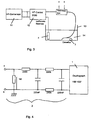
- the signal waveform for obtaining the signal waveform shown in FIG used construction is shown in Fig. 3 schematically in the form of a stationary Meß inconvenience, for standardization and calibration is usable, shown.
- An RF generator 11 is connected to the in of the PCT application cited above for the controlled delivery of RF power to the catheter 3, which has a plurality of ablation electrodes, connected and leads the electrodes of the catheter 3 pulsed High frequency power too.
- the high frequency power the catheter 3 also in time be fed continuously.
- the trough 13 can either with blood or with a suitable other Be filled with fluid in the body of the patient to simulate prevailing conditions.
- the indifferent electrode 4 and the electrodes a and b of the catheter 3 are platinum coated or consist of Platinum and are with just before its use Formalin or formaldehyde gas purified in such a way that in essentially no surface residue on the catheter or the indifferent electrode 4 remain.
- Fig. 5 compares the potential values according to the invention with temperatures which were detected at the same time at the location of the potential measurement; represents.
- the correspondence of the temperature value shown in dashed lines with the potential value 23 shown in a solid line agrees well with the model given above, since chemical potentials too are largely temperature-dependent.
- the potential decreases only to the increased value U 2 , which can be well explained by the presence of the above-discussed chemical substances.
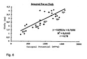
- Fig. 6 Another clear support of the explanatory model of the Potential development can be found in Fig. 6, according to which the Dependence of the depth of tissue in a patient at RF ablation produced lesions from the temporal integral the potential is represented. About one Temperature range of the ablation catheter above 20 ° C, namely from less than 55 ° C to more than 75 ° C Ablation temperature, these values are good with each other correlated. Consequently, in known Catheter features in many cases already the temporal Integral of the potential sufficient, without that in addition Temperature values should be detected to a suitable To receive information about the course of treatment.
- Such catheters could be based on thermal sensors dispense and therefore easier, cheaper and with be made smaller diameter.
- the Evaluation unit 15 can by the Evaluation unit 15 also one with the delivered power weighted or functionally linked measurement of Potential values, preferably in real time, made become.
- FIG. 2 A further embodiment according to the invention is shown in FIG. 2 represented in which the in the above cited PCT application described, pulsed generator 11 with the catheter 3 and its catheter electrodes a and b connected is.
- the catheter electrodes a and b are either the ablation electrodes themselves or in their vicinity arranged, associated with the respective Ablationselektroden Measuring electrodes, which are connected to the low-pass filter 2, which both the high frequency signal and Noise signal interference filters out.
- the downstream evaluation unit 15 includes the Voltage measuring device 1, as in the first Embodiment of the invention, a high-impedance Measuring input of at least more than 100 k ⁇ and preferably several M ⁇ input resistance to any additional current flow to the ablation process and of further measuring operations on a substantially no longer suppressible measurable value.
- a high-impedance voltage measurement a voltage measurement, when performing the ablation or the measurement of For example, ECG signals are no longer noticeable or not is more detectable.
- a storage oscilloscope with a Personal computer can be connected as a control device, the input resistance is about 1 M ⁇ , and its Input capacity is not more than 30 pF.
- the measured data obtained with the voltage measuring device 1 are recorded in the evaluation unit 15 and saved.
- the data can be either in real time or by reading from the memory of the evaluation unit 15 in two-dimensional shape shown on a display unit 21 and for comparison purposes or for the evaluation of the Treatment success are reproduced.
- the representation here can be used as instantaneous voltage signal, as a bar chart or any other, for the treating physician done ergonomically favorable manner.
- a control unit 16 assigned to the evaluation unit 15 can bring about the switching off or reduction of the power output by the HF generator 11 when the measured voltage signal falls below a predetermined value.
- Limit U g1 17 falls so as to prevent the catheter or its surroundings from being heated without producing the desired ablation.
- the limit value U g1 17 can be varied depending on the instantaneous ablation power or integrated delivered ablation power, ie, delivered ablation energy, and can thus be specified very precisely. As a result, contamination of the catheter is coagulated. Substances significantly reduced or avoided.
- the controller 16 at the beginning of the ablation process when exceeding a further limit value U g2 18 begin to integrate the output from the RF generator 11 power until the voltage signal either below the limit U g1 17 or below any other predetermined value drops.
- the size of the energy delivery into the tissue is detected, which allows the attending physician to make statements about the ablation effect.
- the treating the doctor with a visual or audible signal be given during the execution of the Treatment supported and further implementation of the Ablation, for example, based on ECG data, not with special needs.
- Control device 16 by means of an external computer or a personal computer 19 to realize.
- the invention is also not concerned with radiofrequency catheter ablation limited, but can at most other catheter ablation procedures with success Monitoring of the respective treatment success used become.
- Method for HF catheter ablation in which Tissue sections of a patient to be treated by Radiation of high frequency are ablated furthermore comprising a method as explained above for Detecting the contact between the catheter and the Patient tissue and / or the temperature of the Patient's tissue.
- Method for RF catheter ablation characterized in that the occurring voltage signal be visually and / or acoustically displayed, the visual display in the form of bar graphs, Real-time representation of the voltage signals in one two-dimensional coordinate system and / or in one Display of temporally integrated performance data.
Description
Es zeigen:
- Fig. 1
- die Signalform der erfindungsgemäßen Spannung, wie sie bei einem zeitlich begrenzten Katheterelektroden-Gewebekontakt in einem System mit indifferenter Platinelektrode sowie Platin-Katheterelektrode auftritt,
- Fig. 2
- eine schematische Darstellung zur Durchführung der Erfindung mit einem Katheter sowie einer Vorrichtung, die beispielsweise der in der PCT/DE96/00638 beschriebenen entspricht, jedoch in erfindungsgemäßer Weise weiter ausgestaltet wurden,
- Fig. 3
- einen Labor Meßaufbau zur Standardisierung bzw. Eichung sowie Meßdatengewinnung vermittels eines Schweineherzens,
- Fig. 4
- ein Tiefpaßfilter, welches bereits zusammen mit einem Oszilloskop zur Gewinnung der erfindungsgemäßen Spannungssignale verwendbar ist,
- Fig. 5
- einen Vergleich der erfindungsgemäß gewonnenen Potentialwerte mit lokal zugeordneten, an einem Ablationskatheter gewonnenen Temperaturwerten während der Katheterablation in einem lebenden Herzen,
- Fig. 6
- einen Vergleich der Werte des zeitlichen Integrals der erfindungsgemäß gewonnenen Potentialwerte mit bei der Katheterablation erreichten Läsionstiefen bei verschiedenen Temperaturen des Ablationskatheters.
Claims (13)
- Vorrichtung zur Erfassung der Wechselwirkung und/oder des Kontaktes eines in einem Gefäß eines Patienten bei der Katheterablation, insbesondere in der Blutbahn eines Patienten, angeordneten Katheters zu/mit dem Gewebe des Patienten, umfassend eine Katheterelektrode (a, b) und eine weitere Elektrode (a, b, 4) sowie eine Einrichtung (1) zur Erfassung einer Spannung zwischen der Katheterelektrode (a, b) und der weiteren Elektrode (a, b, 4) derart, dass die Spannung als Maß für den Kontakt der Katheterelektrode (a, b) zum Gewebe und zur Temperaturmessung benutzbar ist,
wobei die weitere Elektrode eine mit dem Körper des zu behandelnden Patienten in Kontakt stehende, indifferente Elektrode (4) oder eine weitere an dem Katheter (3) angebrachte Elektrode (a, b) ist. - Vorrichtung nach Anspruch 1, dadurch gekennzeichnet, daß die an die Spannungsmeßeinrichtung (1) angeschlossenen Katheterelektroden (a, b) und die indifferente Elektrode (4) aus Platin bestehen oder mit Platin beschichtet sind.
- Vorrichtung nach einem der Ansprüche von 1 oder 2, dadurch gekennzeichnet, daß die Spannungsmeßeinrichtung (1) einen Eingangswiderstand von wenigstens mehr als 100 KOhm und vorzugsweise mehrere MOhm aufweist.
- Vorrichtung nach Anspruch 3, dadurch gekennzeichnet, daß die Spannungsmeßeinrichtung (1) einen Eingangswiderstand von etwa 1 MOhm und eine Eingangskapazität von nicht mehr als 30pF aufweist.
- Vorrichtung nach einem der Ansprüche von 1 bis 4, dadurch gekennzeichnet, daß die Messung der Spannung vermittels der Spanungsmeßeinrichtung (1) während der Abgabe der Hochfrequenz-Ablationsleistung durchführbar ist.
- Vorrichtung nach einem der Ansprüche von 1 bis 5, dadurch gekennzeichnet, daß der Ablationskatheter (3) mehrere aus Platin bestehende oder mit Platin beschichtete Hochfrequenz-Ablationselektroden (a, b) umfaßt, an welchen die Spannungssignale zur Erkennung des Katheter-Gewebekontaktes und/oder der Gewebetemperatur abgegriffen werden.
- Vorrichtung nach einem der Ansprüche von 1 bis 6, ferner gekennzeichnet durch ein Tiefpaßfilter (2) zur Unterdrückung von Störungen der Hochfrequenz-Ablationssignale sowie von Brummstörungen.
- Vorrichtung nach einem der Ansprüche von 1 bis 7, ferner gekennzeichnet durch eine Einrichtung (15) zur Aufzeichnung und Speicherung der Spannungssignale, sowie vorzugsweise auch der abgegebenen Hochfrequenzablationsleistung und Energie.
- Vorrichtung nach Anspruch 8, dadurch gekennzeichnet, daß der Verlauf der Spannungssignale sowie der momentanen abgegebenen und/oder der zeitlich integrierten Ablationsleistung den jeweiligen Katheterelektroden (a, b) zugeordnet aufgezeichnet und gespeichert wird.
- Vorrichtung nach Anspruch 8 oder 9, ferner gekennzeichnet durch eine Einrichtung (16, 19) zur Anzeige und/oder Auswertung der aufgezeichneten Signale, durch welche die auftretenden Spannungssignale optisch und/oder akustisch angezeigt werden, wobei die optische Anzeige vorzugsweise in Form von Balkendiagrammen, Echtzeitdarstellung der Spannungssignale in einem zweidimensionalen Koordinatensystem und/oder durch die Anzeige von zeitlich integrierten Leistungsdaten erfolgt.
- Vorrichtung nach einem der Ansprüche von 1 bis 11, ferner gekennzeichnet durch eine Einrichtung (15, 16, 19), durch welche die Spannungssignale während der Abgabe der Hochfrequenzleistung erfaßt werden und, falls die Spannungssignale einen vorgebbar einstellbaren Grenzwert (Ug, 17) unterschreiten, die Abschaltung oder zumindest die Verminderung der Abgabe der Hochfrequenzleistung bewirkt wird.
- Vorrichtung nach einem der Ansprüche von 1 bis 11, ferner gekennzeichnet durch eine Einrichtung (16, 19), durch welche die von dem Katheter abgegebene Hochfrequenzleistung zeitlich integriert wird, so lange die Spannungssignale oberhalb eines vorgegebenen Grenzwertes (Ug, 18) liegen und durch welche die integrierte Leistung als bisher in das Gewebe abgegebene Ablationsenergie oder erreichte Wechselwirkung mit dem Gewebe oder erreichte Ablationstiefe im Gewebe berechnet und dargestellt wird.
- Vorrichtung nach Anspruch 12, ferner dadurch gekennzeichnet, daß bei Erreichen eines vorgegebenen, bisher in das Gewebe abgegebenen Ablationsenergiewertes oder erreichter Wechselwirkung mit dem Gewebe oder erreichter Ablationstiefe im Gewebe die Abgabe von Hochfrequenzleistung an die zugehörige Katheterelektrode abgeschaltet oder zumindest vermindert wird.
Applications Claiming Priority (5)
| Application Number | Priority Date | Filing Date | Title |
|---|---|---|---|
| DE19713234 | 1997-04-01 | ||
| DE19713234 | 1997-04-01 | ||
| DE19740976A DE19740976A1 (de) | 1997-04-01 | 1997-09-17 | Verfahren und Vorrichtung zur Erfassung des Katheter-Gewebekontaktes bei der HF-chirurgischen Katheterablation |
| DE19740976 | 1997-09-17 | ||
| PCT/DE1998/000932 WO1998043547A2 (de) | 1997-04-01 | 1998-04-01 | Verfahren und vorrichtung zur erfassung des katheter-gewebekontaktes sowie von wechselwirkungen mit dem gewebe bei der katheterablation |
Publications (2)
| Publication Number | Publication Date |
|---|---|
| EP0971636A2 EP0971636A2 (de) | 2000-01-19 |
| EP0971636B1 true EP0971636B1 (de) | 2005-10-26 |
Family
ID=26035367
Family Applications (1)
| Application Number | Title | Priority Date | Filing Date |
|---|---|---|---|
| EP98928114A Expired - Lifetime EP0971636B1 (de) | 1997-04-01 | 1998-04-01 | Vorrichtung zur erfassung des katheter-gewebekontaktes sowie von wechselwirkungen mit dem gewebe bei der katheterablation |
Country Status (10)
| Country | Link |
|---|---|
| US (1) | US6304776B1 (de) |
| EP (1) | EP0971636B1 (de) |
| JP (1) | JP4105238B2 (de) |
| AT (1) | ATE307536T1 (de) |
| AU (1) | AU740503B2 (de) |
| CA (1) | CA2285342C (de) |
| DE (1) | DE59813142D1 (de) |
| DK (1) | DK0971636T3 (de) |
| ES (1) | ES2249832T3 (de) |
| WO (1) | WO1998043547A2 (de) |
Families Citing this family (70)
| Publication number | Priority date | Publication date | Assignee | Title |
|---|---|---|---|---|
| US7097641B1 (en) | 1999-12-09 | 2006-08-29 | Cryocath Technologies Inc. | Catheter with cryogenic and heating ablation |
| US6569160B1 (en) | 2000-07-07 | 2003-05-27 | Biosense, Inc. | System and method for detecting electrode-tissue contact |
| US6408199B1 (en) | 2000-07-07 | 2002-06-18 | Biosense, Inc. | Bipolar mapping of intracardiac potentials with electrode having blood permeable covering |
| US6546270B1 (en) | 2000-07-07 | 2003-04-08 | Biosense, Inc. | Multi-electrode catheter, system and method |
| US7789876B2 (en) * | 2000-08-14 | 2010-09-07 | Tyco Healthcare Group, Lp | Method and apparatus for positioning a catheter relative to an anatomical junction |
| US7819870B2 (en) * | 2005-10-13 | 2010-10-26 | St. Jude Medical, Atrial Fibrillation Division, Inc. | Tissue contact and thermal assessment for brush electrodes |
| US7972298B2 (en) | 2004-03-05 | 2011-07-05 | Hansen Medical, Inc. | Robotic catheter system |
| US7824408B2 (en) | 2004-08-05 | 2010-11-02 | Tyco Healthcare Group, Lp | Methods and apparatus for coagulating and/or constricting hollow anatomical structures |
| US20070016272A1 (en) | 2004-09-27 | 2007-01-18 | Thompson Russell B | Systems and methods for treating a hollow anatomical structure |
| US7286218B2 (en) | 2004-12-19 | 2007-10-23 | Kla-Tencor Technologies Corporation | System and method for inspecting a workpiece surface using surface structure spatial frequencies |
| US7842076B2 (en) * | 2004-12-20 | 2010-11-30 | Tyco Healthcare Group, Lp | Systems and methods for treating a hollow anatomical structure |
| DE102005025946A1 (de) | 2005-01-26 | 2006-08-03 | Erbe Elektromedizin Gmbh | HF-Chirurgieeinrichtung |
| US7625372B2 (en) | 2005-02-23 | 2009-12-01 | Vnus Medical Technologies, Inc. | Methods and apparatus for coagulating and/or constricting hollow anatomical structures |
| EP1906858B1 (de) | 2005-07-01 | 2016-11-16 | Hansen Medical, Inc. | Robotergesteuertes kathetersystem |
| WO2007014063A2 (en) | 2005-07-21 | 2007-02-01 | Vnus Medical Technologies, Inc. | Systems and methods for treating a hollow anatomical structure |
| US8679109B2 (en) | 2005-10-13 | 2014-03-25 | St. Jude Medical, Atrial Fibrillation Division, Inc. | Dynamic contact assessment for electrode catheters |
| US8672936B2 (en) * | 2005-10-13 | 2014-03-18 | St. Jude Medical, Atrial Fibrillation Division, Inc. | Systems and methods for assessing tissue contact |
| US20070093697A1 (en) | 2005-10-21 | 2007-04-26 | Theranova, Llc | Method and apparatus for detection of right to left shunting in the cardiopulmonary vasculature |
| US20180311071A1 (en) | 2005-10-21 | 2018-11-01 | Daniel R. BURNETT | Method and apparatus for peritoneal oxygenation |
| EP1948057B1 (de) * | 2005-10-27 | 2012-03-14 | St. Jude Medical, Atrial Fibrillation Division, Inc. | Systeme zur beurteilung von elektrodenkontakt |
| US8190238B2 (en) | 2005-12-09 | 2012-05-29 | Hansen Medical, Inc. | Robotic catheter system and methods |
| US7879029B2 (en) | 2005-12-30 | 2011-02-01 | Biosense Webster, Inc. | System and method for selectively energizing catheter electrodes |
| US20070244371A1 (en) * | 2006-04-04 | 2007-10-18 | Nguyen Hoa D | Phlebectomy illumination device and methods |
| CN100421617C (zh) * | 2006-08-16 | 2008-10-01 | 中山市创源电子有限公司 | 一种人体阻抗测量装置及应用该装置的脂肪计 |
| US10085798B2 (en) * | 2006-12-29 | 2018-10-02 | St. Jude Medical, Atrial Fibrillation Division, Inc. | Ablation electrode with tactile sensor |
| US9579483B2 (en) | 2006-12-29 | 2017-02-28 | St. Jude Medical, Atrial Fibrillation Division, Inc. | Pressure-sensitive conductive composite contact sensor and method for contact sensing |
| US8226648B2 (en) | 2007-12-31 | 2012-07-24 | St. Jude Medical, Atrial Fibrillation Division, Inc. | Pressure-sensitive flexible polymer bipolar electrode |
| US7883508B2 (en) | 2006-12-29 | 2011-02-08 | St. Jude Medical, Atrial Fibrillation Division, Inc. | Contact-sensitive pressure-sensitive conductive composite electrode and method for ablation |
| US7955326B2 (en) * | 2006-12-29 | 2011-06-07 | St. Jude Medical, Atrial Fibrillation Division, Inc. | Pressure-sensitive conductive composite electrode and method for ablation |
| US8374673B2 (en) | 2007-01-25 | 2013-02-12 | Warsaw Orthopedic, Inc. | Integrated surgical navigational and neuromonitoring system having automated surgical assistance and control |
| US7987001B2 (en) | 2007-01-25 | 2011-07-26 | Warsaw Orthopedic, Inc. | Surgical navigational and neuromonitoring instrument |
| EP2155300A1 (de) | 2007-04-05 | 2010-02-24 | Velomedix, Inc | Automatisches therapiesystem und verfahren |
| EP2167000A1 (de) | 2007-07-09 | 2010-03-31 | Velomedix, Inc | Hypothermievorrichtungen und -verfahren |
| US8396533B2 (en) * | 2007-08-21 | 2013-03-12 | Siemens Aktiengesellschaft | Method and system for catheter detection and tracking in a fluoroscopic image sequence |
| US8211102B2 (en) * | 2007-12-21 | 2012-07-03 | St. Jude Medical, Atrial Fibrillation Division, Inc. | Contact sensing flexible conductive polymer electrode |
| US8500731B2 (en) * | 2007-12-21 | 2013-08-06 | St. Jude Medical, Atrial Fibrillation Division, Inc. | Adjustable length flexible polymer electrode catheter and method for ablation |
| US8900150B2 (en) | 2008-12-30 | 2014-12-02 | St. Jude Medical, Atrial Fibrillation Division, Inc. | Intracardiac imaging system utilizing a multipurpose catheter |
| US20100168557A1 (en) * | 2008-12-30 | 2010-07-01 | Deno D Curtis | Multi-electrode ablation sensing catheter and system |
| US8948476B2 (en) | 2010-12-20 | 2015-02-03 | St. Jude Medical, Atrial Fibrillation Division, Inc. | Determination of cardiac geometry responsive to doppler based imaging of blood flow characteristics |
| US9610118B2 (en) | 2008-12-31 | 2017-04-04 | St. Jude Medical, Atrial Fibrillation Division, Inc. | Method and apparatus for the cancellation of motion artifacts in medical interventional navigation |
| US9254123B2 (en) | 2009-04-29 | 2016-02-09 | Hansen Medical, Inc. | Flexible and steerable elongate instruments with shape control and support elements |
| US20100280328A1 (en) * | 2009-05-01 | 2010-11-04 | Tyco Healthcare Group, Lp | Methods and systems for illumination during phlebectomy procedures |
| US9616246B2 (en) | 2010-01-04 | 2017-04-11 | Covidien Lp | Apparatus and methods for treating hollow anatomical structures |
| US9237961B2 (en) * | 2010-04-23 | 2016-01-19 | Medtronic Vascular, Inc. | Stent delivery system for detecting wall apposition of the stent during deployment |
| WO2012006625A2 (en) | 2010-07-09 | 2012-01-12 | Velomedix, Inc. | Method and apparatus for pressure measurement |
| US20120191107A1 (en) | 2010-09-17 | 2012-07-26 | Tanner Neal A | Systems and methods for positioning an elongate member inside a body |
| WO2012100211A2 (en) | 2011-01-20 | 2012-07-26 | Hansen Medical, Inc. | System and method for endoluminal and transluminal therapy |
| US9138166B2 (en) | 2011-07-29 | 2015-09-22 | Hansen Medical, Inc. | Apparatus and methods for fiber integration and registration |
| US8700133B2 (en) | 2012-06-18 | 2014-04-15 | Smart Iv Llc | Apparatus and method for monitoring catheter insertion |
| US9597482B2 (en) | 2012-06-18 | 2017-03-21 | Smart Iv Llc | Apparatus and method for monitoring catheter insertion |
| DE102012220658A1 (de) * | 2012-11-13 | 2014-05-15 | Olympus Winter & Ibe Gmbh | Elektrochirurgisches Instrument für die Koagulation oder Ablation von Körpergewebe |
| US20140148673A1 (en) | 2012-11-28 | 2014-05-29 | Hansen Medical, Inc. | Method of anchoring pullwire directly articulatable region in catheter |
| US20140277334A1 (en) | 2013-03-14 | 2014-09-18 | Hansen Medical, Inc. | Active drives for robotic catheter manipulators |
| US9326822B2 (en) | 2013-03-14 | 2016-05-03 | Hansen Medical, Inc. | Active drives for robotic catheter manipulators |
| US20140276936A1 (en) | 2013-03-15 | 2014-09-18 | Hansen Medical, Inc. | Active drive mechanism for simultaneous rotation and translation |
| US9408669B2 (en) | 2013-03-15 | 2016-08-09 | Hansen Medical, Inc. | Active drive mechanism with finite range of motion |
| US10682175B2 (en) * | 2013-11-06 | 2020-06-16 | Biosense Webster (Israel) Ltd. | Using catheter position and temperature measurement to detect movement from ablation point |
| US10046140B2 (en) | 2014-04-21 | 2018-08-14 | Hansen Medical, Inc. | Devices, systems, and methods for controlling active drive systems |
| WO2017136548A1 (en) | 2016-02-04 | 2017-08-10 | Cardiac Pacemakers, Inc. | Delivery system with force sensor for leadless cardiac device |
| US10463439B2 (en) | 2016-08-26 | 2019-11-05 | Auris Health, Inc. | Steerable catheter with shaft load distributions |
| US11241559B2 (en) | 2016-08-29 | 2022-02-08 | Auris Health, Inc. | Active drive for guidewire manipulation |
| US11426126B2 (en) | 2019-05-23 | 2022-08-30 | Biosense Webster (Israel) Ltd. | Indicating electrode contact |
| US20210077180A1 (en) | 2019-09-12 | 2021-03-18 | Biosense Webster (Israel) Ltd. | Balloon Catheter with Force Sensor |
| US20220183748A1 (en) | 2020-12-16 | 2022-06-16 | Biosense Webster (Israel) Ltd. | Accurate tissue proximity |
| US11864844B2 (en) | 2020-12-22 | 2024-01-09 | Biosense Webster (Israel) Ltd. | Distal end assembly guidance |
| US20220370145A1 (en) | 2021-05-24 | 2022-11-24 | Biosense Webster (Israel) Ltd. | Gesture based selection of portion of catheter |
| US20230008606A1 (en) | 2021-07-06 | 2023-01-12 | Biosense Webster (Israel) Ltd. | Contact assessment for balloon catheter |
| US20230028867A1 (en) | 2021-07-23 | 2023-01-26 | Biosense Webster (Israel) Ltd. | Accurate tissue proximity |
| US20230157569A1 (en) | 2021-11-22 | 2023-05-25 | Biosense Webster (Israel) Ltd. | Mapping System with Real Time Electrogram Overlay |
| US20230210437A1 (en) | 2021-12-30 | 2023-07-06 | Biosense Webster (Israel) Ltd. | Intuitive Mapping System |
Family Cites Families (8)
| Publication number | Priority date | Publication date | Assignee | Title |
|---|---|---|---|---|
| DE3911416A1 (de) * | 1989-04-07 | 1990-10-11 | Delma Elektro Med App | Elektrochirurgisches hochfrequenzgeraet |
| US5419767A (en) * | 1992-01-07 | 1995-05-30 | Thapliyal And Eggers Partners | Methods and apparatus for advancing catheters through severely occluded body lumens |
| US5462545A (en) * | 1994-01-31 | 1995-10-31 | New England Medical Center Hospitals, Inc. | Catheter electrodes |
| US5562722A (en) * | 1994-03-14 | 1996-10-08 | Medical Evaluation Devices & Instruments Corp. | Multiple electrode catheter |
| US5697925A (en) * | 1995-06-09 | 1997-12-16 | Engineering & Research Associates, Inc. | Apparatus and method for thermal ablation |
| DE29519651U1 (de) | 1995-12-14 | 1996-02-01 | Muntermann Axel | Vorrichtung zur linienförmigen Radiofrequenz-Katheterablation endomyokardialen Gewebes |
| US6066139A (en) * | 1996-05-14 | 2000-05-23 | Sherwood Services Ag | Apparatus and method for sterilization and embolization |
| US5704908A (en) * | 1996-10-10 | 1998-01-06 | Genetronics, Inc. | Electroporation and iontophoresis catheter with porous balloon |
-
1998
- 1998-04-01 AT AT98928114T patent/ATE307536T1/de not_active IP Right Cessation
- 1998-04-01 ES ES98928114T patent/ES2249832T3/es not_active Expired - Lifetime
- 1998-04-01 EP EP98928114A patent/EP0971636B1/de not_active Expired - Lifetime
- 1998-04-01 DE DE59813142T patent/DE59813142D1/de not_active Expired - Lifetime
- 1998-04-01 AU AU80088/98A patent/AU740503B2/en not_active Ceased
- 1998-04-01 DK DK98928114T patent/DK0971636T3/da active
- 1998-04-01 JP JP54106898A patent/JP4105238B2/ja not_active Expired - Fee Related
- 1998-04-01 CA CA002285342A patent/CA2285342C/en not_active Expired - Fee Related
- 1998-04-01 WO PCT/DE1998/000932 patent/WO1998043547A2/de active IP Right Grant
- 1998-04-01 US US09/402,222 patent/US6304776B1/en not_active Expired - Lifetime
Also Published As
| Publication number | Publication date |
|---|---|
| ATE307536T1 (de) | 2005-11-15 |
| AU740503B2 (en) | 2001-11-08 |
| JP2001522265A (ja) | 2001-11-13 |
| WO1998043547A3 (de) | 1999-01-21 |
| US6304776B1 (en) | 2001-10-16 |
| DK0971636T3 (da) | 2006-03-20 |
| CA2285342C (en) | 2007-06-19 |
| DE59813142D1 (de) | 2005-12-01 |
| WO1998043547A2 (de) | 1998-10-08 |
| CA2285342A1 (en) | 1998-10-08 |
| AU8008898A (en) | 1998-10-22 |
| EP0971636A2 (de) | 2000-01-19 |
| ES2249832T3 (es) | 2006-04-01 |
| JP4105238B2 (ja) | 2008-06-25 |
Similar Documents
| Publication | Publication Date | Title |
|---|---|---|
| EP0971636B1 (de) | Vorrichtung zur erfassung des katheter-gewebekontaktes sowie von wechselwirkungen mit dem gewebe bei der katheterablation | |
| EP0598780B1 (de) | Hochfrequenzchirurgiegenerator zum schneiden von geweben | |
| EP0452276B1 (de) | Blutflussmessgerät | |
| EP0868884B1 (de) | Vorrichtung und Verfahren zur Katheterablation | |
| DE2817617A1 (de) | Einrichtung zum ueberwachen sowie steuern und/oder regeln der glykaemie | |
| EP0925761A1 (de) | Verfahren zum Betrieb einer Hochfrequenz-Ablationsvorrichtung und Vorrichtung für die Hochfrequenz-Gewebe-Ablation | |
| WO1993005700A1 (de) | Medizintechnisches verfahren zur messung der durchblutung eines organs und mittel dazu | |
| EP0669140A2 (de) | Insufflationsgerät | |
| WO1997021387A1 (de) | Vorrichtung zur linienförmigen hochfrequenz-katheterablation endomyokardialen gewebes | |
| DE2349624A1 (de) | Impedanz-plethysmograph | |
| DE102014219943A1 (de) | Schaltungsanordnung zur Unterdrückung von Gleichtaktstörsignalen bei der Messung von bioelektrischen Signalen | |
| DE4126607C2 (de) | Anordnung zum Schneiden von biologischem Gewebe mit Hochfrequenzstrom | |
| WO1997030630A1 (de) | Verfahren und vorrichtung zur messung des intracraniellen druckes in einem schädel eines probanden | |
| DE19740976A1 (de) | Verfahren und Vorrichtung zur Erfassung des Katheter-Gewebekontaktes bei der HF-chirurgischen Katheterablation | |
| DE1910030A1 (de) | Vorrichtung zum selbsttaetigen Ausfuehren und Auswerten von Testen der Aktivitaet von Funktionssystemen lebendiger Organismen | |
| DE102016220157A1 (de) | Hochfrequenzgenerator | |
| EP4014918B1 (de) | System zum exkavieren von zahnmaterial | |
| WO2007000247A1 (de) | Messzelle und damit durchgeführtes verfahren zur bestimmung des durch elektroporation bewirkenden aufschlussgrades biologischer zellen | |
| DE1648905B2 (de) | Verfahren und geraet zur thermischen untersuchung und beeinflussung des zustandes von medien, insbesondere von biologischem gewebe | |
| WO1998025532A1 (de) | Ablationsgerät für intrakardiale herzbehandlungen | |
| DE2431194C3 (de) | Vorrichtung zum Erfassen des Partialdruckes von Gasen | |
| DE3530456C2 (de) | ||
| DE102021110392B3 (de) | Verfahren zur Verschleissermittlung eines Werkzeugs für ein chirurgisches Hochfrequenzinstrument | |
| EP3400977B1 (de) | Online linearisierung eines optischen sensors | |
| DE3924536C2 (de) |
Legal Events
| Date | Code | Title | Description |
|---|---|---|---|
| PUAI | Public reference made under article 153(3) epc to a published international application that has entered the european phase |
Free format text: ORIGINAL CODE: 0009012 |
|
| 17P | Request for examination filed |
Effective date: 19991028 |
|
| AK | Designated contracting states |
Kind code of ref document: A2 Designated state(s): AT BE CH CY DE DK ES FI FR GB GR IE IT LI LU MC NL PT SE |
|
| AX | Request for extension of the european patent |
Free format text: AL PAYMENT 19991028;LT PAYMENT 19991028;LV PAYMENT 19991028;MK PAYMENT 19991028;RO PAYMENT 19991028;SI PAYMENT 19991028 |
|
| 17Q | First examination report despatched |
Effective date: 20030924 |
|
| GRAP | Despatch of communication of intention to grant a patent |
Free format text: ORIGINAL CODE: EPIDOSNIGR1 |
|
| RIC1 | Information provided on ipc code assigned before grant |
Ipc: 7A 61B 18/00 A |
|
| RTI1 | Title (correction) |
Free format text: DEVICE FOR DETECTING CATHETER-TISSUE CONTACT AND INTERACTION WITH TISSUE DURING CATHETER ABLATION |
|
| GRAS | Grant fee paid |
Free format text: ORIGINAL CODE: EPIDOSNIGR3 |
|
| GRAA | (expected) grant |
Free format text: ORIGINAL CODE: 0009210 |
|
| GRAL | Information related to payment of fee for publishing/printing deleted |
Free format text: ORIGINAL CODE: EPIDOSDIGR3 |
|
| GRAS | Grant fee paid |
Free format text: ORIGINAL CODE: EPIDOSNIGR3 |
|
| AK | Designated contracting states |
Kind code of ref document: B1 Designated state(s): AT BE CH CY DE DK ES FI FR GB GR IE IT LI LU MC NL PT SE |
|
| AX | Request for extension of the european patent |
Extension state: AL LT LV MK RO SI |
|
| REG | Reference to a national code |
Ref country code: GB Ref legal event code: FG4D Free format text: NOT ENGLISH |
|
| REG | Reference to a national code |
Ref country code: CH Ref legal event code: NV Representative=s name: BOVARD AG PATENTANWAELTE Ref country code: CH Ref legal event code: EP |
|
| GBT | Gb: translation of ep patent filed (gb section 77(6)(a)/1977) |
Effective date: 20051026 |
|
| REG | Reference to a national code |
Ref country code: IE Ref legal event code: FG4D Free format text: LANGUAGE OF EP DOCUMENT: GERMAN |
|
| REF | Corresponds to: |
Ref document number: 59813142 Country of ref document: DE Date of ref document: 20051201 Kind code of ref document: P |
|
| REG | Reference to a national code |
Ref country code: GR Ref legal event code: EP Ref document number: 20050403498 Country of ref document: GR |
|
| REG | Reference to a national code |
Ref country code: SE Ref legal event code: TRGR |
|
| REG | Reference to a national code |
Ref country code: DK Ref legal event code: T3 |
|
| LTIE | Lt: invalidation of european patent or patent extension |
Effective date: 20051026 |
|
| REG | Reference to a national code |
Ref country code: ES Ref legal event code: FG2A Ref document number: 2249832 Country of ref document: ES Kind code of ref document: T3 |
|
| ET | Fr: translation filed | ||
| PLBE | No opposition filed within time limit |
Free format text: ORIGINAL CODE: 0009261 |
|
| STAA | Information on the status of an ep patent application or granted ep patent |
Free format text: STATUS: NO OPPOSITION FILED WITHIN TIME LIMIT |
|
| 26N | No opposition filed |
Effective date: 20060727 |
|
| PG25 | Lapsed in a contracting state [announced via postgrant information from national office to epo] |
Ref country code: CY Free format text: LAPSE BECAUSE OF FAILURE TO SUBMIT A TRANSLATION OF THE DESCRIPTION OR TO PAY THE FEE WITHIN THE PRESCRIBED TIME-LIMIT Effective date: 20051026 |
|
| PGFP | Annual fee paid to national office [announced via postgrant information from national office to epo] |
Ref country code: PT Payment date: 20100322 Year of fee payment: 13 |
|
| PGFP | Annual fee paid to national office [announced via postgrant information from national office to epo] |
Ref country code: LU Payment date: 20100426 Year of fee payment: 13 |
|
| PGFP | Annual fee paid to national office [announced via postgrant information from national office to epo] |
Ref country code: MC Payment date: 20100421 Year of fee payment: 13 Ref country code: IE Payment date: 20100419 Year of fee payment: 13 Ref country code: FI Payment date: 20100426 Year of fee payment: 13 Ref country code: ES Payment date: 20100423 Year of fee payment: 13 Ref country code: DK Payment date: 20100426 Year of fee payment: 13 |
|
| PGFP | Annual fee paid to national office [announced via postgrant information from national office to epo] |
Ref country code: NL Payment date: 20100421 Year of fee payment: 13 Ref country code: IT Payment date: 20100427 Year of fee payment: 13 Ref country code: AT Payment date: 20100422 Year of fee payment: 13 |
|
| PGFP | Annual fee paid to national office [announced via postgrant information from national office to epo] |
Ref country code: CH Payment date: 20100426 Year of fee payment: 13 Ref country code: BE Payment date: 20100423 Year of fee payment: 13 |
|
| PGFP | Annual fee paid to national office [announced via postgrant information from national office to epo] |
Ref country code: SE Payment date: 20100423 Year of fee payment: 13 |
|
| PGFP | Annual fee paid to national office [announced via postgrant information from national office to epo] |
Ref country code: GR Payment date: 20100330 Year of fee payment: 13 |
|
| REG | Reference to a national code |
Ref country code: CH Ref legal event code: PFA Owner name: MUNTERMANN, AXEL Free format text: MUNTERMANN, AXEL#GOTENWEG 51#35578 WETZLAR (DE) -TRANSFER TO- MUNTERMANN, AXEL#GOTENWEG 51#35578 WETZLAR (DE) |
|
| REG | Reference to a national code |
Ref country code: PT Ref legal event code: MM4A Free format text: LAPSE DUE TO NON-PAYMENT OF FEES Effective date: 20111003 |
|
| BERE | Be: lapsed |
Owner name: *MUNTERMANN AXEL Effective date: 20110430 |
|
| REG | Reference to a national code |
Ref country code: NL Ref legal event code: V1 Effective date: 20111101 |
|
| REG | Reference to a national code |
Ref country code: SE Ref legal event code: EUG |
|
| PG25 | Lapsed in a contracting state [announced via postgrant information from national office to epo] |
Ref country code: MC Free format text: LAPSE BECAUSE OF NON-PAYMENT OF DUE FEES Effective date: 20110430 |
|
| REG | Reference to a national code |
Ref country code: CH Ref legal event code: PL |
|
| REG | Reference to a national code |
Ref country code: AT Ref legal event code: MM01 Ref document number: 307536 Country of ref document: AT Kind code of ref document: T Effective date: 20110401 |
|
| REG | Reference to a national code |
Ref country code: GR Ref legal event code: ML Ref document number: 20050403498 Country of ref document: GR Effective date: 20111102 |
|
| PG25 | Lapsed in a contracting state [announced via postgrant information from national office to epo] |
Ref country code: FI Free format text: LAPSE BECAUSE OF NON-PAYMENT OF DUE FEES Effective date: 20110401 Ref country code: BE Free format text: LAPSE BECAUSE OF NON-PAYMENT OF DUE FEES Effective date: 20110430 Ref country code: PT Free format text: LAPSE BECAUSE OF NON-PAYMENT OF DUE FEES Effective date: 20111003 Ref country code: NL Free format text: LAPSE BECAUSE OF NON-PAYMENT OF DUE FEES Effective date: 20111101 Ref country code: LI Free format text: LAPSE BECAUSE OF NON-PAYMENT OF DUE FEES Effective date: 20110430 Ref country code: CH Free format text: LAPSE BECAUSE OF NON-PAYMENT OF DUE FEES Effective date: 20110430 |
|
| REG | Reference to a national code |
Ref country code: IE Ref legal event code: MM4A |
|
| REG | Reference to a national code |
Ref country code: DK Ref legal event code: EBP |
|
| PG25 | Lapsed in a contracting state [announced via postgrant information from national office to epo] |
Ref country code: IT Free format text: LAPSE BECAUSE OF NON-PAYMENT OF DUE FEES Effective date: 20110401 Ref country code: AT Free format text: LAPSE BECAUSE OF NON-PAYMENT OF DUE FEES Effective date: 20110401 Ref country code: GR Free format text: LAPSE BECAUSE OF NON-PAYMENT OF DUE FEES Effective date: 20111102 |
|
| PG25 | Lapsed in a contracting state [announced via postgrant information from national office to epo] |
Ref country code: IE Free format text: LAPSE BECAUSE OF NON-PAYMENT OF DUE FEES Effective date: 20110401 |
|
| REG | Reference to a national code |
Ref country code: ES Ref legal event code: FD2A Effective date: 20120604 |
|
| PG25 | Lapsed in a contracting state [announced via postgrant information from national office to epo] |
Ref country code: DK Free format text: LAPSE BECAUSE OF NON-PAYMENT OF DUE FEES Effective date: 20110430 |
|
| PG25 | Lapsed in a contracting state [announced via postgrant information from national office to epo] |
Ref country code: ES Free format text: LAPSE BECAUSE OF NON-PAYMENT OF DUE FEES Effective date: 20110402 |
|
| PG25 | Lapsed in a contracting state [announced via postgrant information from national office to epo] |
Ref country code: SE Free format text: LAPSE BECAUSE OF NON-PAYMENT OF DUE FEES Effective date: 20110402 |
|
| PG25 | Lapsed in a contracting state [announced via postgrant information from national office to epo] |
Ref country code: LU Free format text: LAPSE BECAUSE OF NON-PAYMENT OF DUE FEES Effective date: 20110401 |
|
| PGFP | Annual fee paid to national office [announced via postgrant information from national office to epo] |
Ref country code: DE Payment date: 20130427 Year of fee payment: 16 Ref country code: GB Payment date: 20130422 Year of fee payment: 16 |
|
| PGFP | Annual fee paid to national office [announced via postgrant information from national office to epo] |
Ref country code: FR Payment date: 20130523 Year of fee payment: 16 |
|
| REG | Reference to a national code |
Ref country code: DE Ref legal event code: R119 Ref document number: 59813142 Country of ref document: DE |
|
| GBPC | Gb: european patent ceased through non-payment of renewal fee |
Effective date: 20140401 |
|
| REG | Reference to a national code |
Ref country code: FR Ref legal event code: ST Effective date: 20141231 |
|
| REG | Reference to a national code |
Ref country code: DE Ref legal event code: R119 Ref document number: 59813142 Country of ref document: DE Effective date: 20141101 |
|
| PG25 | Lapsed in a contracting state [announced via postgrant information from national office to epo] |
Ref country code: DE Free format text: LAPSE BECAUSE OF NON-PAYMENT OF DUE FEES Effective date: 20141101 Ref country code: GB Free format text: LAPSE BECAUSE OF NON-PAYMENT OF DUE FEES Effective date: 20140401 |
|
| PG25 | Lapsed in a contracting state [announced via postgrant information from national office to epo] |
Ref country code: FR Free format text: LAPSE BECAUSE OF NON-PAYMENT OF DUE FEES Effective date: 20140430 |