EP0975410B1 - A filter element having a storage device for keeping track of filter usage and a system for use therewith - Google Patents
A filter element having a storage device for keeping track of filter usage and a system for use therewith Download PDFInfo
- Publication number
- EP0975410B1 EP0975410B1 EP98910283A EP98910283A EP0975410B1 EP 0975410 B1 EP0975410 B1 EP 0975410B1 EP 98910283 A EP98910283 A EP 98910283A EP 98910283 A EP98910283 A EP 98910283A EP 0975410 B1 EP0975410 B1 EP 0975410B1
- Authority
- EP
- European Patent Office
- Prior art keywords
- filter
- respiratory system
- controller
- assembly
- air
- Prior art date
- Legal status (The legal status is an assumption and is not a legal conclusion. Google has not performed a legal analysis and makes no representation as to the accuracy of the status listed.)
- Expired - Lifetime
Links
- 238000003860 storage Methods 0.000 title claims description 19
- 210000002345 respiratory system Anatomy 0.000 claims description 29
- 206010011906 Death Diseases 0.000 claims description 10
- 238000012544 monitoring process Methods 0.000 claims description 6
- 230000000737 periodic effect Effects 0.000 claims description 3
- 230000008859 change Effects 0.000 claims description 2
- 239000003570 air Substances 0.000 description 44
- 238000001914 filtration Methods 0.000 description 20
- 230000029058 respiratory gaseous exchange Effects 0.000 description 6
- 238000013461 design Methods 0.000 description 5
- 239000007789 gas Substances 0.000 description 4
- 238000000034 method Methods 0.000 description 4
- 239000012080 ambient air Substances 0.000 description 3
- 239000003990 capacitor Substances 0.000 description 3
- 239000010408 film Substances 0.000 description 3
- 229910052751 metal Inorganic materials 0.000 description 3
- 239000002184 metal Substances 0.000 description 3
- 230000000241 respiratory effect Effects 0.000 description 3
- 230000000007 visual effect Effects 0.000 description 3
- 230000004397 blinking Effects 0.000 description 2
- 239000000919 ceramic Substances 0.000 description 2
- 238000004891 communication Methods 0.000 description 2
- 239000013078 crystal Substances 0.000 description 2
- 239000004744 fabric Substances 0.000 description 2
- 230000036541 health Effects 0.000 description 2
- 239000012535 impurity Substances 0.000 description 2
- 238000012423 maintenance Methods 0.000 description 2
- 238000004519 manufacturing process Methods 0.000 description 2
- 230000013011 mating Effects 0.000 description 2
- 238000012986 modification Methods 0.000 description 2
- 230000004048 modification Effects 0.000 description 2
- 241000894006 Bacteria Species 0.000 description 1
- 239000004698 Polyethylene Substances 0.000 description 1
- 239000004775 Tyvek Substances 0.000 description 1
- 229920000690 Tyvek Polymers 0.000 description 1
- 238000013459 approach Methods 0.000 description 1
- 244000078885 bloodborne pathogen Species 0.000 description 1
- OJIJEKBXJYRIBZ-UHFFFAOYSA-N cadmium nickel Chemical compound [Ni].[Cd] OJIJEKBXJYRIBZ-UHFFFAOYSA-N 0.000 description 1
- 239000000428 dust Substances 0.000 description 1
- 239000003517 fume Substances 0.000 description 1
- 230000006870 function Effects 0.000 description 1
- 230000005802 health problem Effects 0.000 description 1
- 239000007788 liquid Substances 0.000 description 1
- 238000005461 lubrication Methods 0.000 description 1
- 230000007246 mechanism Effects 0.000 description 1
- 238000004806 packaging method and process Methods 0.000 description 1
- -1 polyethylene Polymers 0.000 description 1
- 229920000573 polyethylene Polymers 0.000 description 1
- 230000008569 process Effects 0.000 description 1
- 230000001681 protective effect Effects 0.000 description 1
- 229910000679 solder Inorganic materials 0.000 description 1
- 229910052715 tantalum Inorganic materials 0.000 description 1
- GUVRBAGPIYLISA-UHFFFAOYSA-N tantalum atom Chemical compound [Ta] GUVRBAGPIYLISA-UHFFFAOYSA-N 0.000 description 1
- 238000012360 testing method Methods 0.000 description 1
- 239000010409 thin film Substances 0.000 description 1
Images


Classifications
-
- B—PERFORMING OPERATIONS; TRANSPORTING
- B01—PHYSICAL OR CHEMICAL PROCESSES OR APPARATUS IN GENERAL
- B01D—SEPARATION
- B01D35/00—Filtering devices having features not specifically covered by groups B01D24/00 - B01D33/00, or for applications not specifically covered by groups B01D24/00 - B01D33/00; Auxiliary devices for filtration; Filter housing constructions
- B01D35/24—Providing loose granular material to scratch the filters clean
-
- B—PERFORMING OPERATIONS; TRANSPORTING
- B01—PHYSICAL OR CHEMICAL PROCESSES OR APPARATUS IN GENERAL
- B01D—SEPARATION
- B01D46/00—Filters or filtering processes specially modified for separating dispersed particles from gases or vapours
- B01D46/0084—Filters or filtering processes specially modified for separating dispersed particles from gases or vapours provided with safety means
- B01D46/0086—Filter condition indicators
-
- B—PERFORMING OPERATIONS; TRANSPORTING
- B01—PHYSICAL OR CHEMICAL PROCESSES OR APPARATUS IN GENERAL
- B01D—SEPARATION
- B01D29/00—Filters with filtering elements stationary during filtration, e.g. pressure or suction filters, not covered by groups B01D24/00 - B01D27/00; Filtering elements therefor
- B01D29/60—Filters with filtering elements stationary during filtration, e.g. pressure or suction filters, not covered by groups B01D24/00 - B01D27/00; Filtering elements therefor integrally combined with devices for controlling the filtration
-
- B—PERFORMING OPERATIONS; TRANSPORTING
- B01—PHYSICAL OR CHEMICAL PROCESSES OR APPARATUS IN GENERAL
- B01D—SEPARATION
- B01D46/00—Filters or filtering processes specially modified for separating dispersed particles from gases or vapours
- B01D46/0084—Filters or filtering processes specially modified for separating dispersed particles from gases or vapours provided with safety means
- B01D46/0091—Including arrangements for environmental or personal protection
-
- B—PERFORMING OPERATIONS; TRANSPORTING
- B01—PHYSICAL OR CHEMICAL PROCESSES OR APPARATUS IN GENERAL
- B01D—SEPARATION
- B01D2201/00—Details relating to filtering apparatus
- B01D2201/52—Filter identification means
-
- B—PERFORMING OPERATIONS; TRANSPORTING
- B01—PHYSICAL OR CHEMICAL PROCESSES OR APPARATUS IN GENERAL
- B01D—SEPARATION
- B01D2201/00—Details relating to filtering apparatus
- B01D2201/54—Computerised or programmable systems
Definitions
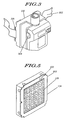
- a typical powered-air respiratory system will include a head cover having a face shield and a belt-worn air filter unit which provides a flow of filtered air to the head cover via a breathing tube.
- the air filter unit will contain within its housing a filter such as a high efficiency particulate air (HEPA) filter or other type of filter for filtering out the impurities in the environment.
- HEPA high efficiency particulate air
- ambient air is drawn through the belt-mounted air filter unit by a conventional blower motor/impeller assembly (hereinafter referred simply as the "blower motor assembly").
- the unfiltered air is then drawn through the air unit's internal filter and the filtered air is then sent into the head cover.
- the present invention provides for a respiratory system with a filter which can keep track of its usage via a storage device located in the filter (filter assembly) which communicates with the personal respiratory system the filter is used in.
- the storage device keeps track of the filter's usage even if the filter is used in more than one filtering system.
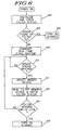
- a filtering system in another embodiment, includes a filter unit which communicates with a filter having a storage device. During operation, the filtering system periodically updates the storage device found in the filter with regards to the filter's usage. Upon the filter reaching its predetermined end-of-life condition, the filtering system can alert the user of the filter's end-of-life condition via either visual or audio alerts or both.
- the LED 132 can be mounted anywhere on housing 134, but preferably in a location which is conspicuous. Instead of, but preferably in addition to LED 132, an audio indicator, such as a piezo alarm (see item 202 at FIG. 2), is included in order to provide an audible alert to the system user of "end of filter life" and other system conditions.
- an audio indicator such as a piezo alarm (see item 202 at FIG. 2), is included in order to provide an audible alert to the system user of "end of filter life" and other system conditions.
Description
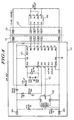
| REFERENCE # | DESCRIPTION |
| Parts List for Air Unit Board Assembly (AUBA) | |
| C102, C303 | CAPACITOR, 33 PF, 5%, 5OV WPO Ceramic (SM 0805) |
| C101 | CAPACITOR, 47 uF, 20%, 6.3V Tantalum (SM CHIP) |
| F101 | CRYSTAL, 32,768 Hz Rs, 50K DL, Cp .85 pF (SMD) |
| CR101 | DIODE, LED Red Diffused 20 mcd 10mn (SM MELF) |
| CR102 | DIODE, Shotky PRV 20 vf .45V LA (SM MELF) |
| 408 | IC, Comparator Low Pwr 2.5V (min) w/Vref (SOICS) |
| 410 | IC, LP uC PIC16LC54A*, 512 EPROM, 32 RAM, OTP LV (SOICS) |
| --- | LIGHT PIPE, FOR CR102 |
| AUBAPCB | PCB, .062" FR-4 SMT SS SM |
| R104 | RESISTOR, 10K OHM 5% 1/1OW Thin Film (SM 0805) |
| R103 | RESISTOR, 68 OHM 5% 1/1OW Metal Film (SM 0805) |
| R102 | RESISTOR, 698K OHM 1% 1/10W Metal Film (SM 0805) |
| R101 | RESISTOR, 825k OHM 1% 1/10W Metal Film (SM 0805) |
| alternate Part: PIC16LV54A-/80 | |
| Parts List for Filter Board Assembly | |
| C201 | CAPACITOR, .01 uF 10% 50V X7R Ceramic (SM 0805) |
| 402 | IC, 256-bit serial EEPROM for 2V-5.5V op (S0IC8) |
| FBAPCB | PCT, .062" FR-4 SOLE SIDED SLK SCRB SOLDER MSK |
Claims (8)
- A respiratory system (100) configured for supplying clean air to a person being connected to the system, the respiratory system (100) comprising:a head cover (102);a removable filter assembly (124) through which air passes before entering the head cover (102), the removable filter assembly (124) including a filter element (128) and a nonvolatile memory device (402) attached to the filter element (128); andan air unit (130) including a blower motor assembly (118) and a controller circuit (114), the controller circuit (114) determines the amount of time the blower motor assembly (118) is operational and provides an update signal for storage in the nonvolatile memory device (402) which is indicative of the length of time the blower motor has been operational.
- A respiratory system (100) as defined in claim 1, wherein the controller circuit (114) periodically updates the nonvolatile memory device (402) by sending periodic update signals during the time the blower motor assembly (118) is operational.
- A respiratory system (100) as defined in claim 1, wherein the air unit (130) and replaceable filter assembly (124) both include connectors (122) which allow for the electrical interconnection of the controller (114) and the nonvolatile memory device (402).
- A respiratory system (100) as defined in any of claims 1 to 3 further comprising a controller (410) for monitoring the amount of time the filter assembly (124) is operational and periodically sending an update signal to the nonvolatile memory device (402).
- A respiratory system (100) as defined in claim 4, wherein the update signal causes a filter usage value stored in the nonvolatile memory device (402) to change, the filter usage value providing an indication on the amount of time the filter element (128) has been in use.
- A respiratory system (100) as defined in claim 5, wherein the controller (410) periodically compares the filter usage value to a filter life threshold value to determine if the filter element (128) has reached its end-of-life condition.
- A respiratory system (100) as defined in claim 6 further comprising an annunicator and the controller (410) causes the annunicator to provide an alert if the controller (410) determines that the filter element (128) has reached its end-of-life condition.
- A respiratory system (100) as defined in claim 6, wherein the respiratory system (100) comprises a powered-air respiratory system which includes an air unit (130) having a blower motor assembly (118), and the controller (410) determines the amount of time the blower motor assembly (118) is operational and sends the update signal to the input port periodically as long as the blower motor assembly (118) is operational.
Applications Claiming Priority (3)
| Application Number | Priority Date | Filing Date | Title |
|---|---|---|---|
| US818797 | 1997-03-14 | ||
| US08/818,797 US6186140B1 (en) | 1997-03-14 | 1997-03-14 | Respiratory filter element having a storage device for keeping track of filter usage and a system for use therewith |
| PCT/US1998/004660 WO1998041306A1 (en) | 1997-03-14 | 1998-03-11 | A filter element having a storage device for keeping track of filter usage and a system for use therewith |
Publications (2)
| Publication Number | Publication Date |
|---|---|
| EP0975410A1 EP0975410A1 (en) | 2000-02-02 |
| EP0975410B1 true EP0975410B1 (en) | 2005-02-16 |
Family
ID=25226434
Family Applications (1)
| Application Number | Title | Priority Date | Filing Date |
|---|---|---|---|
| EP98910283A Expired - Lifetime EP0975410B1 (en) | 1997-03-14 | 1998-03-11 | A filter element having a storage device for keeping track of filter usage and a system for use therewith |
Country Status (9)
| Country | Link |
|---|---|
| US (1) | US6186140B1 (en) |
| EP (1) | EP0975410B1 (en) |
| JP (2) | JP2001516277A (en) |
| KR (1) | KR100540610B1 (en) |
| AU (1) | AU6456498A (en) |
| BR (1) | BR9808243A (en) |
| DE (1) | DE69829046T2 (en) |
| ES (1) | ES2235319T3 (en) |
| WO (1) | WO1998041306A1 (en) |
Cited By (1)
| Publication number | Priority date | Publication date | Assignee | Title |
|---|---|---|---|---|
| WO2021207268A1 (en) * | 2020-04-07 | 2021-10-14 | Abc Filtration Corp. | Improved papr with viral resistant coatings |
Families Citing this family (117)
| Publication number | Priority date | Publication date | Assignee | Title |
|---|---|---|---|---|
| GB9826671D0 (en) * | 1998-12-03 | 1999-01-27 | Process Scient Innovations | Filters and active devices |
| DK1135202T3 (en) | 1998-12-03 | 2003-10-27 | Psi Global Ltd | Compressor or vacuum pump using fluid filters with hidden machine readable identification |
| ATE342084T1 (en) | 1999-08-05 | 2006-11-15 | Map Medizin Technologie Gmbh | DEVICE FOR SUPPLYING A BREATHING GAS AND HUMIDIFIER DEVICE |
| US6391102B1 (en) * | 2000-03-21 | 2002-05-21 | Stackhouse, Inc. | Air filtration system with filter efficiency management |
| US6866717B2 (en) * | 2000-10-05 | 2005-03-15 | Nordson Corporation | Powder coating spray booth with air curtain |
| US20020082746A1 (en) * | 2000-12-27 | 2002-06-27 | Honeywell International Inc. | Replaceable media with programmable device |
| US6666209B2 (en) * | 2001-02-20 | 2003-12-23 | 3M Innovative Properties Company | Method and system of calibrating air flow in a respirator system |
| US7091795B1 (en) | 2001-10-09 | 2006-08-15 | Zilog, Inc. | Modulating ramp angle in a digital frequency locked loop |
| US6636122B2 (en) * | 2001-10-09 | 2003-10-21 | Zilog, Inc. | Analog frequency locked loop with digital oversampling feedback control and filter |
| DE10151271B4 (en) * | 2001-10-17 | 2010-01-07 | Sartorius Stedim Biotech Gmbh | Method for performing integrity tests of filter elements |
| DE10151269B4 (en) * | 2001-10-17 | 2005-08-25 | Sartorius Ag | Method for monitoring the integrity of filtration plants |
| DE10160429B4 (en) * | 2001-12-08 | 2008-05-08 | Sartorius Stedim Biotech Gmbh | Filter with an electronic memory element |
| US6834646B2 (en) * | 2001-12-19 | 2004-12-28 | Testa Technologies T.T. Ltd. | Respiratory hood |
| US6610121B2 (en) | 2002-01-09 | 2003-08-26 | Hp Intellectual Corp. | Odor removal system |
| US6660060B2 (en) | 2002-01-09 | 2003-12-09 | Hp Intellectual Corp. | Air filtering system |
| AU2003217428A1 (en) * | 2002-02-15 | 2003-09-09 | Cuno Incorporated | System for monitoring the performance of fluid treatment cartridges |
| US7638042B2 (en) * | 2002-02-15 | 2009-12-29 | 3M Innovative Properties Company | System for monitoring the performance of fluid treatment cartridges |
| JP2005527771A (en) * | 2002-05-23 | 2005-09-15 | キュノ・エンジニアド・プロダクツ,インコーポレーテッド | Water filter assembly |
| US6984256B2 (en) * | 2002-06-28 | 2006-01-10 | Creo Inc. | System for collecting and filtering imaging by-products |
| FR2848291B1 (en) * | 2002-12-06 | 2005-02-04 | Delta Prot | VENTILATION BLOCK FOR GARMENT AS A SCAPHANDRE OR THE LIKE |
| US6785981B1 (en) | 2003-02-19 | 2004-09-07 | In-O-Vate Technologies | Restriction detecting systems for clothes dryer exhaust systems |
| US20040182394A1 (en) * | 2003-03-21 | 2004-09-23 | Alvey Jeffrey Arthur | Powered air purifying respirator system and self contained breathing apparatus |
| US20060048777A1 (en) * | 2003-03-21 | 2006-03-09 | Interspiro, Inc. | Apparatus and method for providing breathable air and bodily protection in a contaminated environment |
| AU2003903139A0 (en) * | 2003-06-20 | 2003-07-03 | Resmed Limited | Breathable gas apparatus with humidifier |
| NZ710686A (en) | 2003-06-20 | 2017-02-24 | Resmed Ltd | Breathable gas apparatus with humidifier |
| US7647927B2 (en) | 2003-08-22 | 2010-01-19 | Wilcox Industries Corp. | Self-contained breathing system |
| US7481917B2 (en) | 2004-03-05 | 2009-01-27 | Hydranautics | Filtration devices with embedded radio frequency identification (RFID) tags |
| US7320722B2 (en) * | 2004-10-29 | 2008-01-22 | 3M Innovative Properties Company | Respiratory protection device that has rapid threaded clean air source attachment |
| GB2420083A (en) * | 2004-11-11 | 2006-05-17 | Reckitt Benckiser Inc | Air purifier |
| DE102005007020A1 (en) * | 2005-02-15 | 2006-08-24 | Mann + Hummel Gmbh | Device for monitoring wear parts |
| WO2006092001A1 (en) * | 2005-03-01 | 2006-09-08 | Resmed Limited | Recognition system for an apparatus that delivers breathable gas to a patient |
| US7419526B2 (en) * | 2005-03-03 | 2008-09-02 | 3M Innovative Properties Company | Conformal filter cartridges and methods |
| DE102005013672A1 (en) * | 2005-03-24 | 2006-09-28 | Hydac Filtertechnik Gmbh | filter means |
| US20090044129A1 (en) * | 2005-06-09 | 2009-02-12 | Whirlpool Corporation | Graphical user interface to control interactions between an appliance and a consumable holder |
| EP2228969B1 (en) * | 2005-06-09 | 2017-04-19 | Whirlpool Corporation | Software architecture system and method for communication with, and management of, at least one component within a household appliance |
| US20090044137A1 (en) * | 2005-06-09 | 2009-02-12 | Whirlpool Corporation | Consumable holder with user interface data |
| US8442042B2 (en) * | 2005-06-09 | 2013-05-14 | Whirlpool Corporation | Appliance and a consumable holder with an embedded virtual router |
| US8477007B2 (en) * | 2005-06-09 | 2013-07-02 | Whirlpool Corporation | Appliance and a consumable holder in a network |
| US8395476B2 (en) * | 2005-06-09 | 2013-03-12 | Whirlpool Corporation | Consumable holder with taxonomy |
| US20090040066A1 (en) * | 2005-06-09 | 2009-02-12 | Whirlpool Corporation | Consumable holder with routable data packet for an appliance |
| US8264318B2 (en) * | 2005-06-09 | 2012-09-11 | Whirlpool Corporation | Consumable holder with converter |
| US8314678B2 (en) * | 2005-06-09 | 2012-11-20 | Whirlpool Corporation | Consumable holder with a cycle structure for an appliance |
| EP1937386B1 (en) | 2005-09-07 | 2013-12-25 | Hydranautics | Reverse osmosis filtration devices with rfid tag-powered flow and conductivity meters |
| EP3300757B1 (en) * | 2005-12-21 | 2019-07-17 | ResMed Pty Ltd | Identification system and method for mask and ventilator components |
| WO2007098540A1 (en) * | 2006-03-01 | 2007-09-07 | Resmed Ltd | Method and apparatus for reminding user to replace and/or service cpap apparatus and/or component thereof |
| CN101443098A (en) | 2006-03-13 | 2009-05-27 | 海德拉罗迪克斯公司 | Device for measuring permeate flow and permeate conductivity of individual reverse osmosis membrane elements |
| US20070272244A1 (en) * | 2006-04-25 | 2007-11-29 | Witmer Warner H | Fluidic barrier |
| US20070283961A1 (en) * | 2006-06-07 | 2007-12-13 | Hsieh Hsin-Mao | Air purifier for a protective garment |
| WO2008118768A1 (en) * | 2007-03-23 | 2008-10-02 | 3M Innovative Properties Company | Air delivery apparatus for respirator hood |
| US20080271739A1 (en) | 2007-05-03 | 2008-11-06 | 3M Innovative Properties Company | Maintenance-free respirator that has concave portions on opposing sides of mask top section |
| US9770611B2 (en) | 2007-05-03 | 2017-09-26 | 3M Innovative Properties Company | Maintenance-free anti-fog respirator |
| US8365726B2 (en) | 2007-06-07 | 2013-02-05 | Resmed Limited | Tub for humidifier |
| PL2186041T3 (en) | 2007-08-31 | 2018-08-31 | 3M Innovative Properties Company | Determining conditions of personal protection articles against at least one criterion |
| PL2183030T3 (en) | 2007-08-31 | 2017-09-29 | 3M Innovative Properties Company | Determining conditions of components removably coupled to personal protection equipment |
| JP2010540174A (en) * | 2007-10-05 | 2010-12-24 | スリーエム イノベイティブ プロパティズ カンパニー | Respirator hose, mounting apparatus and method |
| CA2720226C (en) * | 2008-04-04 | 2017-09-19 | Pierre Legare | Air filtration device |
| US8328903B2 (en) * | 2008-05-30 | 2012-12-11 | Scott Technologies, Inc. | Determining effluent concentration profiles and service lives of air purifying respirator cartridges |
| US8337602B2 (en) * | 2008-10-15 | 2012-12-25 | Tf Industries, Llc | Deodorizing device and kit, and methods for odor removal |
| US8461959B2 (en) * | 2008-10-23 | 2013-06-11 | Whirlpool Corporation | Consumable holder with process control apparatus |
| US20100125364A1 (en) * | 2008-11-20 | 2010-05-20 | Whirlpool Corporation | Configurable consumable holder for an appliance |
| US20100102051A1 (en) * | 2008-10-23 | 2010-04-29 | Whirlpool Corporation | Consumable holder with electronics to communicate with an appliance |
| US8118997B2 (en) * | 2008-10-23 | 2012-02-21 | Whirlpool Corporation | Smart filter for an appliance |
| US8010211B2 (en) * | 2008-10-23 | 2011-08-30 | Whirlpool Corporation | Appliance with a service interface for communicating with a consumable holder |
| US7860662B2 (en) * | 2008-12-17 | 2010-12-28 | Scott Technologies, Inc. | Systems and methods for determining filter service lives |
| TW201034710A (en) * | 2009-03-31 | 2010-10-01 | Top Vision Medical Equipment Consultant Co Ltd | Gas supply device capable of sensing and displaying concentration of suspended particles |
| US8372186B2 (en) | 2009-08-14 | 2013-02-12 | Gregory J. Dobbyn | Ductless fume hood gas monitoring and detection system |
| WO2011031466A2 (en) * | 2009-08-25 | 2011-03-17 | Sunbeam Products, Inc. | Filter recognition system |
| GB2474917B (en) * | 2009-11-02 | 2015-12-23 | Scott Health & Safety Ltd | Improvements to powered air breathing apparatus |
| US9696243B2 (en) * | 2010-01-12 | 2017-07-04 | Jose Lopez | Fluid sampling system |
| WO2011156609A2 (en) | 2010-06-09 | 2011-12-15 | Cummins Filtration Ip Inc. | System for monitoring and indicating filter life |
| BR112012020926A2 (en) | 2010-06-17 | 2016-05-03 | Cummins Filtration Ip Inc | method for providing the internal combustion engine user with the economically optimal air filter replacement range |
| US9428237B2 (en) | 2010-09-01 | 2016-08-30 | Peer Toftner | Motorcycle with adjustable geometry |
| CA2810649A1 (en) * | 2010-09-07 | 2012-03-15 | Nextteq Llc | Remaining service life indication system for gas mask cartridges and canisters |
| US9700743B2 (en) | 2012-07-31 | 2017-07-11 | 3M Innovative Properties Company | Respiratory assembly including latching mechanism |
| KR20140068041A (en) | 2011-08-01 | 2014-06-05 | 쓰리엠 이노베이티브 프로퍼티즈 캄파니 | Respiratory assembly including latching mechanism |
| US9192795B2 (en) | 2011-10-07 | 2015-11-24 | Honeywell International Inc. | System and method of calibration in a powered air purifying respirator |
| US9808656B2 (en) | 2012-01-09 | 2017-11-07 | Honeywell International Inc. | System and method of oxygen deficiency warning in a powered air purifying respirator |
| US9510626B2 (en) | 2013-02-01 | 2016-12-06 | 3M Innovative Properties Company | Sleeve-fit respirator cartridge |
| DE102013015122A1 (en) * | 2013-02-08 | 2014-08-14 | Diehl Ako Stiftung & Co. Kg | A method of monitoring airflow in an airflow channel |
| WO2014194050A1 (en) * | 2013-05-30 | 2014-12-04 | Scott Technologies, Inc. | Pump panel accountability device and method of use |
| EP4272840A1 (en) | 2013-07-15 | 2023-11-08 | 3M Innovative Properties Co. | Respirator having optically active exhalation valve |
| USD746974S1 (en) | 2013-07-15 | 2016-01-05 | 3M Innovative Properties Company | Exhalation valve flap |
| US10213629B2 (en) * | 2013-07-19 | 2019-02-26 | Honeywell International Inc. | End of service life indicator for a respirator |
| WO2015131243A1 (en) * | 2014-03-03 | 2015-09-11 | Killara I.P. Pty Ltd | Medical air supply system |
| KR101579438B1 (en) * | 2014-07-02 | 2015-12-23 | 주식회사 오토스윙 | Information detectable structure of filter installed in pure air supplier of Respirator and method thereof |
| KR20160004079A (en) * | 2014-07-02 | 2016-01-12 | 주식회사 오토스윙 | Method for emergency warnining of pure air supplier of Respirator |
| ES2752078T3 (en) * | 2015-01-14 | 2020-04-02 | CleanSpace IP Pty Ltd | Filter unit for a breathing apparatus |
| GB201508114D0 (en) | 2015-05-12 | 2015-06-24 | 3M Innovative Properties Co | Respirator tab |
| USD820455S1 (en) | 2015-06-09 | 2018-06-12 | Lincoln Global, Inc. | Filter cover of a powered air purifying respirator |
| USD810299S1 (en) | 2015-06-09 | 2018-02-13 | Lincoln Global, Inc. | Battery of a powered air purifying respirator |
| USD822210S1 (en) | 2015-06-09 | 2018-07-03 | Lincoln Global, Inc. | Extended battery of a powered air purifying respirator |
| USD820456S1 (en) | 2015-06-09 | 2018-06-12 | Lincoln Global, Inc. | Belt bracket of powered air purifying respirator |
| CN205090507U (en) | 2015-09-30 | 2016-03-16 | 飞利浦(中国)投资有限公司 | Air -purifying device |
| RU2715116C1 (en) | 2016-06-23 | 2020-02-25 | Зм Инновейтив Пропертиз Компани | Welding shield with detection of external action for anticipatory prevention of hazardous effect in welding |
| US10610708B2 (en) | 2016-06-23 | 2020-04-07 | 3M Innovative Properties Company | Indicating hazardous exposure in a supplied air respirator system |
| US9998804B2 (en) | 2016-06-23 | 2018-06-12 | 3M Innovative Properties Company | Personal protective equipment (PPE) with analytical stream processing for safety event detection |
| US9848666B1 (en) | 2016-06-23 | 2017-12-26 | 3M Innovative Properties Company | Retrofit sensor module for a protective head top |
| US11023818B2 (en) | 2016-06-23 | 2021-06-01 | 3M Innovative Properties Company | Personal protective equipment system having analytics engine with integrated monitoring, alerting, and predictive safety event avoidance |
| US11260251B2 (en) | 2016-06-23 | 2022-03-01 | 3M Innovative Properties Company | Respirator device with light exposure detection |
| CN106620979B (en) * | 2016-12-29 | 2019-09-17 | 天津怡和嘉业医疗科技有限公司 | A kind of ventilator control method and device |
| CN110573454B (en) | 2017-02-27 | 2021-08-20 | 第三极股份有限公司 | System and method for generating nitric oxide |
| MX2020010523A (en) | 2017-02-27 | 2021-02-09 | Third Pole Inc | Systems and methods for generating nitric oxide. |
| CA3054660C (en) | 2017-02-27 | 2022-05-03 | Third Pole, Inc. | Systems and methods for ambulatory generation of nitric oxide |
| US11813581B2 (en) | 2017-07-14 | 2023-11-14 | 3M Innovative Properties Company | Method and adapter for conveying plural liquid streams |
| USD853044S1 (en) | 2018-03-07 | 2019-07-02 | Lincoln Global, Inc. | Inner shell of a helmet |
| USD848077S1 (en) | 2018-03-07 | 2019-05-07 | Lincoln Global, Inc. | Cover lens frame |
| USD857306S1 (en) | 2018-03-07 | 2019-08-20 | Lincoln Global, Inc. | Top of helmet shell |
| USD860546S1 (en) | 2018-03-07 | 2019-09-17 | Lincoln Global, Inc. | Top shell for helmet |
| USD851841S1 (en) | 2018-03-23 | 2019-06-18 | Lincoln Global, Inc. | Shield holder frame |
| CN114375284A (en) | 2019-05-15 | 2022-04-19 | 第三极股份有限公司 | System and method for generating nitric oxide |
| US11045620B2 (en) | 2019-05-15 | 2021-06-29 | Third Pole, Inc. | Electrodes for nitric oxide generation |
| CN110465013B (en) * | 2019-08-15 | 2020-12-29 | 深圳市荣盛智能装备有限公司 | Method and device for detecting residual service time of air respirator and storage medium |
| EP4069069A1 (en) | 2020-01-11 | 2022-10-12 | Third Pole, Inc. | Systems and methods for nitric oxide generation with humidity control |
| EP3915646A1 (en) * | 2020-05-27 | 2021-12-01 | Optrel Holding AG | Fan device for a respiratory protection system |
| TR202009416A2 (en) * | 2020-06-17 | 2020-07-21 | Maltepe Ueniversitesi Teknoloji Transfer Ofisi Anonim Sirketi | DISINFECTED AIR FLOW PROTECTION VENT HEAD |
| WO2021258025A1 (en) | 2020-06-18 | 2021-12-23 | Third Pole, Inc. | Systems and methods for preventing and treating infections with nitric oxide |
| US20220226676A1 (en) * | 2021-01-19 | 2022-07-21 | American PAPR LLC | Powered air purifying respirator |
Citations (1)
| Publication number | Priority date | Publication date | Assignee | Title |
|---|---|---|---|---|
| US5303701A (en) * | 1991-10-07 | 1994-04-19 | Dragerwerk Ag | Blower-supported gas mask and breathing equipment with an attachable control part |
Family Cites Families (42)
| Publication number | Priority date | Publication date | Assignee | Title |
|---|---|---|---|---|
| US1537519A (en) | 1924-12-05 | 1925-05-12 | Yablick Max | Indicating gas-mask canister |
| US3027865A (en) | 1959-01-06 | 1962-04-03 | Honeywell Regulator Co | Clogged filter indicator |
| US3201772A (en) | 1961-12-22 | 1965-08-17 | Gen Electric | Filter obstruction signal arrangement for air conditioning apparatus |
| US3250873A (en) * | 1964-03-20 | 1966-05-10 | Marvel Eng Co | Filter signal |
| US3718982A (en) | 1971-10-27 | 1973-03-06 | Gen Motors Corp | Excess lint indicator for a clothes dryer |
| US3740931A (en) | 1971-12-15 | 1973-06-26 | R Nowicki | Automobile and truck carburator air intake filters |
| JPS4944844U (en) | 1972-07-28 | 1974-04-19 | ||
| US4050291A (en) | 1972-09-27 | 1977-09-27 | Honeywell Inc. | Filter condition responsive device compensated for changes in medium flow |
| US3966440A (en) | 1975-06-03 | 1976-06-29 | Catalyst Research Corporation | Colorimetric vinyl chloride indicator |
| US4014209A (en) | 1975-12-15 | 1977-03-29 | Emerick Wayne L | Air filter condition indicating device |
| US4040042A (en) | 1976-07-13 | 1977-08-02 | Horst Mayer | Exhaust apparatus and monitoring circuit therefor |
| US4155358A (en) | 1976-12-13 | 1979-05-22 | Minnesota Mining And Manufacturing Company | Respirator |
| US4154586A (en) | 1978-01-13 | 1979-05-15 | American Optical Corporation | Respirator cartridge end-of-service lift indicator system and method of making |
| US4365627A (en) | 1980-09-22 | 1982-12-28 | The Dow Chemical Company | Filter-type respirator canister |
| US4543314A (en) * | 1983-12-01 | 1985-09-24 | Xerox Corporation | Process for preparing electrostatographic photosensitive device comprising sodium additives and trigonal selenium particles |
| US4623451A (en) | 1985-02-19 | 1986-11-18 | Oliver Bruce J | Third faucet system with above sink purity indicator |
| US4698164A (en) | 1985-07-29 | 1987-10-06 | Kinetico, Inc. | Filter apparatus |
| US4610703A (en) | 1986-01-31 | 1986-09-09 | Thaddeus Kowalczyk | Air purifier for protecting motor vechicle occupants from pollution |
| US4925551A (en) | 1986-03-21 | 1990-05-15 | Alfred J. Lipshultz | Portable water purification system including electronic memory panel assembly |
| DE3613512C3 (en) * | 1986-04-22 | 1994-09-29 | Auergesellschaft Gmbh | Electrical warning device for displaying the state of exhaustion of a gas filter which retains harmful gases |
| US4772386A (en) | 1986-05-30 | 1988-09-20 | Autotrol Corporation | Filter with liquid meter |
| US4762611A (en) | 1987-09-16 | 1988-08-09 | Myron L Company, Inc. | Water quality indication system |
| US4851818A (en) | 1988-04-01 | 1989-07-25 | Eastman Kodak Company | Electronic controller for a water purifying unit |
| US4918426A (en) | 1988-05-02 | 1990-04-17 | Amway Corporation | Method and apparatus for sensing fluid flow volume to indicate end of filter life |
| DE3818052A1 (en) * | 1988-05-27 | 1989-12-07 | Geraetebau Gmbh | RESPIRATORY MASK |
| DE3914664A1 (en) * | 1989-05-03 | 1990-11-08 | Joseph Stetter | Exhaustion sensor and indicator e.g. for gas mask - gives real-time warning of saturation of absorbent material by measurement of electrical conductivity of coating |
| DE3918561C2 (en) | 1989-06-07 | 1997-09-11 | Brita Wasserfilter | Water treatment device |
| US4999101A (en) | 1989-11-02 | 1991-03-12 | Alusuisse Lonza-Services Ltd | Preheat indicator |
| DE4009107A1 (en) * | 1990-03-21 | 1991-09-26 | Auergesellschaft Gmbh | WARNING DEVICE WITH A MEASURING CELL AND ALARMS TO INDICATE THE DEFAULT OF A GAS FILTER |
| DE4014442A1 (en) | 1990-05-05 | 1991-11-07 | Duepro Ag | DEVICE FOR DISPLAYING THE DEGREE OF POLLUTION OF AIR FILTERS IN SUCTION CLEANING DEVICES, ROOM FILTERS OR THE LIKE. |
| US5131932A (en) | 1990-09-11 | 1992-07-21 | Bionaire, Inc. | Filter replacement indicator |
| US5236477A (en) | 1991-11-05 | 1993-08-17 | Kabushiki Kaisha Toshiba | Microcomputer-based control device |
| US5190643A (en) | 1992-01-10 | 1993-03-02 | Mr. Coffee, Inc. | Water treatment device having means to count times used and limit useage |
| DE4202025C2 (en) * | 1992-01-25 | 1995-02-02 | Draegerwerk Ag | Fan-assisted breathing apparatus with adjustable fan performance |
| EP0566479B1 (en) | 1992-04-14 | 1995-11-15 | Roger Claude Robin | Fouling detector for air filter |
| US5236578A (en) | 1992-07-07 | 1993-08-17 | American Home Water Products Corporation | Filter life indicator for water purification system using magnetically actuated switch |
| US5362383A (en) | 1993-01-13 | 1994-11-08 | Ecowater Systems, Inc. | Self-contained reverse osmosis electronic monitoring system |
| NL9300554A (en) | 1993-03-29 | 1994-10-17 | Doctro A V V | Assembly of filter device and a replaceable filter; as well as filter device and filter for use therein. |
| US5378254A (en) | 1993-10-15 | 1995-01-03 | Vaportek, Inc. | Filter sensing apparatus and filter therefor |
| DE9407866U1 (en) * | 1994-05-11 | 1994-07-14 | Ind Tech Res Inst | Gas mask with a display device |
| TW287952B (en) * | 1994-08-31 | 1996-10-11 | Lifepro Inc | |
| US5666949A (en) * | 1994-10-24 | 1997-09-16 | Minnesota Mining And Manufacturing Company | Exposure indicator with continuous alarm signal indicating multiple conditions |
-
1997
- 1997-03-14 US US08/818,797 patent/US6186140B1/en not_active Expired - Fee Related
-
1998
- 1998-03-11 DE DE69829046T patent/DE69829046T2/en not_active Expired - Lifetime
- 1998-03-11 JP JP54058398A patent/JP2001516277A/en not_active Withdrawn
- 1998-03-11 KR KR1019997008295A patent/KR100540610B1/en not_active IP Right Cessation
- 1998-03-11 WO PCT/US1998/004660 patent/WO1998041306A1/en active IP Right Grant
- 1998-03-11 ES ES98910283T patent/ES2235319T3/en not_active Expired - Lifetime
- 1998-03-11 EP EP98910283A patent/EP0975410B1/en not_active Expired - Lifetime
- 1998-03-11 AU AU64564/98A patent/AU6456498A/en not_active Abandoned
- 1998-03-11 BR BR9808243-4A patent/BR9808243A/en not_active IP Right Cessation
-
2009
- 2009-08-14 JP JP2009188085A patent/JP2010000368A/en active Pending
Patent Citations (1)
| Publication number | Priority date | Publication date | Assignee | Title |
|---|---|---|---|---|
| US5303701A (en) * | 1991-10-07 | 1994-04-19 | Dragerwerk Ag | Blower-supported gas mask and breathing equipment with an attachable control part |
Cited By (1)
| Publication number | Priority date | Publication date | Assignee | Title |
|---|---|---|---|---|
| WO2021207268A1 (en) * | 2020-04-07 | 2021-10-14 | Abc Filtration Corp. | Improved papr with viral resistant coatings |
Also Published As
| Publication number | Publication date |
|---|---|
| US6186140B1 (en) | 2001-02-13 |
| WO1998041306A1 (en) | 1998-09-24 |
| EP0975410A1 (en) | 2000-02-02 |
| DE69829046T2 (en) | 2006-03-16 |
| JP2010000368A (en) | 2010-01-07 |
| DE69829046D1 (en) | 2005-03-24 |
| JP2001516277A (en) | 2001-09-25 |
| AU6456498A (en) | 1998-10-12 |
| BR9808243A (en) | 2000-05-16 |
| KR100540610B1 (en) | 2006-01-12 |
| ES2235319T3 (en) | 2005-07-01 |
| KR20000076201A (en) | 2000-12-26 |
Similar Documents
| Publication | Publication Date | Title |
|---|---|---|
| EP0975410B1 (en) | A filter element having a storage device for keeping track of filter usage and a system for use therewith | |
| EP1305083B1 (en) | Apparatus and method for breathing apparatus component coupling | |
| EP2496312B1 (en) | Improvements to powered air breathing apparatus | |
| CA2706376C (en) | Modular powered air purifying respirator | |
| CN107206261B (en) | A filtering component for respiratory device | |
| US10888721B2 (en) | Breath responsive powered air purifying respirator | |
| JP6316257B2 (en) | Electric air purifying respirator | |
| KR101242608B1 (en) | Portable air filters | |
| AU2001236735A1 (en) | Apparatus and method for breathing apparatus component coupling | |
| US20090314295A1 (en) | Powered air purifying respirator | |
| KR102035977B1 (en) | Air cleaning mask device | |
| EP0164946A2 (en) | Improvements in and relating to respirators | |
| AU2010313376A1 (en) | Method of controlling a powered air purifying respirator | |
| CN116867550A (en) | Mask device and control method thereof | |
| WO2018106258A1 (en) | End of service life indicator for a disposable face mask. | |
| US20110126716A1 (en) | Dust-collecting apparatus | |
| CN213667622U (en) | Take disconnect-type drive filter respirator that driving fit detected | |
| CN212118795U (en) | Respiratory protection device and protection wearing system | |
| CN100403949C (en) | Ventilation unit which can be dressed like a tight suit or similar | |
| MXPA99008154A (en) | A filter element having a storage device for keeping track of filter usage and a system for use therewith | |
| CN213609492U (en) | Integrated driving filtering respirator with tightness detection function | |
| CN116785606A (en) | Air filtering unit with tracking function and electric air purifying respirator provided with same | |
| CN212282582U (en) | Emergency drilling is with breathing mask convenient to wear | |
| CN217725584U (en) | Gas cylinder cabinet for laboratory | |
| CN213555881U (en) | Power air supply filtering main machine body compatible with filter element and filter tank |
Legal Events
| Date | Code | Title | Description |
|---|---|---|---|
| PUAI | Public reference made under article 153(3) epc to a published international application that has entered the european phase |
Free format text: ORIGINAL CODE: 0009012 |
|
| 17P | Request for examination filed |
Effective date: 19991012 |
|
| AK | Designated contracting states |
Kind code of ref document: A1 Designated state(s): DE ES FR GB IT NL |
|
| 17Q | First examination report despatched |
Effective date: 20010516 |
|
| GRAP | Despatch of communication of intention to grant a patent |
Free format text: ORIGINAL CODE: EPIDOSNIGR1 |
|
| GRAS | Grant fee paid |
Free format text: ORIGINAL CODE: EPIDOSNIGR3 |
|
| GRAA | (expected) grant |
Free format text: ORIGINAL CODE: 0009210 |
|
| AK | Designated contracting states |
Kind code of ref document: B1 Designated state(s): DE ES FR GB IT NL |
|
| PG25 | Lapsed in a contracting state [announced via postgrant information from national office to epo] |
Ref country code: NL Free format text: LAPSE BECAUSE OF FAILURE TO SUBMIT A TRANSLATION OF THE DESCRIPTION OR TO PAY THE FEE WITHIN THE PRESCRIBED TIME-LIMIT Effective date: 20050216 |
|
| REG | Reference to a national code |
Ref country code: GB Ref legal event code: FG4D |
|
| REF | Corresponds to: |
Ref document number: 69829046 Country of ref document: DE Date of ref document: 20050324 Kind code of ref document: P |
|
| REG | Reference to a national code |
Ref country code: ES Ref legal event code: FG2A Ref document number: 2235319 Country of ref document: ES Kind code of ref document: T3 |
|
| NLV1 | Nl: lapsed or annulled due to failure to fulfill the requirements of art. 29p and 29m of the patents act | ||
| PLBE | No opposition filed within time limit |
Free format text: ORIGINAL CODE: 0009261 |
|
| STAA | Information on the status of an ep patent application or granted ep patent |
Free format text: STATUS: NO OPPOSITION FILED WITHIN TIME LIMIT |
|
| ET | Fr: translation filed | ||
| 26N | No opposition filed |
Effective date: 20051117 |
|
| PGFP | Annual fee paid to national office [announced via postgrant information from national office to epo] |
Ref country code: IT Payment date: 20060331 Year of fee payment: 9 |
|
| PGFP | Annual fee paid to national office [announced via postgrant information from national office to epo] |
Ref country code: ES Payment date: 20070326 Year of fee payment: 10 |
|
| PGFP | Annual fee paid to national office [announced via postgrant information from national office to epo] |
Ref country code: FR Payment date: 20070319 Year of fee payment: 10 |
|
| REG | Reference to a national code |
Ref country code: FR Ref legal event code: ST Effective date: 20081125 |
|
| PG25 | Lapsed in a contracting state [announced via postgrant information from national office to epo] |
Ref country code: FR Free format text: LAPSE BECAUSE OF NON-PAYMENT OF DUE FEES Effective date: 20080331 |
|
| REG | Reference to a national code |
Ref country code: ES Ref legal event code: FD2A Effective date: 20080312 |
|
| PG25 | Lapsed in a contracting state [announced via postgrant information from national office to epo] |
Ref country code: ES Free format text: LAPSE BECAUSE OF NON-PAYMENT OF DUE FEES Effective date: 20080312 |
|
| PG25 | Lapsed in a contracting state [announced via postgrant information from national office to epo] |
Ref country code: IT Free format text: LAPSE BECAUSE OF NON-PAYMENT OF DUE FEES Effective date: 20070311 |
|
| PGFP | Annual fee paid to national office [announced via postgrant information from national office to epo] |
Ref country code: GB Payment date: 20120307 Year of fee payment: 15 |
|
| PGFP | Annual fee paid to national office [announced via postgrant information from national office to epo] |
Ref country code: DE Payment date: 20120411 Year of fee payment: 15 |
|
| GBPC | Gb: european patent ceased through non-payment of renewal fee |
Effective date: 20130311 |
|
| REG | Reference to a national code |
Ref country code: DE Ref legal event code: R119 Ref document number: 69829046 Country of ref document: DE Effective date: 20131001 |
|
| PG25 | Lapsed in a contracting state [announced via postgrant information from national office to epo] |
Ref country code: DE Free format text: LAPSE BECAUSE OF NON-PAYMENT OF DUE FEES Effective date: 20131001 Ref country code: GB Free format text: LAPSE BECAUSE OF NON-PAYMENT OF DUE FEES Effective date: 20130311 |