EP0975454B1 - Rotary hammer - Google Patents
Rotary hammer Download PDFInfo
- Publication number
- EP0975454B1 EP0975454B1 EP98908250A EP98908250A EP0975454B1 EP 0975454 B1 EP0975454 B1 EP 0975454B1 EP 98908250 A EP98908250 A EP 98908250A EP 98908250 A EP98908250 A EP 98908250A EP 0975454 B1 EP0975454 B1 EP 0975454B1
- Authority
- EP
- European Patent Office
- Prior art keywords
- hammer
- sleeve
- coupling
- drive
- switching element
- Prior art date
- Legal status (The legal status is an assumption and is not a legal conclusion. Google has not performed a legal analysis and makes no representation as to the accuracy of the status listed.)
- Expired - Lifetime
Links
Images


Classifications
-
- B—PERFORMING OPERATIONS; TRANSPORTING
- B25—HAND TOOLS; PORTABLE POWER-DRIVEN TOOLS; MANIPULATORS
- B25D—PERCUSSIVE TOOLS
- B25D16/00—Portable percussive machines with superimposed rotation, the rotational movement of the output shaft of a motor being modified to generate axial impacts on the tool bit
- B25D16/006—Mode changers; Mechanisms connected thereto
-
- B—PERFORMING OPERATIONS; TRANSPORTING
- B25—HAND TOOLS; PORTABLE POWER-DRIVEN TOOLS; MANIPULATORS
- B25D—PERCUSSIVE TOOLS
- B25D2211/00—Details of portable percussive tools with electromotor or other motor drive
- B25D2211/003—Crossed drill and motor spindles
Definitions
- the invention relates to a rotary hammer with a hammer housing, an electric motor provided in the hammer housing, a tool holder which is provided at the front end of the hammer housing and which can be rotatingly driven by the electric motor about the spindle axis of the hammer spindle, a hammer mechanism provided in the hammer housing for generating impacts acting on the rear end of a hammer bit or chisel bit inserted into the tool holder, and a switching element which is rotatable from the outside about its main axis and which has a cam section for switching between at least three operating modes, of which the first is pure drilling, the second hammer drilling and the third chiselling.
- switching elements are used, one of which moves the coupling arrangement for the rotary drive in a direction parallel to the axis of the hammer spindle, this parallel movement generally being directed coaxially relative to the axis of the hammer spindle, while the other switching element displaces the coupling arrangement for the activation and deactivation of the hammer mechanism parallel or coaxially relative to the armature shaft.
- the object of the invention is to simplify the structure of a rotary hammer in which the armature shaft of the electric motor is arranged perpendicular to the axis of the rotary hammer spindle by making it possible for switching between at least three operating modes to be effected with a single switching element.
- a rotary hammer of the type mentioned at the beginning in which the armature shaft of the electric motor is arranged perpendicular to the axis of the hammer spindle and the armature shaft can selectively be coupled with a drive shaft for the hammer mechanism, is designed in such a way that the armature shaft drives a drive sleeve which is rotatably arranged on the hammer spindle and which can be coupled with the hammer spindle via a coupling sleeve which sits non-rotatable but axially displaceable on the hammer spindle, that the cam section of the switching element acts on the coupling sleeve via a slider part which can be moved parallel to the axis of the hammer spindle, so that the coupling sleeve can be moved between a position of engagement with the drive sleeve and a release position separated from the drive sleeve, and that an actuating section which is eccentric relative to
- the activation and deactivation of the rotary drive thus takes place by means of a slider part which is arranged between the coupling sleeve and the switching element, so that switching is made possible through action on the slider part at a distance from the actual coupling arrangement for the rotary drive, to which end the slider part can be displaced parallel to the axis of the hammer spindle by the cam section provided at the switching element.
- the movement of the coupling sleeve is brought about in the manner that is usual per se parallel or coaxially relative to the axis of the hammer spindle.
- the activation and deactivation of the hammer mechanism of the rotary hammer according to the invention is achieved by the provision, at the switching element, of an actuating section lying eccentrically relative to its main axis, so that, upon rotation of the switching element arranged immediately adjacent to the coupling part of the drive shaft for the hammer mechanism, the coupling part can be moved between an engagement position, in which it couples the drive shaft for the hammer mechanism with the armature shaft of the electric motor, and a release position, in which the coupling of the armature shaft and the drive shaft is broken.
- the coupling sleeve In a withdrawn position, the coupling sleeve may be in positive engagement with the drive sleeve, and so rotatingly drive the latter and thus the hammer spindle and the tool holder in operation of the rotary hammer, whereas in an advanced position it can be in positive engagement with a housing-fixed zone, in order to thus secure the hammer spindle against rotation, so that in the chisel mode the chisel bit inserted into the tool holder is not rotated.
- the coupling sleeve is expediently spring-loaded in the direction of the withdrawn position, so that, in the event of a misalignment of the sections bringing about the positive engagement between the coupling sleeve and the drive sleeve, it automatically locks in the engagement position when there is a twisting of the coupling sleeve and the drive sleeve relative to each other.
- the cam section of the switching element may have a cam surface which runs eccentrically relative to the main axis of the switch-ing element and against which the rear end of the slider part rests, in order to thus displace the latter, upon rotation of the switching element, parallel to the axis of the hammer spindle.
- the front end of the slider part is preferably fork-shaped and, in order to displace the coupling sleeve into its advanced posit-ion, engages with the fork arms with a support surface which is provided on the outer surface of the coupling sleeve, the result being a loading of the coupling sleeve which is uniform on both sides and by means of which tipping movements can be avoided.
- the slider part may be spring-loaded in the direction of the advanced position of the coupling sleeve, in order, in the case of the misalignment of the engagement sections of the coupling sleeve and housing-fixed zone during the switching process, to then bring about an engagement at once when a twisting of the coupling sleeve occurs in relation to the housing-fixed zone.
- the coupling part serving for activation and deactivation of the hammer mechanism may be spring-loaded in the direction of the coupling with the drive shaft. It may consist of a sleeve which sits non-rotatable but axially displaceable on the drive shaft and which has a radially outwardly directed flange.
- the actuating section which is arranged eccentrically relative to the main axis of the switching element can be brought, by rotation of the switching element, into engagement with the flange which displaces the coupling part.
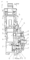
- the represented rotary hammer has a hammer housing 1, made up in the usual way of several components, which forms a gripping portion 3 at its rear end, so that a customary switch actuator 5 for switching the electric motor 6 on and off projects into a grip opening 4 which is defined at its rear side by the gripping portion 3.
- a mains lead which serves to connect the rotary hammer to a power source, is led out.
- an inner housing 1' Located in the upper portion of the rotary hammer in Figure 1 is an inner housing 1', formed of half-shells and made from cast aluminium or the like, which extends forwards out of the rotary hammer housing 1 and in which the hammer spindle 8 is rotatably housed.
- the rear end of the latter forms the guide tube 8', provided in known manner with vent apertures, for a pneumatic hammer mechanism, and at the front end of which the customary tool holder 2 is held.
- the hammer mechanism contains a piston 9 which is coupled, via a trunnion 11 housed in it and a crank arm 12, with a crank pin 15 which sits eccentrically on the upper plate-shaped end 14 of a drive shaft 13.
- a reciprocating movement of the piston 9 is carried out to alternately create a vacuum and an over-pressure in front of it, in order to move the ram 10 situated in the guide tube 8' correspondingly, so that this transmits impacts onto the beat piece 11, which passes them on to the rear end of a hammer bit or chisel bit, not represented, which is inserted into the tool holder 2.
- This mode of operation and the structure of a pneumatic hammer mechanism are, as already mentioned, known and will therefore not be explained in more detail.
- the electric motor 6 is arranged in the hammer housing 1 in such a way that its armature shaft 7 extends perpendicular to the longitudinal axis of the hammer spindle 8 and the tool holder 2, the longitudinal axis of the armature shaft 7 preferably lying in a plane with the longitudinal axis of the hammer spindle 8 and tool holder 2.
- a pinion 7' is formed which meshes with a gear wheel 18 which sits rotatable on the drive shaft 13 for the hammer mechanism.
- the pinion 7' also meshes with a gear wheel 21 which is arranged on the side of the armature shaft 7 lying opposite the drive shaft 13 and is non-rotatably secured on a shaft 22 rotatably housed in the housing 1'.
- a bevel gear is formed, which meshes with the bevel toothing 16' of a drive sleeve 16 which sits rotatable via a schematically indicated friction bearing, but axially non-displaceable on the hammer spindle 8 or on its rear part forming the guide tube 8' for the hammer mechanism.
- a coupling sleeve 17 is arranged, axially displaceable but non-rotatable as a result of engagement with a splined section on the outer surface of the hammer spindle 8, on the hammer spindle 8 in front of the drive sleeve 16.
- This coupling sleeve 17 can be displaced between a position in which it is in positive engagement, via teeth or projections formed at its rear end, with corresponding teeth or projections at the front end of the drive sleeve 17, and a forwardly displaced position in which there is no engagement between it and the drive sleeve 16.
- a helical spring 30' loads the coupling sleeve 17 in the direction of the drive sleeve 16.
- a rotation of the armature shaft 7 via the gear wheel 21 and the bevel toothing 23 of the shaft 22 causes a rotation of the drive sleeve 16 and, when there is a positive engagement between this and the coupling sleeve 17, also a rotation of the hammer spindle 8 and thus of the tool holder 2. Accordingly, in the absence of a positive engagement between the drive sleeve 16 and the coupling sleeve 17, the hammer spindle 8 is not rotated despite rotation of the drive sleeve 16.
- the gear wheel 18 driven by the pinion 7' of the armature shaft 7 is coupled with the drive shaft 13 in a manner yet to be described, so that the crank pin 15 performs a circular movement which creates, via the crank arm 12, the reciprocating movement of the piston 9 in the guide tube 8' of the hammer mechanism.
- This type of drive is also known in rotary hammers in which the armature shaft 7 of the drive motor 6 lies perpendicular to the longitudinal axis of the hammer spindle 8 and the tool holder 2.
- the latter has a single switching element 25 which is rotatable about its main axis 26. From the outside an actuation button, not represented, is secured to the switching element 25 and is accessible to the user. On its inside the switching element 25 has a cam section 27, which has a cam surface 28 which runs spirally around the main axis 26. It extends over an angle range of roughly 210 and the ends of the cam surface are connected by a rectilinear section. Projecting from the inner end of the switching element 25 is a rod- or pin-shaped actuating section 29 which extends parallel to the main axis 26 and at a lateral distance from the latter.
- a sleeve 19 sits on the drive shaft 13, non-rotatable through engagement with a splined section but axially displaceable, and has an annular flange 20 at its upper end in Figures 1 to 3.
- the sleeve 19 has projections or teeth, not represented, which, in the lower position of the sleeve 19 which is shown in Figures 2, 5, 7 and 9, are in positive engagement with corresponding recesses in the body of the gear wheel 18, so that in this position a rotation of the gear wheel 18 also brings about rotation of the drive shaft 13 which is in positive engagement with the sleeve 19.
- the rod- or pin-shaped actuating section 29 which is provided at the switching element 25 extends into the area below the flange 20 of the sleeve 19 and, upon rotation of the switching element 25 about its main axis 26, in the positions according to Figures 5, 7 and 9, is moved about same on a semi-circle which, when the sleeve 19 is situated in the lower position, lies below the flange 20. In all these positions, the sleeve 19 is therefore in positive engagement with the gear wheel 18, so that, upon rotation of the armature shaft 7, the hammer mechanism is driven as a result of the circular movement of the crank pin 15.
- connection section 30 which consists of a connection section 30 and an engagement section 35, which are guided in projections of the housing 1 which are not shown.
- connection section 30 has an bent part 31 which, as represented, supports itself against the cam surface 28 of the cam section 27 of the switching element 25.
- a spring 41 Supporting itself against the opposite bent end 32 is one end of a spring 41 which sits on a pin of the engagement section 35 and, with its other end, rests against a side wall of the engagement section 35.
- This spring is stiffer than the spring 30' acting on the coupling sleeve 17 and thus creates, between connection section 30 and engagement section 35, a force which loads the connection section 30 in the direction of engagement with the cam surface 28 and the engagement section 35 in the forward direction, i.e. in the direction of the front end of the spindle 8, if the sections 30, 35 are displaced relative to each other.
- legs extending on both sides of the hammer spindle 8, of which only the leg 37 is represented in the drawings are formed at lateral projections 36, 38, so that the engagement section 35 has an essentially U-shaped cross-section in this area.
- the legs 37 extend upwards from the essentially level engagement section 35 above the level of the longitudinal axis of the hammer spindle 8, as is shown in Figures 2, 3, 5, 7 and 9.
- a rotation of the switching element 25 causes, in addition to the movement explained above of the rod- or pin-shaped actuating section 9, a displacement of the slider part 30, 35 as a result of the changing distance of the cam surface 28 from the main axis 26 of the switching element 25.
- the bent part 38 of the connection section 30 lies against a zone of the cam surface 28 which is at a minimum distance from the main axis 26, whereby the coupling sleeve 17 is pressed, as a result of the action of the spring 30, into positive engagement with the drive sleeve 16, and the hammer spindle 8 is driven rotatingly upon rotation of the armature shaft 7. Since, in this operating mode, the rod- or pin-shaped actuating section 29 has raised the sleeve 28 out of positive engagement with the gear wheel 18 and therefore the hammer mechanism is not driven, this is the operating mode for pure drilling.
- the drive remains activated for the hammer mech-anism, but there is a forward displacement of the bent part 31 and thus of the slider part 30, 35.
- the legs 37 of the engage-ment section 35 rest against the rear surfaces of the teeth or projections protruding radially outwards at the front end of the coupling sleeve 17 and thereby displace this coupling sleeve into a position in which it is not engaged with the drive sleeve 16, so that the drive for the rotation of the hammer spindle 8 is broken.
- the hammer spindle 8 is not yet secured against non-driven rotation.
- the rotary hammer is in the operating mode for hammering or chiselling.
- the coupling sleeve 17 is loaded by action of the spring 41 in forward direction in such a way that, when there is a relative twisting of the coupling sleeve 17 and the housing-fixed zone 24, a positive engagement comes about between them if it was not possible to create this positive engagement at first, because the end faces of the projections or teeth of the coupling sleeve 17 come to rest against the end faces lying between the recesses in the housing-fixed zone 24.
Abstract
Description
- The invention relates to a rotary hammer with a hammer housing, an electric motor provided in the hammer housing, a tool holder which is provided at the front end of the hammer housing and which can be rotatingly driven by the electric motor about the spindle axis of the hammer spindle, a hammer mechanism provided in the hammer housing for generating impacts acting on the rear end of a hammer bit or chisel bit inserted into the tool holder, and a switching element which is rotatable from the outside about its main axis and which has a cam section for switching between at least three operating modes, of which the first is pure drilling, the second hammer drilling and the third chiselling.
- Known rotary hammers of this type (German
Patent Application P 40 13 512) with switching between more than two operating modes by means of a single switching element are known. In these, there is a parallel arrangement of the axis of the hammer spindle, of the armature shaft of the electric motor and of the intermediate shaft which is driven by this and, in the activated case, drives the hammer mechanism and brings about the rotation of the tool holder. All the coupling and uncoupling processes for the activation and deactivation of the rotary drive and of the hammer mechanism therefore take place in one direction, namely parallel to the axis of the hammer spindle, so that the operating mode in question can be set by successive actuation of different coupling arrangements. - In the case of larger rotary hammers in which the drive motor is arranged with its armature shaft at right angles to the axis of the hammer spindle, it is not at present possible to carry out switching between more than two operating modes. i.e. in addition to switching between activated and deactivated rotary drive or to switching between activated and deactivated hammer mechanism, with a single switching element. Rather, separate switching elements are used, one of which moves the coupling arrangement for the rotary drive in a direction parallel to the axis of the hammer spindle, this parallel movement generally being directed coaxially relative to the axis of the hammer spindle, while the other switching element displaces the coupling arrangement for the activation and deactivation of the hammer mechanism parallel or coaxially relative to the armature shaft.
- The object of the invention is to simplify the structure of a rotary hammer in which the armature shaft of the electric motor is arranged perpendicular to the axis of the rotary hammer spindle by making it possible for switching between at least three operating modes to be effected with a single switching element.
- To achieve this object, a rotary hammer of the type mentioned at the beginning, in which the armature shaft of the electric motor is arranged perpendicular to the axis of the hammer spindle and the armature shaft can selectively be coupled with a drive shaft for the hammer mechanism, is designed in such a way that the armature shaft drives a drive sleeve which is rotatably arranged on the hammer spindle and which can be coupled with the hammer spindle via a coupling sleeve which sits non-rotatable but axially displaceable on the hammer spindle, that the cam section of the switching element acts on the coupling sleeve via a slider part which can be moved parallel to the axis of the hammer spindle, so that the coupling sleeve can be moved between a position of engagement with the drive sleeve and a release position separated from the drive sleeve, and that an actuating section which is eccentric relative to the main axis and which cooperates with a coupling part which can be moved coaxially relative to the drive shaft, is provided at the switching element in order to move the coupling part between a position coupling the drive shaft with the armature shaft and a position in which the drive connection between the armature shaft and the drive shaft is broken.
- In the case of the rotary hammer according to the invention, the activation and deactivation of the rotary drive thus takes place by means of a slider part which is arranged between the coupling sleeve and the switching element, so that switching is made possible through action on the slider part at a distance from the actual coupling arrangement for the rotary drive, to which end the slider part can be displaced parallel to the axis of the hammer spindle by the cam section provided at the switching element. In this way, the movement of the coupling sleeve is brought about in the manner that is usual per se parallel or coaxially relative to the axis of the hammer spindle.
- The activation and deactivation of the rotary drive of a rotary hammer through displacement of a coupling sleeve sitting on the hammer spindle is customary in rotary hammers of the type concerned (U.S. Patent No. 4 236 588). However, the associated switching element is situated in the immediate vicinity of the coupling sleeve and engages with an eccentric pin or the like with an annular groove of the coupling sleeve, so that the latter is axially displaced upon rotation of the switching element.
- The activation and deactivation of the hammer mechanism of the rotary hammer according to the invention is achieved by the provision, at the switching element, of an actuating section lying eccentrically relative to its main axis, so that, upon rotation of the switching element arranged immediately adjacent to the coupling part of the drive shaft for the hammer mechanism, the coupling part can be moved between an engagement position, in which it couples the drive shaft for the hammer mechanism with the armature shaft of the electric motor, and a release position, in which the coupling of the armature shaft and the drive shaft is broken.
- In a withdrawn position, the coupling sleeve may be in positive engagement with the drive sleeve, and so rotatingly drive the latter and thus the hammer spindle and the tool holder in operation of the rotary hammer, whereas in an advanced position it can be in positive engagement with a housing-fixed zone, in order to thus secure the hammer spindle against rotation, so that in the chisel mode the chisel bit inserted into the tool holder is not rotated. The coupling sleeve is expediently spring-loaded in the direction of the withdrawn position, so that, in the event of a misalignment of the sections bringing about the positive engagement between the coupling sleeve and the drive sleeve, it automatically locks in the engagement position when there is a twisting of the coupling sleeve and the drive sleeve relative to each other.
- The cam section of the switching element may have a cam surface which runs eccentrically relative to the main axis of the switch-ing element and against which the rear end of the slider part rests, in order to thus displace the latter, upon rotation of the switching element, parallel to the axis of the hammer spindle. The front end of the slider part is preferably fork-shaped and, in order to displace the coupling sleeve into its advanced posit-ion, engages with the fork arms with a support surface which is provided on the outer surface of the coupling sleeve, the result being a loading of the coupling sleeve which is uniform on both sides and by means of which tipping movements can be avoided.
- The slider part may be spring-loaded in the direction of the advanced position of the coupling sleeve, in order, in the case of the misalignment of the engagement sections of the coupling sleeve and housing-fixed zone during the switching process, to then bring about an engagement at once when a twisting of the coupling sleeve occurs in relation to the housing-fixed zone.
- The coupling part serving for activation and deactivation of the hammer mechanism may be spring-loaded in the direction of the coupling with the drive shaft. It may consist of a sleeve which sits non-rotatable but axially displaceable on the drive shaft and which has a radially outwardly directed flange. In order to bring about a displacement of such a sleeve-shaped coupling part, the actuating section which is arranged eccentrically relative to the main axis of the switching element can be brought, by rotation of the switching element, into engagement with the flange which displaces the coupling part.
- The invention is explained in more detail below with reference to the drawings which show an embodiment.
- Figure 1 shows, partly broken open and in section, a rotary hammer.
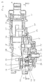
- Figure 2 shows, partly in section, partly as a view, a portion of the rotary hammer from Figure 1.
- Figure 3 shows, partly in section and partially as a view, the portion of the rotary hammer from Figures 1 and 2 around the hammer spindle in an operating position for pure drilling.
- Figure 4 shows a section along the line IV-IV from Figure 3, a part of the rotary hammer being represented as a view.
- Figure 5 shows, in a representation corresponding to Figure 3, the rotary hammer in the operating position for hammer drilling.
- Figure 6 shows, in a representation corresponding to Figure 4, a section along the line VI-VI from Figure 5.
- Figure 7 shows, in a representation corresponding to Figures 3 and 5, the rotary hammer in the chiselling position with the hammer spindle unlocked.
- Figure 8 shows a section along the line VIII-VIII from Figure 7 in a representation corresponding to Figures 4 and 6.
- Figure 9 shows, in a representation corresponding to Figures 3, 5 and 7, the rotary hammer in the chiselling position with the hammer spindle locked.
- Figure 10 shows a section along the line X-X from Figure 9 in a representation corresponding to Figures 4, 6 and 8.
-
- The represented rotary hammer has a
hammer housing 1, made up in the usual way of several components, which forms agripping portion 3 at its rear end, so that acustomary switch actuator 5 for switching theelectric motor 6 on and off projects into agrip opening 4 which is defined at its rear side by the grippingportion 3. In the rear lower portion of thehammer housing 1, a mains lead which serves to connect the rotary hammer to a power source, is led out. - Located in the upper portion of the rotary hammer in Figure 1 is an inner housing 1', formed of half-shells and made from cast aluminium or the like, which extends forwards out of the
rotary hammer housing 1 and in which thehammer spindle 8 is rotatably housed. The rear end of the latter forms the guide tube 8', provided in known manner with vent apertures, for a pneumatic hammer mechanism, and at the front end of which thecustomary tool holder 2 is held. The hammer mechanism contains apiston 9 which is coupled, via atrunnion 11 housed in it and acrank arm 12, with acrank pin 15 which sits eccentrically on the upper plate-shaped end 14 of adrive shaft 13. A reciprocating movement of thepiston 9 is carried out to alternately create a vacuum and an over-pressure in front of it, in order to move theram 10 situated in the guide tube 8' correspondingly, so that this transmits impacts onto thebeat piece 11, which passes them on to the rear end of a hammer bit or chisel bit, not represented, which is inserted into thetool holder 2. This mode of operation and the structure of a pneumatic hammer mechanism are, as already mentioned, known and will therefore not be explained in more detail. - The
electric motor 6 is arranged in thehammer housing 1 in such a way that itsarmature shaft 7 extends perpendicular to the longitudinal axis of thehammer spindle 8 and thetool holder 2, the longitudinal axis of thearmature shaft 7 preferably lying in a plane with the longitudinal axis of thehammer spindle 8 andtool holder 2. At the upper end of thearmature shaft 7 in Figure 1 a pinion 7' is formed which meshes with agear wheel 18 which sits rotatable on thedrive shaft 13 for the hammer mechanism. The pinion 7' also meshes with agear wheel 21 which is arranged on the side of thearmature shaft 7 lying opposite thedrive shaft 13 and is non-rotatably secured on ashaft 22 rotatably housed in the housing 1'. At the upper end of the shaft 22 a bevel gear is formed, which meshes with the bevel toothing 16' of adrive sleeve 16 which sits rotatable via a schematically indicated friction bearing, but axially non-displaceable on thehammer spindle 8 or on its rear part forming the guide tube 8' for the hammer mechanism. Acoupling sleeve 17 is arranged, axially displaceable but non-rotatable as a result of engagement with a splined section on the outer surface of thehammer spindle 8, on thehammer spindle 8 in front of thedrive sleeve 16. Thiscoupling sleeve 17 can be displaced between a position in which it is in positive engagement, via teeth or projections formed at its rear end, with corresponding teeth or projections at the front end of thedrive sleeve 17, and a forwardly displaced position in which there is no engagement between it and thedrive sleeve 16. A helical spring 30' loads thecoupling sleeve 17 in the direction of thedrive sleeve 16. The result of this spring loading is that, upon movement of thecoupling sleeve 17 in the direction of the positive engagement with thedrive sleeve 16 and a concomitant blocking of the positive engagement by abutment of the end faces of the projections or teeth of thecoupling sleeve 17 against the end face of the projections or teeth of thedrive sleeve 16, a positive engagement is then automatically established when there is a relative twisting of thecoupling sleeve 17 and thedrive sleeve 16, say because theshaft 22 rotates thedrive sleeve 16. - As is to be seen, a rotation of the
armature shaft 7 via thegear wheel 21 and the bevel toothing 23 of theshaft 22 causes a rotation of thedrive sleeve 16 and, when there is a positive engagement between this and thecoupling sleeve 17, also a rotation of thehammer spindle 8 and thus of thetool holder 2. Accordingly, in the absence of a positive engagement between thedrive sleeve 16 and thecoupling sleeve 17, thehammer spindle 8 is not rotated despite rotation of thedrive sleeve 16. If, rather, the coupling sleeve 17 with its protrusions which are provided at the front end-area and project radially outwards enter into a positive engagement with corresponding recesses in the housing-fixedzone 24, the result is a position of thecoupling sleeve 17, and thus of thehammer spindle 8 including thetool holder 2, which is locked against rotation. This mode of operation of thecoupling sleeve 17 is known. - To drive the hammer mechanism, the
gear wheel 18 driven by the pinion 7' of thearmature shaft 7 is coupled with thedrive shaft 13 in a manner yet to be described, so that thecrank pin 15 performs a circular movement which creates, via thecrank arm 12, the reciprocating movement of thepiston 9 in the guide tube 8' of the hammer mechanism. This type of drive is also known in rotary hammers in which thearmature shaft 7 of thedrive motor 6 lies perpendicular to the longitudinal axis of thehammer spindle 8 and thetool holder 2. - To switch between the individual operating modes of the rotary hammer, the latter has a
single switching element 25 which is rotatable about itsmain axis 26. From the outside an actuation button, not represented, is secured to theswitching element 25 and is accessible to the user. On its inside theswitching element 25 has acam section 27, which has acam surface 28 which runs spirally around themain axis 26. It extends over an angle range of roughly 210 and the ends of the cam surface are connected by a rectilinear section. Projecting from the inner end of theswitching element 25 is a rod- or pin-shaped actuating section 29 which extends parallel to themain axis 26 and at a lateral distance from the latter. - A
sleeve 19 sits on thedrive shaft 13, non-rotatable through engagement with a splined section but axially displaceable, and has anannular flange 20 at its upper end in Figures 1 to 3. Aspring 21, which lies with its upper end against the inner race of a ball bearing rotatably housing thedrive shaft 13, supports itself on theannular flange 20, so that a force which is directed downwards, i.e. in the direction of thegear wheel 18, acts permanently on thesleeve 19. At the lower end, thesleeve 19 has projections or teeth, not represented, which, in the lower position of thesleeve 19 which is shown in Figures 2, 5, 7 and 9, are in positive engagement with corresponding recesses in the body of thegear wheel 18, so that in this position a rotation of thegear wheel 18 also brings about rotation of thedrive shaft 13 which is in positive engagement with thesleeve 19. - The rod- or pin-
shaped actuating section 29 which is provided at the switchingelement 25 extends into the area below theflange 20 of thesleeve 19 and, upon rotation of theswitching element 25 about itsmain axis 26, in the positions according to Figures 5, 7 and 9, is moved about same on a semi-circle which, when thesleeve 19 is situated in the lower position, lies below theflange 20. In all these positions, thesleeve 19 is therefore in positive engagement with thegear wheel 18, so that, upon rotation of thearmature shaft 7, the hammer mechanism is driven as a result of the circular movement of thecrank pin 15. How-ever, if theswitching element 25 is twisted clockwise out of the position according to Figure 5 or counter-clockwise out of the position according to Figure 9, the result is an engagement of the rod- or pin-shaped actuating section 29 with the lower surface of theflange 20 and thereby a raising of thesleeve 19, against the force of thespring 21 acting on it, out of the engagement position with thegear wheel 18. In this position, shown in Figure 3, the hammer mechanism is not driven when thegear wheel 18 is driven, i.e. the rotary hammer operates in pure drilling mode. To change the aforementioned position of thecoupling sleeve 17 which is arranged non-rotatable, but axially displaceable on thehammer spindle 8, a slider part is provided which consists of aconnection section 30 and anengagement section 35, which are guided in projections of thehousing 1 which are not shown. At one end, theconnection section 30 has anbent part 31 which, as represented, supports itself against thecam surface 28 of thecam section 27 of the switchingelement 25. Supporting itself against the oppositebent end 32 is one end of aspring 41 which sits on a pin of theengagement section 35 and, with its other end, rests against a side wall of theengagement section 35. This spring is stiffer than the spring 30' acting on thecoupling sleeve 17 and thus creates, betweenconnection section 30 andengagement section 35, a force which loads theconnection section 30 in the direction of engagement with thecam surface 28 and theengagement section 35 in the forward direction, i.e. in the direction of the front end of thespindle 8, if thesections engagement section 35, legs extending on both sides of thehammer spindle 8, of which only theleg 37 is represented in the drawings, are formed atlateral projections engagement section 35 has an essentially U-shaped cross-section in this area. Thelegs 37 extend upwards from the essentiallylevel engagement section 35 above the level of the longitudinal axis of thehammer spindle 8, as is shown in Figures 2, 3, 5, 7 and 9. - As is to be seen at once, a rotation of the switching
element 25 causes, in addition to the movement explained above of the rod- or pin-shapedactuating section 9, a displacement of theslider part cam surface 28 from themain axis 26 of the switchingelement 25. If the operating mode according to Figures 3 and 4 is considered first, it will be seen that thebent part 38 of theconnection section 30 lies against a zone of thecam surface 28 which is at a minimum distance from themain axis 26, whereby thecoupling sleeve 17 is pressed, as a result of the action of thespring 30, into positive engagement with thedrive sleeve 16, and thehammer spindle 8 is driven rotatingly upon rotation of thearmature shaft 7. Since, in this operating mode, the rod- or pin-shapedactuating section 29 has raised thesleeve 28 out of positive engagement with thegear wheel 18 and therefore the hammer mechanism is not driven, this is the operating mode for pure drilling. - If the switching
element 25 is twisted clockwise out of the position according to Figure 3 into the position according to Figure 5, the result, as already described, is a lowering of thesleeve 19 into positive engagement with thegear wheel 18 and therefore in a position for driving of the hammer mechanism, whereas, because thecam surface 28 is not changing its distance from themain axis 26, the position of thebent part 31 and thus of theslider part hammer spindle 8 is rotated, so that the operating mode for rotary hammering is set. - If the switching
element 25 is rotated further clockwise out of the position according to Figure 5 into the position according to Figure 7, the drive remains activated for the hammer mech-anism, but there is a forward displacement of thebent part 31 and thus of theslider part legs 37 of the engage-ment section 35 rest against the rear surfaces of the teeth or projections protruding radially outwards at the front end of thecoupling sleeve 17 and thereby displace this coupling sleeve into a position in which it is not engaged with thedrive sleeve 16, so that the drive for the rotation of thehammer spindle 8 is broken. However, since there is still no positive engagement between the recesses in the housing-fixedzone 24 and the pro-jections or teeth at the front end of thecoupling sleeve 17, thehammer spindle 8 is not yet secured against non-driven rotation. The rotary hammer is in the operating mode for hammering or chiselling. - Further rotation of the switching
element 25 clockwise out of the position according to Figure 7 into the position according to Figure 9 does not bring about a change in the position of thesleeve 19, so that the hammer mechanism remains activated. How-ever, since the radial distance of thecam surface 28 of thecam element 27 from the switchingelement 25 increases further, theslider part coupling sleeve 17, so that the teeth or projections protruding radially outwards at its front end enter into positive engagement with the corresponding recesses in the housing-fixedzone 24, and so thehammer spindle 8 is locked against rotation. It should be mentioned that thecoupling sleeve 17 is loaded by action of thespring 41 in forward direction in such a way that, when there is a relative twisting of thecoupling sleeve 17 and the housing-fixedzone 24, a positive engagement comes about between them if it was not possible to create this positive engagement at first, because the end faces of the projections or teeth of thecoupling sleeve 17 come to rest against the end faces lying between the recesses in the housing-fixedzone 24.
Claims (6)
- Rotary hammer witha hammer housing (1),a tool holder (2) which is provided at the front end of the hammer housing (1) and which can be rotatingly driven by the electric motor (6) about the axis of the hammer spindle (8),a hammer mechanism which is provided in the hammer housing (1) for generating impacts acting on the rear end of a hammer bit or chisel bit inserted into the tool holder (2) anda switching element (25) which is rotatable from the outside about its main axis (26) and which has a cam section (27), for switching between at least three operating modes, of which the first is pure drilling, the second hammer drilling and the third chiselling,
characterised inthat the armature shaft (7) of the electric motor (6) is arranged perpendicular to the axis of the hammer spindle (8),that the armature shaft (7) can selectively be coupled with a drive shaft (13) for the hammer mechanism,that the armature shaft (7) drives a drive sleeve (16) which is arranged rotatable on the hammer spindle (8) and which can be coupled with the hammer spindle (8) via a coupling sleeve (17) which sits non-rotatable but axially displaceable on the hammer spindle (8),that the cam section (27) of the switching element (25) acts on the coupling sleeve (17) via a slider part (30, 35) which can be moved parallel to the axis of the hammer spindle (8), so that the coupling sleeve (17) can be moved between a position of engagement with the drive sleeve (16) and a release position separated from the drive sleeve (16), andthat there is provided at the switching element (25) an actuating section (29) which is eccentric relative to the main axis (26) and which cooperates with a coupling part (19) which can be moved coaxially relative to the drive shaft (13), in order to move the coupling part (19) between a position coupling the drive shaft (13) with the armature shaft (7) and a position in which the drive connection between the armature shaft (7) and the drive shaft (13) is broken. - Rotary hammer according to claim 1, characterised in that, in a withdrawn position, the coupling sleeve (17) is in positive engagement with the drive sleeve (16) and, in an advanced position, is in positive engagement with a housing-fixed zone (24), and that the coupling sleeve (17) is spring-loaded in the direction of the withdrawn position.
- Rotary hammer according to claim 2, characterised in that the slider part (30, 35) is spring-loaded in the direction of the advanced position of the coupling sleeve (17).
- Rotary hammer according to one of claims 1 to 3, characterised in that the cam section (27) has a cam surface (28) which runs spirally around the main axis (26) of the switching element (25) and against which the rear end (31) of the slider part (30, 35) rests, and that the front end of the slider part (30, 35) is fork-shaped and, in order to displace the coupling sleeve (17) into its advanced position, engages with its fork arms (37) with a support surface provided on the outer surface of the coupling sleeve (17).
- Rotary hammer according to one of claims 1 to 4, characterised in that the coupling part (19) is spring-loaded in the direction of the coupling with the drive shaft (13).
- Rotary hammer according to one of claims 1 to 5, characterised in that the coupling part consists of a sleeve (19) which sits non-rotatable but axially displace-able on the drive shaft (13) and has a radially outwardly directed flange (20), and that the actuating section (29) of the switching element (25) can be brought into engagement with the flange (20) which displaces the sleeve-shaped coupling part (19).
Applications Claiming Priority (3)
| Application Number | Priority Date | Filing Date | Title |
|---|---|---|---|
| DE19717712A DE19717712A1 (en) | 1997-04-18 | 1997-04-18 | Hammer drill |
| DE19717712 | 1997-04-18 | ||
| PCT/IB1998/000471 WO1998047670A1 (en) | 1997-04-18 | 1998-03-31 | Rotary hammer |
Publications (2)
| Publication Number | Publication Date |
|---|---|
| EP0975454A1 EP0975454A1 (en) | 2000-02-02 |
| EP0975454B1 true EP0975454B1 (en) | 2002-01-16 |
Family
ID=7827859
Family Applications (1)
| Application Number | Title | Priority Date | Filing Date |
|---|---|---|---|
| EP98908250A Expired - Lifetime EP0975454B1 (en) | 1997-04-18 | 1998-03-31 | Rotary hammer |
Country Status (6)
| Country | Link |
|---|---|
| US (1) | US6015017A (en) |
| EP (1) | EP0975454B1 (en) |
| AT (1) | ATE211959T1 (en) |
| AU (1) | AU6632798A (en) |
| DE (2) | DE19717712A1 (en) |
| WO (1) | WO1998047670A1 (en) |
Cited By (1)
| Publication number | Priority date | Publication date | Assignee | Title |
|---|---|---|---|---|
| CN101022925B (en) * | 2004-09-17 | 2010-09-29 | 罗伯特·博世有限公司 | Switching device |
Families Citing this family (52)
| Publication number | Priority date | Publication date | Assignee | Title |
|---|---|---|---|---|
| DE19937767B4 (en) * | 1999-08-10 | 2004-09-09 | Hilti Ag | Hand-held electric combi hammer |
| DE19942156A1 (en) * | 1999-09-03 | 2001-03-08 | Hilti Ag | Switching device for multifunctional hand-held machine tools |
| GB0008465D0 (en) * | 2000-04-07 | 2000-05-24 | Black & Decker Inc | Rotary hammer mode change mechanism |
| DE10029728A1 (en) * | 2000-06-16 | 2001-12-20 | Hilti Ag | Hand tool |
| JP4281273B2 (en) * | 2000-10-20 | 2009-06-17 | 日立工機株式会社 | Hammer drill |
| DE10151699B4 (en) * | 2000-10-20 | 2005-06-30 | Hitachi Koki Co., Ltd. | Hammer drill has switching lever to selectively engage and disengage pair of switching elements with a pair of gears, respectively |
| DE10164906B4 (en) * | 2000-10-20 | 2006-05-04 | Hitachi Koki Co., Ltd. | Hammer drill has switching lever to selectively engage and disengage pair of switching elements with a pair of gears, respectively |
| DE10057139A1 (en) * | 2000-11-17 | 2002-05-23 | Hilti Ag | Electric hand tool with safety clutch |
| GB0100605D0 (en) * | 2001-01-10 | 2001-02-21 | Black & Decker Inc | Hammer |
| DE10111746A1 (en) * | 2001-03-12 | 2002-09-19 | Hilti Ag | Shift transmission means for the combined shifting of a transmission |
| WO2003024671A2 (en) * | 2001-09-17 | 2003-03-27 | Milwaukee Electric Tool Corporation | Rotary hammer |
| DE10225239A1 (en) | 2002-06-06 | 2003-12-18 | Hilti Ag | Mode selector switch for combined electric hand machine tool |
| GB0213289D0 (en) * | 2002-06-11 | 2002-07-24 | Black & Decker Inc | Rotary hammer |
| US20050199407A1 (en) * | 2002-09-04 | 2005-09-15 | Aesculap Ag & Co. Kg | Surgical instrument |
| WO2004024398A1 (en) * | 2002-09-13 | 2004-03-25 | Black & Decker Inc | Rotary tool |
| GB2394517A (en) * | 2002-10-23 | 2004-04-28 | Black & Decker Inc | Powered hammer having a spindle lock with synchronising element |
| DE602004027011D1 (en) * | 2003-03-21 | 2010-06-17 | Black & Decker Inc | Uziervorrichtung |
| DE10312981A1 (en) * | 2003-03-24 | 2004-10-07 | Robert Bosch Gmbh | Electric hand tool |
| JP4291173B2 (en) * | 2004-02-10 | 2009-07-08 | 株式会社マキタ | Impact driver |
| JP4405900B2 (en) * | 2004-03-10 | 2010-01-27 | 株式会社マキタ | Impact driver |
| JP4515181B2 (en) * | 2004-07-20 | 2010-07-28 | 株式会社マキタ | Electric hammer drill |
| US7308948B2 (en) | 2004-10-28 | 2007-12-18 | Makita Corporation | Electric power tool |
| TWI279298B (en) * | 2004-11-24 | 2007-04-21 | Hitachi Koki Kk | Hammer drill |
| DE102004057686A1 (en) * | 2004-11-30 | 2006-06-01 | Robert Bosch Gmbh | switching device |
| EP1674206A1 (en) * | 2004-12-23 | 2006-06-28 | BLACK & DECKER INC. | Hammer mechanism for power tool |
| EP1674207B1 (en) | 2004-12-23 | 2008-12-10 | BLACK & DECKER INC. | Power tool |
| EP1674743B1 (en) * | 2004-12-23 | 2014-01-22 | Black & Decker Inc. | Drive mechanism for a power tool |
| GB2423048A (en) * | 2005-02-10 | 2006-08-16 | Black & Decker Inc | Hammer with two reciprocating strikers |
| GB2423046A (en) * | 2005-02-10 | 2006-08-16 | Black & Decker Inc | Hammer with cam mechanism and barrel surrounded by sleeve |
| GB2423047A (en) * | 2005-02-10 | 2006-08-16 | Black & Decker Inc | Hammer with rotating striker |
| DE102005041448A1 (en) * | 2005-08-31 | 2007-03-01 | Robert Bosch Gmbh | Hammer drill, comprises manually operated switch with outer shell and sealing ring |
| JP4812471B2 (en) * | 2006-03-09 | 2011-11-09 | 株式会社マキタ | Work tools |
| US8100928B2 (en) * | 2006-08-10 | 2012-01-24 | Ethicon, Inc. | Morcellator with detachable handle |
| GB0713432D0 (en) * | 2007-07-11 | 2007-08-22 | Black & Decker Inc | Rotary hammer-chain drive |
| US7717192B2 (en) | 2007-11-21 | 2010-05-18 | Black & Decker Inc. | Multi-mode drill with mode collar |
| US7798245B2 (en) | 2007-11-21 | 2010-09-21 | Black & Decker Inc. | Multi-mode drill with an electronic switching arrangement |
| US7770660B2 (en) | 2007-11-21 | 2010-08-10 | Black & Decker Inc. | Mid-handle drill construction and assembly process |
| US7735575B2 (en) | 2007-11-21 | 2010-06-15 | Black & Decker Inc. | Hammer drill with hard hammer support structure |
| US7762349B2 (en) * | 2007-11-21 | 2010-07-27 | Black & Decker Inc. | Multi-speed drill and transmission with low gear only clutch |
| US7854274B2 (en) * | 2007-11-21 | 2010-12-21 | Black & Decker Inc. | Multi-mode drill and transmission sub-assembly including a gear case cover supporting biasing |
| US7717191B2 (en) * | 2007-11-21 | 2010-05-18 | Black & Decker Inc. | Multi-mode hammer drill with shift lock |
| GB0912283D0 (en) | 2009-07-15 | 2009-08-26 | Black & Decker Inc | Motor driven hammer having means for controlling the power of impact |
| US8087472B2 (en) * | 2009-07-31 | 2012-01-03 | Black & Decker Inc. | Vibration dampening system for a power tool and in particular for a powered hammer |
| DE102012209446A1 (en) * | 2012-06-05 | 2013-12-05 | Robert Bosch Gmbh | Hand machine tool device |
| US9630307B2 (en) | 2012-08-22 | 2017-04-25 | Milwaukee Electric Tool Corporation | Rotary hammer |
| JP2014100762A (en) * | 2012-11-19 | 2014-06-05 | Makita Corp | Impact tool |
| GB201321893D0 (en) | 2013-12-11 | 2014-01-22 | Black & Decker Inc | Rotary Hammer |
| CN104786199B (en) * | 2014-11-07 | 2016-06-29 | 江苏东成机电工具有限公司 | A kind of mode-changeover device |
| DE102017209829A1 (en) * | 2017-06-12 | 2018-12-13 | Robert Bosch Gmbh | Hand tool |
| US11529727B2 (en) | 2019-10-21 | 2022-12-20 | Makita Corporation | Power tool having hammer mechanism |
| US11642769B2 (en) * | 2021-02-22 | 2023-05-09 | Makita Corporation | Power tool having a hammer mechanism |
| CN115056362B (en) * | 2022-07-05 | 2022-12-13 | 永康市灵威电器有限公司 | Electric tool accessory and lithium electric tool |
Family Cites Families (29)
| Publication number | Priority date | Publication date | Assignee | Title |
|---|---|---|---|---|
| US33733A (en) * | 1861-11-19 | Improvement in machinery for bending hooks and staples | ||
| SE353262B (en) * | 1971-02-02 | 1973-01-29 | Volume Pac Ab | |
| DE2136523C3 (en) * | 1971-07-21 | 1983-11-03 | Hilti AG, 9494 Schaan | Electric hammer |
| CH534036A (en) * | 1972-04-18 | 1973-02-28 | Rudolf Studer Fabrik Elek Sche | Motor-driven hammer drill, in particular by an electric motor |
| DE2242944B2 (en) * | 1972-08-31 | 1981-04-23 | Robert Bosch Gmbh, 7000 Stuttgart | Hammer drill |
| DE2252951B2 (en) * | 1972-10-28 | 1981-09-10 | Robert Bosch Gmbh, 7000 Stuttgart | Hammer drill |
| US3837409A (en) * | 1973-02-26 | 1974-09-24 | Skil Corp | Rotary hammer power tool |
| DE2728961C2 (en) * | 1977-06-27 | 1991-08-08 | Hilti Ag, Schaan | Rotary hammer with lockable tool holder |
| DE2820128A1 (en) * | 1978-05-09 | 1979-11-22 | Bosch Gmbh Robert | CRAFT MACHINE |
| DE2920065C2 (en) * | 1979-05-18 | 1986-07-17 | Metabowerke GmbH & Co, 7440 Nürtingen | Motor-driven hand machine tool for drilling, hammer drilling and screwdriving |
| ZA803409B (en) * | 1979-06-18 | 1981-05-27 | Kango Electric Hammers Ltd | Hammer drill |
| US4346767A (en) * | 1980-06-11 | 1982-08-31 | Kango Electric Hammers Limited | Rotary impact drill |
| DE3310145C2 (en) * | 1983-03-21 | 1993-10-21 | Hilti Ag | Electropneumatic hammer drill with replaceable hammer mechanism |
| DE3311265A1 (en) * | 1983-03-28 | 1984-10-11 | Hilti Ag, Schaan | ELECTROPNEUMATIC DRILL AND CHISEL HAMMER |
| DE3538166A1 (en) * | 1985-10-26 | 1987-04-30 | Hilti Ag | DRILL HAMMER WITH TURN LOCK |
| DE3623648A1 (en) * | 1986-07-12 | 1988-01-14 | Hilti Ag | Hammer drill with percussive mechanism |
| NL8801466A (en) * | 1988-06-07 | 1990-01-02 | Emerson Electric Co | DEVICE FOR DRIVING A DRILL AND / OR IMPACT TOOL. |
| DE3931329C1 (en) * | 1989-05-31 | 1990-06-28 | Robert Bosch Gmbh, 7000 Stuttgart, De | |
| DE4013512A1 (en) * | 1990-04-27 | 1991-10-31 | Black & Decker Inc | SWITCHING DEVICE FOR SWITCHING A POWERED TOOL |
| DE4215288A1 (en) * | 1991-07-08 | 1993-01-14 | Bosch Gmbh Robert | DRILLING HAMMER |
| DE4135240A1 (en) * | 1991-10-25 | 1993-04-29 | Bosch Gmbh Robert | DRILLING HAMMER |
| DE4136236C2 (en) * | 1991-11-02 | 1995-02-23 | Heidelberger Druckmasch Ag | Alignment monitoring device on rotary printing presses |
| DE4202767C2 (en) * | 1992-01-31 | 1999-06-02 | Black & Decker Inc | Hammer drill |
| US5320177A (en) * | 1992-03-30 | 1994-06-14 | Makita Corporation | Power driven hammer drill |
| US5346023A (en) * | 1993-02-11 | 1994-09-13 | Hitachi Koki Company Limited | Slipping torque changing apparatus for impact tool |
| JP2602411Y2 (en) * | 1993-11-26 | 2000-01-17 | 日立工機株式会社 | Switching mechanism of impact tool |
| DE4343583B4 (en) * | 1993-12-21 | 2005-03-24 | Robert Bosch Gmbh | Rotary Hammer |
| JP3292969B2 (en) * | 1995-08-18 | 2002-06-17 | 株式会社マキタ | Hammer drill |
| JP3424880B2 (en) * | 1995-08-18 | 2003-07-07 | 株式会社マキタ | Hammer drill |
-
1997
- 1997-04-18 DE DE19717712A patent/DE19717712A1/en not_active Withdrawn
-
1998
- 1998-03-31 AU AU66327/98A patent/AU6632798A/en not_active Abandoned
- 1998-03-31 AT AT98908250T patent/ATE211959T1/en not_active IP Right Cessation
- 1998-03-31 EP EP98908250A patent/EP0975454B1/en not_active Expired - Lifetime
- 1998-03-31 DE DE69803174T patent/DE69803174T2/en not_active Expired - Lifetime
- 1998-03-31 WO PCT/IB1998/000471 patent/WO1998047670A1/en active IP Right Grant
- 1998-04-15 US US09/060,395 patent/US6015017A/en not_active Expired - Lifetime
Cited By (1)
| Publication number | Priority date | Publication date | Assignee | Title |
|---|---|---|---|---|
| CN101022925B (en) * | 2004-09-17 | 2010-09-29 | 罗伯特·博世有限公司 | Switching device |
Also Published As
| Publication number | Publication date |
|---|---|
| DE69803174T2 (en) | 2002-07-25 |
| EP0975454A1 (en) | 2000-02-02 |
| AU6632798A (en) | 1998-11-13 |
| WO1998047670A1 (en) | 1998-10-29 |
| DE19717712A1 (en) | 1998-10-22 |
| US6015017A (en) | 2000-01-18 |
| ATE211959T1 (en) | 2002-02-15 |
| DE69803174D1 (en) | 2002-02-21 |
Similar Documents
| Publication | Publication Date | Title |
|---|---|---|
| EP0975454B1 (en) | Rotary hammer | |
| EP0775555B1 (en) | Rotary hammer | |
| US7497272B2 (en) | Hand-held power tool | |
| US5379848A (en) | Drill hammer | |
| US6510903B2 (en) | Combination electrical hand-held tool | |
| US4446931A (en) | Power driven hammer drill | |
| EP1413402B1 (en) | Hammer | |
| US7121359B2 (en) | Drilling hammer having an external mechanism for selectively switching operation between impact drilling and chiseling modes | |
| EP1477280B1 (en) | Rotary hammer | |
| EP0454348B1 (en) | Power tool | |
| EP1832393B1 (en) | Power tool | |
| EP1293303B1 (en) | Tool holder for hammer | |
| US20060065416A1 (en) | Hammer | |
| EP3034243B1 (en) | Rotary hammer | |
| JP2003501276A (en) | Spindle lock and chipping mechanism of hammer drill | |
| EP1223010B1 (en) | Percussion hammer | |
| EP0608083B1 (en) | Power driven tool, in particular an electric tool | |
| GB2314288A (en) | Electric combination hammer | |
| EP2883661B1 (en) | Rotary hammer | |
| GB2085795A (en) | A hammer drill | |
| GB2371009A (en) | Hand-held machine tool | |
| AU640541B2 (en) | Drilling and chiselling device | |
| GB2324491A (en) | Hammer drill with clutch mechanism | |
| CN117644226A (en) | Hammer drill |
Legal Events
| Date | Code | Title | Description |
|---|---|---|---|
| PUAI | Public reference made under article 153(3) epc to a published international application that has entered the european phase |
Free format text: ORIGINAL CODE: 0009012 |
|
| 17P | Request for examination filed |
Effective date: 19990529 |
|
| AK | Designated contracting states |
Kind code of ref document: A1 Designated state(s): AT BE CH DE ES FI FR GB IT LI NL SE |
|
| GRAG | Despatch of communication of intention to grant |
Free format text: ORIGINAL CODE: EPIDOS AGRA |
|
| 17Q | First examination report despatched |
Effective date: 20010328 |
|
| GRAG | Despatch of communication of intention to grant |
Free format text: ORIGINAL CODE: EPIDOS AGRA |
|
| GRAH | Despatch of communication of intention to grant a patent |
Free format text: ORIGINAL CODE: EPIDOS IGRA |
|
| GRAH | Despatch of communication of intention to grant a patent |
Free format text: ORIGINAL CODE: EPIDOS IGRA |
|
| GRAA | (expected) grant |
Free format text: ORIGINAL CODE: 0009210 |
|
| REG | Reference to a national code |
Ref country code: GB Ref legal event code: IF02 |
|
| AK | Designated contracting states |
Kind code of ref document: B1 Designated state(s): AT BE CH DE ES FI FR GB IT LI NL SE |
|
| PG25 | Lapsed in a contracting state [announced via postgrant information from national office to epo] |
Ref country code: NL Free format text: LAPSE BECAUSE OF FAILURE TO SUBMIT A TRANSLATION OF THE DESCRIPTION OR TO PAY THE FEE WITHIN THE PRESCRIBED TIME-LIMIT Effective date: 20020116 Ref country code: IT Free format text: LAPSE BECAUSE OF FAILURE TO SUBMIT A TRANSLATION OF THE DESCRIPTION OR TO PAY THE FEE WITHIN THE PRESCRIBED TIME-LIMIT;WARNING: LAPSES OF ITALIAN PATENTS WITH EFFECTIVE DATE BEFORE 2007 MAY HAVE OCCURRED AT ANY TIME BEFORE 2007. THE CORRECT EFFECTIVE DATE MAY BE DIFFERENT FROM THE ONE RECORDED. Effective date: 20020116 Ref country code: FI Free format text: LAPSE BECAUSE OF FAILURE TO SUBMIT A TRANSLATION OF THE DESCRIPTION OR TO PAY THE FEE WITHIN THE PRESCRIBED TIME-LIMIT Effective date: 20020116 Ref country code: BE Free format text: LAPSE BECAUSE OF FAILURE TO SUBMIT A TRANSLATION OF THE DESCRIPTION OR TO PAY THE FEE WITHIN THE PRESCRIBED TIME-LIMIT Effective date: 20020116 Ref country code: AT Free format text: LAPSE BECAUSE OF FAILURE TO SUBMIT A TRANSLATION OF THE DESCRIPTION OR TO PAY THE FEE WITHIN THE PRESCRIBED TIME-LIMIT Effective date: 20020116 |
|
| REF | Corresponds to: |
Ref document number: 211959 Country of ref document: AT Date of ref document: 20020215 Kind code of ref document: T |
|
| REG | Reference to a national code |
Ref country code: CH Ref legal event code: EP |
|
| REF | Corresponds to: |
Ref document number: 69803174 Country of ref document: DE Date of ref document: 20020221 |
|
| REG | Reference to a national code |
Ref country code: CH Ref legal event code: NV Representative=s name: PATENTANWALTSBUREAU R. A. MASPOLI |
|
| PGFP | Annual fee paid to national office [announced via postgrant information from national office to epo] |
Ref country code: SE Payment date: 20020305 Year of fee payment: 5 Ref country code: NL Payment date: 20020305 Year of fee payment: 5 Ref country code: AT Payment date: 20020305 Year of fee payment: 5 |
|
| PGFP | Annual fee paid to national office [announced via postgrant information from national office to epo] |
Ref country code: FI Payment date: 20020306 Year of fee payment: 5 |
|
| PGFP | Annual fee paid to national office [announced via postgrant information from national office to epo] |
Ref country code: BE Payment date: 20020327 Year of fee payment: 5 |
|
| PGFP | Annual fee paid to national office [announced via postgrant information from national office to epo] |
Ref country code: ES Payment date: 20020409 Year of fee payment: 5 |
|
| PG25 | Lapsed in a contracting state [announced via postgrant information from national office to epo] |
Ref country code: SE Free format text: LAPSE BECAUSE OF FAILURE TO SUBMIT A TRANSLATION OF THE DESCRIPTION OR TO PAY THE FEE WITHIN THE PRESCRIBED TIME-LIMIT Effective date: 20020416 |
|
| ET | Fr: translation filed | ||
| NLV1 | Nl: lapsed or annulled due to failure to fulfill the requirements of art. 29p and 29m of the patents act | ||
| PG25 | Lapsed in a contracting state [announced via postgrant information from national office to epo] |
Ref country code: ES Free format text: LAPSE BECAUSE OF FAILURE TO SUBMIT A TRANSLATION OF THE DESCRIPTION OR TO PAY THE FEE WITHIN THE PRESCRIBED TIME-LIMIT Effective date: 20020730 |
|
| PLBE | No opposition filed within time limit |
Free format text: ORIGINAL CODE: 0009261 |
|
| STAA | Information on the status of an ep patent application or granted ep patent |
Free format text: STATUS: NO OPPOSITION FILED WITHIN TIME LIMIT |
|
| 26N | No opposition filed | ||
| PGFP | Annual fee paid to national office [announced via postgrant information from national office to epo] |
Ref country code: CH Payment date: 20110325 Year of fee payment: 14 |
|
| PGFP | Annual fee paid to national office [announced via postgrant information from national office to epo] |
Ref country code: FR Payment date: 20120406 Year of fee payment: 15 |
|
| REG | Reference to a national code |
Ref country code: CH Ref legal event code: PL |
|
| PG25 | Lapsed in a contracting state [announced via postgrant information from national office to epo] |
Ref country code: LI Free format text: LAPSE BECAUSE OF NON-PAYMENT OF DUE FEES Effective date: 20120331 Ref country code: CH Free format text: LAPSE BECAUSE OF NON-PAYMENT OF DUE FEES Effective date: 20120331 |
|
| PGFP | Annual fee paid to national office [announced via postgrant information from national office to epo] |
Ref country code: DE Payment date: 20130327 Year of fee payment: 16 Ref country code: GB Payment date: 20130327 Year of fee payment: 16 |
|
| REG | Reference to a national code |
Ref country code: FR Ref legal event code: ST Effective date: 20131129 |
|
| PG25 | Lapsed in a contracting state [announced via postgrant information from national office to epo] |
Ref country code: FR Free format text: LAPSE BECAUSE OF NON-PAYMENT OF DUE FEES Effective date: 20130402 |
|
| REG | Reference to a national code |
Ref country code: DE Ref legal event code: R119 Ref document number: 69803174 Country of ref document: DE |
|
| GBPC | Gb: european patent ceased through non-payment of renewal fee |
Effective date: 20140331 |
|
| REG | Reference to a national code |
Ref country code: DE Ref legal event code: R119 Ref document number: 69803174 Country of ref document: DE Effective date: 20141001 |
|
| PG25 | Lapsed in a contracting state [announced via postgrant information from national office to epo] |
Ref country code: GB Free format text: LAPSE BECAUSE OF NON-PAYMENT OF DUE FEES Effective date: 20140331 Ref country code: DE Free format text: LAPSE BECAUSE OF NON-PAYMENT OF DUE FEES Effective date: 20141001 |