EP0976299B1 - Headset assembly - Google Patents
Headset assembly Download PDFInfo
- Publication number
- EP0976299B1 EP0976299B1 EP98918307A EP98918307A EP0976299B1 EP 0976299 B1 EP0976299 B1 EP 0976299B1 EP 98918307 A EP98918307 A EP 98918307A EP 98918307 A EP98918307 A EP 98918307A EP 0976299 B1 EP0976299 B1 EP 0976299B1
- Authority
- EP
- European Patent Office
- Prior art keywords
- headpiece
- headset assembly
- headband
- end portion
- tab
- Prior art date
- Legal status (The legal status is an assumption and is not a legal conclusion. Google has not performed a legal analysis and makes no representation as to the accuracy of the status listed.)
- Expired - Lifetime
Links
Images


Classifications
-
- H—ELECTRICITY
- H04—ELECTRIC COMMUNICATION TECHNIQUE
- H04R—LOUDSPEAKERS, MICROPHONES, GRAMOPHONE PICK-UPS OR LIKE ACOUSTIC ELECTROMECHANICAL TRANSDUCERS; DEAF-AID SETS; PUBLIC ADDRESS SYSTEMS
- H04R1/00—Details of transducers, loudspeakers or microphones
- H04R1/10—Earpieces; Attachments therefor ; Earphones; Monophonic headphones
- H04R1/1025—Accumulators or arrangements for charging
-
- H—ELECTRICITY
- H04—ELECTRIC COMMUNICATION TECHNIQUE
- H04R—LOUDSPEAKERS, MICROPHONES, GRAMOPHONE PICK-UPS OR LIKE ACOUSTIC ELECTROMECHANICAL TRANSDUCERS; DEAF-AID SETS; PUBLIC ADDRESS SYSTEMS
- H04R1/00—Details of transducers, loudspeakers or microphones
- H04R1/10—Earpieces; Attachments therefor ; Earphones; Monophonic headphones
- H04R1/105—Earpiece supports, e.g. ear hooks
-
- H—ELECTRICITY
- H04—ELECTRIC COMMUNICATION TECHNIQUE
- H04R—LOUDSPEAKERS, MICROPHONES, GRAMOPHONE PICK-UPS OR LIKE ACOUSTIC ELECTROMECHANICAL TRANSDUCERS; DEAF-AID SETS; PUBLIC ADDRESS SYSTEMS
- H04R1/00—Details of transducers, loudspeakers or microphones
- H04R1/10—Earpieces; Attachments therefor ; Earphones; Monophonic headphones
- H04R1/1058—Manufacture or assembly
-
- H—ELECTRICITY
- H04—ELECTRIC COMMUNICATION TECHNIQUE
- H04R—LOUDSPEAKERS, MICROPHONES, GRAMOPHONE PICK-UPS OR LIKE ACOUSTIC ELECTROMECHANICAL TRANSDUCERS; DEAF-AID SETS; PUBLIC ADDRESS SYSTEMS
- H04R1/00—Details of transducers, loudspeakers or microphones
- H04R1/10—Earpieces; Attachments therefor ; Earphones; Monophonic headphones
- H04R1/1008—Earpieces of the supra-aural or circum-aural type
-
- H—ELECTRICITY
- H04—ELECTRIC COMMUNICATION TECHNIQUE
- H04R—LOUDSPEAKERS, MICROPHONES, GRAMOPHONE PICK-UPS OR LIKE ACOUSTIC ELECTROMECHANICAL TRANSDUCERS; DEAF-AID SETS; PUBLIC ADDRESS SYSTEMS
- H04R1/00—Details of transducers, loudspeakers or microphones
- H04R1/10—Earpieces; Attachments therefor ; Earphones; Monophonic headphones
- H04R1/1041—Mechanical or electronic switches, or control elements
-
- H—ELECTRICITY
- H04—ELECTRIC COMMUNICATION TECHNIQUE
- H04R—LOUDSPEAKERS, MICROPHONES, GRAMOPHONE PICK-UPS OR LIKE ACOUSTIC ELECTROMECHANICAL TRANSDUCERS; DEAF-AID SETS; PUBLIC ADDRESS SYSTEMS
- H04R1/00—Details of transducers, loudspeakers or microphones
- H04R1/10—Earpieces; Attachments therefor ; Earphones; Monophonic headphones
- H04R1/1058—Manufacture or assembly
- H04R1/1066—Constructional aspects of the interconnection between earpiece and earpiece support
-
- H—ELECTRICITY
- H04—ELECTRIC COMMUNICATION TECHNIQUE
- H04R—LOUDSPEAKERS, MICROPHONES, GRAMOPHONE PICK-UPS OR LIKE ACOUSTIC ELECTROMECHANICAL TRANSDUCERS; DEAF-AID SETS; PUBLIC ADDRESS SYSTEMS
- H04R2201/00—Details of transducers, loudspeakers or microphones covered by H04R1/00 but not provided for in any of its subgroups
- H04R2201/10—Details of earpieces, attachments therefor, earphones or monophonic headphones covered by H04R1/10 but not provided for in any of its subgroups
- H04R2201/107—Monophonic and stereophonic headphones with microphone for two-way hands free communication
-
- H—ELECTRICITY
- H04—ELECTRIC COMMUNICATION TECHNIQUE
- H04R—LOUDSPEAKERS, MICROPHONES, GRAMOPHONE PICK-UPS OR LIKE ACOUSTIC ELECTROMECHANICAL TRANSDUCERS; DEAF-AID SETS; PUBLIC ADDRESS SYSTEMS
- H04R5/00—Stereophonic arrangements
- H04R5/033—Headphones for stereophonic communication
- H04R5/0335—Earpiece support, e.g. headbands or neckrests
Definitions
- the present invention relates generally to headset assemblies and, more particularly, to a headset assembly having improved ergonomics.
- Headset assemblies are frequently used in a wide variety of applications and across a broad range of industries.
- one or more employees at drive-through fast food restaurants typically wear a headset assembly to receive orders from patrons in the drive-through lane.
- tellers at banks having drive-through lanes may wear headset assemblies to communicate with customers.
- headsets are commonly used by stockroom and other employees to communicate with one another within a large area, such as a department store or a warehouse.
- a typical headset assembly includes a headband and an electronics housing.
- the headband typically consists of one single-rate leaf spring having only one unstressed width, but which is flexed to fit different sized heads.
- the electronics housing is typically attached to one end of the headband and usually includes an earphone speaker, a microphone boom, and the electronic circuitry necessary to operate the earphone and microphone. While being commonplace in today's society, conventional headsets are extremely uncomfortable and inconvenient to use.
- US-A-5 117 464 teaches clip-on headphones which include stereo speakers which may be clipped to a cross-over headband made from spring steel or plastic.
- the stereo speakers are connected to a socket via slide rods.
- the socket is, in turn, connected to the headband via a female clip.
- the headband relies on resiliency to provide width adjustment and tension between the male clips which hold the headband to the head of a wearer.
- US-A-5 113 428 discloses a cordless telephone device which includes a top headband connected to two side pieces, and a back headband pivotally connected to the two side pieces via pivot pins.
- the top headband and back headband are adjustable with a slidable clip, respectively, to accommodate different sized heads.
- EP-A-0 019 838 discloses a clip for securing a unit having an earphone capsule and microphone capsule to a military helmed.
- a microphone is attached by a frictional hinge to the unit.
- the unit is attached by a second frictional hinge to the clip.
- the device is shaped so that it may be used when a gas mask is worn.
- US-A-4 930 148 discloses a headband radiophone which includes a circular supporting band and two earphones mounted on respective ends thereof.
- the earphones are connected to the supporting band using adjusting bars, which may be adjusted to fit the size of a wearer's head.
- the circular supporting band provides tension to hold the radiophone to the wearer's head.
- a headset assembly as defined in the claims having increased comfort and convenience of use.
- a headset assembly which includes a first headpiece pivotally coupled to a second flexible headpiece.
- the headset assembly further includes means for limiting the pivotal movement of the flexible headpiece with respect to the first headpiece. This allows the tension of the headset assembly to be suitable adjusted to the head size of the wearer.
- a headset assembly which includes a headband and an electronics housing pivotally coupled to the headpiece.
- the pivotal coupling of the electronics housing with respect to the headband allows the electronics housing to be swung away from a user's ear and provides additional comfort to the user.
- a headset assembly having an electronics housing removably coupled to a headband.
- the electronics housing may, for example, be removably coupled between a headband and a cap of a user.
- the headset assembly may include a clip member for removably coupling the headband to the electronics housing.
- the present invention generally relates to headset assemblies having one or more ergonomic features which increase the comfort and convenience of the headset assembly for a user.
- An appreciation of various aspects and features of the invention will be gained through a discussion of an exemplary embodiment. While the exemplary embodiment illustrates a headset assembly which incorporates a number of these features, the present invention is not so limited. Headset assemblies including any one or combination of the features are intended to be covered by the present invention.
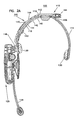
- FIGS 1 and 2A-2B are perspective and cross-sectional views of an exemplary headset assembly in accordance with one embodiment of the invention.
- the headset assembly 100 includes a headband 110 and an electronics housing 120.
- the electronics housing 120 generally encloses headset electronics, such as a circuit board, battery, etc.
- Mounted on the housing may, for example, be an earphone speaker 128, a microphone boom 126, and a touchpad 124 for operating the headset electronics.
- the earphone speaker 128 and microphone boom 126 are typically pivotally mounted to the housing 120 to facilitate comfortable positioning.
- Inwardly facing pads 130 formed, for example, from a polyethylene foam, may be mounted on the headset assembly 100.
- a battery 900 is provided on the housing 120 as well.
- the exemplary headset assembly 100 illustrates a number of features which enhance the convenience and comfort for a user.
- the exemplary headband 110 advantageously allows a user to adjust the unstressed width of the headband.
- the headband 110 generally includes two headpieces 112 and 114, pivotally connected to one another, and a mechanism for limiting the pivotal movement of the headpieces so that the unstressed width of the headband 110 may be adjusted.
- At least one of the headpieces is relatively flexible so as to provide tension against the head of a user and thereby hold the headset in place.
- the two headpieces 112 and 114 include a relatively flexible headpiece 114 and a relatively rigid support headpiece 112.
- the support headpiece 112 generally provides a supporting structure against which the flexible headpiece 114 may bend so as to provide the desired head tension to keep the headset in place.
- the headpieces 112 and 114 may be made of a number of different materials.
- the flexible headpiece 114 may be formed from a flexible plastic while the support headpiece 112 may be formed from a relatively more rigid plastic material.
- One suitable plastic is Nylon, for example.
- the flexible headpiece 114 is pivotally coupled to the support headpiece 112 near the end of the support headpiece 112 using a pin 117.
- the pivotally connection may be formed in other manners.
- the two headpieces 112 and 114 may be integrally formed with a relatively thin portion forming an integral hinge between the two headpieces.
- the mechanism for limiting the pivotal movement of the flexible headpiece 114 with respect to the support headpiece 112 includes a tab 162 slidably mounted on a portion 164 of the support headpiece 112, as best shown in Figure 2B.
- the tab 162 is moved outwardly and inwardly, the unstressed width of the headband increases and decreases, respectively. In this manner, the unstressed width of the headband 110 may be appropriately adjusted to comfortably fit a user's head.
- the tab 162 includes a surface 166 which engages the flexible headpiece 114 to both limit the pivotal movement of the flexible headpiece 114 as well as provide a structure against which the flexible headpiece 114 may flex or bend to provide head tension.
- the flexible headpiece 114 can be pivotally moved until it contacts the surface 166 at which point further movement of the flexible headpiece I 14 results in the creation of a tensile force from the headpiece 114.
- the exemplary tab 162 includes an upper portion 165 and a lower portion 167, mounted to the extended portion 164 of the support headpiece 112 using a pin 117.
- the tab 162 includes a set of groves 168a which mate with a set of groves 168b on a surface of the headpiece portion 164 for setting the position of the tab 162 (and the width of the headband 100)-
- a leaf spring 169 may be provided to bias the grove sets 168a and 168b against one another. The leaf spring bias generally allows the tab to be readily repositioned yet prevents the tab from slipping on the headpiece portion 164 when pressure from the flexible headpiece is applied.
- tab 162 is provided by way of example only.
- a wide variety of other structures and mechanisms may be used to limit the pivotal movement of the flexible headpiece 114.
- a mechanism having a surface which is moved in a different plane than that of tab surface 166 may be used.
- the present invention is not limited to three or any other fixed number of unstressed widths.
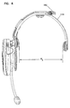
- the tab 162 is configured to allow pivotal movement of the flexible headpiece 114 to three different widths. More particularly, Figure 3 illustrates the tab 162 at an inner most position, which allows the flexible headpiece to pivotally move outward to an unstressed width W1. This provides the narrowest headband unstressed width and would be suitable for users having smaller head sizes.
- Figure 4 shows the tab 162 at an intermediate position, which allows the flexible headpiece 114 to pivotally move to an unstressed width W2. This provides an intermediate headband unstressed width and would be suitable for slightly larger head sizes.
- Figure 5 depicts tab 162 at an outermost position, which allows the flexible headpiece to be pivotally moved to an unstressed width W3. This provides the widest headband unstressed width W3 for accommodating larger head sizes.
- the three unstressed widths W1, W2, and W3, for the flexible headpiece 114 may be suitably selected to cover the broadest range of head sizes.
- a user slides the tab 162 to a position which provides a desired unstressed headband width.
- the unstressed width is slightly narrower than the user's head.
- the user then spreads the headband beyond its unstressed width by flexing the flexible headpiece 114 and slips the headband over his/her head.
- the tension provided by the stressed headband holds the headset in place.
- the unstressed width of the above-described headband can advantageously be adjusted for various head sizes.
- Conventional headbands as noted above, have only one unstressed width. With these conventional headbands, smaller heads are subject to less tension than larger heads. This often results in excessive tension on larger heads causing discomfort and too little tension on smaller heads making the headset prone to movement.
- the above headband alleviates these problems and allows users with different sized heads to receive more comparable head tension.
- the illustrated headset assembly 100 further provides an electronics housing which may be readily removed from the headband 110 and, for example, attached to a hat of a user.
- the hat may, for example, be a baseball cap, a visor, and so forth.
- an exemplary clip member 140 is provided to facilitate the interchangeability of the electronics housing 120 between a hat and a headband. While, the invention is not so limited, the clip member 140 may, for example, be made of a substantially rigid plastic material, such as Nylon.
- the exemplary clip member 140 includes an upper portion 141 for attaching the clip member to the headband 110 or hat, and a lower portion 148 to which the electronics housing 120 may be coupled.
- the clip member upper portion 141 includes two arms 142 and 144 which form a slot 146 therebetween.
- a portion 118 of the support headpiece 112 is slidably received by the slot 146 of the clip member 140.
- the two arms 142 and 144 may be biased against one another with sufficient force to allow the clip member 140 to be slidably moved with respect to the support headpiece 112 while retaining the clip member 140 at a desired position with respect to the support headpiece 112 under normal conditions.
- the clip member arms may be formed separately or from one integral molding.
- the received portion 118 of the support headpiece 112 may be recessed with respect to an outer surface 119 of the support headpiece 112.
- the recess may be sufficiently deep to allow the outer surfaces 143 and 149 of the clip member arms 142 and 144 to be relatively flush with the outer surface 119 of the support headpiece 112.
- the support headpiece 112 may include a tab which engages an opening in the clip member 140. The tab may be depressed for removing the clip member 140 from the headband 110.
- a depressable button may be provided on the clip member to secure the clip member 140 to the headband 110. The button may be depressed as the clip member 140 is slid downwardly against the headband to allow the clip member to be removed from the headband 110.
- the clip member upper portion 141 may also be used to attach the electronics housing to a hat.
- the clip member 140 may attach to a hat by slidably receiving a hat between the clip member arms 142 and 144.
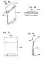
- an adapter 700 is provided to attach the clip member 140 to a hat.
- the exemplary adapter 700 generally includes two legs 702 and 704, which are typically biased toward one another.
- the leg 704 includes an upper flange 706 having a slot 710 (as best shown in Figure 7B) and a lower flange 708.
- the slot 710 receives clip member arm 142.
- the adapter 700 is slid down the arm 142 until the lower flange 708 clips beneath the pad 130.
- a hat is attached to the adapter by sliding it between the adapter arms 702 and 704.
- the cap adapter 700 may, for example, be formed from a stainless steel.
- the above described clip member advantageously allows the electronics housing to be interchangeably connected to a headband and a hat.
- the exemplary clip member is illustrative only. The present invention is not so limited.
- a clip member having only one leg which is received by a slot formed by the headband may be used to facilitate interchanging of an electronics housing.
- a hat adapter could be employed to attach the clip member to a hat.
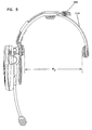
- the exemplary headset assembly 100 further includes an electronics housing 120 which may be pivoted away from a user's ear.
- the electronic housing 120 is pivotally coupled to the headband 110 using a hinge 180.
- the hinge 180 may, for example, include a variable friction pivot pin having a friction suitably selected to sufficiently hold electronic package 120 away from the user's ear while still allowing the electronics package 120 to be readily pivoted. This allows for the electronic package 120 to be positioned against the user's ear during periods of use and swung away from the user's ear during periods of nonuse or as desired to increase the comfort of the user.
- the electronics housing 120 is pivotally coupled with the headband 110 via the clip member 140.
- the electronics housing 120 is pivotally coupled with the clip member 140, for example, at the clip member extending portion 148.
- the clip member 140 is in turn attached to the headband 110, as discussed above. This allows the electronics housing 120 to be swung away from the user's ear when it is attached to a hat as well as a headband.
- the exemplary electronics housing 120 further includes a battery 900.
- a portion of the battery 900 may lie outside of the electronics housing when attached, as best shown in Figure 2.
- a portion of the battery 900 may occupy the space between the speaker 128 and the electronics housing 120.
- the housing 120 may be detached from the headband 110 and used for communication.
- the battery 900 By disposing the battery 900 between the housing 120 and the speaker 128, otherwise unoccupied space is used and the width of the housing 120 may be reduced while still providing sufficient power for the electronics in the housing 120.
- the battery 900 may be attached to the electronics housing 120 in a number of different manners.
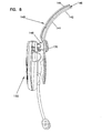
- the battery 900 is slidably received by a slot 902 in the electronics housing 120, as best illustrated in Figure 9.
- the received portion of the battery 900 and the slot 902 may have shapes or structural features which mate together to retain the battery 900.
- the slot 902 may include flanges 904, on each side of the slot 902, which mate with corresponding recesses 906 on the battery 900.
- a portion of a lower region of the battery 900 extends beyond an upper region of the battery 900 to form the battery recesses 906.
- a latch 908 may further be provided to secure the battery 900 in the axial direction of the slot 902.
- the latch 908 may, for example, be a spring loaded latch which is disposed upward while the battery 900 is inserted and which moves downward to engage a notch 910 in the battery 900 when the battery is fully inserted. To remove the battery 900, the latch 908 may be biased upwardly.
- the present invention is applicable to a wide variety of headset assemblies incorporating enhanced ergonomic features. While the illustrated embodiment incorporates a number of ergonomic features, the present invention is not so limited. Headset assemblies including any one or a combination of the features are covered by the present invention. Accordingly, the present invention should not be considered limited to the particular examples described above, but rather should be understood to cover all aspects of the invention as fairly set out in the attached claims. Various modifications as well as numerous equivalent structures to which the present invention may be applicable will be readily apparent to those of skill in the art to which the present invention is directed upon review of the present specification. The claims are intended to cover such modifications and structures.
Abstract
Description
- The present invention relates generally to headset assemblies and, more particularly, to a headset assembly having improved ergonomics.
- Headset assemblies are frequently used in a wide variety of applications and across a broad range of industries. For example, in the fast food industry, one or more employees at drive-through fast food restaurants typically wear a headset assembly to receive orders from patrons in the drive-through lane. Similarly, in the banking industry, tellers at banks having drive-through lanes may wear headset assemblies to communicate with customers. In the retail industry, headsets are commonly used by stockroom and other employees to communicate with one another within a large area, such as a department store or a warehouse.
- A typical headset assembly includes a headband and an electronics housing. The headband typically consists of one single-rate leaf spring having only one unstressed width, but which is flexed to fit different sized heads. The electronics housing is typically attached to one end of the headband and usually includes an earphone speaker, a microphone boom, and the electronic circuitry necessary to operate the earphone and microphone. While being commonplace in today's society, conventional headsets are extremely uncomfortable and inconvenient to use.
- US-A-5 117 464 teaches clip-on headphones which include stereo speakers which may be clipped to a cross-over headband made from spring steel or plastic. The stereo speakers are connected to a socket via slide rods. The socket is, in turn, connected to the headband via a female clip. The headband relies on resiliency to provide width adjustment and tension between the male clips which hold the headband to the head of a wearer.
- US-A-5 113 428 discloses a cordless telephone device which includes a top headband connected to two side pieces, and a back headband pivotally connected to the two side pieces via pivot pins. The top headband and back headband are adjustable with a slidable clip, respectively, to accommodate different sized heads.
- EP-A-0 019 838 discloses a clip for securing a unit having an earphone capsule and microphone capsule to a military helmed. A microphone is attached by a frictional hinge to the unit. The unit is attached by a second frictional hinge to the clip. The device is shaped so that it may be used when a gas mask is worn.
- US-A-4 930 148 discloses a headband radiophone which includes a circular supporting band and two earphones mounted on respective ends thereof. The earphones are connected to the supporting band using adjusting bars, which may be adjusted to fit the size of a wearer's head. The circular supporting band provides tension to hold the radiophone to the wearer's head.
- Generally the present invention relates to a headset assembly as defined in the claims having increased comfort and convenience of use. In accordance with one embodiment of the invention, a headset assembly is provided which includes a first headpiece pivotally coupled to a second flexible headpiece. The headset assembly further includes means for limiting the pivotal movement of the flexible headpiece with respect to the first headpiece. This allows the tension of the headset assembly to be suitable adjusted to the head size of the wearer.
- In accordance with another embodiment of the invention, a headset assembly which includes a headband and an electronics housing pivotally coupled to the headpiece is provided. The pivotal coupling of the electronics housing with respect to the headband allows the electronics housing to be swung away from a user's ear and provides additional comfort to the user.
- In accordance with yet another embodiment of the invention, there is provided a headset assembly having an electronics housing removably coupled to a headband. The electronics housing may, for example, be removably coupled between a headband and a cap of a user. The headset assembly may include a clip member for removably coupling the headband to the electronics housing.
- The above summary of the present invention is not intended to describe each illustrated embodiment. The figures and the detailed description which follow more particularly exemplify these embodiments.
- The invention may be more completely understood in consideration of the following detailed description of various embodiments of the invention in connection with the accompanying drawings, in which:
- Figure 1 is a perspective view of an exemplary headset assembly in accordance with one embodiment of the present invention;
- Figures 2A and 2B are front cross sectional views of the headset assembly of Figure 1;
- Figures 3-5 are front plan views of the exemplary headset assembly of Figure 1 shown at different width settings;
- Figure 6 is a front plan view of an exemplary clip member coupled to an electronic housing in accordance with one embodiment of the present invention;
- Figures 7A-7B are views of an exemplary adapter in accordance with one embodiment of the invention;
- Figure 8 is a front plan view of the exemplary headset assembly of Figure 1; and
- Figure 9 is an exploded perspective view of the headset assembly of Figure 1.
-
- While the invention is amenable to various modifications and alternative forms, specifics thereof have been shown by way of example in the drawings and will be described in detail. It should be understood, however, that the intention is not to limit the invention to the particular embodiments described. on the contrary, the intention is to cover all modifications, equivalents, and alternatives falling within the scope of the invention as defined by the appended claims.
- The present invention generally relates to headset assemblies having one or more ergonomic features which increase the comfort and convenience of the headset assembly for a user. An appreciation of various aspects and features of the invention will be gained through a discussion of an exemplary embodiment. While the exemplary embodiment illustrates a headset assembly which incorporates a number of these features, the present invention is not so limited. Headset assemblies including any one or combination of the features are intended to be covered by the present invention.
- Figures 1 and 2A-2B are perspective and cross-sectional views of an exemplary headset assembly in accordance with one embodiment of the invention. The
headset assembly 100 includes aheadband 110 and anelectronics housing 120. Theelectronics housing 120 generally encloses headset electronics, such as a circuit board, battery, etc. Mounted on the housing may, for example, be anearphone speaker 128, amicrophone boom 126, and atouchpad 124 for operating the headset electronics. As should be appreciated, theearphone speaker 128 andmicrophone boom 126 are typically pivotally mounted to thehousing 120 to facilitate comfortable positioning. Inwardly facingpads 130 formed, for example, from a polyethylene foam, may be mounted on theheadset assembly 100. As will be discussed more fully below, abattery 900 is provided on thehousing 120 as well. - As noted above, the
exemplary headset assembly 100 illustrates a number of features which enhance the convenience and comfort for a user. Theexemplary headband 110 advantageously allows a user to adjust the unstressed width of the headband. Theheadband 110 generally includes twoheadpieces headband 110 may be adjusted. At least one of the headpieces is relatively flexible so as to provide tension against the head of a user and thereby hold the headset in place. - In the illustrated embodiment, the two
headpieces flexible headpiece 114 and a relativelyrigid support headpiece 112. Thesupport headpiece 112 generally provides a supporting structure against which theflexible headpiece 114 may bend so as to provide the desired head tension to keep the headset in place. Theheadpieces flexible headpiece 114 may be formed from a flexible plastic while thesupport headpiece 112 may be formed from a relatively more rigid plastic material. One suitable plastic is Nylon, for example. - The
flexible headpiece 114 is pivotally coupled to thesupport headpiece 112 near the end of thesupport headpiece 112 using apin 117. However the invention is not so limited. The pivotally connection may be formed in other manners. For example, the twoheadpieces - In the exemplary embodiment, the mechanism for limiting the pivotal movement of the
flexible headpiece 114 with respect to thesupport headpiece 112 includes atab 162 slidably mounted on aportion 164 of thesupport headpiece 112, as best shown in Figure 2B. In general, as thetab 162 is moved outwardly and inwardly, the unstressed width of the headband increases and decreases, respectively. In this manner, the unstressed width of theheadband 110 may be appropriately adjusted to comfortably fit a user's head. - As best shown in Figures 2A and 2B, the
tab 162 includes asurface 166 which engages theflexible headpiece 114 to both limit the pivotal movement of theflexible headpiece 114 as well as provide a structure against which theflexible headpiece 114 may flex or bend to provide head tension. Theflexible headpiece 114 can be pivotally moved until it contacts thesurface 166 at which point further movement of the flexible headpiece I 14 results in the creation of a tensile force from theheadpiece 114. - As best illustrated in Figure 2B, the
exemplary tab 162 includes anupper portion 165 and alower portion 167, mounted to theextended portion 164 of thesupport headpiece 112 using apin 117. Thetab 162 includes a set ofgroves 168a which mate with a set ofgroves 168b on a surface of theheadpiece portion 164 for setting the position of the tab 162 (and the width of the headband 100)- Aleaf spring 169 may be provided to bias the grove sets 168a and 168b against one another. The leaf spring bias generally allows the tab to be readily repositioned yet prevents the tab from slipping on theheadpiece portion 164 when pressure from the flexible headpiece is applied. - It should be appreciated that the
tab 162 is provided by way of example only. A wide variety of other structures and mechanisms may be used to limit the pivotal movement of theflexible headpiece 114. For example, a mechanism having a surface which is moved in a different plane than that oftab surface 166 may be used. Moreover, the present invention is not limited to three or any other fixed number of unstressed widths. - As illustrated in Figures 3-5, in the exemplary embodiment, the
tab 162 is configured to allow pivotal movement of theflexible headpiece 114 to three different widths. More particularly, Figure 3 illustrates thetab 162 at an inner most position, which allows the flexible headpiece to pivotally move outward to an unstressed width W1. This provides the narrowest headband unstressed width and would be suitable for users having smaller head sizes. Figure 4 shows thetab 162 at an intermediate position, which allows theflexible headpiece 114 to pivotally move to an unstressed width W2. This provides an intermediate headband unstressed width and would be suitable for slightly larger head sizes. Finally, Figure 5 depictstab 162 at an outermost position, which allows the flexible headpiece to be pivotally moved to an unstressed width W3. This provides the widest headband unstressed width W3 for accommodating larger head sizes. The three unstressed widths W1, W2, and W3, for theflexible headpiece 114 may be suitably selected to cover the broadest range of head sizes. - In operation, a user slides the
tab 162 to a position which provides a desired unstressed headband width. - Typically the unstressed width is slightly narrower than the user's head. The user then spreads the headband beyond its unstressed width by flexing the
flexible headpiece 114 and slips the headband over his/her head. The tension provided by the stressed headband holds the headset in place. - The unstressed width of the above-described headband can advantageously be adjusted for various head sizes. Conventional headbands, as noted above, have only one unstressed width. With these conventional headbands, smaller heads are subject to less tension than larger heads. This often results in excessive tension on larger heads causing discomfort and too little tension on smaller heads making the headset prone to movement. The above headband alleviates these problems and allows users with different sized heads to receive more comparable head tension.
- As best illustrated in Figures 2A and 6-7, the illustrated
headset assembly 100 further provides an electronics housing which may be readily removed from theheadband 110 and, for example, attached to a hat of a user. The hat may, for example, be a baseball cap, a visor, and so forth. In the illustrated embodiment, anexemplary clip member 140, is provided to facilitate the interchangeability of theelectronics housing 120 between a hat and a headband. While, the invention is not so limited, theclip member 140 may, for example, be made of a substantially rigid plastic material, such as Nylon. - The
exemplary clip member 140 includes anupper portion 141 for attaching the clip member to theheadband 110 or hat, and alower portion 148 to which theelectronics housing 120 may be coupled. The clip memberupper portion 141 includes twoarms slot 146 therebetween. To attach theclip member 140 with theheadband 110, aportion 118 of thesupport headpiece 112 is slidably received by theslot 146 of theclip member 140. The twoarms clip member 140 to be slidably moved with respect to thesupport headpiece 112 while retaining theclip member 140 at a desired position with respect to thesupport headpiece 112 under normal conditions. The clip member arms may be formed separately or from one integral molding. - As best shown in Figure 2A, the received
portion 118 of thesupport headpiece 112 may be recessed with respect to anouter surface 119 of thesupport headpiece 112. The recess may be sufficiently deep to allow theouter surfaces clip member arms outer surface 119 of thesupport headpiece 112. To secure theclip member 140 to theheadband 110, thesupport headpiece 112 may include a tab which engages an opening in theclip member 140. The tab may be depressed for removing theclip member 140 from theheadband 110. In an alternate embodiment, a depressable button may be provided on the clip member to secure theclip member 140 to theheadband 110. The button may be depressed as theclip member 140 is slid downwardly against the headband to allow the clip member to be removed from theheadband 110. - The clip member
upper portion 141 may also be used to attach the electronics housing to a hat. For example, theclip member 140 may attach to a hat by slidably receiving a hat between theclip member arms adapter 700 is provided to attach theclip member 140 to a hat. Theexemplary adapter 700 generally includes twolegs leg 704 includes anupper flange 706 having a slot 710 (as best shown in Figure 7B) and alower flange 708. To attach theadapter 700 to theclip member 140, theslot 710 receivesclip member arm 142. Theadapter 700 is slid down thearm 142 until thelower flange 708 clips beneath thepad 130. A hat is attached to the adapter by sliding it between theadapter arms cap adapter 700 may, for example, be formed from a stainless steel. - The above described clip member advantageously allows the electronics housing to be interchangeably connected to a headband and a hat. The exemplary clip member is illustrative only. The present invention is not so limited. For example, a clip member having only one leg which is received by a slot formed by the headband may be used to facilitate interchanging of an electronics housing. In this embodiment, a hat adapter could be employed to attach the clip member to a hat.
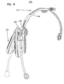
- As illustrated in Figure 8, the
exemplary headset assembly 100 further includes anelectronics housing 120 which may be pivoted away from a user's ear. Generally theelectronic housing 120 is pivotally coupled to theheadband 110 using ahinge 180. Thehinge 180 may, for example, include a variable friction pivot pin having a friction suitably selected to sufficiently holdelectronic package 120 away from the user's ear while still allowing theelectronics package 120 to be readily pivoted. This allows for theelectronic package 120 to be positioned against the user's ear during periods of use and swung away from the user's ear during periods of nonuse or as desired to increase the comfort of the user. - In the exemplary embodiment, the
electronics housing 120 is pivotally coupled with theheadband 110 via theclip member 140. In particular, theelectronics housing 120 is pivotally coupled with theclip member 140, for example, at the clipmember extending portion 148. Theclip member 140 is in turn attached to theheadband 110, as discussed above. This allows theelectronics housing 120 to be swung away from the user's ear when it is attached to a hat as well as a headband. - As best illustrated in Figures 2 and 9, the
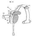
exemplary electronics housing 120 further includes abattery 900. A portion of thebattery 900 may lie outside of the electronics housing when attached, as best shown in Figure 2. For example, a portion of thebattery 900 may occupy the space between thespeaker 128 and theelectronics housing 120. By attaching thebattery 900 to theelectronics housing 120, the need for wiring between one end of theheadset 100 and theelectronics housing 120 is eliminated. In addition, thehousing 120 may be detached from theheadband 110 and used for communication. By disposing thebattery 900 between thehousing 120 and thespeaker 128, otherwise unoccupied space is used and the width of thehousing 120 may be reduced while still providing sufficient power for the electronics in thehousing 120. - The
battery 900 may be attached to theelectronics housing 120 in a number of different manners. In the exemplary embodiment, thebattery 900 is slidably received by aslot 902 in theelectronics housing 120, as best illustrated in Figure 9. For securing thebattery 900 in theslot 902, the received portion of thebattery 900 and theslot 902 may have shapes or structural features which mate together to retain thebattery 900. For example, theslot 902 may includeflanges 904, on each side of theslot 902, which mate withcorresponding recesses 906 on thebattery 900. In the exemplary embodiment, a portion of a lower region of thebattery 900 extends beyond an upper region of thebattery 900 to form the battery recesses 906. Alatch 908 may further be provided to secure thebattery 900 in the axial direction of theslot 902. Thelatch 908 may, for example, be a spring loaded latch which is disposed upward while thebattery 900 is inserted and which moves downward to engage anotch 910 in thebattery 900 when the battery is fully inserted. To remove thebattery 900, thelatch 908 may be biased upwardly. - As noted above, the present invention is applicable to a wide variety of headset assemblies incorporating enhanced ergonomic features. While the illustrated embodiment incorporates a number of ergonomic features, the present invention is not so limited. Headset assemblies including any one or a combination of the features are covered by the present invention. Accordingly, the present invention should not be considered limited to the particular examples described above, but rather should be understood to cover all aspects of the invention as fairly set out in the attached claims. Various modifications as well as numerous equivalent structures to which the present invention may be applicable will be readily apparent to those of skill in the art to which the present invention is directed upon review of the present specification. The claims are intended to cover such modifications and structures.
Claims (15)
- A headset assembly (100), comprising:a headband (110) including a first headpiece (112) and a second headpiece (114) which is flexible, the first headpiece (112) having a first end portion (164) pivotally coupled to a firstend portion of the second headpiece (114) by a pivotal connection (117) and having a second end portion separated from a second end portion of the second headpiece (114), thereby defining a width between the second end portions for receiving a head of a wearer; andadjusting means (162) movably engageable with the first (112) and second (114) headpieces for adjusting a maximum range of pivotal movement of the second headpiece (114) with respect to the first headpiece (112) so as to vary the width of the headband (110) without stressing the first and second headpieces (112,114).
- The headset assembly (100) of claim 1, wherein the adjusting means is a tab (162) movably engageable with the first (112) and second (114) headpieces for adjusting a maximum range of pivotal movement of the second headpiece (114) with respect to the first headpiece (112).
- The headset assembly (100) of claim 2, wherein the pivotal connection is a pin (117) at a fixed location.
- The headset assembly (100) of claim 3, wherein the tab (162) is mounted on a portion (164) of the first headpiece (112) proximate the pin (117).
- The headset assembly (100) of claim 2, wherein the tab (162) is movable with respect to the first headpiece (112), the tab (162) including a surface (166) which engages the first end portion of the second headpiece (114) to limit a maximum range of pivotal movement between the first (112) and second (114) headpieces without stressing the first (112) and second (114) headpieces.
- The headset assembly (100) of claim 5 wherein the tab (162) can move to one of a plurality of different, discrete locations, each location being associated with a different unstressed width (W1,W2,W3) of the headset assembly (100).
- The headset assembly (100) of claim 6 wherein the second headpiece (114) pivots until engaging the tab surface (166) and thereafter bends against the tab surface (166) so as to stress the second headpiece (114) for providing tension between the second end portions.
- The headset assembly (100) of claim 1, further comprising:an electronics housing (120) pivotally coupled to the second end portion of the first headpiece (112) for being positioned adjacent an ear of the wearer, wherein a speaker (128) is mounted on the housing (120).
- The headset assembly (100) of claim 8, wherein the first headpiece (112) includes a received portion (118) removably coupled to a clip member (140), wherein the clip member pivotally couples the electronics housing to the second end portion of the first headpiece (112).
- The headset assembly (100) of claim 1, wherein each of the second end portions are provided with inwardly facing pads (130).
- The headset assembly (100) of claim 10 further including a hinge (180) with a friction pivot pin disposed proximate the pad (130) on the second end portion of the first headpiece (112) for pivotally coupling the second end portion of the first headpiece (112) to an end portion of the electronics housing (120) to provide an off center pivot axis which allows the housing (120) to pivot against and away from the ear of the wearer when the headset is worn.
- The headset assembly (100) of claim 1, wherein the first headpiece (112) is substantially rigid.
- The headset assembly (100) of claim 9, further including an adapter (700) capable of being removably coupled to the clip member (140), the adapter (700) being configured to be removably mounted on a hat.
- The headset assembly (100) of claim 5, wherein the second headpiece (114) bends against the surface (166) of the tab (162) so as to provide tension between the second end portions of the headpieces (112, 114).
- The headset assembly (100) of claim 7 wherein the pivotal connection connecting the first end portions of the first (112) and second (114) headpieces is a pin (117) disposed on a top portion of the headband (110), the headset assembly further comprising an electronics housing (120), pivotally coupled to the second end portion of the first headpiece (112) for being positioned adjacent an ear of the wearer, wherein a speaker (128) is mounted to the housing (120).
Applications Claiming Priority (3)
| Application Number | Priority Date | Filing Date | Title |
|---|---|---|---|
| US08/837,440 US6754361B1 (en) | 1997-04-17 | 1997-04-17 | Ergonomic headset assembly |
| US837440 | 1997-04-17 | ||
| PCT/US1998/007680 WO1998047311A1 (en) | 1997-04-17 | 1998-04-17 | Headset assembly |
Publications (2)
| Publication Number | Publication Date |
|---|---|
| EP0976299A1 EP0976299A1 (en) | 2000-02-02 |
| EP0976299B1 true EP0976299B1 (en) | 2004-10-06 |
Family
ID=25274445
Family Applications (1)
| Application Number | Title | Priority Date | Filing Date |
|---|---|---|---|
| EP98918307A Expired - Lifetime EP0976299B1 (en) | 1997-04-17 | 1998-04-17 | Headset assembly |
Country Status (10)
| Country | Link |
|---|---|
| US (2) | US6754361B1 (en) |
| EP (1) | EP0976299B1 (en) |
| JP (1) | JP2001520831A (en) |
| CN (1) | CN1254492A (en) |
| AU (1) | AU734513B2 (en) |
| BR (1) | BR9808559A (en) |
| CA (1) | CA2286634C (en) |
| DE (1) | DE69826850T2 (en) |
| ES (1) | ES2230686T3 (en) |
| WO (1) | WO1998047311A1 (en) |
Families Citing this family (111)
| Publication number | Priority date | Publication date | Assignee | Title |
|---|---|---|---|---|
| DK199801716A (en) | 1998-12-23 | 2000-06-24 | Gn Netcom As | Headset |
| US6430299B1 (en) * | 2000-03-16 | 2002-08-06 | 3M Innovative Properties Company | Headset assembly including replaceable battery |
| US6332223B1 (en) | 2000-04-05 | 2001-12-25 | Gray Matter Holdings, Llc | Apparatus and method for making an ear warmer having interior seams |
| DE10036932A1 (en) * | 2000-07-28 | 2002-02-07 | Siemens Ag | Speaker layout |
| US20020076060A1 (en) * | 2000-12-19 | 2002-06-20 | Hall Ronald W. | Programmable headset and programming apparatus and method |
| WO2002053061A2 (en) | 2000-12-29 | 2002-07-11 | Gray Matter Holdings, Llc | Ear protection device |
| US20020111197A1 (en) * | 2001-01-04 | 2002-08-15 | Fitzgerald Robert M. | Cordless telephone headset system |
| US7103392B2 (en) * | 2002-01-15 | 2006-09-05 | 3M Innovative Properties Company | Wireless intercom system |
| US6735784B2 (en) | 2002-01-28 | 2004-05-18 | 180S, Inc. | Apparatus and method for making an ear warmer and an ear warmer frame |
| US6993292B2 (en) * | 2002-02-26 | 2006-01-31 | 3M Innovative Properties Company | Self-monitoring radio network |
| DK174898B1 (en) * | 2002-06-20 | 2004-02-09 | Gn Netcom As | Headset |
| US6910911B2 (en) | 2002-06-27 | 2005-06-28 | Vocollect, Inc. | Break-away electrical connector |
| US7120388B2 (en) * | 2002-12-16 | 2006-10-10 | 3M Innovative Properties Company | Wireless intercom system and method of communicating using wireless intercom system |
| KR100933116B1 (en) * | 2003-02-07 | 2009-12-21 | 삼성전자주식회사 | 3-axis rotating headset |
| US7650649B2 (en) | 2003-08-12 | 2010-01-26 | 180S, Inc. | Ear warmer having an external frame |
| US7222373B2 (en) * | 2003-08-12 | 2007-05-29 | 180S, Inc. | Ear warmer having a membrane forming a receptacle |
| US7962970B2 (en) | 2003-08-12 | 2011-06-21 | 180S, Inc. | Ear warmer having a curved ear portion |
| US7212645B2 (en) | 2003-08-12 | 2007-05-01 | 180S, Inc. | Ear warmer with a speaker system |
| FR2865881B1 (en) * | 2004-01-29 | 2006-04-14 | Mathieu Garin | HEADPHONES |
| US8611580B2 (en) * | 2005-03-09 | 2013-12-17 | Plantronics, Inc. | Cheek stabilizer for audio headset |
| US9072328B2 (en) | 2005-06-17 | 2015-07-07 | Artisent, Llc | Hinged attachment of headgear to a helmet |
| US8028344B2 (en) | 2005-06-17 | 2011-10-04 | Artisent, Inc. | Hinged attachment of headgear to a helmet |
| KR100703323B1 (en) * | 2005-11-03 | 2007-04-03 | 삼성전자주식회사 | Headset |
| US8417185B2 (en) | 2005-12-16 | 2013-04-09 | Vocollect, Inc. | Wireless headset and method for robust voice data communication |
| US7885419B2 (en) | 2006-02-06 | 2011-02-08 | Vocollect, Inc. | Headset terminal with speech functionality |
| US7773767B2 (en) * | 2006-02-06 | 2010-08-10 | Vocollect, Inc. | Headset terminal with rear stability strap |
| USD750847S1 (en) | 2006-02-09 | 2016-03-01 | Artisent, Llc | Helmet mount |
| JP4289376B2 (en) * | 2006-08-18 | 2009-07-01 | ソニー株式会社 | headset |
| US8443466B2 (en) | 2007-01-22 | 2013-05-21 | 180S, Inc. | Ear protection device |
| US8339248B2 (en) * | 2007-04-27 | 2012-12-25 | Carroll David W | Automated audio operation support device and methods |
| CN101330766B (en) * | 2007-09-07 | 2011-07-27 | 宁波艾克赛尔电子有限公司 | Earphone microphone capable of adjusting clamping force |
| CN101459715B (en) * | 2007-12-12 | 2011-06-15 | 群康科技(深圳)有限公司 | Mobile phone and driving method thereof |
| USD626949S1 (en) | 2008-02-20 | 2010-11-09 | Vocollect Healthcare Systems, Inc. | Body-worn mobile device |
| JP4737251B2 (en) * | 2008-08-20 | 2011-07-27 | ソニー株式会社 | headphone |
| USD605629S1 (en) | 2008-09-29 | 2009-12-08 | Vocollect, Inc. | Headset |
| US8386261B2 (en) | 2008-11-14 | 2013-02-26 | Vocollect Healthcare Systems, Inc. | Training/coaching system for a voice-enabled work environment |
| EP2401865B1 (en) | 2009-02-27 | 2020-07-15 | Foundation Productions, Llc | Headset-based telecommunications platform |
| US8538058B2 (en) * | 2009-05-20 | 2013-09-17 | Rolf Eberl | Headset |
| US8160287B2 (en) * | 2009-05-22 | 2012-04-17 | Vocollect, Inc. | Headset with adjustable headband |
| US8367217B2 (en) | 2009-06-02 | 2013-02-05 | Integran Technologies, Inc. | Electrodeposited metallic-materials comprising cobalt on iron-alloy substrates with enhanced fatigue performance |
| US20120272484A1 (en) * | 2009-10-02 | 2012-11-01 | Willborn Inventstments Incorporated | Multiposition visor adaptor system |
| US8438659B2 (en) | 2009-11-05 | 2013-05-07 | Vocollect, Inc. | Portable computing device and headset interface |
| DK2352307T3 (en) * | 2009-12-04 | 2012-11-05 | Sennheiser Comm As | HEADSET WITH PAGE SUPPORT |
| CN103004235B (en) * | 2010-01-06 | 2016-02-03 | 骷髅头有限公司 | Disc jockey's audio mixing headphone |
| CA2740296C (en) | 2010-01-06 | 2018-05-01 | Skullcandy, Inc. | Dj mixing headphones |
| US8503711B2 (en) * | 2010-05-20 | 2013-08-06 | Michael Flynn | Hat mounted music system |
| US8659397B2 (en) | 2010-07-22 | 2014-02-25 | Vocollect, Inc. | Method and system for correctly identifying specific RFID tags |
| USD643400S1 (en) | 2010-08-19 | 2011-08-16 | Vocollect Healthcare Systems, Inc. | Body-worn mobile device |
| USD643013S1 (en) | 2010-08-20 | 2011-08-09 | Vocollect Healthcare Systems, Inc. | Body-worn mobile device |
| US9641926B2 (en) | 2012-06-08 | 2017-05-02 | 3M Innovative Properties Company | Modular communication device and system |
| US10075785B2 (en) | 2012-07-03 | 2018-09-11 | Microsoft Technology Licensing, Llc | Ear bud headset |
| US8861770B2 (en) * | 2013-01-23 | 2014-10-14 | Koss Corporation | Headband for personal speakers |
| US8737668B1 (en) * | 2013-01-23 | 2014-05-27 | Koss Corporation | Headband for personal speakers |
| US9167347B1 (en) | 2013-05-13 | 2015-10-20 | Rose Silberberg | Multi media wireless headphones |
| US9630005B2 (en) | 2013-08-27 | 2017-04-25 | Halo Neuro, Inc. | Method and system for providing electrical stimulation to a user |
| US9486618B2 (en) | 2013-08-27 | 2016-11-08 | Halo Neuro, Inc. | Electrode system for electrical stimulation |
| WO2015031510A1 (en) | 2013-08-27 | 2015-03-05 | Halo Neuro, Inc. | Electrode system for electrical stimulation |
| USD733677S1 (en) * | 2014-06-12 | 2015-07-07 | Asustek Computer Inc. | Headset |
| USD757683S1 (en) * | 2014-06-30 | 2016-05-31 | Cardo Systems, Inc. | Communication device |
| USD740256S1 (en) * | 2014-07-16 | 2015-10-06 | Bose Corporation | Headset |
| USD752510S1 (en) | 2014-09-22 | 2016-03-29 | Limefuel, LLC | Rechargeable battery device |
| USD752509S1 (en) | 2014-09-22 | 2016-03-29 | Limefuel, LLC | Rechargeable battery device |
| USD751983S1 (en) | 2014-09-22 | 2016-03-22 | Limefuel, LLC | Rechargeable battery device |
| USD751982S1 (en) | 2014-09-22 | 2016-03-22 | Limefuel, LLC | Rechargeable battery device |
| USD751981S1 (en) | 2014-09-22 | 2016-03-22 | Limefuel, LLC | Rechargeable battery device |
| USD751984S1 (en) | 2014-09-22 | 2016-03-22 | Limefuel, LLC | Rechargeable battery device |
| USD754637S1 (en) * | 2014-12-22 | 2016-04-26 | Plantronics, Inc. | Headset adapter and audio controller |
| US9774940B2 (en) * | 2014-12-27 | 2017-09-26 | Hand Held Products, Inc. | Power configurable headband system and method |
| AU2016215664B2 (en) | 2015-02-02 | 2018-11-08 | 3M Innovative Properties Company | Hearing protector with compartment for rechargeable battery pack |
| USD788698S1 (en) | 2015-02-18 | 2017-06-06 | Limefuel, LLC | Rechargeable battery device |
| USD780112S1 (en) | 2015-02-18 | 2017-02-28 | Limefuel, LLC | Rechargeable battery device |
| USD815032S1 (en) | 2015-02-20 | 2018-04-10 | Limefuel, LLC | Rechargeable battery device |
| CN104936065A (en) * | 2015-06-23 | 2015-09-23 | 苏州凯枫瑞电子科技有限公司 | Outdoor headband radio earphone |
| CN104954909A (en) * | 2015-06-24 | 2015-09-30 | 苏州凯枫瑞电子科技有限公司 | Radio headphones |
| CN104967939A (en) * | 2015-06-25 | 2015-10-07 | 苏州凯枫瑞电子科技有限公司 | Intelligent environment-friendly earphones |
| CN104954911A (en) * | 2015-06-25 | 2015-09-30 | 苏州凯枫瑞电子科技有限公司 | Multi-sensing volume self-adjustment type headphones |
| US20160381452A1 (en) * | 2015-06-25 | 2016-12-29 | Robert Rodriguez | Stand-alone headphones with digital music player |
| CN108290037B (en) * | 2015-10-26 | 2021-10-08 | 福禄神经学公司 | Electrode positioning system and method |
| EP3163901A1 (en) * | 2015-10-30 | 2017-05-03 | Advanced Digital Broadcast S.A. | A headset for controlling an electronic appliance |
| GB201601536D0 (en) * | 2016-01-27 | 2016-03-09 | Neurolief Ltd | Resilient head mounted device for neurostimulation and sensing of body parameters |
| US10315033B2 (en) | 2016-02-08 | 2019-06-11 | Halo Neuro, Inc. | Method and system for improving provision of electrical stimulation |
| US10485443B2 (en) | 2016-06-20 | 2019-11-26 | Halo Neuro, Inc. | Electrical interface system |
| USD847117S1 (en) * | 2016-06-28 | 2019-04-30 | Bose Corporation | Headset |
| USD786826S1 (en) | 2016-10-10 | 2017-05-16 | Premier Accessory Group LLC | Headset |
| KR101926626B1 (en) * | 2016-12-16 | 2018-12-11 | 주식회사 아모그린텍 | Wireless headphone having flexible battery |
| US10365493B2 (en) * | 2016-12-23 | 2019-07-30 | Realwear, Incorporated | Modular components for a head-mounted display |
| US10437070B2 (en) | 2016-12-23 | 2019-10-08 | Realwear, Inc. | Interchangeable optics for a head-mounted display |
| US10620910B2 (en) | 2016-12-23 | 2020-04-14 | Realwear, Inc. | Hands-free navigation of touch-based operating systems |
| US11507216B2 (en) | 2016-12-23 | 2022-11-22 | Realwear, Inc. | Customizing user interfaces of binary applications |
| CN110573065B (en) | 2017-03-08 | 2022-12-02 | 福禄神经学公司 | System for electrical stimulation |
| USD840605S1 (en) | 2017-03-10 | 2019-02-12 | Gentex Corporation | Mounting rail base plate |
| US10616686B2 (en) * | 2017-04-14 | 2020-04-07 | Bose Corporation | Stabilized headband with rotating side pad |
| US10187718B2 (en) * | 2017-04-14 | 2019-01-22 | Bose Corporation | Stabilized headband |
| KR101986257B1 (en) * | 2017-07-27 | 2019-06-07 | (주)써보레 | Support pads for headband |
| US10507324B2 (en) | 2017-11-17 | 2019-12-17 | Halo Neuro, Inc. | System and method for individualizing modulation |
| CN107920294A (en) * | 2017-11-30 | 2018-04-17 | 潍坊歌尔电子有限公司 | Headphone |
| WO2019126402A1 (en) * | 2017-12-19 | 2019-06-27 | Human, Incorporated | Ear-worn device |
| USD893446S1 (en) * | 2018-08-22 | 2020-08-18 | Robert Rodriguez | Stand-alone headphones with digital music player |
| USD880448S1 (en) * | 2018-08-23 | 2020-04-07 | Gn Audio A/S | Headset |
| USD869777S1 (en) | 2018-10-23 | 2019-12-10 | Gentex Corporation | Accessory rail connector |
| USD909338S1 (en) * | 2019-05-28 | 2021-02-02 | Xiamen Padmate Technology Co., Ltd | Headphones |
| USD925491S1 (en) * | 2019-09-30 | 2021-07-20 | Feature Products, LTD | Weight-balancing headset |
| USD968365S1 (en) | 2019-10-18 | 2022-11-01 | Jsp Limited | Ear defender |
| USD926151S1 (en) * | 2019-11-05 | 2021-07-27 | Shenzhen YAMAY digital electronics Co., LTD | Wireless headphone |
| USD941798S1 (en) * | 2020-01-21 | 2022-01-25 | 3M Innovative Properties Company | Headset |
| USD956014S1 (en) | 2020-08-13 | 2022-06-28 | Gn Audio A/S | Headset |
| JP1693865S (en) * | 2021-04-14 | 2021-08-30 | ||
| JP1693866S (en) * | 2021-04-14 | 2021-08-30 | ||
| USD981364S1 (en) | 2021-04-28 | 2023-03-21 | Gn Audio A/S | Headset |
| USD1013662S1 (en) * | 2021-08-13 | 2024-02-06 | Shenzhen Fushike Electronic Co., Ltd | Wireless earphone |
| USD1012064S1 (en) * | 2022-02-28 | 2024-01-23 | Garmin International, Inc. | Audio headset |
Family Cites Families (39)
| Publication number | Priority date | Publication date | Assignee | Title |
|---|---|---|---|---|
| US303553A (en) * | 1884-08-12 | Automatic adjustable double telephone-receiver | ||
| US299288A (en) * | 1884-05-27 | John n | ||
| US1182896A (en) * | 1915-04-27 | 1916-05-16 | Frank G Davison | Head-support for operators' instruments. |
| US1699127A (en) * | 1923-08-17 | 1929-01-15 | Pal Radio Company Inc | Ear phones |
| CH244196A (en) | 1944-04-13 | 1946-08-31 | Siemens Ag Albis | Headphone. |
| US2486267A (en) * | 1945-06-02 | 1949-10-25 | Ross E Dulinsky | Adjustable earphone |
| US3031537A (en) * | 1960-06-02 | 1962-04-24 | Maico Electronics Inc | Acoustical device |
| US3101155A (en) * | 1961-03-14 | 1963-08-20 | Dictograph Products Inc | Compact housing |
| US3167619A (en) * | 1961-09-22 | 1965-01-26 | Palmaer Tore Georg | Headstraps for earphone |
| US3306991A (en) * | 1963-06-04 | 1967-02-28 | Homer J Wood | Protective hearing aid |
| US3461463A (en) * | 1967-06-09 | 1969-08-19 | American Optical Corp | Ear protector suspension devices and the combination with headgear |
| AU450805B2 (en) * | 1968-03-19 | 1970-09-17 | Matsushita Electric Industrial Co. Ltd | Headphone type FM stereo receiver |
| DE2921434C2 (en) | 1979-05-26 | 1982-03-11 | Heinrich 6380 Bad Homburg Peiker | Headset for use on a protective helmet |
| GB2086162B (en) | 1980-05-05 | 1984-07-18 | Abramyan Evgeny A | Pulse transformer with shock excitation |
| JPS616711Y2 (en) * | 1980-05-12 | 1986-02-28 | ||
| US4484029A (en) | 1983-08-29 | 1984-11-20 | Kenney David S | Cordless telephone switch and line selector |
| US4591661A (en) | 1984-08-15 | 1986-05-27 | Joseph A. Benedetto | Portable cordless telephone transceiver-radio receiver |
| US4741030A (en) | 1986-10-31 | 1988-04-26 | Wilson Wesley T | Communications headset |
| US4882745A (en) * | 1987-05-08 | 1989-11-21 | Silver Alan H | Cordless headset telephone |
| US4904549A (en) * | 1988-11-04 | 1990-02-27 | Motorola, Inc. | Battery housing with integral latch and positive displacement apparatus |
| US5060308A (en) * | 1989-01-23 | 1991-10-22 | Bieback John S | Firefighters mask communication system |
| US4930148A (en) | 1989-10-23 | 1990-05-29 | Lee Hsiao Chung | Headband radiophone combination set |
| US5033094A (en) | 1990-06-25 | 1991-07-16 | Hung Huang Chiang | Adjustable headset |
| US5113428A (en) | 1990-09-04 | 1992-05-12 | Robert Fitzgerald | Cordless telephone headset |
| US5117464A (en) * | 1991-03-08 | 1992-05-26 | Jones Edward I | Adjustable clip-on headphones |
| US5117465A (en) * | 1991-03-15 | 1992-05-26 | Unex Corporation | Earphone with adjustable headband with progressively shallow detents |
| US5185807A (en) * | 1991-05-08 | 1993-02-09 | David Clark Company Incorporated | Headset with multi-position stirrup assemblies |
| USD342947S (en) | 1991-08-13 | 1994-01-04 | Sony Corporation | Radio tuner |
| US5333206A (en) | 1992-03-18 | 1994-07-26 | Koss Corporation | Dual element headphone |
| US5321848A (en) | 1992-09-28 | 1994-06-14 | H.M. Electronics, Inc. | Drive-up station full duplex communication system and method of using same |
| DK0629101T3 (en) * | 1993-06-11 | 2001-12-31 | Bernafon Ag | In-ear hearing aid and method for making it |
| USD364417S (en) | 1994-06-03 | 1995-11-21 | Winston Jeffrey M | Combined rubber stamp and display card |
| US5508123A (en) * | 1995-03-06 | 1996-04-16 | Wey Henn Co., Ltd. | Power supplying device |
| US5721775A (en) | 1995-05-24 | 1998-02-24 | Leifer; Richard | Cordless headset telephone |
| DE19525865A1 (en) * | 1995-07-15 | 1997-01-16 | Sennheiser Electronic | Hearing aid with an electrodynamic sound transducer |
| US5825896A (en) * | 1996-06-26 | 1998-10-20 | David Sarnoff Research Center Inc. | Hinged hearing aid |
| US5794127A (en) * | 1996-09-16 | 1998-08-11 | Lansang; Wilfredo | Headphone remote control for operating an entertainment center |
| USD394436S (en) | 1997-04-17 | 1998-05-19 | Minnesota Mining & Manufacturing Company | Headset assembly |
| US6430299B1 (en) * | 2000-03-16 | 2002-08-06 | 3M Innovative Properties Company | Headset assembly including replaceable battery |
-
1997
- 1997-04-17 US US08/837,440 patent/US6754361B1/en not_active Expired - Fee Related
-
1998
- 1998-04-17 JP JP54429298A patent/JP2001520831A/en not_active Ceased
- 1998-04-17 CN CN98804727A patent/CN1254492A/en active Pending
- 1998-04-17 DE DE69826850T patent/DE69826850T2/en not_active Expired - Fee Related
- 1998-04-17 BR BR9808559-0A patent/BR9808559A/en not_active Application Discontinuation
- 1998-04-17 CA CA002286634A patent/CA2286634C/en not_active Expired - Fee Related
- 1998-04-17 WO PCT/US1998/007680 patent/WO1998047311A1/en active IP Right Grant
- 1998-04-17 AU AU71257/98A patent/AU734513B2/en not_active Ceased
- 1998-04-17 EP EP98918307A patent/EP0976299B1/en not_active Expired - Lifetime
- 1998-04-17 ES ES98918307T patent/ES2230686T3/en not_active Expired - Lifetime
-
1999
- 1999-12-23 US US09/471,985 patent/US6406811B1/en not_active Expired - Fee Related
Also Published As
| Publication number | Publication date |
|---|---|
| EP0976299A1 (en) | 2000-02-02 |
| CN1254492A (en) | 2000-05-24 |
| US6754361B1 (en) | 2004-06-22 |
| AU734513B2 (en) | 2001-06-14 |
| DE69826850T2 (en) | 2005-10-27 |
| BR9808559A (en) | 2000-05-23 |
| ES2230686T3 (en) | 2005-05-01 |
| JP2001520831A (en) | 2001-10-30 |
| US6406811B1 (en) | 2002-06-18 |
| CA2286634C (en) | 2005-06-28 |
| AU7125798A (en) | 1998-11-11 |
| WO1998047311A1 (en) | 1998-10-22 |
| DE69826850D1 (en) | 2004-11-11 |
| CA2286634A1 (en) | 1998-10-22 |
Similar Documents
| Publication | Publication Date | Title |
|---|---|---|
| EP0976299B1 (en) | Headset assembly | |
| US6178251B1 (en) | Collar microphone | |
| US7346180B2 (en) | Self-adjusting earloop for an over-the-ear headset | |
| KR100668033B1 (en) | Headband for headsets | |
| US20060291686A1 (en) | Personal audio-set with adjustable sliding ear clip mount | |
| US5117465A (en) | Earphone with adjustable headband with progressively shallow detents | |
| US10034078B2 (en) | Earpiece positioning and retaining | |
| US6496589B1 (en) | Headset with overmold | |
| US20100206925A1 (en) | Lanyard assembly for audio device | |
| US5689558A (en) | Telephone handset holder | |
| US20020094094A1 (en) | Headset device | |
| EP2385414B1 (en) | Detachable and adjustable electronics module | |
| US20090220118A1 (en) | Behind-the-head mounted personal audio set with adjustable earphone position | |
| US6622029B1 (en) | One-hand adjustable headband headset | |
| AU2000263751B2 (en) | Headset assembly including replaceable battery | |
| US6819772B2 (en) | Personal audio-set with pivoting ear clip mount | |
| US20130310113A1 (en) | Cheek stabilizer for audio headset | |
| CA2501605C (en) | Headset assembly | |
| US7379557B2 (en) | Communication headset with auxiliary positioning device | |
| KR20030086291A (en) | Electronic device clip | |
| KR100648503B1 (en) | Ear hanging type earphone | |
| WO2003075607A1 (en) | Personal audio-set with pivoting ear clip mount | |
| CN115604615A (en) | Earphone with adjustable support | |
| EP1684542A1 (en) | Communication headset |
Legal Events
| Date | Code | Title | Description |
|---|---|---|---|
| PUAI | Public reference made under article 153(3) epc to a published international application that has entered the european phase |
Free format text: ORIGINAL CODE: 0009012 |
|
| 17P | Request for examination filed |
Effective date: 19991019 |
|
| AK | Designated contracting states |
Kind code of ref document: A1 Designated state(s): DE ES FR GB IT |
|
| 17Q | First examination report despatched |
Effective date: 20010802 |
|
| GRAP | Despatch of communication of intention to grant a patent |
Free format text: ORIGINAL CODE: EPIDOSNIGR1 |
|
| GRAS | Grant fee paid |
Free format text: ORIGINAL CODE: EPIDOSNIGR3 |
|
| GRAA | (expected) grant |
Free format text: ORIGINAL CODE: 0009210 |
|
| AK | Designated contracting states |
Kind code of ref document: B1 Designated state(s): DE ES FR GB IT |
|
| REG | Reference to a national code |
Ref country code: GB Ref legal event code: FG4D |
|
| REF | Corresponds to: |
Ref document number: 69826850 Country of ref document: DE Date of ref document: 20041111 Kind code of ref document: P |
|
| PG25 | Lapsed in a contracting state [announced via postgrant information from national office to epo] |
Ref country code: IT Free format text: LAPSE BECAUSE OF NON-PAYMENT OF DUE FEES Effective date: 20050417 |
|
| REG | Reference to a national code |
Ref country code: ES Ref legal event code: FG2A Ref document number: 2230686 Country of ref document: ES Kind code of ref document: T3 |
|
| PLBE | No opposition filed within time limit |
Free format text: ORIGINAL CODE: 0009261 |
|
| STAA | Information on the status of an ep patent application or granted ep patent |
Free format text: STATUS: NO OPPOSITION FILED WITHIN TIME LIMIT |
|
| ET | Fr: translation filed | ||
| 26N | No opposition filed |
Effective date: 20050707 |
|
| PGFP | Annual fee paid to national office [announced via postgrant information from national office to epo] |
Ref country code: ES Payment date: 20080428 Year of fee payment: 11 Ref country code: DE Payment date: 20080602 Year of fee payment: 11 |
|
| PGFP | Annual fee paid to national office [announced via postgrant information from national office to epo] |
Ref country code: FR Payment date: 20080417 Year of fee payment: 11 |
|
| PGFP | Annual fee paid to national office [announced via postgrant information from national office to epo] |
Ref country code: GB Payment date: 20080429 Year of fee payment: 11 |
|
| GBPC | Gb: european patent ceased through non-payment of renewal fee |
Effective date: 20090417 |
|
| REG | Reference to a national code |
Ref country code: FR Ref legal event code: ST Effective date: 20091231 |
|
| PG25 | Lapsed in a contracting state [announced via postgrant information from national office to epo] |
Ref country code: DE Free format text: LAPSE BECAUSE OF NON-PAYMENT OF DUE FEES Effective date: 20091103 |
|
| PG25 | Lapsed in a contracting state [announced via postgrant information from national office to epo] |
Ref country code: GB Free format text: LAPSE BECAUSE OF NON-PAYMENT OF DUE FEES Effective date: 20090417 Ref country code: FR Free format text: LAPSE BECAUSE OF NON-PAYMENT OF DUE FEES Effective date: 20091222 |
|
| REG | Reference to a national code |
Ref country code: ES Ref legal event code: FD2A Effective date: 20090418 |
|
| PG25 | Lapsed in a contracting state [announced via postgrant information from national office to epo] |
Ref country code: ES Free format text: LAPSE BECAUSE OF NON-PAYMENT OF DUE FEES Effective date: 20090418 |