EP0978628A2 - Equipment for stowing and handling rods used in drilling rigs - Google Patents
Equipment for stowing and handling rods used in drilling rigs Download PDFInfo
- Publication number
- EP0978628A2 EP0978628A2 EP99113660A EP99113660A EP0978628A2 EP 0978628 A2 EP0978628 A2 EP 0978628A2 EP 99113660 A EP99113660 A EP 99113660A EP 99113660 A EP99113660 A EP 99113660A EP 0978628 A2 EP0978628 A2 EP 0978628A2
- Authority
- EP
- European Patent Office
- Prior art keywords
- rods
- fact
- equipment according
- seat
- equipment
- Prior art date
- Legal status (The legal status is an assumption and is not a legal conclusion. Google has not performed a legal analysis and makes no representation as to the accuracy of the status listed.)
- Withdrawn
Links
Images


Classifications
-
- E—FIXED CONSTRUCTIONS
- E21—EARTH DRILLING; MINING
- E21B—EARTH DRILLING, e.g. DEEP DRILLING; OBTAINING OIL, GAS, WATER, SOLUBLE OR MELTABLE MATERIALS OR A SLURRY OF MINERALS FROM WELLS
- E21B19/00—Handling rods, casings, tubes or the like outside the borehole, e.g. in the derrick; Apparatus for feeding the rods or cables
- E21B19/14—Racks, ramps, troughs or bins, for holding the lengths of rod singly or connected; Handling between storage place and borehole
- E21B19/15—Racking of rods in horizontal position; Handling between horizontal and vertical position
- E21B19/155—Handling between horizontal and vertical position
Definitions
- the present invention refers to equipment for stowing and handling rods for use in drilling plants.
- equipment for stowing and handling rods for use in drilling plants of well-known types comprises a drilling tower; a driving head supported by the tower itself; at least one container for the rods, and a control unit for moving the rods, which is suitable for receiving the rods from the container, and is also suitable for moving the rods themselves from a loading working position, in which the rods are horizontally arranged, and a vertical screwing position, in which the rods are vertically arranged do that they can be screwed onto the driving head.
- the above mentioned lifting means comprises a beam for moving the rods which is frontally mounted to the drilling tower in order that it may rotate around a horizontal rotating axis, and a screwing device of the rods supported by the beam in order to block the rods in relation to the beam itself.
- the equipment described above suffers from certain drawbacks due to the time needed to prepare the equipment itself, this relates in particular to the time necessary to prepare the equipment for working condition, which is very long.
- Another drawback results from the fact that it is practically impossible to regulate the height of the rods in their vertical screwing working position unless the height of the entire control unit for moving the rods is regulated. This means, furthermore, that it is impossible to carry out screwing and/or unscrewing operations as far as the rods are concerned with the driving head at a height near to the handling plane.
- the aim of the present invention is to realise equipment for stowing and handling rods for use in drilling plants, which does not only permit the resolution of the drawbacks described above in a simple and economic fashion, but also results in greater flexibility
- equipment for the stowing and handling of rods for use in drilling plants comprising a service well for removing and placing individual rods, and a control unit for moving the rods suitable for moving the rods from and to the service well itself, and comprising tiltable means which can move between a flat working position and a raised working position in order to arrange the rods on an upright of the said service well, the equipment being characterised by the fact that the said tiltable means are preassembled tilting means which can be laterally installed to the service well, and comprise a support beam which can tilt around a rotating axis, and positioning means associated to the beam itself in order to position each individual rod in a set-up working position at least along the said upright.
- the number 1 indicates a drilling plant, in its entirety, which is suitable for excavating boreholes (not illustrated).
- the drilling plant 1 comprises a drilling tower 3 and a driving head 4 for the screwing of drilling rods 5 or casing pipes 5a ( Figures 4 and 5), and a quadrilateral articulated device, which is interposed between the tower 3 and the head 4, and is suitable not only for permitting the head 4 to slide along the tower 3, but also for permitting the movement of the head 4 itself from an operating working position, in which the head 4 is arranged on an upright A of the above-mentioned borehole, and a handling working position, in which the head 4 is arranged on an upright B of a service well 7 which is laterally arranged to the borehole itself.
- the drilling plant 1 also comprises equipment 8 for stowing and handling the rods 5, which comprises in its turn a control unit 9 for moving the rods 5 themselves suitable for moving the rods 5 from and towards the service well 7, and for maintaining the rods 5 at a determined height in relation to the service well 7 itself, or for arranging the rods 5 inside the service well 7 in such a way that an operator can arranged the head 4 on the rod 5.
- equipment 8 for stowing and handling the rods 5 which comprises in its turn a control unit 9 for moving the rods 5 themselves suitable for moving the rods 5 from and towards the service well 7, and for maintaining the rods 5 at a determined height in relation to the service well 7 itself, or for arranging the rods 5 inside the service well 7 in such a way that an operator can arranged the head 4 on the rod 5.
- the equipment 8 also comprises two stowing stations S1 and S2 for stowing the rods arranged opposite the control unit 9 for housing the provisioning semitrailer 10 of the rods 5, and an unloading device 11 which is suitable for moving the rods 5 themselves from the provisioning semitrailer 10 to the control unit 9.
- the equipment 8 can comprise two so-called "pipe racks" (noted but not illustrated), which can be arranged in the stations S1 and S2 in order to supply the control unit 9 with the rods 5.
- the control unit 9 for moving the rods is a pre-assembled control unit, which can be transported using the usual means of transport, and can be installed laterally to the service well 7 between the two stations S1 and S2, and comprising a platform 12 presenting a main longitudinal axis C which is arranged incidentally and transversally to the uprights A and B, and a tiltable loader 13 which is rotatably mounted in relation to the platform 12 itself in order to rotate around a tilting axis D which is arranged transversally to the axis C, and is defined by a connecting hinge 14 of the loader 13 to the platform 12.
- the loader 13 comprises a support beam 15 which is hinged to a base of the hinge 14, a carriage 16 which is slidingly mounted along the beam 15, two brackets 17 and 18 which define a longitudinal seat 19 parallel to the beam 15 itself, and a telescopic actuator device 20 connected to the beam 15 and to the platform 12 in order to rotate the beam 15 and the seat 19 between a flat working position, in which the seat 19 is arranged parallel to the C axis in order to receive a relative rod 5, and a raised working position, in which the seat 19 is arranged parallel to the B axis in order to arrange the rod 5 itself onto the upright B of the service well 7.
- the carriage 16 is part of a positioning device 21, which is suitable for positioning the rods 5 in a set-up working position in order to permit the withdrawal of the driving head 4, and comprises, for each of the brackets 17 and 18, a pair of clamps 22 which can move from and towards the seat 19 in order to clamp onto a rod 5 arranged in the seat 19 itself.
- the bracket 18 is a mobile bracket supported by the carriage 16, while the bracket 17 is a fixed bracket which is directly supported by the beam 15, and the respective clamps 22 present a clamping movement onto the seat 19 in order to prevent the rod 5 escaping from the seat 19 itself, and to permit the rod 5 to slide along the C axis by means of rollers (noted but not illustrated) on a axis which is transverse to the C axis itself.
- control unit 9 comprises a stabilising and levelling device 23 which is suitable for stabilising and levelling the platform 12 in both a longitudinal and a transverse direction, which in its turn comprises four hydraulic hammers 24 arranged in correspondence to the respective corners of the platform 12 itself, and an adjusting screw 25 which is placed in front of the hinge 14.
- the device 23 is suitable for co-operating with the unloading device 11 in order to permit a rod 5 to be coupled to the seat 19, said rod 5 having been unloaded from the provisioning semitrailer 10 by means of the unloading device 11 itself.
- the unloading device 11 comprises, for each of the brackets 17 and 18, two telescopic vertical pipes 26 arranged opposite the respective brackets 17, 18, and a pipe 27, which is supported by the relative pipes 26.
- the device 11 is provided with two blocking elements 28 arranged at the respective opposite ends in order to block in a waiting position the rods 5 provided from the stations S1, S2, and is also provided with two further blocking elements 29 arranged centrally to the pipe 27 itself in order to position a rod 5 onto the upright of the seat 19.
- the pipes 27 are moved synchronously in relation to each other by means of activating the relative hydraulic or pneumatic pipes 26, and they are tilted from and towards the stations S1 and S2 of the pipes 26 themselves in order to assist the movement of the rods 5 from and towards the elements 29.
- the unloading device 11 also comprises four stabilisers 30 for each provisioning semitrailer 10 itself in order to permit levelling in a longitudinal direction and tilting in a transverse direction in such a way as to assist the sliding of the rods 5 loaded onto the provisioning semitrailers 10 itself towards the elements 29.
- the device 11 comprises a tilting device of a well-known type, which is not illustrated, suitable for assisting the sliding of the rods 5 loaded onto the "pipe rack" itself towards the elements 29.
- Figures 4 and 5 refer to the situation in which casing pipes 5a, as well as rods 5, have to be moved, and illustrate an unloading device lls which comprises, for each station S1 and S2, two telescopic vertical pipes 26s and two horizontal pipes 27s installed on each provisioning semitrailers 10.
- the head 4 for the rods 5 is replaced by a head 4a for the pipes 5a, and it can be seen from the illustration in Figure 4 that there are many advantages as a result of being able to work on the heads 4 and 4a at a height equal to the handling height when faced with the necessity of hooking the rods 5 and the pipes 5a.
- the platform 12 is taken to the excavation site by means of normal, well-known types of means of transport, and once the platform 12 has been laterally positioned to the service well 7 with the relative C axis orientated transversally to the uprights A and B, the two stations S1 and S2 are engaged by one or two provisioning semitrailer 10, which, as illustrated in Figure 2, move and/or stow the drilling rods 5 or, alternatively, casing pipes of a well-known type which are not illustrated.
- the unloading device 11 positions the pipes 27 at a height which substantially corresponds to the height of the upper edge of the side panel of one of the two provisioning semitrailer 10, while the stabilisers 30, after having levelled each provisioning semitrailer 10, tilt the provisioning semitrailer 10 itself from the side of the control unit 9 in order to send the relative rods 5 to abut against the blocking elements 28.
- the pipes 27 are tilted to permit the rod 5 itself to slide towards the elements 28: thus, the elements 29 are disengaged from the rod 5, which rolls towards the elements 28 themselves and is blocked by coming into contact with the elements 28 themselves, and when the rod 5 is positioned on the upright of the C axis, which is to say directly above the seat 19, the pipes 27 are lowered to a point where the rod 5 itself can be inserted inside the seat 19.
- the clamps 22 block the rod 5 in the seat 19 in such a way as to prevent any movement of the rod 5 itself in relation to the seat 19 itself, and, subsequently, the telescopic actuator device 20 rotates the beam 15 around the hinge 14 in such a way as to arrange the rod 5 itself in its set-up position, which corresponds to a position in which a lower end 31 of the rod 5 itself remains substantially outside the service well7, which an upper end 32 of the rod 5 is directly screwed onto the head 4.
- the clamps 22 free the rod 5 itself, and, while the quadrilateral articulated device 6 moves the head 4 and the rod 5 onto the upright A, the device 21 moves the seat 19 back to its flat working position.
- the carriage 16 is made to slide together with the relative bracket 18 in relation to the beam 15, while the rod 5, which is firmly blocked by the clamp 22 of the bracket 17, slides inside the bracket 17 by means of the above-mentioned rollers (noted but not illustrated) on an axis transverse to the C axis.
- the positioning height of the rods 5 along the C axis can be freely regulated by simply moving the carriage 16 in relation to the beam 15, and by maintaining the rod itself firmly inside the bracket 18.
- each rod 5 is substantially controlled starting from the provisioning semitrailers until it reaches its set-up position it is practically impossible for the rod 5 itself to move accidentally and create a danger to the operators working on the drilling plant 1.
Abstract
Description
- The present invention refers to equipment for stowing and handling rods for use in drilling plants.
- Generally, equipment for stowing and handling rods for use in drilling plants of well-known types comprises a drilling tower; a driving head supported by the tower itself; at least one container for the rods, and a control unit for moving the rods, which is suitable for receiving the rods from the container, and is also suitable for moving the rods themselves from a loading working position, in which the rods are horizontally arranged, and a vertical screwing position, in which the rods are vertically arranged do that they can be screwed onto the driving head.
- As far as the kind of equipment for stowing and handling as described above is concerned, the above mentioned lifting means comprises a beam for moving the rods which is frontally mounted to the drilling tower in order that it may rotate around a horizontal rotating axis, and a screwing device of the rods supported by the beam in order to block the rods in relation to the beam itself.
- The equipment described above suffers from certain drawbacks due to the time needed to prepare the equipment itself, this relates in particular to the time necessary to prepare the equipment for working condition, which is very long. Another drawback results from the fact that it is practically impossible to regulate the height of the rods in their vertical screwing working position unless the height of the entire control unit for moving the rods is regulated. This means, furthermore, that it is impossible to carry out screwing and/or unscrewing operations as far as the rods are concerned with the driving head at a height near to the handling plane.
- The aim of the present invention is to realise equipment for stowing and handling rods for use in drilling plants, which does not only permit the resolution of the drawbacks described above in a simple and economic fashion, but also results in greater flexibility
- According to the present invention equipment for the stowing and handling of rods for use in drilling plants will be realised comprising a service well for removing and placing individual rods, and a control unit for moving the rods suitable for moving the rods from and to the service well itself, and comprising tiltable means which can move between a flat working position and a raised working position in order to arrange the rods on an upright of the said service well, the equipment being characterised by the fact that the said tiltable means are preassembled tilting means which can be laterally installed to the service well, and comprise a support beam which can tilt around a rotating axis, and positioning means associated to the beam itself in order to position each individual rod in a set-up working position at least along the said upright.
- The invention will now be described with reference to the attached drawings, which illustrate a non-limiting embodiment of the equipment, in which:
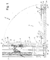
- Figure 1
- illustrates a lateral elevation of a preferred embodiment of equipment for stowing and handling according to the present invention in two different respective working positions;
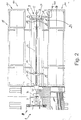
- Figure 2
- is a plan view, with some parts removed for reasons of clarity, of a detail of the equipment shown in Figure 1;
- Figure 3
- is a lateral elevation of the equipment shown in Figure 1; and
- Figures 4 and 5
- illustrate the equipment shown in Figure 1 in another working condition.
- With reference to Figures 1 and 2, the
number 1 indicates a drilling plant, in its entirety, which is suitable for excavating boreholes (not illustrated). - The
drilling plant 1 comprises adrilling tower 3 and a driving head 4 for the screwing ofdrilling rods 5 or casing pipes 5a (Figures 4 and 5), and a quadrilateral articulated device, which is interposed between thetower 3 and the head 4, and is suitable not only for permitting the head 4 to slide along thetower 3, but also for permitting the movement of the head 4 itself from an operating working position, in which the head 4 is arranged on an upright A of the above-mentioned borehole, and a handling working position, in which the head 4 is arranged on an upright B of aservice well 7 which is laterally arranged to the borehole itself. - The
drilling plant 1 also comprisesequipment 8 for stowing and handling therods 5, which comprises in its turn acontrol unit 9 for moving therods 5 themselves suitable for moving therods 5 from and towards the service well 7, and for maintaining therods 5 at a determined height in relation to the service well 7 itself, or for arranging therods 5 inside the service well 7 in such a way that an operator can arranged the head 4 on therod 5. - The
equipment 8 also comprises two stowing stations S1 and S2 for stowing the rods arranged opposite thecontrol unit 9 for housing the provisioning semitrailer 10 of therods 5, and anunloading device 11 which is suitable for moving therods 5 themselves from the provisioning semitrailer 10 to thecontrol unit 9. As an alternative to the provisioning semitrailer 10, theequipment 8 can comprise two so-called "pipe racks" (noted but not illustrated), which can be arranged in the stations S1 and S2 in order to supply thecontrol unit 9 with therods 5. - The
control unit 9 for moving the rods is a pre-assembled control unit, which can be transported using the usual means of transport, and can be installed laterally to the service well 7 between the two stations S1 and S2, and comprising aplatform 12 presenting a main longitudinal axis C which is arranged incidentally and transversally to the uprights A and B, and atiltable loader 13 which is rotatably mounted in relation to theplatform 12 itself in order to rotate around a tilting axis D which is arranged transversally to the axis C, and is defined by aconnecting hinge 14 of theloader 13 to theplatform 12. - The
loader 13 comprises asupport beam 15 which is hinged to a base of thehinge 14, acarriage 16 which is slidingly mounted along thebeam 15, twobrackets longitudinal seat 19 parallel to thebeam 15 itself, and atelescopic actuator device 20 connected to thebeam 15 and to theplatform 12 in order to rotate thebeam 15 and theseat 19 between a flat working position, in which theseat 19 is arranged parallel to the C axis in order to receive arelative rod 5, and a raised working position, in which theseat 19 is arranged parallel to the B axis in order to arrange therod 5 itself onto the upright B of the service well 7. - The
carriage 16 is part of apositioning device 21, which is suitable for positioning therods 5 in a set-up working position in order to permit the withdrawal of the driving head 4, and comprises, for each of thebrackets clamps 22 which can move from and towards theseat 19 in order to clamp onto arod 5 arranged in theseat 19 itself. In particular, thebracket 18 is a mobile bracket supported by thecarriage 16, while thebracket 17 is a fixed bracket which is directly supported by thebeam 15, and therespective clamps 22 present a clamping movement onto theseat 19 in order to prevent therod 5 escaping from theseat 19 itself, and to permit therod 5 to slide along the C axis by means of rollers (noted but not illustrated) on a axis which is transverse to the C axis itself. - Finally, the
control unit 9 comprises a stabilising andlevelling device 23 which is suitable for stabilising and levelling theplatform 12 in both a longitudinal and a transverse direction, which in its turn comprises fourhydraulic hammers 24 arranged in correspondence to the respective corners of theplatform 12 itself, and an adjustingscrew 25 which is placed in front of thehinge 14. - The
device 23 is suitable for co-operating with theunloading device 11 in order to permit arod 5 to be coupled to theseat 19, saidrod 5 having been unloaded from the provisioning semitrailer 10 by means of theunloading device 11 itself. - As can be better seen in the illustration shown in Figure 3, the
unloading device 11 comprises, for each of thebrackets vertical pipes 26 arranged opposite therespective brackets pipe 27, which is supported by therelative pipes 26. Thedevice 11 is provided with two blocking elements 28 arranged at the respective opposite ends in order to block in a waiting position therods 5 provided from the stations S1, S2, and is also provided with two further blockingelements 29 arranged centrally to thepipe 27 itself in order to position arod 5 onto the upright of theseat 19. Thepipes 27 are moved synchronously in relation to each other by means of activating the relative hydraulic orpneumatic pipes 26, and they are tilted from and towards the stations S1 and S2 of thepipes 26 themselves in order to assist the movement of therods 5 from and towards theelements 29. - The
unloading device 11 also comprises fourstabilisers 30 for each provisioning semitrailer 10 itself in order to permit levelling in a longitudinal direction and tilting in a transverse direction in such a way as to assist the sliding of therods 5 loaded onto the provisioning semitrailers 10 itself towards theelements 29. In the previously mentioned case, in which the provisioning semitrailer 10 is replaced with "pipe racks", thedevice 11 comprises a tilting device of a well-known type, which is not illustrated, suitable for assisting the sliding of therods 5 loaded onto the "pipe rack" itself towards theelements 29. - Figures 4 and 5 refer to the situation in which casing pipes 5a, as well as
rods 5, have to be moved, and illustrate an unloading device lls which comprises, for each station S1 and S2, two telescopic vertical pipes 26s and two horizontal pipes 27s installed on each provisioning semitrailers 10. The head 4 for therods 5 is replaced by a head 4a for the pipes 5a, and it can be seen from the illustration in Figure 4 that there are many advantages as a result of being able to work on the heads 4 and 4a at a height equal to the handling height when faced with the necessity of hooking therods 5 and the pipes 5a. - In use, the
platform 12 is taken to the excavation site by means of normal, well-known types of means of transport, and once theplatform 12 has been laterally positioned to the service well 7 with the relative C axis orientated transversally to the uprights A and B, the two stations S1 and S2 are engaged by one or two provisioning semitrailer 10, which, as illustrated in Figure 2, move and/or stow thedrilling rods 5 or, alternatively, casing pipes of a well-known type which are not illustrated. - At this point, the
unloading device 11 positions thepipes 27 at a height which substantially corresponds to the height of the upper edge of the side panel of one of the two provisioning semitrailer 10, while the stabilisers 30, after having levelled each provisioning semitrailer 10, tilt the provisioning semitrailer 10 itself from the side of thecontrol unit 9 in order to send therelative rods 5 to abut against the blocking elements 28. Once therod 5 is positioned against the element 28, thepipes 27 are tilted to permit therod 5 itself to slide towards the elements 28: thus, theelements 29 are disengaged from therod 5, which rolls towards the elements 28 themselves and is blocked by coming into contact with the elements 28 themselves, and when therod 5 is positioned on the upright of the C axis, which is to say directly above theseat 19, thepipes 27 are lowered to a point where therod 5 itself can be inserted inside theseat 19. - At this point, the
clamps 22 block therod 5 in theseat 19 in such a way as to prevent any movement of therod 5 itself in relation to theseat 19 itself, and, subsequently, thetelescopic actuator device 20 rotates thebeam 15 around thehinge 14 in such a way as to arrange therod 5 itself in its set-up position, which corresponds to a position in which alower end 31 of therod 5 itself remains substantially outside the service well7, which anupper end 32 of therod 5 is directly screwed onto the head 4. - Once the
rod 5 has been withdrawn from the head 4, theclamps 22 free therod 5 itself, and, while the quadrilateral articulated device 6 moves the head 4 and therod 5 onto the upright A, thedevice 21 moves theseat 19 back to its flat working position. - The operations which have just been described are carried out in the same way, but in reverse order, when a
rod 5 has to be unloaded from the head 4 in order to be stowed again in the station S1 or S2. - Instead, in the case that it is necessary to arrange the
end 32 inside the service well 7 in order to position theupper end 31 of therod 5 itself at a determined height that will permit the drilling plant operators to carry out ordinary operations related to hooking therods 5 to the elevators (not illustrated) below the head 4, thecarriage 16 is made to slide together with therelative bracket 18 in relation to thebeam 15, while therod 5, which is firmly blocked by theclamp 22 of thebracket 17, slides inside thebracket 17 by means of the above-mentioned rollers (noted but not illustrated) on an axis transverse to the C axis. - Obviously, the positioning height of the
rods 5 along the C axis, whether this relates to drilling rods or casing pipes, can be freely regulated by simply moving thecarriage 16 in relation to thebeam 15, and by maintaining the rod itself firmly inside thebracket 18. - It is obvious from the above description that the opportunity of arriving at an excavation site with
equipment 8 which is already assembled means that a considerable amount of time can be saved in terms of installation and that, furthermore, the opportunity of filling the two stations S1 and S2 with normal provisioning semitrailer 10 permits the availability of containers with a substantially infinite capacity as the empty provisioning semitrailer 10 can be replaced as and when necessary with full provisioning semitrailer 10, and also permits major flexibility in terms of the overall functioning of theequipment 8. - Furthermore, given that the position of each
rod 5 is substantially controlled starting from the provisioning semitrailers until it reaches its set-up position it is practically impossible for therod 5 itself to move accidentally and create a danger to the operators working on thedrilling plant 1.
Claims (10)
- Equipment (8) for stowing and handling rods (5) for drilling plants (1) comprising a service well (7) for lifting and placing the individual rods (5), and a control unit (9) for moving the rods (5) suitable for moving the rods (9) from and towards the service well (7) itself, and comprising tilting means (13) which can move between a flat working position and a raised working position in order to arrange the rods (5) on an upright (B) of the said service well (7), the equipment (8) being characterised by the fact that the said tilting means (13) are pre-assembled tiling means (13) which can be installed laterally to the service well (7), and comprise a support beam (15) which tilts around an axis of rotation (D), and positioning means (21) associated with the beam (15) itself in order to position each rod (5) in a set-up working position at least along the said upright (B).
- Equipment according to Claim 1, characterised by the fact that the said tilting means (13) comprise a platform (12) which can be installed laterally to the said service well (7), and a horizontal connecting hinge (14) between the platform (12) and the said support beam (15), the hinge (14) extending along the said axis of rotation (D).
- Equipment according to Claim 1 or 2, characterised by the fact that said positioning means (21) comprise blocking means (22) for blocking said rods (5) to said tilting means (13), and sliding means (16) which are slidingly supported along said support beam (15) in order to regulate, at least along the said upright (B), the said set-up working position.
- Equipment according to Claim 3, characterised by the fact that said blocking means (22) comprise a housing seat (19( for one of the said rods (5), the seat (19) being partially supported by said sliding means (16), and at least one clamping pincer (22) which can close onto a relative rod (5), and comprising a mobile clamp (22) which can move from and towards the said seat (19).
- Equipment according to Claim 3, characterised by the fact that the said blocking means (22) comprise a housing seat (19) for one of the said rods (5), the seat (19) being partially supported by said sliding means (16); and two camping pincers (22) which can close onto one of the relative said rods (5), and each comprising a respective mobile clamp which can move from and towards said seat (19).
- Equipment according to Claim 5, characterised by the fact that a first clamping pincer (22) of the said two clamping pincers (22) is integral to the said sliding means (16), and a second clamping pincer (22) of the said two clamping pincers (22) is integral to said support beam (15).
- Equipment according to any of the preceding Claims, characterised by the fact of comprising at least one service station (S1, S2) arranged laterally to said tilting means (13) and suitable for housing provisioning means (10) of the said rods (5).
- Equipment according to Claim 7, characterised by the fact of comprising two service stations (S1, S2) arranged opposite said tilting means (13).
- Equipment according to Claim 8, characterised by the fact of comprising unloading means (11) for unloading the rods (5) from each service station (S1, S2); the unloading means comprising two cross pipes (27) arranged above said seat (19), and tilting means (26) for synchronously tilting the cross pipes (27) themselves.
- Equipment according to any of the preceding Claims, characterised by the fact of comprising a driving head (4) which is mobile parallel to itself from and towards the said service well (7).
Applications Claiming Priority (2)
| Application Number | Priority Date | Filing Date | Title |
|---|---|---|---|
| IT1998TO000687A IT1303214B1 (en) | 1998-08-06 | 1998-08-06 | STORAGE AND MANEUVERING EQUIPMENT OF THE AUCTIONS FOR LEVELING SYSTEMS |
| ITTO980687 | 1998-08-06 |
Publications (2)
| Publication Number | Publication Date |
|---|---|
| EP0978628A2 true EP0978628A2 (en) | 2000-02-09 |
| EP0978628A3 EP0978628A3 (en) | 2000-06-28 |
Family
ID=11416982
Family Applications (1)
| Application Number | Title | Priority Date | Filing Date |
|---|---|---|---|
| EP99113660A Withdrawn EP0978628A3 (en) | 1998-08-06 | 1999-07-14 | Equipment for stowing and handling rods used in drilling rigs |
Country Status (2)
| Country | Link |
|---|---|
| EP (1) | EP0978628A3 (en) |
| IT (1) | IT1303214B1 (en) |
Cited By (3)
| Publication number | Priority date | Publication date | Assignee | Title |
|---|---|---|---|---|
| EP1158136A1 (en) * | 2000-05-23 | 2001-11-28 | SOILMEC S.p.A. | Equipment for stowing and handling drill pipes |
| CN112621709A (en) * | 2020-11-27 | 2021-04-09 | 中石化石油机械股份有限公司研究院 | Multifunctional walking track mechanism |
| CN113153183A (en) * | 2021-04-14 | 2021-07-23 | 四川宏华石油设备有限公司 | Lifting manipulator |
Citations (6)
| Publication number | Priority date | Publication date | Assignee | Title |
|---|---|---|---|---|
| FR2092611A1 (en) * | 1970-06-01 | 1972-01-28 | Snecma | |
| US3851770A (en) * | 1973-04-30 | 1974-12-03 | Moore L | Pivoted well drilling mast and separate tower |
| US4020909A (en) * | 1974-11-26 | 1977-05-03 | Antonin Airaudo | Portable earth drilling apparatus |
| GB2083106A (en) * | 1981-08-28 | 1982-03-17 | Boland Thomas | Apparatus for storing, and transferring drill stems to a drilling head |
| US4899832A (en) * | 1985-08-19 | 1990-02-13 | Bierscheid Jr Robert C | Modular well drilling apparatus and methods |
| EP0731251A2 (en) * | 1992-09-23 | 1996-09-11 | SOILMEC S.p.A. | A stowing and handling system for rods used in drilling rigs |
-
1998
- 1998-08-06 IT IT1998TO000687A patent/IT1303214B1/en active IP Right Grant
-
1999
- 1999-07-14 EP EP99113660A patent/EP0978628A3/en not_active Withdrawn
Patent Citations (6)
| Publication number | Priority date | Publication date | Assignee | Title |
|---|---|---|---|---|
| FR2092611A1 (en) * | 1970-06-01 | 1972-01-28 | Snecma | |
| US3851770A (en) * | 1973-04-30 | 1974-12-03 | Moore L | Pivoted well drilling mast and separate tower |
| US4020909A (en) * | 1974-11-26 | 1977-05-03 | Antonin Airaudo | Portable earth drilling apparatus |
| GB2083106A (en) * | 1981-08-28 | 1982-03-17 | Boland Thomas | Apparatus for storing, and transferring drill stems to a drilling head |
| US4899832A (en) * | 1985-08-19 | 1990-02-13 | Bierscheid Jr Robert C | Modular well drilling apparatus and methods |
| EP0731251A2 (en) * | 1992-09-23 | 1996-09-11 | SOILMEC S.p.A. | A stowing and handling system for rods used in drilling rigs |
Cited By (4)
| Publication number | Priority date | Publication date | Assignee | Title |
|---|---|---|---|---|
| EP1158136A1 (en) * | 2000-05-23 | 2001-11-28 | SOILMEC S.p.A. | Equipment for stowing and handling drill pipes |
| US6591904B2 (en) | 2000-05-23 | 2003-07-15 | Soilmec S.P.A. | Equipment for stowing and handling drill pipes |
| CN112621709A (en) * | 2020-11-27 | 2021-04-09 | 中石化石油机械股份有限公司研究院 | Multifunctional walking track mechanism |
| CN113153183A (en) * | 2021-04-14 | 2021-07-23 | 四川宏华石油设备有限公司 | Lifting manipulator |
Also Published As
| Publication number | Publication date |
|---|---|
| EP0978628A3 (en) | 2000-06-28 |
| ITTO980687A1 (en) | 2000-02-06 |
| IT1303214B1 (en) | 2000-11-02 |
| ITTO980687A0 (en) | 1998-08-06 |
Similar Documents
| Publication | Publication Date | Title |
|---|---|---|
| US4547110A (en) | Oil well drilling rig assembly and apparatus therefor | |
| US4969792A (en) | Truck supporting device | |
| US5807061A (en) | Linkage arrangement for a skid-steer loader | |
| US4019604A (en) | Elevating platform apparatus | |
| CA1199627A (en) | Pipe pickup and laydown machine | |
| US7568533B2 (en) | Pipehandler | |
| US4236861A (en) | Scissors lift with pipe handler | |
| US20090232634A1 (en) | Method and a device for lifting and rotating a massive container | |
| US5192178A (en) | Extensible discharge chute assembly | |
| US4022026A (en) | Safety shield attachment | |
| US3954189A (en) | Material handling apparatus | |
| EP0978628A2 (en) | Equipment for stowing and handling rods used in drilling rigs | |
| CN114906748A (en) | Unit hydraulic support transfer robot | |
| US5931043A (en) | Multi-modular vehicle repair system | |
| WO2005077711A1 (en) | Pipe handling apparatus | |
| CA1252067A (en) | Apparatus for container handling | |
| CN113650550B (en) | Vehicle-mounted transportation device | |
| US20060101782A1 (en) | Material handler | |
| CN208747175U (en) | A kind of excavation stand hoisting mechanism | |
| US3481440A (en) | Power means for a cement discharge chute | |
| EP1176283B1 (en) | Mobile drilling unit | |
| US2830720A (en) | Automatic bucket dumping hoist | |
| US3697044A (en) | Camper unit lifting device | |
| US5076749A (en) | Material handling platform for material transport vehicle | |
| CN115123981B (en) | Working bucket assembly and working machine |
Legal Events
| Date | Code | Title | Description |
|---|---|---|---|
| PUAI | Public reference made under article 153(3) epc to a published international application that has entered the european phase |
Free format text: ORIGINAL CODE: 0009012 |
|
| AK | Designated contracting states |
Kind code of ref document: A2 Designated state(s): AT BE CH CY DE DK ES FI FR GB GR IE IT LI LU MC NL PT SE |
|
| AX | Request for extension of the european patent |
Free format text: AL;LT;LV;MK;RO;SI |
|
| PUAL | Search report despatched |
Free format text: ORIGINAL CODE: 0009013 |
|
| AK | Designated contracting states |
Kind code of ref document: A3 Designated state(s): AT BE CH CY DE DK ES FI FR GB GR IE IT LI LU MC NL PT SE |
|
| AX | Request for extension of the european patent |
Free format text: AL;LT;LV;MK;RO;SI |
|
| AKX | Designation fees paid | ||
| STAA | Information on the status of an ep patent application or granted ep patent |
Free format text: STATUS: THE APPLICATION IS DEEMED TO BE WITHDRAWN |
|
| 18D | Application deemed to be withdrawn |
Effective date: 20001229 |
|
| REG | Reference to a national code |
Ref country code: DE Ref legal event code: 8566 |