EP0978902A2 - Crimp-on connector for flat cable - Google Patents
Crimp-on connector for flat cable Download PDFInfo
- Publication number
- EP0978902A2 EP0978902A2 EP99115539A EP99115539A EP0978902A2 EP 0978902 A2 EP0978902 A2 EP 0978902A2 EP 99115539 A EP99115539 A EP 99115539A EP 99115539 A EP99115539 A EP 99115539A EP 0978902 A2 EP0978902 A2 EP 0978902A2
- Authority
- EP
- European Patent Office
- Prior art keywords
- crimp connector
- flat
- flat cable
- contact elements
- carrier element
- Prior art date
- Legal status (The legal status is an assumption and is not a legal conclusion. Google has not performed a legal analysis and makes no representation as to the accuracy of the status listed.)
- Withdrawn
Links
Images


Classifications
-
- H—ELECTRICITY
- H01—ELECTRIC ELEMENTS
- H01R—ELECTRICALLY-CONDUCTIVE CONNECTIONS; STRUCTURAL ASSOCIATIONS OF A PLURALITY OF MUTUALLY-INSULATED ELECTRICAL CONNECTING ELEMENTS; COUPLING DEVICES; CURRENT COLLECTORS
- H01R12/00—Structural associations of a plurality of mutually-insulated electrical connecting elements, specially adapted for printed circuits, e.g. printed circuit boards [PCB], flat or ribbon cables, or like generally planar structures, e.g. terminal strips, terminal blocks; Coupling devices specially adapted for printed circuits, flat or ribbon cables, or like generally planar structures; Terminals specially adapted for contact with, or insertion into, printed circuits, flat or ribbon cables, or like generally planar structures
- H01R12/50—Fixed connections
- H01R12/59—Fixed connections for flexible printed circuits, flat or ribbon cables or like structures
- H01R12/61—Fixed connections for flexible printed circuits, flat or ribbon cables or like structures connecting to flexible printed circuits, flat or ribbon cables or like structures
- H01R12/613—Fixed connections for flexible printed circuits, flat or ribbon cables or like structures connecting to flexible printed circuits, flat or ribbon cables or like structures by means of interconnecting elements
-
- H—ELECTRICITY
- H01—ELECTRIC ELEMENTS
- H01R—ELECTRICALLY-CONDUCTIVE CONNECTIONS; STRUCTURAL ASSOCIATIONS OF A PLURALITY OF MUTUALLY-INSULATED ELECTRICAL CONNECTING ELEMENTS; COUPLING DEVICES; CURRENT COLLECTORS
- H01R12/00—Structural associations of a plurality of mutually-insulated electrical connecting elements, specially adapted for printed circuits, e.g. printed circuit boards [PCB], flat or ribbon cables, or like generally planar structures, e.g. terminal strips, terminal blocks; Coupling devices specially adapted for printed circuits, flat or ribbon cables, or like generally planar structures; Terminals specially adapted for contact with, or insertion into, printed circuits, flat or ribbon cables, or like generally planar structures
- H01R12/50—Fixed connections
- H01R12/59—Fixed connections for flexible printed circuits, flat or ribbon cables or like structures
- H01R12/65—Fixed connections for flexible printed circuits, flat or ribbon cables or like structures characterised by the terminal
- H01R12/69—Fixed connections for flexible printed circuits, flat or ribbon cables or like structures characterised by the terminal deformable terminals, e.g. crimping terminals
Definitions
- the present invention relates to a crimp connector for Flat cables and a method for connecting two Flat cables using such a crimp connector.
- the crimp connector comprises therefore a carrier element for two flat cables, which is essentially transverse to the longitudinal extension of the flat lines to be connected extends, at least one contact element, which is essentially longitudinal of the flat cables and which extends to the carrier element is attached, with one conductor track of the flat cables an electrically conductive contact element is provided , and wherein a plurality of holding members on each contact element is provided, which is permanent with the flat cables can be brought into engagement.
- crimp connector 1 shows a crimp connector 1 in plan view and shown in perspective.
- a carrier element 2 is arranged, which is transverse to a
- a plurality of contact elements 3 runs in this embodiment are provided in triplicate.
- the three contact elements 3 are only given as examples and with the crimp connector 1 according to the invention any number of conductor tracks 10 (FIG. 3) one Flat line 11 or 12 are connected. In the shown In the exemplary embodiment, there are three conductor tracks 10 connected to two to be connected flat lines 11 and 12, and the can be connected by one contact element 3 each.
- the crimp connector 1 comprises the carrier element 2 made of an electrically insulating material, for example Plastic, the carrier element 2 a substantially cuboid shape, which has a clear longitudinal extension having.
- the carrier element 2 extends in Use across a flat cable 11 or 12 (see Figure 6) so that the contact elements arranged on the carrier element 2 3, which is essentially parallel to the flat cable 11 or 12 run perpendicular to the carrier element 2 are arranged.
- the contact elements 3 are on the underside ( Figure 2) of the support member 2 attached.
- the attachment can already in one injection molding of the carrier element 2 Operation take place, in which case the contact elements 3 in the Injection mold are to be arranged, or else by other Known fastening devices 7 take place.
- the contact elements 3 are electrically conductive parts, for example from sheet metal, their shape by punching and bending is preserved.
- On the elongated, essentially flat Contact elements 3 are holding members 4 on the one hand provided, and on the other hand, cutting devices 5 formed are.
- the holding members 4 are substantially triangular in shape Jagged or claws formed on the long sides of the contact elements 3, spaced apart from one another, are provided are.
- the holding members 4 engage in the assembly of the crimp connector into the openings 8 of the flat cable 11 or 12 on.
- the holding members 4 are almost at right angles from the Main plane of the contact elements 3 bent and for reasons an easier insertion into the openings 8 with a rounded tip.
- the cutting devices 5 are in the form of sharp-edged Tips that are preferably punched out triangular and after are bent at the top.
- the cutting devices 5 are lying in the middle of the contact elements 3, to each other spaced, preferably provided several times.
- the peaks of the cutting devices 5 penetrate during the assembly of the Crimpconnectors the flat cable 11 or 12 and the one on it located conductor track 10 ( Figure 5). This will make it a safe one Contact between the conductor track 10 and the contact element 3 guaranteed.
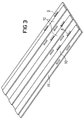
- the flat cable 11 ( Figure 3, 4 and 5) is at the end where the crimp connector 1 is to be assembled, cut cleanly and punched with a suitable tool. Advantageously can do this in one operation with one tool respectively.
- the openings 8 are at one end in the Flat cable introduced that the end of the flat cable the carrier element 2 of the crimp connector 1 is flush and that the holding members 4 of the crimp connector 1, the openings 8th reach through, as shown in Figure 5.
- the support element 2 thus serves as a stop for the flat cable and thus as a positioning aid between flat cable (s) and crimp connector 1.
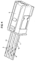
- a replacement connector 9 is mounted ( Figures 4 and 5).
- the assembly of the replacement connector 9 on the flat cable 11 can, since outside a vehicle possible, preferably by welding respectively. Crimping can already take place in this step of the crimp connector 1 on the flat cable 11.
- the crimping is done.
- the holding members 4 bent and preferably also with the conductor tracks 10 engaged.
- the cutting devices 5 are also bent over the flat cables 11 and hold 12 securely.
- the crimp connection is strapped with an insulating tape, after connecting the flat cables 11, 12 an electrical Isolate the crimp connector 1 from the outside by means of Insulating tape or a separate housing, which preferably consists of plastic.
- the total thickness of the flat cables 11 and 12 is only a few 1/10 mm, the pitch of the conductor tracks 10 is usually 2.54 mm. As a result of this very small Dimensions is an extremely precise attachment of the crimp connector 1 essential.
- the present invention solves this technical problem Help of the previously introduced on the flat cables 11 and 12 Openings 8, which allow secure positioning.
Abstract
Description
Die vorliegende Erfindung betrifft einen Crimpverbinder für Flachleitungen sowie ein Verfahren zum Verbinden zweier Flachleitungen mittels eines solchen Crimpverbinders.The present invention relates to a crimp connector for Flat cables and a method for connecting two Flat cables using such a crimp connector.
Eine herkömmliche Verkabelung in beispielsweise einem KFZ erfolgt mit Rundleitern, wobei die hierfür erforderlichen Kabelquerschnitte und die zugehörigen Steckverbindungen einen großen Bauraum erfordern. Aus diesem Grund wird im KFZ-Bereich auch über den Einsatz von Flachleitungen diskutiert, wobei dann die elektrischen Steckverbindungen an der Flachleitung mittels einer Widerstandsschweißung kontaktiert werden.Conventional cabling is carried out in a motor vehicle, for example with round conductors, the cable cross-sections required for this and the associated connectors one require large installation space. For this reason, in the automotive sector also discussed the use of flat cables, then the electrical connectors on the flat cable be contacted by means of resistance welding.
Ein solches Verfahren zum elektrischen Verbinden eines Steckverbinders mit einer Flachleitung ist in der EP-0,816,003 A2 beschrieben.Such a method for electrically connecting a connector with a flat cable is in EP-0,816,003 A2 described.
Nicht nur im KFZ-Bereich muß im Falle eines Defekts die Flachleitung bzw. die Steckverbindung ausgetauscht werden. Das Widerstandsschweiß-Verfahren ist für solche Reparaturfälle zu aufwendig. Die Schweißeinrichtung ist unhandlich und zu teuer.In the event of a defect, the Flat cable or the plug connection can be replaced. The resistance welding process is for such repair cases too expensive. The welding device is unwieldy and too expensive.
Demgegenüber ist es die Aufgabe der vorliegenden Erfindung, einen Crimpverbinder für Flachleitungen zu schaffen, der ein einfaches und kostengünstiges Austauschen von Flachleitungen und Steckverbindern erlaubt.In contrast, it is the object of the present invention to create a crimp connector for flat cables, the one simple and inexpensive replacement of flat cables and connectors allowed.
Diese Aufgabe wird durch einen Crimpverbinder gelöst, wie er im Patentanspruch 1 angegeben ist.This task is solved by a crimp connector like the one he uses is specified in claim 1.
Vorteilhafte Weiterbildungen eines solchen Crimpverbinders ergeben sich aus den Unteransprüchen. Advantageous further developments of such a crimp connector result from the subclaims.
Ein besonders vorteilhaftes Verfahren zum Verbinden zweier
Flachleitungen, wie es beispeilsweise im KFZ-Bereich bei Reparaturen
einsetzbar ist, ist gemäß Patentanspruch 10 vorgeschlagen.A particularly advantageous method for connecting two
Flat cables, as is the case, for example, in the automotive sector for repairs
can be used, is proposed according to
In Übereinstimmung mit dem Patentanspruch 1 umfaßt der Crimpverbinder für zwei Flachleitungen daher ein Trägerelement, welches sich im wesentlichen quer zu der Längserstreckung der zu verbindenden Flachleitungen erstreckt, zumindest ein Kontaktelement, welches sich im wesentlichen in Längsrichtung der Flachleitungen erstreckt und welches an dem Trägerelement befestigt ist, wobei für jeweils eine Leiterbahn der Flachleitungen ein, elektrisch leitendes Kontaktelement vorgesehen ist, und wobei an jedem Kontaktelement eine Mehrzahl von Haltegliedern vorgesehen ist, die mit den Flachleitungen dauerhaft in Eingriff bringbar sind.In accordance with claim 1, the crimp connector comprises therefore a carrier element for two flat cables, which is essentially transverse to the longitudinal extension of the flat lines to be connected extends, at least one contact element, which is essentially longitudinal of the flat cables and which extends to the carrier element is attached, with one conductor track of the flat cables an electrically conductive contact element is provided , and wherein a plurality of holding members on each contact element is provided, which is permanent with the flat cables can be brought into engagement.
Die vorliegende Erfindung wird im folgenden anhand einer Ausführungsform ausführlich dargestellt, wobei auf die zugehörigen Zeichnungen bezug genommen wird.The present invention will hereinafter be described in one embodiment shown in detail, referring to the associated Reference is made to drawings.
Es zeigen in den Zeichnungen:
- Fig. 1
- eine perspektivische Ansicht eines Crimpverbinders nach der vorliegenden Erfindung von oben;
- Fig. 2
- eine perspektivische Ansicht eines Crimpverbinders nach der vorliegenden Erfindung von unten;
- Fig. 3
- eine perspektivische Ansicht einer abgeschnittenen und gelochten Flachleitung;
- Fig. 4
- eine perspektivische Ansicht der Flachleitung nach
der
Figur 3, wobei an einem Ende ein Ersatzstecker montiert ist; - Fig. 5
- eine perspektivische Ansicht der Flachleitung nach
der
Figur 3 und 4, wobei an dem anderen Ende der Flachleitung der Crimpverbinder angeordnet ist, wobei Schneideinrichtungen die Leiterbahnen durchdringen; - Fig. 6
- eine perspektivische Ansicht der Crimpverbindung, wobei die Halteglieder und die Schneideinrichtungen umgebogen sind; und
- Fig. 7
- eine vergrößerte Darstellung der Ansicht nach der
Figur 6.
- Fig. 1
- a perspective view of a crimp connector according to the present invention from above;
- Fig. 2
- a bottom perspective view of a crimp connector according to the present invention;
- Fig. 3
- a perspective view of a cut and perforated flat cable;
- Fig. 4
- 3 shows a perspective view of the flat cable according to FIG. 3, a replacement plug being mounted at one end;
- Fig. 5
- 3 shows a perspective view of the flat cable according to FIGS. 3 and 4, the crimp connector being arranged at the other end of the flat cable, with cutting devices penetrating the conductor tracks;
- Fig. 6
- a perspective view of the crimp connection, wherein the holding members and the cutting devices are bent; and
- Fig. 7
- an enlarged view of the view of Figure 6.
Unter Bezugnahme auf die Figuren 1 bis 7 wird im folgenden ein erfindungsgemäßer Crimpverbinder sowie die Verwendung eines solchen Crimpverbinders erläutert.With reference to Figures 1 to 7, the following an inventive crimp connector and the use of a such crimp connector explained.
In der Figur 1 ist ein Crimpverbinder 1 in der Draufsicht und
perspektivisch dargestellt. In der Mitte des Crimpverbinders
1 ist ein Trägerelement 2 angeordnet, welches quer zu einer
Mehrzahl von Kontaktelementen 3 verläuft, die bei dieser Ausführungsform
dreifach vorgesehen sind.1 shows a crimp connector 1 in plan view and
shown in perspective. In the middle of the crimp connector
1, a
Die drei Kontaktelemente 3 sind lediglich beispielhaft angegeben
und es kann mit dem erfindungsgemäßen Crimpverbinder 1
jede beliebige Anzahl von Leiterbahnen 10 (Figur 3) einer
Flachleitung 11 oder 12 verbunden werden. In dem gezeigten
Ausführungsbeispiel sind es drei Leiterbahnen 10, die an zwei
zu verbindenden Flachleitungen 11 und 12 vorliegen, und die
durch jeweils ein Kontaktelement 3 verbunden werden.The three
Der Crimpverbinder 1 nach der Figur 1 umfaßt das Trägerelement
2 aus einem elektrisch isolierenden Material, zum Beispiel
Kunststoff, wobei das Trägerelement 2 eine im wesentlichen
quaderförmige Gestalt hat, die eine eindeutige Längserstreckung
aufweist. Das Trägerelement 2 erstreckt sich im
Einsatz quer zu einer Flachleitung 11 oder 12 (siehe Figur 6)
so daß die an dem Trägerelement 2 angeordneten Kontaktelemente
3, die im wesentlichen parallel zu der Flachleitung 11
oder 12 verlaufen, senkrecht gegenüber dem Trägerelement 2
angeordnet sind. Die Kontaktelemente 3 sind auf der Unterseite
(Figur 2) des Trägerelementes 2 befestigt. Die Befestigung
kann bereits beim Spritzgießen des Trägerelementes 2 in einem
Arbeitsgang erfolgen, wobei dann die Kontaktelemente 3 in der
Spritzgießform anzuordnen sind, oder aber kann durch sonstige
bekannte Befestigungseinrichtungen 7 erfolgen.The crimp connector 1 according to FIG. 1 comprises the
Auf der Oberseite (Figur 1) des Trägerelementes 2 sind Kerben
6 vorgesehen, die sich zwischen den Kontaktelementen 3 erstrecken.
Vorzugsweise können diese Kerben 6 auch auf der Unterseite
(Figur 2) vorgesehen werden, um ein Abbrechen des
Trägerelementes 2 an dieser Stelle zu erleichtern.There are notches on the upper side (FIG. 1) of the
Die Kontaktelemente 3 sind elektrisch leitende Teile, beispielsweise
aus Blech, deren Form durch Stanzen und Biegen
erhalten ist. An den länglichen, im wesentlichen flach ausgebildeten
Kontaktelementen 3 sind einerseits Halteglieder 4
vorgesehen, sowie andererseits Schneideinrichtungen 5 ausgebildet
sind.The
Die Halteglieder 4 sind in Form von im wesentlichen dreieckigen
Zacken bzw. Krallen ausgebildet, die an den Längsseiten
der Kontaktelemente 3, zueinander beabstandet, vorgesehen
sind. Die Halteglieder 4 greifen bei der Montage des Crimpverbinders
in die Öffnungen 8 der Flachleitung 11 oder 12
ein. Die Halteglieder 4 sind nahezu im rechten Winkel von der
Hauptebene der Kontaktelemente 3 abgebogen und aus Gründen
einer einfacheren Einführbarkeit in die Öffnungen 8 mit einer
abgerundeten Spitze versehen.The
Die Schneideinrichtungen 5 sind in Form von scharfkantigen
Spitzen, die vorzugsweise dreieckförmig ausgestanzt und nach
oben gebogen sind, ausgebildet. Die Schneideinrichtungen 5
sind in der Mitte der Kontaktelemente 3 liegend, zueinander
beabstandet, vorzugsweise mehrfach vorgesehen. Die Spitzen
der Schneideinrichtungen 5 durchdringen bei der Montage des
Crimpverbinders die Flachleitung 11 oder 12 und die darauf
befindliche Leiterbahn 10 (Figur 5). Hierdurch wird eine sichere
Kontaktierung zwischen der Leiterbahn 10 und dem Kontaktelement
3 gewährleistet.The
Je nach Anzahl der Leiterbahnen 10 einer Flachleitung 11 oder
12 kann von einem Crimpverbinder 1, der beispielsweise zehn
oder mehr Kontaktelemente 3 trägt, eine geeignete Anzahl von
Kontaktelementen 3 abgebrochen werden. Die Kerben 6 erlauben
und erleichtern das zerstörungsfreie Abtrennen einer bestimmten
Anzahl von Kontaktelementen 3. Im gezeigten Beispiel werden
zwei Flachleitungen 11 und 12 mit jeweils drei Leiterbahnen
10 miteinander verbunden, so daß an dem Trägerelement 2
drei Kontaktelemente 3 erforderlich sind.Depending on the number of
Die Flachleitung 11 (Figur 3, 4 und 5) wird an dem Ende, an
dem der Crimpverbinder 1 montiert werden soll, sauber abgeschnitten
und mit einem geeigneten Werkzeug gelocht. Vorteilhafterweise
kann dies in einem Arbeitsgang mit einem Werkzeug
erfolgen. Die Öffnungen 8 werden an einem Ende so in die
Flachleitung eingebracht, daß das Ende der Flachleitung an
dem Trägerelement 2 des Crimpverbinders 1 bündig anliegt und
daß die Halteglieder 4 des Crimpverbinders 1 die Öffnungen 8
durchgreifen, wie es in der Figur 5 gezeigt ist. Das Trägerelement
2 dient also als Anschlag für die Flachleitung und somit
als Positionierhilfe zwischen Flachleitung(en) und Crimpverbinder
1.The flat cable 11 (Figure 3, 4 and 5) is at the end
where the crimp connector 1 is to be assembled, cut cleanly
and punched with a suitable tool. Advantageously
can do this in one operation with one tool
respectively. The
Am anderen freien Ende der Flachleitung 11 wird beispielsweise
ein Ersatzstecker 9 montiert (Figuren 4 und 5). Die Montage
des Ersatzsteckers 9 an der Flachleitung 11 kann, da außerhalb
eines KFZ möglich, vorzugsweise mittels Verschweißen
erfolgen. Bei diesem Arbeitsschritt kann bereits das Vercrimpen
des Crimpverbinders 1 an der Flachleitung 11 erfolgen. At the other free end of the
Das so konfektionierte Ersatz- bzw. Verbindungs-Flachleitungsstück
der Flachleitung 11 wird an der Flachleitung 12
montiert bzw. mit dieser verbunden, indem das freie Ende der
Flachleitung 12 ebenfalls abgeschnitten und gelocht wird, sowie
es in die zweite Hälte des Crimpverbinders 1 eingelegt
wird, so daß die dort vorhandenen Halteglieder 4 in die entsprechenden
Öffnungen eingreifen (Figur 6).The replacement or connection flat cable piece assembled in this way
the
Nach der korrekten Positionierung bzw. Ausrichtung der beiden
Flachleitungen 11 und 12 am Crimpverbinder 1 kann mittels eines
geeigneten Werkzeuges, beispielsweise einer Handzange,
das Vercrimpen erfolgen. Beim Vercrimpen werden die Spitzen
der Halteglieder 4 umgebogen und vorzugsweise ebenfalls mit
den Leiterbahnen 10 in Eingriff gebracht. Die Schneideinrichtungen
5 werden ebenfalls umgebogen, um die Flachleitungen 11
und 12 sicher fest zu halten.After the correct positioning or alignment of the two
In einem abschließenden, nicht dargestellten Arbeitsgang kann
die Crimpverbindung mit einem Isolierband umbändert werden,
wobei nach dem Verbinden der Flachleitungen 11, 12 eine elektrische
Isolierung des Crimpverbinders 1 nach außen mittels
Isolierband oder einem gesonderten Umgehäuse erfolgt, welches
vorzugsweise aus Kunststoff besteht.In a final operation, not shown, can
the crimp connection is strapped with an insulating tape,
after connecting the
Die gesamte Dicke der Flachleitungen 11 und 12 beträgt lediglich
wenige 1/10 mm, wobei die Teilung der Leiterbahnen 10
üblicherweise 2,54 mm beträgt. Infolge dieser sehr kleinen
Abmessungen ist eine äußerst genaue Anbringung des Crimpverbinders
1 unumgänglich.The total thickness of the
Die vorliegende Erfindung löst dieses technische Problem mit
Hilfe der an den Flachleitungen 11 und 12 vorher einzubringenden
Öffnungen 8, die eine sichere Positionierung erlauben.The present invention solves this technical problem
Help of the previously introduced on the
Das erfindungsgemäße Verfahren zum Verbinden zweier Flachleitungen
11 und 12 ergibt sich bereits aus der oben stehenden
Beschreibung des Crimpverbinders 1 an sich und dessen Anordnung
an den gezeigten Flachleitungen.The inventive method for connecting two
Claims (15)
wobei an jedem Kontaktelement (3) zumindest eine Schneideinrichtung (5) vorgesehen ist, die die Leiterbahn (10) der Flachleitung (11, 12) durchdringt.Crimp connector according to claim 1,
at least one cutting device (5) is provided on each contact element (3) and penetrates the conductor track (10) of the flat cable (11, 12).
wobei die Schneideinrichtung (5) in Form einer durch Stanzbiegen im wesentlichen senkrecht zum Kontaktelement (3) verlaufenden scharfkantigen Schneidkralle ausgebildet ist.Crimp connector according to claim 2,
wherein the cutting device (5) is designed in the form of a sharp-edged cutting claw which runs essentially perpendicular to the contact element (3) by stamping bending.
wobei das Trägerelement (2) als im wesentlichen quaderförmiges Bauteil vorliegt, an dessen Außenkanten die Flachleitungen (11, 12) ausrichtbar sind.Crimp connector according to one of claims 1 to 3,
the carrier element (2) being present as a substantially cuboid component, on the outer edges of which the flat lines (11, 12) can be aligned.
wobei das Trägerelement (2) eine Mehrzahl von Kontaktelementen (3) trägt, die parallel nebeneinanderliegend angeordnet sind. Crimp connector according to one of claims 1 to 4,
wherein the carrier element (2) carries a plurality of contact elements (3) which are arranged in parallel next to one another.
wobei das Trägerelement (2) eine Mehrzahl von Kontaktelementen (3) trägt, die parallel nebeneinanderliegend angeordnet sind, und wobei zwischen den Kontaktelementen (3) am Trägerelement (2) jeweils zumindest eine Kerbe (6) ausgebildet ist, die ein werkzeugloses Abtrennen einer vorbestimmten Anzahl von Kontaktelementen (3) erlaubt.Crimp connector according to one of claims 1 to 4,
wherein the carrier element (2) carries a plurality of contact elements (3), which are arranged in parallel next to each other, and wherein at least one notch (6) is formed between the contact elements (3) on the carrier element (2), which a tool-free separation of a predetermined Number of contact elements (3) allowed.
wobei das Trägerelement (2) aus einem elektrisch isolierenden Material, vorzugsweise Kunststoff besteht.Crimp connector according to one of claims 1 to 6,
wherein the carrier element (2) consists of an electrically insulating material, preferably plastic.
wobei die Teilung der Kontaktelemente (3) am Trägerelement (2) im wesentlichen 2,54 mm beträgt.Crimp connector according to one of claims 1 to 7,
the pitch of the contact elements (3) on the carrier element (2) being essentially 2.54 mm.
wobei die Halteglieder (4) in Form von im wesentlichen dreieckförmigen Abbiegungen vorliegen, die nahezu senkrecht zu der Ebene der Kontaktelemente (3) verlaufen.Crimp connector according to one of claims 1 to 8,
the holding members (4) being in the form of essentially triangular bends which run almost perpendicular to the plane of the contact elements (3).
wobei nach dem Verbinden der Flachleitungen (11, 12) eine elektrische Isolierung des Crimpverbinders (1) nach außen mittels Isolierband erfolgt.A method according to claim 10,
after connecting the flat cables (11, 12), the crimp connector (1) is electrically insulated from the outside by means of insulating tape.
wobei vor dem Verbinden der Flachleitungen (11, 12) mittels des Crimpverbinders (1) eine geeignete Anzahl von Kontaktelementen (3) abgetrennt wird.Method according to one of claims 10 or 11,
a suitable number of contact elements (3) being disconnected before the flat lines (11, 12) are connected by means of the crimp connector (1).
wobei vorzugsweise in einem Kraftfahrzeug zwei Flachleitungen (11, 12) miteinander verbindbar sind.Method according to one of claims 10 to 13,
wherein two flat cables (11, 12) can preferably be connected to one another in a motor vehicle.
wobei nach dem Verbinden der Flachleitungen (11, 12) eine elektrische Isolierung des Crimpverbinders (1) nach außen mittels einem gesonderten Umgehäuse erfolgt, welches vorzugsweise aus Kunststoff besteht.A method according to claim 10,
after connecting the flat cables (11, 12), the crimp connector (1) is electrically insulated from the outside by means of a separate housing, which is preferably made of plastic.
Applications Claiming Priority (2)
| Application Number | Priority Date | Filing Date | Title |
|---|---|---|---|
| DE19835022 | 1998-08-03 | ||
| DE19835022 | 1998-08-03 |
Publications (2)
| Publication Number | Publication Date |
|---|---|
| EP0978902A2 true EP0978902A2 (en) | 2000-02-09 |
| EP0978902A3 EP0978902A3 (en) | 2001-02-14 |
Family
ID=7876305
Family Applications (1)
| Application Number | Title | Priority Date | Filing Date |
|---|---|---|---|
| EP99115539A Withdrawn EP0978902A3 (en) | 1998-08-03 | 1999-08-02 | Crimp-on connector for flat cable |
Country Status (1)
| Country | Link |
|---|---|
| EP (1) | EP0978902A3 (en) |
Cited By (2)
| Publication number | Priority date | Publication date | Assignee | Title |
|---|---|---|---|---|
| DE10161857A1 (en) * | 2001-12-17 | 2003-07-10 | Wezag Gmbh | Device for connecting contact(s) to conducting track in flat cable has replaceable flap positioner on carrier, block movable on frame on which carrier is elastically deflectably mounted |
| DE102004061425A1 (en) * | 2004-12-21 | 2006-07-06 | Tyco Electronics Amp Gmbh | Electrical connector for attachment of electrical conductor to flexible flat cable, has base section to which conductive strip of flat cable is electrically connected elastically over at least one contact area |
Citations (4)
| Publication number | Priority date | Publication date | Assignee | Title |
|---|---|---|---|---|
| US3960430A (en) * | 1974-10-29 | 1976-06-01 | Amp Incorporated | Flat wiring system and crimped connection |
| EP0286422A2 (en) * | 1987-04-10 | 1988-10-12 | E.I. Du Pont De Nemours And Company | Electrical connector terminal for a flexible printed circuit board |
| US4784623A (en) * | 1987-04-03 | 1988-11-15 | Amp Incorporated | Mass terminable flat flexible cable to pin connector |
| EP0555964A2 (en) * | 1992-02-13 | 1993-08-18 | The Whitaker Corporation | Mid-cable electrical termination |
-
1999
- 1999-08-02 EP EP99115539A patent/EP0978902A3/en not_active Withdrawn
Patent Citations (4)
| Publication number | Priority date | Publication date | Assignee | Title |
|---|---|---|---|---|
| US3960430A (en) * | 1974-10-29 | 1976-06-01 | Amp Incorporated | Flat wiring system and crimped connection |
| US4784623A (en) * | 1987-04-03 | 1988-11-15 | Amp Incorporated | Mass terminable flat flexible cable to pin connector |
| EP0286422A2 (en) * | 1987-04-10 | 1988-10-12 | E.I. Du Pont De Nemours And Company | Electrical connector terminal for a flexible printed circuit board |
| EP0555964A2 (en) * | 1992-02-13 | 1993-08-18 | The Whitaker Corporation | Mid-cable electrical termination |
Cited By (3)
| Publication number | Priority date | Publication date | Assignee | Title |
|---|---|---|---|---|
| DE10161857A1 (en) * | 2001-12-17 | 2003-07-10 | Wezag Gmbh | Device for connecting contact(s) to conducting track in flat cable has replaceable flap positioner on carrier, block movable on frame on which carrier is elastically deflectably mounted |
| DE10161857C2 (en) * | 2001-12-17 | 2003-10-23 | Wezag Gmbh | Device for the conductive connection of at least one contact on a conductor track in a single or multi-core ribbon cable |
| DE102004061425A1 (en) * | 2004-12-21 | 2006-07-06 | Tyco Electronics Amp Gmbh | Electrical connector for attachment of electrical conductor to flexible flat cable, has base section to which conductive strip of flat cable is electrically connected elastically over at least one contact area |
Also Published As
| Publication number | Publication date |
|---|---|
| EP0978902A3 (en) | 2001-02-14 |
Similar Documents
| Publication | Publication Date | Title |
|---|---|---|
| EP3025396B1 (en) | Terminal for contacting an electric conductor | |
| DE3225175C2 (en) | Shield connection | |
| DE2725508A1 (en) | WIRE CUTTER AND INSERTION DEVICE | |
| DE4413756C1 (en) | Connector housing for contact set from punched grating | |
| DE19632820A1 (en) | Wiring board for electrical connections in automobile automatic transmission | |
| DE19832011B4 (en) | Ribbon cable with a provided for releasable connection terminal area | |
| DE3942276C2 (en) | ||
| DE102010034790A1 (en) | Device for contact of electric guard of cable with strip guard of circuit board, has locking element that is provided in surface of contact carrier in opposite to press contacts for lock in contact carrier | |
| DE19832012A1 (en) | Connection arrangement for flat strip conductors, which are provided with several spaced parallel conductor tracks with contact and counter contact points | |
| DE202010011546U1 (en) | Device for contacting an electrical conductor with a conductor track and contact carrier for such a device | |
| DE4331036C2 (en) | IDC connector | |
| DE4320539C2 (en) | Line wire connector | |
| EP1780843B1 (en) | Socket for telecommunication and data transmission systems | |
| EP0978902A2 (en) | Crimp-on connector for flat cable | |
| DE19749145A1 (en) | Electric contact holder for wiring up circuits e.g in automobile | |
| EP1206005A1 (en) | Crimp contact for circuit boards | |
| DE4017725C2 (en) | ||
| EP0905818A2 (en) | High frequency connector system and method of assembling | |
| EP0987797B1 (en) | Electrical connection device | |
| EP1035617A1 (en) | Connecting element | |
| DE202009017572U1 (en) | Device for contact-receiving a cable core | |
| EP1122823B1 (en) | Crimping contact | |
| DE19905717A1 (en) | Fastener | |
| DE10161857C2 (en) | Device for the conductive connection of at least one contact on a conductor track in a single or multi-core ribbon cable | |
| DE102007001635A1 (en) | Plug-in connector for connection of multiple or multiwire cables, has metal rods arranged in mounting plate consists of insulating material, which is mounted in housing and contact for connection of cable conductor is blade contact |
Legal Events
| Date | Code | Title | Description |
|---|---|---|---|
| PUAI | Public reference made under article 153(3) epc to a published international application that has entered the european phase |
Free format text: ORIGINAL CODE: 0009012 |
|
| AK | Designated contracting states |
Kind code of ref document: A2 Designated state(s): AT BE CH CY DE DK ES FI FR GB GR IE IT LI LU MC NL PT SE |
|
| AX | Request for extension of the european patent |
Free format text: AL;LT;LV;MK;RO;SI |
|
| PUAL | Search report despatched |
Free format text: ORIGINAL CODE: 0009013 |
|
| AK | Designated contracting states |
Kind code of ref document: A3 Designated state(s): AT BE CH CY DE DK ES FI FR GB GR IE IT LI LU MC NL PT SE |
|
| AX | Request for extension of the european patent |
Free format text: AL;LT;LV;MK;RO;SI |
|
| RAP1 | Party data changed (applicant data changed or rights of an application transferred) |
Owner name: TYCO ELECTRONICS LOGISTICS AG |
|
| AKX | Designation fees paid | ||
| STAA | Information on the status of an ep patent application or granted ep patent |
Free format text: STATUS: THE APPLICATION IS DEEMED TO BE WITHDRAWN |
|
| 18D | Application deemed to be withdrawn |
Effective date: 20010815 |
|
| REG | Reference to a national code |
Ref country code: DE Ref legal event code: 8566 |