EP0979661B1 - Inhalation device - Google Patents
Inhalation device Download PDFInfo
- Publication number
- EP0979661B1 EP0979661B1 EP99119531A EP99119531A EP0979661B1 EP 0979661 B1 EP0979661 B1 EP 0979661B1 EP 99119531 A EP99119531 A EP 99119531A EP 99119531 A EP99119531 A EP 99119531A EP 0979661 B1 EP0979661 B1 EP 0979661B1
- Authority
- EP
- European Patent Office
- Prior art keywords
- reservoir
- sealing faces
- face
- dosing member
- powder
- Prior art date
- Legal status (The legal status is an assumption and is not a legal conclusion. Google has not performed a legal analysis and makes no representation as to the accuracy of the status listed.)
- Expired - Lifetime
Links
Images


Classifications
-
- A—HUMAN NECESSITIES
- A61—MEDICAL OR VETERINARY SCIENCE; HYGIENE
- A61M—DEVICES FOR INTRODUCING MEDIA INTO, OR ONTO, THE BODY; DEVICES FOR TRANSDUCING BODY MEDIA OR FOR TAKING MEDIA FROM THE BODY; DEVICES FOR PRODUCING OR ENDING SLEEP OR STUPOR
- A61M15/00—Inhalators
- A61M15/0065—Inhalators with dosage or measuring devices
-
- A—HUMAN NECESSITIES
- A61—MEDICAL OR VETERINARY SCIENCE; HYGIENE
- A61M—DEVICES FOR INTRODUCING MEDIA INTO, OR ONTO, THE BODY; DEVICES FOR TRANSDUCING BODY MEDIA OR FOR TAKING MEDIA FROM THE BODY; DEVICES FOR PRODUCING OR ENDING SLEEP OR STUPOR
- A61M15/00—Inhalators
-
- A—HUMAN NECESSITIES
- A61—MEDICAL OR VETERINARY SCIENCE; HYGIENE
- A61M—DEVICES FOR INTRODUCING MEDIA INTO, OR ONTO, THE BODY; DEVICES FOR TRANSDUCING BODY MEDIA OR FOR TAKING MEDIA FROM THE BODY; DEVICES FOR PRODUCING OR ENDING SLEEP OR STUPOR
- A61M15/00—Inhalators
- A61M15/0065—Inhalators with dosage or measuring devices
- A61M15/0068—Indicating or counting the number of dispensed doses or of remaining doses
-
- A—HUMAN NECESSITIES
- A61—MEDICAL OR VETERINARY SCIENCE; HYGIENE
- A61M—DEVICES FOR INTRODUCING MEDIA INTO, OR ONTO, THE BODY; DEVICES FOR TRANSDUCING BODY MEDIA OR FOR TAKING MEDIA FROM THE BODY; DEVICES FOR PRODUCING OR ENDING SLEEP OR STUPOR
- A61M2202/00—Special media to be introduced, removed or treated
- A61M2202/06—Solids
- A61M2202/064—Powder
Definitions
- This invention relates to an inhalation device by means of which metered doses of medicament in the form of a powder can be dispersed to a user.
- WO 92/00771 discloses a dry powder inhaler, according to the preamble of claim 1, with means for ensuring that the cup from which the substance is dispensed is substantially free from the substance before being presented to the storage chamber.
- FR A 967 494 discloses a dry powder inhalation device having a ball to jolt the powder to ensure it is fine enough to be dislodged into the airflow, ready for inhalation.
- FR 2233842 discloses a new type of dispenser which can be instantly unblocked.
- an inhalation device comprising a body defining a reservoir for medicament in the form of a powder, an outlet through which a user can inhale, and a dosing member with at least one metering recess formed therein, the dosing member being moveable between a first position in which the at least one metering recess communicates with the reservoir to receive a dose of powder therefrom and a second position in which the at least one metering recess communicates with the outlet to permit the user to inhale the dose, the at least one metering recess being formed in a face of the dosing member, the said face being mounted in contact against a similar mating face of the body.
- the face of the dosing member and the mating face of the body are sealing faces with highly polished smooth surfaces which form a kinetic seal which excludes substantially all air from the interface therebetween.
- the sealing faces have a surface texture sufficiently smooth to have a roughness average value (Ra) of 0.5 microns or less, preferably 0.2 microns or less.
- the sealing faces are flat. More suitably they have a flatness of 0.005mm or less, preferably 0.003mm or less.
- sealing faces may be frusto-conical.
- the sealing faces may alternatively be cylindrical.
- the sealing faces may be spherical.
- the sealing surfaces are suitably made of a hard rigid material such as acetal resins, ceramics or metals.
- the inhalation device includes a reservoir for medicament in the form of a powder, an outlet through which a user can inhale, a metering means adapted to communicate with the reservoir to receive a dose of powder therefrom and with the outlet to permit the user to inhale the dose, and at least one weight moveable in the device and adapted, when the device is shaken, to strike an anvil surface defined in the device.
- the inhalation device includes a body forming a reservoir for medicaments in the form of a powder, an outlet through which a user can inhale, and a dosing member with at least one metering recess formed therein, the dosing member being moveable between a position in which the at least one metering recess communicates with the reservoir to receive a dose of powder therefrom and a position in which the at least one metering recess communicates with the outlet to permit the user to inhale the dose, the at least one metering recess being formed in a face of the dosing member, the said face being mounted in contact against a similar mating face of the body.
- the said face of the dosing member and the said mating face of the body have highly polished smooth surfaces which form a contacting face to face kinetic seal which excludes substantially all air from the interface.
- the term 'kinetic seal' in this context means a seal that can withstand relative movement of the two faces.
- the sealing faces form a sliding seal which excludes substantially all air from the interface therebetween.
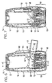
- Figure 1 is a section through a second embodiment of a device according to the invention.
- Figure 2 is a section on line X-X in Figure 1;
- FIGS 3 to 5 are perspective views showing three steps in the operation of the devices according to Figures 1, 2 and 6 to 9.
- Figure 6 is a section through a third embodiment of a device according to the invention.
- Figure 7 is a section on line Y-Y in Figure 6;
- Figure 8 is an exploded view of the embodiment shown in Figures 6 and 7;
- Figure 9 is an exploded perspective view, partly cut away, showing the dose indicator mechanism of the embodiment shown in figures 6 to 8.
- the inhalater device herein is suitable for dispensing medicament which is suitable for inhalation.
- medicaments are well known to those skilled in the art, for example for the treatment of asthma.
- Powdered medicaments suitable for this purpose include salbutamol, beclomethasone, salmeterol, fluticasone, formoterol, terbutaline, budesonide and flunisolide, and physiologically acceptable salts, solvates and esters or any combination thereof.
- Preferred medicaments are salbutamol, salbutamol sulphate, salmeterol, salmeterol xinafoate, fluticasone propionate, beclomethasone dipropionate and terbutaline sulphate.
- Individual isomers, such as R-salbutamol can also be used. It is to be understood that the medicament powder may consist purely of one or more active ingredients, or there may additionally be a carrier, for example lactose powder.
- the device shown in cross section in Figures 1 and 2 comprises a main body portion 5 which defines a reservoir 6 and a reservoir cover or end cap 2.
- the reservoir 6 contains a supply of medicament in the form of a powder (not shown).
- the reservoir cover 2 may be provided with a desiccant cartridge (not shown) to absorb moisture and reduce the risk of the powder in the reservoir absorbing moisture and undergoing agglomeration of the particles thereof.
- the cover 2 may be removably secured to the body 5 by any known means, for example by means of a screw thread or a snap fit, to enable refilling of the reservoir 6 with powder.
- a pharmaceutical grade rubber sealing ring 4 may be incorporated between the cover 2 and body 5 to prevent ingression of moisture into the reservoir 6.
- the device may be intended to be disposable after exhaustion of the supply of powder in the reservoir, in which case the cover 2 may be permanently secured to the body 5 by use of an adhesive, ultrasonic welding or any other method.
- main body portion 5 At its lower end the main body portion 5 is fitted with a base 10 which together with body 5 defines an aperture 11 which is offset from the vertical axis of the device and through which powder can pass from the reservoir to the dosing member 3. Powder is guided to the aperture by the walls of the reservoir which form a hopper. Extending laterally from the lower end of main body 5 is mouthpiece 7. If, however, the device were intended for nasal inhalation this would be replaced by a nosepiece.
- Dosing member 3 is mounted upon lower body portion 9 which is pivotally connected to main body 5 such that it may rotate about the vertical axis of the device. As explained in more detail below, lower body portion 9 serves to allow rotation of the dosing member 3 whilst maintaining the same in axial alignment with base 10. It also urges the dosing member 3 into close contact with base 10. Dust cover 33 is attached to lower body portion 9 through pivot 34.
- a weight 31 in the form of a ring encircles the reservoir 6 and is slidable longitudinally thereof.
- the locus of movement of the weight 31 is defined towards the top of the reservoir by an end stop 32 formed as an integral part of the body 5, and towards the bottom of the reservoir by base 10 which behaves as an anvil.
- the lower face of base 10 is provided with a highly polished smooth and flat surface as is the contacting upper face of dosing member 3. These surfaces are ground and polished to render a surface finish giving a flatness which does not undulate over its area by more than 0.003mm and a surface texture having a roughness average value (Ra) of 0.2 microns as internationally designated under ISO/R468, meaning that the average height of the irregularities constituting surface texture is 0.2 microns.
- Ra roughness average value
- These highly polished flat faces provide contacting surfaces between which there is substantially no clearance. It has been found that by providing such highly polished flat faces, the faces adhere to each other yet slide over each other as they are wrung together during assembly and use in the same way as mechanical slip gauges adhere to each other when wrung together.
- Air and powder are thus excluded from the interface between the base 10 and dosing member 3.
- the faces adhere firmly together but may be slid over eachother without affecting the closeness of the interfacial contact.
- Such contacting surfaces have been found to provide excellent sealing characteristics both in the static state and during the sliding motion of one face over the other preventing both loss of powder from and ingression of moisture into the reservoir 6 through the interface between the base 10 and dosing member 3.
- This type of kinetic or sliding seal obviates the need for any additional sealing means between base 10 and dosing member 3.
- the contacting surfaces of base 10 and dosing member 3 are made of a hard rigid material, and suitable materials include acetal resins, ceramics and metals.
- the two faces are formed by the surfaces of flat discs. It will be appreciated that disc shapes are not essential. Contact faces may be formed by the surfaces of a frusto-cone and a correspondingly frusto conical socket, by the contacting surfaces of two co-axial cylinders or by two correspondingly partially spherical contacting ball and socket surfaces.
- the user initially shakes the device in a generally upward and downward motion while maintaining the device in a generally upright orientation as shown in Figure 3.
- Weight 31 is thereby caused to travel up and down the reservoir, so repeatedly striking end stop 32 and base 10.
- the jolts which this produces causes the powder in the reservoir to be urged downwardly and to enter the metering recess 22.
- the aperture 11 is radially offset by an angle of 90° about the vertical axis of the device from the aperture 8 at the inner end of the mouthpiece to allow the dust cover and lower body portion 9 to be moved through 90° for ease of access to the mouthpiece.
- this angle can be substantially increased or slightly decreased according to the desired angle of rotation of the dust cover, lower body portion and dosing member.
- FIG. 6 A further embodiment of the invention is shown in Figures 6 to 9.
- the device shown in cross section in Figures 6 and 7 and in exploded view in figure 8 comprises an elongate main body portion 55 which defines a reservoir 56 and a reservoir cover or end cap 52.
- the reservoir 56 contains a supply of medicament in the form of a powder (not shown).
- the reservoir cover 52 is secured to the body 55 by a snap fit and a pharmaceutical grade rubber sealing ring 54 is incorporated between the cover 52 and body 55 to prevent ingression of moisture into the reservoir 56.
- the main body portion 55 is fitted with a base member 60 which together with body 55 defines an aperture 51 which is offset from the vertical axis of the device and through which powder can pass from the reservoir to a recess 65 in dosing member 53.
- the lower face of base member 60 is provided with a similarly highly polished smooth and flat surface to that described with reference to the embodiment shown in Figures 1 to 5 as is the upper face of dosing member 53. Powder is guided to the aperture by the walls of the reservoir which form a hopper. Extending laterally from the lower end of the main body 55 is mouthpiece 57.
- Dosing member 53 is mounted upon lower body assembly 59 which is pivotally connected to main body 55 such that it may rotate about the vertical axis of the device.
- Lower body assembly 59 serves to transmit rotational movement thereof to the dosing member 53 whilst maintaining the same in axial alignment with base member 60. It also urges dosing member 53 into close contact with base 60 by means of spring 61. Dust cover 63 (not shown in figures 6 and 7) is attached to lower body portion 69 through pivot 64.
- the wall of the main body 55 is provided with three longitudinal bores 58 substantially equidistantly spaced around the reservoir 56.
- a cylindrical weight 67 is slideably received in each of the bores 58.
- the weights 67 may be made of a rust resistant metal such as stainless steel or other hard material such as acetal resin.
- the bores are each blind at their upper ends and closed by a pressed-in stainless steel ball bearing 68 at their lower ends which also act as anvils against which weights 67 may impact as described later.
- a dose indicator drive means comprising a shaft 70 provided with a screw thread over much of its length, a sprung lug 71 at the base of the thread and a sprocket 72 with inclined teeth positioned below the lug is rotatably mounted within a bore 73 in the wall of the main body 55 (see figure 9).
- An indicator nut 77 is threaded onto the shaft with a projection protruding through an indicator window 74 in the wall of bore 73 which prevents the indicator nut 77 from rotating with shaft 70.
- Sprung lug 71 engages with teeth 75 formed within bore 73 to form a ratchet allowing shaft 70 to rotate in one direction only.
- Sprocket 72 is located adjacent the periphery of dosing member 53 which is provided with a second sprung lug 76.
- Operation of the device is similar to that described with reference to the embodiment shown in Figures 1 to 5.
- the user initially shakes the device in a generally upward and downward motion while maintaining the device in a generally upright orientation as shown in figure 3.
- Weights 67 are thereby caused to travel up and down bores 58 next to the reservoir, so repeatedly striking anvils 68.
- the vibrations which this produces are transmitted through base member 60 and body 55 to the powder in the reservoir, and this encourages powder to flow downwardly and enter metering recess 65 within dosing member 53.
- the pitch of the thread and the number of teeth on sprocket 72 are selected to ensure that the dose indicator nut travels from the uppermost "full” position to the lowermost "empty” position when the device has been used sufficiently to deliver its prescribed number of doses, so indicting to the user that the device is empty.
Abstract
Description
- This invention relates to an inhalation device by means of which metered doses of medicament in the form of a powder can be dispersed to a user. In particular it relates to a device of the type in which the medicament powder is held in bulk in a reservoir with which the device is provided, and is metered to the user from the reservoir.
- In devices of the type just described, it is difficult to obtain doses which are equal to a nominal value to within the appropriate tolerance. It will be understood that the tolerance permitted is often very small, as it is important that the user should be given a dose which is very close to the nominal value. In order to maintain the medicament powder in a manageable state it needs to be kept dry. Any ingress of moisture into the reservoir from outside can cause the medicament powder to agglomerate and this may be detrimental to its free flowing properties rendering it difficult to meter consistent doses from the reservoir. In the absence of adequate reservoir sealing it may be necessary to incorporate a desiccant cartridge into the reservoir to absorb any moisture that does enter. This is often insufficient to prevent deterioration of the medicament powder.
- WO 92/00771 discloses a dry powder inhaler, according to the preamble of claim 1, with means for ensuring that the cup from which the substance is dispensed is substantially free from the substance before being presented to the storage chamber. FR A 967 494 discloses a dry powder inhalation device having a ball to jolt the powder to ensure it is fine enough to be dislodged into the airflow, ready for inhalation. FR 2233842 discloses a new type of dispenser which can be instantly unblocked.
- It is an object of the present invention to provide a device of the type just described, in which doses can be repeatedly accurately dispersed, without requiring a dispensing mechanism of undue complexity.
- It is a further object of the present invention to provide a device of the type just described, but which additionally incorporates a simple and efficient sealing means to prevent ingress of moisture into the reservoir.
- According to the present invention there is provided an inhalation device comprising a body defining a reservoir for medicament in the form of a powder, an outlet through which a user can inhale, and a dosing member with at least one metering recess formed therein, the dosing member being moveable between a first position in which the at least one metering recess communicates with the reservoir to receive a dose of powder therefrom and a second position in which the at least one metering recess communicates with the outlet to permit the user to inhale the dose, the at least one metering recess being formed in a face of the dosing member, the said face being mounted in contact against a similar mating face of the body.
- The face of the dosing member and the mating face of the body are sealing faces with highly polished smooth surfaces which form a kinetic seal which excludes substantially all air from the interface therebetween.
- The sealing faces have a surface texture sufficiently smooth to have a roughness average value (Ra) of 0.5 microns or less, preferably 0.2 microns or less.
- Suitably the sealing faces are flat. More suitably they have a flatness of 0.005mm or less, preferably 0.003mm or less.
- Alternatively the sealing faces may be frusto-conical. The sealing faces may alternatively be cylindrical. In a further alternative the sealing faces may be spherical.
- The sealing surfaces are suitably made of a hard rigid material such as acetal resins, ceramics or metals.
- Suitably, the inhalation device includes a reservoir for medicament in the form of a powder, an outlet through which a user can inhale, a metering means adapted to communicate with the reservoir to receive a dose of powder therefrom and with the outlet to permit the user to inhale the dose, and at least one weight moveable in the device and adapted, when the device is shaken, to strike an anvil surface defined in the device.
- Suitably, the inhalation device includes a body forming a reservoir for medicaments in the form of a powder, an outlet through which a user can inhale, and a dosing member with at least one metering recess formed therein, the dosing member being moveable between a position in which the at least one metering recess communicates with the reservoir to receive a dose of powder therefrom and a position in which the at least one metering recess communicates with the outlet to permit the user to inhale the dose, the at least one metering recess being formed in a face of the dosing member, the said face being mounted in contact against a similar mating face of the body. The said face of the dosing member and the said mating face of the body have highly polished smooth surfaces which form a contacting face to face kinetic seal which excludes substantially all air from the interface. The term 'kinetic seal' in this context means a seal that can withstand relative movement of the two faces.
- Suitably, the sealing faces form a sliding seal which excludes substantially all air from the interface therebetween.
- The invention is further described below with reference to the accompanying drawings in which:
- Figure 1 is a section through a second embodiment of a device according to the invention;
- Figure 2 is a section on line X-X in Figure 1; and
- Figures 3 to 5 are perspective views showing three steps in the operation of the devices according to Figures 1, 2 and 6 to 9.
- Figure 6 is a section through a third embodiment of a device according to the invention.
- Figure 7 is a section on line Y-Y in Figure 6;
- Figure 8 is an exploded view of the embodiment shown in Figures 6 and 7; and
- Figure 9 is an exploded perspective view, partly cut away, showing the dose indicator mechanism of the embodiment shown in figures 6 to 8.
- The inhalater device herein is suitable for dispensing medicament which is suitable for inhalation. Many such medicaments are well known to those skilled in the art, for example for the treatment of asthma. Powdered medicaments suitable for this purpose include salbutamol, beclomethasone, salmeterol, fluticasone, formoterol, terbutaline, budesonide and flunisolide, and physiologically acceptable salts, solvates and esters or any combination thereof. Preferred medicaments are salbutamol, salbutamol sulphate, salmeterol, salmeterol xinafoate, fluticasone propionate, beclomethasone dipropionate and terbutaline sulphate. Individual isomers, such as R-salbutamol, can also be used. It is to be understood that the medicament powder may consist purely of one or more active ingredients, or there may additionally be a carrier, for example lactose powder.
- The device shown in cross section in Figures 1 and 2 comprises a
main body portion 5 which defines areservoir 6 and a reservoir cover orend cap 2. Thereservoir 6 contains a supply of medicament in the form of a powder (not shown). - The
reservoir cover 2 may be provided with a desiccant cartridge (not shown) to absorb moisture and reduce the risk of the powder in the reservoir absorbing moisture and undergoing agglomeration of the particles thereof. Thecover 2 may be removably secured to thebody 5 by any known means, for example by means of a screw thread or a snap fit, to enable refilling of thereservoir 6 with powder. In this case a pharmaceutical grade rubber sealing ring 4 may be incorporated between thecover 2 andbody 5 to prevent ingression of moisture into thereservoir 6. Alternatively, the device may be intended to be disposable after exhaustion of the supply of powder in the reservoir, in which case thecover 2 may be permanently secured to thebody 5 by use of an adhesive, ultrasonic welding or any other method. - At its lower end the
main body portion 5 is fitted with abase 10 which together withbody 5 defines anaperture 11 which is offset from the vertical axis of the device and through which powder can pass from the reservoir to thedosing member 3. Powder is guided to the aperture by the walls of the reservoir which form a hopper. Extending laterally from the lower end ofmain body 5 is mouthpiece 7. If, however, the device were intended for nasal inhalation this would be replaced by a nosepiece.Dosing member 3 is mounted upon lower body portion 9 which is pivotally connected tomain body 5 such that it may rotate about the vertical axis of the device. As explained in more detail below, lower body portion 9 serves to allow rotation of thedosing member 3 whilst maintaining the same in axial alignment withbase 10. It also urges thedosing member 3 into close contact withbase 10.Dust cover 33 is attached to lower body portion 9 throughpivot 34. - A
weight 31 in the form of a ring encircles thereservoir 6 and is slidable longitudinally thereof. The locus of movement of theweight 31 is defined towards the top of the reservoir by anend stop 32 formed as an integral part of thebody 5, and towards the bottom of the reservoir bybase 10 which behaves as an anvil. It is to be understood that whilst the device described herein incorporates a weight for the purpose described below, the weight is not an essential element of the invention and it might be chosen to omit the incorporation of the weight. - The lower face of
base 10 is provided with a highly polished smooth and flat surface as is the contacting upper face ofdosing member 3. These surfaces are ground and polished to render a surface finish giving a flatness which does not undulate over its area by more than 0.003mm and a surface texture having a roughness average value (Ra) of 0.2 microns as internationally designated under ISO/R468, meaning that the average height of the irregularities constituting surface texture is 0.2 microns. These highly polished flat faces provide contacting surfaces between which there is substantially no clearance. It has been found that by providing such highly polished flat faces, the faces adhere to each other yet slide over each other as they are wrung together during assembly and use in the same way as mechanical slip gauges adhere to each other when wrung together. Air and powder are thus excluded from the interface between thebase 10 and dosingmember 3. When assembled the faces adhere firmly together but may be slid over eachother without affecting the closeness of the interfacial contact. Such contacting surfaces have been found to provide excellent sealing characteristics both in the static state and during the sliding motion of one face over the other preventing both loss of powder from and ingression of moisture into thereservoir 6 through the interface between thebase 10 and dosingmember 3. This type of kinetic or sliding seal obviates the need for any additional sealing means betweenbase 10 anddosing member 3. The contacting surfaces ofbase 10 anddosing member 3 are made of a hard rigid material, and suitable materials include acetal resins, ceramics and metals. - In the embodiment described, the two faces are formed by the surfaces of flat discs. It will be appreciated that disc shapes are not essential. Contact faces may be formed by the surfaces of a frusto-cone and a correspondingly frusto conical socket, by the contacting surfaces of two co-axial cylinders or by two correspondingly partially spherical contacting ball and socket surfaces.
- In operation, the user initially shakes the device in a generally upward and downward motion while maintaining the device in a generally upright orientation as shown in Figure 3.
Weight 31 is thereby caused to travel up and down the reservoir, so repeatedlystriking end stop 32 andbase 10. The jolts which this produces causes the powder in the reservoir to be urged downwardly and to enter themetering recess 22. - The user then opens
dust cover 33, as shown in Figure 4, and rotates the cover which is connected to lower body portion 9 through 90° to move thedust cover 33 away from the mouthpiece 7 to allow access thereto and to bring therecess 22 into alignment with the aperture 8 leading to the mouthpiece 7. The user knows when this position has been reached as the lower body portion 9 engages a stop (not shown) and will not move any further. The user then inhales through mouthpiece 7. After inhalation the user returns the lower body portion 9 to its initial position and closes thedust cover 33. - In the device shown in Figures 1 and 2 the
aperture 11 is radially offset by an angle of 90° about the vertical axis of the device from the aperture 8 at the inner end of the mouthpiece to allow the dust cover and lower body portion 9 to be moved through 90° for ease of access to the mouthpiece. However, it will be appreciated that this angle can be substantially increased or slightly decreased according to the desired angle of rotation of the dust cover, lower body portion and dosing member. - Further possible modifications to the device described include incorporation of a suitable dose counting mechanism to give the user an indication of the amount of powder remaining in the device.
- A further embodiment of the invention is shown in Figures 6 to 9. As in the previous embodiment, the device shown in cross section in Figures 6 and 7 and in exploded view in figure 8 comprises an elongate
main body portion 55 which defines areservoir 56 and a reservoir cover orend cap 52. Thereservoir 56 contains a supply of medicament in the form of a powder (not shown). Thereservoir cover 52 is secured to thebody 55 by a snap fit and a pharmaceutical graderubber sealing ring 54 is incorporated between thecover 52 andbody 55 to prevent ingression of moisture into thereservoir 56. - At its lower end the
main body portion 55 is fitted with abase member 60 which together withbody 55 defines anaperture 51 which is offset from the vertical axis of the device and through which powder can pass from the reservoir to arecess 65 indosing member 53. The lower face ofbase member 60 is provided with a similarly highly polished smooth and flat surface to that described with reference to the embodiment shown in Figures 1 to 5 as is the upper face ofdosing member 53. Powder is guided to the aperture by the walls of the reservoir which form a hopper. Extending laterally from the lower end of themain body 55 ismouthpiece 57.Dosing member 53 is mounted uponlower body assembly 59 which is pivotally connected tomain body 55 such that it may rotate about the vertical axis of the device.Lower body assembly 59 serves to transmit rotational movement thereof to thedosing member 53 whilst maintaining the same in axial alignment withbase member 60. It also urgesdosing member 53 into close contact withbase 60 by means ofspring 61. Dust cover 63 (not shown in figures 6 and 7) is attached tolower body portion 69 throughpivot 64. - The wall of the
main body 55 is provided with threelongitudinal bores 58 substantially equidistantly spaced around thereservoir 56. Acylindrical weight 67 is slideably received in each of thebores 58. Theweights 67 may be made of a rust resistant metal such as stainless steel or other hard material such as acetal resin. The bores are each blind at their upper ends and closed by a pressed-in stainlesssteel ball bearing 68 at their lower ends which also act as anvils against whichweights 67 may impact as described later. - A dose indicator drive means comprising a
shaft 70 provided with a screw thread over much of its length, a sprunglug 71 at the base of the thread and asprocket 72 with inclined teeth positioned below the lug is rotatably mounted within abore 73 in the wall of the main body 55 (see figure 9). Anindicator nut 77 is threaded onto the shaft with a projection protruding through anindicator window 74 in the wall ofbore 73 which prevents theindicator nut 77 from rotating withshaft 70.Sprung lug 71 engages withteeth 75 formed withinbore 73 to form aratchet allowing shaft 70 to rotate in one direction only.Sprocket 72 is located adjacent the periphery ofdosing member 53 which is provided with a second sprunglug 76. - Operation of the device is similar to that described with reference to the embodiment shown in Figures 1 to 5. The user initially shakes the device in a generally upward and downward motion while maintaining the device in a generally upright orientation as shown in figure 3.
Weights 67 are thereby caused to travel up and down bores 58 next to the reservoir, so repeatedly strikinganvils 68. The vibrations which this produces are transmitted throughbase member 60 andbody 55 to the powder in the reservoir, and this encourages powder to flow downwardly and entermetering recess 65 withindosing member 53. - The user then opens
dust cover 63, as shown in Figure 4, and rotates the cover which is connected to lowerbody assembly 59 through 90° to movedust cover 63 away frommouthpiece 57 to allow access thereto and to bringrecess 65 into alignment with the aperture at 66 leading to themouthpiece 57. As thedosing member 53 rotates with thelower body assembly 59,lug 76 engages an inclined tooth presented bysprocket 72 of the dose indicator drive means. The dose indicator drive means is prevented from turning in the direction urged bylug 76 by virtue of the ratchet mechanism formed byteeth 75 andlug 71. As a result, lug 76 rides over the inclined tooth and out of engagement withsprocket 72. Thelower body assembly 59 engages a stop (not shown) and will not move any further when therecess 65 is correctly aligned withaperture 66. - The user now inhales through
mouthpiece 57. Air is drawn throughgrill 80 andpassage 81, defined bybody 55 andhole 82 inbase member 60, and entrains the powder inrecess 65 ofdosing member 53. The airflow draws the entrained powder through themouthpiece 57 and is inhaled by the user. Further air is drawn into the mouthpiece throughholes 82 on either side ofmouthpiece 57 and this creates turbulence which helps to break-up any agglomerates of powder entrained. - After inhalation the user returns
lower body assembly 59 to its initial position and closes thedust cover 63. Asdosing member 53 rotates, lug 76 again engagessprocket 72 of the dose indicator drive means. As the ratchet mechanism formed byteeth 75 andlug 71 allows movement of the dose indicator drive means in the direction as now urged bylug 76, the dose indicator drive means is rotated by one tooth pitch through engagement withlug 76 as it passessprocket 72. Rotation of the dose indicator drive means causes the captivedose indicator nut 73 to travel down threadedshaft 70. The pitch of the thread and the number of teeth onsprocket 72 are selected to ensure that the dose indicator nut travels from the uppermost "full" position to the lowermost "empty" position when the device has been used sufficiently to deliver its prescribed number of doses, so indicting to the user that the device is empty.
Claims (14)
- An inhalation device comprising a body (1) forming a reservoir (6) for medicaments in the form of a powder, an outlet (7) through which a user can inhale, and a dosing member (3) with at least one metering recess (22) formed therein, the dosing member (3) being moveable between a position in which the at least one metering recess (22) communicates with the reservoir (6) to receive a dose of powder therefrom and a position in which the at least one metering recess (22) communicates with the outlet (7) to permit the user to inhale the dose, the at least one metering recess (22) being formed in a face of the dosing member (3), the said face being mounted in contact against a similar mating face of the body (1), characterised in that the said face of the dosing member (3) and the said mating face of the body (1) have highly polished smooth surfaces with a roughness average value (Ra) of 0.5 µm or less which form a contacting face to face kinetic seal which excludes substantially all air from the interface.
- An inhalation device according to claim 1, wherein the kinetic seal is a shiding seal.
- A device according to either of claims 1 or 2, characterised in that the sealing faces adhere to each other.
- A device according to claim 3, characterised in that the sealing faces have a roughness average value (Ra) of 0.2 microns or less.
- A device according to either of claims 3 or 4, characterised in that the sealing faces are flat.
- A device according to claim 5, characterised in that the sealing faces have a flatness of 0.005 mm or less.
- A device according to claim 6, characterised in that the sealing faces have a flatness of 0.003 mm or less.
- A device according to either of claims 3 or 4, characterised in that the sealing faces are cylindrical.
- A device according to either of claims 3 or 4, characterised in that the sealing faces are spherical.
- A device according to any of claims 1 to 9, characterised in that the sealing faces are made of a hard rigid material.
- A device according to claim 10, characterised in that the sealing faces are made of acetal resin.
- A device according to claim 10, characterised in that the sealing faces are made of ceramics.
- A device according to claim 10, characterised in that the sealing faces are made of metal.
- A device according to any preceding claim, further comprising a dose indicating means adapted to display to a user the quantity of medicament remaining within the reservoir (6).
Applications Claiming Priority (5)
| Application Number | Priority Date | Filing Date | Title |
|---|---|---|---|
| GB9418702A GB9418702D0 (en) | 1994-09-16 | 1994-09-16 | Device |
| GB9418702 | 1994-09-16 | ||
| GBGB9507713.7A GB9507713D0 (en) | 1995-04-13 | 1995-04-13 | Device |
| GB9507713 | 1995-04-13 | ||
| EP95932737A EP0835146B1 (en) | 1994-09-16 | 1995-09-13 | Inhalation device |
Related Parent Applications (1)
| Application Number | Title | Priority Date | Filing Date |
|---|---|---|---|
| EP95932737A Division EP0835146B1 (en) | 1994-09-16 | 1995-09-13 | Inhalation device |
Publications (2)
| Publication Number | Publication Date |
|---|---|
| EP0979661A1 EP0979661A1 (en) | 2000-02-16 |
| EP0979661B1 true EP0979661B1 (en) | 2002-12-04 |
Family
ID=26305638
Family Applications (2)
| Application Number | Title | Priority Date | Filing Date |
|---|---|---|---|
| EP99119531A Expired - Lifetime EP0979661B1 (en) | 1994-09-16 | 1995-09-13 | Inhalation device |
| EP95932737A Expired - Lifetime EP0835146B1 (en) | 1994-09-16 | 1995-09-13 | Inhalation device |
Family Applications After (1)
| Application Number | Title | Priority Date | Filing Date |
|---|---|---|---|
| EP95932737A Expired - Lifetime EP0835146B1 (en) | 1994-09-16 | 1995-09-13 | Inhalation device |
Country Status (19)
| Country | Link |
|---|---|
| US (3) | US6065471A (en) |
| EP (2) | EP0979661B1 (en) |
| JP (1) | JPH10505764A (en) |
| KR (1) | KR970706032A (en) |
| AT (1) | ATE228024T1 (en) |
| AU (1) | AU710027B2 (en) |
| BR (1) | BR9508935A (en) |
| CA (1) | CA2199858A1 (en) |
| DE (2) | DE69529104T2 (en) |
| FI (1) | FI971101A0 (en) |
| HU (1) | HU219117B (en) |
| IL (1) | IL115298A (en) |
| IS (1) | IS4437A (en) |
| MX (1) | MX9701957A (en) |
| NO (1) | NO971207L (en) |
| NZ (1) | NZ293269A (en) |
| RU (1) | RU2157251C2 (en) |
| TW (1) | TW301611B (en) |
| WO (1) | WO1996008284A2 (en) |
Cited By (1)
| Publication number | Priority date | Publication date | Assignee | Title |
|---|---|---|---|---|
| US9179691B2 (en) | 2007-12-14 | 2015-11-10 | Aerodesigns, Inc. | Delivering aerosolizable food products |
Families Citing this family (77)
| Publication number | Priority date | Publication date | Assignee | Title |
|---|---|---|---|---|
| SE9302550D0 (en) * | 1993-07-30 | 1993-07-30 | Ernst Hoerlin | POWDER INHALES |
| US6065471A (en) * | 1994-09-16 | 2000-05-23 | Laboratoire Glaxo Wellcome | Inhalation device |
| US5826633A (en) | 1996-04-26 | 1998-10-27 | Inhale Therapeutic Systems | Powder filling systems, apparatus and methods |
| FR2753791B1 (en) * | 1996-09-20 | 1998-11-20 | POWDER DISPENSER WITH TILTING DOSING CHAMBER | |
| AU735126B2 (en) * | 1997-01-08 | 2001-06-28 | Glaxo Group Limited | Inhalation device |
| GB9700226D0 (en) * | 1997-01-08 | 1997-02-26 | Glaxo Group Ltd | Inhalation device |
| GB2323041B (en) * | 1997-03-14 | 2001-01-10 | Bespak Plc | Inhalation apparatus |
| US6182712B1 (en) | 1997-07-21 | 2001-02-06 | Inhale Therapeutic Systems | Power filling apparatus and methods for their use |
| SE9704185D0 (en) | 1997-11-14 | 1997-11-14 | Astra Pharma Prod | Inhalation device |
| US7743765B2 (en) * | 1997-11-14 | 2010-06-29 | Astrazeneca Ab | Inhalation device |
| DE19831525A1 (en) * | 1998-07-14 | 2000-01-20 | Pfeiffer Erich Gmbh & Co Kg | Media Donor |
| ES2272252T3 (en) * | 1999-01-14 | 2007-05-01 | Teijin Limited | DEVICE FOR MANAGING A CONSTANT AMOUNT OF A POWDER BODY. |
| PL352615A1 (en) * | 1999-06-05 | 2003-08-25 | Innovata Biomed Ltd | Delivery system |
| GB9920839D0 (en) | 1999-09-04 | 1999-11-10 | Innovata Biomed Ltd | Inhaler |
| GB9924780D0 (en) | 1999-10-21 | 1999-12-22 | Glaxo Group Ltd | Medicament dispenser |
| GB9924808D0 (en) | 1999-10-21 | 1999-12-22 | Glaxo Group Ltd | Medicament dispenser |
| DE60020597D1 (en) * | 1999-12-07 | 2005-07-07 | Orion Corp | MEHRFACHPULVERINHALATOR |
| US7304750B2 (en) | 1999-12-17 | 2007-12-04 | Nektar Therapeutics | Systems and methods for non-destructive mass sensing |
| DE19961300A1 (en) * | 1999-12-18 | 2001-06-21 | Asta Medica Ag | Storage system for medicinal products in powder form and inhaler equipped with them |
| CN100341483C (en) * | 2000-02-28 | 2007-10-10 | 维克丘拉有限公司 | Improvements in or relating to delivery of oral drugs |
| WO2001078735A1 (en) * | 2000-04-13 | 2001-10-25 | Innovata Biomed Limited | Medicaments for treating respiratory disorders comprising formoterol and fluticasone |
| US6644305B2 (en) * | 2000-04-14 | 2003-11-11 | Trudell Medical International | Nasal inhaler |
| GB0015043D0 (en) | 2000-06-21 | 2000-08-09 | Glaxo Group Ltd | Medicament dispenser |
| GB0015034D0 (en) | 2000-06-21 | 2000-08-09 | Glaxo Group Ltd | Inhalation device |
| PE20020074A1 (en) * | 2000-06-23 | 2002-02-05 | Norton Healthcare Ltd | DOSING SYSTEM FOR MEDICATION INHALER |
| FR2811576B1 (en) * | 2000-07-13 | 2003-01-24 | Henri Bocquee | APPARATUS OR APPARATUS FOR ADMINISTERING POWDERY ACTIVE PRODUCTS OF THE DRUG OR VACCINE TYPE, BY PULMONARY ROUTE |
| SE517229C2 (en) * | 2000-09-25 | 2002-05-14 | Microdrug Ag | Continuous dry powder inhaler |
| US6644309B2 (en) | 2001-01-12 | 2003-11-11 | Becton, Dickinson And Company | Medicament respiratory delivery device and method |
| US6443152B1 (en) | 2001-01-12 | 2002-09-03 | Becton Dickinson And Company | Medicament respiratory delivery device |
| US6722364B2 (en) * | 2001-01-12 | 2004-04-20 | Becton, Dickinson And Company | Medicament inhalation delivery devices and methods for using the same |
| WO2002062317A2 (en) * | 2001-02-06 | 2002-08-15 | Innovata Biomed Limited | Bimodal dry powder formulation for inhalation |
| FI20010538A0 (en) * | 2001-03-16 | 2001-03-16 | Orion Corp | The powder inhaler |
| GB0122725D0 (en) * | 2001-09-21 | 2001-11-14 | Glaxo Group Ltd | Drug dispensing components |
| GB0128148D0 (en) | 2001-11-23 | 2002-01-16 | Innovata Biomed Ltd | Assembly |
| US7258118B2 (en) * | 2002-01-24 | 2007-08-21 | Sofotec Gmbh & Co, Kg | Pharmaceutical powder cartridge, and inhaler equipped with same |
| US6830046B2 (en) | 2002-04-29 | 2004-12-14 | Hewlett-Packard Development Company, L.P. | Metered dose inhaler |
| US7396341B2 (en) * | 2002-08-28 | 2008-07-08 | Boehringer Ingelheim International Gmbh | Blocking device for a locking stressing mechanism having a spring-actuated output drive device |
| EP1452198A4 (en) | 2002-10-11 | 2006-11-02 | Otsuka Pharma Co Ltd | Powder inhalation device |
| AU2008201239B2 (en) * | 2002-10-11 | 2010-02-18 | Otsuka Pharmaceutical Co., Ltd. | Powder inhalation |
| US20030051727A1 (en) * | 2002-11-04 | 2003-03-20 | Haan Richard J | Aerosol mdi overcap containing desiccant |
| DE10300032B3 (en) * | 2003-01-03 | 2004-05-27 | E. Braun Gmbh | Inhaler for powdered medicament has pivoted inhalation tube which shuts off powder supply when in out-of-use position, and doses powder into airflow when in use |
| FR2858867B1 (en) * | 2003-08-12 | 2005-11-04 | Valois Sa | DOSING INDICATOR FOR FLUID PRODUCT DISPENSING DEVICE |
| AU2004291542A1 (en) * | 2003-11-18 | 2005-06-02 | Yansong Shan | Healthy pleasurable inhalation device |
| US7467630B2 (en) * | 2004-02-11 | 2008-12-23 | Hewlett-Packard Development Company, L.P. | Medicament dispenser |
| US7481213B2 (en) * | 2004-02-11 | 2009-01-27 | Hewlett-Packard Development Company, L.P. | Medicament dispenser |
| BRPI0509348A (en) | 2004-04-21 | 2007-09-11 | Innovata Biomed Ltd | inhaler |
| GB0409197D0 (en) | 2004-04-24 | 2004-05-26 | Innovata Biomed Ltd | Device |
| JP4500280B2 (en) * | 2005-06-08 | 2010-07-14 | 日立オートモティブシステムズ株式会社 | Powder drug dispenser |
| FR2895374B1 (en) * | 2005-12-27 | 2010-08-27 | Valois Sas | RING FOR AEROSOL VALVE. |
| US8202535B2 (en) | 2006-01-06 | 2012-06-19 | Acelrx Pharmaceuticals, Inc. | Small-volume oral transmucosal dosage forms |
| US8252329B2 (en) | 2007-01-05 | 2012-08-28 | Acelrx Pharmaceuticals, Inc. | Bioadhesive drug formulations for oral transmucosal delivery |
| US9066847B2 (en) * | 2007-01-05 | 2015-06-30 | Aceirx Pharmaceuticals, Inc. | Storage and dispensing devices for administration of oral transmucosal dosage forms |
| US8753308B2 (en) | 2006-01-06 | 2014-06-17 | Acelrx Pharmaceuticals, Inc. | Methods for administering small volume oral transmucosal dosage forms using a dispensing device |
| US8252328B2 (en) * | 2006-01-06 | 2012-08-28 | Acelrx Pharmaceuticals, Inc. | Bioadhesive drug formulations for oral transmucosal delivery |
| US8865743B2 (en) | 2006-01-06 | 2014-10-21 | Acelrx Pharmaceuticals, Inc. | Small volume oral transmucosal dosage forms containing sufentanil for treatment of pain |
| US9289583B2 (en) | 2006-01-06 | 2016-03-22 | Acelrx Pharmaceuticals, Inc. | Methods for administering small volume oral transmucosal dosage forms using a dispensing device |
| US8535714B2 (en) | 2006-01-06 | 2013-09-17 | Acelrx Pharmaceuticals, Inc. | Small volume oral transmucosal dosage forms containing sufentanil for treatment of pain |
| CN101495080B (en) * | 2006-01-06 | 2013-10-23 | 阿塞尔Rx制药有限公司 | Drug storage and dispensing devices and systems comprising same |
| US8357114B2 (en) | 2006-01-06 | 2013-01-22 | Acelrx Pharmaceuticals, Inc. | Drug dispensing device with flexible push rod |
| EP2058025B1 (en) | 2007-11-09 | 2014-09-03 | Hitachi Ltd. | Powder medicine administering apparatus |
| GB0800457D0 (en) * | 2008-01-11 | 2008-02-20 | Innovata Biomed Ltd | Improvements in or relating to inhalers |
| GB0800459D0 (en) * | 2008-01-11 | 2008-02-20 | Innovata Biomed Ltd | Improvements in or relating to inhalers |
| US8945592B2 (en) | 2008-11-21 | 2015-02-03 | Acelrx Pharmaceuticals, Inc. | Sufentanil solid dosage forms comprising oxygen scavengers and methods of using the same |
| WO2010107761A1 (en) | 2009-03-18 | 2010-09-23 | Acelrx Pharmaceuticals, Inc. | Improved storage and dispensing devices for administration of oral transmucosal dosage forms |
| CN102458543B (en) | 2009-05-18 | 2015-02-04 | 3M创新有限公司 | Dry powder inhalers |
| EP2498848A2 (en) | 2009-11-12 | 2012-09-19 | Stc.Unm | Dry powder inhaler with flutter dispersion member |
| GB201006759D0 (en) * | 2010-04-23 | 2010-06-09 | 3M Innovative Properties Co | An inhaler |
| JP6050758B2 (en) | 2010-12-07 | 2016-12-21 | レスピラ セラピューティクス インコーポレイテッドRespira Therapeutics,Inc. | Dry powder inhaler and method of operating the same |
| JP5603273B2 (en) * | 2011-03-18 | 2014-10-08 | 日立オートモティブシステムズ株式会社 | Powder drug dispenser |
| US10463815B2 (en) | 2012-02-21 | 2019-11-05 | Respira Therapeutics, Inc. | Inhaler to deliver substances for prophylaxis or prevention of disease or injury caused by the inhalation of biological or chemical agents |
| US10525216B2 (en) | 2012-02-21 | 2020-01-07 | Respira Therapeutics, Inc. | Powder dispersion methods and devices |
| WO2015034709A1 (en) * | 2013-09-04 | 2015-03-12 | 3M Innovative Properties Company | Dry-powder inhaler and method |
| TWI566795B (en) * | 2014-07-24 | 2017-01-21 | 心誠鎂行動醫電股份有限公司 | Portable ultrasonic nebulizer and protection structure thereof |
| MY187877A (en) | 2014-12-23 | 2021-10-26 | Acelrx Pharmaceuticals Inc | Systems, devices and methods for dispensing oral transmucosal dosage forms |
| EP3294390B1 (en) * | 2015-05-08 | 2022-10-05 | Iconovo AB | Dry powder inhaler |
| GB201615186D0 (en) * | 2016-09-07 | 2016-10-19 | 3M Innovative Properties Co | Energy storage mechanism for an inhaler |
| WO2023117929A1 (en) * | 2021-12-21 | 2023-06-29 | Chiesi Farmaceutici S.P.A. | Powder inhaler |
Family Cites Families (19)
| Publication number | Priority date | Publication date | Assignee | Title |
|---|---|---|---|---|
| BE483136A (en) * | 1947-09-04 | 1942-06-30 | ||
| US2470296A (en) * | 1948-04-30 | 1949-05-17 | Abbott Lab | Inhalator |
| US2534636A (en) * | 1949-02-12 | 1950-12-19 | American Cyanamid Co | Powder dispenser |
| US2587215A (en) * | 1949-04-27 | 1952-02-26 | Frank P Priestly | Inhalator |
| FR2233842A5 (en) * | 1973-06-13 | 1975-01-10 | Bour Armand Le | Powder shaker with unblocking device - weight sliding in internal tube provides unblocking shocks |
| US4274403A (en) * | 1979-08-29 | 1981-06-23 | Struve Roger L | Inhaler |
| GB9015522D0 (en) * | 1990-07-13 | 1990-08-29 | Braithwaite Philip W | Inhaler |
| EP0493560A1 (en) * | 1990-07-27 | 1992-07-08 | Franco Del Bon | Inhalation device |
| AU650953B2 (en) * | 1991-03-21 | 1994-07-07 | Novartis Ag | Inhaler |
| US5295479A (en) * | 1991-04-15 | 1994-03-22 | Leiras Oy | Device intended for measuring a dose of powdered medicament for inhalation |
| CN1050764C (en) * | 1991-06-26 | 2000-03-29 | 先灵公司 | Inhalation device for powdered medicaments |
| US5394868A (en) * | 1992-06-25 | 1995-03-07 | Schering Corporation | Inhalation device for powdered medicaments |
| WO1994014492A2 (en) | 1992-12-18 | 1994-07-07 | Schering Corporation | Inhaler for powdered medications |
| US5372128A (en) * | 1993-04-14 | 1994-12-13 | Habley Medical Technology Corporation | Fluidizing powder inhaler |
| US5349947A (en) * | 1993-07-15 | 1994-09-27 | Newhouse Michael T | Dry powder inhaler and process that explosively discharges a dose of powder and gas from a soft plastic pillow |
| GB9326574D0 (en) * | 1993-12-31 | 1994-03-02 | King S College London | Dry power inhalers |
| US6065471A (en) * | 1994-09-16 | 2000-05-23 | Laboratoire Glaxo Wellcome | Inhalation device |
| ATE216903T1 (en) * | 1996-02-21 | 2002-05-15 | Schering Corp | INHALER FOR POWDER-TYPE MEDICATION |
| GB9700226D0 (en) * | 1997-01-08 | 1997-02-26 | Glaxo Group Ltd | Inhalation device |
-
1995
- 1995-09-13 US US08/793,612 patent/US6065471A/en not_active Expired - Lifetime
- 1995-09-13 NZ NZ293269A patent/NZ293269A/en unknown
- 1995-09-13 EP EP99119531A patent/EP0979661B1/en not_active Expired - Lifetime
- 1995-09-13 JP JP8509912A patent/JPH10505764A/en active Pending
- 1995-09-13 RU RU97106014/14A patent/RU2157251C2/en active
- 1995-09-13 BR BR9508935A patent/BR9508935A/en not_active Application Discontinuation
- 1995-09-13 AU AU35670/95A patent/AU710027B2/en not_active Ceased
- 1995-09-13 HU HU9800106A patent/HU219117B/en not_active IP Right Cessation
- 1995-09-13 CA CA002199858A patent/CA2199858A1/en not_active Abandoned
- 1995-09-13 DE DE69529104T patent/DE69529104T2/en not_active Expired - Lifetime
- 1995-09-13 EP EP95932737A patent/EP0835146B1/en not_active Expired - Lifetime
- 1995-09-13 MX MX9701957A patent/MX9701957A/en not_active IP Right Cessation
- 1995-09-13 DE DE69528912T patent/DE69528912T2/en not_active Expired - Lifetime
- 1995-09-13 WO PCT/EP1995/003603 patent/WO1996008284A2/en not_active Application Discontinuation
- 1995-09-13 KR KR1019970701710A patent/KR970706032A/en not_active Application Discontinuation
- 1995-09-13 AT AT95932737T patent/ATE228024T1/en not_active IP Right Cessation
- 1995-09-14 IL IL11529895A patent/IL115298A/en not_active IP Right Cessation
- 1995-11-04 TW TW084111704A patent/TW301611B/zh active
-
1997
- 1997-03-07 IS IS4437A patent/IS4437A/en unknown
- 1997-03-14 NO NO971207A patent/NO971207L/en not_active Application Discontinuation
- 1997-03-14 FI FI971101A patent/FI971101A0/en unknown
-
2000
- 2000-02-01 US US09/494,942 patent/US6220243B1/en not_active Expired - Fee Related
- 2000-10-25 US US09/694,892 patent/US6484718B1/en not_active Expired - Fee Related
Cited By (1)
| Publication number | Priority date | Publication date | Assignee | Title |
|---|---|---|---|---|
| US9179691B2 (en) | 2007-12-14 | 2015-11-10 | Aerodesigns, Inc. | Delivering aerosolizable food products |
Also Published As
| Publication number | Publication date |
|---|---|
| US6220243B1 (en) | 2001-04-24 |
| DE69529104D1 (en) | 2003-01-16 |
| AU3567095A (en) | 1996-03-29 |
| EP0835146B1 (en) | 2002-11-20 |
| DE69529104T2 (en) | 2003-07-17 |
| IL115298A (en) | 2000-07-26 |
| FI971101A (en) | 1997-03-14 |
| WO1996008284A2 (en) | 1996-03-21 |
| IS4437A (en) | 1997-03-07 |
| NO971207L (en) | 1997-05-14 |
| IL115298A0 (en) | 1995-12-31 |
| FI971101A0 (en) | 1997-03-14 |
| WO1996008284A3 (en) | 1996-05-30 |
| KR970706032A (en) | 1997-11-03 |
| EP0835146A2 (en) | 1998-04-15 |
| NZ293269A (en) | 1998-07-28 |
| CA2199858A1 (en) | 1996-03-21 |
| TW301611B (en) | 1997-04-01 |
| HUT77459A (en) | 1998-04-28 |
| JPH10505764A (en) | 1998-06-09 |
| RU2157251C2 (en) | 2000-10-10 |
| DE69528912T2 (en) | 2003-07-17 |
| US6065471A (en) | 2000-05-23 |
| NO971207D0 (en) | 1997-03-14 |
| EP0979661A1 (en) | 2000-02-16 |
| DE69528912D1 (en) | 2003-01-02 |
| ATE228024T1 (en) | 2002-12-15 |
| BR9508935A (en) | 1998-01-06 |
| HU219117B (en) | 2001-02-28 |
| MX9701957A (en) | 1998-02-28 |
| AU710027B2 (en) | 1999-09-09 |
| US6484718B1 (en) | 2002-11-26 |
Similar Documents
| Publication | Publication Date | Title |
|---|---|---|
| EP0979661B1 (en) | Inhalation device | |
| EP0954348B1 (en) | Inhalation device | |
| MXPA97001957A (en) | Inhalac device | |
| CN100490913C (en) | Dry powder inhaler | |
| US20050005933A1 (en) | Powder inhaler | |
| IE901944L (en) | Medicament inhalation device and formulation | |
| CA2190031A1 (en) | Powder inhaler | |
| EP1173242B1 (en) | Powder inhaler | |
| AU730625B2 (en) | Inhalation device | |
| AU735126B2 (en) | Inhalation device | |
| AU759730B2 (en) | A tamper resistant closure | |
| CZ243099A3 (en) | Inhaling apparatus | |
| MXPA99006248A (en) | Inhalation device | |
| HU210758B (en) | Device for dosing powdered medicament and inhalation device |
Legal Events
| Date | Code | Title | Description |
|---|---|---|---|
| PUAI | Public reference made under article 153(3) epc to a published international application that has entered the european phase |
Free format text: ORIGINAL CODE: 0009012 |
|
| AC | Divisional application: reference to earlier application |
Ref document number: 835146 Country of ref document: EP |
|
| AK | Designated contracting states |
Kind code of ref document: A1 Designated state(s): AT BE CH DE DK ES FR GB GR IE IT LI LU MC NL PT SE |
|
| AX | Request for extension of the european patent |
Free format text: LT PAYMENT 19991001;LV PAYMENT 19991001;SI PAYMENT 19991001 |
|
| 17P | Request for examination filed |
Effective date: 20000228 |
|
| AKX | Designation fees paid |
Free format text: AT BE CH DE DK ES FR GB GR IE IT LI LU MC NL PT SE |
|
| AXX | Extension fees paid |
Free format text: LT PAYMENT 19991001;LV PAYMENT 19991001;SI PAYMENT 19991001 |
|
| 17Q | First examination report despatched |
Effective date: 20000920 |
|
| GRAG | Despatch of communication of intention to grant |
Free format text: ORIGINAL CODE: EPIDOS AGRA |
|
| GRAG | Despatch of communication of intention to grant |
Free format text: ORIGINAL CODE: EPIDOS AGRA |
|
| GRAH | Despatch of communication of intention to grant a patent |
Free format text: ORIGINAL CODE: EPIDOS IGRA |
|
| GRAH | Despatch of communication of intention to grant a patent |
Free format text: ORIGINAL CODE: EPIDOS IGRA |
|
| RAP1 | Party data changed (applicant data changed or rights of an application transferred) |
Owner name: LABORATOIRE GLAXOSMITHKLINE S.A.S. |
|
| GRAA | (expected) grant |
Free format text: ORIGINAL CODE: 0009210 |
|
| AC | Divisional application: reference to earlier application |
Ref document number: 835146 Country of ref document: EP |
|
| AK | Designated contracting states |
Kind code of ref document: B1 Designated state(s): AT BE CH DE DK ES FR GB GR IE IT LI LU MC NL PT SE |
|
| AX | Request for extension of the european patent |
Free format text: LT PAYMENT 19991001;LV PAYMENT 19991001;SI PAYMENT 19991001 |
|
| PG25 | Lapsed in a contracting state [announced via postgrant information from national office to epo] |
Ref country code: NL Free format text: LAPSE BECAUSE OF FAILURE TO SUBMIT A TRANSLATION OF THE DESCRIPTION OR TO PAY THE FEE WITHIN THE PRESCRIBED TIME-LIMIT Effective date: 20021204 Ref country code: LI Free format text: LAPSE BECAUSE OF FAILURE TO SUBMIT A TRANSLATION OF THE DESCRIPTION OR TO PAY THE FEE WITHIN THE PRESCRIBED TIME-LIMIT Effective date: 20021204 Ref country code: IT Free format text: LAPSE BECAUSE OF FAILURE TO SUBMIT A TRANSLATION OF THE DESCRIPTION OR TO PAY THE FEE WITHIN THE PRESCRIBED TIME-LIMIT;WARNING: LAPSES OF ITALIAN PATENTS WITH EFFECTIVE DATE BEFORE 2007 MAY HAVE OCCURRED AT ANY TIME BEFORE 2007. THE CORRECT EFFECTIVE DATE MAY BE DIFFERENT FROM THE ONE RECORDED. Effective date: 20021204 Ref country code: GR Free format text: LAPSE BECAUSE OF FAILURE TO SUBMIT A TRANSLATION OF THE DESCRIPTION OR TO PAY THE FEE WITHIN THE PRESCRIBED TIME-LIMIT Effective date: 20021204 Ref country code: CH Free format text: LAPSE BECAUSE OF FAILURE TO SUBMIT A TRANSLATION OF THE DESCRIPTION OR TO PAY THE FEE WITHIN THE PRESCRIBED TIME-LIMIT Effective date: 20021204 Ref country code: BE Free format text: LAPSE BECAUSE OF FAILURE TO SUBMIT A TRANSLATION OF THE DESCRIPTION OR TO PAY THE FEE WITHIN THE PRESCRIBED TIME-LIMIT Effective date: 20021204 Ref country code: AT Free format text: LAPSE BECAUSE OF FAILURE TO SUBMIT A TRANSLATION OF THE DESCRIPTION OR TO PAY THE FEE WITHIN THE PRESCRIBED TIME-LIMIT Effective date: 20021204 |
|
| REF | Corresponds to: |
Ref document number: 228868 Country of ref document: AT Date of ref document: 20021215 Kind code of ref document: T |
|
| REG | Reference to a national code |
Ref country code: GB Ref legal event code: FG4D |
|
| REG | Reference to a national code |
Ref country code: CH Ref legal event code: EP |
|
| REG | Reference to a national code |
Ref country code: IE Ref legal event code: FG4D |
|
| REF | Corresponds to: |
Ref document number: 69529104 Country of ref document: DE Date of ref document: 20030116 |
|
| PG25 | Lapsed in a contracting state [announced via postgrant information from national office to epo] |
Ref country code: SE Free format text: LAPSE BECAUSE OF FAILURE TO SUBMIT A TRANSLATION OF THE DESCRIPTION OR TO PAY THE FEE WITHIN THE PRESCRIBED TIME-LIMIT Effective date: 20030304 Ref country code: DK Free format text: LAPSE BECAUSE OF FAILURE TO SUBMIT A TRANSLATION OF THE DESCRIPTION OR TO PAY THE FEE WITHIN THE PRESCRIBED TIME-LIMIT Effective date: 20030304 |
|
| PG25 | Lapsed in a contracting state [announced via postgrant information from national office to epo] |
Ref country code: PT Free format text: LAPSE BECAUSE OF FAILURE TO SUBMIT A TRANSLATION OF THE DESCRIPTION OR TO PAY THE FEE WITHIN THE PRESCRIBED TIME-LIMIT Effective date: 20030305 |
|
| NLV1 | Nl: lapsed or annulled due to failure to fulfill the requirements of art. 29p and 29m of the patents act | ||
| LTIE | Lt: invalidation of european patent or patent extension |
Effective date: 20021204 |
|
| REG | Reference to a national code |
Ref country code: CH Ref legal event code: PL |
|
| PG25 | Lapsed in a contracting state [announced via postgrant information from national office to epo] |
Ref country code: ES Free format text: LAPSE BECAUSE OF FAILURE TO SUBMIT A TRANSLATION OF THE DESCRIPTION OR TO PAY THE FEE WITHIN THE PRESCRIBED TIME-LIMIT Effective date: 20030627 |
|
| ET | Fr: translation filed | ||
| PG25 | Lapsed in a contracting state [announced via postgrant information from national office to epo] |
Ref country code: LU Free format text: LAPSE BECAUSE OF NON-PAYMENT OF DUE FEES Effective date: 20030913 |
|
| PG25 | Lapsed in a contracting state [announced via postgrant information from national office to epo] |
Ref country code: IE Free format text: LAPSE BECAUSE OF NON-PAYMENT OF DUE FEES Effective date: 20030915 |
|
| PG25 | Lapsed in a contracting state [announced via postgrant information from national office to epo] |
Ref country code: MC Free format text: LAPSE BECAUSE OF NON-PAYMENT OF DUE FEES Effective date: 20030930 |
|
| PLBE | No opposition filed within time limit |
Free format text: ORIGINAL CODE: 0009261 |
|
| STAA | Information on the status of an ep patent application or granted ep patent |
Free format text: STATUS: NO OPPOSITION FILED WITHIN TIME LIMIT |
|
| 26N | No opposition filed |
Effective date: 20030905 |
|
| REG | Reference to a national code |
Ref country code: IE Ref legal event code: MM4A |
|
| REG | Reference to a national code |
Ref country code: HK Ref legal event code: WD Ref document number: 1025919 Country of ref document: HK |
|
| PGFP | Annual fee paid to national office [announced via postgrant information from national office to epo] |
Ref country code: DE Payment date: 20100930 Year of fee payment: 16 |
|
| PGFP | Annual fee paid to national office [announced via postgrant information from national office to epo] |
Ref country code: FR Payment date: 20110901 Year of fee payment: 17 Ref country code: GB Payment date: 20110826 Year of fee payment: 17 |
|
| GBPC | Gb: european patent ceased through non-payment of renewal fee |
Effective date: 20120913 |
|
| REG | Reference to a national code |
Ref country code: FR Ref legal event code: ST Effective date: 20130531 |
|
| PG25 | Lapsed in a contracting state [announced via postgrant information from national office to epo] |
Ref country code: DE Free format text: LAPSE BECAUSE OF NON-PAYMENT OF DUE FEES Effective date: 20130403 Ref country code: GB Free format text: LAPSE BECAUSE OF NON-PAYMENT OF DUE FEES Effective date: 20120913 |
|
| REG | Reference to a national code |
Ref country code: DE Ref legal event code: R119 Ref document number: 69529104 Country of ref document: DE Effective date: 20130403 |
|
| PG25 | Lapsed in a contracting state [announced via postgrant information from national office to epo] |
Ref country code: FR Free format text: LAPSE BECAUSE OF NON-PAYMENT OF DUE FEES Effective date: 20121001 |