EP0980180A2 - Image forming apparatus - Google Patents
Image forming apparatus Download PDFInfo
- Publication number
- EP0980180A2 EP0980180A2 EP99115833A EP99115833A EP0980180A2 EP 0980180 A2 EP0980180 A2 EP 0980180A2 EP 99115833 A EP99115833 A EP 99115833A EP 99115833 A EP99115833 A EP 99115833A EP 0980180 A2 EP0980180 A2 EP 0980180A2
- Authority
- EP
- European Patent Office
- Prior art keywords
- image
- reading
- exposure lamp
- lamp
- sub
- Prior art date
- Legal status (The legal status is an assumption and is not a legal conclusion. Google has not performed a legal analysis and makes no representation as to the accuracy of the status listed.)
- Withdrawn
Links
- 230000007423 decrease Effects 0.000 claims description 9
- 238000000034 method Methods 0.000 claims description 6
- 238000000926 separation method Methods 0.000 description 8
- 230000003287 optical effect Effects 0.000 description 6
- 210000000078 claw Anatomy 0.000 description 4
- 238000010586 diagram Methods 0.000 description 2
- 230000033228 biological regulation Effects 0.000 description 1
- 238000004140 cleaning Methods 0.000 description 1
- 238000004891 communication Methods 0.000 description 1
- 230000003247 decreasing effect Effects 0.000 description 1
- 230000003111 delayed effect Effects 0.000 description 1
- 230000006870 function Effects 0.000 description 1
- 239000011521 glass Substances 0.000 description 1
- 229910052736 halogen Inorganic materials 0.000 description 1
- 150000002367 halogens Chemical class 0.000 description 1
- 238000010438 heat treatment Methods 0.000 description 1
- 235000015250 liver sausages Nutrition 0.000 description 1
- 238000004519 manufacturing process Methods 0.000 description 1
- 238000003825 pressing Methods 0.000 description 1
Images


Classifications
-
- H—ELECTRICITY
- H04—ELECTRIC COMMUNICATION TECHNIQUE
- H04N—PICTORIAL COMMUNICATION, e.g. TELEVISION
- H04N1/00—Scanning, transmission or reproduction of documents or the like, e.g. facsimile transmission; Details thereof
- H04N1/00912—Arrangements for controlling a still picture apparatus or components thereof not otherwise provided for
-
- G—PHYSICS
- G03—PHOTOGRAPHY; CINEMATOGRAPHY; ANALOGOUS TECHNIQUES USING WAVES OTHER THAN OPTICAL WAVES; ELECTROGRAPHY; HOLOGRAPHY
- G03G—ELECTROGRAPHY; ELECTROPHOTOGRAPHY; MAGNETOGRAPHY
- G03G15/00—Apparatus for electrographic processes using a charge pattern
- G03G15/20—Apparatus for electrographic processes using a charge pattern for fixing, e.g. by using heat
- G03G15/2003—Apparatus for electrographic processes using a charge pattern for fixing, e.g. by using heat using heat
- G03G15/2014—Apparatus for electrographic processes using a charge pattern for fixing, e.g. by using heat using heat using contact heat
- G03G15/2039—Apparatus for electrographic processes using a charge pattern for fixing, e.g. by using heat using heat using contact heat with means for controlling the fixing temperature
- G03G15/205—Apparatus for electrographic processes using a charge pattern for fixing, e.g. by using heat using heat using contact heat with means for controlling the fixing temperature specially for the mode of operation, e.g. standby, warming-up, error
-
- H—ELECTRICITY
- H04—ELECTRIC COMMUNICATION TECHNIQUE
- H04N—PICTORIAL COMMUNICATION, e.g. TELEVISION
- H04N1/00—Scanning, transmission or reproduction of documents or the like, e.g. facsimile transmission; Details thereof
- H04N1/32—Circuits or arrangements for control or supervision between transmitter and receiver or between image input and image output device, e.g. between a still-image camera and its memory or between a still-image camera and a printer device
- H04N1/32561—Circuits or arrangements for control or supervision between transmitter and receiver or between image input and image output device, e.g. between a still-image camera and its memory or between a still-image camera and a printer device using a programmed control device, e.g. a microprocessor
-
- H—ELECTRICITY
- H04—ELECTRIC COMMUNICATION TECHNIQUE
- H04N—PICTORIAL COMMUNICATION, e.g. TELEVISION
- H04N2201/00—Indexing scheme relating to scanning, transmission or reproduction of documents or the like, and to details thereof
- H04N2201/0077—Types of the still picture apparatus
- H04N2201/0081—Image reader
-
- H—ELECTRICITY
- H04—ELECTRIC COMMUNICATION TECHNIQUE
- H04N—PICTORIAL COMMUNICATION, e.g. TELEVISION
- H04N2201/00—Indexing scheme relating to scanning, transmission or reproduction of documents or the like, and to details thereof
- H04N2201/0077—Types of the still picture apparatus
- H04N2201/0082—Image hardcopy reproducer
Definitions
- the present invention relates to a method of manufacturing an image forming apparatus that has a scanner for reading images from recording media and a printer for printing the images read by the scanner.
- the upper roller incorporates two heater lamps to fix a toner image to a copy sheet more reliably in the high-speed copying mode.
- the two heater lamps and also the exposure lamp provided in the scanner at the same time, currents totaling 15A or more must be supplied to the heater lamps and exposure lamp.
- these lamps will consume great power of 1500W or more.
- the object of the present invention is to provide an image forming apparatus that always operate at a current of less than 15A and which can yet reliably fix images to copy sheets.
- an image forming apparatus which includes a scanner having an exposure lamp, for reading an image from a document by turning on the exposure lamp, an image-processing section for forming an electrostatic latent image corresponding to the image read by the scanner on a photosensitive drum, developing the electrostatic latent image on the photosensitive drum with toner, thereby forming a toner image, and transferring the toner image to a copy sheet, and a fixing device having a fixing roller incorporating first and second heater lamps, for fixing the toner image on the copy sheet.
- One of the first and second heater lamps is turned off when the exposure lamp of the scanner is turned on.
- the first heater lamp and the second heater lamp are turned on after the scanner finishes scanning and reading the document, thereby to maintaining a surface temperature of the fixing roller within a predetermined range.
- the scanner is controlled to increase a document-reading cycle of the reading means, when the surface temperature of the fixing roller falls below a lower limit of the predetermined range during a continuous copying operation. In other words, the speed with which the exposure lamp is returned to the initial position is reduced.
- the first and second heater lamps are turned on with a predetermined time lag, thereby reducing a rush current.
- the time lag is substantially 300 ms.
- FIG. 1 is a sectional view showing a digital copier 1, which is an embodiment of the image forming apparatus according to the present invention.
- the digital copier 1 comprises a housing 2, a scanner section 4, and a printer section 6.
- the sections 4 and 6 are provided in the housing 2.
- the scanner section 4 operates as image-reading means.
- the printer section 6 functions as image-forming means.
- a document table 8 which is a transparent glass pate, is provided on the top of the housing 2 to support a document sheet D, from which image data will be read.
- An automatic document feeder 9 (hereinafter referred to as "ADF") is provided on the top of the housing 2, too, to feed a document sheet D onto the document table 8.
- the scanner section 4 has an exposure lamp 10 and a first mirror 12.
- the exposure lamp 10 is, for example, a halogen lamp, and is provided to illuminate that side of the document sheet D which contacts the document table 8.
- the first mirror 12 receives the light reflected from that side of the document sheet D and deflects the light in a predetermined direction. Both the exposure lamp 10 and the first mirror 12 are secured to a first carriage 14, which is located below the document table 8.
- the first carriage 14 is connected to a toothed belt (not shown), which is driven by a scanner motor 16 (drive motor).
- the scanner motor 16 is, for example, a stepping motor.
- the first carriage 14 can be driven back and forth, in parallel to the document table 8.
- a second carriage 18 is provided below the document table 8.
- the second carriage 18 is connected to the toothed belt, like the first carriage 14.
- the second carriage 18 can therefore be driven in parallel to the document table 8, at half the speed the first carriage 27 is driven.
- the second carriage 18 holds a second mirror 20 and a third mirror 22.
- the surfaces of these mirrors 20 and 22 incline to each other at right angles.
- the second mirror 20 deflects the light deflected by the first mirror 12.
- the third mirror 22 deflects the light deflected by the second mirror 20.
- An image-forming lens 24 and a CCD sensor 26 are arranged blow the document table 8.
- the image-forming lens 24 focuses the light deflected by the third mirror 20 mounted on the second carriage 18.
- the image-forming lens 24 can be moved by a drive mechanism (not shown), in a plane containing the axis of the light deflected by the third mirror 20.
- the lens 24 can therefore form an image in a desired magnification (in the main scanning direction), on the light-receiving surface of the CCD sensor 26.
- the CCD sensor receives the light focused by the lens 24 and converts the light into an electric signal, in accordance with the clock signal supplied via a CPU (later described).
- the magnification in the main scanning direction can be varied by changing the speed with which the first carriage 14 is moved.
- the printer section 6 comprises a photosensitive drum 30.
- the drum 30, which can rotate, is located in the substantially middle part of the housing 2 and used as image carrier.
- the circumferential surface of the drum 30 will be illuminated with the laser beam emitted form a laser exposure device 28.
- a main charger 32, a developing device 34, a separation charger 36, a transfer charger 38, separation claws 40, a cleaner 42, and a discharger 43 are arranged in the order mentioned, around the photosensitive drum 30.
- the main charger 32 changes the circumferential surface of the drum 30 to a predetermined potential before an electrostatic latent image is formed on the circumferential surface of the drum 30.
- the developing device 34 applies toner (i.e., developer) to the electrostatic latent image formed on the drum 30, thereby forming a toner image in a desired density.
- the separation charger 36 is designed to separate a copy sheet P (image-forming medium) from the photosensitive drum 30.
- the transfer charger 38 is designed to transfer the toner image from the drum 30 to the copy sheet P.
- the separation claws 40 are provided to separate the copy sheet P from the circumferential surface of the drum 30.
- the cleaner 42 removes residual toner from the circumferential surface of the drum 30, cleaning the photosensitive drum 30.
- the discharger 43 is designed to electrostatically discharge the circumferential surface of the drum 30.
- Paper cassettes are provided in the lower part of the housing 2, one below another.
- the paper cassettes can be drawn out of the housing 2. They contain a stack of copy sheets P, each.
- a large-capacity sheet feeder is removably provided in one side of the housing 2.
- a sheet-conveying path 44 is provided in the housing 2.
- the sheet-conveying path 44 extends from the sheet cassettes and the large-capacity sheet feeder.
- the path 33 passes through the image transfer section that is located between the photosensitive drum 30 and the transfer charger 38.
- a fixing device 46 is arranged at the end of the sheet-conveying path 44.
- the fixing device 46 opposes a side wall of the housing 2, which has a sheet outlet slot 48.
- a finisher 50 is provided outside the housing 2 and attached to said side wall, to receive any copy sheet P conveyed outwardly through the sheet outlet slot 48.
- the developer image i.e., toner image
- the separation charger 36 and the separation claws 40 cooperate, separating the copy sheet P from the circumferential surface of the drum 30.
- a conveyor belt 52 which is a component of the sheet-conveying path 44, conveys the copy sheet P to the fixing device 46.
- the fixing device 46 thermally fixing the developer image on the copy sheet P.
- a pair of sheet-feeding rollers 54 convey the copy sheet P trough the sheet outlet slot 48.
- a pair of sheet-ejecting rollers 56 eject the copy sheet P onto the finisher 50.
- the fixing device 46 has an upper roller 60 and a lower roller 61.
- the upper roller 60 incorporates two heater lamps, i.e., a main heater lamp 62 and a sub-heater lamp 63.
- the lamps 62 and 63 consumes power of 1300W in total while they remain on.
- the power the sub-heater lamp 63 consumes is equal to the power the exposure lamp 10 consumes.
- a thermistor 64 is provided near the upper roller 60, for detecting the surface temperature of the upper roller 60.
- the main heater lamp 62 and the sub-heater lamp 63 are independently turned on or off by a temperature control circuit 90 (later described).
- the circuit 90 controls the lamps 62 and 63 in accordance with the temperature detected by the thermistor 64 and the operating state of the scanner section 4.
- Both the main heater lamp 62 and the sub-heater lamp 63 remains on as long as the power switch to the digital copier 1 is on.
- the sub-heater lamp 63 is off, however, while the scanner section 4 is operating with the exposure lamp 10 turned on.
- the sub-heater lamp 63 and the exposure lamp 10 of the scanner section 4 consume the same power.
- the digital copier consumes a predetermined power or less power, no matter whether the scanner section 4 is operating or not.
- an automatic sheet-reversing device 58 is provided below the sheet-conveying path 44, for reversing a copy sheet P conveyed from the fixing device 46 and conveying the sheet P back to the sheet-conveying path 44.
- the finisher 50 staples copies of documents, each consisting of a plurality of coped sheets, and holds the copies stapled.
- FIG. 3 is a block diagram of the main control section 70 provided in the digital copier 1.
- the digital copier 1 comprises the scanner section 4, the printer section 6 and the main control section 70.
- the scanner section 4 comprises a scanner CPU 80, a ROM 81, a RAM 82, and a scanner mechanism 83.
- the CPU 80 controls the other components of the scanner section 4.
- the ROM 81 stores control programs and the like.
- the RAM 82 is provided to store data.
- the scanner mechanism 83 is controlled by the scanner CPU 80 in accordance with the control program stored in the ROM 81.
- the scanner mechanism 83 comprises an optical system, a drive mechanism, an image sensor, and an image-correcting section.
- the optical section includes the exposure lamp 10 and designed to scan the document sheet D and read the data printed thereon.
- the drive mechanism drives the optical system along the document table 8.
- the image sensor receives optical image data from the optical system and converts the optical data to an electric image signal.
- the image-correcting section corrects the electric image signal.
- the scanner mechanism 83 further comprises a drive circuit 84 and a detector 85.
- the drive circuit 84 is provided to turn on the exposure lamp 10.
- the detector 85 detects whether or not a document sheet D is placed on the document table 8.
- the printer section 6 comprises a printer CPU 86, a ROM 87, a RAM 88, and a printer mechanism 89.
- the CPU 86 controls the other components of the printer section 6.
- the ROM 87 stores control programs and the like.
- the RAM is provided to store data.
- the printer mechanism 89 is controlled by the printer CPU 86 in accordance with the control program stored in the ROM 87.
- the printer mechanism 89 comprises drive units for driving the photosensitive drum 30, main charger 32, developing device 34, separation charger 36, transfer charger 38, separation claws 40, cleaner 42 and discharger 43, all shown in FIG. 1, and a sheet-conveying section (not shown).
- the printer mechanism 89 has the temperature control circuit 90.
- the temperature control circuit 90 supplies alternating currents to the main heater lamp 62 and the sub-heater lamp 63, both incorporated in the fixing device 46. Supplied with the currents, the lamps 62 and 63 generate heat.
- the circuit 90 controls the currents supplied to the lamps 62 and 63 in accordance with the operating state of the scanner section 4 and the temperature detected of the drum 30 by the thermistor 64.
- the circuit 90 controls the main heater lamp 62 and the sub-heater lamp 63, independently of each other, with the assistance of solid-state relays 90a and 90b.
- the control circuit 90 turns on both the main heater lamp 62 and the sub-heater lamp 63.
- the surface temperature of the upper roller 60 is thereby maintained at a prescribed value.
- the sub-heater lamp 63 is turned off, and only the main heater lamp 62 remains on.
- the sub-heater lamp 63 is turned on. Thereafter, both lamps 62 and 63 remains on, controlling the surface temperature of the upper roller 60.
- the temperature control circuit 90 turns on both the main heater lamp 62 and the sub-heater lamp 63 when the temperature detected by the thermistor 64 falls to, for example, 198°C.
- the temperature control circuit 90 turns off both heaters 62 and 63.
- the surface temperature of he upper roller 90 is maintained in the range of 198°C to 202°C. (The intermediate value of this temperature range is 200°C.)
- the printer CPU 86 controls the temperature control circuit 90, causing the circuit 90 to turn on the main heater lamp 62 and turn on the sub-heater lamp 63 upon lapse of about 300 ms thereafter. This method suppresses the rush current.
- FIG. 5 shows a voltage waveform equivalent to the rush current.
- the rush current takes about 300 ms to decrease to a constant value. Therefore, the instantaneous maximum value of the rush current can be reduced by providing a lag of about 300 ms between the time of turning on the main heater lamp 62 and the time of turning on the sub-heater lamp 63.
- the main heater lamp 62 and the sub-heater lamp 63 may be incorporated in a digital copier for use in Europe where the AC 230V power supply is the prevailing commercial power supply. If this is the case, the rush current will amount to about 40 to 50A when the two lamps 62 and 63 are turned on. Such a large rush current will result in a voltage drop, which may cause the lamps 62 and 63 to flicker. In Europe, the regulations on the flickering of lighting apparatuses have become strict. Hence, a voltage drop resulting from the large rush current should be prevented. In the digital copier 1, the main heater lamp 62 and the sub-heater lamp 63 are turned on at different times as described above. Hence, no large rush current will flow to cause a drop of the power-supply voltage.
- the main control section 70 comprises a main CPU 91, a ROM (Read Only Memory) 92, a RAM 93, a page memory 94, and a page memory controller 95.
- the main CPU 91 controls the other components of the section 70.
- the ROM 92 stores control programs and the like.
- the RAM 93 is provided to store data temporarily.
- the page memory 94 can store several pages of compressed image data.
- the page memory controller 95 is provided to controls the writing of data into the page memory 96 and the reading of data therefrom.
- the main CPU 91 controls the scanner CUP 80 and the printer CPU 86 in accordance with the control programs stored in the ROM 92.
- the main control section 70 further comprises an NVRAM (nonvolatile VRAM), another RAM, and an image-processing section, which are not shown in FIG. 3.
- the NVRAM is backed up by a battery, and the RAM is used to achieve two-way communication between the main CPU 91 and the printer CPU 86.
- the image-processing section is designed to process the image data supplied from the scanner section 4, thereby to generate print data.
- FIG. 6A shows how the scanner section 4 is operated to make a copy of a one-sheet document.
- the copy start button is pushed at time t1
- the scanner section 4 starts reading the one-page document.
- the temperature control circuit 90 turns off the sub-heater lamp 63.
- the temperature control circuit 90 turns on the sub-heater lamp 63, thereby controlling the surface temperature of the upper roller 60.
- the main heater lamp 62 always on while the sub-heater lamp 63 remains on. As has been described with reference to FIG.
- both lamps 62 and 63 are turned on whenever the temperature detected by the thermistor 64 falls to 198°C, and are turned off whenever the temperature detected by the thermistor 64 rises to 202°C. Further, if the copy start button remains not pushed for a predetermined time after time t2, that is, after the scanner section 4 finishes reading the document, the sub-heater lamp 63 is turned off to save electric power.
- the scanner section 4 may operate to scan and read several document sheets, one after another.
- the main heater lamp 62 and the sub-heater lamp 63 are controlled in the fixing device 46 as will be described below, with reference to the timing chart of FIGS. 7A to 7D and the chart of FIG. 7E showing how the surface temperature of the upper roller 60 changes with time.
- the scanner section 4 starts reading the one-page document.
- the temperature control circuit 90 turns off the sub-heater lamp 63.
- the document sheets are scanned and read, one after another.
- Each document sheet is scanned and read during a period Ts. That is, the first carriage 14 moves in the sub-scanning direction during the period T S .
- the first carriage 14 returns to the initial position during a period T R1 after scanning and reading each document sheet.
- the sum of the periods T S and T R1 is the reading cycle T P1 of the scanner section 4.
- the printer CPU 86 sets the reading cycle T P1 at a greater value T P2 . (At the same time, the time of feeding the copy sheet to the transfer section is delayed.) More precisely, the CPU 86 decreases the return speed of the first carriage 14 as shown in FIG. 7A, thereby setting the reading cycle T P1 at the greater value T P2 . As a result of this, the temperature detected by the thermistor 64, i.e., the surface temperature of the upper roller 60, rises above the lower limit for image fixation. When the scanner section 4 finishes reading and scanning all document sheets at time t3, the temperature control circuit 90 turns on the sub-temperature lamp 63, whereby the surface temperature of the upper roller is controlled.
- the main heater lamp 62 is on and the sub-heater lamp 63 is off, while the scanner section 4 is operating, that is, while the exposure lamp 10 of the section 4 remains on.
- the scanner section 4 stops operating, that is, after the exposure lamp 10 is turned off, both the main heater lamp 62 and the sub-heater lamp 63 are on, controlling the temperature of the fixing device 46.
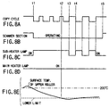
- FIGS. 8A to 8D are timing charts explaining another scheme of controlling the lamps 62 and 63 of the fixing device 46 in the continuous copying mode.
- FIG. 8E is a chart, illustrating how the surface temperature of the upper roller 60 changes when the lamps 62 and 63 are controlled in this scheme. How the lamps 62 and 63 are controlled in this scheme will be explained below.
- the temperature control circuit 90 starts controlling the sub-heater lamp 63.
- the circuit 90 turns on the sub-heater lamp 63 at time t3 and turns off the sub-heater lamp 63 at time t4, while the first carriage 14 is returning to the initial position.
- the reading cycle of the of the scanner section 4 becomes shorter than in the control scheme illustrated in FIGS. 7A to 7E.
- the total power consumption of the digital copier 1 can be decreased to less than 15A, as is desired for use of household electric appliance.
- the sub-heater lamp is turned on upon lapse of a specific time after the main heater lamp is turned on, said specific time being the time that the rush current in the main heater lamp takes to decrease to a constant value. More precisely, a lag of about 300 ms between the time of turning on the main heater lamp 62 and the time of turning on the sub-heater lamp 63.
- the instantaneous maximum value of the rush current can be much shorter than in the case where both the main heater lamp and the sub-heater lamp are turned on at the same time. An abrupt voltage drop that may result from a rush current can therefore be minimized.
- the reading cycle of the scanner section is increased when the surface temperature of the upper roller of the fixing device falls below the preset lower limit while document sheets are being scanned and read one after another.
- the surface temperature of the upper roller can therefore be maintained at an appropriate value.
Abstract
Description
Claims (10)
- An image forming apparatus comprising reading means (4) having an exposure lamp (10), for reading an image from a document by turning on the exposure lamp (10), processing means (34, 38) for forming an electrostatic latent image corresponding to the image read by the reading means (4) on an image-holding body (30), developing the electrostatic latent image on the image-holding body (30) with toner, thereby forming a toner image, and transferring the toner image to an image-recording medium, and fixing means (46) having a fixing roller (60) incorporating first and second heater lamps (62, 63), for fixing the toner image on the image-recording medium, characterized by further comprising:first control means (90, FIG. 6B) for turning off one of the first and second heater lamps (62, 63) when the exposure lamp (10) of the reading means (4) is turned on; andsecond control means (90, FIG. 6B) for turning on both the first heater lamp (62) and the second heater mean (63) after the reading means (4) finishes scanning and reading the document, thereby to maintaining a surface temperature of the fixing roller (60) within a predetermined range.
- An apparatus according to claim 1, characterized in that the second control means turns on the first and second heater lamps (62, 63) with a predetermined time lag, thereby to decrease a rush current.
- An apparatus according to claim 2, wherein the predetermined time lag is substantially 300 ms (FIG. 5).
- An apparatus according to claim 1, further comprising third control means (80, FIG. 7A) for controlling the reading means to increase a document-reading cycle of the reading means when the surface temperature of the fixing roller falls below a lower limit of the predetermined range during a continuous copying operation.
- An apparatus according to claim 1, characterized in that the reading means (4) includes first drive means (80, 14) for moving the exposure lamp (10) in a sub-scanning direction, and second drive means (80, 14) for moving the exposure lamp to an initial position in a direction opposite to the sub-scanning direction, and third control means (80, FIG. 7A) is further provided for controlling the reading means to decrease a speed with which the exposure lamp is moved to the initial position, when the surface temperature of the fixing roller falls below a lower limit of the predetermined range during a continuous copying operation.
- An apparatus according to claim 1, characterized in that the reading means includes first drive means (80, 14) for moving the exposure lamp (10) in a sub-scanning direction, and second drive means (80, 14) for moving the exposure lamp to an initial position in a direction opposite to the sub-scanning direction, and which further comprises third control means (80, FIG. 7A) for controlling the reading means to decrease a speed with which the exposure lamp is moved to the initial position, when the surface temperature of the fixing roller falls below a lower limit of the predetermined range during a continuous copying operation.
- A method of operating an image forming apparatus including reading section (4) having an exposure lamp (10), for reading an image from a document by turning on the exposure lamp (10), processing section (34, 38) for forming an electrostatic latent image corresponding to the image read by the reading section (4) on an image-holding body (30), developing the electrostatic latent image on the image-holding body (30) with toner, thereby forming a toner image, and transferring the toner image to an image-recording medium, and fixing section (46) having a fixing roller (60) incorporating first and second heater lamps (62, 63), for fixing the toner image on the image-recording medium, characterized by comprising:a first control step (90, FIG. 6B) of turning off one of the first and second heater lamps (62, 63) when the exposure lamp (10) of the reading section (4) is turned on; anda second step (90, FIG. 6B) of turning on both the first heater lamp (62) and the second heater lamp (63) after the reading section (4) finishes scanning and reading the document, thereby to maintaining a surface temperature of the fixing roller (60) within a predetermined range.
- A method according to claim 7, characterized in that the second control step includes a step of turning on the second the first and second heater lamps (62, 63) with a predetermined time lag, thereby to decrease a rush current.
- A method according to claim 8, characterized in that the predetermined time lag is substantially 300 ms (FIG. 5).
- A method according to claim 7, characterized in that the reading section (4) reads the document while the exposure lamp is being moved first in a sub-scanning direction, and then to an initial position in a direction opposite to the sub-scanning direction, and which further comprises a step of controlling the reading section to decrease a speed with which the exposure lamp is moved to the initial position, when the surface temperature of the fixing roller falls below a lower limit of the predetermined range during a continuous copying operation.
Applications Claiming Priority (2)
| Application Number | Priority Date | Filing Date | Title |
|---|---|---|---|
| JP22804698 | 1998-08-12 | ||
| JP10228046A JP2000056615A (en) | 1998-08-12 | 1998-08-12 | Image forming device |
Publications (2)
| Publication Number | Publication Date |
|---|---|
| EP0980180A2 true EP0980180A2 (en) | 2000-02-16 |
| EP0980180A3 EP0980180A3 (en) | 2001-02-07 |
Family
ID=16870362
Family Applications (1)
| Application Number | Title | Priority Date | Filing Date |
|---|---|---|---|
| EP99115833A Withdrawn EP0980180A3 (en) | 1998-08-12 | 1999-08-11 | Image forming apparatus |
Country Status (3)
| Country | Link |
|---|---|
| US (1) | US6141511A (en) |
| EP (1) | EP0980180A3 (en) |
| JP (1) | JP2000056615A (en) |
Families Citing this family (5)
| Publication number | Priority date | Publication date | Assignee | Title |
|---|---|---|---|---|
| JP4944310B2 (en) * | 2001-05-29 | 2012-05-30 | キヤノン株式会社 | Image forming apparatus |
| US6934483B2 (en) * | 2002-02-28 | 2005-08-23 | Matsushita Electric Industrial Co., Ltd. | Image heating device, image forming apparatus, image copying machine, and method for controlling temperature |
| US6968137B2 (en) * | 2002-02-28 | 2005-11-22 | Matsushita Electric Industrial Co., Ltd. | Image heating device, image forming apparatus, image copying machine, and method for controlling temperature |
| US6757503B2 (en) * | 2002-10-30 | 2004-06-29 | Kabushiki Kaisha Toshiba | Fixing device in an image forming apparatus having multiple heater lamps |
| KR100696103B1 (en) * | 2005-08-16 | 2007-03-19 | 삼성전자주식회사 | Image forming apparatus and fixing apparatus |
Citations (7)
| Publication number | Priority date | Publication date | Assignee | Title |
|---|---|---|---|---|
| JPS60123878A (en) * | 1983-12-09 | 1985-07-02 | Sharp Corp | Heat fixing device |
| JPS61169867A (en) * | 1985-01-22 | 1986-07-31 | Sharp Corp | Operation control method of copying machine |
| JPS62157073A (en) * | 1985-12-28 | 1987-07-13 | Ricoh Co Ltd | Heat fixing device for copying machine or the like |
| US4951160A (en) * | 1988-07-05 | 1990-08-21 | Ricoh Company, Ltd. | Image reproducing apparatus |
| US5040075A (en) * | 1990-10-10 | 1991-08-13 | Fuji Xerox Co., Ltd. | Digital electrophotographic copying apparatus |
| EP0804014A1 (en) * | 1996-04-26 | 1997-10-29 | Konica Corporation | Variable resolution laser printer |
| JPH10186940A (en) * | 1996-12-24 | 1998-07-14 | Canon Inc | Heater controller |
Family Cites Families (6)
| Publication number | Priority date | Publication date | Assignee | Title |
|---|---|---|---|---|
| JPS58130368A (en) * | 1982-12-23 | 1983-08-03 | Canon Inc | Heating method of fixing device |
| JPS61277986A (en) * | 1985-05-31 | 1986-12-08 | Mita Ind Co Ltd | Fixing device |
| JPH0232374A (en) * | 1988-07-21 | 1990-02-02 | Canon Inc | Image forming device |
| JPH07261596A (en) * | 1994-03-24 | 1995-10-13 | Toshiba Corp | Image forming device |
| US5526103A (en) * | 1994-03-31 | 1996-06-11 | Minolta Co., Ltd. | Induction heating fixing device |
| US5809369A (en) * | 1995-10-30 | 1998-09-15 | Fuji Xerox Co., Ltd. | Image formation system |
-
1998
- 1998-08-12 JP JP10228046A patent/JP2000056615A/en active Pending
-
1999
- 1999-08-11 EP EP99115833A patent/EP0980180A3/en not_active Withdrawn
- 1999-08-12 US US09/372,683 patent/US6141511A/en not_active Expired - Fee Related
Patent Citations (7)
| Publication number | Priority date | Publication date | Assignee | Title |
|---|---|---|---|---|
| JPS60123878A (en) * | 1983-12-09 | 1985-07-02 | Sharp Corp | Heat fixing device |
| JPS61169867A (en) * | 1985-01-22 | 1986-07-31 | Sharp Corp | Operation control method of copying machine |
| JPS62157073A (en) * | 1985-12-28 | 1987-07-13 | Ricoh Co Ltd | Heat fixing device for copying machine or the like |
| US4951160A (en) * | 1988-07-05 | 1990-08-21 | Ricoh Company, Ltd. | Image reproducing apparatus |
| US5040075A (en) * | 1990-10-10 | 1991-08-13 | Fuji Xerox Co., Ltd. | Digital electrophotographic copying apparatus |
| EP0804014A1 (en) * | 1996-04-26 | 1997-10-29 | Konica Corporation | Variable resolution laser printer |
| JPH10186940A (en) * | 1996-12-24 | 1998-07-14 | Canon Inc | Heater controller |
Also Published As
| Publication number | Publication date |
|---|---|
| JP2000056615A (en) | 2000-02-25 |
| US6141511A (en) | 2000-10-31 |
| EP0980180A3 (en) | 2001-02-07 |
Similar Documents
| Publication | Publication Date | Title |
|---|---|---|
| US7203435B2 (en) | Image forming apparatus and printer having a double-sided printing mode | |
| JP4485833B2 (en) | Fixing device, image forming apparatus | |
| US7606509B2 (en) | Image forming apparatus, recording material conveying method, program for implementing the method, and storage medium storing the program | |
| US5745247A (en) | Image forming apparatus having a controlled fixing unit | |
| US6587654B1 (en) | Image forming apparatus | |
| JP3720725B2 (en) | Image forming apparatus | |
| US6141511A (en) | Fixing device for use in an image forming apparatus that has first and second heater lamps and first and second controllers | |
| US6973275B2 (en) | Image forming device | |
| US20020067928A1 (en) | Image forming apparatus | |
| US20040264986A1 (en) | Image forming device | |
| JP4155556B2 (en) | Image forming apparatus | |
| JP4241308B2 (en) | Image forming apparatus | |
| JP2000039800A (en) | Image forming device | |
| JPH07199721A (en) | Image forming device | |
| JP2003186342A (en) | Image forming apparatus and image forming method | |
| JP4031920B2 (en) | Image forming apparatus | |
| JPH09294207A (en) | Image reader and image forming device | |
| JP2003149990A (en) | Image forming device | |
| JP2001083836A (en) | Image forming device | |
| JP2007013907A (en) | Image reading apparatus, and image forming apparatus | |
| JP2003173104A (en) | Method for controlling heating of fixing device in image forming apparatus | |
| JP2007156179A (en) | Temperature controller | |
| JPH0934241A (en) | Image forming device | |
| JP2008046340A (en) | Fixation control method and unit, and image forming apparatus | |
| JPH0990804A (en) | Image forming device |
Legal Events
| Date | Code | Title | Description |
|---|---|---|---|
| PUAI | Public reference made under article 153(3) epc to a published international application that has entered the european phase |
Free format text: ORIGINAL CODE: 0009012 |
|
| 17P | Request for examination filed |
Effective date: 19990811 |
|
| AK | Designated contracting states |
Kind code of ref document: A2 Designated state(s): DE FR GB |
|
| AX | Request for extension of the european patent |
Free format text: AL;LT;LV;MK;RO;SI |
|
| PUAL | Search report despatched |
Free format text: ORIGINAL CODE: 0009013 |
|
| AK | Designated contracting states |
Kind code of ref document: A3 Designated state(s): AT BE CH CY DE DK ES FI FR GB GR IE IT LI LU MC NL PT SE |
|
| AX | Request for extension of the european patent |
Free format text: AL;LT;LV;MK;RO;SI |
|
| AKX | Designation fees paid |
Free format text: DE FR GB |
|
| 17Q | First examination report despatched |
Effective date: 20050428 |
|
| 17Q | First examination report despatched |
Effective date: 20050428 |
|
| STAA | Information on the status of an ep patent application or granted ep patent |
Free format text: STATUS: THE APPLICATION IS DEEMED TO BE WITHDRAWN |
|
| 18D | Application deemed to be withdrawn |
Effective date: 20070301 |