EP0984083B1 - Omega spray pattern and method therefor - Google Patents
Omega spray pattern and method therefor Download PDFInfo
- Publication number
- EP0984083B1 EP0984083B1 EP99306461A EP99306461A EP0984083B1 EP 0984083 B1 EP0984083 B1 EP 0984083B1 EP 99306461 A EP99306461 A EP 99306461A EP 99306461 A EP99306461 A EP 99306461A EP 0984083 B1 EP0984083 B1 EP 0984083B1
- Authority
- EP
- European Patent Office
- Prior art keywords
- fluid
- substrate
- shaped pattern
- separate
- fluid flow
- Prior art date
- Legal status (The legal status is an assumption and is not a legal conclusion. Google has not performed a legal analysis and makes no representation as to the accuracy of the status listed.)
- Expired - Lifetime
Links
Images
Classifications
-
- D—TEXTILES; PAPER
- D01—NATURAL OR MAN-MADE THREADS OR FIBRES; SPINNING
- D01D—MECHANICAL METHODS OR APPARATUS IN THE MANUFACTURE OF ARTIFICIAL FILAMENTS, THREADS, FIBRES, BRISTLES OR RIBBONS
- D01D5/00—Formation of filaments, threads, or the like
- D01D5/08—Melt spinning methods
-
- D—TEXTILES; PAPER
- D01—NATURAL OR MAN-MADE THREADS OR FIBRES; SPINNING
- D01D—MECHANICAL METHODS OR APPARATUS IN THE MANUFACTURE OF ARTIFICIAL FILAMENTS, THREADS, FIBRES, BRISTLES OR RIBBONS
- D01D5/00—Formation of filaments, threads, or the like
- D01D5/08—Melt spinning methods
- D01D5/098—Melt spinning methods with simultaneous stretching
- D01D5/0985—Melt spinning methods with simultaneous stretching by means of a flowing gas (e.g. melt-blowing)
-
- D—TEXTILES; PAPER
- D01—NATURAL OR MAN-MADE THREADS OR FIBRES; SPINNING
- D01D—MECHANICAL METHODS OR APPARATUS IN THE MANUFACTURE OF ARTIFICIAL FILAMENTS, THREADS, FIBRES, BRISTLES OR RIBBONS
- D01D4/00—Spinnerette packs; Cleaning thereof
- D01D4/02—Spinnerettes
- D01D4/025—Melt-blowing or solution-blowing dies
-
- Y—GENERAL TAGGING OF NEW TECHNOLOGICAL DEVELOPMENTS; GENERAL TAGGING OF CROSS-SECTIONAL TECHNOLOGIES SPANNING OVER SEVERAL SECTIONS OF THE IPC; TECHNICAL SUBJECTS COVERED BY FORMER USPC CROSS-REFERENCE ART COLLECTIONS [XRACs] AND DIGESTS
- Y10—TECHNICAL SUBJECTS COVERED BY FORMER USPC
- Y10T—TECHNICAL SUBJECTS COVERED BY FORMER US CLASSIFICATION
- Y10T428/00—Stock material or miscellaneous articles
- Y10T428/19—Sheets or webs edge spliced or joined
- Y10T428/192—Sheets or webs coplanar
- Y10T428/197—Sheets or webs coplanar with noncoplanar reinforcement
- Y10T428/198—Pile or nap surface sheets connected
-
- Y—GENERAL TAGGING OF NEW TECHNOLOGICAL DEVELOPMENTS; GENERAL TAGGING OF CROSS-SECTIONAL TECHNOLOGIES SPANNING OVER SEVERAL SECTIONS OF THE IPC; TECHNICAL SUBJECTS COVERED BY FORMER USPC CROSS-REFERENCE ART COLLECTIONS [XRACs] AND DIGESTS
- Y10—TECHNICAL SUBJECTS COVERED BY FORMER USPC
- Y10T—TECHNICAL SUBJECTS COVERED BY FORMER US CLASSIFICATION
- Y10T428/00—Stock material or miscellaneous articles
- Y10T428/24—Structurally defined web or sheet [e.g., overall dimension, etc.]
- Y10T428/24802—Discontinuous or differential coating, impregnation or bond [e.g., artwork, printing, retouched photograph, etc.]
- Y10T428/2481—Discontinuous or differential coating, impregnation or bond [e.g., artwork, printing, retouched photograph, etc.] including layer of mechanically interengaged strands, strand-portions or strand-like strips
-
- Y—GENERAL TAGGING OF NEW TECHNOLOGICAL DEVELOPMENTS; GENERAL TAGGING OF CROSS-SECTIONAL TECHNOLOGIES SPANNING OVER SEVERAL SECTIONS OF THE IPC; TECHNICAL SUBJECTS COVERED BY FORMER USPC CROSS-REFERENCE ART COLLECTIONS [XRACs] AND DIGESTS
- Y10—TECHNICAL SUBJECTS COVERED BY FORMER USPC
- Y10T—TECHNICAL SUBJECTS COVERED BY FORMER US CLASSIFICATION
- Y10T428/00—Stock material or miscellaneous articles
- Y10T428/28—Web or sheet containing structurally defined element or component and having an adhesive outermost layer
-
- Y—GENERAL TAGGING OF NEW TECHNOLOGICAL DEVELOPMENTS; GENERAL TAGGING OF CROSS-SECTIONAL TECHNOLOGIES SPANNING OVER SEVERAL SECTIONS OF THE IPC; TECHNICAL SUBJECTS COVERED BY FORMER USPC CROSS-REFERENCE ART COLLECTIONS [XRACs] AND DIGESTS
- Y10—TECHNICAL SUBJECTS COVERED BY FORMER USPC
- Y10T—TECHNICAL SUBJECTS COVERED BY FORMER US CLASSIFICATION
- Y10T428/00—Stock material or miscellaneous articles
- Y10T428/31504—Composite [nonstructural laminate]
- Y10T428/31551—Of polyamidoester [polyurethane, polyisocyanate, polycarbamate, etc.]
- Y10T428/31645—Next to addition polymer from unsaturated monomers
- Y10T428/31649—Ester, halide or nitrile of addition polymer
Definitions
- This invention relates generally to the dispensing of visco-elastic fluidic materials, and more particularly to methods for producing vacillating visco-elastic fibres for application onto substrates and elongated strands and combinations thereof.
- visco-elastic fibres or filaments which are deposited onto substrates and elongated strands moving relative thereto.
- These operations include the application of fiberized adhesives, including temperature and pressure sensitive adhesives, onto substrates and elongated strands for bonding to substrates.
- Other operations include the application of non-bonding fiberized visco-elastic materials onto various substrates as protective overlays, for example onto sheet-like articles which are stacked or packaged one on top of another, whereby the non-bonding fiberized material provides a protective overlay or separating member between the stacked articles.
- One exemplary bonding operation is the application of substantially continuous adhesive fibres onto woven and non-woven fabric substrates for bonding to other substrates and for bonding to overlapping portions of the same substrate in the manufacture of a variety of bodily fluid absorbing hygienic articles.
- the adhesive fibres may also be applied to elongated elastic strands for bonding to portions of the substrate, for example in the formation of elastic waist and leg band portions of diapers and other undergarments.
- Another exemplary adhesive fibre bonding operation is the bonding of paper substrates and overlapping portions of the same substrate in the manufacture of paper packaging, for example disposable paper sacks.
- melt blowing and spiral nozzles Conventional melt blowing and spiral nozzles however do not adequately satisfy all of the requirements in the manufacture of bodily fluid absorbing hygienic articles and other operations discussed generally above, or do so to a limited extent using adhesive excessively and inefficiently.
- Melt blowing nozzles generally dispense fibres chaotically in overlapping patterns, and spiral nozzles dispense fibres in overlapping spiral patterns. The fibre patterns produced by these conventional nozzles tend to stiffen the substrate, which is particularly undesirable in the manufacture of bodily fluid absorbing hygienic articles.
- the fibre patterns produced by conventional nozzles also tend to reduce the puffiness and hence softness of bonded substrates, or fabrics, which reduces the comfort thereof. Additionally, fibre patterns produced by conventional nozzles tend to reduce the absorbency of fabrics by obstructing the flow of moisture between layers, usually from the inner layers toward more absorbent outer layers. The conventional nozzles also apply fibres onto the substrate relatively non-uniformly, and lack precise control over where the fibres are applied onto substrates and elongated strands.
- the present invention is drawn toward advancements in the art of producing visco-elastic fluidic material flows, and more particularly to methods for producing vacillating visco-elastic fibres for application onto substrates and elongated strands, and combinations thereof. It is an object of the invention to provide novel methods for producing vacillating visco-elastic fluidic material flows for application onto various substrates and elongated strands and combinations thereof that go at least some way towards overcoming the above mentioned and problems in the art.
- a method for producing visco-elastic fluidic material flow comprises:
- an article of manufacture comprises:
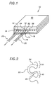
- Figure 1 shows an apparatus 10 for producing one or more visco-elastic fluidic material flows, or fibres, 20, which may be deposited onto substrates or elongate strands and which are useable in various bonding and non-bonding operations.
- the visco-elastic fluidic material is, for example, a polyethylene or polypropylene or other polymer formulated for bonding and/or non-bonding applications.
- These visco-elastic materials however are exemplary only, and are not intended to be limiting since any visco-elastic fluidic material that may be drawn into relatively continuous fibres or filaments are suitable for practicing the present invention.
- the visco-elastic fluidic material is a temperature or pressure sensitive adhesive useable for bonding overlapping substrates. These operations include, for example, applying adhesive fibres onto woven and non-woven substrates in the manufacture of bodily fluid absorbing hygienic articles, and onto paper substrates in the manufacture of paper packaging materials, and onto various other substrates, which are bonded with other substrates or with elongated strands.
- the visco-elastic fluidic material is a non-adhesive material deposited onto other substrates in non-bonding operations, for example as protective overlays between substrates, like glass and other materials.
- Figure 1 illustrates the nozzle 10 producing a visco-elastic fibre 20 in a repeating, generally omega-shaped pattern.
- Figure 2 illustrates a segment of the repeating, generally omega-shaped pattern having a bowed portion 22 with first and second side portions 24 and 26 each shared with corresponding adjacent bowed portions 32 and 42 of adjacent segments of the pattern, which are illustrated in phantom lines.
- the first and second side portions 24 and 26 first converge toward each other and then diverge outwardly in generally opposing directions before merging with the corresponding adjacent bowed portions 32 and 42.
- the repeating, generally omega-shaped pattern of the fibres 20 are produced remarkably consistently and uniformly, and are particularly well suited for many bonding and non-bonding operations with significant advantages over conventional overlapping chaotic and spiral fibre patterns produced by conventional nozzles.
- Any reference in this specification to "omega” (for example, “an omega-shaped pattern”) relate to the upper case Greek letter Omega ( ⁇ ).
- the repeating, generally omega-shaped pattern of the visco-elastic fibre 20 is produced generally by dispensing a visco-elastic fluidic material to form a first fluid flow 12 at a first velocity, and dispensing a second fluid to form separate second fluid flows 14 and 16 at a second velocity along generally opposing flanking sides of the first fluid flow 12.
- the separate second fluid flows 14 and 16 are located and oriented relative to the first fluid flow 12 to vacillate the first fluid flow 12 in a manner that produces the repeating, generally omega-shaped pattern.
- the second fluid flows 14 and 16 which are preferably a gas (for example air), are spaced from the first fluid flow 12 and dispensed at a second velocity greater than a first velocity of the first fluid flow 12 so that the first fluid flow 12 is drawn by the separate second fluid flows and vacillated to form the visco-elastic fibre in the repeating, generally omega-shaped pattern 20 illustrated in Figures 1 and 2 .
- the first fluid flow 12 and the separate second fluid flows 14 and 16 are preferably dispensed in a common plane, whereby the first fluid flow is vacillated to form the repeating generally omega-shaped pattern in the common plane containing the first and separate second fluid flows, illustrated best in Figure 1 .
- the separate second fluid flows 14 and 16 are converged toward the first fluid flow 12 to form the fibre in the repeating, generally omega-shaped pattern 20. And in another alternative mode of operation, the separate second fluid flows 14 and 16 are dispensed parallel to the first fluid flow 12 to form the fibre in the repeating, generally omega-shaped pattern 20.
- the first fluid flow 12 is correspondingly drawn increasingly and begins to vacillate back and forth with correspondingly increasing amplitude and frequency, as disclosed generally and more fully in the co-pending European Patent Application published as EP-A-872580 .
- the first fluid flow 12 begins to vacillate in the desired repeating, generally omega-shaped pattern 20.
- Figure 1 illustrates the visco-elastic fluidic material dispensed from a first orifice 52 in a body member 50, or die assembly, to form the first fluid flow 12, and the second fluid flow dispensed from two second orifices 54 and 56 in the body member 50 associated with the first orifice 52.
- the two second orifices 54 and 56 are disposed on generally opposing flanking sides of the first orifice 52, in a common plane, to form the separate second fluid flows 14 and 16 along generally opposing flanking sides of the first fluid flow 12.
- the body member 50 is preferably a parallel plate body member as disclosed generally and more fully in the above mentioned EP-A-872580 .
- the orifices of the parallel plate die assembly are generally rectangular. More particularly, the adhesive orifices are approximately 0.022 inches (0.056 cm) by approximately 0.030 inches (0.076 cm) and the corresponding separate air orifices are approximately 0.033 inches (0.084 cm) by approximately 0.030 inches (0.076 cm).
- the adhesive mass flow rate is approximately 10 grams per minute per adhesive orifice
- the air mass flow rate is approximately 0.114 cubic feet (3.23 litres) per minute for the two corresponding air orifices.
- a repeating, generally omega-shaped pattern having a width, or amplitude, of approximate 0. 25 inches (0.64 cm) is produced when the air pressure is between approximately 3 psi (20.7kPa) and approximately 10 psi (68.9 kPa), with a preferable operating air pressure of approximately 6 psi (41.4 kPa).
- the air temperature is generally the same as or greater than the adhesive temperature, and may be adjusted to control the adhesive temperature, which is usually specified by the manufacturer.
- exemplary die orifice specifications are not intended to be limiting, and may be varied considerably to produce the repeating, generally omega-shaped pattern.
- the orifices may be formed in more conventional non-parallel plate die assemblies, and may be circular rather than rectangular.
- the air and adhesive mass flow rates, as well as the air pressure required to produce the repeating, generally omega-shaped pattern may also be varied outside the exemplary ranges.
- the width of the amplitude and weight of the repeating, generally omega-shaped patterns 20 may be varied by appropriately selecting the air and adhesive orifice sizes and the controlling the air and adhesive mass flow rates.
- the amplitude of the repeating, generally omega-shaped pattern is generally between approximately 0.125 (0.318 cm) and 1 inches (2.54 cm), but may be more or less.
- a body member 50, or die assembly, configured and operated as discussed above produces remarkably uniform and consistent repeating, generally omega-shaped pattern 20. Additionally, the amplitude and frequency of the repeating, generally omega-shaped patterns 20 may be controlled relatively precisely as discussed above and more fully in the above mentioned EP-A-872580 . Thus the repeating, generally omega-shaped pattern may be deposited onto a substrate or elongated strand with substantial uniformity and accuracy not heretofore available with conventional fibre or filament dispensing nozzles.
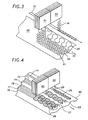
- Figure 3 illustrates a first parallel plate die assembly 51 having nozzles for depositing multiple repeating, generally omega-shaped patterns 20 with differing amplitudes onto a substrate 60 moving relative thereto in a substrate coating operation.
- An alternative and equivalent is for the die assembly 51 to move relative to a fixed substrate.
- the first fluid flows forming the repeating, generally omega-shaped patterns 20 are vacillated non-parallel to the movement direction of the substrate by the corresponding second fluid flows, and more particularly the first fluid flows are vacillated transversely to the movement direction of the substrate 60.
- the repeating, generally omega-shaped patterns 20 may be deposited relatively continuously onto a surface of the substrate in single or multiple parallel patterns, which selectively cover the substrate as desired for the particular application.
- two or more repeating, generally omega-shaped patterns 35, 36 and 37 may be applied to the substrate 60 side-by-side providing relatively complete substrate coverage without undesirable overlapping there between.
- the extent of the overlap can be controlled relatively precisely in the practice of the present invention. This is due in part to the relatively consistent width of the fibres 20 produced, and also to the location accuracy with which the fibres 20 are applied onto the substrate.
- Figures 3 and 4 illustrate also how the repeating, generally omega-shaped fibre patterns 20 provide excellent bonding without compromising absorbency and softness of the substrate, which is so desirable when bonding woven and non-woven fabric substrates in the manufacture of bodily fluid absorbing hygienic articles. More particularly, the repeating, generally omega-shaped fibre patterns 20 provide uniform substrate coverage with substantial adhesive bonding area, yet fibre overlapping is eliminated or at least reduced substantially where undesired. Thus the tendency of the fabric to stiffen due to globular and overlapping fibres is eliminated. The repeating, generally omega-shaped fibre patterns 20 also provide relatively large areas of adhesive non-coverage through which bodily fluids may flow unobstructed. These large areas of adhesive non-coverage also reduce the tendency of the woven and non-woven fabric substrates to flatten and lose puffiness, which otherwise occurs with fibres produced by conventional nozzles, thereby increasing the softness of the bonded substrates.
- Figure 3 also illustrates a second parallel plate die assembly 53 depositing a repeating, generally omega-shaped fibre pattern 34 onto at least one isolated elongated strand 70 moving relative thereto in a strand coating operation.
- An alternative and equivalent is for the die assembly 53 to move relative to a fixed strand.
- the repeating, generally omega-shaped pattern is vacillated generally non-parallel, and in the exemplary operation transversely to, a direction of movement of the isolated elongated strand 70.
- the uniformity and consistency of the repeating, general omega-shape pattern ensures relatively uniform application thereof along the axial dimension of the elongated strand, which is particularly desirable in operations where the strand is a stretched elongated elastic strand subsequently bonded to some other substrate, thereby reducing the tendency of the bonded elongated strand 70 to thereafter creep relative to the substrate 60 when severed during subsequent fabrication operations.
- at least one repeating, generally omega-shaped fibre pattern may be deposited onto two or more isolated elongated strands moving relative thereto in a strand coating operation.
- multiple adjacent or overlapping repeating, generally omega-shaped fibre patterns may be deposited onto two or more isolated elongated strands moving relative thereto in a strand coating operation.
- the amplitude or width of the repeating, generally omega-shaped pattern 34 is selected so that substantially all of the visco-elastic material vacillating in the repeating, generally omega-shaped pattern is captured on or about an isolated elongated strand 70 as disclosed generally and more fully in the co-pending European Patent Application number 99105750.6 filed on 15 March 1999 .
- the uniform width of the repeating, generally omega-shaped pattern 34 and the accuracy with which it is deposited makes possible the capture of substantially all of the fibre 34 onto the elongated strand 70, which is highly desirable in manufacturing operations and is a significant advantage over conventional elongated strand bonding operations.
- Figure 4 illustrates another alternative operation wherein a repeating, generally omega-shaped fibre pattern 25 is deposited onto at least one corresponding elongated strand 71, which may be a stretched elongated elastic strand, disposed either directly on the substrate 60, or raised thereabove.
- the uniformity and consistency of the repeating, generally omega-shaped pattern ensures relatively uniform application thereof along the axial dimension of the at least one elongated strand 71.
- the amplitude or width of the repeating, generally omega-shaped pattern 25 may be selected so that the repeating, generally omega-shaped fibre pattern just covers the elongated strand 71 widthwise, for example in a bonding operation whereby the fibre is an adhesive material, so that the elongated strand 71 is effectively stitched to the substrate 60.
- a single repeating, generally omega-shaped pattern 29 may be deposited onto two or more elongated strands 72 and 74 disposed either directly on the substrate 60, or raised thereabove.
- two or more repeating, generally omega-shaped patterns 27 and 28 may be deposited, either adjacently or overlappingly, as illustrated, onto multiple elongated strands 76, 77 and 78 disposed either directly on the substrate 60, or raised thereabove.
- the width and weight of the repeating, generally omega-shaped fibre patterns, and the location of deposition thereof onto the strand and/or substrate depends on the configuration of the die assembly 50 as discussed herein above.
Abstract
Description
- This invention relates generally to the dispensing of visco-elastic fluidic materials, and more particularly to methods for producing vacillating visco-elastic fibres for application onto substrates and elongated strands and combinations thereof.
- It is desirable in many manufacturing operations to form visco-elastic fibres or filaments, which are deposited onto substrates and elongated strands moving relative thereto. These operations include the application of fiberized adhesives, including temperature and pressure sensitive adhesives, onto substrates and elongated strands for bonding to substrates. Other operations include the application of non-bonding fiberized visco-elastic materials onto various substrates as protective overlays, for example onto sheet-like articles which are stacked or packaged one on top of another, whereby the non-bonding fiberized material provides a protective overlay or separating member between the stacked articles.
- One exemplary bonding operation is the application of substantially continuous adhesive fibres onto woven and non-woven fabric substrates for bonding to other substrates and for bonding to overlapping portions of the same substrate in the manufacture of a variety of bodily fluid absorbing hygienic articles. The adhesive fibres may also be applied to elongated elastic strands for bonding to portions of the substrate, for example in the formation of elastic waist and leg band portions of diapers and other undergarments. Another exemplary adhesive fibre bonding operation is the bonding of paper substrates and overlapping portions of the same substrate in the manufacture of paper packaging, for example disposable paper sacks.
- In many adhesive fibre bonding operations, including the exemplary bodily fluid absorbing hygienic article and paper packaging manufacturing operations, as well as many non-bonding operations, it is desirable to uniformly apply the visco-elastic fibres onto the substrate and to accurately control where on the substrate the visco-elastic fibres are applied. The uniform application of visco-elastic fibres onto substrates and elongated strands ensures consistent bonding between substrates, or overlapping layer portions thereof, and elongated strands. The uniform application of visco-elastic fibres onto substrates and elongated strands also economizes usage thereof. Accurately controlling where the visco-elastic fibres are applied onto the substrate ensures proper and complete bonding in areas where bonding is desired, provides a distinct interface between areas of bonding and non-bonding, and generally reduces substrate waste resulting from visco-elastic fibres applied uncontrollably to areas thereof outside or beyond the desired target or bonding areas.
- In the manufacture of bodily fluid absorbing hygienic articles, it is desirable to provide maximum absorbency and softness of overlapping bonded substrates and at the same time provide effective bonding therebetween. It is also desirable to bond stretched elongated elastic strands relatively continuously along the axial length thereof for bonding onto substrates so that the stretched strands do not slip, or creep, relative to the substrate when the substrate and strand are later severed in subsequent fabrication operations. More generally, it is desirable to accurately and uniformly apply visco-elastic fibres onto substrates and elongated strands, without undesirable overlapping of adjacent fibres, and with well defined, or distinct, interfaces between substrate areas with and without fibre coverage. Similar results are desirable in the application of bonding and non-bonding fibres onto substrates and elongated strands used in operations besides the exemplary manufacture of hygienic articles.
- In the past, visco-elastic fibres have been applied onto substrates with melt blowing and spiral nozzles. Conventional melt blowing and spiral nozzles however do not adequately satisfy all of the requirements in the manufacture of bodily fluid absorbing hygienic articles and other operations discussed generally above, or do so to a limited extent using adhesive excessively and inefficiently. Melt blowing nozzles generally dispense fibres chaotically in overlapping patterns, and spiral nozzles dispense fibres in overlapping spiral patterns. The fibre patterns produced by these conventional nozzles tend to stiffen the substrate, which is particularly undesirable in the manufacture of bodily fluid absorbing hygienic articles. The fibre patterns produced by conventional nozzles also tend to reduce the puffiness and hence softness of bonded substrates, or fabrics, which reduces the comfort thereof. Additionally, fibre patterns produced by conventional nozzles tend to reduce the absorbency of fabrics by obstructing the flow of moisture between layers, usually from the inner layers toward more absorbent outer layers. The conventional nozzles also apply fibres onto the substrate relatively non-uniformly, and lack precise control over where the fibres are applied onto substrates and elongated strands.
- The present invention is drawn toward advancements in the art of producing visco-elastic fluidic material flows, and more particularly to methods for producing vacillating visco-elastic fibres for application onto substrates and elongated strands, and combinations thereof. It is an object of the invention to provide novel methods for producing vacillating visco-elastic fluidic material flows for application onto various substrates and elongated strands and combinations thereof that go at least some way towards overcoming the above mentioned and problems in the art.
- According to a first aspect of this invention a method for producing visco-elastic fluidic material flow comprises:
- dispensing the visco-elastic fluidic material to form a first fluid flow at a first velocity;
- dispensing a second fluid to form separate second fluid flows at a second velocity along generally opposing flanking sides of the first fluid flow; and
- vacillating the first fluid flow with the separate second fluid flows to form a repeating generally omega-shaped pattern, the generally omega-shaped pattern having a bowed portion with first and second side portions, the first and second side portions converging toward each other and then diverging outwardly in generally opposing directions.
- According to a further aspect of this invention an article of manufacture comprises:
- a substrate having a first surface; and
- a substantially continuous visco-elastic fibre disposed on the first surface of the substrate, the substantially continuous visco-elastic fibre formed in a repeating generally omega-shaped pattern, the generally omega-shaped pattern having a bowed portion with first and second side portions, the first and second side portions converging toward each other and then diverging outwardly in generally opposing directions.
- A particular embodiment of the present invention will now be described with reference to the accompanying drawings in which:
-
Figure 1 is a perspective view of an apparatus for producing a visco-elastic fibre vacillating in a repeating, generally omega-shaped pattern according to a particular embodiment of the present invention; -
Figure 2 is a partial view of the repeating, generally omega-shaped visco-elastic fibre pattern produced by the apparatus ofFigure 1 ; -
Figure 3 is an exemplary application of the visco-elastic fibres ofFigure 2 onto a substrate and an elongated strand; and -
Figure 4 is another exemplary application of the visco-elastic fibres ofFigure 2 onto substrates and elongated strands. -
Figure 1 shows anapparatus 10 for producing one or more visco-elastic fluidic material flows, or fibres, 20, which may be deposited onto substrates or elongate strands and which are useable in various bonding and non-bonding operations. The visco-elastic fluidic material is, for example, a polyethylene or polypropylene or other polymer formulated for bonding and/or non-bonding applications. These visco-elastic materials however are exemplary only, and are not intended to be limiting since any visco-elastic fluidic material that may be drawn into relatively continuous fibres or filaments are suitable for practicing the present invention. - In one exemplary operation, the visco-elastic fluidic material is a temperature or pressure sensitive adhesive useable for bonding overlapping substrates. These operations include, for example, applying adhesive fibres onto woven and non-woven substrates in the manufacture of bodily fluid absorbing hygienic articles, and onto paper substrates in the manufacture of paper packaging materials, and onto various other substrates, which are bonded with other substrates or with elongated strands. In another exemplary application, the visco-elastic fluidic material is a non-adhesive material deposited onto other substrates in non-bonding operations, for example as protective overlays between substrates, like glass and other materials.
-
Figure 1 illustrates thenozzle 10 producing a visco-elastic fibre 20 in a repeating, generally omega-shaped pattern.Figure 2 illustrates a segment of the repeating, generally omega-shaped pattern having a bowedportion 22 with first andsecond side portions bowed portions second side portions bowed portions fibres 20 are produced remarkably consistently and uniformly, and are particularly well suited for many bonding and non-bonding operations with significant advantages over conventional overlapping chaotic and spiral fibre patterns produced by conventional nozzles. Any reference in this specification to "omega" (for example, "an omega-shaped pattern") relate to the upper case Greek letter Omega (Ω). - In
Figure 1 , the repeating, generally omega-shaped pattern of the visco-elastic fibre 20 is produced generally by dispensing a visco-elastic fluidic material to form afirst fluid flow 12 at a first velocity, and dispensing a second fluid to form separate second fluid flows 14 and 16 at a second velocity along generally opposing flanking sides of thefirst fluid flow 12. The separate second fluid flows 14 and 16 are located and oriented relative to thefirst fluid flow 12 to vacillate thefirst fluid flow 12 in a manner that produces the repeating, generally omega-shaped pattern. - The second fluid flows 14 and 16, which are preferably a gas (for example air), are spaced from the
first fluid flow 12 and dispensed at a second velocity greater than a first velocity of thefirst fluid flow 12 so that thefirst fluid flow 12 is drawn by the separate second fluid flows and vacillated to form the visco-elastic fibre in the repeating, generally omega-shaped pattern 20 illustrated inFigures 1 and 2 . Thefirst fluid flow 12 and the separate second fluid flows 14 and 16 are preferably dispensed in a common plane, whereby the first fluid flow is vacillated to form the repeating generally omega-shaped pattern in the common plane containing the first and separate second fluid flows, illustrated best inFigure 1 . In one mode of operation, the separate second fluid flows 14 and 16 are converged toward thefirst fluid flow 12 to form the fibre in the repeating, generally omega-shaped pattern 20. And in another alternative mode of operation, the separate second fluid flows 14 and 16 are dispensed parallel to thefirst fluid flow 12 to form the fibre in the repeating, generally omega-shaped pattern 20. - Generally, as the second velocity of the separate second fluids flows 14 and 16 increases relative to the first velocity of the
first fluid flow 12, thefirst fluid flow 12 is correspondingly drawn increasingly and begins to vacillate back and forth with correspondingly increasing amplitude and frequency, as disclosed generally and more fully in the co-pending European Patent Application published asEP-A-872580 first fluid flow 12, thefirst fluid flow 12 begins to vacillate in the desired repeating, generally omega-shaped pattern 20. Further increases in the second velocity of the separate second fluid flows 14 and 16 relative to the first velocity of thefirst fluid flow 12 eventually results in a generally chaotic vacillation of the visco-elastic fibre, which may be desirable for some operations but is beyond the scope of the present application. -
Figure 1 illustrates the visco-elastic fluidic material dispensed from afirst orifice 52 in abody member 50, or die assembly, to form thefirst fluid flow 12, and the second fluid flow dispensed from twosecond orifices body member 50 associated with thefirst orifice 52. The twosecond orifices first orifice 52, in a common plane, to form the separate second fluid flows 14 and 16 along generally opposing flanking sides of thefirst fluid flow 12. Thebody member 50 is preferably a parallel plate body member as disclosed generally and more fully in the above mentionedEP-A-872580 - In one exemplary adhesive dispensing operation suitable for the manufacture of bodily fluid absorbing hygienic articles, the orifices of the parallel plate die assembly are generally rectangular. More particularly, the adhesive orifices are approximately 0.022 inches (0.056 cm) by approximately 0.030 inches (0.076 cm) and the corresponding separate air orifices are approximately 0.033 inches (0.084 cm) by approximately 0.030 inches (0.076 cm). In the exemplary adhesive dispensing operation, the adhesive mass flow rate is approximately 10 grams per minute per adhesive orifice, and the air mass flow rate is approximately 0.114 cubic feet (3.23 litres) per minute for the two corresponding air orifices. Under these exemplary operating conditions, a repeating, generally omega-shaped pattern having a width, or amplitude, of approximate 0. 25 inches (0.64 cm) is produced when the air pressure is between approximately 3 psi (20.7kPa) and approximately 10 psi (68.9 kPa), with a preferable operating air pressure of approximately 6 psi (41.4 kPa). The air temperature is generally the same as or greater than the adhesive temperature, and may be adjusted to control the adhesive temperature, which is usually specified by the manufacturer.
- These exemplary die orifice specifications are not intended to be limiting, and may be varied considerably to produce the repeating, generally omega-shaped pattern. The orifices may be formed in more conventional non-parallel plate die assemblies, and may be circular rather than rectangular. The air and adhesive mass flow rates, as well as the air pressure required to produce the repeating, generally omega-shaped pattern may also be varied outside the exemplary ranges. For example, the width of the amplitude and weight of the repeating, generally omega-shaped
patterns 20 may be varied by appropriately selecting the air and adhesive orifice sizes and the controlling the air and adhesive mass flow rates. For many adhesive dispensing operations the amplitude of the repeating, generally omega-shaped pattern is generally between approximately 0.125 (0.318 cm) and 1 inches (2.54 cm), but may be more or less. - A
body member 50, or die assembly, configured and operated as discussed above produces remarkably uniform and consistent repeating, generally omega-shapedpattern 20. Additionally, the amplitude and frequency of the repeating, generally omega-shapedpatterns 20 may be controlled relatively precisely as discussed above and more fully in the above mentionedEP-A-872580 -
Figure 3 illustrates a first parallel plate dieassembly 51 having nozzles for depositing multiple repeating, generally omega-shapedpatterns 20 with differing amplitudes onto asubstrate 60 moving relative thereto in a substrate coating operation. An alternative and equivalent is for thedie assembly 51 to move relative to a fixed substrate. In the exemplary embodiment, the first fluid flows forming the repeating, generally omega-shapedpatterns 20 are vacillated non-parallel to the movement direction of the substrate by the corresponding second fluid flows, and more particularly the first fluid flows are vacillated transversely to the movement direction of thesubstrate 60. This aspect of the invention is disclosed more fully in the above mentionedEP-A-872580 - According to the present invention, the repeating, generally omega-shaped
patterns 20 may be deposited relatively continuously onto a surface of the substrate in single or multiple parallel patterns, which selectively cover the substrate as desired for the particular application. InFigure 3 for example, two or more repeating, generally omega-shapedpatterns substrate 60 side-by-side providing relatively complete substrate coverage without undesirable overlapping there between. And in operations where some overlapping ofadjacent fibre patterns 20 is desired, the extent of the overlap can be controlled relatively precisely in the practice of the present invention. This is due in part to the relatively consistent width of thefibres 20 produced, and also to the location accuracy with which thefibres 20 are applied onto the substrate. -
Figures 3 and 4 illustrate also how the repeating, generally omega-shapedfibre patterns 20 provide excellent bonding without compromising absorbency and softness of the substrate, which is so desirable when bonding woven and non-woven fabric substrates in the manufacture of bodily fluid absorbing hygienic articles. More particularly, the repeating, generally omega-shapedfibre patterns 20 provide uniform substrate coverage with substantial adhesive bonding area, yet fibre overlapping is eliminated or at least reduced substantially where undesired. Thus the tendency of the fabric to stiffen due to globular and overlapping fibres is eliminated. The repeating, generally omega-shapedfibre patterns 20 also provide relatively large areas of adhesive non-coverage through which bodily fluids may flow unobstructed. These large areas of adhesive non-coverage also reduce the tendency of the woven and non-woven fabric substrates to flatten and lose puffiness, which otherwise occurs with fibres produced by conventional nozzles, thereby increasing the softness of the bonded substrates. -
Figure 3 also illustrates a second parallel plate dieassembly 53 depositing a repeating, generally omega-shapedfibre pattern 34 onto at least one isolatedelongated strand 70 moving relative thereto in a strand coating operation. An alternative and equivalent is for thedie assembly 53 to move relative to a fixed strand. According to the strand coating operation, the repeating, generally omega-shaped pattern is vacillated generally non-parallel, and in the exemplary operation transversely to, a direction of movement of the isolatedelongated strand 70. The uniformity and consistency of the repeating, general omega-shape pattern ensures relatively uniform application thereof along the axial dimension of the elongated strand, which is particularly desirable in operations where the strand is a stretched elongated elastic strand subsequently bonded to some other substrate, thereby reducing the tendency of the bondedelongated strand 70 to thereafter creep relative to thesubstrate 60 when severed during subsequent fabrication operations. More generally, at least one repeating, generally omega-shaped fibre pattern may be deposited onto two or more isolated elongated strands moving relative thereto in a strand coating operation. Alternatively, multiple adjacent or overlapping repeating, generally omega-shaped fibre patterns may be deposited onto two or more isolated elongated strands moving relative thereto in a strand coating operation. - In one operation, the amplitude or width of the repeating, generally omega-shaped
pattern 34 is selected so that substantially all of the visco-elastic material vacillating in the repeating, generally omega-shaped pattern is captured on or about an isolatedelongated strand 70 as disclosed generally and more fully in the co-pending European Patent Application number99105750.6 filed on 15 March 1999 pattern 34 and the accuracy with which it is deposited makes possible the capture of substantially all of thefibre 34 onto theelongated strand 70, which is highly desirable in manufacturing operations and is a significant advantage over conventional elongated strand bonding operations. -
Figure 4 illustrates another alternative operation wherein a repeating, generally omega-shapedfibre pattern 25 is deposited onto at least one correspondingelongated strand 71, which may be a stretched elongated elastic strand, disposed either directly on thesubstrate 60, or raised thereabove. The uniformity and consistency of the repeating, generally omega-shaped pattern ensures relatively uniform application thereof along the axial dimension of the at least oneelongated strand 71. Also, the amplitude or width of the repeating, generally omega-shapedpattern 25 may be selected so that the repeating, generally omega-shaped fibre pattern just covers theelongated strand 71 widthwise, for example in a bonding operation whereby the fibre is an adhesive material, so that theelongated strand 71 is effectively stitched to thesubstrate 60. - In another operation, a single repeating, generally omega-shaped
pattern 29 may be deposited onto two or moreelongated strands substrate 60, or raised thereabove. And in other operations, two or more repeating, generally omega-shapedpatterns elongated strands substrate 60, or raised thereabove. The width and weight of the repeating, generally omega-shaped fibre patterns, and the location of deposition thereof onto the strand and/or substrate of course, depends on the configuration of thedie assembly 50 as discussed herein above. - While the foregoing written description of the invention enables one of ordinary skill to make and use what is considered presently to be the best mode thereof, those of ordinary skill will understand and appreciate the existence of variations, combinations, and equivalents of the specific exemplary embodiments herein. The invention is therefore to be limited not by the exemplary embodiments herein, but by all embodiments within the scope and spirit of the appended claims.
Claims (39)
- A method for producing a visco-elastic fluidic material flow comprising:dispensing the visco-elastic fluidic material to form a first fluid flow (12) at a first velocity;dispensing a second fluid to form separate second fluid flows (14, 16) at a second velocity along generally opposing flanking sides of the first fluid flow (12); andvacillating the first fluid flow (12) with the separate second fluid flows (14, 16) to form a repeating generally omega-shaped pattern (20), the generally omega-shaped pattern (20) having a bowed portion (22) with first (24) and second (26) side portions, the first (24) and second (26) side portions converging toward each other and then diverging outwardly in generally opposing directions.
- The method of claim 1 wherein said first fluid flow (12) comprises a plurality of separate fluid flows at said first velocity and said second fluid flows (14, 16) comprise a plurality of separate second fluid flows at said second velocity wherein each of the first fluid flows (12) is flanked on substantially opposing sides by corresponding second fluid flows (14, 16) associated therewith.
- The method of either of claims 1 or 2, further comprising drawing the or each first fluid flow (12) with the or each of the corresponding separate second fluid flows (14, 16) at the second velocity greater than the first velocity of the or each first fluid flow (12) to form visco-elastic fibre vacillating in the repeating generally omega-shaped pattern (20), wherein the or each of the separate second fluid flows (14, 16) are air flows.
- The method of any one of the preceding claims further comprising dispensing the or each first fluid flow (12) and the or each of the separate second fluid flows (14, 16) in a common plane, and vacillating the or each first fluid flow (12) to form the repeating generally omega-shaped pattern (20) in the common plane containing the first (12) and separate second (14, 16) fluid flows.
- The method of any one of the preceding claims further comprising converging the or each of the separate second fluid flows (14, 16) toward the or each corresponding first fluid flow (12) to vacillate the or each first fluid flow (12) and form the repeating generally omega-shaped pattern (20).
- The method of any one of claims 1 to 4, further comprising dispensing the or each of the separate second fluid flows (14, 16) parallel to the or each first fluid flow (12) to vacillate the or each first fluid flow (12) and form the repeating generally omega-shaped pattern (20).
- The method of any one of the preceding claims, further comprising dispensing the visco-elastic fluidic material from a or a plurality of separate first orifices (52) in a body member (50) to form the or each first fluid flow (12), and dispensing the second fluid (14, 16) from two second orifices (54, 56) in the body member (50) associated with each first orifice (52), the two second orifices (54, 56) disposed on generally opposing flanking sides of each first orifice (52) to form the or each of the separate second fluid flows (14, 16) along generally opposing flanking sides of the or each corresponding first fluid flow (12).
- The method of any one of the preceding claims, further comprising depositing the repeating generally omega-shaped pattern (20) of the or each vacillating first fluid flow (12) onto a substrate (60) moving relative thereto.
- The method of any one of claims 1 to 7, further comprising depositing the repeating generally omega-shaped pattern (20) of the or each vacillating first fluid flow (12) onto at least one elongated strand (70, 71, 72, 74, 76, 77, 78) moving relative thereto.
- The method, of claim 9 further comprising depositing the repeating generally omega-shaped pattern (20) of the or each vacillating first fluid flow (12) onto at least one stretched elongated elastic strand (70, 71, 72, 74, 76, 77, 78) disposed on a substrate (60).
- The method of either one of claims 9 or 10 further comprising vacillating the or each first fluid flow (12) non-parallel to a direction of movement of at least one isolated elongated strand (70, 71, 72, 74, 76, 77, 78), and capturing substantially all of the visco-elastic fluidic material on the at least one isolated elongated strand (70, 71, 72, 74, 76, 77, 78).
- The method of any one of claims 9 to 11 further comprising depositing at least one repeating generally omega-shaped pattern (20) of the or each vacillating first fluid flow (12) onto at least two isolated elongated strands (70, 71, 72, 74, 76, 77, 78).
- An article of manufacture comprising:a substrate (60) having a first surface; anda substantially continuous visco-elastic fibre (20) disposed on the first surface of the substrate (60), the substantially continuous visco-elastic fibre (20) formed in a repeating generally omega-shaped pattern (20), the generally omega-shaped pattern (20) having a bowed portion (22) with first (24) and second (26) side portions, the first (24) and second (26) side portions converging toward each other and then diverging outwardly in generally opposing directions.
- The article of claim 13, further comprising the substrate (60) is a fabric material useable in the manufacture of bodily fluid absorbing hygienic articles.
- The article of claim 13, further comprising the substrate (60) is a paper material useable in the manufacture of packaging.
- The article of any one of claims 13 to 15 further comprising a plurality of substantially continuous visco-elastic fibres (20) disposed on the first surface of the substrate (60), each of the substantially continuous visco-elastic fibres (20) formed in a repeating generally omega-shaped pattern (20) and arranged generally parallel.
- A viscoelastic filament coating system comprising:a nozzle apparatus (10);a moving substrate (60) or elongated member (70) adjacent the nozzle apparatus (10);a filament having a repeating generally omega-shaped pattern (34) disposed between the nozzle apparatus (10) and the moving substrate (60) or elongated member (70),the generally omega-shaped pattern (34) having a bowed portion (22) with first (24) and second (26) side portions converging toward each other then diverging away from each other.
- The system of claim 17, wherein the repeating generally omega-shaped pattern (34) of the filament is disposed substantially in a plane oriented non-parallel to a direction of the moving substrate (60) or elongated member (70).
- The system of claim 17 or 18, wherein the nozzle apparatus (10) comprises a body member (50) having a first fluid orifice and two separate second fluid orifices (54, 56) disposed on substantially opposing sides of the first fluid orifice (52), the first and second fluid orifices formed by corresponding fluid conduits disposed in the body member (50), the first and second fluid orifices aligned non-parallel to the direction of the substrate (60) or moving elongated member (70).
- The system of claim 19, wherein the first (52) and second (54, 56) fluid orifices are aligned substantially transverse to the direction of the moving substrate (60) or elongated member (70).
- The system of claim 19 or 20, wherein the filament emanates from the first fluid orifice (52).
- The system of any one of claims 17 to 21, wherein the elongated member (70) is an elastic strand.
- The system of any one of claims 17 to 22, wherein a plurality of filaments each having a repeating generally omega-shaped pattern (34) are disposed between the nozzle apparatus (10) and the moving substrate (60).
- The system of claim 23, wherein the nozzle apparatus (10) comprises a body member (50) having a plurality of first (52) and second (54, 56) fluid orifices, each first fluid orifice (52) having associated therewith two separate second fluid orifices (54, 56) disposed on substantially opposing sides thereof, the first and the associated second fluid orifices formed by corresponding fluid conduits disposed in the body member (50), the first and second fluid orifices aligned non-parallel to the direction of the moving substrate (60) or elongated member (70), each of the plurality of filaments emanating from a corresponding one of the plurality of first fluid orifices (52).
- A method for depositing a viscoelastic filament comprising:forming a filament adjacent a moving substrate (60) or elongated member (70);vacillating the filament in a repeating generally omega-shaped pattern (34), the generally omega-shaped pattern having a bowed portion (22) with first (24) and second (26) side portions that first converge and then diverge away from each other; andcapturing the vacillating filament on the substrate (60) or elongated member (70).
- The method of claim 25, wherein the elongated member (70) is a strand and substantially all of the vacillating filament is captured on the strand (70).
- The method of claim 25 or 26, wherein the filament is vacillated predominantly non-parallel to a direction of the moving substrate (60) or elongated member (70).
- The method of any one of claims 25 to 27, wherein the filament is formed by drawing a first fluid flow with two separate second fluid flows directed along substantially opposing sides thereof.
- The method of claim 28, wherein the filament is vacillated predominantly between the two separate second fluid flows directed along substantially opposing sides of the filament.
- The method of claim 29, wherein the first fluid flow is formed by dispensing a first fluid from a first orifice (52) in a body member (50), and the two second fluid flows are formed by dispensing a second fluid from corresponding separate second orifices (54, 56) disposed in the body member (50) on substantially opposing sides of the first orifice (52).
- The method of claim 30, wherein the filament is vacillated predominantly transversely to the direction of the substrate (60) or elongated member (70).
- The method of claim 31, wherein the strand is spatially separated from a substrate (60), substantially all of the filament is captured on the strand when the strand is separated from the substrate, and the filament coated strand is adhered to the substrate.
- A method for producing a viscoelastic filament comprising:forming a filament by drawing a first fluid flow with two separate second fluid flows directed along substantially opposing sides of the first fluid flow;vacillating the filament predominantly between the two second fluid flows in a repeating generally omega-shaped pattern (34), the generally omega-shaped pattern having a bowed portion (22) with first (24) and second (26) side portions converging toward and then diverging away from each other.
- The method of claim 33, wherein the vacillating filament is deposited onto a substrate (60) or strand (70) moving non-parallel to a predominant vacillation direction of the filament.
- The method of claim 33 or 34, wherein the first fluid flow is formed with a first fluid dispensed from a first orifice (52) in a body member (50), and the two second fluid flows are formed with a second fluid dispensed from corresponding separate second orifices (54, 56) disposed in the body member (50) on substantially opposing sides of the first orifice (52).
- The method of any one of claims 33 to 35, wherein the second fluid flows are convergently directed toward the first fluid flow.
- The method of any one of claims 33 to 36, wherein a plurality of filaments are formed by drawing a plurality of first fluid flows with two separate corresponding second fluid flows directed along substantially opposing sides of each first fluid flow; and
each of the plurality of filaments are vacillated predominantly between the corresponding second fluid flows in a repeating generally omega-shaped pattern (34). - The method of claim 37, wherein the plurality of vacillating filaments are deposited onto a substrate (60) or plurality of strands (71, 72, 74, 76, 77, 78) moving non-parallel to a predominant vacillation direction of the plurality of filaments.
- The method of claim 37 or 38, wherein the plurality of first fluid flows are formed by dispensing the first fluid from a corresponding plurality of first orifices (52) in a body member (50), the plurality of second fluid flows are formed by dispensing a second fluid from a corresponding plurality of second orifices (54, 56) in the body member (50), each of the plurality of first orifices (52) flanked on substantially opposing sides by two separate second orifices (54, 56), and the plurality of first fluid orifices (52) and the plurality of second fluid orifices (54, 56) disposed non-parallel to a direction of the moving substrate (60) or plurality of strands (71, 72, 74, 76, 77, 78).
Applications Claiming Priority (2)
| Application Number | Priority Date | Filing Date | Title |
|---|---|---|---|
| US09/143,883 US6200635B1 (en) | 1998-08-31 | 1998-08-31 | Omega spray pattern and method therefor |
| US143883 | 1998-08-31 |
Publications (3)
| Publication Number | Publication Date |
|---|---|
| EP0984083A2 EP0984083A2 (en) | 2000-03-08 |
| EP0984083A3 EP0984083A3 (en) | 2000-04-19 |
| EP0984083B1 true EP0984083B1 (en) | 2008-10-22 |
Family
ID=22506094
Family Applications (1)
| Application Number | Title | Priority Date | Filing Date |
|---|---|---|---|
| EP99306461A Expired - Lifetime EP0984083B1 (en) | 1998-08-31 | 1999-08-17 | Omega spray pattern and method therefor |
Country Status (12)
| Country | Link |
|---|---|
| US (3) | US6200635B1 (en) |
| EP (1) | EP0984083B1 (en) |
| JP (1) | JP4361646B2 (en) |
| KR (2) | KR100308615B1 (en) |
| CN (1) | CN1224468C (en) |
| AT (1) | ATE412075T1 (en) |
| AU (1) | AU727472B2 (en) |
| BR (1) | BR9903005B1 (en) |
| CA (1) | CA2279282C (en) |
| DE (1) | DE69939763D1 (en) |
| ES (1) | ES2316181T3 (en) |
| TW (1) | TW503266B (en) |
Cited By (1)
| Publication number | Priority date | Publication date | Assignee | Title |
|---|---|---|---|---|
| US10213805B2 (en) | 2009-07-29 | 2019-02-26 | Illinois Tool Works Inc. | Wide pattern nozzle |
Families Citing this family (73)
| Publication number | Priority date | Publication date | Assignee | Title |
|---|---|---|---|---|
| US6348234B1 (en) * | 1999-03-31 | 2002-02-19 | Matsushita Electric Industrial Co., Ltd. | Paste applying method |
| JP3560504B2 (en) * | 1999-06-29 | 2004-09-02 | ユニ・チャーム株式会社 | Disposable diapers |
| US6602554B1 (en) * | 2000-01-14 | 2003-08-05 | Illinois Tool Works Inc. | Liquid atomization method and system |
| US6719846B2 (en) | 2000-03-14 | 2004-04-13 | Nordson Corporation | Device and method for applying adhesive filaments to materials such as strands or flat substrates |
| JP4474620B2 (en) * | 2000-03-14 | 2010-06-09 | ノードソン株式会社 | Apparatus and method for applying adhesive to thread-like or string-like object |
| US6361634B1 (en) * | 2000-04-05 | 2002-03-26 | Kimberly-Clark Worldwide, Inc. | Multiple stage coating of elastic strands with adhesive |
| US20020119722A1 (en) * | 2000-05-15 | 2002-08-29 | Welch Howard M. | Elastic stranded laminate with adhesive bonds and method of manufacture |
| US6969441B2 (en) * | 2000-05-15 | 2005-11-29 | Kimberly-Clark Worldwide, Inc. | Method and apparatus for producing laminated articles |
| US6520237B1 (en) * | 2000-07-24 | 2003-02-18 | Illinois Tool Works Inc | Variable spacing strand coating system and method |
| JP4529060B2 (en) * | 2000-10-20 | 2010-08-25 | ノードソン株式会社 | Apparatus and method for applying liquid to a sheet-like object |
| JP2002325793A (en) * | 2001-02-28 | 2002-11-12 | Uni Charm Corp | Method of fabricating throw-away wearing article |
| ATE342031T1 (en) * | 2001-07-26 | 2006-11-15 | Procter & Gamble | ABSORBENT ARTICLES WITH ELASTIC TOP LAYERS |
| JP2003100318A (en) * | 2001-09-26 | 2003-04-04 | Asahi Glass Co Ltd | Manufacturing method of coating membrane, coating membrane by its method, and manufacturing method of solid polymer electrolyte fuel cell |
| US6733831B2 (en) * | 2001-10-30 | 2004-05-11 | Nordson Corporation | Method and apparatus for use in coating elongated bands |
| US6890630B2 (en) | 2001-12-20 | 2005-05-10 | Kimberly-Clark Worldwide, Inc. | Elastic composites for garments |
| US20040081794A1 (en) * | 2002-10-29 | 2004-04-29 | Titone David M. | Method for applying adhesive filaments to multiple strands of material and articles formed with the method |
| US6905081B2 (en) * | 2002-10-30 | 2005-06-14 | Nordson Corporation | Apparatus and methods for applying adhesive filaments onto one or more moving narrow substrates |
| US6737102B1 (en) | 2002-10-31 | 2004-05-18 | Nordson Corporation | Apparatus and methods for applying viscous material in a pattern onto one or more moving strands |
| EP1417945B1 (en) | 2002-11-08 | 2008-12-31 | The Procter & Gamble Company | Disposable absorbent articles with masking topsheet |
| JP4363842B2 (en) * | 2002-12-20 | 2009-11-11 | ユニ・チャーム株式会社 | Disposable wearing items |
| US7462240B2 (en) * | 2003-01-24 | 2008-12-09 | Nordson Corporation | Module, nozzle and method for dispensing controlled patterns of liquid material |
| US7485187B2 (en) * | 2003-07-18 | 2009-02-03 | Illinois Tool Works Inc. | Strand orientation alignment in strand coating systems and methods |
| DE60333368D1 (en) | 2003-10-02 | 2010-08-26 | Procter & Gamble | Absorbent article with elastomeric material |
| US20050137549A1 (en) * | 2003-12-22 | 2005-06-23 | Kimberly-Clark Worldwide, Inc. | Use of swirl-like adhesive patterns in the formation of absorbent articles |
| US7067009B2 (en) * | 2004-06-09 | 2006-06-27 | Illinois Tool Works Inc. | Strand guide implements or mechanisms for use in connection with material dispensing and coating nozzles |
| US8277430B2 (en) * | 2004-12-28 | 2012-10-02 | Kimberly-Clarl Worldwide, Inc. | Absorbent garment with strand coated adhesive components |
| US20070296161A1 (en) * | 2006-06-21 | 2007-12-27 | Dudman Richard L | Seal, Sealing System, and Method for Sealing |
| AU2007329938B2 (en) * | 2006-12-07 | 2013-07-04 | Uni-Charm Corporation | Absorbing article |
| JP2010523318A (en) * | 2007-04-03 | 2010-07-15 | ノードソン コーポレーション | Protective member and nozzle assembly configured to withstand wear |
| US8033243B2 (en) * | 2007-06-29 | 2011-10-11 | Illinois Tool Works Inc. | Strand positioning guide having reversely oriented V-shaped slots for use in connection with strand coating applicators |
| US20100193138A1 (en) * | 2009-01-30 | 2010-08-05 | Joseph Allen Eckstein | System for High-Speed Continuous Application of a Strip Material to a Moving Sheet-Like Substrate Material at Laterally Shifting Locations |
| US8171972B2 (en) | 2009-01-30 | 2012-05-08 | The Procter & Gamble Company | Strip guide for high-speed continuous application of a strip material to a moving sheet-like substrate material at laterally shifting locations |
| US20100193135A1 (en) * | 2009-01-30 | 2010-08-05 | Joseph Allen Eckstein | System and Method for High-Speed Continuous Application of a Strip Material to a Moving Sheet-Like Substrate Material at Laterally Shifting Locations |
| US8182627B2 (en) * | 2009-01-30 | 2012-05-22 | The Procter & Gamble Company | Method for high-speed continuous application of a strip material to a substrate along an application path on the substrate |
| US9186881B2 (en) * | 2009-03-09 | 2015-11-17 | Illinois Tool Works Inc. | Thermally isolated liquid supply for web moistening |
| US20100224122A1 (en) * | 2009-03-09 | 2010-09-09 | Illinois Tool Works Inc. | Low pressure regulation for web moistening systems |
| US20100224123A1 (en) * | 2009-03-09 | 2010-09-09 | Illinois Tool Works Inc. | Modular nozzle unit for web moistening |
| US20100224703A1 (en) * | 2009-03-09 | 2010-09-09 | Illinois Tool Works Inc. | Pneumatic Atomization Nozzle for Web Moistening |
| JP5676877B2 (en) | 2009-12-28 | 2015-02-25 | ユニ・チャーム株式会社 | Nozzle device and diaper having a stretchable sheet manufactured using the same |
| US9034425B2 (en) * | 2012-04-11 | 2015-05-19 | Nordson Corporation | Method and apparatus for applying adhesive on an elastic strand in a personal disposable hygiene product |
| EP2866753A1 (en) | 2012-06-29 | 2015-05-06 | The Procter & Gamble Company | System and method for high-speed continuous application of a strip material to a moving sheet-like substrate material |
| US9820894B2 (en) | 2013-03-22 | 2017-11-21 | The Procter & Gamble Company | Disposable absorbent articles |
| WO2015126761A1 (en) | 2014-02-24 | 2015-08-27 | Nanofiber, Inc. | Melt blowing die, apparatus and method |
| WO2015164856A2 (en) | 2014-04-25 | 2015-10-29 | Firestone Building Products Co., LLC | Construction materials including a non-woven layer of pressure-sensitive adhesive |
| US10487199B2 (en) | 2014-06-26 | 2019-11-26 | The Procter & Gamble Company | Activated films having low sound pressure levels |
| RU2017102242A (en) | 2014-08-27 | 2018-09-27 | Дзе Проктер Энд Гэмбл Компани | Absorbent briefs characterized by efficient manufacturing and aesthetic profile of the rear edge of the foot opening |
| US9561654B2 (en) | 2014-11-26 | 2017-02-07 | Illinois Tool Works Inc. | Laminated nozzle with thick plate |
| US9849480B2 (en) | 2014-11-26 | 2017-12-26 | Illinois Tool Works Inc. | Laminated nozzle with thick plate |
| JP2017538536A (en) | 2014-12-25 | 2017-12-28 | ザ プロクター アンド ギャンブル カンパニー | Absorbent article having elastic belt |
| US10070997B2 (en) | 2015-01-16 | 2018-09-11 | The Procter & Gamble Company | Absorbent pant with advantageously channeled absorbent core structure and bulge-reducing features |
| US10376428B2 (en) | 2015-01-16 | 2019-08-13 | The Procter & Gamble Company | Absorbent pant with advantageously channeled absorbent core structure and bulge-reducing features |
| WO2018031837A1 (en) | 2016-08-12 | 2018-02-15 | The Procter & Gamble Company | Elastic laminates and methods for assembling elastic laminates for absorbent articles |
| KR102635829B1 (en) | 2016-10-18 | 2024-02-14 | 킴벌리-클라크 월드와이드, 인크. | Elastomized absorbent articles and methods for weakening elastic portions within elasticized absorbent articles |
| US10828208B2 (en) | 2016-11-21 | 2020-11-10 | The Procte & Gamble Company | Low-bulk, close-fitting, high-capacity disposable absorbent pant |
| US11399986B2 (en) | 2016-12-16 | 2022-08-02 | The Procter & Gamble Company | Article comprising energy curable ink |
| JP2020500631A (en) | 2016-12-19 | 2020-01-16 | ザ プロクター アンド ギャンブル カンパニーThe Procter & Gamble Company | Absorbent article having an absorbent core |
| US20180333310A1 (en) | 2017-05-18 | 2018-11-22 | The Procter & Gamble Company | Incontinence pant with low-profile unelasticized zones |
| DE202017005954U1 (en) | 2017-10-20 | 2018-03-15 | The Procter & Gamble Company | Absorbent article with channels |
| DE202017005952U1 (en) | 2017-10-25 | 2018-02-22 | The Procter & Gamble Company | Absorbent article with channels |
| DE202017005956U1 (en) | 2017-10-25 | 2018-02-22 | The Procter & Gamble Company | Absorbent article with channels |
| DE202017005950U1 (en) | 2017-10-25 | 2018-03-01 | The Procter & Gamble Company | Absorbent article with channels |
| US20210038440A1 (en) * | 2018-01-31 | 2021-02-11 | Zuiko Corporation | Method and apparatus for manufacturing elastic sheet, method and apparatus for manufacturing stretchable composite sheet, and stretchable composite sheet |
| WO2019204972A1 (en) | 2018-04-24 | 2019-10-31 | The Procter & Gamble Company | Absorbent pant having an absorbent core with continuous channel |
| JP7447018B2 (en) | 2018-05-03 | 2024-03-11 | エイブリィ・デニソン・コーポレイション | Adhesive laminate and method for manufacturing adhesive laminate |
| US20200197240A1 (en) | 2018-12-19 | 2020-06-25 | The Procter & Gamble Company | Absorbent article comprising printed region |
| US11944522B2 (en) | 2019-07-01 | 2024-04-02 | The Procter & Gamble Company | Absorbent article with ear portion |
| JP2021154195A (en) | 2020-03-26 | 2021-10-07 | ノードソン コーポレーションNordson Corporation | Nozzle, adhesive application head, adhesive application device, and diaper manufacturing method |
| EP3906905A1 (en) | 2020-05-07 | 2021-11-10 | Ontex BV | Absorbent articles having integrated exudate monitoring |
| EP3906908A1 (en) | 2020-05-07 | 2021-11-10 | Ontex BV | Absorbent articles having integrated stretch monitoring |
| JP2023528487A (en) | 2020-06-09 | 2023-07-04 | ザ プロクター アンド ギャンブル カンパニー | Articles with bonded patterns |
| WO2023056237A1 (en) | 2021-09-30 | 2023-04-06 | The Procter & Gamble Company | Absorbent article with laminate bond pattern |
| WO2023225238A1 (en) | 2022-05-20 | 2023-11-23 | The Procter & Gamble Company | Absorbent article with laminate bond pattern |
| US20240091073A1 (en) | 2022-09-08 | 2024-03-21 | The Procter & Gamble Company | Disposable absorbent pants with elasticized waist panel structure and obscuring print patterns |
Family Cites Families (118)
| Publication number | Priority date | Publication date | Assignee | Title |
|---|---|---|---|---|
| US2031387A (en) | 1934-08-22 | 1936-02-18 | Schwarz Arthur | Nozzle |
| US2212448A (en) | 1935-06-08 | 1940-08-20 | Owens Corning Fiberglass Corp | Method and apparatus for the production of fibers from molten glass and similar meltable materials |
| US2297726A (en) | 1938-04-02 | 1942-10-06 | Thermo Plastics Corp | Method and apparatus for drying or the like |
| BE492010A (en) | 1948-11-05 | |||
| US2628386A (en) | 1952-04-29 | 1953-02-17 | Modern Plastic Machinery Corp | Web extrusion die |
| US3038202A (en) | 1959-01-28 | 1962-06-12 | Multiple Extrusions Inc | Method and apparatus for making multiple tube structures by extrusion |
| DE1132896B (en) | 1961-01-05 | 1962-07-12 | Bayer Ag | Process for the production of granular or cylindrical granulates |
| US3178770A (en) | 1962-01-19 | 1965-04-20 | Du Pont | Variable orifice extruder die |
| US3176345A (en) | 1962-06-25 | 1965-04-06 | Monsanto Co | Spinnerette |
| NL125332C (en) | 1962-06-25 | |||
| US3192563A (en) | 1962-06-25 | 1965-07-06 | Monsanto Co | Laminated spinneret |
| US3204290A (en) | 1962-12-27 | 1965-09-07 | Monsanto Co | Laminated spinneret |
| US3501805A (en) | 1963-01-03 | 1970-03-24 | American Cyanamid Co | Apparatus for forming multicomponent fibers |
| US3253301A (en) | 1963-01-14 | 1966-05-31 | Monsanto Co | Non-circular spinneret orifices |
| DE1584324A1 (en) | 1965-04-15 | 1969-12-18 | Schneider & Co | Device for the production of ceramic bodies |
| US3334792A (en) | 1966-05-19 | 1967-08-08 | Herculite Protective Fab | Adhesive applicator |
| DE1969216U (en) | 1966-10-24 | 1967-09-28 | Du Pont | SPIN PACK. |
| NL6801610A (en) | 1967-02-07 | 1968-08-08 | ||
| US3849241A (en) | 1968-12-23 | 1974-11-19 | Exxon Research Engineering Co | Non-woven mats by melt blowing |
| US3978185A (en) | 1968-12-23 | 1976-08-31 | Exxon Research And Engineering Company | Melt blowing process |
| US3613170A (en) | 1969-05-27 | 1971-10-19 | American Cyanamid Co | Spinning apparatus for sheath-core bicomponent fibers |
| US3704198A (en) | 1969-10-09 | 1972-11-28 | Exxon Research Engineering Co | Nonwoven polypropylene mats of increased strip tensile strength |
| US3755527A (en) | 1969-10-09 | 1973-08-28 | Exxon Research Engineering Co | Process for producing melt blown nonwoven synthetic polymer mat having high tear resistance |
| US3650866A (en) | 1969-10-09 | 1972-03-21 | Exxon Research Engineering Co | Increasing strip tensile strength of melt blown nonwoven polypropylene mats of high tear resistance |
| US3947537A (en) | 1971-07-16 | 1976-03-30 | Exxon Research & Engineering Co. | Battery separator manufacturing process |
| BE787033A (en) | 1971-08-06 | 1973-02-01 | Solvay | |
| BE795841A (en) | 1972-02-25 | 1973-08-23 | Montedison Spa | PROCESS FOR PREPARING FIBERS FROM POLYMERIC MATERIALS, SUITABLE FOR THE PREPARATION OF PAPER PULP |
| US3806289A (en) | 1972-04-05 | 1974-04-23 | Kimberly Clark Co | Apparatus for producing strong and highly opaque random fibrous webs |
| US3825379A (en) | 1972-04-10 | 1974-07-23 | Exxon Research Engineering Co | Melt-blowing die using capillary tubes |
| US3861850A (en) | 1972-09-05 | 1975-01-21 | Marvin E Wallis | Film forming head |
| US3920362A (en) | 1972-10-27 | 1975-11-18 | Jeffers Albert L | Filament forming apparatus with sweep fluid channel surrounding spinning needle |
| FR2223318B1 (en) | 1973-03-30 | 1978-03-03 | Saint Gobain | |
| US4015963A (en) | 1973-03-30 | 1977-04-05 | Saint-Gobain Industries | Method and apparatus for forming fibers by toration |
| US4052183A (en) | 1973-04-24 | 1977-10-04 | Saint-Gobain Industries | Method and apparatus for suppression of pollution in toration of glass fibers |
| US4015964A (en) | 1973-03-30 | 1977-04-05 | Saint-Gobain Industries | Method and apparatus for making fibers from thermoplastic materials |
| US3888610A (en) | 1973-08-24 | 1975-06-10 | Rothmans Of Pall Mall | Formation of polymeric fibres |
| US4100324A (en) | 1974-03-26 | 1978-07-11 | Kimberly-Clark Corporation | Nonwoven fabric and method of producing same |
| US3942723A (en) | 1974-04-24 | 1976-03-09 | Beloit Corporation | Twin chambered gas distribution system for melt blown microfiber production |
| US3970417A (en) | 1974-04-24 | 1976-07-20 | Beloit Corporation | Twin triple chambered gas distribution system for melt blown microfiber production |
| US3923444A (en) | 1974-05-03 | 1975-12-02 | Ford Motor Co | Extrusion die |
| US3954361A (en) | 1974-05-23 | 1976-05-04 | Beloit Corporation | Melt blowing apparatus with parallel air stream fiber attenuation |
| DD115206A5 (en) | 1974-07-13 | 1975-09-12 | Monforts Fa A | Fluidic OSC |
| US4052002A (en) | 1974-09-30 | 1977-10-04 | Bowles Fluidics Corporation | Controlled fluid dispersal techniques |
| US3981650A (en) | 1975-01-16 | 1976-09-21 | Beloit Corporation | Melt blowing intermixed filaments of two different polymers |
| NL7507443A (en) | 1975-06-23 | 1976-12-27 | Akzo Nv | MELTING EQUIPMENT. |
| US4185981A (en) | 1975-08-20 | 1980-01-29 | Nippon Sheet Glass Co.,Ltd. | Method for producing fibers from heat-softening materials |
| DE2614596C3 (en) | 1976-04-05 | 1980-03-13 | Vereinigte Glaswerke Gmbh, 5100 Aachen | Skimmer head for applying castable plastic layers on flat surfaces |
| US4151955A (en) | 1977-10-25 | 1979-05-01 | Bowles Fluidics Corporation | Oscillating spray device |
| US5035361A (en) | 1977-10-25 | 1991-07-30 | Bowles Fluidics Corporation | Fluid dispersal device and method |
| USRE33605E (en) | 1977-12-09 | 1991-06-04 | Fluidic oscillator and spray-forming output chamber | |
| USRE33448E (en) | 1977-12-09 | 1990-11-20 | Fluidic oscillator and spray-forming output chamber | |
| US4277436A (en) | 1978-04-26 | 1981-07-07 | Owens-Corning Fiberglas Corporation | Method for forming filaments |
| US4231519A (en) | 1979-03-09 | 1980-11-04 | Peter Bauer | Fluidic oscillator with resonant inertance and dynamic compliance circuit |
| US4300876A (en) | 1979-12-12 | 1981-11-17 | Owens-Corning Fiberglas Corporation | Apparatus for fluidically attenuating filaments |
| US4359445A (en) | 1980-01-21 | 1982-11-16 | Owens-Corning Fiberglas Corporation | Method for producing a lofted mat |
| US4380570A (en) | 1980-04-08 | 1983-04-19 | Schwarz Eckhard C A | Apparatus and process for melt-blowing a fiberforming thermoplastic polymer and product produced thereby |
| US4340563A (en) | 1980-05-05 | 1982-07-20 | Kimberly-Clark Corporation | Method for forming nonwoven webs |
| US4457685A (en) | 1982-01-04 | 1984-07-03 | Mobil Oil Corporation | Extrusion die for shaped extrudate |
| US4526733A (en) | 1982-11-17 | 1985-07-02 | Kimberly-Clark Corporation | Meltblown die and method |
| EP0300120B1 (en) | 1983-03-23 | 1992-05-06 | B a r m a g AG | Spinnerette for melt-spinning filaments |
| US4818464A (en) | 1984-08-30 | 1989-04-04 | Kimberly-Clark Corporation | Extrusion process using a central air jet |
| US4596346A (en) | 1985-01-28 | 1986-06-24 | Daniel Lepage | Bicycle luggage rack |
| DE3506924A1 (en) | 1985-02-27 | 1986-09-04 | Reifenhäuser GmbH & Co Maschinenfabrik, 5210 Troisdorf | DEVICE FOR SPINNING MONOFILE THREADS FROM THERMOPLASTIC PLASTIC |
| FR2579516B1 (en) | 1985-04-01 | 1987-06-12 | Solvay | POWER SUPPLY FOR FLAT COEXTRUSION SECTOR |
| US4694992A (en) | 1985-06-24 | 1987-09-22 | Bowles Fluidics Corporation | Novel inertance loop construction for air sweep fluidic oscillator |
| US4889476A (en) | 1986-01-10 | 1989-12-26 | Accurate Products Co. | Melt blowing die and air manifold frame assembly for manufacture of carbon fibers |
| US4874451A (en) | 1986-03-20 | 1989-10-17 | Nordson Corporation | Method of forming a disposable diaper with continuous/intermittent rows of adhesive |
| US4818463A (en) | 1986-04-26 | 1989-04-04 | Buehning Peter G | Process for preparing non-woven webs |
| EP0265249B1 (en) | 1986-10-21 | 1993-03-10 | Mitsui Petrochemical Industries, Ltd. | Melt blow die |
| US4747986A (en) | 1986-12-24 | 1988-05-31 | Allied-Signal Inc. | Die and method for forming honeycomb structures |
| US4746283A (en) | 1987-04-01 | 1988-05-24 | Hobson Gerald R | Head tooling parison adapter plates |
| US4785996A (en) | 1987-04-23 | 1988-11-22 | Nordson Corporation | Adhesive spray gun and nozzle attachment |
| USRE33481E (en) | 1987-04-23 | 1990-12-11 | Nordson Corporation | Adhesive spray gun and nozzle attachment |
| US4891249A (en) | 1987-05-26 | 1990-01-02 | Acumeter Laboratories, Inc. | Method of and apparatus for somewhat-to-highly viscous fluid spraying for fiber or filament generation, controlled droplet generation, and combinations of fiber and droplet generation, intermittent and continuous, and for air-controlling spray deposition |
| US4955547A (en) | 1987-09-02 | 1990-09-11 | Spectra Technologies, Inc. | Fluidic oscillating nozzle |
| US4905909A (en) | 1987-09-02 | 1990-03-06 | Spectra Technologies, Inc. | Fluidic oscillating nozzle |
| US4923706A (en) | 1988-01-14 | 1990-05-08 | Thomas J. Lipton, Inc. | Process of and apparatus for shaping extrudable material |
| US4983109A (en) | 1988-01-14 | 1991-01-08 | Nordson Corporation | Spray head attachment for metering gear head |
| US4812276A (en) | 1988-04-29 | 1989-03-14 | Allied-Signal Inc. | Stepwise formation of channel walls in honeycomb structures |
| US4949668A (en) | 1988-06-16 | 1990-08-21 | Kimberly-Clark Corporation | Apparatus for sprayed adhesive diaper construction |
| US5069853A (en) | 1988-06-17 | 1991-12-03 | Gencorp Inc. | Method of configuring extrudate flowing from an extruder die assembly |
| US5067885A (en) | 1988-06-17 | 1991-11-26 | Gencorp Inc. | Rapid change die assembly |
| US4960619A (en) * | 1988-06-30 | 1990-10-02 | Slautterback Corporation | Method for depositing adhesive in a reciprocating motion |
| US5114752A (en) | 1988-12-12 | 1992-05-19 | Nordson Corporation | Method for gas-aided dispensing of liquid materials |
| US5017116A (en) | 1988-12-29 | 1991-05-21 | Monsanto Company | Spinning pack for wet spinning bicomponent filaments |
| US5312500A (en) | 1989-01-27 | 1994-05-17 | Nippon Petrochemicals Co., Ltd. | Non-woven fabric and method and apparatus for making the same |
| DE3927254A1 (en) | 1989-08-18 | 1991-02-21 | Reifenhaeuser Masch | METHOD AND SPINNING NOZZLE UNIT FOR THE PRODUCTION OF PLASTIC THREADS AND / OR PLASTIC FIBERS INTO THE PRODUCTION OF A SPINNING FLEECE FROM THERMOPLASTIC PLASTIC |
| US5013232A (en) | 1989-08-24 | 1991-05-07 | General Motors Corporation | Extrusion die construction |
| US5066435A (en) | 1989-09-16 | 1991-11-19 | Rohm Gmbh Chemische Fabrik | Process and system for producing multi-layer extrudate |
| US5075068A (en) * | 1990-10-11 | 1991-12-24 | Exxon Chemical Patents Inc. | Method and apparatus for treating meltblown filaments |
| US5145689A (en) | 1990-10-17 | 1992-09-08 | Exxon Chemical Patents Inc. | Meltblowing die |
| DE4040242A1 (en) | 1990-12-15 | 1992-06-17 | Peter Roger Dipl Ing Nyssen | METHOD AND DEVICE FOR PRODUCING FINE FIBERS FROM THERMOPLASTIC POLYMERS |
| JP2602460B2 (en) | 1991-01-17 | 1997-04-23 | 三菱化学株式会社 | Spinning nozzle, method for producing metal compound fiber precursor and method for producing inorganic oxide fiber using the spinning nozzle |
| US5503484A (en) | 1992-12-14 | 1996-04-02 | Typeright Keyboard Corporation | Ergonomic keyboard apparatus and method of using same |
| US5094792A (en) | 1991-02-27 | 1992-03-10 | General Motors Corporation | Adjustable extrusion coating die |
| US5129585A (en) | 1991-05-21 | 1992-07-14 | Peter Bauer | Spray-forming output device for fluidic oscillators |
| US5207970A (en) | 1991-09-30 | 1993-05-04 | Minnesota Mining And Manufacturing Company | Method of forming a web of melt blown layered fibers |
| US5382312A (en) | 1992-04-08 | 1995-01-17 | Nordson Corporation | Dual format adhesive apparatus for intermittently disrupting parallel, straight lines of adhesive to form a band |
| US5165940A (en) | 1992-04-23 | 1992-11-24 | E. I. Du Pont De Nemours And Company | Spinneret |
| JPH07508923A (en) | 1992-07-08 | 1995-10-05 | ノードソン コーポレーション | Apparatus and method for applying separate foam coatings |
| US5354378A (en) | 1992-07-08 | 1994-10-11 | Nordson Corporation | Slot nozzle apparatus for applying coatings to bottles |
| US5421921A (en) | 1992-07-08 | 1995-06-06 | Nordson Corporation | Segmented slot die for air spray of fibers |
| EP0579012B1 (en) | 1992-07-08 | 1998-04-01 | Nordson Corporation | Apparatus and methods for applying discrete coatings |
| CA2098784A1 (en) | 1992-07-08 | 1994-01-09 | Bentley Boger | Apparatus and methods for applying conformal coatings to electronic circuit boards |
| US5418009A (en) | 1992-07-08 | 1995-05-23 | Nordson Corporation | Apparatus and methods for intermittently applying discrete adhesive coatings |
| US5275676A (en) * | 1992-09-18 | 1994-01-04 | Kimberly-Clark Corporation | Method and apparatus for applying a curved elastic to a moving web |
| DE4332345C2 (en) | 1993-09-23 | 1995-09-14 | Reifenhaeuser Masch | Process and fleece blowing system for the production of a spunbonded web with high filament speed |
| US5478224A (en) | 1994-02-04 | 1995-12-26 | Illinois Tool Works Inc. | Apparatus for depositing a material on a substrate and an applicator head therefor |
| US5458291A (en) | 1994-03-16 | 1995-10-17 | Nordson Corporation | Fluid applicator with a noncontacting die set |
| US5476616A (en) | 1994-12-12 | 1995-12-19 | Schwarz; Eckhard C. A. | Apparatus and process for uniformly melt-blowing a fiberforming thermoplastic polymer in a spinnerette assembly of multiple rows of spinning orifices |
| US5679379A (en) | 1995-01-09 | 1997-10-21 | Fabbricante; Anthony S. | Disposable extrusion apparatus with pressure balancing modular die units for the production of nonwoven webs |
| US5618347A (en) | 1995-04-14 | 1997-04-08 | Kimberly-Clark Corporation | Apparatus for spraying adhesive |
| US5618566A (en) | 1995-04-26 | 1997-04-08 | Exxon Chemical Patents, Inc. | Modular meltblowing die |
| US5620139A (en) | 1995-07-18 | 1997-04-15 | Nordson Corporation | Nozzle adapter with recirculation valve |
| US5904298A (en) * | 1996-10-08 | 1999-05-18 | Illinois Tool Works Inc. | Meltblowing method and system |
| US5902540A (en) * | 1996-10-08 | 1999-05-11 | Illinois Tool Works Inc. | Meltblowing method and apparatus |
| DE19715740A1 (en) | 1997-04-16 | 1998-10-22 | Forbo Int Sa | Production of non-woven surface-textured fabric floor covering using diverse fibres, titres and colours |
| US6077375A (en) | 1998-04-15 | 2000-06-20 | Illinois Tool Works Inc. | Elastic strand coating process |
-
1998
- 1998-08-31 US US09/143,883 patent/US6200635B1/en not_active Expired - Lifetime
-
1999
- 1999-07-15 KR KR1019990028654A patent/KR100308615B1/en not_active IP Right Cessation
- 1999-07-27 BR BRPI9903005-5A patent/BR9903005B1/en not_active IP Right Cessation
- 1999-07-28 TW TW88112940A patent/TW503266B/en not_active IP Right Cessation
- 1999-07-30 CA CA 2279282 patent/CA2279282C/en not_active Expired - Lifetime
- 1999-08-04 AU AU42474/99A patent/AU727472B2/en not_active Ceased
- 1999-08-17 ES ES99306461T patent/ES2316181T3/en not_active Expired - Lifetime
- 1999-08-17 DE DE69939763T patent/DE69939763D1/en not_active Expired - Fee Related
- 1999-08-17 EP EP99306461A patent/EP0984083B1/en not_active Expired - Lifetime
- 1999-08-17 AT AT99306461T patent/ATE412075T1/en not_active IP Right Cessation
- 1999-08-30 CN CNB991189345A patent/CN1224468C/en not_active Expired - Lifetime
- 1999-08-31 JP JP24454599A patent/JP4361646B2/en not_active Expired - Lifetime
-
2000
- 2000-03-16 US US09/526,989 patent/US6461430B1/en not_active Expired - Lifetime
- 2000-03-16 US US09/527,432 patent/US6197406B1/en not_active Expired - Lifetime
-
2001
- 2001-07-03 KR KR1020010039470A patent/KR100308614B1/en not_active IP Right Cessation
Cited By (1)
| Publication number | Priority date | Publication date | Assignee | Title |
|---|---|---|---|---|
| US10213805B2 (en) | 2009-07-29 | 2019-02-26 | Illinois Tool Works Inc. | Wide pattern nozzle |
Also Published As
| Publication number | Publication date |
|---|---|
| KR100308614B1 (en) | 2001-09-13 |
| ES2316181T3 (en) | 2009-04-01 |
| DE69939763D1 (en) | 2008-12-04 |
| US6461430B1 (en) | 2002-10-08 |
| KR100308615B1 (en) | 2001-09-24 |
| JP4361646B2 (en) | 2009-11-11 |
| CA2279282A1 (en) | 2000-02-29 |
| ATE412075T1 (en) | 2008-11-15 |
| AU4247499A (en) | 2000-03-30 |
| EP0984083A2 (en) | 2000-03-08 |
| CN1224468C (en) | 2005-10-26 |
| BR9903005B1 (en) | 2009-05-05 |
| BR9903005A (en) | 2000-04-04 |
| CA2279282C (en) | 2003-01-07 |
| US6197406B1 (en) | 2001-03-06 |
| JP2000070832A (en) | 2000-03-07 |
| TW503266B (en) | 2002-09-21 |
| KR20000016946A (en) | 2000-03-25 |
| KR20010074661A (en) | 2001-08-04 |
| US6200635B1 (en) | 2001-03-13 |
| AU727472B2 (en) | 2000-12-14 |
| CN1246390A (en) | 2000-03-08 |
| EP0984083A3 (en) | 2000-04-19 |
Similar Documents
| Publication | Publication Date | Title |
|---|---|---|
| EP0984083B1 (en) | Omega spray pattern and method therefor | |
| US4891249A (en) | Method of and apparatus for somewhat-to-highly viscous fluid spraying for fiber or filament generation, controlled droplet generation, and combinations of fiber and droplet generation, intermittent and continuous, and for air-controlling spray deposition | |
| EP0950436B1 (en) | Elastic strand coating process | |
| KR101337782B1 (en) | Strand, substrate, and/or composite comprising re-activatable adhesive composition, and processes for making and/or utilizing same | |
| EP0346928B1 (en) | Absorbent article, method and apparatus for making same | |
| US20060251806A1 (en) | Method of securing elastic strands to flat substrates and apparatus therefor | |
| EP0417815B1 (en) | Method and apparatus for applying a selected pattern of work material on a substrate | |
| US6936125B2 (en) | Method of applying a continuous adhesive filament to an elastic strand with discrete bond points and articles manufactured by the method | |
| US20020083895A1 (en) | Device and method for applying adhesive filaments to materials such as strands or flat substrates | |
| JP2003530216A (en) | Multi-stage coating of elastic strands with adhesive | |
| JPH11156268A (en) | Fluid applying device and method therefor | |
| US5124111A (en) | Method of forming a substantially continous swirled filament | |
| US6863225B2 (en) | Device and method for applying adhesive to materials such as strands | |
| JP4529060B2 (en) | Apparatus and method for applying liquid to a sheet-like object | |
| JP4402894B2 (en) | Apparatus and method for dispensing adhesive on a strand | |
| US7886989B2 (en) | Liquid material dispensing apparatus and method utilizing pulsed pressurized air | |
| JP5392977B2 (en) | Nozzle for forming a gradient wave pattern of viscous fluid material, method for applying viscous fluid material to substrate, and product | |
| JP2619595B2 (en) | Method and apparatus for manufacturing absorbent article | |
| EP0377843A2 (en) | Process and system for the production of a porous web provided with adhesive on one side | |
| MXPA99007994A (en) | Spray pattern on omega and method for e |
Legal Events
| Date | Code | Title | Description |
|---|---|---|---|
| PUAI | Public reference made under article 153(3) epc to a published international application that has entered the european phase |
Free format text: ORIGINAL CODE: 0009012 |
|
| PUAL | Search report despatched |
Free format text: ORIGINAL CODE: 0009013 |
|
| AK | Designated contracting states |
Kind code of ref document: A2 Designated state(s): AT BE CH CY DE DK ES FI FR GB GR IE IT LI LU MC NL PT SE |
|
| AX | Request for extension of the european patent |
Free format text: AL;LT;LV;MK;RO;SI |
|
| AK | Designated contracting states |
Kind code of ref document: A3 Designated state(s): AT BE CH CY DE DK ES FI FR GB GR IE IT LI LU MC NL PT SE |
|
| AX | Request for extension of the european patent |
Free format text: AL;LT;LV;MK;RO;SI |
|
| RIC1 | Information provided on ipc code assigned before grant |
Free format text: 7D 01D 5/098 A, 7D 01D 4/02 B, 7D 04H 1/56 B |
|
| 17P | Request for examination filed |
Effective date: 20001004 |
|
| AKX | Designation fees paid |
Free format text: AT BE CH CY DE DK ES FI FR GB GR IE IT LI LU MC NL PT SE |
|
| GRAP | Despatch of communication of intention to grant a patent |
Free format text: ORIGINAL CODE: EPIDOSNIGR1 |
|
| GRAS | Grant fee paid |
Free format text: ORIGINAL CODE: EPIDOSNIGR3 |
|
| GRAA | (expected) grant |
Free format text: ORIGINAL CODE: 0009210 |
|
| AK | Designated contracting states |
Kind code of ref document: B1 Designated state(s): AT BE CH CY DE DK ES FI FR GB GR IE IT LI LU MC NL PT SE |
|
| REG | Reference to a national code |
Ref country code: GB Ref legal event code: FG4D |
|
| REG | Reference to a national code |
Ref country code: CH Ref legal event code: EP |
|
| REG | Reference to a national code |
Ref country code: IE Ref legal event code: FG4D |
|
| REF | Corresponds to: |
Ref document number: 69939763 Country of ref document: DE Date of ref document: 20081204 Kind code of ref document: P |
|
| NLV1 | Nl: lapsed or annulled due to failure to fulfill the requirements of art. 29p and 29m of the patents act | ||
| REG | Reference to a national code |
Ref country code: ES Ref legal event code: FG2A Ref document number: 2316181 Country of ref document: ES Kind code of ref document: T3 |
|
| PG25 | Lapsed in a contracting state [announced via postgrant information from national office to epo] |
Ref country code: PT Free format text: LAPSE BECAUSE OF FAILURE TO SUBMIT A TRANSLATION OF THE DESCRIPTION OR TO PAY THE FEE WITHIN THE PRESCRIBED TIME-LIMIT Effective date: 20090323 Ref country code: NL Free format text: LAPSE BECAUSE OF FAILURE TO SUBMIT A TRANSLATION OF THE DESCRIPTION OR TO PAY THE FEE WITHIN THE PRESCRIBED TIME-LIMIT Effective date: 20081022 Ref country code: FI Free format text: LAPSE BECAUSE OF FAILURE TO SUBMIT A TRANSLATION OF THE DESCRIPTION OR TO PAY THE FEE WITHIN THE PRESCRIBED TIME-LIMIT Effective date: 20081022 |
|
| PG25 | Lapsed in a contracting state [announced via postgrant information from national office to epo] |
Ref country code: DK Free format text: LAPSE BECAUSE OF FAILURE TO SUBMIT A TRANSLATION OF THE DESCRIPTION OR TO PAY THE FEE WITHIN THE PRESCRIBED TIME-LIMIT Effective date: 20081022 |
|
| PLBE | No opposition filed within time limit |
Free format text: ORIGINAL CODE: 0009261 |
|
| STAA | Information on the status of an ep patent application or granted ep patent |
Free format text: STATUS: NO OPPOSITION FILED WITHIN TIME LIMIT |
|
| PG25 | Lapsed in a contracting state [announced via postgrant information from national office to epo] |
Ref country code: SE Free format text: LAPSE BECAUSE OF FAILURE TO SUBMIT A TRANSLATION OF THE DESCRIPTION OR TO PAY THE FEE WITHIN THE PRESCRIBED TIME-LIMIT Effective date: 20090122 |
|
| 26N | No opposition filed |
Effective date: 20090723 |
|
| BERE | Be: lapsed |
Owner name: ILLINOIS TOOL WORKS INC. Effective date: 20090831 |
|
| PG25 | Lapsed in a contracting state [announced via postgrant information from national office to epo] |
Ref country code: MC Free format text: LAPSE BECAUSE OF NON-PAYMENT OF DUE FEES Effective date: 20090831 |
|
| REG | Reference to a national code |
Ref country code: CH Ref legal event code: PL |
|
| GBPC | Gb: european patent ceased through non-payment of renewal fee |
Effective date: 20090817 |
|
| PG25 | Lapsed in a contracting state [announced via postgrant information from national office to epo] |
Ref country code: LI Free format text: LAPSE BECAUSE OF NON-PAYMENT OF DUE FEES Effective date: 20090831 Ref country code: CH Free format text: LAPSE BECAUSE OF NON-PAYMENT OF DUE FEES Effective date: 20090831 |
|
| REG | Reference to a national code |
Ref country code: FR Ref legal event code: ST Effective date: 20100430 |
|
| REG | Reference to a national code |
Ref country code: IE Ref legal event code: MM4A |
|
| PG25 | Lapsed in a contracting state [announced via postgrant information from national office to epo] |
Ref country code: BE Free format text: LAPSE BECAUSE OF NON-PAYMENT OF DUE FEES Effective date: 20090831 |
|
| PG25 | Lapsed in a contracting state [announced via postgrant information from national office to epo] |
Ref country code: IE Free format text: LAPSE BECAUSE OF NON-PAYMENT OF DUE FEES Effective date: 20090817 Ref country code: FR Free format text: LAPSE BECAUSE OF NON-PAYMENT OF DUE FEES Effective date: 20090831 Ref country code: DE Free format text: LAPSE BECAUSE OF NON-PAYMENT OF DUE FEES Effective date: 20100302 |
|
| REG | Reference to a national code |
Ref country code: ES Ref legal event code: FD2A Effective date: 20090818 |
|
| PG25 | Lapsed in a contracting state [announced via postgrant information from national office to epo] |
Ref country code: GR Free format text: LAPSE BECAUSE OF FAILURE TO SUBMIT A TRANSLATION OF THE DESCRIPTION OR TO PAY THE FEE WITHIN THE PRESCRIBED TIME-LIMIT Effective date: 20090123 |
|
| PG25 | Lapsed in a contracting state [announced via postgrant information from national office to epo] |
Ref country code: GB Free format text: LAPSE BECAUSE OF NON-PAYMENT OF DUE FEES Effective date: 20090817 Ref country code: AT Free format text: LAPSE BECAUSE OF NON-PAYMENT OF DUE FEES Effective date: 20090817 |
|
| PG25 | Lapsed in a contracting state [announced via postgrant information from national office to epo] |
Ref country code: IT Free format text: LAPSE BECAUSE OF NON-PAYMENT OF DUE FEES Effective date: 20090817 |
|
| PG25 | Lapsed in a contracting state [announced via postgrant information from national office to epo] |
Ref country code: LU Free format text: LAPSE BECAUSE OF NON-PAYMENT OF DUE FEES Effective date: 20090817 |
|
| PG25 | Lapsed in a contracting state [announced via postgrant information from national office to epo] |
Ref country code: CY Free format text: LAPSE BECAUSE OF FAILURE TO SUBMIT A TRANSLATION OF THE DESCRIPTION OR TO PAY THE FEE WITHIN THE PRESCRIBED TIME-LIMIT Effective date: 20081022 |
|
| PG25 | Lapsed in a contracting state [announced via postgrant information from national office to epo] |
Ref country code: ES Free format text: LAPSE BECAUSE OF NON-PAYMENT OF DUE FEES Effective date: 20090818 |