EP0984560A2 - Remote controllers and methods of selectively setting remote control signals - Google Patents
Remote controllers and methods of selectively setting remote control signals Download PDFInfo
- Publication number
- EP0984560A2 EP0984560A2 EP99121044A EP99121044A EP0984560A2 EP 0984560 A2 EP0984560 A2 EP 0984560A2 EP 99121044 A EP99121044 A EP 99121044A EP 99121044 A EP99121044 A EP 99121044A EP 0984560 A2 EP0984560 A2 EP 0984560A2
- Authority
- EP
- European Patent Office
- Prior art keywords
- control signal
- remote control
- operating means
- identification code
- key
- Prior art date
- Legal status (The legal status is an assumption and is not a legal conclusion. Google has not performed a legal analysis and makes no representation as to the accuracy of the status listed.)
- Granted
Links
Images


Classifications
-
- G—PHYSICS
- G08—SIGNALLING
- G08C—TRANSMISSION SYSTEMS FOR MEASURED VALUES, CONTROL OR SIMILAR SIGNALS
- G08C19/00—Electric signal transmission systems
- G08C19/16—Electric signal transmission systems in which transmission is by pulses
- G08C19/28—Electric signal transmission systems in which transmission is by pulses using pulse code
-
- H—ELECTRICITY
- H04—ELECTRIC COMMUNICATION TECHNIQUE
- H04B—TRANSMISSION
- H04B1/00—Details of transmission systems, not covered by a single one of groups H04B3/00 - H04B13/00; Details of transmission systems not characterised by the medium used for transmission
- H04B1/06—Receivers
- H04B1/16—Circuits
- H04B1/20—Circuits for coupling gramophone pick-up, recorder output, or microphone to receiver
- H04B1/202—Circuits for coupling gramophone pick-up, recorder output, or microphone to receiver by remote control
Definitions
- This invention relates to remote controllers such as those for remotely operating electronic equipment, and to methods of selectively setting remote control signals.
- Remote controllers are known which use infrared or other electromagnetic radiation to transmit modulated control data for remote control of electronic equipment such as televisions, stereos, and video tape recorders (VTRs).
- electronic equipment such as televisions, stereos, and video tape recorders (VTRs).
- VTRs video tape recorders
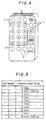
- a known infrared remote controller has a light transmitter 1 consisting of an infrared light transmitting element and an infrared transmission filter at its front end, and a number of operating keys 2 on its upper surface.
- Each of the operating keys 2 will then operate a corresponding function of an electrical appliance so that, for example, the key PW could turn the electric supply on and off, and the keys numbered [1] to [12] could then represent television channels.
- a signal is derived by modulating a fixed frequency carrier which is then transmitted as infrared radiation.
- the pulse bit periods, frame structures and coding systems of the signal depend on the format adopted, and in many cases these formats vary with the manufacturer, model or year in which the electrical appliance was made.
- the remote controller is exclusively designed in accordance with each electrical appliance, the user has to set up the remote controller so that it can be used with the electrical appliance for which it is intended.
- control signal groups for the electronic equipment corresponding to each of the manufacturers are prestored in, for example, a ROM.
- a manufacturer such as B Corporation then has two kinds of control signal groups having different formats and/or code systems (code CB1 and code CB2) these are then pre-stored separately.
- Each control signal group is then allotted to a numbered key and the user can then call up the desired control signal group by the select set up operation. For example, if key number [1] and the PW key are pressed together, the control signal group with the format and code system adopted by A Corporation will be selected, and when the operation keys 2 of the remote controller are subsequently pressed, the control signals for A Corporation's electronic equipment will be transmitted.
- a number of remote control signals which are stored in a memory are read out from the memory and transmitted one after another by operating one of the operating buttons so that it can then be decided which of these remote control signals is suitable to be used with the apparatus.
- a suitable remote control signal is selected, that selection is then stored in a memory.
- remote control signals corresponding to a number of formats, a number of manufacturers and a number of categories are pre-stored in the memory, by operating a prescribed operating key, the remote control signals stored in the memory can be read out and transmitted one after another from the memory, and a remote control signal which can be confirmed as being capable of operating the apparatus to be controlled can be found.
- each type of control signal group is preset into the unit. This means that, for example, by setting up appliance modes by using a select set up operation which employs the numbered keys, the number of control signal groups which can be preset is limited to the number of operating keys 2 (i.e. the number of numbered keys) present.
- control signal groups there are a very large number of kinds of control signal groups then, for example, if just twelve presets are assigned to certain control signal groups then there will still be groups which cannot be preset, and the remote controller will therefore not be able to operate the electronic equipment corresponding to these leftover groups.
- control signal group CA2 having the code system and format for A corporation will be selected.
- the user will not know which of three codes such as the three codes CB1 - CB3 shown in FIG. 3 for the products of C corporation should be selected, and so will therefore have to repeat the complicated select setting procedure until the correct control signal for operating that product has been output.
- the search preset function described previously can still be used as the remote control signal preset method.
- remote controllers which have a search preset function for the case where a remote control signal is to be read out from memory
- the remote control signals including the formats and control systems for the various makers may not correlate with those for conventional systems. It would therefore be best if the desired remote control signal were to be read out near the beginning of the sequence from which the remote control signals are read out from the memory, but this would probably not be the case. It would probably then be necessary to have to continue to press the operating button until the correct remote control signal is read out from the memory.
- a remote controller comprising a first storage means for storing a plurality of control signal groups corresponding to the various types of electronic equipment, a plurality of operating means for selecting the control signals for a control signal group to be selected from a plurality of control signal groups and a control means for making an output in accordance with all the various input operations.
- control signal groups within the storage means one or more of these control signal groups will be assigned to each one of the operating means, and when selecting one from a number of control signal groups assigned to a single operating means, each pressing of the operating means will bring up one particular control signal group.
- each of the control signal groups assigned to an operating means will be given a priority, with the lowest number of presses bringing forward the control signal group of the highest priority.
- a large number of types of control signal groups can be preset, as this storage operation is not limited to the number of operating means present.
- a user select setting operation can be made easy by having each operating means represent a particular maker and by then having each number of times that operating means is pressed represent each of that particular makers control signal groups with its differing formats and code systems. Again, this would be set up so that the most popular model by a particular maker would correspond to the lowest number of presses of the operating means.
- a preferred embodiment of the invention provides a remote controller which is capable of storing as presets a plurality of types of control signal groups in a manner which is not detrimental to the operativity of the select setting process for these control signal group presets.
- FIG. 2 is a block diagram of the remote controller according to this embodiment.
- the numeral 2 indicates operating keys as it does in FIG. 4, and there are numbered operating keys [1] - [12] for the preset control signal group select setting operations to be described later, as well as a PW key.
- Numeral 3 indicates a key matrix encoder for outputting the information input by the user via the operating keys 2.
- Numeral 4 indicates a microcomputer-based control unit which selects and outputs the desired control signal according to the operation input information provided by the key matrix encoder 3.
- Numeral 5 indicates an ROM (Read Only Memory). Various formats and code systems are adopted by different makers for their various models of electronic equipment and this ROM therefore contains preset data which cover this large number of control signal groups. The user can then select one control signal group from the data by using the select setting operation.
- the control signal for the control signal group selected is then put into an RAM (Random Access Memory) 9.
- RAM Random Access Memory
- the control signal for the control signal group selected is read from the RAM and then outputted.
- control signal for the control signal group selected is not put into the RAM 9 but can instead be stored in an address in the ROM 5. It is also preferable if the RAM 9 used for storing back up data is a non-volatile type RAM.
- numeral 6 indicates an LED (light emitting diode) driven infrared output section for outputting infrared light
- numeral 7 indicates an LED driver.
- the control section 4 uses the on/off switching function of an LED driver 7 driving transistor to turn the infrared output section 6 on and off, which in turn outputs the control signal via infrared light.
- Numeral 8 represents a sound generator which is controlled by the control section 4 to produce sounds such as electronically produced sounds.
- the control preset groups are stored in the ROM 5 as information for the keys numbered [1] - [12] as well as information concerning multiple presses of these keys.
- the keys numbered [1] - [12] could represent the corporations A to L and then each additional pressing operation will represent each of the various codes that corporation has adopted for its various electronic equipments.
- key number 1 could correspond to the control signal group which the corporation A uses for its products, with the two types of formats and code systems used by the corporation then being brought forward by pressing the key once for code CA1 and twice for code CA2.
- the type of code which is most commonly adopted by that corporation will correspond to the first pressing of the key, with the second most commonly adopted corresponding to the second pressing of the key, and so on.
- the select setting operation is enabled by, for example, pressing the PW (power) key and a numbered key at the same time.
- the control section 4 goes from normal control signal output mode into preset select setting mode (F100) and the variables K1, K0 and t are set, with K1 and t being set to zero (F101, F102).
- the variable K1 will hold the ID (Identification Code to classify the keys [1] - [12]) of the numbered key which had been most recently pressed during the period of the preset select setting mode.
- the variable K0 is the key number ID for the key currently being pressed and the variable t represents the number of times the same key has been continued to be pressed.
- the control section 4 recognizes when the PW key is no longer being pressed and at this point will embark upon the enter operation. If the PW key is released without a numbered key having been pressed while it was held down, i.e. the variables K1 and t are zero, there will not have been any new select setting operation and the system will return to normal mode. The control signal group selected in the previous select setting will then be outputted for any subsequent key operations (F103 ⁇ F112 ⁇ F115).
- the number of times the new key has been pressed is then determined in the following way.
- the next stage is to detect how many times the key has been pressed.
- the variable K1 0 (i.e. one press)
- the variable K1 is set to the ID of the currently inputted numbered key and the variable t is incremented.
- the step F109 then ensures that the variable t will display the number of times the same key has been pressed after subsequent pressings of the button.
- variable K1 is set to the value of the key number ID.
- the control signal group to be selected is then identified by using the information about the number of times the key has been pressed represented by the variable t to refer to the matrix shown in FIG. 3.
- the remote control signal is then set up in the RAM 9 so that the control output operations are carried out according to the control signal group selected (F113).
- a confirmation sound is then output from the sound generator 8 to confirm to the user that the control signal group select set up operation has been completed (F114) and the system returns to normal mode (F115).
- a numbered key is pressed more than the number of stored preset times, for example, in FIG. 3, if key number [1] is pressed three times or more, or key number [3] is pressed two times or more, the control signal group which is allotted to the highest number of allowed presses will be selected. It follows that if key number [1] is pressed three times or more then A corporations code CA2 will be selected and that if key number [3] is pressed a number of times then, as this key only has one kind of control signal group for its corresponding corporation, that signal group will be selected.
- the sound generator emit a warning noise when a key has been pressed the predetermined number of times.
- the select setting process involves designating control signal groups to the numbered keys and the multiple repetitive operations of the numbered keys. In this way, it is possible to store as presets a number of control signal groups which exceeds the number of actual numbered keys. A remote controller which is suitable for most of the models made by the majority of makers can therefore be attained. Having a numbered key for each corporation also means it is easy for the user to discriminate between the various makers and even if that maker has adopted a number of codes, it is possible to select the desired code in a simple manner by repeatedly pressing the corresponding key.
- control signal group with its format and control system preset within different positions in the matrix.
- a corporations code CA1 and J corporations code may be the same but they could still be recalled using different numbered keys so that the user does not get confused when carrying out the select set up operation.
- the select set up operation is not simply limited to the use of numbered keys as the operation keys. Also, the select set up process is not just limited to the process flow shown in FIG. 1.
- the operation keys in this embodiment correspond to corporations, but other variations are also possible.
- the operating keys could be made to correspond to various makers of electronic equipment such as televisions, video tape recorders (VTRs), and compact disc players, and the number of times the keys are pressed could then correspond to the various models produced by that particular maker.
- VTRs video tape recorders
- compact disc players the number of times the keys are pressed could then correspond to the various models produced by that particular maker.
Abstract
Description
- This invention relates to remote controllers such as those for remotely operating electronic equipment, and to methods of selectively setting remote control signals.
- Remote controllers are known which use infrared or other electromagnetic radiation to transmit modulated control data for remote control of electronic equipment such as televisions, stereos, and video tape recorders (VTRs).
- For example, as is shown in FIG. 4 of the accompanying drawings, a known infrared remote controller has a
light transmitter 1 consisting of an infrared light transmitting element and an infrared transmission filter at its front end, and a number ofoperating keys 2 on its upper surface. Each of theoperating keys 2 will then operate a corresponding function of an electrical appliance so that, for example, the key PW could turn the electric supply on and off, and the keys numbered [1] to [12] could then represent television channels. - Generally, a signal is derived by modulating a fixed frequency carrier which is then transmitted as infrared radiation. The pulse bit periods, frame structures and coding systems of the signal depend on the format adopted, and in many cases these formats vary with the manufacturer, model or year in which the electrical appliance was made. As the remote controller is exclusively designed in accordance with each electrical appliance, the user has to set up the remote controller so that it can be used with the electrical appliance for which it is intended.
- In response to this situation remote controllers have been proposed which can output control signals having different formats and code systems for various manufacturers and models of electronic equipment.
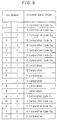
- With this kind of remote controller, as shown in the table of FIG. 5, the control signal groups for the electronic equipment corresponding to each of the manufacturers (A Corporation to I Corporation) are prestored in, for example, a ROM. When a manufacturer such as B Corporation then has two kinds of control signal groups having different formats and/or code systems (code CB1 and code CB2) these are then pre-stored separately.
- Each control signal group is then allotted to a numbered key and the user can then call up the desired control signal group by the select set up operation. For example, if key number [1] and the PW key are pressed together, the control signal group with the format and code system adopted by A Corporation will be selected, and when the
operation keys 2 of the remote controller are subsequently pressed, the control signals for A Corporation's electronic equipment will be transmitted. - A controller with the functions described above, commonly known as a preset remote controller, is disclosed in US Patent No. US-A-4 774 511.
- Also, in another kind of known remote controller, a number of remote control signals which are stored in a memory are read out from the memory and transmitted one after another by operating one of the operating buttons so that it can then be decided which of these remote control signals is suitable to be used with the apparatus. When a suitable remote control signal is selected, that selection is then stored in a memory.
- This kind of function, which is commonly known as a search preset function, is disclosed in, for example, US Patent No. US-A-4 703 359.
- In this way, if remote control signals corresponding to a number of formats, a number of manufacturers and a number of categories are pre-stored in the memory, by operating a prescribed operating key, the remote control signals stored in the memory can be read out and transmitted one after another from the memory, and a remote control signal which can be confirmed as being capable of operating the apparatus to be controlled can be found.
- With the preset remote controller described above, each type of control signal group is preset into the unit. This means that, for example, by setting up appliance modes by using a select set up operation which employs the numbered keys, the number of control signal groups which can be preset is limited to the number of operating keys 2 (i.e. the number of numbered keys) present.
- Also, if there are a very large number of kinds of control signal groups then, for example, if just twelve presets are assigned to certain control signal groups then there will still be groups which cannot be preset, and the remote controller will therefore not be able to operate the electronic equipment corresponding to these leftover groups.
- When presetting using numbered keys for a large number of types of control signal groups, it is possible to store the control signal groups by using two or more numbered keys corresponding to each control signal group, as shown in the example in FIG. 6. In this case, if, for example, the user holds down the key PW and then presses key [1] and key [2], the control signal group CA2 having the code system and format for A corporation will be selected.
- By doing this it will be possible to store almost any number of types of control signal formats and codes, although this will of course depend on the amount of memory space available in the ROM.
- This does however present the problem that the select setting operation is very complicated. Also, the user may understand the name of the maker of the electronic equipment being used but is unlikely to have an understanding that goes as far as knowing the control signal format and control system.
- Also, the user will not know which of three codes such as the three codes CB1 - CB3 shown in FIG. 3 for the products of C corporation should be selected, and so will therefore have to repeat the complicated select setting procedure until the correct control signal for operating that product has been output.
- If the user cannot manage to transmit the desired control signal format and code, then the search preset function described previously can still be used as the remote control signal preset method. However, with remote controllers which have a search preset function, for the case where a remote control signal is to be read out from memory, when the user operates the operating key the remote control signals including the formats and control systems for the various makers may not correlate with those for conventional systems. It would therefore be best if the desired remote control signal were to be read out near the beginning of the sequence from which the remote control signals are read out from the memory, but this would probably not be the case. It would probably then be necessary to have to continue to press the operating button until the correct remote control signal is read out from the memory.
- Storing a large number of types of control signal groups randomly as presets would therefore be detrimental to easy operation of the device.
- This application is a divisional from European patent application No. 93304281.4 filed on 2 June 1993, and published under No. 0 577 267.
- The invention is defined in the appended claims to which reference should now be made.
- According to one aspect of the invention, there is provided a remote controller comprising a first storage means for storing a plurality of control signal groups corresponding to the various types of electronic equipment, a plurality of operating means for selecting the control signals for a control signal group to be selected from a plurality of control signal groups and a control means for making an output in accordance with all the various input operations. By classifying which of the operating means has been pressed and working out how many times it has been pressed, the remote controllerwill designate one of a plurality of control signal groups in the select setting operation to the item, and will thus be able to operate various kinds of electronic equipment.
- More particularly, with regards to the plurality of control signal groups within the storage means, one or more of these control signal groups will be assigned to each one of the operating means, and when selecting one from a number of control signal groups assigned to a single operating means, each pressing of the operating means will bring up one particular control signal group.
- Also, each of the control signal groups assigned to an operating means will be given a priority, with the lowest number of presses bringing forward the control signal group of the highest priority.
- By designating a control signal group to a position in a matrix which corresponds to the number of times a particular operating means is pressed, a large number of types of control signal groups can be preset, as this storage operation is not limited to the number of operating means present. Also, a user select setting operation can be made easy by having each operating means represent a particular maker and by then having each number of times that operating means is pressed represent each of that particular makers control signal groups with its differing formats and code systems. Again, this would be set up so that the most popular model by a particular maker would correspond to the lowest number of presses of the operating means.
- Accordingly, a preferred embodiment of the invention provides a remote controller which is capable of storing as presets a plurality of types of control signal groups in a manner which is not detrimental to the operativity of the select setting process for these control signal group presets.
- The invention will now be described by way of example with reference to the accompanying drawings, throughout which like parts are referred to by like references, and in which:
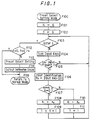
- FIG. 1 is a flowchart of the control signal group select setting process for an embodiment of the present invention;
- FIG. 2 is a block diagram of the construction of the remote controller in the embodiment;
- FIG. 3 is a diagram showing the way in which the control signal group presets are set out for the remote controller in the embodiment;
- FIG. 4 is a perspective view of the remote controller;
- FIG. 5 is a diagram showing the way in which the control signal group presets are set out for a previously-proposed remote controller; and
- FIG. 6 is a further view describing the way in which the control signal group presets are set out for another previously-proposed remote controller.
-
- The following is a description with reference to FIGS. 1-3 of an embodiment of the present invention. The external appearance of the remote controller is the same as that in FIG. 4.
- FIG. 2 is a block diagram of the remote controller according to this embodiment. Here, the
numeral 2 indicates operating keys as it does in FIG. 4, and there are numbered operating keys [1] - [12] for the preset control signal group select setting operations to be described later, as well as a PW key.Numeral 3 indicates a key matrix encoder for outputting the information input by the user via theoperating keys 2.Numeral 4 indicates a microcomputer-based control unit which selects and outputs the desired control signal according to the operation input information provided by thekey matrix encoder 3. Numeral 5 indicates an ROM (Read Only Memory). Various formats and code systems are adopted by different makers for their various models of electronic equipment and this ROM therefore contains preset data which cover this large number of control signal groups. The user can then select one control signal group from the data by using the select setting operation. - The control signal for the control signal group selected is then put into an RAM (Random Access Memory) 9. In the following, when an
operating key 2 is pressed, the control signal for the control signal group selected is read from the RAM and then outputted. - Also, in another embodiment, the control signal for the control signal group selected is not put into the
RAM 9 but can instead be stored in an address in theROM 5. It is also preferable if theRAM 9 used for storing back up data is a non-volatile type RAM. - In a
light emitter 1,numeral 6 indicates an LED (light emitting diode) driven infrared output section for outputting infrared light, andnumeral 7 indicates an LED driver. When thecontrol section 4 wishes to output a control signal (i.e. a signal which is a control signal which has been modulated by a fixed carrier), thecontrol section 4 uses the on/off switching function of anLED driver 7 driving transistor to turn theinfrared output section 6 on and off, which in turn outputs the control signal via infrared light. -
Numeral 8 represents a sound generator which is controlled by thecontrol section 4 to produce sounds such as electronically produced sounds. - The control preset groups are stored in the
ROM 5 as information for the keys numbered [1] - [12] as well as information concerning multiple presses of these keys. - For example, the keys numbered [1] - [12] could represent the corporations A to L and then each additional pressing operation will represent each of the various codes that corporation has adopted for its various electronic equipments. To illustrate this,
key number 1 could correspond to the control signal group which the corporation A uses for its products, with the two types of formats and code systems used by the corporation then being brought forward by pressing the key once for code CA1 and twice for code CA2.
For cases such as A corporation, B corporation and E corporation where two or more types of code are adopted, the type of code which is most commonly adopted by that corporation will correspond to the first pressing of the key, with the second most commonly adopted corresponding to the second pressing of the key, and so on. - This kind of select setting operation for the preset data i.e., the control signal group in the remote controller, will be described in conjunction with the flowchart in FIG. 1.
- The select setting operation is enabled by, for example, pressing the PW (power) key and a numbered key at the same time.
- When the PW key and a numbered key are pressed at the same time, the
control section 4 goes from normal control signal output mode into preset select setting mode (F100) and the variables K1, K0 and t are set, with K1 and t being set to zero (F101, F102). Here, the variable K1 will hold the ID (Identification Code to classify the keys [1] - [12]) of the numbered key which had been most recently pressed during the period of the preset select setting mode. The variable K0 is the key number ID for the key currently being pressed and the variable t represents the number of times the same key has been continued to be pressed. - In the preset select setting mode, the
control section 4 recognizes when the PW key is no longer being pressed and at this point will embark upon the enter operation. If the PW key is released without a numbered key having been pressed while it was held down, i.e. the variables K1 and t are zero, there will not have been any new select setting operation and the system will return to normal mode. The control signal group selected in the previous select setting will then be outputted for any subsequent key operations (F103 → F112 → F115). - While the PW key is being held down, a loop scan of the input keys is taking place to see if any keys have been pressed (F103, F104, F105). If there is an input corresponding to the operation of one of the numbered keys, it is first determined which of the keys [1] - [12] has been pressed, and the constant K0 is set to this key ID (F106). Also, if K1 = K0, K1 = 0, a certain key corresponding to a certain maker is pressed once or a number of times, or a numbered key other than the numbered key which had been most recently pressed during the previous period of the preset select setting mode is pressed, a confirmation will be outputted. Cases such as the user pressing the wrong key and then pressing the correct key after having pressed the wrong key must also be taken into account.
- In this kind of case, the ID variable K1 for the numbered key pressed just beforehand is replaced with the ID for the key most currently pressed (F110) , and the variable t is set to t = 1 (F111). The number of times the new key has been pressed is then determined in the following way. When the process continues through steps F107 and F108, the next stage is to detect how many times the key has been pressed. When the variable K1 = 0 (i.e. one press), the variable K1 is set to the ID of the currently inputted numbered key and the variable t is incremented. The step F109 then ensures that the variable t will display the number of times the same key has been pressed after subsequent pressings of the button.
- When the PW key is no longer being pressed, the enter operation is embarked upon and at the same time the variable K1 is set to the value of the key number ID. The control signal group to be selected is then identified by using the information about the number of times the key has been pressed represented by the variable t to refer to the matrix shown in FIG. 3. The remote control signal is then set up in the
RAM 9 so that the control output operations are carried out according to the control signal group selected (F113). A confirmation sound is then output from thesound generator 8 to confirm to the user that the control signal group select set up operation has been completed (F114) and the system returns to normal mode (F115). - In case where a numbered key is pressed more than the number of stored preset times, for example, in FIG. 3, if key number [1] is pressed three times or more, or key number [3] is pressed two times or more, the control signal group which is allotted to the highest number of allowed presses will be selected. It follows that if key number [1] is pressed three times or more then A corporations code CA2 will be selected and that if key number [3] is pressed a number of times then, as this key only has one kind of control signal group for its corresponding corporation, that signal group will be selected.
- In this way, when the keys are pressed more than the number of times for which there are presets the user will not become confused because this system does not, for example, return to normal operating conditions after just one press of the keys. For example, as the user realizes that there is only a few preset control signal groups for this particular maker it should become understood that this is not, in fact, a particularly complicated process. If, at this stage, taking corporation B as an example, pressing key number [2] five times brings up B Corporations code CB1 and pressing it six times brings up B Corporations code CB2 so that the codes are then sequentially repeated, it is easy for the user to no longer be aware of which code is being dealt with. Also, having to press the wrong key a number of times and then having to reset again could make the user feel apprehensive about the set up process. It is therefore preferable to have the sound generator emit a warning noise when a key has been pressed the predetermined number of times.
- In the remote controller according to this embodiment, the select setting process involves designating control signal groups to the numbered keys and the multiple repetitive operations of the numbered keys. In this way, it is possible to store as presets a number of control signal groups which exceeds the number of actual numbered keys. A remote controller which is suitable for most of the models made by the majority of makers can therefore be attained. Having a numbered key for each corporation also means it is easy for the user to discriminate between the various makers and even if that maker has adopted a number of codes, it is possible to select the desired code in a simple manner by repeatedly pressing the corresponding key.
- Also, as the codes which are used the most correspond to the lower numbers of operations of the keys, it is simple to use for a very large number of users.
- It is also possible to have the same kind of control signal group with its format and control system preset within different positions in the matrix. For example, A corporations code CA1 and J corporations code may be the same but they could still be recalled using different numbered keys so that the user does not get confused when carrying out the select set up operation.
- The select set up operation is not simply limited to the use of numbered keys as the operation keys. Also, the select set up process is not just limited to the process flow shown in FIG. 1.
- Further, the operation keys in this embodiment correspond to corporations, but other variations are also possible. For example, the operating keys could be made to correspond to various makers of electronic equipment such as televisions, video tape recorders (VTRs), and compact disc players, and the number of times the keys are pressed could then correspond to the various models produced by that particular maker.
Claims (13)
- A method of selectively setting groups of remote control signals, comprising the steps of:(a) designating (F100) a preset select setting mode;(b) discriminating (F103, F104, F105) whether or not there is an input issued from an operating means;(c) storing (F106) an identification code (K0) according to said input from the operating means;(d) discriminating (F107) whether or not said identification code (K0) coincides with a predesignated identification code (K1), or whether the operating means has been pressed one or more times; and if the presently designated identification code (K0) coincides with the predesignated identification code (K1), changing said predesignated identification code (K1) to the presently designated identification code and increasing (F111) by one a stored count (t) of the number of times the same operating means has been actuated; and(e) discriminating (F113), according to said input from the operating means, the remote control signal group selected according to said identification code and according to the number of times the operating means has been pressed, and storing in a first storage means (9) remote control signals data corresponding to the remote control signal group selected.
- The method according to claim 1, wherein said identification codes are assigned for the respective manufacturers of different equipment to be controlled.
- The method according to claim 1, wherein said identification codes are assigned for the respective categories of different equipments to be controlled.
- The method according to claim 1, wherein said identification codes are assigned for the respective remote control format systems of different equipments to be controlled.
- A method according to any preceding claim, further comprising the step of reading remote control signal data corresponding to the selected remote control signal group from a second memory means (5).
- A method according to any preceding claim further comprising the step of setting to '1' a stored count (t) of the number of times the present identification code has been input from the operating means, when the presently designated identification code (K0) does not coincide with the predesignated identification code (K1), and when the predesignated identification code does not have a predetermined value.
- A method according to any preceding claim further comprising the step of outputting (F114) an audible signal to indicate that a remote control signal group has been selected.
- A method according to any preceding claim, in which if successive inputs issue from the same operating means a number of times larger than the number of remote control signal groups assigned to that operating means, the remote control signal group corresponding to the highest number of actuations of that operating means is selected.
- A method according to any preceding claim further comprising the step of issuing a warning signal when the number of times an operating means is pressed is larger than the number of remote control signal groups assigned thereto.
- A method according to claim 9, in which said warning signal is a warning sound or display.
- A method according to any preceding claim in which remote control signal groups are assigned to a number of activations of an operating means according to a predetermined order of priority.
- A method according to claim 11 in which the priority order relates to a market share of the manufacturer of equipment to be controlled.
- A method according to claim 11 in which the priority order is in accordance with the degree of use of the format of the remote control signal groups.
Applications Claiming Priority (3)
| Application Number | Priority Date | Filing Date | Title |
|---|---|---|---|
| JP18284692 | 1992-06-18 | ||
| JP18284692A JP3214073B2 (en) | 1992-06-18 | 1992-06-18 | Remote commander and remote commander setting method |
| EP93304281A EP0577267A1 (en) | 1992-06-18 | 1993-06-02 | Remote controllers and methods of selectively setting remote control signals |
Related Parent Applications (1)
| Application Number | Title | Priority Date | Filing Date |
|---|---|---|---|
| EP93304281A Division EP0577267A1 (en) | 1992-06-18 | 1993-06-02 | Remote controllers and methods of selectively setting remote control signals |
Publications (3)
| Publication Number | Publication Date |
|---|---|
| EP0984560A2 true EP0984560A2 (en) | 2000-03-08 |
| EP0984560A3 EP0984560A3 (en) | 2000-05-03 |
| EP0984560B1 EP0984560B1 (en) | 2001-12-12 |
Family
ID=16125486
Family Applications (2)
| Application Number | Title | Priority Date | Filing Date |
|---|---|---|---|
| EP93304281A Ceased EP0577267A1 (en) | 1992-06-18 | 1993-06-02 | Remote controllers and methods of selectively setting remote control signals |
| EP99121044A Expired - Lifetime EP0984560B1 (en) | 1992-06-18 | 1993-06-02 | Remote controllers and methods of selectively setting remote control signals |
Family Applications Before (1)
| Application Number | Title | Priority Date | Filing Date |
|---|---|---|---|
| EP93304281A Ceased EP0577267A1 (en) | 1992-06-18 | 1993-06-02 | Remote controllers and methods of selectively setting remote control signals |
Country Status (5)
| Country | Link |
|---|---|
| US (1) | US5485149A (en) |
| EP (2) | EP0577267A1 (en) |
| JP (1) | JP3214073B2 (en) |
| CA (1) | CA2097411C (en) |
| DE (1) | DE69331352T2 (en) |
Families Citing this family (23)
| Publication number | Priority date | Publication date | Assignee | Title |
|---|---|---|---|---|
| JPH077771A (en) * | 1993-03-19 | 1995-01-10 | Sony Corp | Remote commander |
| JPH0799690A (en) * | 1993-09-28 | 1995-04-11 | Sony Corp | Remote commander |
| US5969774A (en) * | 1994-11-17 | 1999-10-19 | Wininger; Dixon | Programmable remote control transmitter |
| AU1972297A (en) * | 1996-03-01 | 1997-09-16 | U.S. Electronics Components Corp. | Programmable universal remote control |
| US5614906A (en) * | 1996-04-23 | 1997-03-25 | Universal Electronics Inc. | Method for selecting a remote control command set |
| JP3783282B2 (en) * | 1996-06-04 | 2006-06-07 | ソニー株式会社 | COMMUNICATION CONTROL METHOD, COMMUNICATION SYSTEM AND ELECTRONIC DEVICE USED FOR THE SAME |
| US5819294A (en) * | 1997-08-06 | 1998-10-06 | Philips Electronics North America Corporation | Automatic configuration mechanism for universal remote |
| FR2768890B1 (en) * | 1997-09-19 | 1999-12-03 | Charles Moransais | ADAPTABLE REMOTE CONTROL FOR ELECTRICAL APPLIANCES WITH MULTIPLE FUNCTIONS TO ORDER |
| US5910784A (en) * | 1997-10-06 | 1999-06-08 | Lai; Jung-Hua | Control circuit of a remote controller |
| US6101401A (en) * | 1998-08-26 | 2000-08-08 | Dbtel Incorporated | Wireless telephone dialing method |
| US6282152B1 (en) | 1999-03-09 | 2001-08-28 | Timex Corporation | Learning security control device |
| KR100396547B1 (en) * | 2000-12-27 | 2003-09-02 | 삼성전자주식회사 | Method for generating and receiving/transmitting input code in universal input-device and apparatus thereof |
| JP5008463B2 (en) * | 2007-06-05 | 2012-08-22 | スタンレー電気株式会社 | Dimming method and lighting device employing the dimming method |
| US8130079B2 (en) * | 2007-08-15 | 2012-03-06 | At&T Intellectual Property I, L.P. | Methods, systems, and products for discovering electronic devices |
| JP4946986B2 (en) * | 2008-06-30 | 2012-06-06 | 株式会社Jvcケンウッド | Remote control device and preset method of remote control device |
| KR101603340B1 (en) * | 2009-07-24 | 2016-03-14 | 엘지전자 주식회사 | Controller and an operating method thereof |
| JP2012070035A (en) * | 2010-09-21 | 2012-04-05 | Giga-Byte Technology Co Ltd | Keyboard having macro function, method for setting macro function related thereto and computer program product therefor |
| US9542834B2 (en) * | 2011-01-28 | 2017-01-10 | Gentex Corporation | Wireless trainable transceiver device with integrated interface and GPS modules |
| US20120317104A1 (en) * | 2011-06-13 | 2012-12-13 | Microsoft Corporation | Using Aggregate Location Metadata to Provide a Personalized Service |
| US8949053B2 (en) | 2011-07-29 | 2015-02-03 | Schneider Electric It Corporation | Systems and methods for current and voltage monitoring |
| US9210376B2 (en) | 2013-03-15 | 2015-12-08 | Infocus Corporation | Multimedia output and display device selection |
| US10372397B2 (en) | 2013-03-15 | 2019-08-06 | Infocus Corporation | Multimedia output and display device selection |
| JP6073735B2 (en) * | 2013-04-12 | 2017-02-01 | 株式会社小糸製作所 | Vehicle lamp |
Citations (4)
| Publication number | Priority date | Publication date | Assignee | Title |
|---|---|---|---|---|
| EP0122548A2 (en) * | 1983-04-14 | 1984-10-24 | TELEFUNKEN Fernseh und Rundfunk GmbH | Remote control apparatus for the wireless control of various devices |
| US4703359A (en) * | 1985-05-30 | 1987-10-27 | Nap Consumer Electronics Corp. | Universal remote control unit with model identification capability |
| US4843386A (en) * | 1986-05-12 | 1989-06-27 | Siemens Aktiengesellschaft | Remote control unit with hierarchical selection |
| EP0331257A2 (en) * | 1988-03-04 | 1989-09-06 | Philips Electronics North America Corporation | Universal remote control transmitter with simplified device indentification |
Family Cites Families (6)
| Publication number | Priority date | Publication date | Assignee | Title |
|---|---|---|---|---|
| DE122548C (en) * | ||||
| US4774511A (en) * | 1985-05-30 | 1988-09-27 | Nap Consumer Electronics Corp. | Universal remote control unit |
| US4694725A (en) * | 1985-09-03 | 1987-09-22 | Ncr Corporation | Sound generating system for a keyboard |
| JPH01117595A (en) * | 1987-10-30 | 1989-05-10 | Nec Home Electron Ltd | Transmitter for remote controller |
| JP2687454B2 (en) * | 1988-06-28 | 1997-12-08 | ソニー株式会社 | General commander |
| US4866434A (en) * | 1988-12-22 | 1989-09-12 | Thomson Consumer Electronics, Inc. | Multi-brand universal remote control |
-
1992
- 1992-06-18 JP JP18284692A patent/JP3214073B2/en not_active Expired - Fee Related
-
1993
- 1993-05-31 CA CA002097411A patent/CA2097411C/en not_active Expired - Fee Related
- 1993-06-02 DE DE69331352T patent/DE69331352T2/en not_active Expired - Fee Related
- 1993-06-02 EP EP93304281A patent/EP0577267A1/en not_active Ceased
- 1993-06-02 EP EP99121044A patent/EP0984560B1/en not_active Expired - Lifetime
- 1993-06-09 US US08/074,092 patent/US5485149A/en not_active Expired - Lifetime
Patent Citations (4)
| Publication number | Priority date | Publication date | Assignee | Title |
|---|---|---|---|---|
| EP0122548A2 (en) * | 1983-04-14 | 1984-10-24 | TELEFUNKEN Fernseh und Rundfunk GmbH | Remote control apparatus for the wireless control of various devices |
| US4703359A (en) * | 1985-05-30 | 1987-10-27 | Nap Consumer Electronics Corp. | Universal remote control unit with model identification capability |
| US4843386A (en) * | 1986-05-12 | 1989-06-27 | Siemens Aktiengesellschaft | Remote control unit with hierarchical selection |
| EP0331257A2 (en) * | 1988-03-04 | 1989-09-06 | Philips Electronics North America Corporation | Universal remote control transmitter with simplified device indentification |
Also Published As
| Publication number | Publication date |
|---|---|
| DE69331352D1 (en) | 2002-01-24 |
| US5485149A (en) | 1996-01-16 |
| EP0984560A3 (en) | 2000-05-03 |
| JPH066876A (en) | 1994-01-14 |
| EP0577267A1 (en) | 1994-01-05 |
| EP0984560B1 (en) | 2001-12-12 |
| JP3214073B2 (en) | 2001-10-02 |
| CA2097411C (en) | 2003-04-22 |
| DE69331352T2 (en) | 2002-08-22 |
| CA2097411A1 (en) | 1993-12-19 |
Similar Documents
| Publication | Publication Date | Title |
|---|---|---|
| EP0984560B1 (en) | Remote controllers and methods of selectively setting remote control signals | |
| KR100323967B1 (en) | Remote commander to select and set preset data | |
| AU592991B2 (en) | Universal remote control unit | |
| US6236350B1 (en) | Universal remote control code identification system | |
| US5341166A (en) | System for controlling selected devices having unique sets of control codes | |
| US5255313A (en) | Universal remote control system | |
| US4999622A (en) | Remote commander having a ROM read-out pre-programmed codes therefrom | |
| US5386251A (en) | Television receiver with learning remote control system capable of being controlled by a remote control device manufactured by different companies | |
| US6344817B1 (en) | Method of displaying manufacturer/model code and programmable universal remote control employing same | |
| US7116264B2 (en) | Programmable universal remote control unit | |
| US6947101B2 (en) | Control device with easy lock feature | |
| US5414426A (en) | Favorite key macro command and chained macro command in a remote control | |
| EP0176965B1 (en) | Remote control apparatus | |
| US5872562A (en) | Universal remote control transmitter with simplified device identification | |
| US20030053002A1 (en) | Universal remote control unit | |
| US7154566B2 (en) | Programmable universal remote control unit and method of programming same | |
| US6078270A (en) | Data transmission method of a remote controller | |
| EP1112655B2 (en) | Method for storage of a channel for a consumer electronics appliance | |
| EP0331257B1 (en) | Universal remote control transmitter with simplified device indentification | |
| CN100416619C (en) | Method for controlling several apparatuses with the aid of a link attached device and said link attached device for carrying out said method | |
| KR100491701B1 (en) | Remote control apparatus and method for programming said apparatus | |
| KR100839888B1 (en) | Unit and method for remote control | |
| JP3052101U (en) | Remote controller for electric appliances | |
| EP0660538A2 (en) | Remote control system | |
| WO1992003022A1 (en) | Universal remote control including quick touch function |
Legal Events
| Date | Code | Title | Description |
|---|---|---|---|
| PUAI | Public reference made under article 153(3) epc to a published international application that has entered the european phase |
Free format text: ORIGINAL CODE: 0009012 |
|
| AC | Divisional application: reference to earlier application |
Ref document number: 577267 Country of ref document: EP |
|
| AK | Designated contracting states |
Kind code of ref document: A2 Designated state(s): DE FR GB |
|
| PUAL | Search report despatched |
Free format text: ORIGINAL CODE: 0009013 |
|
| AK | Designated contracting states |
Kind code of ref document: A3 Designated state(s): DE FR GB |
|
| 17P | Request for examination filed |
Effective date: 20000929 |
|
| AKX | Designation fees paid |
Free format text: DE FR GB |
|
| GRAG | Despatch of communication of intention to grant |
Free format text: ORIGINAL CODE: EPIDOS AGRA |
|
| 17Q | First examination report despatched |
Effective date: 20010404 |
|
| GRAG | Despatch of communication of intention to grant |
Free format text: ORIGINAL CODE: EPIDOS AGRA |
|
| GRAH | Despatch of communication of intention to grant a patent |
Free format text: ORIGINAL CODE: EPIDOS IGRA |
|
| GRAH | Despatch of communication of intention to grant a patent |
Free format text: ORIGINAL CODE: EPIDOS IGRA |
|
| GRAA | (expected) grant |
Free format text: ORIGINAL CODE: 0009210 |
|
| AC | Divisional application: reference to earlier application |
Ref document number: 577267 Country of ref document: EP |
|
| AK | Designated contracting states |
Kind code of ref document: B1 Designated state(s): DE FR GB |
|
| REG | Reference to a national code |
Ref country code: GB Ref legal event code: IF02 |
|
| REF | Corresponds to: |
Ref document number: 69331352 Country of ref document: DE Date of ref document: 20020124 |
|
| ET | Fr: translation filed | ||
| PLBE | No opposition filed within time limit |
Free format text: ORIGINAL CODE: 0009261 |
|
| STAA | Information on the status of an ep patent application or granted ep patent |
Free format text: STATUS: NO OPPOSITION FILED WITHIN TIME LIMIT |
|
| 26N | No opposition filed | ||
| PGFP | Annual fee paid to national office [announced via postgrant information from national office to epo] |
Ref country code: GB Payment date: 20030528 Year of fee payment: 11 |
|
| PGFP | Annual fee paid to national office [announced via postgrant information from national office to epo] |
Ref country code: FR Payment date: 20030610 Year of fee payment: 11 |
|
| PGFP | Annual fee paid to national office [announced via postgrant information from national office to epo] |
Ref country code: DE Payment date: 20030612 Year of fee payment: 11 |
|
| PG25 | Lapsed in a contracting state [announced via postgrant information from national office to epo] |
Ref country code: GB Free format text: LAPSE BECAUSE OF NON-PAYMENT OF DUE FEES Effective date: 20040602 |
|
| PG25 | Lapsed in a contracting state [announced via postgrant information from national office to epo] |
Ref country code: DE Free format text: LAPSE BECAUSE OF NON-PAYMENT OF DUE FEES Effective date: 20050101 |
|
| GBPC | Gb: european patent ceased through non-payment of renewal fee | ||
| PG25 | Lapsed in a contracting state [announced via postgrant information from national office to epo] |
Ref country code: FR Free format text: LAPSE BECAUSE OF NON-PAYMENT OF DUE FEES Effective date: 20050228 |
|
| REG | Reference to a national code |
Ref country code: FR Ref legal event code: ST |