EP0985491A2 - Method and apparatus for machining a workpiece by piercing - Google Patents
Method and apparatus for machining a workpiece by piercing Download PDFInfo
- Publication number
- EP0985491A2 EP0985491A2 EP99306818A EP99306818A EP0985491A2 EP 0985491 A2 EP0985491 A2 EP 0985491A2 EP 99306818 A EP99306818 A EP 99306818A EP 99306818 A EP99306818 A EP 99306818A EP 0985491 A2 EP0985491 A2 EP 0985491A2
- Authority
- EP
- European Patent Office
- Prior art keywords
- pressure
- workpiece
- nozzle assembly
- shield
- shield means
- Prior art date
- Legal status (The legal status is an assumption and is not a legal conclusion. Google has not performed a legal analysis and makes no representation as to the accuracy of the status listed.)
- Withdrawn
Links
Images

Classifications
-
- G—PHYSICS
- G05—CONTROLLING; REGULATING
- G05B—CONTROL OR REGULATING SYSTEMS IN GENERAL; FUNCTIONAL ELEMENTS OF SUCH SYSTEMS; MONITORING OR TESTING ARRANGEMENTS FOR SUCH SYSTEMS OR ELEMENTS
- G05B19/00—Programme-control systems
- G05B19/02—Programme-control systems electric
- G05B19/18—Numerical control [NC], i.e. automatically operating machines, in particular machine tools, e.g. in a manufacturing environment, so as to execute positioning, movement or co-ordinated operations by means of programme data in numerical form
- G05B19/182—Numerical control [NC], i.e. automatically operating machines, in particular machine tools, e.g. in a manufacturing environment, so as to execute positioning, movement or co-ordinated operations by means of programme data in numerical form characterised by the machine tool function, e.g. thread cutting, cam making, tool direction control
-
- B—PERFORMING OPERATIONS; TRANSPORTING
- B23—MACHINE TOOLS; METAL-WORKING NOT OTHERWISE PROVIDED FOR
- B23K—SOLDERING OR UNSOLDERING; WELDING; CLADDING OR PLATING BY SOLDERING OR WELDING; CUTTING BY APPLYING HEAT LOCALLY, e.g. FLAME CUTTING; WORKING BY LASER BEAM
- B23K10/00—Welding or cutting by means of a plasma
- B23K10/006—Control circuits therefor
-
- B—PERFORMING OPERATIONS; TRANSPORTING
- B23—MACHINE TOOLS; METAL-WORKING NOT OTHERWISE PROVIDED FOR
- B23K—SOLDERING OR UNSOLDERING; WELDING; CLADDING OR PLATING BY SOLDERING OR WELDING; CUTTING BY APPLYING HEAT LOCALLY, e.g. FLAME CUTTING; WORKING BY LASER BEAM
- B23K26/00—Working by laser beam, e.g. welding, cutting or boring
- B23K26/02—Positioning or observing the workpiece, e.g. with respect to the point of impact; Aligning, aiming or focusing the laser beam
- B23K26/03—Observing, e.g. monitoring, the workpiece
-
- B—PERFORMING OPERATIONS; TRANSPORTING
- B23—MACHINE TOOLS; METAL-WORKING NOT OTHERWISE PROVIDED FOR
- B23K—SOLDERING OR UNSOLDERING; WELDING; CLADDING OR PLATING BY SOLDERING OR WELDING; CUTTING BY APPLYING HEAT LOCALLY, e.g. FLAME CUTTING; WORKING BY LASER BEAM
- B23K26/00—Working by laser beam, e.g. welding, cutting or boring
- B23K26/14—Working by laser beam, e.g. welding, cutting or boring using a fluid stream, e.g. a jet of gas, in conjunction with the laser beam; Nozzles therefor
-
- B—PERFORMING OPERATIONS; TRANSPORTING
- B23—MACHINE TOOLS; METAL-WORKING NOT OTHERWISE PROVIDED FOR
- B23K—SOLDERING OR UNSOLDERING; WELDING; CLADDING OR PLATING BY SOLDERING OR WELDING; CUTTING BY APPLYING HEAT LOCALLY, e.g. FLAME CUTTING; WORKING BY LASER BEAM
- B23K26/00—Working by laser beam, e.g. welding, cutting or boring
- B23K26/36—Removing material
- B23K26/38—Removing material by boring or cutting
- B23K26/382—Removing material by boring or cutting by boring
-
- B—PERFORMING OPERATIONS; TRANSPORTING
- B23—MACHINE TOOLS; METAL-WORKING NOT OTHERWISE PROVIDED FOR
- B23K—SOLDERING OR UNSOLDERING; WELDING; CLADDING OR PLATING BY SOLDERING OR WELDING; CUTTING BY APPLYING HEAT LOCALLY, e.g. FLAME CUTTING; WORKING BY LASER BEAM
- B23K7/00—Cutting, scarfing, or desurfacing by applying flames
- B23K7/10—Auxiliary devices, e.g. for guiding or supporting the torch
-
- B—PERFORMING OPERATIONS; TRANSPORTING
- B24—GRINDING; POLISHING
- B24C—ABRASIVE OR RELATED BLASTING WITH PARTICULATE MATERIAL
- B24C1/00—Methods for use of abrasive blasting for producing particular effects; Use of auxiliary equipment in connection with such methods
- B24C1/04—Methods for use of abrasive blasting for producing particular effects; Use of auxiliary equipment in connection with such methods for treating only selected parts of a surface, e.g. for carving stone or glass
- B24C1/045—Methods for use of abrasive blasting for producing particular effects; Use of auxiliary equipment in connection with such methods for treating only selected parts of a surface, e.g. for carving stone or glass for cutting
-
- B—PERFORMING OPERATIONS; TRANSPORTING
- B24—GRINDING; POLISHING
- B24C—ABRASIVE OR RELATED BLASTING WITH PARTICULATE MATERIAL
- B24C7/00—Equipment for feeding abrasive material; Controlling the flowability, constitution, or other physical characteristics of abrasive blasts
- B24C7/0046—Equipment for feeding abrasive material; Controlling the flowability, constitution, or other physical characteristics of abrasive blasts the abrasive material being fed in a gaseous carrier
- B24C7/0053—Equipment for feeding abrasive material; Controlling the flowability, constitution, or other physical characteristics of abrasive blasts the abrasive material being fed in a gaseous carrier with control of feed parameters, e.g. feed rate of abrasive material or carrier
-
- B—PERFORMING OPERATIONS; TRANSPORTING
- B24—GRINDING; POLISHING
- B24C—ABRASIVE OR RELATED BLASTING WITH PARTICULATE MATERIAL
- B24C7/00—Equipment for feeding abrasive material; Controlling the flowability, constitution, or other physical characteristics of abrasive blasts
- B24C7/0046—Equipment for feeding abrasive material; Controlling the flowability, constitution, or other physical characteristics of abrasive blasts the abrasive material being fed in a gaseous carrier
- B24C7/0076—Equipment for feeding abrasive material; Controlling the flowability, constitution, or other physical characteristics of abrasive blasts the abrasive material being fed in a gaseous carrier the blasting medium being a liquid stream
-
- B—PERFORMING OPERATIONS; TRANSPORTING
- B26—HAND CUTTING TOOLS; CUTTING; SEVERING
- B26D—CUTTING; DETAILS COMMON TO MACHINES FOR PERFORATING, PUNCHING, CUTTING-OUT, STAMPING-OUT OR SEVERING
- B26D5/00—Arrangements for operating and controlling machines or devices for cutting, cutting-out, stamping-out, punching, perforating, or severing by means other than cutting
- B26D5/005—Computer numerical control means
-
- B—PERFORMING OPERATIONS; TRANSPORTING
- B26—HAND CUTTING TOOLS; CUTTING; SEVERING
- B26F—PERFORATING; PUNCHING; CUTTING-OUT; STAMPING-OUT; SEVERING BY MEANS OTHER THAN CUTTING
- B26F3/00—Severing by means other than cutting; Apparatus therefor
- B26F3/004—Severing by means other than cutting; Apparatus therefor by means of a fluid jet
-
- G—PHYSICS
- G05—CONTROLLING; REGULATING
- G05B—CONTROL OR REGULATING SYSTEMS IN GENERAL; FUNCTIONAL ELEMENTS OF SUCH SYSTEMS; MONITORING OR TESTING ARRANGEMENTS FOR SUCH SYSTEMS OR ELEMENTS
- G05B2219/00—Program-control systems
- G05B2219/30—Nc systems
- G05B2219/37—Measurements
- G05B2219/37409—Measure different pressure of fluid flow on contacting surface
-
- G—PHYSICS
- G05—CONTROLLING; REGULATING
- G05B—CONTROL OR REGULATING SYSTEMS IN GENERAL; FUNCTIONAL ELEMENTS OF SUCH SYSTEMS; MONITORING OR TESTING ARRANGEMENTS FOR SUCH SYSTEMS OR ELEMENTS
- G05B2219/00—Program-control systems
- G05B2219/30—Nc systems
- G05B2219/37—Measurements
- G05B2219/37583—Detect separation, cutting, penetration, piercing, break through material
-
- G—PHYSICS
- G05—CONTROLLING; REGULATING
- G05B—CONTROL OR REGULATING SYSTEMS IN GENERAL; FUNCTIONAL ELEMENTS OF SUCH SYSTEMS; MONITORING OR TESTING ARRANGEMENTS FOR SUCH SYSTEMS OR ELEMENTS
- G05B2219/00—Program-control systems
- G05B2219/30—Nc systems
- G05B2219/40—Robotics, robotics mapping to robotics vision
- G05B2219/40064—Pierce, penetrate soft tissue
Definitions
- This invention relates generally to sensing methods and apparatus and more particularly to methods and apparatus for monitoring abrasive waterjet machining of engineering materials.
- Abrasive water jet (AWJ) processes employ materials entrained into a high-pressure waterjet to perform a variety of cutting and other machinery operations on a variety of materials.
- the high-energy waterjet beam utilised combines a rapid erosion of a workpiece material by high speed solid particle impacts with rapid cooling provided by a waterjet.
- AWJ cutting operations an abrasive waterjet pierces through the thickness of and is then moved along a material to be cut.
- various physical dimensions such as workpiece thickness must be measured in order to properly configure the water pressure, abrasive flow rate and other system parameters for the AWJ apparatus.
- the proximity of and distances between various components of the AWJ apparatus and the workpiece must be monitored. For example, the proximity of an AWJ nozzle to a workpiece must be monitored with respect to establishing and maintaining air gap and stand-off distances within acceptable tolerance ranges.
- physical events such as the moment of pierce-through of a workpiece by an AWJ waterjet during a cutting operation must also be detected in order to establish when the relative motion between the workpiece and an AWJ nozzle should be commenced.
- an apparatus for sensing a pierce-through condition of a material made by a piercing force comprising a shield means for surrounding a source of said piercing force, a means for supplying a gas to create a pressure within said shield means, and a sensing means for detecting a decrease in pressure caused within said shield means by said pierce-through condition created by said piercing force.
- an apparatus for detecting the distance between a nozzle assembly for a machining process and a workpiece to be machined comprising a shield means for surrounding a nozzle assembly, said shield means being open at one end to permit a piercing force from said nozzle assembly to exit said shield means, a means for supplying a gas to create a pressure within said shield means, and a sensing means for detecting an increase in pressure caused within said shield means as said open end of said shield means approaches the workpiece to be machined.
- a method of sensing a pierce-through condition of a material made by a piercing force comprising the steps of supplying a gas to create a pressure within a shield means surrounding a source of a piercing force, and detecting a decrease in pressure caused within said shield means by said pierce-through condition created by said piercing force.
- a method of detecting the distance between a nozzle assembly for a machining process and a workpiece to be machined comprising supplying a gas to create a pressure within a shield means surrounding a nozzle assembly, said shield means being open at one end to permit a piercing force from said nozzle assembly to exit said shield means, and detecting an increase in pressure caused within said shield means as said open end of said shield means approaches a workpiece to be machined.
- Fig. 1 shows a broad system diagram of an embodiment as applied to an abrasive waterjet (AWJ) system.
- a nozzle assembly 10 comprising an orifice 12 and a focussing tube 14 which applies a mixture of high pressure water and abrasive to a moving workpiece 16.
- the nozzle assembly 10 is preferably supplied with abrasive from an optional vibration feeder 20 and high pressure water from a water source 22. Although shown using a vibration feeder, other types of feeding devices may be used for this purpose.
- a controlling unit 30 is typically provided for receiving input on the operating conditions of the AWJ system and controlling the motion of the nozzle assembly 10 and workpiece 16.
- the controlling unit 30 is preferably a Computerised Numerical Controller (CNC) which is available and may include, e.g. a Model ACR 2000 motion controller from Acroloop Motion Control Systems, Inc., Chanhassen, MN, U.S.A.
- CNC Computerised Numerical Controller
- the controlling unit 30 Prior to performing an AWJ cutting or other machining operation, the controlling unit 30 is preset by a user with AWJ system operating parameters such as water pressure, abrasive particle size, abrasive flow rate and the dimensions of the waterjet nozzle orifice. These parameters are varied depending on the type of workpiece material and the type of machining operation to be performed.
- the controlling unit 30 controls the feed from the vibration feeder 20 and the feed supply of high pressure water from the water source 22.
- the workpiece 16 is moved back and forth by positioning equipment (not shown) which manoeuvres the workpiece at the proper traverse speed for the desired cutting or other machining operation.
- the positioning equipment is responsive to and controlled by a control signal 26 provided by the controlling unit 30, which may also be used to calculate the traverse speed.
- the multi-functional sensing apparatus which comprises a nozzle shield 15 surrounding the focussing tube 14.
- the nozzle shield 15 is connected to and in fluid communication with an air or other gas supply 40 via a conduit 41.
- a pressure sensor 42 is connected to the conduit 41 and located between the nozzle shield 15 and air supply 40 for sensing the pressure conditions inside the nozzle shield 15 and providing a pressure sensor signal 43 to the controlling unit 30.
- the controlling unit 30 is activated in Step 100 in inputting the specific AWJ system operating parameters required by the controlling unit 30 prior to beginning an AWJ cutting cycle.
- these operation parameters typically include water pressure, abrasive particle size, abrasive flow rate and the dimensions of the waterjet nozzle orifice.
- the controlling unit 30, upon receiving a user instruction to begin a cutting sequence, begins a piercing cycle in Step 110 by generating a control signal 39 in Step 110 to the air supply 40 thereby initiating airflow into the nozzle shield 15 via the conduit 41.
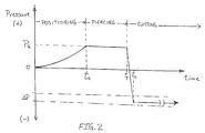
- the pressure sensor 42 generates and provides to the controlling unit 30 an output signal 43 similar to that shown in Fig. 2 indicating the pressure condition inside the nozzle shield 15 as a function of time.
- the controlling unit 30 generates a control signal 11 instructing motion equipment (not shown) to a lower nozzle assembly in Step 120 to form an air gap 17 having a predetermined height.
- the nozzle shield 15 is set to establish a stand-off distance (i.e., the distance between the focussing tube 14 and workpiece 16) which is about equal to the air gap 17, once the air gap 17 is established. This is accomplished by using the pressure sensor 42 as a proximity switch which monitors in Step 130 the pressure increase caused by the restriction created between the workpiece 16 and nozzle shield 15 as it moves toward the target surface. As shown in Fig. 2, the pressure inside the nozzle shield 15 increases to a predetermined pressure P g which is programmed into the controlling unit 30 and corresponds to the pressure at which the desired air gap 17 is formed.
- Step 130 detects that the nozzle assembly 10 is in position
- the controlling unit 30 generates a control signal to stop the motion of the nozzle assembly 10 thereby setting the cutting position (i.e. stand-off distance) and the controlling unit 30 also records this position.
- the thickness of the workpiece 16 may be measured in Step 140. This is accomplished by using the controlling unit 30 to compare the height of the nozzle assembly in the cutting position set in Steps 120 and 130 with a known reference position. The measured thickness of the workpiece 16 is inputted into the controlling unit 30 for performing calculations necessary for determining the proper operating conditions. For example, the proper traverse cutting speed at which a waterjet cuts through a particular material during an AWJ cutting operation varies indirectly with and may be calculated using workpiece thickness according to the equation disclosed in the article by J. Zeng and J.P. Munoz titled "Intelligent Automation of AWJ Cutting for Efficient Production", Proceedings of the 12th International Symposium on Jet Cutting Technology, BHRA, Rouen, France, 1994, pp. 401-408.
- Step 150 the controlling unit 30 simultaneously generates control signals 21 and 19 to initiate, respectively, the supply of high pressure water from the water source 22 and abrasive from the vibration feeder 20 to establish an abrasive water jet in the water nozzle assembly 10.
- the controlling unit 30 sends a control signal 11 to move the nozzle assembly 10 preferably at a constant rate (e.g. 50 inches per minute - 127cm/min) along a circle which has a radius equal to the focussing tube diameter until the workpiece is pierced.
- a constant rate e.g. 50 inches per minute - 127cm/min
- the moment the waterjet pierces the workpiece 16 is first detected. According to the embodiment shown in Fig. 1, this is accomplished by the air supply 40 maintaining a steady flow of air to the nozzle shield 15 during the time the piercing operation is being performed.
- the pressure sensor 42 simultaneously monitors and provides a steady output signal 43 to the controlling unit 30 as represented by the horizontal signal between the "t g " and T p " shown in Fig. 2.
- a vacuum is created within the nozzle shield 15 which, as shown in Fig. 2, causes a virtually instantaneous drop in the pressure detected by the pressure sensor 42 at "t p ", which is the moment pierce-through occurs.
- Step 190 Upon detecting the decrease in pressure in Step 160 caused upon pierce-through, the desired cutting operation is then initiated in Step 190 by the controlling unit 30 which either sends a control signal 11 to begin horizontal movement of the nozzle assembly 10, sends a control signal 26 to begin horizontal movement of the workpiece 16, or both, to move the nozzle assembly 10 laterally at the calculated cutting speed relative to the workpiece 16, which cutting speed may be calculated as discussed above.
- the cutting operation is monitored in Step 200 either visually or automatically (e.g. by a mechanical sensor switch) to detect when the cutting operation is complete.
- the air gap 17 between the nozzle assembly 10 and workpiece 16 is preferably monitored in Step 210 for any changes by monitoring the signal provided by the pressure sensor 42 for any variation in the signal after time "t c " which represents the time at which pierce-through is completed and cutting begins as shown in Fig. 2.
- a predetermined pressure range represented as “ ⁇ P” in Fig. 2
- the controlling unit 30 may be programmed to send an error signal via connections 19 and 21 to respectively stop the flow of abrasive and water to interrupt the AWJ operation being performed.
- a typical device includes, but is not limited to, a Model OKC-424 Air Proximity Sensor available from O'Keefe Controls Co., Monroe, CT, U.S.A.
- a number of advantages in sensing various physical aspects of machining processes such as AWJ cutting processes may be achieved. among these advantages are the ability to determine and monitor various physical dimensions of and the proximity and distances between various apparatus and workpiece components.
- various measurement functions may be automatically accomplished using the multi-functional sensing method and apparatus including proximity detection of the waterjet nozzle, measuring the thickness of a workpiece and real time monitoring and correction of nozzle stand-off distance.
- physical events such as pierce-through of a workpiece may also be detected using the multi-functional sensing method and apparatus.
- the multi-functional sensing method and apparatus when used in conjunction with a CNC controlling unit, facilitates the automatic programming, calculating, and control of various machining parameters and operating conditions without the need for any user interference or interface while also increasing the accuracy of the operating parameters and conditions so determined. Additionally, changes in process parameters (e.g., cutting speed, changes in water pressure, abrasive flow rate, abrasive type, nozzle diameter, etc.) may also be made automatically based on sensed condition changes (e.g. different workpiece thicknesses) using the present multi-functional sensing methods and apparatus.
- process parameters e.g., cutting speed, changes in water pressure, abrasive flow rate, abrasive type, nozzle diameter, etc.
- sensed condition changes e.g. different workpiece thicknesses
- the sensing method and apparatus may be employed to monitor a variety of other machining processes which can incorporate any variety of piercing motions and energy beam machining technologies.
- piercing motion patterns examples include a linear, back-and-forth, star, wiggle or other pattern.
- energy beam processes including AWJ may be used to perform a variety of other AWJ and traditional operations such as piercing, drilling, milling and turning operations.
- Such energy beam technologies include those which utilise a concentrated beam energy to effect material removal to cut or otherwise make, shape, prepare or finish (i.e. machine) a raw stock material into a finished material.
- the sensing method and apparatus may be used with and incorporated into other types of energy beam technologies, including pure waterjet, laser, plasma arc, flame cutting and electron beam technologies. Although each of these use different physical phenomena to remove material, they behave similarly in nature and methodology to a waterjet energy beam such that the present sensing method and apparatus may be employed.
Abstract
Description
- This invention relates generally to sensing methods and apparatus and more particularly to methods and apparatus for monitoring abrasive waterjet machining of engineering materials.
- Abrasive water jet (AWJ) processes employ materials entrained into a high-pressure waterjet to perform a variety of cutting and other machinery operations on a variety of materials. The high-energy waterjet beam utilised combines a rapid erosion of a workpiece material by high speed solid particle impacts with rapid cooling provided by a waterjet. In AWJ cutting operations an abrasive waterjet pierces through the thickness of and is then moved along a material to be cut.
- In performing machining operations such as AWJ cutting, various physical dimensions such as workpiece thickness must be measured in order to properly configure the water pressure, abrasive flow rate and other system parameters for the AWJ apparatus. Additionally, the proximity of and distances between various components of the AWJ apparatus and the workpiece must be monitored. For example, the proximity of an AWJ nozzle to a workpiece must be monitored with respect to establishing and maintaining air gap and stand-off distances within acceptable tolerance ranges. Additionally physical events such as the moment of pierce-through of a workpiece by an AWJ waterjet during a cutting operation must also be detected in order to establish when the relative motion between the workpiece and an AWJ nozzle should be commenced.
- Although the measuring and monitoring of these and other physical aspects may be done by visual inspection and manual control by an operator, this is generally a cumbersome and not very precise method for controlling such machining operations.
- According to one aspect of the present invention, there is provided an apparatus for sensing a pierce-through condition of a material made by a piercing force, comprising a shield means for surrounding a source of said piercing force, a means for supplying a gas to create a pressure within said shield means, and a sensing means for detecting a decrease in pressure caused within said shield means by said pierce-through condition created by said piercing force.
- According to a second aspect of the present invention, there is provided an apparatus for detecting the distance between a nozzle assembly for a machining process and a workpiece to be machined, comprising a shield means for surrounding a nozzle assembly, said shield means being open at one end to permit a piercing force from said nozzle assembly to exit said shield means, a means for supplying a gas to create a pressure within said shield means, and a sensing means for detecting an increase in pressure caused within said shield means as said open end of said shield means approaches the workpiece to be machined.
- According to a third aspect of the present invention, there is provided a method of sensing a pierce-through condition of a material made by a piercing force, comprising the steps of supplying a gas to create a pressure within a shield means surrounding a source of a piercing force, and detecting a decrease in pressure caused within said shield means by said pierce-through condition created by said piercing force.
- According to a fourth aspect of the present invention, there is provided a method of detecting the distance between a nozzle assembly for a machining process and a workpiece to be machined, comprising supplying a gas to create a pressure within a shield means surrounding a nozzle assembly, said shield means being open at one end to permit a piercing force from said nozzle assembly to exit said shield means, and detecting an increase in pressure caused within said shield means as said open end of said shield means approaches a workpiece to be machined.
- For a better understanding of the invention and to show how the same may be carried into effect, reference will now be made, by way of example, to the accompanying drawings, in which:-
- Fig. 1 is a general diagram of the components of an abrasive waterjet system;
- Fig. 2 is a representation of a pressure signal read by a pressure sensor during a cutting method performed; and
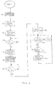
- Fig. 3 is a program flow chart for a software process resident in the programmable controlling unit of Fig. 1 for performing a cutting method using a sensing apparatus.
-
- Fig. 1 shows a broad system diagram of an embodiment as applied to an abrasive waterjet (AWJ) system. Briefly, shown in Fig. 1 is a
nozzle assembly 10 comprising anorifice 12 and a focussing tube 14 which applies a mixture of high pressure water and abrasive to a movingworkpiece 16. Thenozzle assembly 10 is preferably supplied with abrasive from anoptional vibration feeder 20 and high pressure water from awater source 22. Although shown using a vibration feeder, other types of feeding devices may be used for this purpose. - A controlling unit 30 is typically provided for receiving input on the operating conditions of the AWJ system and controlling the motion of the
nozzle assembly 10 andworkpiece 16. The controlling unit 30 is preferably a Computerised Numerical Controller (CNC) which is available and may include, e.g. a Model ACR 2000 motion controller from Acroloop Motion Control Systems, Inc., Chanhassen, MN, U.S.A. - Prior to performing an AWJ cutting or other machining operation, the controlling unit 30 is preset by a user with AWJ system operating parameters such as water pressure, abrasive particle size, abrasive flow rate and the dimensions of the waterjet nozzle orifice. These parameters are varied depending on the type of workpiece material and the type of machining operation to be performed. In operation, the controlling unit 30 controls the feed from the
vibration feeder 20 and the feed supply of high pressure water from thewater source 22. As high pressure water and abrasives are supplied to the nozzle, theworkpiece 16 is moved back and forth by positioning equipment (not shown) which manoeuvres the workpiece at the proper traverse speed for the desired cutting or other machining operation. Preferably, the positioning equipment is responsive to and controlled by acontrol signal 26 provided by the controlling unit 30, which may also be used to calculate the traverse speed. - Shown in Fig. 1 on the
nozzle assembly 10 is the multi-functional sensing apparatus which comprises anozzle shield 15 surrounding the focussing tube 14. Thenozzle shield 15 is connected to and in fluid communication with an air orother gas supply 40 via aconduit 41. Apressure sensor 42 is connected to theconduit 41 and located between thenozzle shield 15 andair supply 40 for sensing the pressure conditions inside thenozzle shield 15 and providing apressure sensor signal 43 to the controlling unit 30. - Operation of the AWJ apparatus shown in Fig. 1 will now be described with respect to performing an AWJ cutting operation according to the present automated sensing method. Turning to the flow diagram in Fig. 3, the controlling unit 30 is activated in
Step 100 in inputting the specific AWJ system operating parameters required by the controlling unit 30 prior to beginning an AWJ cutting cycle. As described above these operation parameters typically include water pressure, abrasive particle size, abrasive flow rate and the dimensions of the waterjet nozzle orifice. - The controlling unit 30, upon receiving a user instruction to begin a cutting sequence, begins a piercing cycle in
Step 110 by generating acontrol signal 39 inStep 110 to theair supply 40 thereby initiating airflow into thenozzle shield 15 via theconduit 41. Thepressure sensor 42 generates and provides to the controlling unit 30 anoutput signal 43 similar to that shown in Fig. 2 indicating the pressure condition inside thenozzle shield 15 as a function of time. The controlling unit 30 generates a control signal 11 instructing motion equipment (not shown) to a lower nozzle assembly inStep 120 to form anair gap 17 having a predetermined height. - For a cutting operation, the
nozzle shield 15 is set to establish a stand-off distance (i.e., the distance between the focussing tube 14 and workpiece 16) which is about equal to theair gap 17, once theair gap 17 is established. This is accomplished by using thepressure sensor 42 as a proximity switch which monitors inStep 130 the pressure increase caused by the restriction created between theworkpiece 16 andnozzle shield 15 as it moves toward the target surface. As shown in Fig. 2, the pressure inside thenozzle shield 15 increases to a predetermined pressure Pg which is programmed into the controlling unit 30 and corresponds to the pressure at which the desiredair gap 17 is formed. At this point, whenStep 130 detects that thenozzle assembly 10 is in position, the controlling unit 30 generates a control signal to stop the motion of thenozzle assembly 10 thereby setting the cutting position (i.e. stand-off distance) and the controlling unit 30 also records this position. - The thickness of the
workpiece 16 may be measured in Step 140. This is accomplished by using the controlling unit 30 to compare the height of the nozzle assembly in the cutting position set inSteps workpiece 16 is inputted into the controlling unit 30 for performing calculations necessary for determining the proper operating conditions. For example, the proper traverse cutting speed at which a waterjet cuts through a particular material during an AWJ cutting operation varies indirectly with and may be calculated using workpiece thickness according to the equation disclosed in the article by J. Zeng and J.P. Munoz titled "Intelligent Automation of AWJ Cutting for Efficient Production", Proceedings of the 12th International Symposium on Jet Cutting Technology, BHRA, Rouen, France, 1994, pp. 401-408. - In
Step 150, the controlling unit 30 simultaneously generatescontrol signals 21 and 19 to initiate, respectively, the supply of high pressure water from thewater source 22 and abrasive from thevibration feeder 20 to establish an abrasive water jet in thewater nozzle assembly 10. The controlling unit 30 sends a control signal 11 to move thenozzle assembly 10 preferably at a constant rate (e.g. 50 inches per minute - 127cm/min) along a circle which has a radius equal to the focussing tube diameter until the workpiece is pierced. - Prior to commencing a traverse cutting motion of the
nozzle assembly 10 across theworkpiece 16, the moment the waterjet pierces theworkpiece 16 is first detected. According to the embodiment shown in Fig. 1, this is accomplished by theair supply 40 maintaining a steady flow of air to thenozzle shield 15 during the time the piercing operation is being performed. Thepressure sensor 42 simultaneously monitors and provides asteady output signal 43 to the controlling unit 30 as represented by the horizontal signal between the "tg" and Tp" shown in Fig. 2. Upon penetration (i.e. "pierce-through"), of the waterjet through theworkpiece 16, a vacuum is created within thenozzle shield 15 which, as shown in Fig. 2, causes a virtually instantaneous drop in the pressure detected by thepressure sensor 42 at "tp", which is the moment pierce-through occurs. - Upon detecting the decrease in pressure in Step 160 caused upon pierce-through, the desired cutting operation is then initiated in
Step 190 by the controlling unit 30 which either sends a control signal 11 to begin horizontal movement of thenozzle assembly 10, sends acontrol signal 26 to begin horizontal movement of theworkpiece 16, or both, to move thenozzle assembly 10 laterally at the calculated cutting speed relative to theworkpiece 16, which cutting speed may be calculated as discussed above. The cutting operation is monitored inStep 200 either visually or automatically (e.g. by a mechanical sensor switch) to detect when the cutting operation is complete. - During the cutting operation, the
air gap 17 between thenozzle assembly 10 andworkpiece 16 is preferably monitored in Step 210 for any changes by monitoring the signal provided by thepressure sensor 42 for any variation in the signal after time "tc" which represents the time at which pierce-through is completed and cutting begins as shown in Fig. 2. Should any variation above or below a predetermined pressure range (represented as "ΔP" in Fig. 2), which range corresponds to an acceptable stand-off distance tolerance, an error signal is sent by the controlling unit 30 via connection 11 to implement compensation inStep 220 by the motion equipment to adjust the stand-off distance. Alternatively, the controlling unit 30 may be programmed to send an error signal viaconnections 19 and 21 to respectively stop the flow of abrasive and water to interrupt the AWJ operation being performed. - With respect to devices which may be incorporated as
pressure sensor 42, any sensor which can detect the increase and decrease of pressure withinnozzle shield 15, as described above, may be incorporated. A typical device includes, but is not limited to, a Model OKC-424 Air Proximity Sensor available from O'Keefe Controls Co., Monroe, CT, U.S.A. - As a result of the multi-functional sensing method and apparatus, a number of advantages in sensing various physical aspects of machining processes such as AWJ cutting processes may be achieved. among these advantages are the ability to determine and monitor various physical dimensions of and the proximity and distances between various apparatus and workpiece components. For example, various measurement functions may be automatically accomplished using the multi-functional sensing method and apparatus including proximity detection of the waterjet nozzle, measuring the thickness of a workpiece and real time monitoring and correction of nozzle stand-off distance. Additionally, physical events such as pierce-through of a workpiece may also be detected using the multi-functional sensing method and apparatus.
- Moreover, when used in conjunction with a CNC controlling unit, the multi-functional sensing method and apparatus facilitates the automatic programming, calculating, and control of various machining parameters and operating conditions without the need for any user interference or interface while also increasing the accuracy of the operating parameters and conditions so determined. Additionally, changes in process parameters (e.g., cutting speed, changes in water pressure, abrasive flow rate, abrasive type, nozzle diameter, etc.) may also be made automatically based on sensed condition changes (e.g. different workpiece thicknesses) using the present multi-functional sensing methods and apparatus.
- Although described above with respect to monitoring an AWJ cutting operation using an AWJ waterjet moved through a circular motion, it is expected that the sensing method and apparatus may be employed to monitor a variety of other machining processes which can incorporate any variety of piercing motions and energy beam machining technologies.
- Examples of other piercing motion patterns may be used include a linear, back-and-forth, star, wiggle or other pattern. Additionally, it is further envisaged that the energy beam processes including AWJ may be used to perform a variety of other AWJ and traditional operations such as piercing, drilling, milling and turning operations.
- Such energy beam technologies include those which utilise a concentrated beam energy to effect material removal to cut or otherwise make, shape, prepare or finish (i.e. machine) a raw stock material into a finished material. By way of example, it is envisaged that the sensing method and apparatus may be used with and incorporated into other types of energy beam technologies, including pure waterjet, laser, plasma arc, flame cutting and electron beam technologies. Although each of these use different physical phenomena to remove material, they behave similarly in nature and methodology to a waterjet energy beam such that the present sensing method and apparatus may be employed.
Claims (15)
- An apparatus for sensing a pierce-through condition of a material made by a piercing force, comprising a shield means (15) for surrounding a source of said piercing force, a means (40) for supplying a gas to create a pressure within said shield means, and a sensing means (42) for detecting a decrease in pressure caused within said shield means by said pierce-through condition created by said piercing force.
- An apparatus for detecting the distance between a nozzle assembly (10) for a machining process and a workpiece (16) to be machined, comprising a shield means (15) for surrounding a nozzle assembly, said shield means being open at one end to permit a piercing force from said nozzle assembly to exit said shield means, a means (40) for supplying a gas to create a pressure within said shield means, and a sensing means (42) for detecting an increase in pressure caused within said shield mans as said open end of said shield means approaches the workpiece (16) to be machined.
- An apparatus according to claim 1 or 2, wherein said sensing means (42) is disposed between and in fluid communication with said means (40) for supplying gas and said shield means (15).
- An apparatus according to claim 2, further comprising a controlling means (30) which monitors said sensing means (42) and detects when said pressure within said shield means (15) reaches a pressure which corresponds to a predetermined gap distance (17) between said nozzle assembly (10) and said workpiece (16) for a machining process.
- An apparatus according to claim 4, wherein said controlling means (30) also monitors the position of said nozzle assembly (10) upon establishing said gap distance (17) and compares this position with a predetermined reference position to determine a thickness of said workpiece.
- An apparatus according to claim 2, further comprising controlling means (30) which monitors said sensing means (42) and detects when said pressure within said shield means (15) varies outside of a pressure range, said range corresponding to an acceptable predetermined range of gap distances (17) between said nozzle assembly (10) and said workpiece (16) for a machining process.
- An apparatus according to any one of the preceding claims, wherein said piercing force is a concentrated beam energy selected from the group consisting of an abrasive waterjet, a pure waterjet, a laser, a plasma arc, a flame and an electron beam.
- An apparatus according to any one of the preceding claims, wherein said piercing force performs a machining operation selected from the group consisting of a cutting, a piercing, a drilling, a milling and a turning operation or any combination thereof.
- A method of sensing a pierce-through condition of a material made by a piercing force, comprising the steps of supplying a gas to create a pressure within a shield means (15) surrounding a source of a piercing force, and detecting a decrease in pressure caused within said shield means (15) by said pierce-through condition created by said piercing force.
- A method of detecting the distance between a nozzle assembly (10) for a machining process and a workpiece to be machined, comprising supplying a gas to create a pressure within a shield means (16) surrounding a nozzle assembly, said shield means being open at one end to permit a piercing force from said nozzle assembly (10) to exit said shield means, and detecting an increase in pressure caused within said shield means as said open end of said shield means approaches a workpiece (16) to be machined.
- A method according to claim 10, further comprising the steps of monitoring said increase in pressure within said shield means (15) and detecting when said pressure reaches a pressure which corresponds to a predetermined gap distance (17) between nozzle assembly (10) and said workpiece (16) for a machining process.
- A method according to claim 11, wherein said monitoring step further comprises monitoring a position of said nozzle assembly (10) upon establishing said gap distance (17) and comparing this position with a predetermined reference position to determine a thickness of said workpiece.
- A method according to claim 10, further comprising the steps of monitoring said sensing means (42) and detecting when said pressure within said shield means (15) varies outside of a pressure range, said range corresponding to an acceptable predetermined range of gap distances (17) between nozzle assembly (15) and said workpiece (16) for a machining process.
- A method according to any one of claims 9 to 13, wherein said piercing force is a concentrated beam energy selected from the group consisting of an abrasive waterjet, a pure waterjet, a laser, a plasma arc, a flame and an electron beam.
- A method according to any one of claims 9 to 14, wherein said piercing force performs a machining operation selected from the group consisting of a cutting, a piercing, a drilling, a milling and a turning operation or any combination thereof.
Applications Claiming Priority (2)
| Application Number | Priority Date | Filing Date | Title |
|---|---|---|---|
| US143678 | 1998-08-31 | ||
| US09/143,678 US6244927B1 (en) | 1998-08-31 | 1998-08-31 | Multi-functional sensing methods and apparatus therefor |
Publications (2)
| Publication Number | Publication Date |
|---|---|
| EP0985491A2 true EP0985491A2 (en) | 2000-03-15 |
| EP0985491A3 EP0985491A3 (en) | 2001-01-24 |
Family
ID=22505112
Family Applications (1)
| Application Number | Title | Priority Date | Filing Date |
|---|---|---|---|
| EP99306818A Withdrawn EP0985491A3 (en) | 1998-08-31 | 1999-08-27 | Method and apparatus for machining a workpiece by piercing |
Country Status (3)
| Country | Link |
|---|---|
| US (1) | US6244927B1 (en) |
| EP (1) | EP0985491A3 (en) |
| JP (1) | JP2000088559A (en) |
Cited By (6)
| Publication number | Priority date | Publication date | Assignee | Title |
|---|---|---|---|---|
| WO2003011477A1 (en) * | 2001-07-31 | 2003-02-13 | Robert Bosch Gmbh | Device for applying a free-flowing medium to the surface of a substrate |
| CN102380829A (en) * | 2010-08-31 | 2012-03-21 | 鸿富锦精密工业(深圳)有限公司 | Sand spraying device and pattern forming method |
| CN102528299A (en) * | 2010-09-16 | 2012-07-04 | 通快机床两合公司 | Method for checking gas nozzle arranged in laser processing machine and attached laser processing machine |
| EP2698228A1 (en) * | 2011-04-13 | 2014-02-19 | Mitsubishi Heavy Industries, Ltd. | Abrasive water jet machining device |
| CN109540717A (en) * | 2018-11-20 | 2019-03-29 | 常州大学 | A kind of straight well double-wall drill pipe flushes corrosion experimental device and experimental method |
| CN112692908A (en) * | 2020-12-08 | 2021-04-23 | 苏州维嘉科技股份有限公司 | Presser foot pressure adjusting system and method and drilling machine |
Families Citing this family (23)
| Publication number | Priority date | Publication date | Assignee | Title |
|---|---|---|---|---|
| DE10113599A1 (en) * | 2001-03-20 | 2002-10-02 | Fisba Optik Ag St Gallen | Device for the abrasive processing of surfaces of optical elements |
| JP3896265B2 (en) * | 2001-09-11 | 2007-03-22 | オリンパス株式会社 | Positioning jig and spray polishing apparatus using positioning jig |
| DE50109276D1 (en) * | 2001-12-06 | 2006-05-11 | Schmall Karl Heinz | Water jet cutting machine with non-contact and optionally tactile distance guide sensor device |
| US6769956B1 (en) | 2002-02-04 | 2004-08-03 | Oberg Industries | Apparatus and method for rapid, precise positioning of a grit-blasting nozzle |
| US20040043704A1 (en) * | 2002-08-30 | 2004-03-04 | Mark Saberton | Method and apparatus for high speed cutting |
| JP5257745B2 (en) * | 2008-03-19 | 2013-08-07 | 澁谷工業株式会社 | Laser processing method and apparatus |
| EP2243594A1 (en) * | 2009-04-20 | 2010-10-27 | Univerza v Ljubljani | Arrangement of devices and a method for empirically determining efficiency index in abrasive waterjet cutting and application thereof in a device for simultaneous control of abrasive waterjet cutting |
| US8389066B2 (en) * | 2010-04-13 | 2013-03-05 | Vln Advanced Technologies, Inc. | Apparatus and method for prepping a surface using a coating particle entrained in a pulsed waterjet or airjet |
| JP5698960B2 (en) * | 2010-11-10 | 2015-04-08 | 小池酸素工業株式会社 | Cutting method and cutting apparatus for workpiece |
| US8506361B2 (en) * | 2011-08-25 | 2013-08-13 | General Electric Company | Fixture to facilitate sandblasting of a cylindrical object |
| US9095955B2 (en) | 2012-08-16 | 2015-08-04 | Omax Corporation | Control valves for waterjet systems and related devices, systems and methods |
| US8904912B2 (en) | 2012-08-16 | 2014-12-09 | Omax Corporation | Control valves for waterjet systems and related devices, systems, and methods |
| CH707367A8 (en) * | 2012-12-18 | 2014-12-15 | Micromachining Ag | Method for processing a sequence of workpieces by means of at least one processing beam. |
| US9573289B2 (en) | 2013-10-28 | 2017-02-21 | Flow International Corporation | Fluid jet cutting systems |
| CN105312781A (en) * | 2014-12-08 | 2016-02-10 | 牛得草 | Method for detecting whether materials are penetrated or not by using change of gas pressure or flow |
| US10252400B1 (en) | 2015-09-29 | 2019-04-09 | Flow International Corporation | Methods for improving jet cutting performance via force sensing |
| CA2999011C (en) | 2017-03-24 | 2020-04-21 | Vln Advanced Technologies Inc. | Compact ultrasonically pulsed waterjet nozzle |
| US10987759B2 (en) * | 2017-05-31 | 2021-04-27 | Zhaoli Hu | Advanced back-strike protection process and related devices for water jet guided laser process |
| US11554461B1 (en) | 2018-02-13 | 2023-01-17 | Omax Corporation | Articulating apparatus of a waterjet system and related technology |
| US20210204387A1 (en) * | 2019-12-31 | 2021-07-01 | The Esab Group Inc. | Methods for operating a plasma torch |
| KR20230005840A (en) | 2020-03-30 | 2023-01-10 | 하이퍼썸, 인크. | Cylinder for liquid jet pump with multifunctional connecting longitudinal ends |
| KR20220090297A (en) * | 2020-12-22 | 2022-06-29 | 코닝 인코포레이티드 | Composite substrate cutting apparatus and method of cutting composite substrate |
| CN216096986U (en) * | 2021-10-29 | 2022-03-22 | 宁德时代新能源科技股份有限公司 | Welding equipment |
Citations (3)
| Publication number | Priority date | Publication date | Assignee | Title |
|---|---|---|---|---|
| US5089685A (en) * | 1989-12-21 | 1992-02-18 | Robert Bosch Gmbh | Method of and arrangement for measuring the size of throughgoing openings |
| DE4219423C1 (en) * | 1992-06-11 | 1993-11-11 | Siemens Ag | Three=dimensional workpiece structuring device using particle beam - uses detected pressure of particle beam to control position of jet relative to workpiece |
| EP0713745A1 (en) * | 1994-11-15 | 1996-05-29 | ROLLS-ROYCE plc | A method and apparatus for producing apertured components |
Family Cites Families (16)
| Publication number | Priority date | Publication date | Assignee | Title |
|---|---|---|---|---|
| US3516204A (en) | 1967-08-21 | 1970-06-23 | Pennwalt Corp | Abrading apparatus |
| US3769753A (en) * | 1972-03-16 | 1973-11-06 | H Fleischer | Automatic car sand blaster |
| US3994079A (en) | 1975-03-31 | 1976-11-30 | Simone Mirman Limited | Display device, particularly suitable for interior designs |
| US4412402A (en) | 1978-07-28 | 1983-11-01 | Cavitron Inc. | Equipment and method for delivering an abrasive-laden gas stream |
| US4380138A (en) | 1981-04-13 | 1983-04-19 | International Harvester Co. | Abrasive liquid jet cutting |
| JPS614670A (en) | 1984-06-20 | 1986-01-10 | Ryoji Kobayashi | Cutting method by superhigh-speed abrasive powder fluid jet |
| JPS61111884A (en) | 1984-11-06 | 1986-05-29 | Niigata Eng Co Ltd | Machining method by sand blast |
| US4941955A (en) | 1987-07-06 | 1990-07-17 | The Interlake Companies, Inc. | Apparatus and method for electrochemical machining of flat plates or sheets |
| US4966059A (en) | 1987-09-22 | 1990-10-30 | First Brands Corporation | Apparatus and process for high speed waterjet cutting of extensible sheeting |
| US5207533A (en) | 1990-02-01 | 1993-05-04 | Gaz De France | Process and device for replacing an underground pipe |
| JPH03285783A (en) * | 1990-04-03 | 1991-12-16 | Mitsubishi Electric Corp | Laser cutting and processing device |
| US5166885A (en) | 1991-01-28 | 1992-11-24 | General Electric Company | Non-destructive monitoring of surfaces by 3-D profilometry using a power spectra |
| US5222332A (en) * | 1991-04-10 | 1993-06-29 | Mains Jr Gilbert L | Method for material removal |
| US5319894A (en) * | 1992-10-08 | 1994-06-14 | Church & Dwight Co., Inc. | Blast nozzle containing water atomizer for dust control |
| JP2868384B2 (en) | 1993-02-23 | 1999-03-10 | 株式会社東京精密 | Dicing groove depth measuring method and dicing device |
| US5700181A (en) * | 1993-09-24 | 1997-12-23 | Eastman Kodak Company | Abrasive-liquid polishing and compensating nozzle |
-
1998
- 1998-08-31 US US09/143,678 patent/US6244927B1/en not_active Expired - Fee Related
-
1999
- 1999-08-27 EP EP99306818A patent/EP0985491A3/en not_active Withdrawn
- 1999-08-31 JP JP11244214A patent/JP2000088559A/en active Pending
Patent Citations (3)
| Publication number | Priority date | Publication date | Assignee | Title |
|---|---|---|---|---|
| US5089685A (en) * | 1989-12-21 | 1992-02-18 | Robert Bosch Gmbh | Method of and arrangement for measuring the size of throughgoing openings |
| DE4219423C1 (en) * | 1992-06-11 | 1993-11-11 | Siemens Ag | Three=dimensional workpiece structuring device using particle beam - uses detected pressure of particle beam to control position of jet relative to workpiece |
| EP0713745A1 (en) * | 1994-11-15 | 1996-05-29 | ROLLS-ROYCE plc | A method and apparatus for producing apertured components |
Non-Patent Citations (2)
| Title |
|---|
| ALKIRE T D: "THE FUTURE OF WATERJET CUTTING" MANUFACTURING TECHNOLOGY INTERNATIONAL,GB,STERLING PUBLICATIONS LTD. LONDON, 1990, pages 201-202,204, XP000178307 ISSN: 0950-4451 * |
| PATENT ABSTRACTS OF JAPAN vol. 016, no. 119 (M-1225), 25 March 1992 (1992-03-25) & JP 03 285783 A (MITSUBISHI ELECTRIC CORP), 16 December 1991 (1991-12-16) * |
Cited By (9)
| Publication number | Priority date | Publication date | Assignee | Title |
|---|---|---|---|---|
| WO2003011477A1 (en) * | 2001-07-31 | 2003-02-13 | Robert Bosch Gmbh | Device for applying a free-flowing medium to the surface of a substrate |
| CN102380829A (en) * | 2010-08-31 | 2012-03-21 | 鸿富锦精密工业(深圳)有限公司 | Sand spraying device and pattern forming method |
| CN102528299A (en) * | 2010-09-16 | 2012-07-04 | 通快机床两合公司 | Method for checking gas nozzle arranged in laser processing machine and attached laser processing machine |
| CN102528299B (en) * | 2010-09-16 | 2015-01-28 | 通快机床两合公司 | Method for checking gas nozzle arranged in laser processing machine and attached laser processing machine |
| EP2698228A1 (en) * | 2011-04-13 | 2014-02-19 | Mitsubishi Heavy Industries, Ltd. | Abrasive water jet machining device |
| EP2698228A4 (en) * | 2011-04-13 | 2015-04-01 | Mitsubishi Heavy Ind Ltd | Abrasive water jet machining device |
| US9193036B2 (en) | 2011-04-13 | 2015-11-24 | Mitsubishi Heavy Industries, Ltd | Abrasive water-jet machining device |
| CN109540717A (en) * | 2018-11-20 | 2019-03-29 | 常州大学 | A kind of straight well double-wall drill pipe flushes corrosion experimental device and experimental method |
| CN112692908A (en) * | 2020-12-08 | 2021-04-23 | 苏州维嘉科技股份有限公司 | Presser foot pressure adjusting system and method and drilling machine |
Also Published As
| Publication number | Publication date |
|---|---|
| EP0985491A3 (en) | 2001-01-24 |
| US6244927B1 (en) | 2001-06-12 |
| JP2000088559A (en) | 2000-03-31 |
Similar Documents
| Publication | Publication Date | Title |
|---|---|---|
| US6244927B1 (en) | Multi-functional sensing methods and apparatus therefor | |
| US6120351A (en) | Automatic machinability measuring and machining methods and apparatus therefor | |
| EP0984264A2 (en) | Method and apparatus for measuring machinability and machining speed of a material | |
| US9446472B2 (en) | System and method for integrated controller | |
| US9073142B2 (en) | Plasma torch cutting device and process | |
| US20200254554A1 (en) | Method and apparatus for eliminating cut taper | |
| CA2626128C (en) | Automated welding of moulds and stamping tools | |
| US11883895B2 (en) | System and methods for improved sheet metal cutting | |
| CN106903385B (en) | Wire electric discharge machine | |
| CN116088426B (en) | Machining center motion positioning protection system with vision device | |
| US6008465A (en) | Laser cutting machine and method for laser cutting with measurement of resistance between cutting head and work piece | |
| AU759759B2 (en) | Method of cutting a workpiece along an arcuate path with a plasma arc torch | |
| JP5023919B2 (en) | Machine Tools | |
| US20230064501A1 (en) | Edge shaping using material processing systems | |
| US20190134768A1 (en) | Method and apparatus for water jet cutting standoff height | |
| JP2000339011A (en) | Three-dimensional linear finishing machine and production control method for machining program of the finishing machine | |
| JPH01153299A (en) | Detector in water jet machining | |
| JP3023394B2 (en) | Electric discharge machine for drilling | |
| JPH03285783A (en) | Laser cutting and processing device | |
| JPS59144571A (en) | Automatic edge preparing method of three-dimensional curved surface | |
| EP2412498A1 (en) | Anti-collision device for a water jet cutting head | |
| Vander Wert | Advances in lasers and laser systems for processing 3D metal parts | |
| JP2000042774A (en) | Laser machining method and its device | |
| JP2003181670A (en) | Laser machining equipment and control method for jog cutting | |
| JPH11226847A (en) | Operation method of metal machining device provided with cutting tool automatic replacing means |
Legal Events
| Date | Code | Title | Description |
|---|---|---|---|
| PUAI | Public reference made under article 153(3) epc to a published international application that has entered the european phase |
Free format text: ORIGINAL CODE: 0009012 |
|
| AK | Designated contracting states |
Kind code of ref document: A2 Designated state(s): DE IT SE |
|
| AX | Request for extension of the european patent |
Free format text: AL;LT;LV;MK;RO;SI |
|
| PUAL | Search report despatched |
Free format text: ORIGINAL CODE: 0009013 |
|
| AK | Designated contracting states |
Kind code of ref document: A3 Designated state(s): AT BE CH CY DE DK ES FI FR GB GR IE IT LI LU MC NL PT SE |
|
| AX | Request for extension of the european patent |
Free format text: AL;LT;LV;MK;RO;SI |
|
| RIC1 | Information provided on ipc code assigned before grant |
Free format text: 7G 01N 3/58 A, 7G 01N 3/56 B, 7B 24C 1/04 B, 7B 23Q 15/007 B |
|
| 17P | Request for examination filed |
Effective date: 20010402 |
|
| AKX | Designation fees paid |
Free format text: DE IT SE |
|
| 17Q | First examination report despatched |
Effective date: 20031016 |
|
| STAA | Information on the status of an ep patent application or granted ep patent |
Free format text: STATUS: THE APPLICATION IS DEEMED TO BE WITHDRAWN |
|
| 18D | Application deemed to be withdrawn |
Effective date: 20040427 |