EP0988092B1 - Applicateur intratissulaire ultrasonore pour l'hyperthermie - Google Patents
Applicateur intratissulaire ultrasonore pour l'hyperthermie Download PDFInfo
- Publication number
- EP0988092B1 EP0988092B1 EP98930828A EP98930828A EP0988092B1 EP 0988092 B1 EP0988092 B1 EP 0988092B1 EP 98930828 A EP98930828 A EP 98930828A EP 98930828 A EP98930828 A EP 98930828A EP 0988092 B1 EP0988092 B1 EP 0988092B1
- Authority
- EP
- European Patent Office
- Prior art keywords
- head
- transducer
- applicator according
- ultrasound
- planar
- Prior art date
- Legal status (The legal status is an assumption and is not a legal conclusion. Google has not performed a legal analysis and makes no representation as to the accuracy of the status listed.)
- Expired - Lifetime
Links
- 238000002604 ultrasonography Methods 0.000 title claims abstract description 21
- 238000000015 thermotherapy Methods 0.000 title 1
- 239000012528 membrane Substances 0.000 claims abstract description 19
- 238000010438 heat treatment Methods 0.000 claims abstract description 9
- 230000008878 coupling Effects 0.000 claims abstract description 6
- 238000010168 coupling process Methods 0.000 claims abstract description 6
- 238000005859 coupling reaction Methods 0.000 claims abstract description 6
- 239000012530 fluid Substances 0.000 claims description 7
- 239000002826 coolant Substances 0.000 claims description 6
- 238000001816 cooling Methods 0.000 claims description 3
- 239000003302 ferromagnetic material Substances 0.000 claims description 2
- 238000012544 monitoring process Methods 0.000 claims 2
- 230000001681 protective effect Effects 0.000 claims 2
- 238000007599 discharging Methods 0.000 claims 1
- 230000004807 localization Effects 0.000 claims 1
- 230000002745 absorbent Effects 0.000 abstract description 2
- 239000002250 absorbent Substances 0.000 abstract description 2
- 230000005611 electricity Effects 0.000 abstract 1
- 238000011282 treatment Methods 0.000 description 16
- 206010028980 Neoplasm Diseases 0.000 description 9
- 238000000034 method Methods 0.000 description 6
- 206010028851 Necrosis Diseases 0.000 description 5
- 239000012809 cooling fluid Substances 0.000 description 5
- 230000003902 lesion Effects 0.000 description 5
- 230000002977 hyperthermial effect Effects 0.000 description 3
- 239000000463 material Substances 0.000 description 3
- 230000003071 parasitic effect Effects 0.000 description 3
- 230000000717 retained effect Effects 0.000 description 3
- 206010020843 Hyperthermia Diseases 0.000 description 2
- 230000005540 biological transmission Effects 0.000 description 2
- 230000006378 damage Effects 0.000 description 2
- 230000007423 decrease Effects 0.000 description 2
- 238000009792 diffusion process Methods 0.000 description 2
- 239000006185 dispersion Substances 0.000 description 2
- 230000036031 hyperthermia Effects 0.000 description 2
- 238000001727 in vivo Methods 0.000 description 2
- 238000004519 manufacturing process Methods 0.000 description 2
- 230000017074 necrotic cell death Effects 0.000 description 2
- 230000035515 penetration Effects 0.000 description 2
- 238000011084 recovery Methods 0.000 description 2
- 230000001105 regulatory effect Effects 0.000 description 2
- 238000007789 sealing Methods 0.000 description 2
- 238000012360 testing method Methods 0.000 description 2
- XLYOFNOQVPJJNP-UHFFFAOYSA-N water Substances O XLYOFNOQVPJJNP-UHFFFAOYSA-N 0.000 description 2
- 238000004804 winding Methods 0.000 description 2
- 239000002023 wood Substances 0.000 description 2
- 229920001651 Cyanoacrylate Polymers 0.000 description 1
- MWCLLHOVUTZFKS-UHFFFAOYSA-N Methyl cyanoacrylate Chemical compound COC(=O)C(=C)C#N MWCLLHOVUTZFKS-UHFFFAOYSA-N 0.000 description 1
- 238000005481 NMR spectroscopy Methods 0.000 description 1
- 239000004698 Polyethylene Substances 0.000 description 1
- 238000010521 absorption reaction Methods 0.000 description 1
- 230000006978 adaptation Effects 0.000 description 1
- 239000000853 adhesive Substances 0.000 description 1
- 230000001070 adhesive effect Effects 0.000 description 1
- 238000013459 approach Methods 0.000 description 1
- 238000009835 boiling Methods 0.000 description 1
- 201000011510 cancer Diseases 0.000 description 1
- 238000002512 chemotherapy Methods 0.000 description 1
- 238000004891 communication Methods 0.000 description 1
- 230000000295 complement effect Effects 0.000 description 1
- 239000012141 concentrate Substances 0.000 description 1
- 239000000470 constituent Substances 0.000 description 1
- 230000001276 controlling effect Effects 0.000 description 1
- 210000004262 dental pulp cavity Anatomy 0.000 description 1
- 238000013461 design Methods 0.000 description 1
- 238000011161 development Methods 0.000 description 1
- 238000006073 displacement reaction Methods 0.000 description 1
- 238000009826 distribution Methods 0.000 description 1
- 230000002500 effect on skin Effects 0.000 description 1
- 230000000694 effects Effects 0.000 description 1
- 238000000605 extraction Methods 0.000 description 1
- 230000002349 favourable effect Effects 0.000 description 1
- 239000003292 glue Substances 0.000 description 1
- 238000001802 infusion Methods 0.000 description 1
- 238000007913 intrathecal administration Methods 0.000 description 1
- 210000004185 liver Anatomy 0.000 description 1
- 230000005923 long-lasting effect Effects 0.000 description 1
- 238000012986 modification Methods 0.000 description 1
- 230000004048 modification Effects 0.000 description 1
- 230000001338 necrotic effect Effects 0.000 description 1
- 230000010412 perfusion Effects 0.000 description 1
- -1 polyethylene Polymers 0.000 description 1
- 229920000573 polyethylene Polymers 0.000 description 1
- 238000002360 preparation method Methods 0.000 description 1
- 238000012545 processing Methods 0.000 description 1
- 230000001737 promoting effect Effects 0.000 description 1
- 230000005855 radiation Effects 0.000 description 1
- 238000001959 radiotherapy Methods 0.000 description 1
- 229920005989 resin Polymers 0.000 description 1
- 239000011347 resin Substances 0.000 description 1
- 239000000523 sample Substances 0.000 description 1
- 230000035945 sensitivity Effects 0.000 description 1
- 238000007920 subcutaneous administration Methods 0.000 description 1
- 229920001187 thermosetting polymer Polymers 0.000 description 1
- 238000013519 translation Methods 0.000 description 1
- 238000009834 vaporization Methods 0.000 description 1
- 230000008016 vaporization Effects 0.000 description 1
- 230000000007 visual effect Effects 0.000 description 1
Images
Classifications
-
- A—HUMAN NECESSITIES
- A61—MEDICAL OR VETERINARY SCIENCE; HYGIENE
- A61B—DIAGNOSIS; SURGERY; IDENTIFICATION
- A61B8/00—Diagnosis using ultrasonic, sonic or infrasonic waves
- A61B8/54—Control of the diagnostic device
- A61B8/546—Control of the diagnostic device involving monitoring or regulation of device temperature
-
- A—HUMAN NECESSITIES
- A61—MEDICAL OR VETERINARY SCIENCE; HYGIENE
- A61N—ELECTROTHERAPY; MAGNETOTHERAPY; RADIATION THERAPY; ULTRASOUND THERAPY
- A61N7/00—Ultrasound therapy
- A61N7/02—Localised ultrasound hyperthermia
-
- A—HUMAN NECESSITIES
- A61—MEDICAL OR VETERINARY SCIENCE; HYGIENE
- A61N—ELECTROTHERAPY; MAGNETOTHERAPY; RADIATION THERAPY; ULTRASOUND THERAPY
- A61N7/00—Ultrasound therapy
- A61N7/02—Localised ultrasound hyperthermia
- A61N2007/025—Localised ultrasound hyperthermia interstitial
Definitions
- the present invention relates to the devices used for the treatment by localized hyperthermia of more generally malignant tumors.
- intratissular applicators which are designed to be brought to the within the area to be treated endoscopically or endocanally.
- the present invention specifically targets second-order devices and therefore relates to intratissular applicators and, more particularly, applicators using ultrasound to heat the zone or zones to be treated internally.
- the patent US 5,620,479 discloses an intratissular applicator comprising an application head of substantially cylindrical shape.
- the application head comprises a plurality of cylindrical ultrasonic transducers connected to an electrical generator by conductive lines.
- the external or emitting surface of the transducers is in relation to the wall of the application head which is transparent to ultrasound, while the internal face opposite to the emitting face is in relation to a volume of air.
- Such application heads are characterized by the fact that the cylindrical transducers produce divergent ultrasonic waves, so that the quantity of heat produced and therefore the rise in temperature decreases very rapidly as the distance of the producing source.
- the effectiveness of treatment in depth in a given direction is therefore relatively limited unless greater powers are involved which have the disadvantage of giving rise, by increasing the energy supplied by the applicator, to a vaporization of the tissues in the vicinity and / or in contact with the head.
- intratissular applicators comprising one or more transducers generating waves. ultrasound focused to one or more targets.
- a patent US 5,402,792 has an intratissular applicator comprising a substantially cylindrical shaped head delimiting a cavity in which is disposed a transducer whose emitting face is constituted by a concave acoustic lens having two acoustic foci. Furthermore, the transmitting face of the transducer is remotely covered with an ultrasonic permeable waterproof membrane, which delimits a cavity filled with degassed water to provide acoustic coupling between the emitting face and the membrane.
- Another patent US 4,938,216 discloses an ultrasonic applicator comprising, in an application head, a planar ultrasonic transducer associated with a lens that concentrates the ultrasonic waves into a linear focus.
- a demand WO 95/02944 describes, for its part, a device whose ultrasonic transducer is associated with a convergent point focus lens whose focal length is adjustable.
- the ultrasonic waves emitted by a focused transducer are firstly convergent to the focus and then divergent from the focus, so that the acoustic radiation is not homogeneous and the amount of heat produced decreases very quickly as the distance from the focus and in a direction opposite to the transducer, as is the case for a cylindrical transducer.
- the present invention aims to overcome all of the above disadvantages by proposing a new ultrasonic applicator, preferably intrathecal localized hyperthermic application whose design is chosen to make possible a heat input in a preferred direction while ensuring a good penetration of the acoustic energy combined with a homogeneous distribution of this one and allowing an omnidirectional treatment in the necessary case.
- Another object of the invention is to produce an ultrasound applicator that can be easily used endoscopically or endocanally, being introduced directly into a natural path or through the operating channel of an endoscope.
- the intra-tissue ultrasonic applicator comprises an application head 1 which is, preferably but not exclusively, made of a non-ferromagnetic material, so that it can be implemented in a complementary parallel processing or control facilities such as that involving the principle of nuclear magnetic resonance.
- the head 1 is carried by a tubular element 2 which is constituted by a rigid element adapted in any appropriate manner sealed to the portion 3 of the head 1, considered as a rear relative to a front end 4, said penetration.
- the tubular element 2 could be entirely constituted, or partially completed, by a flexible sheath, to facilitate a controlled path, endoscopic or endocanal.
- a sheath could advantageously be constituted by a succession of coaxial filar windings in contiguous turns starting from a wire of circular or polygonal section.
- the head 1 comprises a body 5 forming the rear parts 3 and before 4 between which it has a recess 6 which is at least open on a part of the periphery of the body 5.
- the body 5 is generally of generally cylindrical shape and the part 4 then advantageously has an ogival shape, truncated pyramidal or conical, although a spherical or semi-spherical shape can also be retained.
- the recess 6 is made to delimit, substantially in the middle of its depth in the example shown, a shoulder or seat 7 on which can be mounted, adapted, immobilized with sealing, an ultrasonic transducer plan 8, of generally rectangular shape whose length is oriented in the direction of the longitudinal axis x-x ', the body 5 and, more particularly, in the example shown, parallel to this axis.
- the ultrasonic transducer 8 is connected by surface connections 9 and 10 to two supply wires 11 and 12, which are engaged through the rear portion 3 via a piercing hole 13 opening in the recess 6 .
- the power son 11 and 12 are connected to an unrepresented power source capable of applying the order of frequency of transducer 5 to 10 MHz.
- the transducer 8 can then be powered by a single-frequency or multi-frequency electrical signal depending on the nature of the desired ultrasound emission.
- the sealed mounting of the transducer 8 on the shoulder 7 and the position of the latter relative to the bottom 14 of the recess 6 are defined so that after adaptation of the transducer, the latter delimits with the bottom 14 a chamber 15 which is filled of air so as to constitute a means of ultrasonic non-propagation from the large rear face 16 of the transducer 8.
- the face of planar emission has dimensions sufficient to emit, during operation of the transducer, substantially flat ultrasound waves which do not diverge in the vicinity of the transducer and the applicator.
- the ultrasonic transducer 8 is associated with means for assessing its rise in temperature.
- means for assessing its rise in temperature are, in the illustrated example, constituted by a thermocouple 18 which tightly crosses the rear portion 3 of the head 1 to be connected to a visual indicator 19, such as a temperature indicator.
- the thermocouple 18 is preferably also coupled to a regulating device 20 whose function appears in what follows. It could be retained to replace the thermocouple 18 by an equivalent means, for example, a means for measuring the variation of the electrical capacitance of the ultrasonic transducer as a function of its temperature.
- the recess 6 is closed in its part opening at the periphery of the body 5 through a membrane 21 constituted by a sheet of a material involving only a low ultrasonic attenuation coefficient.
- this membrane 21 is constituted by a low pressure polyethylene sheet with a thickness of 12 .mu.m reported on the body 5 by means of a suitable adhesive such as a cyanoacrylate type glue.
- the membrane 21 may be constituted by a tubular segment completely surrounding the body 5 or by a segment segment covering the opening of the counterbore 6.
- the presence of the diaphragm 21 makes it possible to define in the recess 6, with the face 17 of the transducer 8, a cavity 22 sealed and which is in communication, on the one hand, with a hole 23 formed in the part 4 to level of the outer surface of which it opens and, secondly, with a conduit 24 said supply, passing through the rear portion 3.
- the conduit 24 is connected to a tubular element 25 forming part of a circuit of circulation of a cooling fluid supplied by a pump 26 from a reserve 27.
- the cooling fluid may be of different types, while being selected so as to fulfill an ultrasonic coupling function between the transducer 8 and the membrane 21, while still occupying the cavity 22.
- a fluid is constituted by degassed water.
- the operation of the pump 26, at least with regard to the flow rate supplied, is placed under the control of the regulator 20 appreciating the rise in temperature of the ultrasonic transducer 8.
- the fluid circulation circuit could involve, in addition to the circuit 25, a return circuit 28 also called “recovery”, formed in the front portion 4 in place of the discharge hole 23. Such a recovery circuit could then be connected directly to the source 27.
- the part of the tubular element 2 following the rear part 3 of the head body 1 is filled with a material of occupation, sealing and filling intended to isolate, contain, maintain, confine and protect the control lines which consist of the supply wires 11 and 12, the thermocouple 18 and the circuit or circuits 25.
- the applicator described above can be introduced because of its shape even in proximity, or even in a tumor to be treated, internally, ie endoscopically or intracanally, so as to apply, within this zone, a rise temperature that is created by the absorption of ultrasound in the absorbent medium or tissues, located opposite the emission face, after connecting the transducer 8 to the electrical source.
- the operation of the transducer 8 results in an ultrasonic emission only from the emission face 17 which produces a close, non-diverging field, passing through the cavity 22 and the membrane 21 in a direction of propagation normal to the plane of the emission face 17.
- the rise in temperature of the ultrasonic transducer 8, due to the fact that its electro-acoustic efficiency is less than 1, is assessed via the means 18 which provides information to the regulator 20 to control the operating conditions of the pump 26 to provide, within the cavity 22 always full, a flow rate of suitable cooling fluid, discharged through the hole 23 by natural infusion in the tissues or through the conduit 28.
- the applicator comprises means for moving the transducer in rotation.
- these rotation means are constituted by the tubular element 2 which allows the rotational drive of the application head 1 on its axis x-x ' and, consequently, the rotation of the transducer 8.
- the tubular element 2 has a high coefficient of torsion resistance to allow a suitable rotational drive of the application head.
- the means for rotating the transducer could also be constituted by motor or transmission means for ensuring rotation of the transducer alone, without joint movement of the application head.
- the rotation of the transducer is performed around an axis parallel to a major axis of the emission face.
- the rotation of the transducer can be continuous during the transmission time being alternated or not, but also sequential by involving a stepwise rotation of the transducer, so as to successively heat contiguous areas.
- It may also be a reciprocating or not, rectilinear movement and variable amplitude on the axis xx 'of the head 1 to produce necrosis of a larger volume of tissue.
- Such displacement in translation of the head can also be combined with a rotational movement of the transducer.
- ⁇ being the wavelength, made in PZT 462 and capable of operating at frequencies of 3 to 20 MHz, it is possible to produce an applicator a neighbor outer diameter of 3.6 mm by involving circuits 25 with a diameter of 0.8 mm may maintain cooling fluid flow in the cavity 22 at a rate of 7 ml / min.
- the implementation of a transducer having a planar emission face allows the production of substantially flat ultrasound waves which ensure a homogeneous and deep diffusion of the acoustic energy in the absorbing medium.
- the latter offers an output acoustic power emitted compared to the power supplied to the transducer greater than that offered by a cylindrical transducer according to the prior art.
- an applicator according to the invention implementing a planar transducer of dimension 10 mm ⁇ 3 mm fed by an electrical signal with a frequency of 10 MHz , so as to radiate at the level of its emission surface, a power of 14 Watts / cm 2 , makes it possible to obtain after a duration of emission of 20 seconds, a lesion opposite the emitting face having a depth of 10 at 12 mm.
- an applicator having external dimensions identical to those of the preceding one but employing a cylindrical transducer according to the prior art of external diameter 3 mm and length 10 mm, powered by an electrical signal with a frequency of 10 MHz, so as to radiate at the level of its emission surface a power of 14 Watts / cm 2 , makes it possible to obtain, after a duration of emission of 20 seconds, a lesion, opposite the cylindrical emission face of the transducer, having a depth of only 2 to 3 mm.
- planar transducer advantageously makes it possible to increase the depth of the lesion by a factor of 3.33 to 6 with respect to a cylindrical transducer.
- an applicator according to the invention such as that described above, implemented under the same power supply and power conditions, it is possible by rotating the application head around its axis. , to generate, with a duration of emission of 7 to 8 min, a cylindrical lesion having an outer diameter of 10 to 12 mm.
- an applicator according to the prior art with a cylindrical transducer makes it possible to obtain a cylindrical lesion having an outside diameter of 10 to 12 mm, with an emission duration of 18 to 20 minutes.
- planar transducer advantageously makes it possible, all things being equal, to reduce the duration of emission and therefore of heating by a factor of 1.5 to 2 compared to to a cylindrical transducer.
- the constructive and functional characteristics largely open the possibility of using the applicator internally, either endoscopically, or still intra-ductal by constituting, at least partly, the element 2 in the form of a sheath. flexible, or by percutaneous application from a rigid tubular element 2.
- a groove or a passage 30 allowing the engagement of a guide wire 31 promoting the evolution within -channelaire head 1, especially when the channel invested is relatively small section and changes in orientation with small radius of curvature. It is also advantageously provided to bind the body 5 by its rear portion 3 to a wire tensile element 32 whose function is to enable, especially when the sheath 2 is formed in the form of a helical wire winding, to exert on the applicator a tensile force to promote its extraction from the inside of the channel or endoscopic operator guide invested.
- the Fig. 4 to 7 show a preferred form of industrial realization of the head 1 which comprises a body 5 1 inserted in a tubular element 2 1 whose length beyond the rear portion 3 1, is suitable for a typical endoscopic function or a function root canal by association with a deformable flexible sheath housing as in previous example the remote functional establishment lines of the head 1.
- the tubular element 2 1 comprises a window formed in correspondence of the recess 6 1 , such a window being closed as in the previous example by a membrane 21 1 .
- the head 1 is equipped with a transducer 8 whose position is preferably parallel by one of its large faces to the longitudinal axis of the body 5 1 .
- the head can be equipped with several transducers 8 which respond to a similar characteristic being mounted in the same way to occupy all or part of the periphery of the body 5 being located for each of them set back from this periphery to provide for the emission face 17 a coupling cavity through the cooling fluid.
- each transducer is associated with means of no or low ultrasonic propagation placed in relation to the rear face 16 in order to promote the only emission of a useful near field from the face 17.
- transducers 8 it is also possible to envisage arranging one or more transducers 8 so that they extend non-parallel to the axis xx 'by having an inclination relative to this axis so that the near field emitted adopt a non-normal direction to this axis.
- the probe may be provided with at least one transducer 8 which would be arranged perpendicularly to the x-x 'axis, being located in the vicinity of the front portion 4.
- the membrane 21 could then be made in the form of a balloon surrounding the transducer remotely to delimit a volume of protection and containment of a coolant and ultrasonic coupling.
- Fig. 7 highlights that it may be advantageous to have the body 5, for example at the recess 6, radiopaque markers 40 to assume a function of fluoroscopic tracking during an endoscopic or endocanalar path.
- the applicator preferably comprises means for cooling the transducer.
- the applicator could also not include such cooling means.
- the applicator has been described in connection with medical treatment. However, the applicator could be used in any industrial application for which it is necessary to heat locally, a medium absorbing ultrasonic waves, in a region located in depth relative to the outer surface of the object to be treated.
- a heating method according to the invention is to drill a small diameter channel for the passage of the applicator, to the focus.
- a channel is, of course, an artificial internal channel for the implementation of the applicator.
- the transducer is supplied with electric current, of a given frequency, for a predetermined duration depending on the nature of the parasitic focus and the extent of the latter.
- the transducer can be powered by a multifrequency current.
- the transducer can be moved in rotation to heat a wider angular region.
- This rotation can be continuous, alternating or not, for the duration of the treatment, or sequential step by step, so as to successively heat contiguous areas of the region to be treated.
- the heating method could also be used for heating thermosetting resin injected in depth of a piece of wood to be considered in the context, for example, of its restoration.
Description
- La présente invention est relative aux dispositifs mis en oeuvre pour le traitement par hyperthermie localisée de tumeurs plus généralement malignes.
- Dans le domaine technique ci-dessus, il est connu de traiter les tumeurs par application d'une élévation localisée de température. De nombreuses publications évoquent la méthode consistant à élever la température de la zone concernée aux alentours de 45 ° C afin de rendre les tissus sensibles aux méthodes plus traditionnelles de traitement, comme la radiothérapie et la chimiothérapie.
- Depuis quelque temps, il a été proposé de traiter les tumeurs en chauffant les tissus à des températures plus importantes, voisines de 80 °C, dans le but de réaliser une nécrose de coagulation. Le but visé par ce développement n'est donc plus la préparation des tissus à une sensibilité accrue aux méthodes de traitement traditionnel mais bien une tentative de destruction des tissus par nécrose localisée et contrôlée.
- Pour mener à bien une telle méthode nouvelle de traitement, il a été proposé des applicateurs comportant une tête chargée d'apporter de la chaleur dans les tissus concernés en mettant en oeuvre des moyens de production qui ont fait appel à plusieurs principes physiques. Il peut être cité à cet égard les micro-ondes, les ultrasons, les résistances chauffantes, les lasers, etc...
- Pour entreprendre un tel traitement, la technique antérieure a connu des propositions de deux ordres.
- Il a, en effet, été proposé des applicateurs hyperthermiques externes placés en surface pour un traitement des tumeurs sous-cutanées ou à faible profondeur dermique ou encore directement accessibles à partir de la peau.
- Il a aussi été proposé, pour le traitement des tumeurs inaccessibles par voie externe, des applicateurs dits intratissulaires qui sont conçus pour être amenés au sein de la zone à traiter par voie endoscopique ou endocanalaire.
- La présente invention vise spécifiquement les dispositifs de second ordre et concerne donc les applicateurs intratissulaires et, plus particulièrement, des applicateurs mettant en oeuvre des ultrasons pour chauffer la ou les zones à traiter par voie interne.
- Les publications qui se référent à de tels matériels font état d'applicateurs produisant une enveloppe cylindrique ou sphérique de chaleur en raison de la forme de la partie active de l'applicateur.
- Ainsi, le brevet
US 5 620 479 décrit un applicateur intratissulaire comprenant une tête d'application de forme sensiblement cylindrique. La tête d'application comporte plusieurs transducteurs ultrasonores cylindriques reliés à un générateur électrique par des lignes conductrices. La face externe ou émettrice des transducteurs est en relation avec la paroi de la tête d'application qui est transparente aux ultrasons, tandis que la face interne opposée à la face émettrice est en relation avec un volume d'air. - De telles têtes d'application se caractérisent par le fait que les transducteurs cylindriques produisent des ondes ultrasonores divergentes, de sorte que la quantité de chaleur produite et donc l'élévation de température, décroît très vite au fur et à mesure de l'éloignement de la source productrice. L'efficacité de traitement en profondeur dans une direction donnée est donc relativement limitée, à moins de faire intervenir des puissances plus importantes qui ont pour inconvénient de faire naître, par l'augmentation de l'énergie fournie par l'applicateur, une vaporisation des tissus au voisinage et/ou au contact de la tête.
- Il en résulte une difficulté de contrôle en profondeur qui se trouve, par ailleurs, rendue encore plus incertaine en raison de la vascularisation plus ou moins prononcée, variable et aléatoire, des tissus concernés.
- Un autre inconvénient tenant aux applicateurs jusqu'à présent connus, réside dans le fait que les têtes cylindriques ou sphériques ne permettent pas d'élire une direction privilégiée de traitement et, en conséquence, de provoquer des nécroses de coagulation très précisément délimitées dans un champ connu impliquant le respect de l'intégrité des tissus environnants qui ne doivent pas être nécrosés.
- Un autre inconvénient des applicateurs connus, réside dans le fait que la dispersion thermique que les têtes d'application produisent par leur diffusion omnidirectionnelle impose, pour la compenser, de procéder à des applications de longue durée, donnant lieu à traitements relativement lourds, coûteux à conduire et dépendant considérablement de la perfusion des tissus environnants.
- Pour apporter une solution au problème de la dispersion de l'énergie acoustique émise, liée à la divergence des ondes ultrasonores engendrées par un transducteur cylindrique, l'art antérieur a proposé de mettre en oeuvre des applicateurs intratissulaires comportant un ou plusieurs transducteurs engendrant des ondes ultrasonores focalisées vers une ou plusieurs cibles.
- Un brevet
US 5 402 792 présente un applicateur intratissulaire comportant une tête de forme sensiblement cylindrique délimitant une cavité dans laquelle est disposé un transducteur dont la face émettrice est constituée par une lentille acoustique concave présentant deux foyers acoustiques. Par ailleurs, la face émettrice du transducteur est recouverte à distance d'une membrane étanche perméable aux ultrasons, qui délimite une cavité remplie d'eau dégazée pour assurer un couplage acoustique entre la face émettrice et la membrane. - Un autre brevet
US 4,938,216 décrit un applicateur ultrasonore comprenant, dans une tête d'application, un transducteur ultrasonore plan, associé à une lentille qui concentre les ondes ultrasonores en un foyer linéaire. - Une demande
WO 95/02944 - La mise en oeuvre de telles ondes ultrasonores convergentes permet effectivement la concentration de l'énergie acoustique émise dans des régions très localisées et d'extension réduite. Toutefois, compte tenu de cette faible extension, il est impératif d'assurer un positionnement très précis de l'applicateur par rapport à la zone à traiter. Or, une telle précision n'est pas toujours possible selon la région du corps du patient à traiter.
- De plus, les ondes ultrasonores émises par un transducteur focalisé sont, tout d'abord, convergentes jusqu'au foyer puis, ensuite, divergentes à partir du foyer, de sorte que le rayonnement acoustique n'est pas homogène et que la quantité de chaleur produite décroît très vite au fur et à mesure de l'éloignement par rapport au foyer et dans une direction opposée au transducteur, comme cela est le cas pour un transducteur cylindrique.
- La demande
WO 95/02944 - La présente invention vise à remédier à l'ensemble des inconvénients ci-dessus en proposant un nouvel applicateur ultrasonore, de préférence, intratissulaire d'application hyperthermique localisée dont la conception est choisie pour rendre possible un apport de chaleur dans une direction privilégiée tout en assurant une bonne pénétration de l'énergie acoustique combinée à une distribution homogène de celle-ci et en permettant un traitement omnidirectionnel dans le cas nécessaire.
- Un autre objet de l'invention est de produire un applicateur ultrasonore qui puisse être utilisé facilement par voie endoscopique ou endocanalaire, en étant introduit directement dans une voie naturelle ou par l'intermédiaire du canal opérateur d'un endoscope.
- Un applicateur ultrasonore pour atteindre les objectifs ci-dessus est défini dans la revendication 1.
- Diverses autres caractéristiques ressortent de la description faite ci-dessous en référence aux dessins annexés qui montrent, à titre d'exemples non limitatifs, des formes de réalisation de l'objet de l'invention.
-
- La
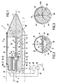
fig. 1 est une coupe-élévation de l'applicateur conforme à l'invention. - Les
fig. 2 et 3 sont des coupes transversales prises selon les lignes II-II et III-III de lafig. 1 . - La
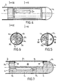
fig. 4 est une vue de dessus, partie en coupe, d'un autre exemple de réalisation de l'applicateur. - Les
fig. 5 et 6 sont des coupes transversales prises selon les lignes V-V et VI-VI de lafig. 4 . - La
fig. 7 est une coupe prise selon la ligne brisée VII-VII de lafig. 5 . - Selon les
fig. 1 à 3 , l'applicateur ultrasonore intratissulaire comprend une tête d'application 1 qui est, de préférence mais non exclusivement, réalisée en une matière non ferromagnétique, de manière à pouvoir être mise en oeuvre en complémentarité d'installations de traitement ou de contrôle parallèles telles que celle faisant intervenir le principe de la résonnance magnétique nucléaire. - La tête 1 est portée par un élément tubulaire 2 qui est ici constitué par un élément rigide adapté de toute façon appropriée étanche sur la partie 3 de la tête 1, considérée comme arrière par rapport à un embout avant 4, dit de pénétration. Il doit être considéré que l'élément tubulaire 2 pourrait être entièrement constitué, ou pour partie complété, par une gaine à caractère souple, pour faciliter un cheminement contrôlé, endoscopique ou endocanalaire. A titre d'exemple, une telle gaine pourrait être constituée avantageusement par une succession d'enroulements co-axiaux filaires en spires contiguës à partir d'un fil de section circulaire ou polygonale.
- La tête 1 comprend un corps 5 formant les parties arrière 3 et avant 4 entre lesquelles il présente un chambrage 6 qui est au moins ouvert sur une partie de la périphérie du corps 5. Dans l'exemple d'application illustré, le corps 5 est de forme générale préférentiellement cylindrique et la partie 4 présente alors avantageusement une forme ogivale, tronc-pyramidale ou conique, bien qu'une forme sphérique ou semi-sphérique puisse aussi être retenue.
- Le chambrage 6 est réalisé pour délimiter, sensiblement au milieu de sa profondeur dans l'exemple représenté, un épaulement ou siège 7 sur lequel peut être monté, adapté, immobilisé avec étanchéité, un transducteur ultrasonore plan 8, de forme générale rectangulaire dont la longueur est orientée dans le sens de l'axe longitudinal x-x', du corps 5 et, plus particulièrement, dans l'exemple illustré, parallèlement à cet axe.
- Le transducteur ultrasonore 8 est relié par des connexions de surface 9 et 10 à deux fils d'alimentation 11 et 12, qui sont engagés à travers la partie arrière 3 par l'intermédiaire d'un perçage 13 traversant s'ouvrant dans le chambrage 6. Les fils d'alimentation 11 et 12 sont raccordés à une source électrique non représentée, capable d'appliquer au transducteur des fréquences de l'ordre de 5 à 10 MHz. Le transducteur 8 peut alors être alimenté par un signal électrique monofréquence ou multifréquences selon la nature de l'émission ultrasonore souhaitée.
- Le montage étanche du transducteur 8 sur l'épaulement 7 et la position de ce dernier par rapport au fond 14 du chambrage 6 sont définis de manière qu'après adaptation du transducteur, celui-ci délimite avec le fond 14 une chambre 15 qui est remplie d'air de manière à constituer un moyen de non-propagation ultrasonore à partir de la grande face 16 arrière du transducteur 8.
- Il en résulte l'existence d'une face d'émission privilégiée plane constituée par la grande face avant 17 qui est celle orientée vers l'ouverture du chambrage 6 par rapport à la périphérie du corps 5. De manière préférée, la face d'émission plane présente des dimensions suffisantes pour émettre, lors du fonctionnement du transducteur, des ondes ultrasonores sensiblement planes qui ne divergent pas au voisinage du transducteur et de l'applicateur.
- Le transducteur ultrasonore 8 est associé à des moyens d'appréciation de sa montée en température. De tels moyens sont, dans l'exemple illustré, constitués par un thermocouple 18 qui traverse de façon étanche la partie arrière 3 de la tête 1 pour être raccordé à un témoin visuel 19, tel qu'un indicateur de température. Le thermocouple 18 est de préférence aussi, couplé à un dispositif régulateur 20 dont la fonction apparaît dans ce qui suit. Il pourrait être retenu de remplacer le thermocouple 18 par un moyen équivalent par exemple, un moyen de mesure de la variation de la capacité électrique du transducteur ultrasonore en fonction de sa température.
- Le chambrage 6 est fermé dans sa partie s'ouvrant à la périphérie du corps 5 par l'intermédiaire d'une membrane 21 constituée par une feuille en une matière ne faisant intervenir qu'un faible coefficient d'atténuation ultrasonique. Avantageusement, cette membrane 21 est constituée par une feuille en polyéthylène basse pression d'une épaisseur de 12 µm rapportée sur le corps 5 par l'intermédiaire d'une colle appropriée telle qu'une colle du type cyanocrylate.
- La membrane 21 peut être constituée par un segment tubulaire entourant complètement le corps 5 ou par un segment sectoriel couvrant l'ouverture du chambrage 6.
- La présence de la membrane 21 permet de délimiter dans le chambrage 6, avec la face 17 du transducteur 8, une cavité 22 fermée de façon étanche et qui est en communication, d'une part, avec un trou 23 pratiqué dans la partie 4 au niveau de la surface extérieure de laquelle il s'ouvre et, d'autre part, avec un conduit 24 dit d'amenée, traversant la partie arrière 3. Le conduit 24 est raccordé à un élément tubulaire 25 faisant partie d'un circuit de circulation d'un fluide de refroidissement fourni par une pompe 26 à partir d'une réserve 27. Le fluide de refroidissement peut être de différente nature, tout en étant choisi de manière à remplir une fonction de couplage ultrasonore entre le transducteur 8 et la membrane 21 en occupant toujours complètement la cavité 22. A titre d'exemple préférentiel, un tel fluide est constitué par de l'eau dégazée.
- Le fonctionnement de la pompe 26, au moins pour ce qui concerne le débit fourni, est placé sous la dépendance du régulateur 20 appréciant la montée en température du transducteur ultrasonore 8.
- Le circuit de circulation de fluide pourrait faire intervenir, outre le circuit aller 25, un circuit de retour 28 dit aussi "de reprise", ménagé dans la partie avant 4, à la place du trou d'évacuation 23. Un tel circuit de reprise pourrait alors être raccordé directement à la source 27.
- En règle générale, la partie de l'élément tubulaire 2 faisant suite à la partie arrière 3 du corps de tête 1 est remplie d'une matière d'occupation, d'étanchéification et de comblement visant à isoler, contenir, maintenir, confiner et protéger les lignes d'asservissement qui sont constituées par les fils d'alimentation 11 et 12, par le thermocouple 18 et par le ou les circuits 25.
- L'applicateur décrit ci-dessus peut être introduit en raison de sa forme même à proximité, voire dans une tumeur à traiter, par voie interne, i.e. par voie endoscopique ou intracanalaire, de façon à appliquer, au sein de cette zone, une montée en température qui est créée par l'absorption des ultrasons dans le milieu absorbant ou les tissus, situés en regard de la face d'émission, après le raccordement du transducteur 8 à la source électrique.
- En raison de la présence du coussin d'air occupant la chambre 15, le fonctionnement du transducteur 8 se traduit par une émission ultrasonore uniquement à partir de la face d'émission 17 qui produit un champ proche, non divergent, traversant la cavité 22 et la membrane 21 selon une direction de propagation normale au plan de la face d'émission 17. La montée en température du transducteur ultrasonore 8, due au fait que son rendement électro-acoustique est inférieur à 1, est appréciée par l'intermédiaire du moyen 18 qui fournit une information au régulateur 20 permettant de contrôler les conditions de fonctionnement de la pompe 26 pour fournir, à l'intérieur de la cavité 22 toujours pleine, un débit de fluide de refroidissement convenable, évacué par le trou 23 par perfusion naturelle dans les tissus ou par reprise par le conduit 28.
- De cette manière, il est possible d'émettre un champ puissant sans provoquer une montée en température locale élevée qui pourrait autrement être de nature à produire ou provoquer une rupture de la membrane par échauffement et/ou la génération de microbulles d'ébullition entre la membrane 21 et le tissu et qui auraient pour effet d'interrompre la propagation des ultrasons avec pour conséquence la destruction du transducteur ultrasonore.
- L'émission d'un champ proche de direction privilégiée sensiblement perpendiculaire à la face d'émission, comme l'indique la flèche F, permet d'engager un traitement sélectif, précis et localisé d'une tumeur par approche centralisée ou à distance, laquelle tumeur peut toutefois être aussi traitée de façon plus complète par application volumique de chaleur en soumettant le transducteur 8 à une rotation sur une plage angulaire sectorielle ou totale. A cette fin, l'applicateur selon l'invention comporte des moyens pour déplacer en rotation le transducteur. Selon l'exemple illustré, ces moyens de rotation sont constitués par l'élément tubulaire 2 qui permet l'entraînement en rotation de la tête d'application 1 sur son axe x-x' et, par suite, la rotation du transducteur 8. De manière préférée, l'élément tubulaire 2 présente un coefficient de résistance à la torsion élevé pour permettre un entraînement en rotation convenable de la tête d'application.
- Les moyens pour déplacer en rotation le transducteur pourraient également être constitués par des moyens moteurs ou de transmission permettant d'assurer une rotation du transducteur seul, sans déplacement conjoint de la tête d'application. De manière préférée mais non exclusive, la rotation du transducteur est effectuée autour d'un axe parallèle à un grand axe de la face d'émission. Par ailleurs, il doit être noté que la rotation du transducteur peut être continue pendant la durée d'émission en étant alternée ou non, mais également séquentielle en faisant intervenir une rotation pas à pas du transducteur, de manière à chauffer successivement des zones contiguës.
- Il peut aussi être procédé à un déplacement alternatif ou non, rectiligne et d'amplitude variable sur l'axe x-x' de la tête 1 pour produire une nécrose d'un volume plus important de tissu. Un tel déplacement en translation de la tête peut également être combiné à un mouvement de rotation du transducteur.
- Ainsi, par les moyens selon l'invention de contrôle et de régulation de température à partir de la face d'émission 17 du transducteur 8 et en raison de l'émission d'un champ proche directionnel selon la flèche F, il devient possible de procéder au traitement par hyperthermie localisée de tumeurs de faible volume ou non, à distance plus ou moins importante de la tête 1 et de conduire, par ce moyen, des traitements de tumeurs qui seraient ordinairement considérées, par leur localisation spécifique, inaccessibles à toute possibilité d'application hyperthermique localisée.
- En adoptant un transducteur de 10 mm sur 3 mm et d'épaisseur λ/2, λ étant la longueur d'onde, réalisé en PZT 462 et susceptible de fonctionner sous des fréquences de 3 à 20 MHz, il est possible de réaliser un applicateur d'un diamètre extérieur voisin de 3,6 mm en faisant intervenir des circuits 25 de diamètre égal à 0,8 mm susceptibles d'entretenir une circulation de fluide de refroidissement dans la cavité 22 à raison de 7 ml/min.
- De tels moyens sont favorables à une application de température élevée pendant des durées courtes qui sont néanmoins suffisantes pour atteindre une nécrose de coagulation.
- En effet, la mise en oeuvre d'un transducteur présentant une face d'émission plane permet la production d'ondes ultrasonores sensiblement planes qui assurent une diffusion homogène et profonde de l'énergie acoustique dans le milieu absorbant.
- De plus, compte tenu de la nature plane des ondes émises par un transducteur plan, ce dernier offre un rendement puissance acoustique émise par rapport à la puissance fournie au transducteur supérieure à celui offert par un transducteur cylindrique selon l'art antérieur.
- Ainsi, dans le cadre d'un essai in vivo sur un foie de porc, un applicateur conforme à l'invention, mettant en oeuvre un transducteur plan de dimension 10 mm x 3 mm alimenté par un signal électrique d'une fréquence de 10 MHz, de manière à rayonner au niveau de sa surface d'émission, une puissance de 14 Watts/cm2, permet d'obtenir après une durée d'émission de 20 secondes, une lésion en regard de la face émettrice présentant une profondeur de 10 à 12 mm.
- En revanche, dans le cadre d'un essai in vivo identique, un applicateur présentant des dimensions externes identiques à celles du précédent mais mettant en oeuvre un transducteur cylindrique selon l'art antérieur de diamètre externe 3 mm et de longueur 10 mm, alimenté par un signal électrique d'une fréquence de 10 MHz, de manière à rayonner au niveau de sa surface d'émission une puissance de 14 Watts/cm2, permet d'obtenir, après une durée d'émission de 20 secondes, une lésion, en regard de la face d'émission cylindrique du transducteur, présentant une profondeur de 2 à 3 mm seulement.
- Il apparaît donc que toute chose étant égale par ailleurs, la mise en oeuvre d'un transducteur plan selon l'invention permet avantageusement d'augmenter la profondeur de lésion d'un facteur 3,33 à 6 par rapport à un transducteur cylindrique.
- De même, en utilisant un applicateur selon l'invention, tel que celui décrit ci-dessus mis en oeuvre dans les mêmes conditions d'alimentation électrique et de puissance, il est possible en déplaçant en rotation la tête d'application autour de son axe, d'engendrer, avec une durée d'émission de 7 à 8 mn, une lésion cylindrique présentant un diamètre extérieur de 10 à 12 mm.
- Or, un applicateur selon l'art antérieur avec un transducteur cylindrique, tel que celui décrit ci-dessus, ne permet d'obtenir une lésion cylindrique présentant un diamètre extérieur de 10 à 12 mm qu'avec une durée d'émission de 18 à 20 mn.
- Il apparaît clairement que la mise en oeuvre d'un transducteur plan selon l'invention permet avantageusement, toute chose étant égale par ailleurs, une réduction de la durée d'émission et donc de chauffage d'un facteur 1,5 à 2 par rapport à un transducteur cylindrique.
- Les caractéristiques constructives et fonctionnelles ouvrent largement la possibilité d'utiliser l'applicateur par voie interne, soit par voie endoscopique, soit encore par voie intra-canalaire en constituant, pour partie au moins, l'élément 2 sous la forme d'une gaine souple, soit encore par application percutanée à partir d'un élément 2 tubulaire rigide.
- Pour faciliter le cheminement intra-canalaire ou à l'intérieur d'un guide opérateur endoscopique, il est avantageusement prévu de ménager dans le corps 5 une rainure ou un passage 30 permettant l'engagement d'un fil guide 31 favorisant l'évolution intra-canalaire de la tête 1, notamment lorsque le canal investi est de section relativement faible et connaît des variations d'orientation à faible rayon de courbure. Il est également avantageusement prévu de lier le corps 5 par sa partie arrière 3 à un élément filaire de traction 32 dont la fonction est de permettre, notamment lorsque la gaine 2 est constituée sous la forme d'un enroulement filaire hélicoïdal, d'exercer sur l'applicateur un effort de traction pour favoriser son extraction de l'intérieur du canal ou du guide opérateur endoscopique investi.
- Les
fig. 4 à 7 montrent une forme préférée de réalisation industrielle de la tête 1 qui comporte un corps 51 inséré dans un élément tubulaire 21 dont la longueur au-delà de la partie arrière 31 , est appropriée pour une fonction typiquement endoscopique ou une fonction endocanalaire par association avec une gaine souple déformable abritant comme dans l'exemple précédent les lignes d'établissement fonctionnel à distance de la tête 1. - Dans un tel cas, bien que cela ne soit pas représenté, l'élément tubulaire 21 comporte une fenêtre ménagée en correspondance du chambrage 61 , une telle fenêtre étant fermée comme dans l'exemple précédent par une membrane 211 .
- Dans l'exemple de réalisation selon les
fig. 4 à 7 les mêmes éléments constitutifs que ceux de l'exemple précédent sont désignés par les mêmes références affectées de l'indice1. Dans cette forme de réalisation, il est avantageux de ménager, à partir de la périphérie du corps 5 des encoches ou rainures 35 et 36 réservées au passage des fils 11 et 12 en remplacement du perçage 13. - Dans les exemples de réalisation ci-dessus il est considéré que la tête 1 est équipée d'un transducteur 8 dont la position est de préférence parallèle par l'une de ses grandes faces à l'axe longitudinal du corps 51 .
- Il doit être considéré que la tête peut être équipée de plusieurs transducteurs 8 qui répondent à une semblable caractéristique en étant montés de même manière pour occuper toute ou partie de la périphérie du corps 5 en étant situés pour chacun d'eux en retrait de cette périphérie afin de ménager pour la face d'émission 17 une cavité de couplage par l'intermédiaire du fluide de refroidissement. Dans un tel cas, il doit aussi être retenu que chaque transducteur est associé à des moyens de non ou de faible propagation ultrasonique placés en relation avec la face arrière 16 afin de favoriser la seule émission d'un champ proche utile à partir de la face 17.
- Il peut donc être envisagé de faire comporter à la tête 1, par exemple deux ou trois transducteurs.
- Selon l'invention, il est également possible d'envisager de disposer un ou plusieurs transducteurs 8 pour qu'ils s'étendent de façon non parallèle à l'axe x-x' en présentant une inclinaison relativement à cet axe pour que le champ proche émis adopte une direction non normale à cet axe.
- Il doit aussi être retenu que la sonde peut être pourvue d'au moins un transducteur 8 qui serait disposé perpendiculairement à l'axe x-x', en étant situé au voisinage de la partie avant 4. Dans un tel cas, la membrane 21 pourrait alors être réalisée sous la forme d'un ballon entourant à distance le transducteur pour délimiter un volume de protection et de confinement d'un liquide de refroidissement et de couplage ultrasonore.
- La
fig. 7 met en évidence qu'il peut être avantageux de faire comporter au corps 5, par exemple au niveau du chambrage 6, des repères radio-opaques 40 permettant d'assumer une fonction de repérage fluoroscopique lors d'un cheminement endoscopique ou endocanalaire. - Dans les exemples ci-dessus, l'applicateur comprend, de manière préférée, des moyens pour refroidir le transducteur. Toutefois, l'applicateur pourrait également ne pas comporter de tels moyens de refroidissement.
- L'utilisation de l'applicateur a été décrite en relation avec un traitement médical. Toutefois, l'applicateur pourrait être utilisé dans toute application industrielle pour laquelle il est nécessaire de chauffer localement, un milieu absorbant les ondes ultrasonores, dans une région située en profondeur par rapport à la surface extérieure de l'objet à traiter.
- Par exemple, pour assurer la destruction par la chaleur d'un foyer parasitaire au sein d'un volume de bois ou d'un arbre dont la destruction n'est pas souhaitable, un procédé de chauffage conforme à l'invention consiste à percer un canal de faible diamètre pour le passage de l'applicateur, jusqu'au foyer. Un tel canal constitue, bien entendu, une voie interne artificielle pour la mise en place de l'applicateur.
- Une fois l'applicateur conforme à l'invention placé en position, le transducteur est alimenté en courant électrique, d'une fréquence donnée, pendant une durée prédéterminée en fonction de la nature du foyer parasitaire et de l'étendue de ce dernier. Bien entendu, le transducteur peut être alimenté par un courant multifréquences.
- Selon le volume du foyer parasitaire, le transducteur peut être déplacé en rotation pour chauffer une région angulaire plus étendue. Cette rotation peut être continue, en étant alternée ou non, pendant toute la durée du traitement, ou encore séquentielle pas à pas, de manière à chauffer successivement des zones contigües de la région à traiter.
- Le procédé de chauffage pourrait également être utilisé pour le chauffage de résine thermodurcissable injectée en profondeur d'une pièce de bois à considérer dans le cadre, par exemple, de sa restauration.
- L'invention n'est pas limitée aux exemples décrits et représentés car diverses modifications peuvent y être apportées sans sortir de son cadre.
Claims (20)
- - Applicateur ultrasonore pour le chauffage, par voie interne, d'un milieu absorbant les ultrasons, comprenant:- une tête d'application (1) comportant au moins un transducteur ultrasonore plan (8) dont une face (17), dite d'émission, est recouverte à distance d'une membrane (21) étanche et transparente aux ultrasons, et dont une autre face, opposée à la face d'émission, est associée à des moyens (15) de non ou de faible propagation ultrasonore, la face d'émission étant plane pour émettre des ondes ultrasonores sensiblement planes non divergentes traversant la membrane selon une direction de propagation sensiblement normale à la face d'émission,- des moyens (11, 12) pour relier à distance le transducteur à un générateur électrique,- et des moyens (22, 23, 24) pour réaliser un couplage ultrasonore avec la membrane,caractérisé en ce que :- le transducteur ultrasonore (8) est immobilisé avec étanchéité sur un épaulement ou siège (7) délimité dans un chambrage (6) formé dans la tête d'application et ouvert sur une partie au moins de sa périphérie de manière à délimiter avec le fond (14) du chambrage (6) une chambre (15) remplie d'air constituant le moyen de non ou de faible propagation ultrasonore à partir de la face (16) opposée à la face d'émission du transducteur (8),et en ce qu'il comporte des moyens de contrôle (18) et de régulation (20) de la température de la face d'émission (17) coopérant avec un circuit de circulation (23, 24, 25, 26, 27) d'un fluide de refroidissement sur la surface d'émission (17) du transducteur.
- - Applicateur selon la revendication 1, caractérisé en ce qu'il comporte des moyens pour déplacer en rotation le transducteur plan.
- - Applicateur selon la revendication 1 ou 2, caractérisé en ce qu'il comprend des moyens pour refroidir le transducteur.
- - Applicateur selon l'une des revendications 1 à 3, caractérisé en ce qu'il comprend un élément tubulaire (2) portant ladite tête à une extrémité et abritant les lignes (25, 11, 12, 18) d'établissement fonctionnel à distance de la tête.
- - Applicateur selon l'une des revendications 1 à 4, caractérisé en ce que la tête comporte au moins un transducteur ultrasonore plan dont la plus grande dimension est orientée dans le sens de l'axe longitudinal (x-x') de la tête.
- - Applicateur selon la revendication 5, caractérisé en ce que la tête comporte au moins un transducteur ultrasonore plan dont la face d'émission est parallèle à l'axe longitudinal de la tête.
- - Applicateur selon la revendication 5, caractérisé en ce que la tête comporte au moins un transducteur ultrasonore plan dont la face d'émission fait un angle avec l'axe longitudinal de la tête.
- - Applicateur selon l'une des revendications 1 à 4, caractérisé en ce que la tête comporte au moins un transducteur ultrasonore plan dont la face d'émission est sensiblement normale à l'axe de la tête.
- - Applicateur selon l'une des revendications 1 à 6 caractérisé en que la tête est réalisée en un matériau non ferro-magnétique.
- - Applicateur selon l'une des revendications 1 à 9, caractérisé en que la tête comporte une membrane protectrice (21) réalisée sous la forme d'une enveloppe au moins partielle fermant une cavité d'application (22) présentée par la tête et dans laquelle est disposée le transducteur plan (8).
- - Applicateur selon l'une des revendications 1 à 9, caractérisé en ce que la tête comporte une membrane protectrice réalisée sous la forme d'un ballon fermant une cavité d'application présentée par la tête et dans laquelle est disposé le transducteur plan.
- - Applicateur selon la revendication 1, caractérisé en ce que le circuit de circulation de fluide de refroidissement comporte un conduit (24) raccordé à une ligne (25) d'amenée d'un fluide de refroidissement circulant sur la face d'émission du transducteur et occupant tout le volume délimité par la cavité (22).
- - Applicateur selon la revendication 12, caractérisé en ce que la tête comporte un trou (23) d'évacuation vers l'extérieur du fluide de refroidissement.
- - Applicateur selon la revendication 12, caractérisé en ce que la tête comporte un second conduit (28) dit de reprise raccordé à une ligne de retour du fluide de refroidissement.
- - Applicateur selon la revendication 12, caractérisé en ce que les moyens de contrôle et de régulation de la température de la surface d'émission (17) du transducteur comportent des moyens (18) de mesure de la température du transducteur ainsi qu'à des moyens (20) de régulation de cette température.
- - Applicateur selon l'une quelconque des revendications 1 à 15, caractérisé en ce que la tête comporte un conduit ou passage traversant (31), sensiblement parallèle à l'axe longitudinal de la tête et réservé à l'engagement d'un guide filaire de cheminement endocanalaire.
- - Applicateur selon l'une quelconque des revendications 1 à 16, caractérisé en ce que la tête est raccordée à un élément filaire de traction (32).
- - Applicateur selon l'une quelconque des revendications 1 à 17, caractérisée en ce que la tête est portée en bout d'un élément tubulaire constitué par une gaine souple.
- - Applicateur selon l'une des revendications 1 à 18, caractérisé en ce que la tête porte au moins un repère radio opaque (40) assumant une fonction de repérage fluoroscopique.
- - Applicateur selon la revendication 2, caractérisé en ce que la tête d'application possède une forme sensiblement cylindrique et que les moyens pour déplacer en rotation le transducteur sont constitués sous la forme sensiblement cylindrique de la tête d'application.
Applications Claiming Priority (3)
| Application Number | Priority Date | Filing Date | Title |
|---|---|---|---|
| FR9707529A FR2764516B1 (fr) | 1997-06-11 | 1997-06-11 | Applicateur intratissulaire ultrasonore pour l'hyperthermie |
| FR9707529 | 1997-06-11 | ||
| PCT/FR1998/001212 WO1998056462A1 (fr) | 1997-06-11 | 1998-06-11 | Applicateur intratissulaire ultrasonore pour l'hyperthermie |
Publications (2)
| Publication Number | Publication Date |
|---|---|
| EP0988092A1 EP0988092A1 (fr) | 2000-03-29 |
| EP0988092B1 true EP0988092B1 (fr) | 2008-06-11 |
Family
ID=9508095
Family Applications (1)
| Application Number | Title | Priority Date | Filing Date |
|---|---|---|---|
| EP98930828A Expired - Lifetime EP0988092B1 (fr) | 1997-06-11 | 1998-06-11 | Applicateur intratissulaire ultrasonore pour l'hyperthermie |
Country Status (8)
| Country | Link |
|---|---|
| US (1) | US6379320B1 (fr) |
| EP (1) | EP0988092B1 (fr) |
| JP (1) | JP2002503128A (fr) |
| AT (1) | ATE397957T1 (fr) |
| CA (1) | CA2293544C (fr) |
| DE (1) | DE69839606D1 (fr) |
| FR (1) | FR2764516B1 (fr) |
| WO (1) | WO1998056462A1 (fr) |
Families Citing this family (224)
| Publication number | Priority date | Publication date | Assignee | Title |
|---|---|---|---|---|
| US6723063B1 (en) * | 1998-06-29 | 2004-04-20 | Ekos Corporation | Sheath for use with an ultrasound element |
| US6589174B1 (en) | 2000-10-20 | 2003-07-08 | Sunnybrook & Women's College Health Sciences Centre | Technique and apparatus for ultrasound therapy |
| US20030092988A1 (en) | 2001-05-29 | 2003-05-15 | Makin Inder Raj S. | Staging medical treatment using ultrasound |
| US7846096B2 (en) | 2001-05-29 | 2010-12-07 | Ethicon Endo-Surgery, Inc. | Method for monitoring of medical treatment using pulse-echo ultrasound |
| US11229472B2 (en) | 2001-06-12 | 2022-01-25 | Cilag Gmbh International | Modular battery powered handheld surgical instrument with multiple magnetic position sensors |
| US20040019318A1 (en) * | 2001-11-07 | 2004-01-29 | Wilson Richard R. | Ultrasound assembly for use with a catheter |
| DE60213457T2 (de) * | 2001-12-03 | 2007-10-18 | Ekos Corp., Bothell | Ultraschallkatheter für kleine gefässe |
| ATE520362T1 (de) | 2001-12-03 | 2011-09-15 | Ekos Corp | Katheter mit mehreren ultraschall-abstrahlenden teilen |
| SE520857C2 (sv) * | 2002-01-15 | 2003-09-02 | Ultrazonix Dnt Ab | Anordning med såväl terapeutiska som diagnostiska givare för mini-invasiv ultraljudsbehandling av ett objekt, där den terapeuti ska givaren är termiskt isolerad |
| AU2003212481A1 (en) * | 2002-02-28 | 2003-09-09 | Ekos Corporation | Ultrasound assembly for use with a catheter |
| US20050080359A1 (en) * | 2002-12-16 | 2005-04-14 | Chunliang Zhao | Ultrasonic treatment device |
| EP1583569A4 (fr) * | 2003-01-03 | 2009-05-06 | Ekos Corp | Catheter a ultrasons comprenant un champ d'energie axial |
| FR2849781B1 (fr) * | 2003-01-14 | 2005-03-25 | Edap S A | Sonde de therapie |
| EP1619995A2 (fr) * | 2003-04-22 | 2006-02-01 | Ekos Corporation | Catheter veineux central ultrasonore perfectionne |
| SE526718C2 (sv) * | 2003-06-04 | 2005-10-25 | Ultrazonix Dnt Ab | Ultraljudssond med en central öppning |
| JP3999715B2 (ja) * | 2003-08-28 | 2007-10-31 | オリンパス株式会社 | 超音波処置装置 |
| CA2551831A1 (fr) * | 2004-01-29 | 2005-08-11 | Ekos Corporation | Catheter ultrasonore pour petits vaisseaux |
| US20050209578A1 (en) * | 2004-01-29 | 2005-09-22 | Christian Evans Edward A | Ultrasonic catheter with segmented fluid delivery |
| US8182501B2 (en) | 2004-02-27 | 2012-05-22 | Ethicon Endo-Surgery, Inc. | Ultrasonic surgical shears and method for sealing a blood vessel using same |
| US20050228286A1 (en) * | 2004-04-07 | 2005-10-13 | Messerly Jeffrey D | Medical system having a rotatable ultrasound source and a piercing tip |
| US20050240105A1 (en) * | 2004-04-14 | 2005-10-27 | Mast T D | Method for reducing electronic artifacts in ultrasound imaging |
| US20050240124A1 (en) * | 2004-04-15 | 2005-10-27 | Mast T D | Ultrasound medical treatment system and method |
| US20050234438A1 (en) * | 2004-04-15 | 2005-10-20 | Mast T D | Ultrasound medical treatment system and method |
| US7494467B2 (en) * | 2004-04-16 | 2009-02-24 | Ethicon Endo-Surgery, Inc. | Medical system having multiple ultrasound transducers or an ultrasound transducer and an RF electrode |
| US20050256405A1 (en) * | 2004-05-17 | 2005-11-17 | Makin Inder Raj S | Ultrasound-based procedure for uterine medical treatment |
| US7883468B2 (en) * | 2004-05-18 | 2011-02-08 | Ethicon Endo-Surgery, Inc. | Medical system having an ultrasound source and an acoustic coupling medium |
| US20050261587A1 (en) * | 2004-05-20 | 2005-11-24 | Makin Inder R S | Ultrasound medical system and method |
| US7951095B2 (en) * | 2004-05-20 | 2011-05-31 | Ethicon Endo-Surgery, Inc. | Ultrasound medical system |
| US7695436B2 (en) * | 2004-05-21 | 2010-04-13 | Ethicon Endo-Surgery, Inc. | Transmit apodization of an ultrasound transducer array |
| US20050261588A1 (en) * | 2004-05-21 | 2005-11-24 | Makin Inder Raj S | Ultrasound medical system |
| US7473250B2 (en) * | 2004-05-21 | 2009-01-06 | Ethicon Endo-Surgery, Inc. | Ultrasound medical system and method |
| US7806839B2 (en) | 2004-06-14 | 2010-10-05 | Ethicon Endo-Surgery, Inc. | System and method for ultrasound therapy using grating lobes |
| EP3162309B1 (fr) | 2004-10-08 | 2022-10-26 | Ethicon LLC | Instrument chirurgical ultrasonique |
| US20060089626A1 (en) * | 2004-10-22 | 2006-04-27 | Vlegele James W | Surgical device guide for use with an imaging system |
| US7833221B2 (en) * | 2004-10-22 | 2010-11-16 | Ethicon Endo-Surgery, Inc. | System and method for treatment of tissue using the tissue as a fiducial |
| US7452357B2 (en) * | 2004-10-22 | 2008-11-18 | Ethicon Endo-Surgery, Inc. | System and method for planning treatment of tissue |
| US7771418B2 (en) * | 2005-03-09 | 2010-08-10 | Sunnybrook Health Sciences Centre | Treatment of diseased tissue using controlled ultrasonic heating |
| US8801701B2 (en) * | 2005-03-09 | 2014-08-12 | Sunnybrook Health Sciences Centre | Method and apparatus for obtaining quantitative temperature measurements in prostate and other tissue undergoing thermal therapy treatment |
| US20070016184A1 (en) * | 2005-07-14 | 2007-01-18 | Ethicon Endo-Surgery, Inc. | Medical-treatment electrode assembly and method for medical treatment |
| US20070038115A1 (en) * | 2005-08-12 | 2007-02-15 | Quigley David P | High intensity ultrasound apparatus methods and systems |
| US20070191713A1 (en) | 2005-10-14 | 2007-08-16 | Eichmann Stephen E | Ultrasonic device for cutting and coagulating |
| US20070167825A1 (en) * | 2005-11-30 | 2007-07-19 | Warren Lee | Apparatus for catheter tips, including mechanically scanning ultrasound probe catheter tip |
| US20070167824A1 (en) * | 2005-11-30 | 2007-07-19 | Warren Lee | Method of manufacture of catheter tips, including mechanically scanning ultrasound probe catheter tip, and apparatus made by the method |
| US7621930B2 (en) | 2006-01-20 | 2009-11-24 | Ethicon Endo-Surgery, Inc. | Ultrasound medical instrument having a medical ultrasonic blade |
| US8192363B2 (en) * | 2006-10-27 | 2012-06-05 | Ekos Corporation | Catheter with multiple ultrasound radiating members |
| US10182833B2 (en) | 2007-01-08 | 2019-01-22 | Ekos Corporation | Power parameters for ultrasonic catheter |
| US20080234709A1 (en) | 2007-03-22 | 2008-09-25 | Houser Kevin L | Ultrasonic surgical instrument and cartilage and bone shaping blades therefor |
| US8226675B2 (en) | 2007-03-22 | 2012-07-24 | Ethicon Endo-Surgery, Inc. | Surgical instruments |
| US8142461B2 (en) | 2007-03-22 | 2012-03-27 | Ethicon Endo-Surgery, Inc. | Surgical instruments |
| US8911460B2 (en) | 2007-03-22 | 2014-12-16 | Ethicon Endo-Surgery, Inc. | Ultrasonic surgical instruments |
| US8057498B2 (en) | 2007-11-30 | 2011-11-15 | Ethicon Endo-Surgery, Inc. | Ultrasonic surgical instrument blades |
| EP2494932B1 (fr) | 2007-06-22 | 2020-05-20 | Ekos Corporation | Appareil pour le traitement des hémorragies intracrâniennes |
| US8808319B2 (en) | 2007-07-27 | 2014-08-19 | Ethicon Endo-Surgery, Inc. | Surgical instruments |
| US8882791B2 (en) | 2007-07-27 | 2014-11-11 | Ethicon Endo-Surgery, Inc. | Ultrasonic surgical instruments |
| US8523889B2 (en) | 2007-07-27 | 2013-09-03 | Ethicon Endo-Surgery, Inc. | Ultrasonic end effectors with increased active length |
| US8348967B2 (en) | 2007-07-27 | 2013-01-08 | Ethicon Endo-Surgery, Inc. | Ultrasonic surgical instruments |
| US8257377B2 (en) * | 2007-07-27 | 2012-09-04 | Ethicon Endo-Surgery, Inc. | Multiple end effectors ultrasonic surgical instruments |
| US9044261B2 (en) * | 2007-07-31 | 2015-06-02 | Ethicon Endo-Surgery, Inc. | Temperature controlled ultrasonic surgical instruments |
| US8252012B2 (en) | 2007-07-31 | 2012-08-28 | Ethicon Endo-Surgery, Inc. | Ultrasonic surgical instrument with modulator |
| US8512365B2 (en) | 2007-07-31 | 2013-08-20 | Ethicon Endo-Surgery, Inc. | Surgical instruments |
| US8430898B2 (en) | 2007-07-31 | 2013-04-30 | Ethicon Endo-Surgery, Inc. | Ultrasonic surgical instruments |
| EP2796102B1 (fr) | 2007-10-05 | 2018-03-14 | Ethicon LLC | Instruments chirurgicaux ergonomiques |
| US7901423B2 (en) | 2007-11-30 | 2011-03-08 | Ethicon Endo-Surgery, Inc. | Folded ultrasonic end effectors with increased active length |
| US10010339B2 (en) | 2007-11-30 | 2018-07-03 | Ethicon Llc | Ultrasonic surgical blades |
| CN105148416B (zh) * | 2008-04-09 | 2019-01-29 | 朱利安·伊特兹科维特兹 | 包括经皮探针的医疗系统 |
| US8095327B2 (en) * | 2008-04-15 | 2012-01-10 | Olympus Medical Systems Corp. | Power supply apparatus for operation |
| US9089360B2 (en) | 2008-08-06 | 2015-07-28 | Ethicon Endo-Surgery, Inc. | Devices and techniques for cutting and coagulating tissue |
| US8058771B2 (en) * | 2008-08-06 | 2011-11-15 | Ethicon Endo-Surgery, Inc. | Ultrasonic device for cutting and coagulating with stepped output |
| RU2526265C2 (ru) * | 2009-03-02 | 2014-08-20 | Конинклейке Филипс Электроникс, Н.В. | Трансуретральный ультразвуковой датчик для лечения предстательной железы |
| US20100298743A1 (en) * | 2009-05-20 | 2010-11-25 | Ethicon Endo-Surgery, Inc. | Thermally-activated coupling arrangements and methods for attaching tools to ultrasonic surgical instruments |
| US9700339B2 (en) | 2009-05-20 | 2017-07-11 | Ethicon Endo-Surgery, Inc. | Coupling arrangements and methods for attaching tools to ultrasonic surgical instruments |
| US8319400B2 (en) | 2009-06-24 | 2012-11-27 | Ethicon Endo-Surgery, Inc. | Ultrasonic surgical instruments |
| US8663220B2 (en) | 2009-07-15 | 2014-03-04 | Ethicon Endo-Surgery, Inc. | Ultrasonic surgical instruments |
| US9017326B2 (en) | 2009-07-15 | 2015-04-28 | Ethicon Endo-Surgery, Inc. | Impedance monitoring apparatus, system, and method for ultrasonic surgical instruments |
| US8461744B2 (en) | 2009-07-15 | 2013-06-11 | Ethicon Endo-Surgery, Inc. | Rotating transducer mount for ultrasonic surgical instruments |
| US11090104B2 (en) | 2009-10-09 | 2021-08-17 | Cilag Gmbh International | Surgical generator for ultrasonic and electrosurgical devices |
| USRE47996E1 (en) | 2009-10-09 | 2020-05-19 | Ethicon Llc | Surgical generator for ultrasonic and electrosurgical devices |
| US9168054B2 (en) | 2009-10-09 | 2015-10-27 | Ethicon Endo-Surgery, Inc. | Surgical generator for ultrasonic and electrosurgical devices |
| US9050093B2 (en) | 2009-10-09 | 2015-06-09 | Ethicon Endo-Surgery, Inc. | Surgical generator for ultrasonic and electrosurgical devices |
| US10172669B2 (en) | 2009-10-09 | 2019-01-08 | Ethicon Llc | Surgical instrument comprising an energy trigger lockout |
| US10441345B2 (en) | 2009-10-09 | 2019-10-15 | Ethicon Llc | Surgical generator for ultrasonic and electrosurgical devices |
| US9259234B2 (en) | 2010-02-11 | 2016-02-16 | Ethicon Endo-Surgery, Llc | Ultrasonic surgical instruments with rotatable blade and hollow sheath arrangements |
| US8469981B2 (en) | 2010-02-11 | 2013-06-25 | Ethicon Endo-Surgery, Inc. | Rotatable cutting implement arrangements for ultrasonic surgical instruments |
| US8382782B2 (en) | 2010-02-11 | 2013-02-26 | Ethicon Endo-Surgery, Inc. | Ultrasonic surgical instruments with partially rotating blade and fixed pad arrangement |
| US8951272B2 (en) | 2010-02-11 | 2015-02-10 | Ethicon Endo-Surgery, Inc. | Seal arrangements for ultrasonically powered surgical instruments |
| US8531064B2 (en) | 2010-02-11 | 2013-09-10 | Ethicon Endo-Surgery, Inc. | Ultrasonically powered surgical instruments with rotating cutting implement |
| US8323302B2 (en) | 2010-02-11 | 2012-12-04 | Ethicon Endo-Surgery, Inc. | Methods of using ultrasonically powered surgical instruments with rotatable cutting implements |
| US8419759B2 (en) | 2010-02-11 | 2013-04-16 | Ethicon Endo-Surgery, Inc. | Ultrasonic surgical instrument with comb-like tissue trimming device |
| US8961547B2 (en) | 2010-02-11 | 2015-02-24 | Ethicon Endo-Surgery, Inc. | Ultrasonic surgical instruments with moving cutting implement |
| US8486096B2 (en) | 2010-02-11 | 2013-07-16 | Ethicon Endo-Surgery, Inc. | Dual purpose surgical instrument for cutting and coagulating tissue |
| US8579928B2 (en) | 2010-02-11 | 2013-11-12 | Ethicon Endo-Surgery, Inc. | Outer sheath and blade arrangements for ultrasonic surgical instruments |
| WO2011112251A1 (fr) | 2010-03-09 | 2011-09-15 | Profound Medical Inc. | Circuits de fluides pour la régulation de la température dans un système de thérapie thermique |
| US11027154B2 (en) | 2010-03-09 | 2021-06-08 | Profound Medical Inc. | Ultrasonic therapy applicator and method of determining position of ultrasonic transducers |
| US9707413B2 (en) | 2010-03-09 | 2017-07-18 | Profound Medical Inc. | Controllable rotating ultrasound therapy applicator |
| CA2800238C (fr) | 2010-03-09 | 2018-07-10 | Profound Medical Inc. | Applicateur de therapie ultrasonore |
| US20110237930A1 (en) * | 2010-03-14 | 2011-09-29 | Sean Donaldson | MRI compatible motor and positioning system |
| GB2480498A (en) | 2010-05-21 | 2011-11-23 | Ethicon Endo Surgery Inc | Medical device comprising RF circuitry |
| US8795327B2 (en) | 2010-07-22 | 2014-08-05 | Ethicon Endo-Surgery, Inc. | Electrosurgical instrument with separate closure and cutting members |
| US9192431B2 (en) | 2010-07-23 | 2015-11-24 | Ethicon Endo-Surgery, Inc. | Electrosurgical cutting and sealing instrument |
| US8979890B2 (en) | 2010-10-01 | 2015-03-17 | Ethicon Endo-Surgery, Inc. | Surgical instrument with jaw member |
| US8888809B2 (en) | 2010-10-01 | 2014-11-18 | Ethicon Endo-Surgery, Inc. | Surgical instrument with jaw member |
| US20120095371A1 (en) * | 2010-10-18 | 2012-04-19 | CardioSonic Ltd. | Ultrasound transducer and cooling thereof |
| EP2629848B1 (fr) | 2010-10-18 | 2014-10-08 | Cardiosonic Ltd. | Emetteur-récepteur d'ultrasons et maîtrise d'un processus d'endommagement thermique |
| US9566456B2 (en) | 2010-10-18 | 2017-02-14 | CardioSonic Ltd. | Ultrasound transceiver and cooling thereof |
| US9028417B2 (en) | 2010-10-18 | 2015-05-12 | CardioSonic Ltd. | Ultrasound emission element |
| US8968293B2 (en) | 2011-04-12 | 2015-03-03 | Covidien Lp | Systems and methods for calibrating power measurements in an electrosurgical generator |
| US11458290B2 (en) | 2011-05-11 | 2022-10-04 | Ekos Corporation | Ultrasound system |
| US9259265B2 (en) | 2011-07-22 | 2016-02-16 | Ethicon Endo-Surgery, Llc | Surgical instruments for tensioning tissue |
| USD700699S1 (en) | 2011-08-23 | 2014-03-04 | Covidien Ag | Handle for portable surgical device |
| US9314292B2 (en) | 2011-10-24 | 2016-04-19 | Ethicon Endo-Surgery, Llc | Trigger lockout mechanism |
| USD687549S1 (en) | 2011-10-24 | 2013-08-06 | Ethicon Endo-Surgery, Inc. | Surgical instrument |
| JP6165780B2 (ja) | 2012-02-10 | 2017-07-19 | エシコン・エンド−サージェリィ・インコーポレイテッドEthicon Endo−Surgery,Inc. | ロボット制御式の手術器具 |
| US9439668B2 (en) | 2012-04-09 | 2016-09-13 | Ethicon Endo-Surgery, Llc | Switch arrangements for ultrasonic surgical instruments |
| US9226766B2 (en) | 2012-04-09 | 2016-01-05 | Ethicon Endo-Surgery, Inc. | Serial communication protocol for medical device |
| US9724118B2 (en) | 2012-04-09 | 2017-08-08 | Ethicon Endo-Surgery, Llc | Techniques for cutting and coagulating tissue for ultrasonic surgical instruments |
| US9241731B2 (en) | 2012-04-09 | 2016-01-26 | Ethicon Endo-Surgery, Inc. | Rotatable electrical connection for ultrasonic surgical instruments |
| US9237921B2 (en) | 2012-04-09 | 2016-01-19 | Ethicon Endo-Surgery, Inc. | Devices and techniques for cutting and coagulating tissue |
| WO2013157011A2 (fr) | 2012-04-18 | 2013-10-24 | CardioSonic Ltd. | Traitement de tissu |
| US11357447B2 (en) | 2012-05-31 | 2022-06-14 | Sonivie Ltd. | Method and/or apparatus for measuring renal denervation effectiveness |
| US20140005705A1 (en) | 2012-06-29 | 2014-01-02 | Ethicon Endo-Surgery, Inc. | Surgical instruments with articulating shafts |
| US9326788B2 (en) | 2012-06-29 | 2016-05-03 | Ethicon Endo-Surgery, Llc | Lockout mechanism for use with robotic electrosurgical device |
| US9283045B2 (en) | 2012-06-29 | 2016-03-15 | Ethicon Endo-Surgery, Llc | Surgical instruments with fluid management system |
| US9393037B2 (en) | 2012-06-29 | 2016-07-19 | Ethicon Endo-Surgery, Llc | Surgical instruments with articulating shafts |
| US20140005702A1 (en) | 2012-06-29 | 2014-01-02 | Ethicon Endo-Surgery, Inc. | Ultrasonic surgical instruments with distally positioned transducers |
| US9351754B2 (en) | 2012-06-29 | 2016-05-31 | Ethicon Endo-Surgery, Llc | Ultrasonic surgical instruments with distally positioned jaw assemblies |
| US9820768B2 (en) | 2012-06-29 | 2017-11-21 | Ethicon Llc | Ultrasonic surgical instruments with control mechanisms |
| US9226767B2 (en) | 2012-06-29 | 2016-01-05 | Ethicon Endo-Surgery, Inc. | Closed feedback control for electrosurgical device |
| US9198714B2 (en) | 2012-06-29 | 2015-12-01 | Ethicon Endo-Surgery, Inc. | Haptic feedback devices for surgical robot |
| US9408622B2 (en) | 2012-06-29 | 2016-08-09 | Ethicon Endo-Surgery, Llc | Surgical instruments with articulating shafts |
| US9492224B2 (en) | 2012-09-28 | 2016-11-15 | EthiconEndo-Surgery, LLC | Multi-function bi-polar forceps |
| US10201365B2 (en) | 2012-10-22 | 2019-02-12 | Ethicon Llc | Surgeon feedback sensing and display methods |
| US9095367B2 (en) | 2012-10-22 | 2015-08-04 | Ethicon Endo-Surgery, Inc. | Flexible harmonic waveguides/blades for surgical instruments |
| EP2730314B1 (fr) | 2012-11-08 | 2016-02-03 | Storz Medical Ag | Dispositif endoscopique destiné à générer des ondes acoustiques à focale variable |
| US20140135804A1 (en) | 2012-11-15 | 2014-05-15 | Ethicon Endo-Surgery, Inc. | Ultrasonic and electrosurgical devices |
| US20140257262A1 (en) | 2013-03-11 | 2014-09-11 | Alexandre Carpentier | Interstitial ultrasonic disposable applicator and method for tissue thermal conformal volume ablation and monitoring the same |
| US10226273B2 (en) | 2013-03-14 | 2019-03-12 | Ethicon Llc | Mechanical fasteners for use with surgical energy devices |
| US9241728B2 (en) | 2013-03-15 | 2016-01-26 | Ethicon Endo-Surgery, Inc. | Surgical instrument with multiple clamping mechanisms |
| WO2014188430A2 (fr) | 2013-05-23 | 2014-11-27 | CardioSonic Ltd. | Dispositifs et procédés de dénervation rénale et évaluation associée |
| US9814514B2 (en) | 2013-09-13 | 2017-11-14 | Ethicon Llc | Electrosurgical (RF) medical instruments for cutting and coagulating tissue |
| US9265926B2 (en) | 2013-11-08 | 2016-02-23 | Ethicon Endo-Surgery, Llc | Electrosurgical devices |
| CN104667439B (zh) * | 2013-11-27 | 2018-03-09 | 重庆融海超声医学工程研究中心有限公司 | 聚焦超声治疗头以及超声治疗设备 |
| GB2521229A (en) | 2013-12-16 | 2015-06-17 | Ethicon Endo Surgery Inc | Medical device |
| GB2521228A (en) | 2013-12-16 | 2015-06-17 | Ethicon Endo Surgery Inc | Medical device |
| US9795436B2 (en) | 2014-01-07 | 2017-10-24 | Ethicon Llc | Harvesting energy from a surgical generator |
| US9554854B2 (en) | 2014-03-18 | 2017-01-31 | Ethicon Endo-Surgery, Llc | Detecting short circuits in electrosurgical medical devices |
| US10463421B2 (en) | 2014-03-27 | 2019-11-05 | Ethicon Llc | Two stage trigger, clamp and cut bipolar vessel sealer |
| US10092310B2 (en) | 2014-03-27 | 2018-10-09 | Ethicon Llc | Electrosurgical devices |
| US9737355B2 (en) | 2014-03-31 | 2017-08-22 | Ethicon Llc | Controlling impedance rise in electrosurgical medical devices |
| US9913680B2 (en) | 2014-04-15 | 2018-03-13 | Ethicon Llc | Software algorithms for electrosurgical instruments |
| US9700333B2 (en) | 2014-06-30 | 2017-07-11 | Ethicon Llc | Surgical instrument with variable tissue compression |
| US10285724B2 (en) | 2014-07-31 | 2019-05-14 | Ethicon Llc | Actuation mechanisms and load adjustment assemblies for surgical instruments |
| US10092742B2 (en) | 2014-09-22 | 2018-10-09 | Ekos Corporation | Catheter system |
| US10639092B2 (en) | 2014-12-08 | 2020-05-05 | Ethicon Llc | Electrode configurations for surgical instruments |
| US10159524B2 (en) | 2014-12-22 | 2018-12-25 | Ethicon Llc | High power battery powered RF amplifier topology |
| US10245095B2 (en) | 2015-02-06 | 2019-04-02 | Ethicon Llc | Electrosurgical instrument with rotation and articulation mechanisms |
| US10321950B2 (en) | 2015-03-17 | 2019-06-18 | Ethicon Llc | Managing tissue treatment |
| US10342602B2 (en) | 2015-03-17 | 2019-07-09 | Ethicon Llc | Managing tissue treatment |
| US10595929B2 (en) | 2015-03-24 | 2020-03-24 | Ethicon Llc | Surgical instruments with firing system overload protection mechanisms |
| US10314638B2 (en) | 2015-04-07 | 2019-06-11 | Ethicon Llc | Articulating radio frequency (RF) tissue seal with articulating state sensing |
| CN107708581B (zh) | 2015-06-10 | 2021-11-19 | Ekos公司 | 超声波导管 |
| US10034684B2 (en) | 2015-06-15 | 2018-07-31 | Ethicon Llc | Apparatus and method for dissecting and coagulating tissue |
| US11020140B2 (en) | 2015-06-17 | 2021-06-01 | Cilag Gmbh International | Ultrasonic surgical blade for use with ultrasonic surgical instruments |
| US11051873B2 (en) | 2015-06-30 | 2021-07-06 | Cilag Gmbh International | Surgical system with user adaptable techniques employing multiple energy modalities based on tissue parameters |
| US10034704B2 (en) | 2015-06-30 | 2018-07-31 | Ethicon Llc | Surgical instrument with user adaptable algorithms |
| US10898256B2 (en) | 2015-06-30 | 2021-01-26 | Ethicon Llc | Surgical system with user adaptable techniques based on tissue impedance |
| US11129669B2 (en) | 2015-06-30 | 2021-09-28 | Cilag Gmbh International | Surgical system with user adaptable techniques based on tissue type |
| US11141213B2 (en) | 2015-06-30 | 2021-10-12 | Cilag Gmbh International | Surgical instrument with user adaptable techniques |
| US10357303B2 (en) | 2015-06-30 | 2019-07-23 | Ethicon Llc | Translatable outer tube for sealing using shielded lap chole dissector |
| US10154852B2 (en) | 2015-07-01 | 2018-12-18 | Ethicon Llc | Ultrasonic surgical blade with improved cutting and coagulation features |
| US11058475B2 (en) | 2015-09-30 | 2021-07-13 | Cilag Gmbh International | Method and apparatus for selecting operations of a surgical instrument based on user intention |
| US10595930B2 (en) | 2015-10-16 | 2020-03-24 | Ethicon Llc | Electrode wiping surgical device |
| US10959771B2 (en) | 2015-10-16 | 2021-03-30 | Ethicon Llc | Suction and irrigation sealing grasper |
| US10959806B2 (en) | 2015-12-30 | 2021-03-30 | Ethicon Llc | Energized medical device with reusable handle |
| US10179022B2 (en) | 2015-12-30 | 2019-01-15 | Ethicon Llc | Jaw position impedance limiter for electrosurgical instrument |
| US10575892B2 (en) | 2015-12-31 | 2020-03-03 | Ethicon Llc | Adapter for electrical surgical instruments |
| US10716615B2 (en) | 2016-01-15 | 2020-07-21 | Ethicon Llc | Modular battery powered handheld surgical instrument with curved end effectors having asymmetric engagement between jaw and blade |
| US10842523B2 (en) | 2016-01-15 | 2020-11-24 | Ethicon Llc | Modular battery powered handheld surgical instrument and methods therefor |
| US11129670B2 (en) | 2016-01-15 | 2021-09-28 | Cilag Gmbh International | Modular battery powered handheld surgical instrument with selective application of energy based on button displacement, intensity, or local tissue characterization |
| US11229471B2 (en) | 2016-01-15 | 2022-01-25 | Cilag Gmbh International | Modular battery powered handheld surgical instrument with selective application of energy based on tissue characterization |
| US10555769B2 (en) | 2016-02-22 | 2020-02-11 | Ethicon Llc | Flexible circuits for electrosurgical instrument |
| US10702329B2 (en) | 2016-04-29 | 2020-07-07 | Ethicon Llc | Jaw structure with distal post for electrosurgical instruments |
| US10646269B2 (en) | 2016-04-29 | 2020-05-12 | Ethicon Llc | Non-linear jaw gap for electrosurgical instruments |
| US10856934B2 (en) | 2016-04-29 | 2020-12-08 | Ethicon Llc | Electrosurgical instrument with electrically conductive gap setting and tissue engaging members |
| US10485607B2 (en) | 2016-04-29 | 2019-11-26 | Ethicon Llc | Jaw structure with distal closure for electrosurgical instruments |
| US10987156B2 (en) | 2016-04-29 | 2021-04-27 | Ethicon Llc | Electrosurgical instrument with electrically conductive gap setting member and electrically insulative tissue engaging members |
| US10456193B2 (en) | 2016-05-03 | 2019-10-29 | Ethicon Llc | Medical device with a bilateral jaw configuration for nerve stimulation |
| US10245064B2 (en) | 2016-07-12 | 2019-04-02 | Ethicon Llc | Ultrasonic surgical instrument with piezoelectric central lumen transducer |
| US10893883B2 (en) | 2016-07-13 | 2021-01-19 | Ethicon Llc | Ultrasonic assembly for use with ultrasonic surgical instruments |
| US10842522B2 (en) | 2016-07-15 | 2020-11-24 | Ethicon Llc | Ultrasonic surgical instruments having offset blades |
| US10376305B2 (en) | 2016-08-05 | 2019-08-13 | Ethicon Llc | Methods and systems for advanced harmonic energy |
| US10285723B2 (en) | 2016-08-09 | 2019-05-14 | Ethicon Llc | Ultrasonic surgical blade with improved heel portion |
| USD847990S1 (en) | 2016-08-16 | 2019-05-07 | Ethicon Llc | Surgical instrument |
| US10828056B2 (en) | 2016-08-25 | 2020-11-10 | Ethicon Llc | Ultrasonic transducer to waveguide acoustic coupling, connections, and configurations |
| US10952759B2 (en) | 2016-08-25 | 2021-03-23 | Ethicon Llc | Tissue loading of a surgical instrument |
| US10751117B2 (en) | 2016-09-23 | 2020-08-25 | Ethicon Llc | Electrosurgical instrument with fluid diverter |
| US10603064B2 (en) | 2016-11-28 | 2020-03-31 | Ethicon Llc | Ultrasonic transducer |
| US11266430B2 (en) | 2016-11-29 | 2022-03-08 | Cilag Gmbh International | End effector control and calibration |
| US11033325B2 (en) | 2017-02-16 | 2021-06-15 | Cilag Gmbh International | Electrosurgical instrument with telescoping suction port and debris cleaner |
| US10799284B2 (en) | 2017-03-15 | 2020-10-13 | Ethicon Llc | Electrosurgical instrument with textured jaws |
| CN110505900A (zh) | 2017-03-20 | 2019-11-26 | 索尼伟业有限公司 | 用于通过改善患者的射血分数来治疗心力衰竭的方法 |
| US11497546B2 (en) | 2017-03-31 | 2022-11-15 | Cilag Gmbh International | Area ratios of patterned coatings on RF electrodes to reduce sticking |
| US10603117B2 (en) | 2017-06-28 | 2020-03-31 | Ethicon Llc | Articulation state detection mechanisms |
| US10820920B2 (en) | 2017-07-05 | 2020-11-03 | Ethicon Llc | Reusable ultrasonic medical devices and methods of their use |
| US11484358B2 (en) | 2017-09-29 | 2022-11-01 | Cilag Gmbh International | Flexible electrosurgical instrument |
| US11033323B2 (en) | 2017-09-29 | 2021-06-15 | Cilag Gmbh International | Systems and methods for managing fluid and suction in electrosurgical systems |
| US11490951B2 (en) | 2017-09-29 | 2022-11-08 | Cilag Gmbh International | Saline contact with electrodes |
| EP3924046B1 (fr) | 2019-02-13 | 2023-11-22 | Alpheus Medical, Inc. | Thérapie sonodynamique non invasive |
| US11660089B2 (en) | 2019-12-30 | 2023-05-30 | Cilag Gmbh International | Surgical instrument comprising a sensing system |
| US11786291B2 (en) | 2019-12-30 | 2023-10-17 | Cilag Gmbh International | Deflectable support of RF energy electrode with respect to opposing ultrasonic blade |
| US11696776B2 (en) | 2019-12-30 | 2023-07-11 | Cilag Gmbh International | Articulatable surgical instrument |
| US20210196359A1 (en) | 2019-12-30 | 2021-07-01 | Ethicon Llc | Electrosurgical instruments with electrodes having energy focusing features |
| US11950797B2 (en) | 2019-12-30 | 2024-04-09 | Cilag Gmbh International | Deflectable electrode with higher distal bias relative to proximal bias |
| US11779329B2 (en) | 2019-12-30 | 2023-10-10 | Cilag Gmbh International | Surgical instrument comprising a flex circuit including a sensor system |
| US20210196358A1 (en) | 2019-12-30 | 2021-07-01 | Ethicon Llc | Electrosurgical instrument with electrodes biasing support |
| US11937863B2 (en) | 2019-12-30 | 2024-03-26 | Cilag Gmbh International | Deflectable electrode with variable compression bias along the length of the deflectable electrode |
| US11786294B2 (en) | 2019-12-30 | 2023-10-17 | Cilag Gmbh International | Control program for modular combination energy device |
| US11911063B2 (en) | 2019-12-30 | 2024-02-27 | Cilag Gmbh International | Techniques for detecting ultrasonic blade to electrode contact and reducing power to ultrasonic blade |
| US11937866B2 (en) | 2019-12-30 | 2024-03-26 | Cilag Gmbh International | Method for an electrosurgical procedure |
| US11684412B2 (en) | 2019-12-30 | 2023-06-27 | Cilag Gmbh International | Surgical instrument with rotatable and articulatable surgical end effector |
| US11944366B2 (en) | 2019-12-30 | 2024-04-02 | Cilag Gmbh International | Asymmetric segmented ultrasonic support pad for cooperative engagement with a movable RF electrode |
| US11452525B2 (en) | 2019-12-30 | 2022-09-27 | Cilag Gmbh International | Surgical instrument comprising an adjustment system |
| US11812957B2 (en) | 2019-12-30 | 2023-11-14 | Cilag Gmbh International | Surgical instrument comprising a signal interference resolution system |
| US11779387B2 (en) | 2019-12-30 | 2023-10-10 | Cilag Gmbh International | Clamp arm jaw to minimize tissue sticking and improve tissue control |
| US11957342B2 (en) | 2021-11-01 | 2024-04-16 | Cilag Gmbh International | Devices, systems, and methods for detecting tissue and foreign objects during a surgical operation |
Citations (2)
| Publication number | Priority date | Publication date | Assignee | Title |
|---|---|---|---|---|
| US4938216A (en) * | 1988-06-21 | 1990-07-03 | Massachusetts Institute Of Technology | Mechanically scanned line-focus ultrasound hyperthermia system |
| WO1995002994A1 (fr) * | 1993-07-26 | 1995-02-02 | Innelect | Sonde endocavitaire de therapie et d'imagerie et appareil de traitement therapeutique en comportant application |
Family Cites Families (4)
| Publication number | Priority date | Publication date | Assignee | Title |
|---|---|---|---|---|
| US5529572A (en) * | 1992-01-24 | 1996-06-25 | Medispec Ltd. | Method and apparatus particularly useful for treating osteoporosis |
| US5391197A (en) * | 1992-11-13 | 1995-02-21 | Dornier Medical Systems, Inc. | Ultrasound thermotherapy probe |
| US5620479A (en) * | 1992-11-13 | 1997-04-15 | The Regents Of The University Of California | Method and apparatus for thermal therapy of tumors |
| JPH06285106A (ja) * | 1993-03-30 | 1994-10-11 | Shimadzu Corp | 超音波治療装置 |
-
1997
- 1997-06-11 FR FR9707529A patent/FR2764516B1/fr not_active Expired - Fee Related
-
1998
- 1998-06-11 CA CA002293544A patent/CA2293544C/fr not_active Expired - Fee Related
- 1998-06-11 DE DE69839606T patent/DE69839606D1/de not_active Expired - Lifetime
- 1998-06-11 AT AT98930828T patent/ATE397957T1/de not_active IP Right Cessation
- 1998-06-11 WO PCT/FR1998/001212 patent/WO1998056462A1/fr active IP Right Grant
- 1998-06-11 EP EP98930828A patent/EP0988092B1/fr not_active Expired - Lifetime
- 1998-06-11 US US09/424,878 patent/US6379320B1/en not_active Expired - Lifetime
- 1998-06-11 JP JP50178599A patent/JP2002503128A/ja not_active Ceased
Patent Citations (2)
| Publication number | Priority date | Publication date | Assignee | Title |
|---|---|---|---|---|
| US4938216A (en) * | 1988-06-21 | 1990-07-03 | Massachusetts Institute Of Technology | Mechanically scanned line-focus ultrasound hyperthermia system |
| WO1995002994A1 (fr) * | 1993-07-26 | 1995-02-02 | Innelect | Sonde endocavitaire de therapie et d'imagerie et appareil de traitement therapeutique en comportant application |
Also Published As
| Publication number | Publication date |
|---|---|
| DE69839606D1 (de) | 2008-07-24 |
| WO1998056462A1 (fr) | 1998-12-17 |
| US6379320B1 (en) | 2002-04-30 |
| CA2293544A1 (fr) | 1998-12-17 |
| JP2002503128A (ja) | 2002-01-29 |
| CA2293544C (fr) | 2007-08-07 |
| EP0988092A1 (fr) | 2000-03-29 |
| FR2764516B1 (fr) | 1999-09-03 |
| ATE397957T1 (de) | 2008-07-15 |
| FR2764516A1 (fr) | 1998-12-18 |
Similar Documents
| Publication | Publication Date | Title |
|---|---|---|
| EP0988092B1 (fr) | Applicateur intratissulaire ultrasonore pour l'hyperthermie | |
| EP0617599B1 (fr) | Appareil de therapie par ultrasons emettant des ondes ultrasoniques produisant des effets thermiques et des effets de cavitation | |
| EP1858591B1 (fr) | Sonde therapeutique endo-cavitaire comportant un transducteur d'imagerie integre au sein du transducteur ultrasonore de therapie | |
| EP1789137B1 (fr) | Dispositif de traitement par ultrasons | |
| EP0783903B1 (fr) | Sonde, notamment sonde urétrale, pour le chauffage de tissus par micro-ondes et pour la mesure de température par radiométrie | |
| EP1131124B1 (fr) | Dispositif destine a assurer la delivrance d'une substance active directement au sein d'un tissu cellulaire, moyen d'implantation du dispositif et appareils destines a l'injection de substance active dans ledit dispositif | |
| EP0246127B1 (fr) | Cathéter cardio-vasculaire pour tir au rayon laser | |
| JP4314353B2 (ja) | 皮膚科的治療を行う装置及び該装置に使用されるヘッド | |
| EP2691154B1 (fr) | Sonde de therapie pour le traitement de tissus par l'intermediaire d'ondes ultrasonores focalisees croisees | |
| FR2532851A1 (fr) | Applicateur pour hyperthermie par ultrasons avec coherence variable par focalisation en spirales multiples | |
| FR2685872A1 (fr) | Appareil d'hyperthermie ultrasonore extracorporelle a tres grande puissance et son procede de fonctionnement. | |
| US20060009750A1 (en) | Apparatus and method for treatment using a patterned mask | |
| CN101686830B (zh) | 具有可调整的流体透镜的超声组件 | |
| FR2659519A1 (fr) | Procede de fabrication d'un dispositif de generation de micro-ondes pour le traitement therapeutique de tissus par hyperthermie, dispositif et appareil en comportant application. | |
| EP2035091A1 (fr) | Appareil de therapie a fonctionnement sequentiel | |
| FR2778573A1 (fr) | Reglage de frequence dans un appareil de traitement par ultrasons focalises de haute intensite | |
| WO1994001177A1 (fr) | Sonde uretrale et appareil de traitement therapeutique de tissus de la prostate par thermotherapie | |
| EP0670147A1 (fr) | Procédé et appareil de thérapie générant des ultrasons de haute densité à effet de cavitation contrôlé et à lobes secondaires réduits | |
| EP0069035A2 (fr) | Applicateur de micro-ondes pour la création d'hyperthermies localisées | |
| EP3442442A1 (fr) | Sonde d'ablation thermique ultrasonore | |
| EP2066458A2 (fr) | Systeme d'emission d'ultrasons et machine de traitement par ultrasons integrant ledit systeme | |
| EP2528501B1 (fr) | Electrode intracerebrale | |
| JP3987124B2 (ja) | 組織をレーザ切除するための装置 | |
| CH666191A5 (fr) | Dispositif pour le traitement d'un tissu biologique. | |
| FR2685211A1 (fr) | Appareil de therapie par ultrasons emettant des ondes ultrasoniques produisant des effets thermiques et des effets de cavitation. |
Legal Events
| Date | Code | Title | Description |
|---|---|---|---|
| PUAI | Public reference made under article 153(3) epc to a published international application that has entered the european phase |
Free format text: ORIGINAL CODE: 0009012 |
|
| 17P | Request for examination filed |
Effective date: 19991207 |
|
| AK | Designated contracting states |
Kind code of ref document: A1 Designated state(s): AT BE CH CY DE DK ES FI FR GB GR IE IT LI LU MC NL PT SE |
|
| 17Q | First examination report despatched |
Effective date: 20031106 |
|
| GRAP | Despatch of communication of intention to grant a patent |
Free format text: ORIGINAL CODE: EPIDOSNIGR1 |
|
| GRAS | Grant fee paid |
Free format text: ORIGINAL CODE: EPIDOSNIGR3 |
|
| GRAA | (expected) grant |
Free format text: ORIGINAL CODE: 0009210 |
|
| AK | Designated contracting states |
Kind code of ref document: B1 Designated state(s): AT BE CH CY DE DK ES FI FR GB GR IE IT LI LU MC NL PT SE |
|
| REG | Reference to a national code |
Ref country code: GB Ref legal event code: FG4D Free format text: NOT ENGLISH |
|
| REG | Reference to a national code |
Ref country code: CH Ref legal event code: EP |
|
| REF | Corresponds to: |
Ref document number: 69839606 Country of ref document: DE Date of ref document: 20080724 Kind code of ref document: P |
|
| REG | Reference to a national code |
Ref country code: CH Ref legal event code: NV Representative=s name: BOVARD AG PATENTANWAELTE |
|
| REG | Reference to a national code |
Ref country code: IE Ref legal event code: FG4D Free format text: LANGUAGE OF EP DOCUMENT: FRENCH |
|
| PG25 | Lapsed in a contracting state [announced via postgrant information from national office to epo] |
Ref country code: FI Free format text: LAPSE BECAUSE OF FAILURE TO SUBMIT A TRANSLATION OF THE DESCRIPTION OR TO PAY THE FEE WITHIN THE PRESCRIBED TIME-LIMIT Effective date: 20080611 |
|
| PG25 | Lapsed in a contracting state [announced via postgrant information from national office to epo] |
Ref country code: AT Free format text: LAPSE BECAUSE OF FAILURE TO SUBMIT A TRANSLATION OF THE DESCRIPTION OR TO PAY THE FEE WITHIN THE PRESCRIBED TIME-LIMIT Effective date: 20080611 Ref country code: NL Free format text: LAPSE BECAUSE OF FAILURE TO SUBMIT A TRANSLATION OF THE DESCRIPTION OR TO PAY THE FEE WITHIN THE PRESCRIBED TIME-LIMIT Effective date: 20080611 |
|
| NLV1 | Nl: lapsed or annulled due to failure to fulfill the requirements of art. 29p and 29m of the patents act | ||
| PG25 | Lapsed in a contracting state [announced via postgrant information from national office to epo] |
Ref country code: SE Free format text: LAPSE BECAUSE OF FAILURE TO SUBMIT A TRANSLATION OF THE DESCRIPTION OR TO PAY THE FEE WITHIN THE PRESCRIBED TIME-LIMIT Effective date: 20080911 Ref country code: PT Free format text: LAPSE BECAUSE OF FAILURE TO SUBMIT A TRANSLATION OF THE DESCRIPTION OR TO PAY THE FEE WITHIN THE PRESCRIBED TIME-LIMIT Effective date: 20081111 Ref country code: MC Free format text: LAPSE BECAUSE OF NON-PAYMENT OF DUE FEES Effective date: 20080630 Ref country code: ES Free format text: LAPSE BECAUSE OF FAILURE TO SUBMIT A TRANSLATION OF THE DESCRIPTION OR TO PAY THE FEE WITHIN THE PRESCRIBED TIME-LIMIT Effective date: 20080922 |
|
| REG | Reference to a national code |
Ref country code: IE Ref legal event code: FD4D |
|
| PLBE | No opposition filed within time limit |
Free format text: ORIGINAL CODE: 0009261 |
|
| STAA | Information on the status of an ep patent application or granted ep patent |
Free format text: STATUS: NO OPPOSITION FILED WITHIN TIME LIMIT |
|
| PG25 | Lapsed in a contracting state [announced via postgrant information from national office to epo] |
Ref country code: IE Free format text: LAPSE BECAUSE OF FAILURE TO SUBMIT A TRANSLATION OF THE DESCRIPTION OR TO PAY THE FEE WITHIN THE PRESCRIBED TIME-LIMIT Effective date: 20080611 Ref country code: DK Free format text: LAPSE BECAUSE OF FAILURE TO SUBMIT A TRANSLATION OF THE DESCRIPTION OR TO PAY THE FEE WITHIN THE PRESCRIBED TIME-LIMIT Effective date: 20080611 |
|
| 26N | No opposition filed |
Effective date: 20090312 |
|
| PG25 | Lapsed in a contracting state [announced via postgrant information from national office to epo] |
Ref country code: LU Free format text: LAPSE BECAUSE OF NON-PAYMENT OF DUE FEES Effective date: 20080611 |
|
| PG25 | Lapsed in a contracting state [announced via postgrant information from national office to epo] |
Ref country code: CY Free format text: LAPSE BECAUSE OF FAILURE TO SUBMIT A TRANSLATION OF THE DESCRIPTION OR TO PAY THE FEE WITHIN THE PRESCRIBED TIME-LIMIT Effective date: 20080611 |
|
| PG25 | Lapsed in a contracting state [announced via postgrant information from national office to epo] |
Ref country code: GR Free format text: LAPSE BECAUSE OF FAILURE TO SUBMIT A TRANSLATION OF THE DESCRIPTION OR TO PAY THE FEE WITHIN THE PRESCRIBED TIME-LIMIT Effective date: 20080912 |
|
| REG | Reference to a national code |
Ref country code: CH Ref legal event code: PFA Owner name: INSTITUT NATIONAL DE LA SANTE ET DE LA RECHERCHE Free format text: INSTITUT NATIONAL DE LA SANTE ET DE LA RECHERCHE MEDICALE (INSERM)#101, RUE DE TOLBIAC#75654 PARIS CEDEX 13 (FR) -TRANSFER TO- INSTITUT NATIONAL DE LA SANTE ET DE LA RECHERCHE MEDICALE (INSERM)#101, RUE DE TOLBIAC#75654 PARIS CEDEX 13 (FR) |
|
| REG | Reference to a national code |
Ref country code: FR Ref legal event code: PLFP Year of fee payment: 18 |
|
| PGFP | Annual fee paid to national office [announced via postgrant information from national office to epo] |
Ref country code: GB Payment date: 20150619 Year of fee payment: 18 Ref country code: CH Payment date: 20150605 Year of fee payment: 18 Ref country code: DE Payment date: 20150612 Year of fee payment: 18 |
|
| PGFP | Annual fee paid to national office [announced via postgrant information from national office to epo] |
Ref country code: IT Payment date: 20150612 Year of fee payment: 18 Ref country code: FR Payment date: 20150623 Year of fee payment: 18 |
|
| PGFP | Annual fee paid to national office [announced via postgrant information from national office to epo] |
Ref country code: BE Payment date: 20150630 Year of fee payment: 18 |
|
| PG25 | Lapsed in a contracting state [announced via postgrant information from national office to epo] |
Ref country code: BE Free format text: LAPSE BECAUSE OF NON-PAYMENT OF DUE FEES Effective date: 20160630 |
|
| REG | Reference to a national code |
Ref country code: DE Ref legal event code: R119 Ref document number: 69839606 Country of ref document: DE |
|
| REG | Reference to a national code |
Ref country code: CH Ref legal event code: PL |
|
| GBPC | Gb: european patent ceased through non-payment of renewal fee |
Effective date: 20160611 |
|
| REG | Reference to a national code |
Ref country code: FR Ref legal event code: ST Effective date: 20170228 |
|
| PG25 | Lapsed in a contracting state [announced via postgrant information from national office to epo] |
Ref country code: DE Free format text: LAPSE BECAUSE OF NON-PAYMENT OF DUE FEES Effective date: 20170103 Ref country code: CH Free format text: LAPSE BECAUSE OF NON-PAYMENT OF DUE FEES Effective date: 20160630 Ref country code: LI Free format text: LAPSE BECAUSE OF NON-PAYMENT OF DUE FEES Effective date: 20160630 Ref country code: FR Free format text: LAPSE BECAUSE OF NON-PAYMENT OF DUE FEES Effective date: 20160630 |
|
| PG25 | Lapsed in a contracting state [announced via postgrant information from national office to epo] |
Ref country code: GB Free format text: LAPSE BECAUSE OF NON-PAYMENT OF DUE FEES Effective date: 20160611 |
|
| PG25 | Lapsed in a contracting state [announced via postgrant information from national office to epo] |
Ref country code: IT Free format text: LAPSE BECAUSE OF NON-PAYMENT OF DUE FEES Effective date: 20160611 |