EP0989869B1 - Out-dwelling slit valve and variable control for controlling opening and closing the slit - Google Patents
Out-dwelling slit valve and variable control for controlling opening and closing the slit Download PDFInfo
- Publication number
- EP0989869B1 EP0989869B1 EP19970912692 EP97912692A EP0989869B1 EP 0989869 B1 EP0989869 B1 EP 0989869B1 EP 19970912692 EP19970912692 EP 19970912692 EP 97912692 A EP97912692 A EP 97912692A EP 0989869 B1 EP0989869 B1 EP 0989869B1
- Authority
- EP
- European Patent Office
- Prior art keywords
- slit
- diaphragm
- slit valve
- valve
- flow
- Prior art date
- Legal status (The legal status is an assumption and is not a legal conclusion. Google has not performed a legal analysis and makes no representation as to the accuracy of the status listed.)
- Expired - Lifetime
Links
Images


Classifications
-
- A—HUMAN NECESSITIES
- A61—MEDICAL OR VETERINARY SCIENCE; HYGIENE
- A61M—DEVICES FOR INTRODUCING MEDIA INTO, OR ONTO, THE BODY; DEVICES FOR TRANSDUCING BODY MEDIA OR FOR TAKING MEDIA FROM THE BODY; DEVICES FOR PRODUCING OR ENDING SLEEP OR STUPOR
- A61M39/00—Tubes, tube connectors, tube couplings, valves, access sites or the like, specially adapted for medical use
- A61M39/22—Valves or arrangement of valves
- A61M39/24—Check- or non-return valves
-
- A—HUMAN NECESSITIES
- A61—MEDICAL OR VETERINARY SCIENCE; HYGIENE
- A61M—DEVICES FOR INTRODUCING MEDIA INTO, OR ONTO, THE BODY; DEVICES FOR TRANSDUCING BODY MEDIA OR FOR TAKING MEDIA FROM THE BODY; DEVICES FOR PRODUCING OR ENDING SLEEP OR STUPOR
- A61M16/00—Devices for influencing the respiratory system of patients by gas treatment, e.g. mouth-to-mouth respiration; Tracheal tubes
- A61M16/20—Valves specially adapted to medical respiratory devices
- A61M16/201—Controlled valves
- A61M16/202—Controlled valves electrically actuated
- A61M16/203—Proportional
- A61M16/205—Proportional used for exhalation control
-
- A—HUMAN NECESSITIES
- A61—MEDICAL OR VETERINARY SCIENCE; HYGIENE
- A61M—DEVICES FOR INTRODUCING MEDIA INTO, OR ONTO, THE BODY; DEVICES FOR TRANSDUCING BODY MEDIA OR FOR TAKING MEDIA FROM THE BODY; DEVICES FOR PRODUCING OR ENDING SLEEP OR STUPOR
- A61M39/00—Tubes, tube connectors, tube couplings, valves, access sites or the like, specially adapted for medical use
- A61M39/22—Valves or arrangement of valves
- A61M39/24—Check- or non-return valves
- A61M2039/242—Check- or non-return valves designed to open when a predetermined pressure or flow rate has been reached, e.g. check valve actuated by fluid
-
- A—HUMAN NECESSITIES
- A61—MEDICAL OR VETERINARY SCIENCE; HYGIENE
- A61M—DEVICES FOR INTRODUCING MEDIA INTO, OR ONTO, THE BODY; DEVICES FOR TRANSDUCING BODY MEDIA OR FOR TAKING MEDIA FROM THE BODY; DEVICES FOR PRODUCING OR ENDING SLEEP OR STUPOR
- A61M39/00—Tubes, tube connectors, tube couplings, valves, access sites or the like, specially adapted for medical use
- A61M39/22—Valves or arrangement of valves
- A61M39/24—Check- or non-return valves
- A61M2039/2426—Slit valve
-
- Y—GENERAL TAGGING OF NEW TECHNOLOGICAL DEVELOPMENTS; GENERAL TAGGING OF CROSS-SECTIONAL TECHNOLOGIES SPANNING OVER SEVERAL SECTIONS OF THE IPC; TECHNICAL SUBJECTS COVERED BY FORMER USPC CROSS-REFERENCE ART COLLECTIONS [XRACs] AND DIGESTS
- Y10—TECHNICAL SUBJECTS COVERED BY FORMER USPC
- Y10T—TECHNICAL SUBJECTS COVERED BY FORMER US CLASSIFICATION
- Y10T137/00—Fluid handling
- Y10T137/7722—Line condition change responsive valves
- Y10T137/7837—Direct response valves [i.e., check valve type]
- Y10T137/7879—Resilient material valve
- Y10T137/788—Having expansible port
- Y10T137/7881—Apertured plate
Definitions
- the present invention relates generally to improvement in the accuracy of medical liquid and gas flow control in a cannula, and more particularly to novel structure and methods for very accurate outdwelling selective slit valving of medical liquid flow, including a selectively settable control for varying pressure actuated thresholds and the degree to which the slit may open and close in one or both directions, the outdwelling slit valve being in association with a liquid-carrying cannula, such as a hollow catheter tube or needle, or, in the case of gas, a ventilating tube.
- a liquid-carrying cannula such as a hollow catheter tube or needle, or, in the case of gas, a ventilating tube.
- Valuable prior medical inventions pertaining to fluid flow (flow of liquids and gases) to and from a medial patient are acknowledged. Nevertheless, to some important extent, control of when and to what extent liquid and gas flow is permitted into and from a patient has been a long standing need in certain medical applications. Control of gas and liquid flow can be critical to the care for the patient. Flow of liquid to and from the patient includes but is not limited to infusion of intravenous liquid into the cardiovascular system and removal of blood samples. Flow of gas typically involves the respiratory system of the patient, including but not limited to preventing the patient from exhausting all gas within the lungs during exhalation. to thereby keep the air sacks in the lungs partially inflated and, therefore, continuously open. Control of gas and liquid flow can be critical to the care for the patient.
- refluxing or bleedback flow of blood into the distal end of the cannula sometimes occurs.
- This reflux may or may not reach the filter of the IV administration set, but, in either event, causes IV flow to stop, which results in clotting within either the cannula, the filter. or both.
- both the clotted IV filter and catheter tube are replaced. This is disadvantageous because of accompanying patient trauma, expense, and risk. It is bad practice and an unacceptable risk to the patient to force a clot from the catheter tube into the bloodstream, but, due to negligence, this sometimes happens.
- Prior out-dwelling slit valves which are not readily adjustable, typically require a relatively high degree of manufacturing precision to ensure that the resulting valve opens in a given direction at the desired threshold.
- the present invention overcomes or substantially alleviates problems of the prior art and extends valuable outdwelling slit valve technology into the variable characteristics realm for significant medical purposes.
- Novel outdwelling, normally-closed, pressure-responsive medical slit valve assemblies are provided for controlling certain types of flow of liquid and gas to and from a patient where flow characteristics can be selectively varied.
- Each slit valve assembly comprises a readily adjustable control to selectively set and alter the pressure differential threshold or thresholds at which the slit valve opens and closes in one or both directions and the degree of flexure accommodated.
- the control may characterized as a diaphragm flex adjustment mechanism.
- the present invention provides novel slit valve mechanisms, and related methods, each valve mechanism comprising a control by which flow characteristics thereof in one or both directions can be selectively, immediately, and conveniently altered.
- Another object of importance is the provision of a two-way slit valve, and related methods, which comprise an adjustable control by which the flow characteristics thereof in directions are selectively and conveniently altered.
- a further paramount object is the provision of a two-way outdwelling slit valve wherein the flow characteristics thereof can be selectively varied.
- a further valuable object is the provision of an outdwelling slit valve control for use in an IV administration set to control the IV drip.
- a further paramount object is the provision of normally closed outdweliing slit valve mechanisms comprising selectively settable controls for changing the flow/non-flow characteristics thereof.
- Another important object is the provision of an adjustable outdwelling slit valve wherein the internal gas or liquid flow adjacent the slit is either generally axial or is diverted and non-axial in whole or in part or some of both.
- An additional dominant object is the provision of a normally closed slit valve for use in lieu of a C-PAP valve to prevent full discharge of gas from the lungs of an intubated patient.
- Figures 1, 2, and 6 illustrate one configuration of an adjustable, pressure responsive, outdwelling slit valve and control mechanism or assembly in accordance with principles of the present invention.
- This embodiment is specifically designed for use with the cardiovascular system of a medical patient.
- Figures 3 and 7 illustrate a second configuration of an adjustable slit valve control mechanism or assembly in accordance with principles of the present invention.
- This embodiment is specifically designed for use with the respiratory system of a medical patient.
- Figures 4 and 5 illustrate two additional adjustable valve embodiments which enable bi-directional adjustment of the pressure requirement of the slit valve control mechanism or assembly.
- Figures 8 through 13 illustrate various control settings and the effect of different pressure differentials across the slit diaphragm, while Figures 14 and 15 illustrate further embodiments of the invention having control-diverted internal flow.
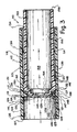
- Valve assembly 20 is illustrated in Figure 1 (as part of an IV administration set) in an operational or "as used" liquid control condition, i.e. here the slit valve assembly 20 is operatively interposed between a cannula in the form of a catheter tube, generally designated 24, and an IV tube, generally designated 26.
- the IV administration set use depicted in Figure 1 is only exemplary in that the present invention contemplates adjustable outdwelling slit valve control for selective delivery of liquid or gas to and from appropriate internal locations within a medical patient.
- the catheter tube 24, illustrated in Figure 1 may be of any available type and is illustrated as having a distal end portion 28 comprising a distal port 30 placed indwelling in the cardiovascular system of a medical patient, namely in the patient's vein 32.
- the catheter tube 24 comprises a proximal end portion 34, illustrated as being force-fit into or otherwise suitably positioned in liquid communicating relation with one part of the adjustable slit valve assembly 20.
- tube 26 may be of any desired type by which outdwelling medical liquid is selectively made available to the slit valve assembly 20.
- Tube 26 is illustrated as comprising a distal end portion 36 which may be force-fit into or otherwise suitably positioned in liquid communicating relationship with the adjustable slit valve assembly 20 at the other port thereof.
- Figure 1 further illustrates IV tube 26 as comprising a proximal end 44, which is illustrated as being suitably connected to an IV bottle 46 (shown suspended by a bracket 48 from a cantilevered support arm 50), all of which is conventional.
- IV solution in bottle 46 is selectively and controllably passed through valve assembly 20 at a desired rate into the vein 32 via catheter tube 24, responsive to pressure imposed by a hydrostatic head.
- the adjustable slit valve control assembly 20 is shown as generally comprising an externally exposed housing 52, an adjustment or control member 74, an exposed handle 82, a gasket or seal 81, a slit diaphragm 98, and a male connector element 88.
- housing 52 may be formed of any suitable material, the housing is illustrated as being formed of medical grade synthetic resinous material or plastic.
- Housing 52 comprises a relatively large annular or cylindrical wall 54, shown as being generally of uniform thickness and comprising a cylindrical exterior surface 56 and a concealed inner surface 58 which defines an internal cavity 68.
- an annular retention wall or inwardly directed radial flange 62 interrupts inner surface 58 and comprises a first radial surface 55, a second radial surface 57, and an annular orifice-defining edge surface 63 within which an aperture 61 ( Figures 8 through 10) is formed.
- the diameter of the surface 63 is shown as being less than that of the inside diameter of the wall 54 housing at surface 58.
- Threads 60 are formed on part of the housing inner surface 58, which threads commence immediately adjacent to and extend away from the annular retention wall or flange second surface 57.
- the purpose and function of the threads 60 and the annular retention wall or flange 62 will be hereinafter more fully explained.
- the cylindrical exterior surface 56 of housing 52 is interrupted by a cylindrical liquid flow port defining boss 64.
- the boss 64 is shown as being hollow and formed as one piece with and oriented substantially perpendicularly to the longitudinal axis of housing 52.
- Boss 64 comprises a boss exterior surface 69 and a hollow interior 66. defined by a boss inner surface 67, through which liquid selectively flows.
- the boss exterior surface 69 interrupts and merges with exterior surface 56 at exterior annular corner 65.
- the boss inner surface 67 intersects the housing interior surface 58 at interior annular comer 59.
- the hollow interior 66 is in direct open communication with the housing internal cavity 68.
- the cylindrical exterior surface 56 intersects at one end with annular edge surface 44 of housing 52 at exterior annular corner 38. At the other end thereof, exterior surface 56 merges with radial surface 41 of annular shoulder 70 at exterior annular corner 71. Similarly, housing inner surface 58 intersects with the shoulder interior surface 49 at annular interior corner 51.
- a reduced diameter or stepped cylindrical extension 72 of housing 52 extends from the annular wall 70 and comprises interior surface 73 and exterior surface 45 and is illustrated as being hollow, cylindrical, and formed as one piece with the housing 52.
- the interior surface 73 defines a hollow cylindrical interior 39 and is shown as comprising a diameter substantially less than the diameter of the housing inner surface 58. As shown, the interior surface 73 intersects with inner surface 49 at annular comer 47. Likewise, the exterior surface 45 intersects with the shoulder exterior surface 41 at annular exterior corner 43.
- the wall 72 terminates at blunt edge 40 which intersects the interior surface 73 at annular interior corner 39 and exterior surface 45 at annular exterior corner 42.
- the housing extension wall 72 is shown as being aligned or co-axial with the housing 52.
- the adjustment member or variable control 74 is adjustably disposed within housing 52.
- the adjustment member 74 is illustrated as having a threaded end 84, an elongated portion 80, an enlarged threaded portion 78 comprising threads 79 and a contact or abutment extension 76.
- the contact extension 76 is shown as comprising an annular ring which comprises a cylindrical inner surface 85, an exterior surface 89, and a radial contact surface 77.
- the contact surface 77 is oriented perpendicularly to and intersects with the inner surface 85 at annular corner 93 and with the exterior surface 89 at annular exterior corner 95.
- the interior surface 85 defines hollow portion or chamber 75 through which liquid selectively flows. As best illustrated in Figure 2, hollow portion 75 extends from surface 77 of the contact extension 76 a substantial distance into the elongated portion 80. terminating at flat surface 61.
- the enlarged diameter threaded portion 78 is illustrated as being formed adjacent to contact extension 76.
- Enlargement 78 is shown as being formed as one piece with the contact extension 76 and the elongated portion 80 of the adjustment member 74 and as comprising front wall surface 101 and rear wall surface 102.
- Wall surfaces 101 and 102 are shown as being substantially perpendicular to contact extension exterior surface 89.
- Wall surface 101 intersects with contact extension surface 89 at annular exterior corner 103.
- wall surface 102 intersects with an exterior surface 104 of the elongated portion 80 at annular exterior corner 105.
- Annular threads 79 are formed on the threaded portion 78 between walls 101 and 102. The diameter of the threaded portion 78 and the make-up of threads 79 are such that proper threaded engagement with housing threads 60 and adjustment member threads 79 occurs, as shown in Figure 2.
- the adjustment member threads 79 are threadedly engaged by the threads 60 formed on the housing inner surface 58. With such engagement of threads 79 and 60, the longitudinal position of adjustment member 74 within the housing 52 can be selectively set or varied by manually rotating the adjustment member or control 74 relative to the housing 52.
- a gasket 81 or seal in the form of an O-ring is disposed between the surface 104 and the surface 73.
- the gasket or O-ring 81 is compression-fit between the surfaces 104 and 73.
- the elongated portion 80 of the adjustment member 74 has two opposed transverse apertures 87 which extend transversely through the elongated portion 80 between the hollow interior 75 and the cavity 68.
- Each transverse aperture 87 is defined by a cylindrical surface 106 to permit fluid communication between the chamber 75 and the cavity 68.
- the adjustment member 74 also comprises a handle or knob 82 into which the threaded end 84 of the adjustment member 74 is non-rotatably secured to accommodate manual relocation of the adjustment member 74 within the housing 52.
- the handle 82 is shown as comprising a blunt transverse end wall comprising outer surface 38' and inner surface 99.
- the surface 99 comprises a threaded blind bore 86 to receivingly accept threaded end 84 of the elongated portion 80 in non-rotatable relation.
- the blunt end wall 38' merges as one piece with cylindrical wall 111 to form a cup-shaped member.
- Wall 111 comprises cylindrical interior surface 83 and cylindrical exterior surface 53 and is shown as being of uniform thickness. Cylindrical interior surface 83 joins annular front surface 99 at annular corner 97.
- the handle front surface 53 and surface 38 intersect at annular corner 107.
- the cylindrical exterior surface 53 provides a suitable gripping location from which a user may selectively rotate the handle 82 clockwise or counterclockwise and thus rotate the adjustment member 74. Such manual adjustment will after the pressure at which the slit 102 in the diaphragm 98 will open to the right as shown in Figure 2 and will change the amount of space between the diaphragm 98 and surface 55. without requiring the valve assembly 20 to be disconnected or disassembled.
- Surface 53 may be knurled or otherwise made to accommodate a secure manual grip.
- the male connector 88 comprises a planar base 92 which is radially disposed and comprises outer edge 108.
- a flow port defining annular boss 90 is shown as being formed as one piece with the planar base 92 and extends outwardly from the planar base at annular corner 94 in an axial direction.
- the annular boss 90 has an exterior surface 105 and an interior flow path-defining surface 109, which surrounds a hollow interior 91 therein.
- the connector edge 108 is sealed and secured within annular housing 52 at interior surface 96.
- the connector 88 may be secured within the inner surface 96 by bonding agent, adhesion, press-fit attachment, or in any other suitable way.
- the slit diaphragm 98 is interposed between the connector 88 and the annular retention wall 62.
- the diaphragm is contiguous with flange 62, but spaced at surface 55 from base 92.
- the slit diaphragm 98 is disk-shaped and advantageously formed of a suitable elastomeric material, such as silicone rubber. Silicone rubber offers the advantage of ease in accommodating controlled centrally flexing of the diaphragm and has good memory characteristics.
- the diaphragm 98 is illustrated in Figure 2 in an unstressed condition. Diaphragm 98 is planar and of uniform thickness, comprising peripheral edge 100, the unstressed diameter of which is slightly less than the diameter of the inner surface 96.
- Diaphragm 98 further comprises the centrally-disposed, normally-closed, transversely-directed linear slit 102.
- Slit 102 is illustrated as uniformly extending through diaphragm 98 and is located along the longitudinal access of the valve assembly 20 so as to be directly aligned with hollow interiors 91 and 75. when assembled.
- the radial length of slit 102 is selected to accommodate the desired range of distal and proximal flexing in order to accommodate selective bi-directional liquid flow through the flexed and opened slit 102 to introduce, for example, IV solution into the patient under hydrostatic IV pressure or to remove sample blood from the patient under negative pressure or to introduce medication into the bloodstream.
- hollow interiors 75 and 91 individually and collectively are variables to be set by those knowledgeable in the art in determining the range of pressure differentials by which the slit 102 is caused to be opened by flexing distally and proximally.
- the outdwelling fluid control devices according to the present invention can be freestanding, for addition to a cannula, such as a catheter or a needle, at the time of use or can be constructed as a component part of an IV cannula system at the time of manufacture.
- a cannula such as a catheter or a needle
- a pressure differential P 2 of a greater magnitude is required in order to cause the slit valve to be flexed sufficiently to open the slit 102 than when the slit diaphragm is permitted to flex without restriction.
- the contact surface 77 is moved farther from the unstressed position of the slit diaphragm 98, for example as shown in Figure 10, the slit diaphragm 98 is less restrained and to a greater extent thereby spreading the lips of the slit 102 a greater distance apart when subjected to pressure differential P 2 . This accommodates a larger rate of flow through the slit 102 from left to right.
- Figures 9 and 10 illustrate the slit diaphragm 98 being opened in one direction (toward the right) due to pressure differential P 2
- the slit diaphragm 98 may also be opened in the opposite direction by pressure differential P 1 , as illustrated in Figure 8.
- the pressure requirement to open the slit diaphragm. 98 in a direction away from the adjustment member or control 74 is not per se adjustable because the position of base 92 is fixed in respect to the diaphragm 98.
- Liquid flow across the diaphragm 98 when slit 102 is open in either direction is generally axial on both sides of the diaphragm 98.
- the flow between chamber 75 and cavity 68 is somewhat radial or transverse and the influent or effluent into and from cavity 68 is radial or transverse within the boss 64.
- FIGS 3 and 7 illustrate another embodiment of the invention, designed to control gas flow, namely an adjustable slit valve control mechanism 110 which also permits adjustment in the gas pressure threshold or differential required to open the valve mechanism 110.
- the adjustable slit valve control mechanism 110 as shown, comprises a hollow cylindrical housing 112, an adjustment member or manual control 134, a slit diaphragm 128, a retainer 124, and an O-ring seal or gasket 138.
- Housing 112 is illustrated as comprising a cylindrical wall 113 comprising exterior surface 114 and an inner surface 118.
- the interior surface 118 is interrupted by an annular retention wall or flange 116 formed as one piece with the wall 113.
- the annular retention wall or flange 116 extends radially inwardly and comprises a front radial surface 115, a rear radial surface 117, and an interior edge surface 119.
- the interior surface 119 defines an aperture or orifice 121, the diameter of which is shown as being less than the diameter of the housing interior surface 118.
- housing threads 120 are shown as commencing at a location adjacent to annular surface 117 and extending a significant distance along the housing interior surface 118 from left to right as viewed in Figure 3. The purpose and function of the housing threads 120 will be hereinafter more fully explained.
- the housing 112 comprises a cylindrical wall segment 122, extending from right to left from flange 116 and comprising an extension of wall 113.
- Wall segment 122 is illustrated as being formed as one piece with the rest of housing 112.
- the extension or wall segment 122 is hollow, of uniform thickness, and comprises an inner surface 126.
- Extension 122 terminates at blunt, radially-directed edge 127.
- slit diaphragm 128 is contiguous at its periphery with surface 115 of inwardly-directed flange 116.
- a retainer ring 124 is positioned within the annular housing extension 122 to be peripherally contiguous with the opposite side of the diaphragm 128. This secures the slit diaphragm 128 within the housing 112 between the retainer ring 124 and the retention flange 116.
- the retainer ring 124 comprises an interior edge surface 125. an exterior edge surface 123, and is illustrated as being of uniform thickness. The diameter of the interior surface 125 is shown as being approximately the same as the diameter of the surface 119.
- the diameter of the retainer ring outer surface 123 is illustrated as being approximately the same as the diameter of the annular housing extension inner surface 126.
- the retaining ring may be secured within the housing extension 122 by a bonding agent or adhesion, a press-fit relationship plastic welding, or in any other suitable way.
- Slit diaphragm 128 is shown as being compressively interposed between retention wall 116 and retainer 124 against separation.
- the slit diaphragm 128 comprises slit 129 formed centrally therein and has the type of the characteristics and features described above in connection with slit diaphragm 98. Accordingly, no further description of the slit diaphragm 128 is necessary.
- Adjustment member or control 134 is threadedly disposed within the housing 112 so as to be co-axial therewith.
- the adjustment member 134 is illustrated as comprising an enlarged threaded portion 137, an elongated cylindrical wall portion 139, and a contact extension, nose portion or abutment wall 141.
- the contact extension 141 comprises an inwardly-directed radial-oriented annular ring which comprises an annular orifice-forming interior surface 130, and flat surface 131, a peripheral edge surface 131' and a diaphragm contact surface 136.
- the contact surface 136 is illustrated as being oriented perpendicularly to and intersecting with the interior surface 130 at annular corner 133 and with the peripheral surface 131 ' at annular corner 135.
- Interior surface 130 defines aperture 143 through which liquid selectively flows.
- aperture or orifice 143 extends axially through the contact extension 141 into elongated portion interior cavity 154, which is defined by interior surface 156 of wall 139.
- the interior surface 156 extends from annular blunt edge 158 of wall 139 to annular corner 160 where interior surface 156 intersects interior annular shoulder surface 162.
- the annular shoulder surface 162. which is radially oriented, intersects the cylindrical interior extension surface 164 of wall 164' at corner 166.
- the enlarged diameter threaded portion 137 is illustrated as being adjacent and connected to contact extension 141 by wall 164'.
- the threaded portion 137 is shown as being formed as one piece with the contact extension 141, wall 164' and elongated portion 139 of the adjustment member 134.
- the threaded portion 137 comprises radially-directed front wall surface 145 and radially-directed rear wall surface 146.
- Wall surfaces 145 and 146 are illustrated as being substantially perpendicular to the longitudinal axis of valve assembly 110.
- Wall surface 145 intersects with contact extension surface 131 at annular corner 147.
- wall surface 146 intersects with the exterior surface 153 of the elongated portion 139 at annular corner 148.
- Threads 132 are formed on the enlarged diameter threaded portion 137 between walls 145 and 146 and are oriented so as to be parallel with the housing inner surface 118.
- the diameter, size, shape, location, and orientation of the adjustment member threads 132 are such that the proper, adjustable, threaded engagement between housing threads 120 and adjustment member threads 132 occurs, as shown in Figure 3.
- the longitudinal position of adjustment member 134 within the housing 112 can be selectively changed by manually rotating the adjustment member 134 clockwise or counter clockwise relative to the housing 112.
- O-ring 138 is disposed therebetween. As illustrated in Figure 3. the O-ring type gasket 138 is compression-fit between the exterior surface 153 and the surface 118.
- a primary function of the adjustment member contact surface 136 is to selectively be engaged by the slit diaphragm 128.
- Contact surface 136 selectively restricts flexure of the slit diaphragm 128 in the direction of the contact surface 136.
- Adjustment of the space between the diaphragm 128 and surface 136 (via rotation of control 134), adjusts the pneumatic pressure requirement necessary to open the slit 129 of diaphragm 128. This is illustrated in Figures 12 and 13.
- the contact surface 136 is closer to the slit diaphragm 128 and, therefore, the flexure of the slit diaphragm 128 in the direction of the contact surface 136 becomes increasingly restricted.
- the slit diaphragm 128 when the adjustment member 134 is moved farther from the unstressed, closed position of the slit diaphragm 128, the slit diaphragm 128 may be more substantially flexed sufficiently to open by a predetermined pressure differential, of significantly less magnitude than the pressure differential required to open the slit diaphragm 128 when restricted as shown in Figure 12.
- slit diaphragm 128 may also be opened at slit 129 by flexure in a direction away from adjustment member 134 due to an oppositely directed pressure differential P 1 of predetermined threshold magnitude.
- the location of control 134 is essentially immaterial when the pressure differential is toward the left as in Figure 11. Because in Figure 11 there is an adjustment member 134 disposed on only one side of diaphragm 128, the pressure requirement to open the slit diaphragm in a direction away from the adjustment member is not per se adjustable.
- an adjustment member or control may be placed on each side of the slit diaphragm.
- the dual controls may be used to selectively adjust the amount of pressure required to open a slit diaphragm in either direction.
- adjustable slit valve assemblies are illustrated which accommodate bi-directional flow and bi-directional pressure requirement adjustment are illustrated.
- the left and right hand sides of the valve assembly embodiments of Figures 4 and 5, respectively comprise mirror images on opposite sides of the slit diaphragm of embodiments illustrated in Figures 2 and 3. respectively, and described above.
- bi-directional pressure requirement adjustment valve control assembly 140 is illustrated as comprising a single housing which comprises two oppositely extending housings 52 formed as one piece two opposed adjustment members 74 are oppositely adjustably disposed one in each of housings 52. Interposed between adjustment members 74 is slit diaphragm 98, which is secured between the two annular retention walls 62.
- One of the cylindrical liquid flow port defining bosses 64 is communicably attached to a catheter tube 24 while the other is attached to an IV tube 26 (as illustrated in Figure 1). Due to the structural and operational identity between the two halves of the embodiment of Figure 4 and the above-described embodiment of Figure 2, no further structural description of the Figure 4 embodiment is necessary.
- the pressure requirements necessary to open slit diaphragm 98 of bi-directional valve control assembly 140 can be selectively adjusted in any desired way, for example, so that, in each direction, they are different.
- the adjustment member 74 on the left-hand side is displaced closer to the slit diaphragm 98. thereby increasing the degree of restriction of the silt diaphragm flexure in the left-hand direction.
- the adjustment member 74 is brought closer to the slit diaphragm 98 by rotating the adjustment member 74 relative to the housing 52. so that the adjustment member 74 can threadedly advance longitudinally in respect to housing 112.
- the adjustment member 74 on the left-hand side is moved away from slit diaphragm 98 so as to reduce or eliminate the amount of restriction of the flexure of the slit diaphragm 98 in the left-hand direction, thereby permitting the slit diaphragm 98 to be opened by flexure in the left-hand direction by a lesser pressure differential than when the contact surface 77 is disposed near the slit diaphragm.
- similar adjustments can be made on the right-hand side of valve control assembly 140 to adjust the pressure differential requirement necessary to open the slit diaphragm by flexure in the right-hand direction.
- the pressure differential requirement necessary to open the slit valve in either the left-hand or the right-hand direction or both can be easily adjusted.
- the valve control 140 can be adjusted so that the pressure requirement necessary to open the slit valve in one direction is different from the pressure requirement necessary to open it in the other direction.
- the adjustment member 74 on the left-hand side is positioned closer to the slit diaphragm 98 than the adjustment member 74 on the right-hand side.
- the flexure of the slit diaphragm 98 in the left-hand direction will he more restricted than the flexure in the right direction and a greater pressure differential therefore will he needed to open the slit valve in the left-hand direction than in the right-hand direction, assuming adjustment member inside surfaces 85 have equal diameters.
- Figure 5 illustrates a yet further pneumatic embodiment of the present invention.
- Figure 5 illustrates bi-directional pressure requirement adjustable valve assembly 142.
- the left-hand side of valve control assembly 142 comprises a mirror image of the adjustable tlow control mechanism 110 of Figure 3 taken about the slit diaphragm 128. Accordingly, both left and right-hand features of the valve control assembly 142 are designated with the same numerals as the same features in Figure 3. already described. Due to the structural identity between each of the two halves of the embodiment of Figure 5 and the embodiment of Figure 3, no further structural description of the structural features of the Figure 4 embodiment is necessary.
- valve control assembly 142 comprises two adjustment members or controls 134 movingly disposed within a housing 112 on opposite sides of a slit diaphragm 128.
- the slit diaphragm 128 is shown as being peripherally secured between two retention walls 116 integrally formed on the housing inner surface 118.
- O-ring gaskets 138 are provided between adjustment member exterior surface 153 and housing interior surface 118.
- valve control assembly 142 permits bi-directional adjustment of the pressure requirement necessary to open the slit diaphragm 128 in either direction by selectively varying flexure available to the slit diaphragm using the adjustment members 134.
- the hollow interior of one of the adjustment members 134 is liquid communicably attached to a ventilating tube, while hollow interior of the other adjustment member 134 is liquid communicably attached to a respiratory tube.
- the adjustment member 134 on the left-hand side is moved closer to the slit diaphragm 128.
- the adjustment member is brought closer to the slit diaphragm 128 by threadedly rotating adjustment member 134 relative to housing 112, so that adjustment member 134 is threadedly advanced longitudinally through housing 112.
- flexure of the slit diaphragm 128 is restricted in the right-hand direction as well.
- the adjustment member 134 on the right-hand side is moved closer to the slit diaphragm 128.
- the diaphragm more rapidly engages the member 134, which restricts its flexure in the right-hand direction. thus requiring a greater pressure differential in the right-hand direction to open the slit valve than would be the case if the adjustment member 134 were spaced a greater distance from the diaphragm 128.
- Flow control valve assembly 142 may be adjusted so that the pressure requirements to open the slit valve in the left-hand direction are different from the pressure requirements necessary to open the slit diaphragm 128 in the right-hand direction. This is done by selectively placing the left and right-hand adjustment members at different distances from the slit diaphragm 128.
- markings may be advantageously provided to enable measurement of the relative positions of the various adjustment members within the housings and relative to the slit diaphragms of the various embodiments.
- This is advantageous due to the valve control feature that the relative positions of an adjustment member and a slit diaphragm define a pressure differential necessary to open the slit valve in a given direction. By measuring these relative positions, the user is able to selectively choose a desired pressure differential by adjusting the relative positions of the slit diaphragm and the adjustment member to predetermined positions.
- markings 144 are provided on the housing extension 72 to permit the user to gauge the position of the handle 82 relative to the housing extension 72.
- markings 150 are provided on the adjustment member 134 external surface to permit the user to gauge the position of the adjustment member relative to the housing 112.
- FIG. 2 through 13 An inspection of Figures 2 through 13 makes it clear that the embodiments depicted therein, which embrace principles of the present invention, accommodate generally axially-directed liquid or gas flow adjacent to each side of the slit valve diaphragm.
- the flow on each side of the diaphragm is generally axially directed and is not diverted.
- the axial flow adjacent to one side of the diaphragm is within a chamber of the control or adjustment member. This chamber flow is diverted from the axial into a somewhat transverse and circuitous path within the associated valve housing and ultimately is radial or transverse flow at ports 66.
- Figures 14 and 15 respectively illustrate two further slit valve/control assemblies, generally designated 170 and 172. While the embodiments of Figures 14 and 15 are specifically for variable control of liquid flow, the same basic principles of the present invention apply to variable control of gas flow. In each of these two embodiments, flow on the control side of the diaphragm is diverted in more or less a radial direction adjacent to the diaphragm and circuitously beyond that, all within the interior of the valve assembly. In other words, linear flow directly into the control or adjustment member adjacent to the diaphragm is prohibited and the control serves not only to vary the pressure differential threshold for opening of the slit in the diaphragm in the direction of the control, but as a flow diverting member as well.
- assembly 170 comprises a cylindrical housing, generally designated 174.
- Tubular housing 174 carries an end cap, generally designated 176, at one end 178 thereof.
- the other end of the cylindrical housing 174 comprises an annular opening 180 through which a diaphragm threshold control/flow diverting member, generally designated 182, is inserted into the hollow interior of the cylindrical housing 174 during assembly.
- Threshold control/flow diverter 182 comprises a manual knob 184 by which the position of the control/diverter 182 may be axially varied within the hollow interior of the cylindrical housing 174.
- Housing 174 comprises a cylindrical wall 186.
- Wall 186 comprises a cylindrical or annular exterior surface 188, illustrated as being of uniform diameter throughout.
- Wall 186 also comprises a smooth cylindrical or annular interior surface 190 of a predetermined diametral size.
- Internal surface 190 is interrupted hy a groove 191 and includes threads 192 adjacent to annular opening 180. Threads 192 merge at corner 194 with a radially-directed surface or shoulder 196. Shoulder 196 merges at comer 198 with annular surface 180.
- Annular surface 180 merges at annular corner 200 with a blunt end edge 202 of wall 186.
- Boss 204 comprises a cylindrical wall which terminates at a blunt edge 206, defines a hollow flow path at interior cylindrical surface 208 and comprises an exterior cylindrical or annular surface 210. Annular surface 210 merges with surface 188 at annular inside corner 212.
- the forward end 178 of wall 186 is stepped at shoulder 214 to a reduced diametral size.
- Shoulder surface 214 merges at corner 216 with cylindrical surface 218.
- Cylindrical surface 218 merges at corner 220 with blunt, radially-directed end surface 222 of wall 186.
- Edge surface 222 merges at outside corner 224 with the hollow interior cylindrical surface 190.
- a flat diaphragm 226 is contiguously superimposed upon blunt end surface 222 near the periphery of the diaphragm 226.
- the diaphragm 226 is illustrated as being formed of suitable elastomeric material, such as silicone rubber, and is circular or disk-shaped in its configuration.
- Diaphragm 226 comprises peripheral edge 228. which is compressively held against inadvertent release, opposed radially directed surfaces 230 and 232, and a central slit 234 of predetermined length.
- Slit 234, in its closed position comprises opposed lips which are contiguous one with the other.
- End cap 176 comprises an annular. axially-directed wall 240, which comprises an end edge surface 242 sized and shaped so as to he flush with surface 214.
- Annular wall 240 comprises a thickness substantially the same as the radial length of wall 214, the thickness being illustrated as uniform throughout wall 240.
- Wall 240 comprises an exterior annular surface 241 and an interior surface which is bonded, glued, or plastic welded to surface 218.
- Wall 240 merges with radially-directed annular wall 244. which is illustrated as being of uniform thickness and as comprising opposed radially directed surfaces 246 and 248.
- Wall 244 is illustrated as merging as one piece with wall 240 at inside and outside corners 250 and 252.
- Radially-directed annular wall 244 is interrupted by axially-directed boss 254.
- Boss 254 comprises a cylindrical wall which merges at corners 256 and 258 with wall 244.
- Cylindrical wall 254 is illustrated as being of uniform thickness comprising interior cylindrical surface 260 and exterior cylindrical surface 262.
- Wall 260 defines a liquid flow path on one side of the diaphragm 226.
- Wall 254 terminates in blunt end edge surface 264.
- Bosses 204 and 254 are sized and shaped to receive, in a compression fit relationship, tubing through which liquid selectively flows in the manner illustrated and described in conjunction with Figure 1.
- cylindrical housing 174 and end cap 176 are separately formed from the suitable medical grade synthetic resinous material in accordance with the exercise of skill by artisans in the field.
- flow occurs selectively across the diaphragm 226, i.e. only when the slit 234 is caused to be opened responsive to a predetermined pressure differential (net pressure).
- the flow is between the internal chambers defined by the hollow cylindrical surfaces 208 and 260, respectively, of bosses 204 and 254.
- control/diverter 182 is secured against inadvertent removal from housing 174, but is axially adjustable in respect to housing 174 in a manner and for purposes hereinafter more fully described.
- Control/diverter 182 is generally cylindrical and is stepped in its external configuration.
- the distal cylindrical portion 270 comprises a cylindrical surface 272, the diametral size of which is substantially smaller than the diameter of surface 190, but larger than the diameter of surface 260.
- Distal cylindrical end 270 of control/diverter 182 is illustrated as being internally solid and comprises a blunt, impervious, radially directed distal end surface 274.
- Surfaces 272 and 274 serve, among other functions, to divert liquid flow into a stepped pattern between the boss passageways defined by surfaces 208 and 260.
- Cylindrical surface 272 which is axially directed, merges at annular inside corner 276 with an outwards-directed, radially-oriented cylindrical shoulder 278.
- Shoulder 278 merges at annular outside corner 280 with a diametrally enlarged solid cylindrical body 282, which comprises surface 284.
- the diameter surface 284 is only slightly less than the diameter of surface 190, allowing axial and rotational displacement between surfaces 190 and 284.
- the small space between surfaces 190 and 284 is sealed so as to prevent flow of liquid thereacross by compressed O-ring 286 disposed in annular groove 191.
- the proximal end of cylindrical body 282 comprises threads 288 at surface 284, which threads are sized. shaped. and configured so as to snugly and compatibly engage threads 192.
- the threaded portion 288 merges at annular outside corner 290 with a radially-directed shoulder or surface 292, which in turn merges at inside corner 294 with cylindrical segment 296.
- Cylindrical segment 296 is illustrated as being solid and as comprising an exterior cylindrical surface 298. Surface 296 is stepped at shoulder surface 300, the merger between surface 298 and surface 300 occurring at annular inside corner 302.
- Annular surface-304 of knob 184 can comprise a surface texture and merges with blunt proximal end surface 308 at outside annular corner 310.
- the medical attendant manually rotates control knob 184 until blunt distal surface 274 is spaced a desired distance from the diaphragm 226 so that the slit 234 in the diaphragm 226 opens. in a downward direction, at precisely the desired net pressure or pressure differential threshold.
- the medical attendant may at any time vary the distance between the blunt surface 274 and the diaphragm 226. by rotation of the knob 184, to alter, as advisable and appropriate for the patient, the pressure differential threshold at which the slit 234 opens in a downward direction.
- valve assemblies 170 can be used in opposed relation (similar to the Figure 4 and 5 arrangements) so that the pressure threshold for flow in either direction across the diaphragm 226 may be selectively varied by the medical attendant, as appropriate for the patient. Variations in the pressure differential threshold at which the slit 234 in diaphragm 226 opens is manually controlled by proper manipulation of knob 184 and does not require that the assembly or assemblies 170 be disconnected or disassembled.
- FIG. 15 depicts a diaphragm control/flow diverting slit valve assembly 172.
- assembly 172 comprises previously described diaphragm 226 and end cap 176 and a slight variation of the cylindrical housings.
- Cylindrical housing 174' of Figure 15 differs only from housing 174 of Figure 14 that the boss 204 has been eliminated in housing 174 and the cylindrical wall 186 does not accommodate radially-directed liquid flow. Accordingly, the various parts and characteristics of diaphragm 226, cylindrical housing 174', and end cap 176 are numerated identically in Figure 15 as in Figure 14. Since these components were earlier described in conjunction with Figure 14, no further description is needed in conjunction with Figure 15.
- Control/diverter 320 is generally cylindrical and is stepped diametrally in a manner and for purposes explained below.
- Control/diverter 320 comprises a distal diamctrally-reduced generally cylindrical portion 322.
- Portion 322 comprises a distal blunt flow-diverting end edge surface 324, which is generally parallel to the orientation of diaphragm 226.
- Surface 324 is circular and merges at annular outside corner 326 fixed with an exterior cylindrical surface 328.
- Generally cylindrical portion 322 defines an internal blind bore which ends with blunt, radially-directed interior wall surface 330.
- Surface 330 is circular and illustrated as being parallel to surface 324.
- Circular surface 320 merges at annular inside corner 332 with internal cylindrical surface 334.
- Cylindrical surface 334 is axially-directed and defines a hollow interior which functions as a flow path for liquid.
- Surfaces 324 and 334 comprise outside and inside surfaces of a cylindrical wall 336, which is interrupted by opposed apertures or orifices 338.
- Orifices 338 are illustrated as being of the same diameter and oriented so as to accommodate generally radially directed flow between the hollow chamber 340, defined by wall 334, and a distal chamber 342 disposed between distal cylindrical portion 322 of control/diverter 320, the interior surface 190 of cylindrical housing 174' and surface 232 of diaphragm 226.
- Cylindrical portion 322 of control/diverter 320 merges at annular corner 344 with a radially-directed annular surface 346.
- Shoulder surface 346 merges, as one piece, at outside annular corner 348 with main cylindrical body 350.
- Main cylindrical body 350 comprises an outside generally cylindrical surface 352 as well as previously mentioned interior, chamber-defining surface 334.
- Body portion 350 is illustrated as being solid except for hollow chamber 340.
- Surface 352 comprises threads 354 at a proximal portion thereof. Threaded outside corner 356 merges with a radially-directed shoulder surface 358, which in turn merges at inside annular corner 360 with a diametrally reduced cylindrical surface 362, which comprises the outside of a cylindrical wall 364.
- the inside surface of wall 364 comprises previously mentioned surface 334.
- Annular wall 364 terminates in radially-directed blunt end edge surface 366, which merges at annular corner 368 with surface 362 and at corner 367 with surface 334.
- Assembly 172 in use, is serviced by two flow tubes, one of which is force-fit or compression-secured over boss 254 and the other of which is compression-fit over surface 362.
- Flow between the two tubes occurs along the passageway defined by surface 260 of boss 254, through cavity 342 and along chamber 340.
- Flow across the diaphragm 226 into and from the cavity 342 is along surface 324, across surface 328, through apertures or orifices 338 and along chamber 342.
- the spacing between the diaphragm 226 and surface 324 can be adjusted by manual rotation of the control/diverter 320 to create a pressure differential threshold response necessary to open slit 234 precisely as desired by the medical supervisor.
- Rotation of the control/diverter 320 can include counter rotation of the liquid-communicating tubing force fit upon surface 362 or, in the alternative, tubing can be temporarily removed from surface 362, the control/diverter 320 rotated and the tubing force-fit over surface 362 once more.
- adequate medical care must be taken to insure that such a procedure does not create inappropriate medical circumstances and risks for the patient.
- Two valve assemblies 172 can be used in opposed relation so that the pressure threshold for flow in either direction across the diaphragm may be selectively varied in the manner explained above.
Abstract
Description
- The present invention relates generally to improvement in the accuracy of medical liquid and gas flow control in a cannula, and more particularly to novel structure and methods for very accurate outdwelling selective slit valving of medical liquid flow, including a selectively settable control for varying pressure actuated thresholds and the degree to which the slit may open and close in one or both directions, the outdwelling slit valve being in association with a liquid-carrying cannula, such as a hollow catheter tube or needle, or, in the case of gas, a ventilating tube.
- Valuable prior medical inventions pertaining to fluid flow (flow of liquids and gases) to and from a medial patient are acknowledged. Nevertheless, to some important extent, control of when and to what extent liquid and gas flow is permitted into and from a patient has been a long standing need in certain medical applications. Control of gas and liquid flow can be critical to the care for the patient. Flow of liquid to and from the patient includes but is not limited to infusion of intravenous liquid into the cardiovascular system and removal of blood samples. Flow of gas typically involves the respiratory system of the patient, including but not limited to preventing the patient from exhausting all gas within the lungs during exhalation. to thereby keep the air sacks in the lungs partially inflated and, therefore, continuously open. Control of gas and liquid flow can be critical to the care for the patient.
- More specifically, in respect to liquid flow to the patient, it has long been recognized to be medically desirable to intravenously infuse a predetermined liquid into and to sample blood or other liquids from a patient. Typically, during delivery of IV solution to the patient through an infusion administration set comprising a cannula, such as a catheter tube or IV needle, it is difficult to accurately predict the point in time when the supply of IV solution will become exhausted. It is even more difficult to coordinate availability of nursing personnel to timely disable the IV administration set to prevent flow from a soon-to-be dry IV supply through the catheter tube or needle. As a consequence, the distal tip of the cannula sometimes experiences bleed-back and clotting. Also, as a container of IV solution progressively empties, a corresponding change in the hydraulic head takes place. As a consequence, a desired well regulated drip rate is not conventionally available.
- More specifically, when a conventional IV administration set is connected to a patient, the flow of IV solution occurs because the force of gravity upon the solution in the elevated container exceeds the blood pressure in the cardiovascular system of the patient to the extent permitted by a manually-controlled drip mechanism. As the supply of IV solution is progressively used until exhausted, the pressure difference changes until there is no pressure component from the IV solution.
- When the availability of IV sotution is undesirably exhausted or low, the cardiovascular pressure prevails. causing blood flow into the IV catheter tube for a distance, which may vary depending on circumstances. Sometimes, this blood flow reaches, contaminates, and requires replacement of an IV filter, forming a part of the IV administration set. In any event, the aforesaid blood in the catheter will clot, within a short time. Subsequent negligent introduction of the clot into the bloodstream becomes a risk, which, if not discovered, places the patient at jeopardy. If timely discovered, replacement of the IV system is required.
- Also, where the patient raises the venipuncture site above the IV container, refluxing or bleedback flow of blood into the distal end of the cannula sometimes occurs. This reflux may or may not reach the filter of the IV administration set, but, in either event, causes IV flow to stop, which results in clotting within either the cannula, the filter. or both. When and if discovered, both the clotted IV filter and catheter tube are replaced. This is disadvantageous because of accompanying patient trauma, expense, and risk. It is bad practice and an unacceptable risk to the patient to force a clot from the catheter tube into the bloodstream, but, due to negligence, this sometimes happens.
- It is known to use a standard one-way outdwelling (outside the patient) valve to prevent undesired blood flow into the distal end of an indwelling cannula, such as a catheter tube or IV needle. This standard one-way valve will not allow blood sampling when the standard one-way valve is located between the catheter tube and the sampling site.
- It has also been proposed that a two-way outdwelling slit valve (such as that disclosed in commonly owned U.S. Letters Patent No. 5,205,834) be used. With such a two-way outdwelling slit valve which has great medical value, the pressure requirements to open the slit valve are substantially fixed, i.e. built into the valve at the time of manufacture. The desired pressure requirement to open the slit valve in one direction of flow can be different than to open it in the other direction of flow.
- Another two-way outdwelling slit valve is known from US 5,201,722. Apertures of different size on either side of a diaphragm ensure that different pressure differentials are required to open the slit valve in each direction. After assembly of this slit valve, its operating conditions have become fixed, in particular by the housing parts of this slit valve having been glued together. There is no possibility any more to adjust the pressure differentials required for operation of the valve.
- Prior out-dwelling slit valves which are not readily adjustable, typically require a relatively high degree of manufacturing precision to ensure that the resulting valve opens in a given direction at the desired threshold.
- In certain medical applications, it has been found desirable for outdwelling slit valves of the type disclosed in U.S. 5,205,834 be inventively extended into environments where the characteristics of the valves may be varied for control and adjustment purposes. For example, use of an outdwelling slit valve having variable characteristics in lieu of a mechanical drip controller, if inventively achieved would overcome or substantially alleviate the problems mentioned above concerning the IV administration sets.
- Turning to flow of gases, proper respiratory care for the patient likewise requires precise control of the types and quantities of gases delivered to and expelled from the respiratory system of the intubated patient. When the patient is afflicted with some form of lung disease, the patient is typically placed on a respirator or ventilator. Sometimes controlled amounts of pure oxygen are cyclically delivered to the patient. Gas born medications are likewise sometimes introduced into the lungs on a controlled or metered basis. To prevent collapsing of the air sacks in the lungs, in the past, a C-PAP valve has been used to limit exhalation and prevent complete gas discharge from the lungs.
- Reliability and precision of gas flow control devices, such as the C-PAP valve, for use with the respiratory system of a patient have presented persistent problems. Almost constant or regular intermittent overseeing has often been required by a medical provider in order to insure that errors and malfunction of such prior art gas flow control devices do not work adversely to the best interests of the patient.
- There has long existed a need for a gas flow control which is precise, reliable, and unlike the present C-PAP valves, for example, does not require substantial ongoing monitoring by a nurse or other medically trained person.
- In brief summary, the present invention overcomes or substantially alleviates problems of the prior art and extends valuable outdwelling slit valve technology into the variable characteristics realm for significant medical purposes. Novel outdwelling, normally-closed, pressure-responsive medical slit valve assemblies are provided for controlling certain types of flow of liquid and gas to and from a patient where flow characteristics can be selectively varied. Each slit valve assembly comprises a readily adjustable control to selectively set and alter the pressure differential threshold or thresholds at which the slit valve opens and closes in one or both directions and the degree of flexure accommodated. Related methods are also provided. In certain embodiments of the invention, the control may he characterized as a diaphragm flex adjustment mechanism. Thus, in accordance with the present invention, the pressure requirements necessary to open the slit of the valve in a given direction can be quickly varied, as medically appropriate. Accordingly, the present invention provides novel slit valve mechanisms, and related methods, each valve mechanism comprising a control by which flow characteristics thereof in one or both directions can be selectively, immediately, and conveniently altered..
- With the foregoing in mind. it is a primary object of the present invention to overcome or substantially alleviate problems associated with prior art medical liquid and gas flow controls for flow liquid and/or gas to and/or from a medical patient.
- Another object of importance is the provision of a two-way slit valve, and related methods, which comprise an adjustable control by which the flow characteristics thereof in directions are selectively and conveniently altered.
- A further paramount object is the provision of a two-way outdwelling slit valve wherein the flow characteristics thereof can be selectively varied.
- It is an object of considerable value to provide an outdwelling slit valve mechanism wherein the degree of flexure of a flexible diaphragm is selectively restricted by an adjustable control.
- It is another dominant object to provide a two-way outdwelling valve structure of relatively simple design and is adjustable to alter the flow characteristics thereof.
- It is another object of significance to provide a normally-closed adjustable outdwelling slit valve, the flow characteristics of which can be changed.
- A further valuable object is the provision of an outdwelling slit valve control for use in an IV administration set to control the IV drip.
- A further paramount object is the provision of normally closed outdweliing slit valve mechanisms comprising selectively settable controls for changing the flow/non-flow characteristics thereof.
- Another important object is the provision of an adjustable outdwelling slit valve wherein the internal gas or liquid flow adjacent the slit is either generally axial or is diverted and non-axial in whole or in part or some of both.
- It is another valuable object to provide an outdwelling threshold adjustable slit valve which can be used to control respiratory gas flow in respect to a medical patient.
- An additional dominant object is the provision of a normally closed slit valve for use in lieu of a C-PAP valve to prevent full discharge of gas from the lungs of an intubated patient.
- These and other objects and features of the present invention will be apparent from the detailed description taken with reference to the accompanying drawings.
-
- Figure 1 is a perspective of one adjustable, outdwelling, two-way, normally closed, pressure-responsive slit valve liquid flow control embodying the principles of the present invention, shown in an installed condition as part of an IV administration set;
- Figure 2 is an enlarged cross section, taken along lines 2-2 of Figure 1 having both generally axial and diverted non-axial internal liquid flow, usable, for example. in conjunction with the cardiovascular system of a medical patient;
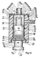
- Figure 3 is a cross section of a normally closed valve structure embodying principles of the present invention wherein the proximal and distal ingress and egress ports for gases are in direct alignment and internal gas flow is generally axial, usable, for example, to prevent full discharge of gas from the lungs of a patient:
- Figure 4 is a cross section similar to Figure 2 but depicting a normally closed valve structure embodying principles of the present invention comprising control features for adjusting and regulating liquid flow bi-directionally and having both generally axial and diverted non-axial internal liquid flow;
- Figure 5 is a cross section similar to Figure 3 of a normally closed valve structure embodying principles of the present invention comprising control features for adjusting and regulating gas flow bi-directionally where internal gas flow is generally axial;
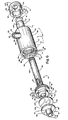
- Figure 6 is an exploded perspective of the valve structure of Figure 2;
- Figure 7 is an exploded perspective of the valve structure of Figure 3:
- Figure 8 is an enlarged, fragmentary cross section showing the central slit of diaphragm of the valve assembly of Figure 1 flexed left into an open condition by a threshold pressure-differential P1;
- Figure 9 is an enlarged fragmentary cross section showing the central slit of the diaphragm of the valve assembly of Figure 1 flexed right into an open condition by a threshold pressure differential P2, the flexure of the slit diaphragm being partially constrained by the adjustable control;
- Figure 10 is an enlarged fragmentary cross section similar to Figure 9 with the adjustable control spaced a greater distance from the diaphragm accommodating a greater flexure to the right of the slit in the diaphragm:
- Figure 11 is an enlarged, fragmentary cross section of the slit valve of Figure 3 flexed open to the left due to pressure differential P1 with the control closely spaced from the diaphragm;
- Figure 12 is an enlarged, fragmentary cross section of the slit valve of Figure 3 flexed open to the right due to pressure differential P2, the flexure of the slit diaphragm being partially constrained by the control, which is closely spaced from the diaphragm;
- Figure 13 is an enlarged, fragmentary cross section similar to Figure 12 of the slit valve of Figure 3 flexed open to the right due to pressure differential P2, the flexure of the slit diaphragm being less constrained than in Figure 12 with the control spaced a greater distance from the diaphragm;
- Figure 14 is a longitudinal cross section of a further selectively settable outdwelling slit valve assembly accommodating diverted internal flow; and
- Figure 15 is a longitudinal cross section of still another selectively settable outdwelling slit valve assembly accommodating diverted internal flow.
-
- Reference is now made to the drawings wherein like numerals are used to designate like parts throughout. Figures 1, 2, and 6 illustrate one configuration of an adjustable, pressure responsive, outdwelling slit valve and control mechanism or assembly in accordance with principles of the present invention. This embodiment is specifically designed for use with the cardiovascular system of a medical patient. Figures 3 and 7 illustrate a second configuration of an adjustable slit valve control mechanism or assembly in accordance with principles of the present invention. This embodiment is specifically designed for use with the respiratory system of a medical patient. Figures 4 and 5 illustrate two additional adjustable valve embodiments which enable bi-directional adjustment of the pressure requirement of the slit valve control mechanism or assembly. Figures 8 through 13 illustrate various control settings and the effect of different pressure differentials across the slit diaphragm, while Figures 14 and 15 illustrate further embodiments of the invention having control-diverted internal flow.
-
Valve assembly 20 is illustrated in Figure 1 (as part of an IV administration set) in an operational or "as used" liquid control condition, i.e. here theslit valve assembly 20 is operatively interposed between a cannula in the form of a catheter tube, generally designated 24, and an IV tube, generally designated 26. It is to be appreciated that the IV administration set use depicted in Figure 1 is only exemplary in that the present invention contemplates adjustable outdwelling slit valve control for selective delivery of liquid or gas to and from appropriate internal locations within a medical patient. - The
catheter tube 24, illustrated in Figure 1, may be of any available type and is illustrated as having adistal end portion 28 comprising adistal port 30 placed indwelling in the cardiovascular system of a medical patient, namely in the patient's vein 32. Thecatheter tube 24 comprises aproximal end portion 34, illustrated as being force-fit into or otherwise suitably positioned in liquid communicating relation with one part of the adjustableslit valve assembly 20. - Likewise,
tube 26 may be of any desired type by which outdwelling medical liquid is selectively made available to theslit valve assembly 20.Tube 26 is illustrated as comprising adistal end portion 36 which may be force-fit into or otherwise suitably positioned in liquid communicating relationship with the adjustableslit valve assembly 20 at the other port thereof. Figure 1 further illustratesIV tube 26 as comprising aproximal end 44, which is illustrated as being suitably connected to an IV bottle 46 (shown suspended by a bracket 48 from a cantilevered support arm 50), all of which is conventional. Thus, for example, IV solution inbottle 46 is selectively and controllably passed throughvalve assembly 20 at a desired rate into the vein 32 viacatheter tube 24, responsive to pressure imposed by a hydrostatic head. - With reference to Figures 2, 6, and 8 through 10, the adjustable slit
valve control assembly 20 will now he described in greater detail. The adjustable slitvalve control assembly 20 is shown as generally comprising an externally exposedhousing 52, an adjustment orcontrol member 74, an exposedhandle 82, a gasket orseal 81, aslit diaphragm 98, and amale connector element 88. - While
housing 52 may be formed of any suitable material, the housing is illustrated as being formed of medical grade synthetic resinous material or plastic.Housing 52 comprises a relatively large annular orcylindrical wall 54, shown as being generally of uniform thickness and comprising acylindrical exterior surface 56 and a concealedinner surface 58 which defines aninternal cavity 68. Advantageously, an annular retention wall or inwardly directedradial flange 62 interruptsinner surface 58 and comprises a firstradial surface 55, a secondradial surface 57, and an annular orifice-definingedge surface 63 within which an aperture 61 (Figures 8 through 10) is formed. The diameter of thesurface 63 is shown as being less than that of the inside diameter of thewall 54 housing atsurface 58.Threads 60 are formed on part of the housinginner surface 58, which threads commence immediately adjacent to and extend away from the annular retention wall or flangesecond surface 57. The purpose and function of thethreads 60 and the annular retention wall orflange 62 will be hereinafter more fully explained. - The
cylindrical exterior surface 56 ofhousing 52 is interrupted by a cylindrical liquid flow port defining boss 64. The boss 64 is shown as being hollow and formed as one piece with and oriented substantially perpendicularly to the longitudinal axis ofhousing 52. Boss 64, comprises aboss exterior surface 69 and ahollow interior 66. defined by a bossinner surface 67, through which liquid selectively flows. Theboss exterior surface 69 interrupts and merges withexterior surface 56 at exteriorannular corner 65. Similarly, the bossinner surface 67 intersects the housinginterior surface 58 at interiorannular comer 59. As illustrated, thehollow interior 66 is in direct open communication with the housinginternal cavity 68. - The
cylindrical exterior surface 56 intersects at one end withannular edge surface 44 ofhousing 52 at exteriorannular corner 38. At the other end thereof,exterior surface 56 merges withradial surface 41 ofannular shoulder 70 at exteriorannular corner 71. Similarly, housinginner surface 58 intersects with the shoulderinterior surface 49 at annularinterior corner 51. - A reduced diameter or stepped
cylindrical extension 72 ofhousing 52 extends from theannular wall 70 and comprisesinterior surface 73 andexterior surface 45 and is illustrated as being hollow, cylindrical, and formed as one piece with thehousing 52. Theinterior surface 73 defines a hollow cylindrical interior 39 and is shown as comprising a diameter substantially less than the diameter of the housinginner surface 58. As shown, theinterior surface 73 intersects withinner surface 49 atannular comer 47. Likewise, theexterior surface 45 intersects with theshoulder exterior surface 41 at annularexterior corner 43. Thewall 72 terminates atblunt edge 40 which intersects theinterior surface 73 at annularinterior corner 39 andexterior surface 45 at annularexterior corner 42. Thehousing extension wall 72 is shown as being aligned or co-axial with thehousing 52. - To adjust the pressure differential requirement necessary to open the
slit diaphragm 98, the adjustment member orvariable control 74 is adjustably disposed withinhousing 52. Theadjustment member 74 is illustrated as having a threadedend 84, anelongated portion 80, an enlarged threadedportion 78 comprisingthreads 79 and a contact orabutment extension 76. Thecontact extension 76 is shown as comprising an annular ring which comprises a cylindricalinner surface 85, anexterior surface 89, and aradial contact surface 77. Thecontact surface 77 is oriented perpendicularly to and intersects with theinner surface 85 atannular corner 93 and with theexterior surface 89 at annularexterior corner 95. Theinterior surface 85 defines hollow portion orchamber 75 through which liquid selectively flows. As best illustrated in Figure 2,hollow portion 75 extends fromsurface 77 of the contact extension 76 a substantial distance into theelongated portion 80. terminating atflat surface 61. - The enlarged diameter threaded
portion 78 is illustrated as being formed adjacent to contactextension 76.Enlargement 78 is shown as being formed as one piece with thecontact extension 76 and theelongated portion 80 of theadjustment member 74 and as comprisingfront wall surface 101 andrear wall surface 102. Wall surfaces 101 and 102 are shown as being substantially perpendicular to contact extensionexterior surface 89.Wall surface 101 intersects withcontact extension surface 89 at annularexterior corner 103. Similarly,wall surface 102 intersects with anexterior surface 104 of theelongated portion 80 at annularexterior corner 105.Annular threads 79 are formed on the threadedportion 78 betweenwalls portion 78 and the make-up ofthreads 79 are such that proper threaded engagement withhousing threads 60 andadjustment member threads 79 occurs, as shown in Figure 2. - In the assembled, operable condition shown in Figure 2, the
adjustment member threads 79 are threadedly engaged by thethreads 60 formed on the housinginner surface 58. With such engagement ofthreads adjustment member 74 within thehousing 52 can be selectively set or varied by manually rotating the adjustment member orcontrol 74 relative to thehousing 52. - Additionally, to prevent leakage of liquid from between the
adjustment member 74 and thehousing extension 72, agasket 81 or seal in the form of an O-ring is disposed between thesurface 104 and thesurface 73. The gasket or O-ring 81 is compression-fit between thesurfaces - The
elongated portion 80 of theadjustment member 74 has two opposedtransverse apertures 87 which extend transversely through theelongated portion 80 between thehollow interior 75 and thecavity 68. Eachtransverse aperture 87 is defined by acylindrical surface 106 to permit fluid communication between thechamber 75 and thecavity 68. - As shown, the
adjustment member 74 also comprises a handle orknob 82 into which the threadedend 84 of theadjustment member 74 is non-rotatably secured to accommodate manual relocation of theadjustment member 74 within thehousing 52. Thehandle 82 is shown as comprising a blunt transverse end wall comprising outer surface 38' andinner surface 99. Thesurface 99 comprises a threaded blind bore 86 to receivingly accept threadedend 84 of theelongated portion 80 in non-rotatable relation. The blunt end wall 38' merges as one piece with cylindrical wall 111 to form a cup-shaped member. Wall 111 comprises cylindricalinterior surface 83 and cylindricalexterior surface 53 and is shown as being of uniform thickness. Cylindricalinterior surface 83 joins annularfront surface 99 atannular corner 97. Thehandle front surface 53 andsurface 38 intersect atannular corner 107. Thecylindrical exterior surface 53 provides a suitable gripping location from which a user may selectively rotate thehandle 82 clockwise or counterclockwise and thus rotate theadjustment member 74. Such manual adjustment will after the pressure at which theslit 102 in thediaphragm 98 will open to the right as shown in Figure 2 and will change the amount of space between thediaphragm 98 andsurface 55. without requiring thevalve assembly 20 to be disconnected or disassembled.Surface 53 may be knurled or otherwise made to accommodate a secure manual grip. - The
male connector 88 comprises aplanar base 92 which is radially disposed and comprisesouter edge 108. A flow port definingannular boss 90 is shown as being formed as one piece with theplanar base 92 and extends outwardly from the planar base atannular corner 94 in an axial direction. Theannular boss 90 has anexterior surface 105 and an interior flow path-definingsurface 109, which surrounds ahollow interior 91 therein. In the assembled configuration illustrated in Figure 2. theconnector edge 108 is sealed and secured withinannular housing 52 atinterior surface 96. Theconnector 88 may be secured within theinner surface 96 by bonding agent, adhesion, press-fit attachment, or in any other suitable way. - In the assembled configuration illustrated in Figure 2, the
slit diaphragm 98 is interposed between theconnector 88 and theannular retention wall 62. The diaphragm is contiguous withflange 62, but spaced atsurface 55 frombase 92. Theslit diaphragm 98 is disk-shaped and advantageously formed of a suitable elastomeric material, such as silicone rubber. Silicone rubber offers the advantage of ease in accommodating controlled centrally flexing of the diaphragm and has good memory characteristics. Thediaphragm 98 is illustrated in Figure 2 in an unstressed condition.Diaphragm 98 is planar and of uniform thickness, comprisingperipheral edge 100, the unstressed diameter of which is slightly less than the diameter of theinner surface 96. -
Diaphragm 98 further comprises the centrally-disposed, normally-closed, transversely-directedlinear slit 102.Slit 102 is illustrated as uniformly extending throughdiaphragm 98 and is located along the longitudinal access of thevalve assembly 20 so as to be directly aligned withhollow interiors slit 102 is selected to accommodate the desired range of distal and proximal flexing in order to accommodate selective bi-directional liquid flow through the flexed and opened slit 102 to introduce, for example, IV solution into the patient under hydrostatic IV pressure or to remove sample blood from the patient under negative pressure or to introduce medication into the bloodstream. In addition to the length of theslit 102, the material used to form thediaphragm 98, the thickness of the diaphragm, and the respective diameters of the previously described,hollow interiors slit 102 is caused to be opened by flexing distally and proximally. - The outdwelling fluid control devices according to the present invention can be freestanding, for addition to a cannula, such as a catheter or a needle, at the time of use or can be constructed as a component part of an IV cannula system at the time of manufacture.
- In operation, as illustrated in Figures 8 through 10, as the
contact surface 77 is moved closer to theslit diaphragm 98 by rotation of thecontrol 74 in respect to thehousing 52, the flexure of the slit diaphragm becomes increasingly restricted in the direction of thecontact surface 77. For example, in Figure 9, as pressure differential P2 acts on theslit diaphragm 98, theslit diaphragm 98 is caused to flex from left to right. However, as shown, such flexure is restricted by thecontact surface 77 of theadjustment member 74 engaging theslit diaphragm 98. Accordingly, when the flexure of theslit diaphragm 98 is so restricted, a pressure differential P2 of a greater magnitude is required in order to cause the slit valve to be flexed sufficiently to open theslit 102 than when the slit diaphragm is permitted to flex without restriction. Thus, when thecontact surface 77 is moved farther from the unstressed position of theslit diaphragm 98, for example as shown in Figure 10, theslit diaphragm 98 is less restrained and to a greater extent thereby spreading the lips of the slit 102 a greater distance apart when subjected to pressure differential P2. This accommodates a larger rate of flow through theslit 102 from left to right. - While Figures 9 and 10 illustrate the
slit diaphragm 98 being opened in one direction (toward the right) due to pressure differential P2, theslit diaphragm 98 may also be opened in the opposite direction by pressure differential P1, as illustrated in Figure 8. In contrast with the opening of the slit diaphragm from left to right as illustrated in Figures 9 and 10 (based upon the selective setting of control 74) the pressure requirement to open the slit diaphragm. 98 in a direction away from the adjustment member orcontrol 74 is not per se adjustable because the position ofbase 92 is fixed in respect to thediaphragm 98. - Liquid flow across the
diaphragm 98 when slit 102 is open in either direction is generally axial on both sides of thediaphragm 98. However, the flow betweenchamber 75 andcavity 68 is somewhat radial or transverse and the influent or effluent into and fromcavity 68 is radial or transverse within the boss 64. - Figures 3 and 7 illustrate another embodiment of the invention, designed to control gas flow, namely an adjustable slit
valve control mechanism 110 which also permits adjustment in the gas pressure threshold or differential required to open thevalve mechanism 110. The adjustable slitvalve control mechanism 110, as shown, comprises a hollowcylindrical housing 112, an adjustment member ormanual control 134, aslit diaphragm 128, aretainer 124, and an O-ring seal orgasket 138. -
Housing 112 is illustrated as comprising acylindrical wall 113 comprisingexterior surface 114 and aninner surface 118. Theinterior surface 118 is interrupted by an annular retention wall orflange 116 formed as one piece with thewall 113. The annular retention wall orflange 116 extends radially inwardly and comprises a frontradial surface 115, a rearradial surface 117, and aninterior edge surface 119. Theinterior surface 119 defines an aperture ororifice 121, the diameter of which is shown as being less than the diameter of the housinginterior surface 118. - Also illustrated as being formed as one piece with the
housing wall 113 areinternal threads 120. Thehousing threads 120 are shown as commencing at a location adjacent toannular surface 117 and extending a significant distance along the housinginterior surface 118 from left to right as viewed in Figure 3. The purpose and function of thehousing threads 120 will be hereinafter more fully explained. - The
housing 112 comprises acylindrical wall segment 122, extending from right to left fromflange 116 and comprising an extension ofwall 113.Wall segment 122 is illustrated as being formed as one piece with the rest ofhousing 112. The extension orwall segment 122 is hollow, of uniform thickness, and comprises aninner surface 126.Extension 122 terminates at blunt, radially-directededge 127. - In the assembled condition illustrated in Figure 3.
slit diaphragm 128 is contiguous at its periphery withsurface 115 of inwardly-directedflange 116. Aretainer ring 124 is positioned within theannular housing extension 122 to be peripherally contiguous with the opposite side of thediaphragm 128. This secures theslit diaphragm 128 within thehousing 112 between theretainer ring 124 and theretention flange 116. Theretainer ring 124 comprises aninterior edge surface 125. anexterior edge surface 123, and is illustrated as being of uniform thickness. The diameter of theinterior surface 125 is shown as being approximately the same as the diameter of thesurface 119. The diameter of the retainer ringouter surface 123 is illustrated as being approximately the same as the diameter of the annular housing extensioninner surface 126. The retaining ring may be secured within thehousing extension 122 by a bonding agent or adhesion, a press-fit relationship plastic welding, or in any other suitable way. -
Slit diaphragm 128 is shown as being compressively interposed betweenretention wall 116 andretainer 124 against separation. Theslit diaphragm 128 comprises slit 129 formed centrally therein and has the type of the characteristics and features described above in connection withslit diaphragm 98. Accordingly, no further description of theslit diaphragm 128 is necessary. - Adjustment member or
control 134 is threadedly disposed within thehousing 112 so as to be co-axial therewith. Theadjustment member 134 is illustrated as comprising an enlarged threadedportion 137, an elongatedcylindrical wall portion 139, and a contact extension, nose portion orabutment wall 141. Thecontact extension 141 comprises an inwardly-directed radial-oriented annular ring which comprises an annular orifice-forminginterior surface 130, andflat surface 131, a peripheral edge surface 131' and adiaphragm contact surface 136. Thecontact surface 136 is illustrated as being oriented perpendicularly to and intersecting with theinterior surface 130 atannular corner 133 and with the peripheral surface 131 ' atannular corner 135.Interior surface 130 definesaperture 143 through which liquid selectively flows. - As best illustrated in Figure 2. aperture or
orifice 143 extends axially through thecontact extension 141 into elongated portioninterior cavity 154, which is defined byinterior surface 156 ofwall 139. Theinterior surface 156 extends from annularblunt edge 158 ofwall 139 toannular corner 160 whereinterior surface 156 intersects interiorannular shoulder surface 162. As shown, theannular shoulder surface 162. which is radially oriented, intersects the cylindricalinterior extension surface 164 of wall 164' atcorner 166. - The enlarged diameter threaded
portion 137 is illustrated as being adjacent and connected to contactextension 141 by wall 164'. The threadedportion 137 is shown as being formed as one piece with thecontact extension 141, wall 164' andelongated portion 139 of theadjustment member 134. The threadedportion 137 comprises radially-directedfront wall surface 145 and radially-directedrear wall surface 146. Wall surfaces 145 and 146 are illustrated as being substantially perpendicular to the longitudinal axis ofvalve assembly 110.Wall surface 145 intersects withcontact extension surface 131 atannular corner 147. Similarly,wall surface 146 intersects with theexterior surface 153 of theelongated portion 139 atannular corner 148.Threads 132 are formed on the enlarged diameter threadedportion 137 betweenwalls inner surface 118. - The diameter, size, shape, location, and orientation of the
adjustment member threads 132 are such that the proper, adjustable, threaded engagement betweenhousing threads 120 andadjustment member threads 132 occurs, as shown in Figure 3. With such engagement ofthreads adjustment member 134 within thehousing 112 can be selectively changed by manually rotating theadjustment member 134 clockwise or counter clockwise relative to thehousing 112. To prevent pneumatic leakage of liquid between theexterior surface 153 of the elongated portion and the housinginterior surface 118. O-ring 138 is disposed therebetween. As illustrated in Figure 3. the O-ring type gasket 138 is compression-fit between theexterior surface 153 and thesurface 118. - A primary function of the adjustment
member contact surface 136 is to selectively be engaged by theslit diaphragm 128.Contact surface 136 selectively restricts flexure of theslit diaphragm 128 in the direction of thecontact surface 136. Adjustment of the space between thediaphragm 128 and surface 136 (via rotation of control 134), adjusts the pneumatic pressure requirement necessary to open theslit 129 ofdiaphragm 128. This is illustrated in Figures 12 and 13. In Figure 12 thecontact surface 136 is closer to theslit diaphragm 128 and, therefore, the flexure of theslit diaphragm 128 in the direction of thecontact surface 136 becomes increasingly restricted. - For example. in Figure 12, as pressure differential P2 acts on the
slit diaphragm 128, theslit diaphragm 128 is caused to flex, by in a restricted way, in the direction of the pressure differential. As stated, the flexure is restricted by rapid engagement of thediaphragm 128 with thecontact surface 136 of theadjustment member 134. Accordingly, when the flexure of the slit diaphragm is so restricted, a pressure differential of a greater magnitude is required in order to cause theslit diaphragm 128 to be flexed sufficiency to open theslit 129 than when theflexure slit diaphragm 128 is unrestricted, or less restricted. In contrast, as shown in Figure 13, when theadjustment member 134 is moved farther from the unstressed, closed position of theslit diaphragm 128, theslit diaphragm 128 may be more substantially flexed sufficiently to open by a predetermined pressure differential, of significantly less magnitude than the pressure differential required to open theslit diaphragm 128 when restricted as shown in Figure 12. - As illustrated in Figure 11, slit
diaphragm 128 may also be opened atslit 129 by flexure in a direction away fromadjustment member 134 due to an oppositely directed pressure differential P1 of predetermined threshold magnitude. The location ofcontrol 134 is essentially immaterial when the pressure differential is toward the left as in Figure 11. Because in Figure 11 there is anadjustment member 134 disposed on only one side ofdiaphragm 128, the pressure requirement to open the slit diaphragm in a direction away from the adjustment member is not per se adjustable. - To controlling the amount of pressure required to open the valve in either direction, an adjustment member or control may be placed on each side of the slit diaphragm. In this way, the dual controls may be used to selectively adjust the amount of pressure required to open a slit diaphragm in either direction. In Figures 4 and 5, adjustable slit valve assemblies are illustrated which accommodate bi-directional flow and bi-directional pressure requirement adjustment are illustrated. As is readily apparent, the left and right hand sides of the valve assembly embodiments of Figures 4 and 5, respectively, comprise mirror images on opposite sides of the slit diaphragm of embodiments illustrated in Figures 2 and 3. respectively, and described above. Due to the substantial identity, features of the embodiments illustrated in Figures 4 and 5 are designated with the same numerals as corresponding features illustrated in Figures 2 and 3, respectively. The embodiment of Figure 4 was designed to bi-directionally variably control liquid flow while the embodiment of Figure 5 was designed to bi-directionally variably control gas flow.
- Referring to Figure 4, bi-directional pressure requirement adjustment
valve control assembly 140 is illustrated as comprising a single housing which comprises twooppositely extending housings 52 formed as one piece twoopposed adjustment members 74 are oppositely adjustably disposed one in each ofhousings 52. Interposed betweenadjustment members 74 is slitdiaphragm 98, which is secured between the twoannular retention walls 62. One of the cylindrical liquid flow port defining bosses 64 is communicably attached to acatheter tube 24 while the other is attached to an IV tube 26 (as illustrated in Figure 1). Due to the structural and operational identity between the two halves of the embodiment of Figure 4 and the above-described embodiment of Figure 2, no further structural description of the Figure 4 embodiment is necessary. - In operation, the pressure requirements necessary to open slit
diaphragm 98 of bi-directionalvalve control assembly 140 can be selectively adjusted in any desired way, for example, so that, in each direction, they are different. To increase the pressure differential necessary to open theslit diaphragm 98 hy flexing the slit diaphragm in the left-hand direction as shown in Figure 4, theadjustment member 74 on the left-hand side is displaced closer to theslit diaphragm 98. thereby increasing the degree of restriction of the silt diaphragm flexure in the left-hand direction. Advantageously, theadjustment member 74 is brought closer to theslit diaphragm 98 by rotating theadjustment member 74 relative to thehousing 52. so that theadjustment member 74 can threadedly advance longitudinally in respect tohousing 112. - Similarly, if it is desired to reduce the pressure differential requirement necessary to open the
slit diaphragm 98 ofvalve 140 by flexing it in the left-hand direction, theadjustment member 74 on the left-hand side is moved away fromslit diaphragm 98 so as to reduce or eliminate the amount of restriction of the flexure of theslit diaphragm 98 in the left-hand direction, thereby permitting theslit diaphragm 98 to be opened by flexure in the left-hand direction by a lesser pressure differential than when thecontact surface 77 is disposed near the slit diaphragm. As explained earlier, similar adjustments can be made on the right-hand side ofvalve control assembly 140 to adjust the pressure differential requirement necessary to open the slit diaphragm by flexure in the right-hand direction. - Accordingly, by selective adjustment of the
adjustment members 74, with respect to theslit diaphragm 98, the pressure differential requirement necessary to open the slit valve in either the left-hand or the right-hand direction or both can be easily adjusted. Moreover, thevalve control 140 can be adjusted so that the pressure requirement necessary to open the slit valve in one direction is different from the pressure requirement necessary to open it in the other direction. For example, if it is desired that the pressure requirement to open theslit diaphragm 98 by flexure in the left-hand direction be greater than the pressure requirement necessary to open the slit diaphragm in the right-hand direction, then theadjustment member 74 on the left-hand side is positioned closer to theslit diaphragm 98 than theadjustment member 74 on the right-hand side. Thus, so configured, the flexure of theslit diaphragm 98 in the left-hand direction will he more restricted than the flexure in the right direction and a greater pressure differential therefore will he needed to open the slit valve in the left-hand direction than in the right-hand direction, assuming adjustment member inside surfaces 85 have equal diameters. - As stated above, Figure 5 illustrates a yet further pneumatic embodiment of the present invention. Specifically. Figure 5 illustrates bi-directional pressure requirement
adjustable valve assembly 142. As discussed above, the left-hand side ofvalve control assembly 142 comprises a mirror image of the adjustabletlow control mechanism 110 of Figure 3 taken about theslit diaphragm 128. Accordingly, both left and right-hand features of thevalve control assembly 142 are designated with the same numerals as the same features in Figure 3. already described. Due to the structural identity between each of the two halves of the embodiment of Figure 5 and the embodiment of Figure 3, no further structural description of the structural features of the Figure 4 embodiment is necessary. - As illustrated, the
valve control assembly 142 comprises two adjustment members or controls 134 movingly disposed within ahousing 112 on opposite sides of aslit diaphragm 128. Theslit diaphragm 128 is shown as being peripherally secured between tworetention walls 116 integrally formed on the housinginner surface 118. To prevent leakage from thevalve control 142, O-ring gaskets 138 are provided between adjustmentmember exterior surface 153 and housinginterior surface 118. - In a manner similar to that of the embodiment shown in Figure 4,
valve control assembly 142 permits bi-directional adjustment of the pressure requirement necessary to open theslit diaphragm 128 in either direction by selectively varying flexure available to the slit diaphragm using theadjustment members 134. The hollow interior of one of theadjustment members 134 is liquid communicably attached to a ventilating tube, while hollow interior of theother adjustment member 134 is liquid communicably attached to a respiratory tube. To increase the pressure differential required to open theslit diaphragm 128 by controlling the degree of flexure available in the left-hand direction, theadjustment member 134 on the left-hand side is moved closer to theslit diaphragm 128. The adjustment member is brought closer to theslit diaphragm 128 by threadedly rotatingadjustment member 134 relative tohousing 112, so thatadjustment member 134 is threadedly advanced longitudinally throughhousing 112. In the same way, flexure of theslit diaphragm 128 is restricted in the right-hand direction as well. To increase the pressure requirement necessary to open theslit 129 of theslit valve 128 by flexure in the right-hand direction, theadjustment member 134 on the right-hand side is moved closer to theslit diaphragm 128. Thus, the diaphragm more rapidly engages themember 134, which restricts its flexure in the right-hand direction. thus requiring a greater pressure differential in the right-hand direction to open the slit valve than would be the case if theadjustment member 134 were spaced a greater distance from thediaphragm 128. - Flow
control valve assembly 142 may be adjusted so that the pressure requirements to open the slit valve in the left-hand direction are different from the pressure requirements necessary to open theslit diaphragm 128 in the right-hand direction. This is done by selectively placing the left and right-hand adjustment members at different distances from theslit diaphragm 128. - To assist in adjusting valve structures or assemblies formed in accordance with the present invention, markings may be advantageously provided to enable measurement of the relative positions of the various adjustment members within the housings and relative to the slit diaphragms of the various embodiments. This is advantageous due to the valve control feature that the relative positions of an adjustment member and a slit diaphragm define a pressure differential necessary to open the slit valve in a given direction. By measuring these relative positions, the user is able to selectively choose a desired pressure differential by adjusting the relative positions of the slit diaphragm and the adjustment member to predetermined positions.
- Such markings or indicia are illustrated in Figures 6 and 7. In Figure 6,
markings 144 are provided on thehousing extension 72 to permit the user to gauge the position of thehandle 82 relative to thehousing extension 72. Similarly, in Figure 7,markings 150 are provided on theadjustment member 134 external surface to permit the user to gauge the position of the adjustment member relative to thehousing 112. - An inspection of Figures 2 through 13 makes it clear that the embodiments depicted therein, which embrace principles of the present invention, accommodate generally axially-directed liquid or gas flow adjacent to each side of the slit valve diaphragm. In the case of the embodiments of Figures 3 and 5, the flow on each side of the diaphragm is generally axially directed and is not diverted. In the case of the embodiments illustrated in Figures 2 and 4, the axial flow adjacent to one side of the diaphragm is within a chamber of the control or adjustment member. This chamber flow is diverted from the axial into a somewhat transverse and circuitous path within the associated valve housing and ultimately is radial or transverse flow at
ports 66. - Reference is now made to Figures 14 and 15, which respectively illustrate two further slit valve/control assemblies, generally designated 170 and 172. While the embodiments of Figures 14 and 15 are specifically for variable control of liquid flow, the same basic principles of the present invention apply to variable control of gas flow. In each of these two embodiments, flow on the control side of the diaphragm is diverted in more or less a radial direction adjacent to the diaphragm and circuitously beyond that, all within the interior of the valve assembly. In other words, linear flow directly into the control or adjustment member adjacent to the diaphragm is prohibited and the control serves not only to vary the pressure differential threshold for opening of the slit in the diaphragm in the direction of the control, but as a flow diverting member as well.
- With specific reference to Figure 14,
assembly 170 comprises a cylindrical housing, generally designated 174.Tubular housing 174 carries an end cap, generally designated 176, at oneend 178 thereof. The other end of thecylindrical housing 174 comprises anannular opening 180 through which a diaphragm threshold control/flow diverting member, generally designated 182, is inserted into the hollow interior of thecylindrical housing 174 during assembly. Threshold control/flow diverter 182 comprises amanual knob 184 by which the position of the control/diverter 182 may be axially varied within the hollow interior of thecylindrical housing 174. -
Housing 174 comprises acylindrical wall 186.Wall 186 comprises a cylindrical or annularexterior surface 188, illustrated as being of uniform diameter throughout.Wall 186 also comprises a smooth cylindrical or annularinterior surface 190 of a predetermined diametral size.Internal surface 190 is interrupted hy agroove 191 and includesthreads 192 adjacent toannular opening 180.Threads 192 merge atcorner 194 with a radially-directed surface orshoulder 196.Shoulder 196 merges atcomer 198 withannular surface 180.Annular surface 180 merges atannular corner 200 with ablunt end edge 202 ofwall 186. - The
exterior surface 188 is interrupted at a predetermined location by a radially-directedboss 204.Boss 204 comprises a cylindrical wall which terminates at ablunt edge 206, defines a hollow flow path at interiorcylindrical surface 208 and comprises an exterior cylindrical orannular surface 210.Annular surface 210 merges withsurface 188 at annularinside corner 212. - The
forward end 178 ofwall 186 is stepped atshoulder 214 to a reduced diametral size.Shoulder surface 214 merges atcorner 216 withcylindrical surface 218.Cylindrical surface 218 merges atcorner 220 with blunt, radially-directedend surface 222 ofwall 186.Edge surface 222 merges atoutside corner 224 with the hollow interiorcylindrical surface 190. - A
flat diaphragm 226 is contiguously superimposed uponblunt end surface 222 near the periphery of thediaphragm 226. Thediaphragm 226 is illustrated as being formed of suitable elastomeric material, such as silicone rubber, and is circular or disk-shaped in its configuration.Diaphragm 226 comprisesperipheral edge 228. which is compressively held against inadvertent release, opposed radially directedsurfaces central slit 234 of predetermined length.Slit 234, in its closed position comprises opposed lips which are contiguous one with the other. - The
diaphragm 226 is compressively secured in its contiguous relation withsurface 222 byend cap 176.End cap 176 comprises an annular. axially-directedwall 240, which comprises anend edge surface 242 sized and shaped so as to he flush withsurface 214.Annular wall 240 comprises a thickness substantially the same as the radial length ofwall 214, the thickness being illustrated as uniform throughoutwall 240.Wall 240 comprises an exteriorannular surface 241 and an interior surface which is bonded, glued, or plastic welded tosurface 218.Wall 240 merges with radially-directedannular wall 244. which is illustrated as being of uniform thickness and as comprising opposed radially directedsurfaces Wall 244 is illustrated as merging as one piece withwall 240 at inside andoutside corners - Radially-directed
annular wall 244 is interrupted by axially-directedboss 254.Boss 254 comprises a cylindrical wall which merges atcorners wall 244.Cylindrical wall 254 is illustrated as being of uniform thickness comprising interiorcylindrical surface 260 and exteriorcylindrical surface 262.Wall 260 defines a liquid flow path on one side of thediaphragm 226.Wall 254 terminates in bluntend edge surface 264. -
Bosses - As can be seen from observance of Figure 14,
cylindrical housing 174 andend cap 176 are separately formed from the suitable medical grade synthetic resinous material in accordance with the exercise of skill by artisans in the field. - It is to be appreciated that flow occurs selectively across the
diaphragm 226, i.e. only when theslit 234 is caused to be opened responsive to a predetermined pressure differential (net pressure). The flow is between the internal chambers defined by the hollowcylindrical surfaces bosses - As mentioned earlier, control/
diverter 182 is secured against inadvertent removal fromhousing 174, but is axially adjustable in respect tohousing 174 in a manner and for purposes hereinafter more fully described. Control/diverter 182 is generally cylindrical and is stepped in its external configuration. The distalcylindrical portion 270 comprises acylindrical surface 272, the diametral size of which is substantially smaller than the diameter ofsurface 190, but larger than the diameter ofsurface 260. Distalcylindrical end 270 of control/diverter 182 is illustrated as being internally solid and comprises a blunt, impervious, radially directeddistal end surface 274.Surfaces surfaces -
Cylindrical surface 272, which is axially directed, merges at annularinside corner 276 with an outwards-directed, radially-orientedcylindrical shoulder 278.Shoulder 278 merges at annularoutside corner 280 with a diametrally enlarged solidcylindrical body 282, which comprisessurface 284. Thediameter surface 284 is only slightly less than the diameter ofsurface 190, allowing axial and rotational displacement betweensurfaces surfaces ring 286 disposed inannular groove 191. - The proximal end of
cylindrical body 282 comprisesthreads 288 atsurface 284, which threads are sized. shaped. and configured so as to snugly and compatibly engagethreads 192. The threadedportion 288 merges at annularoutside corner 290 with a radially-directed shoulder orsurface 292, which in turn merges atinside corner 294 withcylindrical segment 296.Cylindrical segment 296 is illustrated as being solid and as comprising an exteriorcylindrical surface 298.Surface 296 is stepped atshoulder surface 300, the merger betweensurface 298 andsurface 300 occurring at annularinside corner 302. -
Shoulder surface 300 merges withannular knob surface 304 at outsideannular comer 306. Annular surface-304 ofknob 184 can comprise a surface texture and merges with blunt proximal end surface 308 at outsideannular corner 310. - When the slit valve/
control assembly 170 is positioned for use, in the manner illustrated in Figure 1, the medical attendant manually rotatescontrol knob 184 until bluntdistal surface 274 is spaced a desired distance from thediaphragm 226 so that theslit 234 in thediaphragm 226 opens. in a downward direction, at precisely the desired net pressure or pressure differential threshold. The medical attendant may at any time vary the distance between theblunt surface 274 and thediaphragm 226. by rotation of theknob 184, to alter, as advisable and appropriate for the patient, the pressure differential threshold at which theslit 234 opens in a downward direction. - While not illustrated, it is to he appreciated that two
valve assemblies 170 can be used in opposed relation (similar to the Figure 4 and 5 arrangements) so that the pressure threshold for flow in either direction across thediaphragm 226 may be selectively varied by the medical attendant, as appropriate for the patient. Variations in the pressure differential threshold at which theslit 234 indiaphragm 226 opens is manually controlled by proper manipulation ofknob 184 and does not require that the assembly orassemblies 170 be disconnected or disassembled. - Reference is now specifically made to Figure 15 which, as mentioned above, depicts a diaphragm control/flow diverting
slit valve assembly 172. By observation. it is seen thatassembly 172 comprises previously describeddiaphragm 226 andend cap 176 and a slight variation of the cylindrical housings. Cylindrical housing 174' of Figure 15 differs only fromhousing 174 of Figure 14 that theboss 204 has been eliminated inhousing 174 and thecylindrical wall 186 does not accommodate radially-directed liquid flow. Accordingly, the various parts and characteristics ofdiaphragm 226, cylindrical housing 174', andend cap 176 are numerated identically in Figure 15 as in Figure 14. Since these components were earlier described in conjunction with Figure 14, no further description is needed in conjunction with Figure 15. -
Assembly 172 does not comprise control/diverter 182, previously described in conjunction with Figure 14, but rather comprises a somewhat different diaphragm control/flow diverting member, generally designated 320. Control/diverter 320 is generally cylindrical and is stepped diametrally in a manner and for purposes explained below. Control/diverter 320 comprises a distal diamctrally-reduced generallycylindrical portion 322.Portion 322 comprises a distal blunt flow-divertingend edge surface 324, which is generally parallel to the orientation ofdiaphragm 226.Surface 324 is circular and merges at annularoutside corner 326 fixed with an exteriorcylindrical surface 328. Generallycylindrical portion 322 defines an internal blind bore which ends with blunt, radially-directedinterior wall surface 330.Surface 330 is circular and illustrated as being parallel tosurface 324.Circular surface 320 merges at annularinside corner 332 with internalcylindrical surface 334.Cylindrical surface 334 is axially-directed and defines a hollow interior which functions as a flow path for liquid.Surfaces cylindrical wall 336, which is interrupted by opposed apertures ororifices 338.Orifices 338 are illustrated as being of the same diameter and oriented so as to accommodate generally radially directed flow between the hollow chamber 340, defined bywall 334, and adistal chamber 342 disposed between distalcylindrical portion 322 of control/diverter 320, theinterior surface 190 of cylindrical housing 174' andsurface 232 ofdiaphragm 226. -
Cylindrical portion 322 of control/diverter 320 merges at annular corner 344 with a radially-directedannular surface 346.Shoulder surface 346 merges, as one piece, at outsideannular corner 348 with maincylindrical body 350. Maincylindrical body 350 comprises an outside generallycylindrical surface 352 as well as previously mentioned interior, chamber-definingsurface 334.Body portion 350 is illustrated as being solid except for hollow chamber 340.Surface 352 comprisesthreads 354 at a proximal portion thereof. Threaded outsidecorner 356 merges with a radially-directedshoulder surface 358, which in turn merges at insideannular corner 360 with a diametrally reducedcylindrical surface 362, which comprises the outside of acylindrical wall 364. The inside surface ofwall 364 comprises previously mentionedsurface 334.Annular wall 364 terminates in radially-directed blunt end edge surface 366, which merges atannular corner 368 withsurface 362 and atcorner 367 withsurface 334. -
Assembly 172, in use, is serviced by two flow tubes, one of which is force-fit or compression-secured overboss 254 and the other of which is compression-fit oversurface 362. Flow between the two tubes occurs along the passageway defined bysurface 260 ofboss 254, throughcavity 342 and along chamber 340. Flow across thediaphragm 226 into and from thecavity 342 is alongsurface 324, acrosssurface 328, through apertures ororifices 338 and alongchamber 342. - The spacing between the
diaphragm 226 andsurface 324 can be adjusted by manual rotation of the control/diverter 320 to create a pressure differential threshold response necessary to open slit 234 precisely as desired by the medical supervisor. Rotation of the control/diverter 320 can include counter rotation of the liquid-communicating tubing force fit uponsurface 362 or, in the alternative, tubing can be temporarily removed fromsurface 362, the control/diverter 320 rotated and the tubing force-fit oversurface 362 once more. Of course, adequate medical care must be taken to insure that such a procedure does not create inappropriate medical circumstances and risks for the patient. - Two
valve assemblies 172 can be used in opposed relation so that the pressure threshold for flow in either direction across the diaphragm may be selectively varied in the manner explained above.
Claims (8)
- A variably responsive medical slit valve assembly (20) comprising:characterized by an adjustable control (74) adjacent to the slit valve by which the conditions for opening the slit (102) can be selectively varied by relocating the control in respect to the slit.a housing (52);a normally-closed pressure responsive slit valve (100) disposed within the housing, the slit valve comprising a slit (102);first fluid flow accommodating structure (88) by which fluid under pressure is present at a first side of the slit valve;second fluid flow accommodating structure (64) adjacent to a second side of slit valve by which fluid under pressure is present at a second side of the slit valve;
- An assembly according to Claim 1 wherein the slit valve (100) is adapted to flex in either direction by opposing pressures when a desired pressure differential is reached.
- An assembly according to Claim 2 wherein the adjustable control (74) is characterized by adjustable elements (134) on opposite sides of the slit valve to vary the conditions for flexing the slit valve in either direction to open the slit to accommodate fluid flow.
- An assembly according to Claim 1 wherein the adjustable control (74) is characterized by a selectively settable slit valve flexure control and flow diverter juxtaposed the slit valve by which (a) the conditions for flexure of the slit valve can be adjusted and (b) fluid flow through the slit to a location adjacent to at least one side of the slit valve is caused to be non-axial.
- An assembly according to Claim 1 wherein the first flow accommodating structure comprises a hollow cannula (24) a distal end (28) of which is adapted to be placed in a medical patient and the second flow accommodating structure (26) comprises a cannula by which a fluid is selectively delivered to a patient.
- An assembly according to Claim 1 wherein the location adjustable control (74) is changed by a threaded connection (60,79) with the housing (52).
- An assembly according to Claim 1 wherein the adjustable control (74) selectively physically limits the extent to which the slit valve is permitted to flex.
- An assembly according to Claim 1 further characterized by visual indicia (150) carried by a flow control member to indicate the relative positions of the flow control member and the housing.
Priority Applications (1)
| Application Number | Priority Date | Filing Date | Title |
|---|---|---|---|
| EP04015162A EP1459774B1 (en) | 1997-06-16 | 1997-10-09 | Out-dwelling slit valve and variable control for controlling opening and closing the slit |
Applications Claiming Priority (3)
| Application Number | Priority Date | Filing Date | Title |
|---|---|---|---|
| US08/876,374 US5843044A (en) | 1997-06-16 | 1997-06-16 | Outdwelling slit valve and variable control for controlling opening and closing the slit |
| US876374 | 1997-06-16 | ||
| PCT/US1997/018271 WO1998057682A1 (en) | 1997-06-16 | 1997-10-09 | Out-dwelling slit valve and variable control for controlling opening and closing the slit |
Related Child Applications (1)
| Application Number | Title | Priority Date | Filing Date |
|---|---|---|---|
| EP04015162A Division EP1459774B1 (en) | 1997-06-16 | 1997-10-09 | Out-dwelling slit valve and variable control for controlling opening and closing the slit |
Publications (3)
| Publication Number | Publication Date |
|---|---|
| EP0989869A1 EP0989869A1 (en) | 2000-04-05 |
| EP0989869A4 EP0989869A4 (en) | 2000-09-20 |
| EP0989869B1 true EP0989869B1 (en) | 2004-06-30 |
Family
ID=25367552
Family Applications (2)
| Application Number | Title | Priority Date | Filing Date |
|---|---|---|---|
| EP19970912692 Expired - Lifetime EP0989869B1 (en) | 1997-06-16 | 1997-10-09 | Out-dwelling slit valve and variable control for controlling opening and closing the slit |
| EP04015162A Expired - Lifetime EP1459774B1 (en) | 1997-06-16 | 1997-10-09 | Out-dwelling slit valve and variable control for controlling opening and closing the slit |
Family Applications After (1)
| Application Number | Title | Priority Date | Filing Date |
|---|---|---|---|
| EP04015162A Expired - Lifetime EP1459774B1 (en) | 1997-06-16 | 1997-10-09 | Out-dwelling slit valve and variable control for controlling opening and closing the slit |
Country Status (8)
| Country | Link |
|---|---|
| US (2) | US5843044A (en) |
| EP (2) | EP0989869B1 (en) |
| JP (2) | JP4042869B2 (en) |
| AT (2) | ATE340597T1 (en) |
| AU (1) | AU731030B2 (en) |
| CA (1) | CA2276067C (en) |
| DE (2) | DE69736754T2 (en) |
| WO (1) | WO1998057682A1 (en) |
Families Citing this family (47)
| Publication number | Priority date | Publication date | Assignee | Title |
|---|---|---|---|---|
| SE509950C2 (en) * | 1995-05-02 | 1999-03-29 | Carmel Pharma Ab | Device for the administration of toxic liquid |
| US6793651B1 (en) * | 2000-02-23 | 2004-09-21 | Icu Medical, Inc. | Urinary catheter system with a releasable connector |
| EP1455642A4 (en) * | 2001-12-07 | 2006-12-27 | Acist Medical Sys Inc | Low pressure measurement devices in high pressure environments |
| US7601141B2 (en) * | 2002-11-26 | 2009-10-13 | Nexus Medical, Llc | Pressure actuated flow control valve |
| US7988679B2 (en) | 2003-03-18 | 2011-08-02 | Navilyst Medical, Inc. | Pressure responsive slit valve assembly for a plurality of fluids and uses thereof |
| US20040193118A1 (en) * | 2003-03-25 | 2004-09-30 | Bergeron Brian J. | Valved hub for a catheter |
| US7435236B2 (en) | 2003-06-27 | 2008-10-14 | Navilyst Medical, Inc. | Pressure actuated valve with improved biasing member |
| US7951121B2 (en) * | 2003-07-30 | 2011-05-31 | Navilyst Medical, Inc. | Pressure actuated valve with improved slit configuration |
| US7252652B2 (en) | 2003-08-29 | 2007-08-07 | Boston Scientific Scimed, Inc. | Valved catheters including high flow rate catheters |
| US9314608B2 (en) | 2004-01-29 | 2016-04-19 | Angiodynamics, Inc | Pressure activated safety valve with high flow slit |
| US8187234B2 (en) | 2004-01-29 | 2012-05-29 | Navilyst Medical, Inc. | Pressure activated safety valve with anti-adherent coating |
| US8034035B2 (en) | 2004-01-29 | 2011-10-11 | Navilyst Medical, Inc. | Pressure activated safety valve with high flow slit |
| US9933079B2 (en) | 2004-01-29 | 2018-04-03 | Angiodynamics, Inc. | Stacked membrane for pressure actuated valve |
| CN101683546A (en) * | 2004-04-09 | 2010-03-31 | 雷斯梅德有限公司 | Nasal assembly |
| US20060015132A1 (en) * | 2004-07-16 | 2006-01-19 | Rioux Robert F | Probe introducer with valve assembly to minimize air entry |
| CN101068592B (en) | 2004-11-05 | 2010-12-08 | Icu医疗公司 | Medical connector with the property of high flow rate |
| US7491192B2 (en) | 2004-12-30 | 2009-02-17 | C. R. Bard, Inc. | Cardiovascular access catheter with slit valve |
| US7931619B2 (en) * | 2005-01-04 | 2011-04-26 | C. R. Bard, Inc. | Power injection catheters |
| US9408964B2 (en) * | 2005-01-04 | 2016-08-09 | C. R. Bard, Inc. | Power injection catheters and method of injecting |
| US8328768B2 (en) | 2005-02-11 | 2012-12-11 | Angiodynamics, Inc | Pressure activated safety valve with improved flow characteristics and durability |
| US20060253084A1 (en) * | 2005-05-03 | 2006-11-09 | Greg Nordgren | Outdwelling slit valves and assemblies for medical liquid flow through a cannula and related methods |
| US7717882B2 (en) * | 2005-11-17 | 2010-05-18 | Becton, Dickinson And Company | Medical access device |
| CN103203054B (en) * | 2005-12-02 | 2016-08-03 | C.R.巴德有限公司 | Pressure-activated proximal valves |
| US8585660B2 (en) | 2006-01-25 | 2013-11-19 | Navilyst Medical, Inc. | Valved catheter with power injection bypass |
| BRPI0713758A2 (en) | 2006-06-14 | 2012-11-06 | Acist Medical Sys Inc | fluid purge in a medical injection system |
| US20080215014A1 (en) * | 2007-03-01 | 2008-09-04 | Greg Nordgren | Manually activated flow/no flow medical slit valves and related methods |
| US8257321B2 (en) | 2008-05-21 | 2012-09-04 | Navilyst Medical, Inc. | Pressure activated valve for high flow rate and pressure venous access applications |
| US8337470B2 (en) | 2009-01-28 | 2012-12-25 | Angiodynamics, Inc. | Three-way valve for power injection in vascular access devices |
| US8083721B2 (en) | 2009-01-29 | 2011-12-27 | Navilyst Medical, Inc. | Power injection valve |
| US8454579B2 (en) | 2009-03-25 | 2013-06-04 | Icu Medical, Inc. | Medical connector with automatic valves and volume regulator |
| EP2253351B1 (en) | 2009-04-28 | 2011-06-01 | Dräger Medical GmbH | Slit valve in combination with a pneumatic switching circuit of a ventilator device |
| US7967797B2 (en) * | 2009-05-19 | 2011-06-28 | Nexus Medical, Llc | Intravascular valve component with improved valve positioning |
| US8007468B2 (en) | 2009-07-13 | 2011-08-30 | Navilyst Medical, Inc. | Method to secure an elastic component in a valve |
| USD644731S1 (en) | 2010-03-23 | 2011-09-06 | Icu Medical, Inc. | Medical connector |
| US8758306B2 (en) | 2010-05-17 | 2014-06-24 | Icu Medical, Inc. | Medical connectors and methods of use |
| EP2686590B1 (en) * | 2011-02-15 | 2020-04-01 | Origin Medical Devices Inc. | Medical ventilator system with variable orifice rotary valve for controlling gas flow |
| US8726931B2 (en) | 2011-04-08 | 2014-05-20 | Navilyst Medical, Inc. | Power injectable valve designs |
| EP2854649B1 (en) | 2012-05-25 | 2018-07-11 | Acist Medical Systems, Inc. | Fluid flow measurement systems and methods |
| US9895524B2 (en) | 2012-07-13 | 2018-02-20 | Angiodynamics, Inc. | Fluid bypass device for valved catheters |
| DE112014001032T5 (en) | 2013-03-16 | 2015-11-26 | Poly Medicure Ltd. | Umschaltventilvorrichtung |
| WO2015088862A1 (en) | 2013-12-11 | 2015-06-18 | Icu Medical, Inc. | Check valve |
| DE102014213947A1 (en) * | 2014-07-17 | 2016-01-21 | B. Braun Melsungen Ag | Closure device for a fluid system for medical purposes |
| JP2017056090A (en) * | 2015-09-18 | 2017-03-23 | ニプロ株式会社 | Anti-free flow valve |
| US10610678B2 (en) | 2016-08-11 | 2020-04-07 | Angiodynamics, Inc. | Bi-directional, pressure-actuated medical valve with improved fluid flow control and method of using such |
| US10737085B2 (en) | 2017-05-05 | 2020-08-11 | Greatbatch Ltd. | Medical device with hemostatic valve |
| US11478162B2 (en) | 2018-05-23 | 2022-10-25 | Acist Medical Systems, Inc. | Flow measurement using image data |
| US11633534B2 (en) | 2020-08-18 | 2023-04-25 | Acist Medical Systems, Inc. | Angiogram injections using electrocardiographic synchronization |
Family Cites Families (8)
| Publication number | Priority date | Publication date | Assignee | Title |
|---|---|---|---|---|
| USRE26235E (en) * | 1967-07-18 | Woodford vacuum breaker | ||
| US26235A (en) * | 1859-11-22 | Henry m | ||
| US3620500A (en) * | 1970-02-04 | 1971-11-16 | Deseret Pharma | Variable aperture fluid flow control apparatus |
| US4372304A (en) * | 1980-10-15 | 1983-02-08 | Centaur Sciences, Inc. | Flow control system and restrictor for use therein |
| US4424058A (en) * | 1981-11-23 | 1984-01-03 | Parsons Robert L | Drainage control method and apparatus |
| US5364371A (en) * | 1986-03-04 | 1994-11-15 | Deka Products Limited Partnership | Intravenous fluid delivery device |
| US5205834A (en) | 1990-09-04 | 1993-04-27 | Moorehead H Robert | Two-way outdwelling slit valving of medical liquid flow through a cannula and methods |
| US5201722A (en) * | 1990-09-04 | 1993-04-13 | Moorehead Robert H | Two-way outdwelling slit valving of medical liquid flow through a cannula and methods |
-
1997
- 1997-06-16 US US08/876,374 patent/US5843044A/en not_active Expired - Lifetime
- 1997-10-09 AU AU49805/97A patent/AU731030B2/en not_active Ceased
- 1997-10-09 JP JP50921598A patent/JP4042869B2/en not_active Expired - Fee Related
- 1997-10-09 WO PCT/US1997/018271 patent/WO1998057682A1/en active IP Right Grant
- 1997-10-09 DE DE1997636754 patent/DE69736754T2/en not_active Expired - Fee Related
- 1997-10-09 EP EP19970912692 patent/EP0989869B1/en not_active Expired - Lifetime
- 1997-10-09 AT AT04015162T patent/ATE340597T1/en not_active IP Right Cessation
- 1997-10-09 EP EP04015162A patent/EP1459774B1/en not_active Expired - Lifetime
- 1997-10-09 DE DE1997629749 patent/DE69729749T2/en not_active Expired - Fee Related
- 1997-10-09 AT AT97912692T patent/ATE270120T1/en not_active IP Right Cessation
- 1997-10-09 CA CA 2276067 patent/CA2276067C/en not_active Expired - Fee Related
-
1998
- 1998-03-16 US US09/039,620 patent/US5984902A/en not_active Expired - Lifetime
-
2007
- 2007-07-06 JP JP2007178020A patent/JP4691528B2/en not_active Expired - Fee Related
Also Published As
| Publication number | Publication date |
|---|---|
| ATE270120T1 (en) | 2004-07-15 |
| JP2002516580A (en) | 2002-06-04 |
| JP4042869B2 (en) | 2008-02-06 |
| CA2276067A1 (en) | 1998-12-23 |
| ATE340597T1 (en) | 2006-10-15 |
| EP0989869A1 (en) | 2000-04-05 |
| EP1459774B1 (en) | 2006-09-27 |
| DE69729749T2 (en) | 2004-10-14 |
| US5984902A (en) | 1999-11-16 |
| DE69736754D1 (en) | 2006-11-09 |
| EP0989869A4 (en) | 2000-09-20 |
| CA2276067C (en) | 2006-08-29 |
| AU731030B2 (en) | 2001-03-22 |
| DE69729749D1 (en) | 2004-08-05 |
| JP2007289733A (en) | 2007-11-08 |
| EP1459774A1 (en) | 2004-09-22 |
| US5843044A (en) | 1998-12-01 |
| JP4691528B2 (en) | 2011-06-01 |
| AU4980597A (en) | 1999-01-04 |
| DE69736754T2 (en) | 2007-08-16 |
| WO1998057682A1 (en) | 1998-12-23 |
Similar Documents
| Publication | Publication Date | Title |
|---|---|---|
| EP0989869B1 (en) | Out-dwelling slit valve and variable control for controlling opening and closing the slit | |
| KR960012362B1 (en) | Liquid infusion device | |
| US4299220A (en) | Implantable drug infusion regulator | |
| EP0474069B1 (en) | Two-way outdwelling slit valve assembly | |
| US7887520B2 (en) | Pressure compensating IV flow control regulator | |
| US3877428A (en) | Variable infusion control device | |
| US4648868A (en) | Apparatus for controlling flow and pressure measurement | |
| US4391598A (en) | Intravenous drug additive delivery system with electronic control | |
| JP2557044B2 (en) | Flow control device for intravenous infusion liquid administration | |
| AU2003205156A1 (en) | Pressure compensating IV flow control regulator | |
| JP2007236964A (en) | Fluid flow rate switching device | |
| JPH0211162A (en) | Embedding injection system | |
| US20070051409A1 (en) | Pressure responsive fluid flow control valves | |
| US5098408A (en) | Automatic intravenous flow controller | |
| US5019055A (en) | Flow regulator and method | |
| US5240035A (en) | Pressure compensated flow control device for IV administration | |
| AU771982B2 (en) | Outdwelling slit valve and variable control for controlling opening and closing the slit | |
| US4294246A (en) | Flow control device for administration of intravenous fluids |
Legal Events
| Date | Code | Title | Description |
|---|---|---|---|
| PUAI | Public reference made under article 153(3) epc to a published international application that has entered the european phase |
Free format text: ORIGINAL CODE: 0009012 |
|
| 17P | Request for examination filed |
Effective date: 19990730 |
|
| AK | Designated contracting states |
Kind code of ref document: A1 Designated state(s): AT BE CH DE DK ES FI FR GB GR IE IT LI LU MC NL PT SE |
|
| A4 | Supplementary search report drawn up and despatched |
Effective date: 20000803 |
|
| AK | Designated contracting states |
Kind code of ref document: A4 Designated state(s): AT BE CH DE DK ES FI FR GB GR IE IT LI LU MC NL PT SE |
|
| 17Q | First examination report despatched |
Effective date: 20021112 |
|
| GRAH | Despatch of communication of intention to grant a patent |
Free format text: ORIGINAL CODE: EPIDOS IGRA |
|
| GRAS | Grant fee paid |
Free format text: ORIGINAL CODE: EPIDOSNIGR3 |
|
| GRAA | (expected) grant |
Free format text: ORIGINAL CODE: 0009210 |
|
| AK | Designated contracting states |
Kind code of ref document: B1 Designated state(s): AT BE CH DE DK ES FI FR GB GR IE IT LI LU MC NL PT SE |
|
| PG25 | Lapsed in a contracting state [announced via postgrant information from national office to epo] |
Ref country code: LI Free format text: LAPSE BECAUSE OF FAILURE TO SUBMIT A TRANSLATION OF THE DESCRIPTION OR TO PAY THE FEE WITHIN THE PRESCRIBED TIME-LIMIT Effective date: 20040630 Ref country code: IT Free format text: LAPSE BECAUSE OF FAILURE TO SUBMIT A TRANSLATION OF THE DESCRIPTION OR TO PAY THE FEE WITHIN THE PRESCRIBED TIME-LIMIT;WARNING: LAPSES OF ITALIAN PATENTS WITH EFFECTIVE DATE BEFORE 2007 MAY HAVE OCCURRED AT ANY TIME BEFORE 2007. THE CORRECT EFFECTIVE DATE MAY BE DIFFERENT FROM THE ONE RECORDED. Effective date: 20040630 Ref country code: FI Free format text: LAPSE BECAUSE OF FAILURE TO SUBMIT A TRANSLATION OF THE DESCRIPTION OR TO PAY THE FEE WITHIN THE PRESCRIBED TIME-LIMIT Effective date: 20040630 Ref country code: CH Free format text: LAPSE BECAUSE OF FAILURE TO SUBMIT A TRANSLATION OF THE DESCRIPTION OR TO PAY THE FEE WITHIN THE PRESCRIBED TIME-LIMIT Effective date: 20040630 Ref country code: BE Free format text: LAPSE BECAUSE OF FAILURE TO SUBMIT A TRANSLATION OF THE DESCRIPTION OR TO PAY THE FEE WITHIN THE PRESCRIBED TIME-LIMIT Effective date: 20040630 Ref country code: AT Free format text: LAPSE BECAUSE OF FAILURE TO SUBMIT A TRANSLATION OF THE DESCRIPTION OR TO PAY THE FEE WITHIN THE PRESCRIBED TIME-LIMIT Effective date: 20040630 |
|
| REG | Reference to a national code |
Ref country code: GB Ref legal event code: FG4D Ref country code: CH Ref legal event code: EP |
|
| REG | Reference to a national code |
Ref country code: IE Ref legal event code: FG4D |
|
| REF | Corresponds to: |
Ref document number: 69729749 Country of ref document: DE Date of ref document: 20040805 Kind code of ref document: P |
|
| PG25 | Lapsed in a contracting state [announced via postgrant information from national office to epo] |
Ref country code: SE Free format text: LAPSE BECAUSE OF FAILURE TO SUBMIT A TRANSLATION OF THE DESCRIPTION OR TO PAY THE FEE WITHIN THE PRESCRIBED TIME-LIMIT Effective date: 20040930 Ref country code: GR Free format text: LAPSE BECAUSE OF FAILURE TO SUBMIT A TRANSLATION OF THE DESCRIPTION OR TO PAY THE FEE WITHIN THE PRESCRIBED TIME-LIMIT Effective date: 20040930 Ref country code: DK Free format text: LAPSE BECAUSE OF FAILURE TO SUBMIT A TRANSLATION OF THE DESCRIPTION OR TO PAY THE FEE WITHIN THE PRESCRIBED TIME-LIMIT Effective date: 20040930 |
|
| PG25 | Lapsed in a contracting state [announced via postgrant information from national office to epo] |
Ref country code: LU Free format text: LAPSE BECAUSE OF NON-PAYMENT OF DUE FEES Effective date: 20041009 |
|
| PG25 | Lapsed in a contracting state [announced via postgrant information from national office to epo] |
Ref country code: ES Free format text: LAPSE BECAUSE OF FAILURE TO SUBMIT A TRANSLATION OF THE DESCRIPTION OR TO PAY THE FEE WITHIN THE PRESCRIBED TIME-LIMIT Effective date: 20041011 |
|
| PG25 | Lapsed in a contracting state [announced via postgrant information from national office to epo] |
Ref country code: MC Free format text: LAPSE BECAUSE OF NON-PAYMENT OF DUE FEES Effective date: 20041031 |
|
| REG | Reference to a national code |
Ref country code: CH Ref legal event code: PL |
|
| ET | Fr: translation filed | ||
| PLBE | No opposition filed within time limit |
Free format text: ORIGINAL CODE: 0009261 |
|
| STAA | Information on the status of an ep patent application or granted ep patent |
Free format text: STATUS: NO OPPOSITION FILED WITHIN TIME LIMIT |
|
| 26N | No opposition filed |
Effective date: 20050331 |
|
| PG25 | Lapsed in a contracting state [announced via postgrant information from national office to epo] |
Ref country code: PT Free format text: LAPSE BECAUSE OF NON-PAYMENT OF DUE FEES Effective date: 20041130 |
|
| PGFP | Annual fee paid to national office [announced via postgrant information from national office to epo] |
Ref country code: DE Payment date: 20090130 Year of fee payment: 12 |
|
| PGFP | Annual fee paid to national office [announced via postgrant information from national office to epo] |
Ref country code: FR Payment date: 20090223 Year of fee payment: 12 |
|
| PGFP | Annual fee paid to national office [announced via postgrant information from national office to epo] |
Ref country code: NL Payment date: 20091009 Year of fee payment: 13 |
|
| REG | Reference to a national code |
Ref country code: FR Ref legal event code: ST Effective date: 20100630 |
|
| PG25 | Lapsed in a contracting state [announced via postgrant information from national office to epo] |
Ref country code: FR Free format text: LAPSE BECAUSE OF NON-PAYMENT OF DUE FEES Effective date: 20091102 Ref country code: DE Free format text: LAPSE BECAUSE OF NON-PAYMENT OF DUE FEES Effective date: 20100501 |
|
| REG | Reference to a national code |
Ref country code: NL Ref legal event code: V1 Effective date: 20110501 |
|
| PG25 | Lapsed in a contracting state [announced via postgrant information from national office to epo] |
Ref country code: NL Free format text: LAPSE BECAUSE OF NON-PAYMENT OF DUE FEES Effective date: 20110501 |
|
| PGFP | Annual fee paid to national office [announced via postgrant information from national office to epo] |
Ref country code: IE Payment date: 20121019 Year of fee payment: 16 |
|
| PGFP | Annual fee paid to national office [announced via postgrant information from national office to epo] |
Ref country code: GB Payment date: 20121019 Year of fee payment: 16 |
|
| GBPC | Gb: european patent ceased through non-payment of renewal fee |
Effective date: 20131009 |
|
| REG | Reference to a national code |
Ref country code: IE Ref legal event code: MM4A |
|
| PG25 | Lapsed in a contracting state [announced via postgrant information from national office to epo] |
Ref country code: GB Free format text: LAPSE BECAUSE OF NON-PAYMENT OF DUE FEES Effective date: 20131009 |
|
| PG25 | Lapsed in a contracting state [announced via postgrant information from national office to epo] |
Ref country code: IE Free format text: LAPSE BECAUSE OF NON-PAYMENT OF DUE FEES Effective date: 20131009 |