EP1000632A2 - Verschlusselement - Google Patents
Verschlusselement Download PDFInfo
- Publication number
- EP1000632A2 EP1000632A2 EP99120405A EP99120405A EP1000632A2 EP 1000632 A2 EP1000632 A2 EP 1000632A2 EP 99120405 A EP99120405 A EP 99120405A EP 99120405 A EP99120405 A EP 99120405A EP 1000632 A2 EP1000632 A2 EP 1000632A2
- Authority
- EP
- European Patent Office
- Prior art keywords
- closure element
- wall
- incision
- closure
- slot
- Prior art date
- Legal status (The legal status is an assumption and is not a legal conclusion. Google has not performed a legal analysis and makes no representation as to the accuracy of the status listed.)
- Granted
Links
Images


Classifications
-
- A—HUMAN NECESSITIES
- A61—MEDICAL OR VETERINARY SCIENCE; HYGIENE
- A61M—DEVICES FOR INTRODUCING MEDIA INTO, OR ONTO, THE BODY; DEVICES FOR TRANSDUCING BODY MEDIA OR FOR TAKING MEDIA FROM THE BODY; DEVICES FOR PRODUCING OR ENDING SLEEP OR STUPOR
- A61M39/00—Tubes, tube connectors, tube couplings, valves, access sites or the like, specially adapted for medical use
- A61M39/20—Closure caps or plugs for connectors or open ends of tubes
-
- A—HUMAN NECESSITIES
- A61—MEDICAL OR VETERINARY SCIENCE; HYGIENE
- A61M—DEVICES FOR INTRODUCING MEDIA INTO, OR ONTO, THE BODY; DEVICES FOR TRANSDUCING BODY MEDIA OR FOR TAKING MEDIA FROM THE BODY; DEVICES FOR PRODUCING OR ENDING SLEEP OR STUPOR
- A61M1/00—Suction or pumping devices for medical purposes; Devices for carrying-off, for treatment of, or for carrying-over, body-liquids; Drainage systems
- A61M1/14—Dialysis systems; Artificial kidneys; Blood oxygenators ; Reciprocating systems for treatment of body fluids, e.g. single needle systems for hemofiltration or pheresis
- A61M1/16—Dialysis systems; Artificial kidneys; Blood oxygenators ; Reciprocating systems for treatment of body fluids, e.g. single needle systems for hemofiltration or pheresis with membranes
- A61M1/168—Sterilisation or cleaning before or after use
- A61M1/169—Sterilisation or cleaning before or after use using chemical substances
-
- B—PERFORMING OPERATIONS; TRANSPORTING
- B01—PHYSICAL OR CHEMICAL PROCESSES OR APPARATUS IN GENERAL
- B01D—SEPARATION
- B01D61/00—Processes of separation using semi-permeable membranes, e.g. dialysis, osmosis or ultrafiltration; Apparatus, accessories or auxiliary operations specially adapted therefor
- B01D61/24—Dialysis ; Membrane extraction
- B01D61/30—Accessories; Auxiliary operation
-
- B—PERFORMING OPERATIONS; TRANSPORTING
- B01—PHYSICAL OR CHEMICAL PROCESSES OR APPARATUS IN GENERAL
- B01D—SEPARATION
- B01D65/00—Accessories or auxiliary operations, in general, for separation processes or apparatus using semi-permeable membranes
-
- B—PERFORMING OPERATIONS; TRANSPORTING
- B01—PHYSICAL OR CHEMICAL PROCESSES OR APPARATUS IN GENERAL
- B01D—SEPARATION
- B01D65/00—Accessories or auxiliary operations, in general, for separation processes or apparatus using semi-permeable membranes
- B01D65/02—Membrane cleaning or sterilisation ; Membrane regeneration
- B01D65/022—Membrane sterilisation
Definitions
- the present invention relates to a closure element for the sterile closure of Connections, in particular connections of filter modules for dialysis, Hemo- or ultrafiltration.
- a generic closure element is known from EP 0 352 540, which consists of two parts, of which the first closure element part at the connection of the filter module or dialyzer is attached, while the second Closure element part in a receiving space of the first closure element part is recorded. It is in this recording space between an open position and a closed position movably arranged.
- a closure element ensures
- the reliable sealing of the filter module has the disadvantage of one relatively complex structure.
- closure element Wall includes an automatically closing slot-shaped incision has, which closes germ-tight in the closed state, and that fasteners are provided, which adjoin the wall and by means of which the Closure element can be connected to a connection.
- a closure element is simply constructed and due to the self-closing slot-shaped incision a reliable and sterile seal of a medical Article, for example one with the closure element according to the invention provided filter module, during and also after sterilization.
- a corresponding connection element for example a connector a sterilization device or a dialysis machine, the slit-shaped Incision of the closure element according to the invention Slightly or completely opened the shape of the connector element.
- the connector element is made after sterilization or treatment removed the closure element according to the invention, closes the slit-shaped Incision automatically and thus prevents contamination of the sterilized area and additionally the leakage of the closure element according to the invention closed article.
- the closure element is essentially cylindrical Has shape, the fastening means through the cylinder surface are formed and the slot-shaped incision in one of the end faces of the cylinder is arranged.
- the closure element becomes germ-tight by means of the cylinder surface connected to a connector of the medical article.
- Such a cap-like design of the closure element has the advantage that the liquid supplied or discharged as it passes through the closure element passes through simple, straight-line path, which, with appropriate arrangement of the slot-like incision the formation of dead zones can be effectively avoided can.
- This has the advantage that a mixture of different Liquids such as containing different active ingredients or medications Mixtures avoided by different dwell times in the closure element can be.
- the closure element is executed symmetrically.
- Such a structure does not simplify only the manufacture of the closure element, but also allows a simple handling or a simple installation and insertion of the closure element to the corresponding connection, for example a filter module.
- the slot-shaped incision is cruciform or star-shaped.
- connection element in a further embodiment of the invention it is provided that the around the opening the further wall extending area in a substantially perpendicular for joining a connection element that can be connected to the connection extending plane is arranged.
- a seal is achieved in that the connection element with its Seals sealingly on the inner side of the further wall.
- closure element according to the invention in one piece is particularly advantageous is executed. This results in corresponding advantages in the manufacturing process.
- the wall or the incision the entire closure element are made of plastic. This results in one of the advantages that flexibility can be obtained by choosing a suitable plastic and elasticity of the closure element can be varied over a wide range. About that In addition, the choice of plastic allows compatibility with the one used Liquid or with a mixture containing different active ingredients to reach.
- the use of plastic for the incision Wall of the closure element or for the entire closure element also has the advantage that due to the simple and inexpensive manufacturing process a variety of different embodiments and configurations of the closure element can be produced. It is particularly advantageous if the plastic is silicone.
- slot-shaped incision Wall of the closure element a spring element acting in the radial direction having. This gives the advantage of radial tension forces over the Lower transverse direction in the spring element course. This ensures that the slot-shaped incision of the wall has an improved sealing behavior.
- the spring element alternately or individually on the top and / or bottom of the Wall arranged depressions is formed.
- the depressions can be part-circular be executed.
- the slot-shaped incision of the closure element up to a pressure difference of +/- 0.25 bar germ-tight.
- the present invention further relates to the use of an inventive Closure element for the sterile closure of connections of medical articles.
- the medical article is a filter module for dialysis, hemo- or ultrafiltration, the closure element for inline sterilization of the filter module is used.
- the fastening means of the closure element is designed such that the closure element Can be fitted or used on protruding or socket-shaped connections is.
- the present invention further relates to a medical article with or several connections for supplying and / or discharging a fluid, at least a connection is provided with a closure element according to the invention.
- the medical items can include a filter module for dialysis, hemo- or ultrafiltration his.
- closure element is designed such that the inner surface of the closure element with the outer surface of a protruding Connection or the outer surface of the closure element with the inner surface a socket-shaped connection are connected in a germ-tight manner.
- Fig. 1 shows the closure element 10 according to the invention with the parallel ones Walls 12 and 14. Both walls 12, 14 limit the cylindrical Cavity 20, which is further connected by the walls 12, 14 and is defined as a fastening means serving cylinder surfaces. The Walls 12 and 14 are at right angles to the cylinder surfaces of the closure element 10 on.
- the wall 14 has the slot-shaped and automatically closing incision 141 with the central section 143 in the wall 12 is centered the opening 121, which is circular in the present exemplary embodiment is.
- the opening 121 and the central section 143 of the cut 141 the wall 14 are aligned with each other, so that the present closure element can be used for the use of straight-line connection elements.
- Fig. 1 right shows a housing opening, for example a filter module for Inclusion of the closure element 10 according to the invention.
- This is advantageous also cylindrical and takes the closure element before start of operation 10 positively.
- the outer diameter of the closure element 10 slightly above the inside diameter of the housing recess. This also creates a secure and germ-tight seal between the housing and closure element 10 generated.
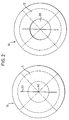
- Fig. 2 shows a view of the closure element 10 according to the invention from the Perspective A-A (left) and B-B (right) according to Fig. 1.
- the solid lines 2 correspond to the visible contours of the closure element 10, while the broken lines represent cut edges in the chosen perspective are not visible.
- Fig. 2 left shows the closure element 10 with the Wall 14 with the automatically closing slot-shaped incision 141 has a central portion 143.
- the cylindrical surfaces of the hollow cylinder are in Fig. 2 by the outermost solid and the openwork offset Line shown.
- Fig. 2 right shows the wall 14 opposite Wall 12. In this is the circular and central opening 121.
- Fig. 2 illustrates that the opening 121 and the central portion 143 of the slot-shaped incision 141 are aligned.
- the slit-shaped incision 141 is shown on the right in FIG. 2 as a partially broken line, since this is shown in the selected view is only visible within the opening 121.
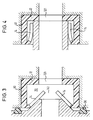
- FIG. 3 shows the closure element 10 according to the invention during a sterilization process.
- 3 introduced from the left of the sterilizer is introduced such that it first touches the wall 14 and at further insertion deforms the elastic wall 14 in such a way that the slit-shaped incision 141, which is closed when not in use, expands and forms an opening for the inflowing or outflowing sterilizing medium can be formed as a liquid, gas or vapor.
- the embodiment is sealed by means of a sterilization device located sealing ring 30, which receives the closure element 10 Seals the housing.
- the sterilization liquid now passes through the opening 141 into the cavity 20 of the closure element 10 and into the ring area, which extends to the sealing ring 30 abutting the housing.
- the wall 14 of the closure element 10 After passing of the slot-shaped incision 141 deformed into an opening reaches the Liquid through the opening 121 into the component to be sterilized, for example in a dialysis filter. After removal of the sterilizer connector at the end the process, the wall 14 of the closure element 10 is in its original Shape reshaped, causing the opening to close and re-open forms a slot-shaped incision 141. This now closes the sterilized one Component tightly, which for example causes leakage and dripping of sterilization liquid and on the other hand the penetration of unwanted Substances and germs is prevented.
- connection piece becomes like this through the slot-shaped incision 141 of the wall 14 until the end face of the connector on the cavity 20 of the closure element 10 adjacent side of the wall 12 rests sealingly.
- Diameter of the connector is the on both sides of the areas of the wall 14 in the direction of the slot-shaped incision 141 of the wall 12 curved, as can be seen from FIG. 4.
- the supply or discharge Liquid now passes through the opening of the connector and through the opening 121 of the wall 12 in or out of the connected component, for example a connected dialysis filter. Due to the tight closure of the Front side of the connector on the inside of the wall 12 is a tight and thus germ-free connection achieved. 4 also shows that with a correspondingly favorable coordination of connection piece and closure element a straightforward passage for the liquid is achieved, whereby the formation of unwanted dead zones can be largely avoided can.
- the connector is withdrawn, causing the areas of the wall 14 deform back into their original shape and, as shown in Fig. 2, again a tightly closing slot-shaped Form incision 141.
- FIG. 3 and Fig. 4 illustrate that neither the sterilization when the intended use of the invention Closure element 10 germs in the circuit or in the connected Component can reach.
- Another advantage is that the invention Closure element 10 from the corresponding housing recess easily can be removed, making simple and inexpensive replacement possible is. In this way, a hygienic and sterile connection of the to connecting components reached, and contamination of the liquids to be pumped avoided.
- FIG. 5 is a plan view of the second embodiment of the closure element 10 shown.
- the closure element 10 has a cylindrical shape, wherein in the front face shown in FIG. 5 the automatically closing slot-shaped Notch 141 of the wall 14 can be seen.
- the spring elements 145 arranged in the right and left of the slot-shaped incision 141 extending areas. These serve the radial tension forces in the transverse direction in the course of the spring element by reducing the cross-section of the wall 14 lower.
- Fig. 5 illustrates that the spring elements 145 are not completely, but part-circular extend around the slot-shaped incision 141 of the wall 14 and in the region 149 which extends in the longitudinal direction of the incision 141 are provided.
- This has the advantage that the radial force in Closing direction is increased, which is a particularly effective and germ-tight Closure of the incision 141 results.
- Such a design of the closure element with spring elements 145 thus leads to the fact that an improved sealing behavior of the cut 141 of the wall 14 results.
- the spring areas 145 can advantageously be designed such that when executed of the closure element 10 made of silicone according to the present Embodiment in the unloaded state, a pressure difference of +/- 0.25 bar is tolerable without the incision 141 losing its sealing effect.
- Cylinder jacket has the circumferential projection 131 in its end region. This serves to close the closure element 10 into a corresponding recess of the connecting piece 42 shown in Fig. 7 to lock or securely there fix.
- Fig. 7 shows in a longitudinal section the closure element 10 used in the Embodiment according to FIGS. 5 and 6.
- the closure element 10 is here on the protruding connection piece 42 placed and by means of the circumferential projection 131 locked.
- closure element 10 is designed such that its cylindrical surface forming the fastening means both is fitted on the outside as well as on the inside. Out of it it follows that the attached or inserted closure member 10 over the inner surface with the outer surface of a protruding connection piece 42 or over the outer surface with the inner surface of a socket-shaped connecting piece ensures a germ-tight seal.
Abstract
Description
- Fig. 1:
- einen Längsschnitt durch ein erfindungsgemäßes Verschlußelement gemäß einer ersten Ausführungsform sowie durch eine entsprechende Gehäuseaussparung zur Aufnahme des Verschlußelementes;
- Fig. 2:
- eine Ansicht des Verschlußelementes nach Fig. 1 gemäß Perspektive A-A (links) und Perspektive B-B (rechts);
- Fig. 3:
- einen Längsschnitt des eingesetzten Verschlußelementes nach Fig. 1 während eines Sterilisationsvorganges;
- Fig. 4:
- einen Längsschnitt des eingesetzten Verschlußelementes nach Fig. 1 während der bestimmungsgemäßen Benutzung;
- Fig. 5:
- eine Draufsicht auf ein erfindungsgemäßes Verschlußelement mit Federelementen gemäß einer zweiten Ausführungsform;
- Fig. 6:
- einen Längsschnitt des Verschlußelementes nach Fig. 5 gemäß der Linie A-A und
- Fig. 7:
- einen Längsschnitt des eingesetzten erfindungsgemäßen Verschlußelementes gemäß Fig. 5 unmittelbar vor der Verbindung mit einem Konnektionselement.
Claims (22)
- Verschlußelement (10) zum sterilen Verschluß von Anschlüssen (42), insbesondere von Anschlüssen (42) von Filtermodulen für die Dialyse, Hämo- oder Ultrafiltration,
dadurch gekennzeichnet,
daß das Verschlußelement (10) eine Wandung (14) umfaßt, die einen selbsttätig schließenden schlitzförmigen Einschnitt (141) aufweist, der im geschlossenen Zustand keimdicht abschließt, und daß Befestigungsmittel vorgesehen sind, die an die Wandung (14) angrenzen und mittels derer das Verschlußelement (10) mit einem Anschluß (42) verbindbar ist. - Verschlußelement (10) nach Anspruch 1, dadurch gekennzeichnet, daß das Verschlußelement (10) eine im wesentlichen zylindrische Gestalt aufweist, wobei die Befestigungsmittel durch die Zylinderfläche gebildet werden und der schlitzförmige Einschnitt (141) in einer der Stirnflächen (14) des Zylinders angeordnet ist.
- Verschlußelement (10) nach Anspruch 1 oder 2, dadurch gekennzeichnet, daß das Verschlußelement (10) symmetrisch ausgeführt ist.
- Verschlußelement (10) nach einem oder mehreren der Ansprüche 1-3, dadurch gekennzeichnet, daß der schlitzförmige Einschnitt (141) kreuz- oder sternförmig ausgeführt ist.
- Verschlußelement (10) nach einem oder mehreren der Ansprüche 1-4, dadurch gekennzeichnet, daß eine der den Einschnitt (141) aufweisenden Wandung (14) gegenüberliegende weitere Wandung (12) vorgesehen ist, die eine Öffnung (121) zum Durchtritt eines Fluids aufweist.
- Verschlußelement (10) nach Anspruch 5, dadurch gekennzeichnet, daß der mittlere Bereich des Einschnittes (141) und der Öffnung (121) miteinander fluchten.
- Verschlußelement (10) nach Anspruch 5 oder 6, dadurch gekennzeichnet, daß der sich um die Öffnung (121) der weiteren Wandung (12) erstreckende Bereich in einer im wesentlichen senkrecht zur Fügerichtung eines mit dem Anschluß (42) verbindbaren Konnektionselementes (50) verlaufenden Ebene angeordnet ist.
- Verschlußelement (10) nach einem oder mehreren der Ansprüche 1-7, dadurch gekennzeichnet, daß das Verschlußelement (10) einteilig ausgeführt ist.
- Verschlußelement (10) nach einem oder mehreren der Ansprüche 1-8, dadurch gekennzeichnet, daß die den Einschnitt (141) aufweisende Wandung (14) oder das gesamte Verschlußelement (10) aus Kunststoff bestehen.
- Verschlußelement (10) nach Anspruch 9, dadurch gekennzeichnet, daß der Kunststoff Silikon ist.
- Verschlußelement (10) nach einem oder mehreren der Ansprüche 1-10, dadurch gekennzeichnet, daß die den schlitzförmigen Einschnitt (141) aufweisende Wandung (14) des Verschlußelementes (10) ein in radialer Richtung wirkendes Federelement (145) aufweist.
- Verschlußelement (10) nach Anspruch 11, dadurch gekennzeichnet, daß das Federelement (145) aus abwechselnd oder einzelnen auf der Ober- und/oder Unterseite der Wandung (14) angeordneten Vertiefungen (147) gebildet wird.
- Verschlußelement (10) nach Anspruch 12, dadurch gekennzeichnet, daß die Vertiefungen (147) teilkreisförmig ausgeführt sind.
- Verschlußelement (10) nach einem oder mehreren der Ansprüche 11-13, dadurch gekennzeichnet, daß in den sich in Längsrichtung des Einschnittes (141) erstreckenden Bereichen (149) der Wandung (14) kein Federelement vorgesehen ist.
- Verschlußelement (10) nach einem oder mehreren der Ansprüche 1-14, dadurch gekennzeichnet, daß der schlitzförmige Einschnitt (141) des Verschlußelementes (10) bis zu einer Druckdifferenz von +/- 0,25 bar keimdicht schließt.
- Verwendung eines Verschlußelementes (10) nach einem oder mehreren der Ansprüche 1-15 für den sterilen Verschluß von Anschlüssen medizinischer Artikel.
- Verwendung nach Anspruch 16, dadurch gekennzeichnet, daß der medizinische Artikel ein Filtermodul für die Dialyse, Hämo- oder Ultrafiltration ist und das Verschlußelement (10) für die Inline-Sterilisation des Filtermoduls verwendet wird.
- Verwendung nach Anspruch 16 oder 17, dadurch gekennzeichnet, daß das Befestigungsmittel des Verschlußelementes (10) derart ausgeführt ist, daß das Verschlußelement (10) auf vorstehende oder in buchsenförmige Anschlüsse auf- bzw. einsetzbar ist.
- Medizinischer Artikel mit einem oder mehreren Anschlüssen zur Zu- und/oder Abführung eines Fluids,
dadurch gekennzeichnet,
daß mindestens ein Anschluß mit einem Verschlußelement (10) nach einem oder mehreren der Ansprüche 1-15 versehen ist. - Medizinischer Artikel nach Anspruch 19, dadurch gekennzeichnet, daß der medizinische Artikel ein Filtermodul für die Dialyse, Hämo- oder Ultrafiltration ist.
- Medizinischer Artikel nach Anspruch 19 oder 20, dadurch gekennzeichnet, daß das Verschlußelement (10) derart ausgeführt ist, daß die Innenfläche des Verschlußelementes (10) mit der Außenfläche eines vorstehenden Anschlusses (42) oder die Außenfläche des Verschlußelementes (10) mit der Innenfläche eines buchsenförmigen Anschlusses keimdicht verbunden sind.
- Medizinischer Artikel nach einem oder mehreren der Ansprüche 19-21, dadurch gekennzeichnet, daß mindestens zwei Anschlüsse des medizinischen Artikels mit einem Verschlußelement nach einem oder mehreren der Ansprüche 1-15 versehen sind.
Applications Claiming Priority (2)
| Application Number | Priority Date | Filing Date | Title |
|---|---|---|---|
| DE19852557 | 1998-11-13 | ||
| DE19852557A DE19852557C2 (de) | 1998-11-13 | 1998-11-13 | Verschlußelement |
Publications (3)
| Publication Number | Publication Date |
|---|---|
| EP1000632A2 true EP1000632A2 (de) | 2000-05-17 |
| EP1000632A3 EP1000632A3 (de) | 2000-11-08 |
| EP1000632B1 EP1000632B1 (de) | 2005-06-08 |
Family
ID=7887797
Family Applications (1)
| Application Number | Title | Priority Date | Filing Date |
|---|---|---|---|
| EP99120405A Expired - Lifetime EP1000632B1 (de) | 1998-11-13 | 1999-10-13 | Verschlusselement |
Country Status (5)
| Country | Link |
|---|---|
| US (2) | US6419825B1 (de) |
| EP (1) | EP1000632B1 (de) |
| JP (1) | JP4630411B2 (de) |
| DE (2) | DE19852557C2 (de) |
| ES (1) | ES2244134T3 (de) |
Cited By (1)
| Publication number | Priority date | Publication date | Assignee | Title |
|---|---|---|---|---|
| DE102015102719A1 (de) | 2015-02-25 | 2016-08-25 | B. Braun Avitum Ag | Konnektor für einen Dialysator |
Families Citing this family (27)
| Publication number | Priority date | Publication date | Assignee | Title |
|---|---|---|---|---|
| US7198611B2 (en) | 2002-02-11 | 2007-04-03 | Baxter International Inc. | Dialysis connector and cap having an integral disinfectant |
| US7232419B2 (en) | 2002-02-11 | 2007-06-19 | Baxter International Inc. | Enclosure with cam action snap release |
| US8377039B2 (en) | 2002-10-04 | 2013-02-19 | Nxstage Medical, Inc. | Injection site for male luer or other tubular connector |
| US7025744B2 (en) * | 2002-10-04 | 2006-04-11 | Dsu Medical Corporation | Injection site for male luer or other tubular connector |
| US6915919B2 (en) * | 2002-11-21 | 2005-07-12 | American Bio Medica Corporation | Container closure cap with self-sealing slot |
| US7217033B2 (en) * | 2004-05-13 | 2007-05-15 | Fres-Co System Usa, Inc. | Aseptic packaging for foods and systems and methods for aseptically packaging foods |
| JP4514537B2 (ja) * | 2004-07-16 | 2010-07-28 | 三洋電機株式会社 | ホースの連結構造および排泄物処理装置 |
| WO2008050655A1 (fr) * | 2006-10-17 | 2008-05-02 | Jms Co., Ltd. | Organe de communication et conteneur médical utilisant cet organe |
| US7736328B2 (en) | 2007-07-05 | 2010-06-15 | Baxter International Inc. | Dialysis system having supply container autoconnection |
| JP2009089887A (ja) * | 2007-10-09 | 2009-04-30 | Nikkiso Co Ltd | 血液浄化装置 |
| US8251263B2 (en) | 2008-03-24 | 2012-08-28 | Mary Kay Inc. | Container caps and systems |
| KR101027368B1 (ko) | 2008-05-06 | 2011-04-11 | 천도철 | 유수분리기 |
| MX2011000976A (es) | 2008-07-24 | 2011-07-29 | Mary Kay Inc | Tapas y sistemas para contenedor. |
| US9555180B2 (en) | 2008-11-21 | 2017-01-31 | Baxter International Inc. | Systems and methods for removing air from the patient's peritoneal cavity |
| US8753515B2 (en) | 2009-12-05 | 2014-06-17 | Home Dialysis Plus, Ltd. | Dialysis system with ultrafiltration control |
| US8501009B2 (en) | 2010-06-07 | 2013-08-06 | State Of Oregon Acting By And Through The State Board Of Higher Education On Behalf Of Oregon State University | Fluid purification system |
| WO2013052680A2 (en) | 2011-10-07 | 2013-04-11 | Home Dialysis Plus, Ltd. | Heat exchange fluid purification for dialysis system |
| US9051066B1 (en) | 2014-02-07 | 2015-06-09 | Tinnus Enterprises, Llc | System and method for filling containers with fluids |
| WO2015168280A1 (en) | 2014-04-29 | 2015-11-05 | Outset Medical, Inc. | Dialysis system and methods |
| US10828484B2 (en) | 2015-08-21 | 2020-11-10 | Medline Industries, Inc. | Disinfecting cap |
| US10357579B2 (en) * | 2015-10-05 | 2019-07-23 | Texas Medical Group SOPARFI S.a.r.l. | Device port cleaner |
| US10576261B2 (en) | 2015-12-11 | 2020-03-03 | Turnstone Technologies, LLC | Device male port cleaner |
| WO2017193073A1 (en) | 2016-05-06 | 2017-11-09 | Gambro Lundia Ab | Systems and methods for peritoneal dialysis having point of use dialysis fluid preparation including mixing and heating therefore |
| US10493370B2 (en) | 2016-06-21 | 2019-12-03 | Tinnus Enterprises, Llc | System and method for filling containers with fluids and sealing the filled containers |
| EP3500317B1 (de) | 2016-08-19 | 2022-02-23 | Outset Medical, Inc. | Peritonealdialysesystem und -verfahren |
| DE202016008234U1 (de) | 2016-12-21 | 2017-05-04 | Alpha Plan Gmbh | Zwischenelement zur Sterilisation, Sanitisierung, Reinigung und/oder Keimreduktion von Vorrichtungen zum Testen, Spülen und/oder Befüllen von wenigstens zwei Anschlüsse aufweisenden Gegenständen, Verwendung des Zwischenelements und Vorrichtung |
| US10099048B2 (en) | 2017-03-10 | 2018-10-16 | Turnstone Technologies, LLC | Device port cleaner |
Citations (1)
| Publication number | Priority date | Publication date | Assignee | Title |
|---|---|---|---|---|
| EP0352540A2 (de) | 1988-07-28 | 1990-01-31 | Fresenius AG | Verschlusskappe für Dialysatoren |
Family Cites Families (22)
| Publication number | Priority date | Publication date | Assignee | Title |
|---|---|---|---|---|
| US4143853A (en) * | 1977-07-14 | 1979-03-13 | Metatech Corporation | Valve for use with a catheter or the like |
| US4197848A (en) * | 1978-01-06 | 1980-04-15 | Baxter Travenol Laboratories, Inc. | Closed urinary irrigation site |
| DE2817102C2 (de) * | 1978-04-19 | 1985-01-24 | Dr. Eduard Fresenius, Chemisch-pharmazeutische Industrie KG, 6380 Bad Homburg | Anschlußstück für Kunststoffkanülen oder Venenkatheter |
| DE2818146A1 (de) * | 1978-04-26 | 1979-11-08 | Fresenius Chem Pharm Ind | Verschlussteil fuer sterile medizinische apparate |
| US4402420A (en) * | 1981-12-07 | 1983-09-06 | Extracorporeal Medical Specialties, Inc. | Dual function port cap |
| US4475548A (en) * | 1982-06-01 | 1984-10-09 | Rudolph Muto | Fitting for endotracheal tube apparatus and method of making the fitting |
| US4511359A (en) * | 1982-09-29 | 1985-04-16 | Manresa, Inc. | Sterile connection device |
| DE3322003A1 (de) * | 1983-06-18 | 1984-12-20 | Theophil 4230 Wesel Richert | Rueckschlag-lippenventil "universal" fuer fassbieranstich |
| US4769017A (en) * | 1985-04-04 | 1988-09-06 | Fath John J | Self-sealing infusion manifold and catheter connector |
| US4929235A (en) * | 1985-07-31 | 1990-05-29 | Universal Medical Instrument Corp. | Self-sealing percutaneous tube introducer |
| IT1197528B (it) * | 1986-10-30 | 1988-11-30 | O D L Srl | Sistema di lavaggio per impianti di spillatura a bilanciamento di pressione automatico con possibilita' di cambio semiautomatico dei fusti |
| EP0544653B1 (de) * | 1988-01-25 | 1996-06-05 | Baxter International Inc. | Injektionsstelle |
| US4960412A (en) * | 1988-04-15 | 1990-10-02 | Universal Medical Instrument Corp. | Catheter introducing system |
| DE4303026C2 (de) * | 1992-04-02 | 1995-05-24 | Kuehlmann Manfred | Trokar für minimal invasive Chirurgie |
| CA2093754C (en) * | 1992-04-24 | 1996-08-13 | David T. Green | Valve assembly for introducing instruments into body cavities |
| US5328041A (en) * | 1993-06-30 | 1994-07-12 | Abbott Laboratories | Two piece stopper for blunt fluid connector |
| DE69332209T2 (de) * | 1993-12-01 | 2002-12-12 | Applied Med Resources | Trocar mit einem universellen dichtungsschutz |
| US5474544A (en) * | 1994-05-25 | 1995-12-12 | Lynn; Lawrence A. | Luer-receiving medical valve |
| US5643190A (en) * | 1995-01-17 | 1997-07-01 | Medisystems Technology Corporation | Flow-through treatment device |
| US5957898A (en) * | 1997-05-20 | 1999-09-28 | Baxter International Inc. | Needleless connector |
| US6039718A (en) * | 1998-01-20 | 2000-03-21 | Bracco Research Usa | Multiple use universal connector |
| US5921419A (en) * | 1998-05-04 | 1999-07-13 | Bracco Research Usa | Universal stopper |
-
1998
- 1998-11-13 DE DE19852557A patent/DE19852557C2/de not_active Expired - Lifetime
-
1999
- 1999-10-13 DE DE59912141T patent/DE59912141D1/de not_active Expired - Lifetime
- 1999-10-13 ES ES99120405T patent/ES2244134T3/es not_active Expired - Lifetime
- 1999-10-13 EP EP99120405A patent/EP1000632B1/de not_active Expired - Lifetime
- 1999-11-15 US US09/441,182 patent/US6419825B1/en not_active Expired - Lifetime
- 1999-11-15 JP JP32454999A patent/JP4630411B2/ja not_active Expired - Lifetime
-
2002
- 2002-01-18 US US10/052,768 patent/US6858137B2/en not_active Expired - Lifetime
Patent Citations (1)
| Publication number | Priority date | Publication date | Assignee | Title |
|---|---|---|---|---|
| EP0352540A2 (de) | 1988-07-28 | 1990-01-31 | Fresenius AG | Verschlusskappe für Dialysatoren |
Cited By (3)
| Publication number | Priority date | Publication date | Assignee | Title |
|---|---|---|---|---|
| DE102015102719A1 (de) | 2015-02-25 | 2016-08-25 | B. Braun Avitum Ag | Konnektor für einen Dialysator |
| EP3061489A2 (de) | 2015-02-25 | 2016-08-31 | B. Braun Avitum AG | Konnektor für einen dialysator |
| US10058692B2 (en) | 2015-02-25 | 2018-08-28 | B. Braun Avitum Ag | Connector for dialyzer |
Also Published As
| Publication number | Publication date |
|---|---|
| EP1000632A3 (de) | 2000-11-08 |
| US6419825B1 (en) | 2002-07-16 |
| DE19852557A1 (de) | 2000-05-18 |
| US6858137B2 (en) | 2005-02-22 |
| DE59912141D1 (de) | 2005-07-14 |
| JP2000140099A (ja) | 2000-05-23 |
| US20020104791A1 (en) | 2002-08-08 |
| DE19852557C2 (de) | 2002-11-07 |
| ES2244134T3 (es) | 2005-12-01 |
| JP4630411B2 (ja) | 2011-02-09 |
| EP1000632B1 (de) | 2005-06-08 |
Similar Documents
| Publication | Publication Date | Title |
|---|---|---|
| EP1000632B1 (de) | Verschlusselement | |
| DE4129782C1 (de) | ||
| EP1350476B1 (de) | Trokarhülse | |
| EP0966985B1 (de) | Konnektorelement mit Verschlussteil insbesondere zum Verbinden von medizinischen Schläuchen, Kanülen und Kathetern | |
| DE3309918C2 (de) | Saug- und Spülvorrichtung | |
| DE60016785T2 (de) | Vaskulare einführhülse und damit zu verwendendes hämostatisches ventil | |
| DE10127823C1 (de) | Verschluss für eine Medikamentenflasche sowie Verfahren zu dessen Herstellung | |
| DE102006046428A1 (de) | Sternumverschluss | |
| DE10121356B4 (de) | Ventilanordnung für chirurgische Instrumente und Ventilkorb zur Aufnahme der Ventilanordung | |
| DE3513204A1 (de) | Zweibeutel-system fuer die peritonealdialyse sowie konnektor hierfuer | |
| EP1684847B1 (de) | Konnektor für dialyseport | |
| DE19828650A1 (de) | Konnektorelement | |
| EP0648097A1 (de) | Verfahren und vorrichtung zur reinigung ärztlicher instrumente. | |
| DE3825573A1 (de) | Verschlusskappe fuer dialysatoren | |
| EP0660727B1 (de) | Sicherheitsverbinder für die infusionstherapie | |
| DE69920324T2 (de) | Abgedichtete Transportvorrichtung mit integrietrer Ultraviolettdekontaminationseinrichtung | |
| EP0171520B1 (de) | Kräuterpackung | |
| EP0374280B1 (de) | Einmalfilterhalter | |
| EP2105106B1 (de) | Medizinische Reinigungsvorrichtung zum Reinigen von innenliegenden Oberflächen | |
| EP1059984B1 (de) | Tray | |
| DE20315612U1 (de) | Chirurgisches Verbindungselement | |
| EP0592641B1 (de) | Sicherheitsverschluss für behälteranschlüsse | |
| DE102011010149A1 (de) | Stopfen zum Verschließen und/oder Abdichten einer Öffnung in einem medizintechnischen Gerät, Behandlungsvorrichtung sowie Verfahren | |
| DE10114978B4 (de) | Autoklav-Sterilisationsanlage | |
| EP4048202A1 (de) | Injektor für ein einführen einer intraokularlinse |
Legal Events
| Date | Code | Title | Description |
|---|---|---|---|
| PUAI | Public reference made under article 153(3) epc to a published international application that has entered the european phase |
Free format text: ORIGINAL CODE: 0009012 |
|
| AK | Designated contracting states |
Kind code of ref document: A2 Designated state(s): DE ES FR GB IT |
|
| AX | Request for extension of the european patent |
Free format text: AL;LT;LV;MK;RO;SI |
|
| PUAL | Search report despatched |
Free format text: ORIGINAL CODE: 0009013 |
|
| AK | Designated contracting states |
Kind code of ref document: A3 Designated state(s): AT BE CH CY DE DK ES FI FR GB GR IE IT LI LU MC NL PT SE |
|
| AX | Request for extension of the european patent |
Free format text: AL;LT;LV;MK;RO;SI |
|
| 17P | Request for examination filed |
Effective date: 20010329 |
|
| AKX | Designation fees paid |
Free format text: DE ES FR GB IT |
|
| 17Q | First examination report despatched |
Effective date: 20031007 |
|
| GRAP | Despatch of communication of intention to grant a patent |
Free format text: ORIGINAL CODE: EPIDOSNIGR1 |
|
| GRAS | Grant fee paid |
Free format text: ORIGINAL CODE: EPIDOSNIGR3 |
|
| GRAA | (expected) grant |
Free format text: ORIGINAL CODE: 0009210 |
|
| AK | Designated contracting states |
Kind code of ref document: B1 Designated state(s): DE ES FR GB IT |
|
| REG | Reference to a national code |
Ref country code: GB Ref legal event code: FG4D Free format text: NOT ENGLISH |
|
| REF | Corresponds to: |
Ref document number: 59912141 Country of ref document: DE Date of ref document: 20050714 Kind code of ref document: P |
|
| GBT | Gb: translation of ep patent filed (gb section 77(6)(a)/1977) |
Effective date: 20050804 |
|
| REG | Reference to a national code |
Ref country code: ES Ref legal event code: FG2A Ref document number: 2244134 Country of ref document: ES Kind code of ref document: T3 |
|
| ET | Fr: translation filed | ||
| PLBE | No opposition filed within time limit |
Free format text: ORIGINAL CODE: 0009261 |
|
| STAA | Information on the status of an ep patent application or granted ep patent |
Free format text: STATUS: NO OPPOSITION FILED WITHIN TIME LIMIT |
|
| 26N | No opposition filed |
Effective date: 20060309 |
|
| REG | Reference to a national code |
Ref country code: FR Ref legal event code: PLFP Year of fee payment: 18 |
|
| REG | Reference to a national code |
Ref country code: FR Ref legal event code: PLFP Year of fee payment: 19 |
|
| REG | Reference to a national code |
Ref country code: FR Ref legal event code: PLFP Year of fee payment: 20 |
|
| PGFP | Annual fee paid to national office [announced via postgrant information from national office to epo] |
Ref country code: IT Payment date: 20180919 Year of fee payment: 20 Ref country code: FR Payment date: 20180920 Year of fee payment: 20 |
|
| PGFP | Annual fee paid to national office [announced via postgrant information from national office to epo] |
Ref country code: GB Payment date: 20180925 Year of fee payment: 20 |
|
| PGFP | Annual fee paid to national office [announced via postgrant information from national office to epo] |
Ref country code: DE Payment date: 20180819 Year of fee payment: 20 |
|
| PGFP | Annual fee paid to national office [announced via postgrant information from national office to epo] |
Ref country code: ES Payment date: 20181105 Year of fee payment: 20 |
|
| REG | Reference to a national code |
Ref country code: DE Ref legal event code: R071 Ref document number: 59912141 Country of ref document: DE |
|
| REG | Reference to a national code |
Ref country code: GB Ref legal event code: PE20 Expiry date: 20191012 |
|
| PG25 | Lapsed in a contracting state [announced via postgrant information from national office to epo] |
Ref country code: GB Free format text: LAPSE BECAUSE OF EXPIRATION OF PROTECTION Effective date: 20191012 |
|
| REG | Reference to a national code |
Ref country code: ES Ref legal event code: FD2A Effective date: 20220126 |
|
| PG25 | Lapsed in a contracting state [announced via postgrant information from national office to epo] |
Ref country code: ES Free format text: LAPSE BECAUSE OF EXPIRATION OF PROTECTION Effective date: 20191014 |