EP1002455A2 - Process and device for adjusting a sensor unit relative to a field working machine - Google Patents
Process and device for adjusting a sensor unit relative to a field working machine Download PDFInfo
- Publication number
- EP1002455A2 EP1002455A2 EP99122102A EP99122102A EP1002455A2 EP 1002455 A2 EP1002455 A2 EP 1002455A2 EP 99122102 A EP99122102 A EP 99122102A EP 99122102 A EP99122102 A EP 99122102A EP 1002455 A2 EP1002455 A2 EP 1002455A2
- Authority
- EP
- European Patent Office
- Prior art keywords
- sensor unit
- unit
- adjusting device
- display
- support arm
- Prior art date
- Legal status (The legal status is an assumption and is not a legal conclusion. Google has not performed a legal analysis and makes no representation as to the accuracy of the status listed.)
- Ceased
Links
Images


Classifications
-
- A—HUMAN NECESSITIES
- A01—AGRICULTURE; FORESTRY; ANIMAL HUSBANDRY; HUNTING; TRAPPING; FISHING
- A01D—HARVESTING; MOWING
- A01D41/00—Combines, i.e. harvesters or mowers combined with threshing devices
- A01D41/12—Details of combines
- A01D41/127—Control or measuring arrangements specially adapted for combines
- A01D41/1278—Control or measuring arrangements specially adapted for combines for automatic steering
-
- A—HUMAN NECESSITIES
- A01—AGRICULTURE; FORESTRY; ANIMAL HUSBANDRY; HUNTING; TRAPPING; FISHING
- A01B—SOIL WORKING IN AGRICULTURE OR FORESTRY; PARTS, DETAILS, OR ACCESSORIES OF AGRICULTURAL MACHINES OR IMPLEMENTS, IN GENERAL
- A01B69/00—Steering of agricultural machines or implements; Guiding agricultural machines or implements on a desired track
- A01B69/007—Steering or guiding of agricultural vehicles, e.g. steering of the tractor to keep the plough in the furrow
Definitions
- the invention relates to a method for adjusting on a Field machine attached sensor unit according to the generic term of claim 1 and an adjusting device according to Preamble of claim 6.
- US Pat. No. 3,991,618 discloses a device for detection a field processing edge in which a sensor unit has a plurality of sensors in the area of the soil spread over several places on a harvesting machine are attached to the same.
- the sensors are on the one hand at a front end and on the other a rear end of the harvester.
- the sensors are designed as touching sensors with a sensor arm, the presence or absence of a crop detected.
- the sensor signal generated by the sensors acts on a steering control unit, which is an automatic Moving the harvester along the field cultivation edge enables.
- a disadvantage of the known device is that a plurality of arranged in different locations Sensors are provided so that the device is relatively expensive. As a result of the mechanical stress the sensors are subject to undesirable wear. Due to the arrangement of the sensors near the ground there is a risk that the sensors may be affected by unforeseen external influences can be damaged.
- the object of the present invention is therefore a method for adjusting one attached to a field machine Specify sensor unit such that the adjustment position of the Sensor unit easily recognized and set can be.
- the method according to the invention has a solution to this problem the features of claim 1.
- the particular advantage of the method according to the invention is that the adjustment of the adjustment position of the sensor unit in a simple way, including for others Recognized the purposes of the electronic means used and can be set.
- the sensor unit Assigned steep means by means of which the sensor unit in adjusted in the horizontal and / or vertical direction can be.
- These control devices are operated by a central Processing unit applied. In this processing unit becomes the sensor signal emitted by the sensor unit evaluated and depending on it the sensor unit moves on until it detects a reference point or a reference line reaches an adjustment position Has.
- a display unit is used to check the adjustment position of the Display field or the arrangement of the display elements of the display unit are so on the relative location of the field machine matched to the field processing edge that the adjustment position by matching one by the sensor signal controlled display element to a predetermined ID is recognized.
- the activated display elements signal the current detected by the sensor unit Place of the floor.
- the identifier signals that by the Reference position or reference line marked adjustment position the sensor unit.
- the identifier is preferably in one central area of the display unit, so that the adjustment position is easily recognizable and verifiable.
- Another object of the present invention is an adjustment device specify for a sensor unit that is simple and reliable permanent determination of the sensor unit with respect to a reference point of the field machine enables.
- the adjusting device according to the invention has the features of claim 6.
- the advantage of the adjustment device according to the invention is in particular in that by means of an optical display unit the adjustment of the sensor unit on the field machine is easy to use.
- the Display unit of several display elements arranged in a row on, with at least two rows of display elements are spaced from each other.
- the target position of the sensor unit is given if the ends are facing each other Display elements of the rows light up.
- the debit position the sensor unit is thus characterized by the display elements indicated that the illuminated display elements one have the smallest possible distance from each other.
- each result two motion components, each by a series of Display elements are symbolized.
- the position of the field machine can be adjusted.
- the axial Arrangement of the holes or fasteners on the opposite ends of the U-shaped neck is one clear and reliable adjustment around this formed swivel axis possible. If the sensor unit has a U-shaped approach, this can be together with the holding arm form a cavity in which the sensor unit stored and protected from the weather.
- the adjusting device coaxial to an upright support arm the harvester rotatably supported, at least one Row of display elements in the axial direction Extend arm. This makes the assignment to the direction of movement and thus reading the display unit facilitated.
- the adjusting device Sensor unit on one extending transversely to the direction of travel Holding arm held. When the sensor unit is released these are simultaneously shifted in a straight line along the holding arm and twisted around it.
- the device according to the invention can be used to detect Edges are used during field processing. she can be used on the one hand on harvesting machines to identify a field processing edge and on the other hand for recognition on tractors a field processing edge can be used, see Figure 1 and Figure 5.
- a sensor unit 1 attached to a combine 2 as a self-propelled harvester is at the front in the direction of travel attached to a cutting unit 3 of the combine 2 on the left.
- the combine 2 has a Reel 4, by means of which the crop 5 in the direction a feed roller 9 is promoted.
- the reel 4 is over a reel support arm 7 pivotally connected.
- a knife 8 is arranged in a lower one.
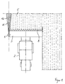
- Support arm 10 protruding above is arranged at its free end the sensor unit 1 is attached.
- the support arm 10 is with respect to a vertical at an acute angle inclined at the front so that the adjustment of the sensor unit 1 in the direction of a field processing edge 12 facilitated becomes.
- the support arm 10 has such a length that the sensor unit 1 over the reel 4 the field processing edge 12 can detect.
- the sensor unit 1 is in the direction of travel of the combine harvester 2 aligned and has a detection area to be scanned 11 on.
- the sensor unit 1 has a laser sensor as an optical sensor on that is set to a given distance is.
- the previously set distance in an area can be between 12 and 16 m, preferably 14 m, depends on the steering behavior and the driving speed of the combine harvester 2. Is the sensor unit 1 towards one long distance is set, a change in the field processing edge 12 recognized too early, with the effect that the steering of the combine 2 responds too early and thus there is an overload. If the distance is too short has been set, a deviation of the field processing edge 12 recognized too late, so that the steering of the Combine 2 cannot respond in time.
- a prerequisite for correct adjustment is that the combine harvester 2 in the direction of travel and parallel to that provided Field processing edge 12 is arranged.
- the sensor unit 1 can start position on the field processing edge 12 can be adjusted.
- As a reference point for the adjustment of the sensor unit 1 an existing one Field processing edge 12 or edge or a special designated point of the combine harvester 2 itself. At Providing a reference point on the combine 2 is make sure that a corresponding positive guidance is provided which is the sensor unit from the adjustment position spends in the operating position.
- the adjustment device described below is oriented a field processing edge 12.
- the adjustment device enables improved header utilization, because after the sensor unit 1 has been adjusted, the combine harvester 2 automatically with the side edge of the Cutting unit 3 along the detected field processing edge 12 is steered. This is done by the adjustment Cutting with optimal use of the cutting width.
- the sensor unit 1 is on a frame-like u-shaped Attachment 13 attached, which extends downwards opening. Free ends 14 of the projection 13 point coaxially to one another aligned holes 15, in the respective fasteners 16 for screwing to the support arm 10 attached further u-shaped approach 17 can be engaged are.
- the approach 17 of the support arm 10 has upright tabs 18 on, with holes that go to holes 15 of the approach 13 are cursed.
- the approaches 13 and 17 are each on their Ends by the screws 16 with each other connected.
- By loosening a nut 19 at the ends 14 can the sensor unit 1 by a running through the holes 15 Pivot axis 20 can be pivoted. This makes an adjustment allows the sensor unit 1 in a vertical plane.
- the level is the U-shaped extension 17 by means of a screw connection 21 attached to the support arm 10.
- the screw connection 21 extends in the axial direction of the support arm 10 and allows twisting when in a loose position of the U-shaped projection 17 in the circumferential direction of the support arm 10.
- the U-shaped neck 13 of the Sensor unit 1 which screws 16 to the support arm 10 are set, moved.
- the orientation of the sensor unit 1 can be actuated the fastening means 16 on the one hand and the screw connection 21 on the other hand independently in the horizontally and in the vertical direction. This simplifies the adjustment because these adjustment steps are carried out one after the other can be made.
- the display unit 23 has a display field 24 with four rows of display elements 25 with a right angle of two rows of display elements 25 is formed. Each row consists of four display elements 25, each designed as light emitting diodes (LED) are.
- the display elements 25 run on a common one Center point 26, which is a target point for the Adjustment of the sensor unit 1 forms. The adjustment is correct made when each facing the center 26 end display elements 25 light up.
- the display field 24 is designed in the manner of a telescopic sight and therefore self-explanatory for the operator.
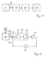
- a sensor signal 28 delivered by the sensor unit 1 is sent to a processing unit while the combine harvester 2 is traveling 29 transferred.
- This is preferably as trained electronic control unit and has a steering program that acts on a steering control unit 30.
- the steering control unit 30 has control valves by means of a steering cylinder 31 is actuated. As shown in Figure 8 can be seen, the sensor signal 28 can thus be used for control purposes of the steering cylinder 31 can be used.
- the sensor signal 28 can also be used to control the Steering cylinder 31 are used, see Figure 9. About this The purpose of this is the sensor signal 28 in the processing unit 29 processed according to a predetermined steering program.
- a target value is located at the output of the processing unit 29 32, which is given to a comparator 33. Find here a comparison with an actual value 34 for the steering angle instead of.
- the so-called control difference is sent to the input given a controller 35, preferably as a digital Regulator is formed.
- the output signal of controller 35 acts on one or more valves 36 that control the steering cylinder 31 taxes.
- the current steering angle of the steering cylinder 31 is detected and by means of a converter 37 which have a transmitter or an analog / digital converter can be transmitted as actual value 34 to the comparison point 33.
- the regulator 35 and the valve 36 form a part a steering control unit 50. It enables the steering cylinder automatically to that of the processing unit 29 predetermined target angle is regulated. This will enables an automatic harvesting journey, with recognition the crop edge by means of the sensor unit 1 the harvesting process reliable and time-saving with optimal utilization the cutting width of the cutting unit 3 performed becomes. By tuning the sensor unit 1 to the left edge of the cutting unit 3 can the crop edge 12 precisely recognized and the crop cut short become.
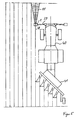
- the sensor unit 1 also for recognizing one by a Furrow formed field edge 38 can be used.
- the Field edge 38 forms the processing edge and can due to different height recognized on both sides of the edge 38 become.
- the sensor unit 1 is on a holding arm 39 mounted on a tractor or agricultural tractor 40, the arm 39 in front of the tractor 40 transversely extends to the direction of travel or to the field edge 38.
- the sensor unit 1 is arranged vertically above the field edge 38 and aligned with this.
- the tractor 40 pulls you Plow 41 after you.
- the display unit 23 is arranged in a driver's cabin and serves to check an automatic adjustment, which, for example, by actuating a Switch can be started by the driver.
- the automatic adjustment takes place through processing and evaluation of the sensor signal generated by the sensor unit 1. This can be done using an electrical cable or wirelessly to the central processing unit 29 of the agricultural tractor 40 are transmitted. In the processing unit 29 becomes the current sensor signal that a particular one Symbolizes the location of the scanned bottom 6, processed. It is necessary that the tractor 40 parallel is positioned to the rim edge 38. After alignment the sensor unit 1 to the field edge 38, the sensor unit 1 or the sensor aligned parallel to the field edge 38 is or has a predetermined zero position the sensor unit 1 assumed the desired adjustment position. The sensor unit 1 can now be fixed in this position become. This adjustment position is determined by a match the lighting up symbolizing the current position of the sensor unit 1 Display element 25 with a predetermined identifier checked. This identifier is preferably in the center 26 of the display unit 23. Depending from the now set position of the sensor unit 1 generates a straight-ahead signal that acts as a reference variable for the automatic steering of the tractor 40 serve can.
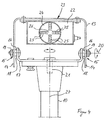
- the combine harvester 2 can use one of two ultrasonic sensors 42 formed sensor unit 43 equipped his.
- the sensor unit 43 is on one of front the sensor arm 44 projecting from the cutting unit 3 is movably mounted.
- the sensor support arm 44 is connected to the Cutting unit 3 connected and can be adjusted via a support arm height 45 from an operating position shown in FIG. 6 be pivoted into a lower transport position.
- Those corresponding to the first embodiment Components have the same reference numbers.
- the sensor unit is different from the first exemplary embodiment 43 on a cross arm to the direction of travel 44 hinged bracket 46 attached.
- This arm 46 encompasses the sensor unit 43 with a clip-like one Fastening element 47 that is designed as a clamp and by means of a screw connection 48 on the holding arm 46 is connectable.
- This type of fastening advantageously that the sensor unit 1 quickly in the adjustment position is feasible.
- the sensor unit 43 can aligned simultaneously in the horizontal and vertical directions become.
- the holding arm 46 forms the pivot axis for the orientation in the vertical direction. By moving the sensor unit 43 along the holding arm 46 becomes the alignment the sensor unit 43 causes in the horizontal direction.
- the sensor unit 43 has a first ultrasonic sensor 42, which in the direction of travel along the crop edge 12 is aligned and a second ultrasonic sensor 42 ' on that at an acute angle to the first ultrasonic sensor 42 stands and aligned with the crop 5 itself becomes.
- the ultrasonic sensors 42, 42 ' are inclined in this way trained towards the bottom 6 that their transmission signal in one Distance of more than four meters hits the floor 6. Due to the different orientation of the ultrasonic sensors 42, 42 'can be determined by the ratio of the respective Echo signals the field processing edge 12 are detected.
- the sensor signal thus formed for control or regulation the steering angle of a steering system of the combine harvester 2 be used.
- the adjustment of the ultrasonic sensors 42, 42 ' is carried out by individual display elements 49, which are designed as light-emitting diodes are displayed.
- individual display elements 49 For adjustment in the vertical plane are an upper on a side wall of the sensor unit 43 Display element 49 'and a lower display element 49' 'arranged.
- the sensor unit 43 is too far apart set to floor 6, the upper display element lights up 49 'in red color. Is the sensor unit 43 on one set too close to floor 6, lights up the lower display element 49 '' in red color. Is the sensor unit 43 at a correct distance from the floor 6 the upper and lower display elements light up 49 ', 49' 'in green color.
- a hysteresis circuit integrated so an undesirable Flashing of the display elements 49 ', 49' 'is avoided.
- the sensor unit 43 in the horizontal direction is another display element, not shown provided that when aligning the first ultrasonic sensor 42 lights up on the crop edge 12 in green color.
- the horizontal orientation is only in Exceptional cases required. It can be factory set be made as they depend on the dimensions of the cutting unit 3 must be coordinated. Because the cutting unit 3 forms with its left cutting edge a requirement for the through the same crop edge to be effected 12. It is therefore sufficient usually from that the sensor unit 43 in horizontal Direction is aligned to the cutting unit 3. Thereby, that the second ultrasonic sensor 42 'completely on the crop 5 is directed, can be a unique in a simple manner Sensor signal for the detection of the crop edge 12 generated become. The further processing of the sensor signal can in the first embodiment described above appropriate way.
- the processing unit 29 can be used to Remote control to operate the support arm height adjustment 45.
- Sensor unit 43 can be adjusted in the vertical direction.
- the height is therefore dependent on the crop or Grain height adjustable. It is essential that the sensor set to a certain predetermined distance range becomes.
- the support arm height adjustment 45 is preferred designed as a pressure-actuated cylinder and can be controlled electrically.
- the display unit 23 by one in one Wheelhouse of the combine 2 arranged screen formed be the one with a microprocessor of the processing unit 29 is connected.
- the screen can be beneficial also for other uses, especially for Display of specified steering types, etc. can be used.
Abstract
Description
Die Erfindung betrifft ein Verfahren zum Justieren an einer
Feldmaschine befestigten Sensoreinheit nach dem Oberbegriff
des Patentanspruchs 1 und eine Justiereinrichtung nach dem
Oberbegriff des Patentanspruchs 6.The invention relates to a method for adjusting on a
Field machine attached sensor unit according to the generic term
of
Aus der US-PS 3 991 618 ist eine Vorrichtung zur Erkennung einer Feldbearbeitungskante bekannt, bei der eine Sensoreinheit eine Mehrzahl von Sensoren aufweist, die im Bereich des Bodens verteilt an mehreren Stellen einer Erntemaschine an derselben befestigt sind. Die Sensoren befinden sich zum einen an einem vorderen Ende und zum anderen an einem hinteren Ende der Erntemaschine. Die Sensoren sind als berührende Sensoren mit einem Fühlerarm ausgebildet, der das Vorhandensein oder Nichtvorhandensein eines Erntegutes detektiert. Das von den Sensoren erzeugte Sensorsignal wirkt auf eine Lenksteuereinheit, die ein selbsttätiges Bewegen der Erntemaschine entlang der Feldbearbeitungskante ermöglicht. Nachteilig an der bekannten Vorrichtung ist, daß eine Mehrzahl von an unterschiedlichen Orten angeordneten Sensoren vorgesehen sind, so daß die Vorrichtung relativ aufwendig ist. Infolge der mechanischen Beanspruchung unterliegen die Sensoren einem unerwünschten Verschleiß. Infolge der Anordnung der Sensoren in Bodennähe besteht das Risiko, daß die Sensoren durch unvorhergesehene äußere Einflüsse beschädigt werden können.US Pat. No. 3,991,618 discloses a device for detection a field processing edge is known in which a sensor unit has a plurality of sensors in the area of the soil spread over several places on a harvesting machine are attached to the same. The sensors are on the one hand at a front end and on the other a rear end of the harvester. The sensors are designed as touching sensors with a sensor arm, the presence or absence of a crop detected. The sensor signal generated by the sensors acts on a steering control unit, which is an automatic Moving the harvester along the field cultivation edge enables. A disadvantage of the known device is that a plurality of arranged in different locations Sensors are provided so that the device is relatively expensive. As a result of the mechanical stress the sensors are subject to undesirable wear. Due to the arrangement of the sensors near the ground there is a risk that the sensors may be affected by unforeseen external influences can be damaged.
Aufgabe der vorliegenden Erfindung ist es daher, ein Verfahren zum Justieren einer an einer Feldmaschine befestigten Sensoreinheit derart anzugeben, daß die Justierlage der Sensoreinheit auf einfache Weise erkannt und eingestellt werden kann.The object of the present invention is therefore a method for adjusting one attached to a field machine Specify sensor unit such that the adjustment position of the Sensor unit easily recognized and set can be.
Zur Lösung dieser Aufgabe weist das erfindungsgemäße Verfahren
die Merkmale des Patentanspruchs 1 auf.The method according to the invention has a solution to this problem
the features of
Der besondere Vorteil des erfindungsgemäßen Verfahrens liegt darin, daß die Einstellung der Justierlage der Sensoreinheit auf einfache Weise unter Einschluß von für andere Zwecke eingesetzter elektronischer Mittel erkannt und festgelegt werden kann. Zum einen sind der Sensoreinheit Steilmittel zugeordnet, mittels derer die Sensoreinheit in der horizontalen und/oder vertikalen Richtung verstellt werden kann. Diese Stellmittel werden von einer zentralen Verarbeitungseinheit beaufschlagt. In dieser Verarbeitungseinheit wird das von der Sensoreinheit abgegebene Sensorsignal ausgewertet und in Abhängigkeit davon die Sensoreinheit weiterbewegt, bis sie in die durch Detektion eines Referenzpunktes bzw. einer Referenzlinie eine Justierlage erreicht hat. The particular advantage of the method according to the invention is that the adjustment of the adjustment position of the sensor unit in a simple way, including for others Recognized the purposes of the electronic means used and can be set. Firstly, there is the sensor unit Assigned steep means by means of which the sensor unit in adjusted in the horizontal and / or vertical direction can be. These control devices are operated by a central Processing unit applied. In this processing unit becomes the sensor signal emitted by the sensor unit evaluated and depending on it the sensor unit moves on until it detects a reference point or a reference line reaches an adjustment position Has.
Nach einer Weiterbildung des Verfahrens dient eine Anzeigeeinheit zur Überprüfung der einzunehmenden Justierlage des Anzeigefeld bzw. die Anordnung der Anzeigeelemente der Anzeigeeinheit sind derart auf die relative Lage der Feldmaschine zu der Feldbearbeitungskante abgestimmt, daß die Justierlage durch Übereinstimmung eines durch das Sensorsignal angesteuerten Anzeigeelementes zu einer vorgegebenen Kennung erkannt wird. Die angesteuerten Anzeigeelemente signalisieren die von der Sensoreinheit erfaßte aktuelle Stelle des Bodens. Die Kennung signalisiert die durch den Referenzpunkt bzw. Referenzlinie gekennzeichnete Justierlage der Sensoreinheit. Vorzugsweise liegt die Kennung in einem zentralen Bereich der Anzeigeeinheit, so daß die Justierlage einfach erkennbar und überprüfbar ist.According to a development of the method, a display unit is used to check the adjustment position of the Display field or the arrangement of the display elements of the display unit are so on the relative location of the field machine matched to the field processing edge that the adjustment position by matching one by the sensor signal controlled display element to a predetermined ID is recognized. The activated display elements signal the current detected by the sensor unit Place of the floor. The identifier signals that by the Reference position or reference line marked adjustment position the sensor unit. The identifier is preferably in one central area of the display unit, so that the adjustment position is easily recognizable and verifiable.
Aufgabe der vorliegenden Erfindung ist es ferner, eine Justiereinrichtung für eine Sensoreinheit anzugeben, die einfach und zuverlässig eine dauerhafte Festlegung der Sensoreinheit bezüglich eines Referenzpunktes der Feldmaschine ermöglicht.Another object of the present invention is an adjustment device specify for a sensor unit that is simple and reliable permanent determination of the sensor unit with respect to a reference point of the field machine enables.
Zur Lösung dieser Aufgabe weist die erfindungsgemäße Justiereinrichtung
die Merkmale des Patentanspruchs 6 auf.To achieve this object, the adjusting device according to the invention has
the features of
Der Vorteil der erfindungsgemäßen Justiereinrichtung besteht insbesondere darin, daß mittels einer optischen Anzeigeeinheit die Justierung der Sensoreinheit auf der Feldmaschine einfach handhabbar ist.The advantage of the adjustment device according to the invention is in particular in that by means of an optical display unit the adjustment of the sensor unit on the field machine is easy to use.
Nach einer Ausgestaltung der Justiereinrichtung weist die Anzeigeeinheit mehrerer in einer Reihe angeordnete Anzeigeelemente auf, wobei mindestens zwei Reihen von Anzeigeelementen voneinander beabstandet sind. Die Sollage der Sensoreinheit ist dann gegeben, wenn zueinander gekehrte endseitige Anzeigeelemente der Reihen aufleuchten. Die Sollage der Sensoreinheit wird somit durch die Anzeigeelemente dadurch angezeigt, daß die aufleuchtenden Anzeigeelemente einen möglichst geringen Abstand zueinander aufweisen.According to an embodiment of the adjustment device, the Display unit of several display elements arranged in a row on, with at least two rows of display elements are spaced from each other. The target position of the sensor unit is given if the ends are facing each other Display elements of the rows light up. The debit position the sensor unit is thus characterized by the display elements indicated that the illuminated display elements one have the smallest possible distance from each other.
Nach einer Ausgestaltung der Erfindung korrespondieren die Reihen der Anzeigeelemente zu der Anzahl der möglichen Verstellrichtungen der Sensoreinheit. Bei Kombination einer Ausrichtung in einer horizontalen Ebene einerseits und in einer vertikalen Ebene andererseits ergeben sich jeweils zwei Bewegungskomponenten, die jeweils durch eine Reihe von Anzeigeelementen symbolisiert sind.According to an embodiment of the invention, the correspond Rows of display elements for the number of possible adjustment directions the sensor unit. When combining one Alignment in a horizontal plane on the one hand and in a vertical plane, on the other hand, each result two motion components, each by a series of Display elements are symbolized.
Nach einer Ausgestaltung der Justiereinrichtung ist die Sensoreinheit über einen u-förmigen Ansatz an einem Tragarm der Feldmaschine in ihrer Lage einstellbar. Durch die axiale Anordnung der Bohrungen bzw. Befestigungsmittel an den gegenüberliegenden Enden des u-förmigen Ansatzes ist eine eindeutige und zuverlässige Verstellung um die hierdurch gebildete Schwenkachse möglich. Sofern die Sensoreinheit einen u-förmigen Ansatz aufweist, kann dieser zusammen mit dem Haltearm einen Hohlraum bilden, in dem die Sensoreinheit gelagert und vor Witterungeinflüssen geschützt ist.According to an embodiment of the adjusting device Sensor unit via a U-shaped attachment on a support arm the position of the field machine can be adjusted. By the axial Arrangement of the holes or fasteners on the opposite ends of the U-shaped neck is one clear and reliable adjustment around this formed swivel axis possible. If the sensor unit has a U-shaped approach, this can be together with the holding arm form a cavity in which the sensor unit stored and protected from the weather.
Nach einer Ausgestaltung der Justiereinrichtung ist die Sensoreinheit koaxial zu einem aufrecht stehenden Tragarm der Erntemaschine verdrehbar gelagert, wobei mindestens eine Reihe der Anzeigeelemente sich in axialer Richtung zum Tragarm erstrecken. Hierdurch wird die Zuordnung zu der Bewegungsrichtung und somit das Ablesen der Anzeigeeinheit erleichtert.According to an embodiment of the adjusting device Sensor unit coaxial to an upright support arm the harvester rotatably supported, at least one Row of display elements in the axial direction Extend arm. This makes the assignment to the direction of movement and thus reading the display unit facilitated.
Nach einer Ausgestaltung der Justiereinrichtung ist die Sensoreinheit an einem quer zur Fahrtrichtung sich erstreckenden Haltearm gehaltert. Bei Lösen der Sensoreinheit kann diese gleichzeitig geradlinig entlang des Haltearms verschoben und um denselben verdreht werden.According to an embodiment of the adjusting device Sensor unit on one extending transversely to the direction of travel Holding arm held. When the sensor unit is released these are simultaneously shifted in a straight line along the holding arm and twisted around it.
Weitere Vorteile der Erfindung ergeben sich aus den weiteren Unteransprüchen.Further advantages of the invention result from the others Subclaims.
Zwei Ausführungsbeispiele der Erfindung werden nachfolgend anhand der Zeichnungen näher erläutert.Two embodiments of the invention are as follows explained in more detail with reference to the drawings.
Es zeigen:
Figur 1- eine Draufsicht auf eine Erntemaschine mit einer Sensoreinheit während der Ernte,
Figur 2- eine Seitenansicht einer an einem Schneidwerk der Erntemaschine befestigten Sensoreinheit nach einem ersten Ausführungsbeispiel,
Figur 3- eine Rückansicht der Sensoreinheit nach
Figur 2, Figur 4- eine vergrößerte Darstellung einer Sensoreinheit
aus
Figur 3, Figur 5- eine Anbringung der erfindungsgemäßen Sensoreinheit an einen Ackerschlepper,
Figur 6- eine Seitenansicht einer an einem Schneidwerk der Erntemaschine angeordneten Sensoreinheit nach einem zweiten Ausführungsbeispiel,
Figur 7- eine Draufsicht der Sensoreinheit nach
Figur 6, Figur 8- ein Blockschaltbild von mit der Sensoreinheit verbundenen Baueinheiten und
Figur 9- ein Blockschaltbild von mit der Sensoreinheit verbundenen Baueinheiten bei Regelung einer Lenkung.
- Figure 1
- a plan view of a harvesting machine with a sensor unit during the harvest,
- Figure 2
- 2 shows a side view of a sensor unit fastened to a cutting unit of the harvesting machine according to a first exemplary embodiment,
- Figure 3
- 3 shows a rear view of the sensor unit according to FIG. 2,
- Figure 4
- 3 shows an enlarged illustration of a sensor unit from FIG. 3,
- Figure 5
- an attachment of the sensor unit according to the invention to an agricultural tractor,
- Figure 6
- 2 shows a side view of a sensor unit arranged on a cutting unit of the harvesting machine according to a second exemplary embodiment,
- Figure 7
- 6 shows a top view of the sensor unit according to FIG. 6,
- Figure 8
- a block diagram of units connected to the sensor unit and
- Figure 9
- a block diagram of units connected to the sensor unit when controlling a steering system.
Die erfindungsgemäße Vorrichtung kann zur Erkennung von Kanten während der Feldbearbeitung eingesetzt werden. Sie kann zum einen bei Erntemaschinen zur Erkennung einer Feldbearbeitungskante und zum anderen bei Zugmaschinen zum Erkennen einer Feldbearbeitungskante eingesetzt werden, siehe Figur 1 und Figur 5.The device according to the invention can be used to detect Edges are used during field processing. she can be used on the one hand on harvesting machines to identify a field processing edge and on the other hand for recognition on tractors a field processing edge can be used, see Figure 1 and Figure 5.
Nach einer ersten Ausführungsform ist eine Sensoreinheit 1
an einem Mähdrescher 2 als selbstfahrende Erntemaschine befestigt.
Die Sensoreinheit 1 ist in Fahrtrichtung vorne
links an einem Schneidwerk 3 des Mähdreschers 2 befestigt.
Wie aus Figur 2 zu ersehen ist, weist der Mähdrescher 2 eine
Haspel 4 auf, mittels derer das Erntegut 5 in Richtung
einer Einzugswalze 9 gefördert wird. Die Haspel 4 ist über
einen Haspeltragarm 7 schwenkbar verbunden. In einem unteren
Bereich des Schneidwerkes 3 ist zwischen der Haspel 4
und der Einzugswalze 9 ein Messer 8 angeordnet. According to a first embodiment, a
In einem hinteren Bereich des Schneidwerks 3 ist ein nach
oben abragender Tragarm 10 angeordnet, an dessen freien Ende
die Sensoreinheit 1 befestigt ist. Der Tragarm 10 ist
bezüglich einer Vertikalen in einem spitzen Winkel nach
vorne geneigt ausgebildet, so daß die Justierung der Sensoreinheit
1 in Richtung einer Feldbearbeitungskante 12 erleichtert
wird. Der Tragarm 10 weist eine solche Länge auf,
daß die Sensoreinheit 1 über die Haspel 4 hinweg die Feldbearbeitungskante
12 detektieren kann.In a rear area of the
Die Sensoreinheit 1 ist in Fahrtrichtung des Mähdreschers 2
ausgerichtet und weist einen abzutastenden Erfassungsbereich
11 auf.The
Die Sensoreinheit 1 weist als optischen Sensor einen Lasersensor
auf, der auf eine vorgegebene Entfernung eingestellt
ist. Die zuvor eingestellte Entfernung, die in einem Bereich
zwischen 12 und 16 m, vorzugsweise 14 m liegen kann,
ist abhängig vom Lenkverhalten und der Fahrgeschwindigkeit
des Mähdreschers 2. Ist die Sensoreinheit 1 auf eine zu
große Entfernung eingestellt, wird eine Änderung der Feldbearbeitungskante
12 zu früh erkannt, mit der Wirkung, daß
die Lenkung des Mähdreschers 2 zu früh anspricht und somit
eine Übersteuerung gegeben ist. Ist die Entfernung zu gering
eingestellt worden, wird eine Abweichung der Feldbearbeitungskante
12 zu spät erkannt, so daß die Lenkung des
Mähdreschers 2 nicht rechtzeitig darauf reagieren kann.The
Neben einer solchen Justierung der Sensoreinheit 1 in einer
vertikalen Ebene ist auch eine Justierung derselben in einer
horizontalen Ebene erforderlich. Denn die Feldbearbeitungskante
12 sollte in einem mittleren des von der Sensoreinheit
1 abzutastenden Erfassungsbereich 11 sein. Zu
diesem Zweck ist eine Justiereinrichtung vorgesehen, mittels
derer die Sensoreinheit 1 am Beginn einer Fahrt- bzw.
am Beginn einer Erntesaison justiert werden kann.In addition to such an adjustment of the
Voraussetzung für eine ordnungsgemäße Justierung ist, daß
der Mähdrescher 2 in Fahrtrichtung und parallel zu der vorgesehenen
Feldbearbeitungskante 12 angeordnet ist. In dieser
Startposition kann die Sensoreinheit 1 auf die Feldbearbeitungskante
12 einjustiert werden. Als Referenzpunkt
für die Justierung der Sensoreinheit 1 kann eine vorhandene
Feldbearbeitungskante 12 oder Randkante bzw. ein besonders
gekennzeichneter Punkt des Mähdreschers 2 selbst sein. Bei
Vorsehen eines Referenzpunktes an dem Mähdrescher 2 ist
darauf zu achten, daß eine entsprechende Zwangsführung vorgesehen
ist, die die Sensoreinheit aus der Justageposition
in die Betriebsposition verbringt.A prerequisite for correct adjustment is that
the
Die im folgenden beschriebene Justiereinrichtung orientiert
sich an eine Feldbearbeitungskante 12. Die Justiereinrichtung
ermöglicht eine verbesserte Schneidwerksauslastung,
weil nach erfolgter Justierung der Sensoreinheit 1 der Mähdrescher
2 selbsttätig mit der seitlichen Kante des
Schneidwerks 3 entlang der detektierten Feldbearbeitungskante
12 gelenkt wird. Durch die Justierung erfolgt das
Schneiden unter optimaler Ausnutzung der Schneidwerksbreite.The adjustment device described below is oriented
a
Die Sensoreinheit 1 ist an einem rahmenartigen u-förmigen
Ansatz 13 befestigt, der sich nach unten öffnend erstreckt.
Freie Enden 14 des Ansatzes 13 weisen koaxial zueinander
ausgerichtete Bohrungen 15 auf, in die jeweils Befestigungsmittel
16 zur Verschraubung mit einem an den Tragarm
10 befestigten weiteren u-förmigen Ansatz 17 eingreifbar
sind. Der Ansatz 17 des Tragarms 10 weist aufrechte Lappen
18 auf, mit Bohrungen, die zu den Bohrungen 15 des Ansatzes
13 fluchten. Die Ansätze 13 und 17 sind jeweils an ihren
Enden durch die Schrauben 16 kraftschlüssig miteinander
verbunden. Durch Lösen einer Mutter 19 an den Enden 14 kann
die Sensoreinheit 1 um eine durch die Bohrungen 15 laufende
Schwenkachse 20 verschwenkt werden. Hierdurch wird eine Justierung
der Sensoreinheit 1 in einer vertikalen Ebene ermöglicht.The
Zur Ausrichtung der Sensoreinheit 1 in einer horizontalen
Ebene ist der u-förmige Ansatz 17 mittels einer Schraubverbindung
21 an dem Tragarm 10 befestigt. Die Schraubverbindung
21 erstreckt sich in axialer Richtung des Tragarms 10
und ermöglicht beim in einer losen Stellung das Verdrehen
des u-förmigen Ansatzes 17 in Umfangsrichtung des Tragarms
10. Dabei wird gleichzeitig der u-förmige Ansatz 13 der
Sensoreinheit 1, die über die Schrauben 16 an den Tragarm
10 festgelegt sind, mitbewegt.To align the
Die Ausrichtung der Sensoreinheit 1 kann durch das Betätigen
der Befestigungsmittel 16 einerseits und der Schraubverbindung
21 andererseits unabhängig voneinander in der
horizontalen und in der vertikalen Richtung erfolgen. Dies
vereinfacht die Justierung, da diese Justierschritte nacheinander
vorgenommen werden können.The orientation of the
Zur Anzeige einer vorgegebenen Justierstellung der Sensoreinheit
1 weist die Sensoreinheit 1 an einer Rückseite
22 eine Anzeigeeinheit 23 auf. Die Anzeigeeinheit 23 weist
ein Anzeigefeld 24 mit vier Reihen von Anzeigeelementen 25
auf, wobei ein rechter Winkel von zwei Reihen von Anzeigeelemten
25 gebildet ist. Jede Reihe besteht aus vier Anzeigeelementen
25, die jeweils als Leuchtdioden (LED) ausgebildet
sind. Die Anzeigeelemente 25 laufen auf einem gemeinsamen
Mittelpunkt 26 zu, der einen Zielpunkt für die
Justage der Sensoreinheit 1 bildet. Die Justage ist korrekt
vorgenommen, wenn jeweils die dem Mittelpunkt 26 zugekehrten
endseitigen Anzeigeelemente 25 aufleuchten. Das Anzeigefeld
24 ist nach Art eines Zielfernrohres ausgebildet und
daher selbst erklärend für die Bedienperson.To display a predefined adjustment position of the
Beim Verschwenken der Sensoreinheit 1 um die horizontale
Schwenkachse 20 wandert das durch ein Anzeigeelement 25 beleuchtete
Leuchtfeld entlang der koaxial zu einer Drehachse
27 angeordneten Reihen der Anzeigeelemente 25. Wird die
Sensoreinheit 1 um die Drehachse 27 des Tragarms verschwenkt,
wandert das Leuchtfeld in den horizontal verlaufenden
Reihen der Anzeigeelemente 25. Die vertikal verlaufenden
Anzeigeelemente 25 erstrecken sich parallel oder
koaxial zu der Drehachse 27. Die horizontal verlaufenden
Anzeigeelemente 25 erstrecken sich parallel zu der Schwenkachse
20. Während der Justierung befindet sich der Mähdrescher
2 in einer stehenden Position, wobei er an der als
Erntegutkante ausgebildeten Feldbearbeitungskante 12 ausgerichtet
ist.When pivoting the
Nachdem die Sensoreinheit 1 um die Schwenkachse 20 und danach
um die Drehachse 27 oder umgekehrt derart verschwenkt
worden ist, daß die zu dem Mittelpunkt 26 zugekehrten endseitigen
Anzeigeelemente 25 aufleuchten, wird das Befestigungsmittel
16 bzw. die Schraubverbindung 21 betätigt, so
daß sich die Sensoreinheit in der Justierlage festgelegt
ist. Nachfolgend kann der Erntevorgang gestartet werden.
Diese Justierung erfolgt vorzugsweise jeweils zu Beginn einer
Erntesaison und kann jederzeit und leicht von einer Bedienperson
vorgenommen werden.After the
Ein von der Sensoreinheit 1 geliefertes Sensorsignal 28
wird während der Fahrt des Mähdreschers 2 an eine Verarbeitungseinheit
29 übertragen. Diese ist vorzugsweise als
elektronische Steuereinheit ausgebildet und weist ein Lenkprogramm
auf, daß auf eine Lenksteuereinheit 30 einwirkt.
Die Lenksteuereinheit 30 weist Steuerventile auf, mittels
derer ein Lenkzylinder 31 betätigt wird. Wie aus Figur 8 zu
ersehen ist, kann somit das Sensorsignal 28 zur Steuerung
des Lenkzylinders 31 verwendet werden.A
Alternativ kann das Sensorsignal 28 auch zur Regelung des
Lenkzylinders 31 eingesetzt werden, siehe Figur 9. Zu diesem
Zweck wird das Sensorsignal 28 in der Verarbeitungseinheit
29 nach einem vorgegebenen Lenkprogramm verarbeitet.
Am Ausgang der Verarbeitungseinheit 29 liegt ein Sollwert
32 an, der auf einen Vergleicher 33 gegeben wird. Hier findet
ein Vergleich mit einem Istwert 34 für den Lenkwinkel
statt. Die sogenannte Regeldifferenz wird an den Eingang
eines Reglers 35 gegeben, der vorzugsweise als digitaler
Regler ausgebildet ist. Das Ausgangssignal des Reglers 35
wirkt auf ein oder mehrere Ventile 36 ein, die den Lenkzylinder
31 steuern. Der aktuelle Lenkwinkel des Lenkzylinders
31 wird detektiert und mittels eines Wandlers 37, der
einen Meßumformer bzw. einen Analog-/Digitalwandler aufweisen
kann, als Istwert 34 an die Vergleichsstelle 33 übertragen.
Der Regler 35 und das Ventil 36 bilden einen Teil
einer Lenkregeleinheit 50. Sie ermöglicht, daß der Lenkzylinder
selbsttätig auf den von der Verarbeitungseinheit 29
vorgegebenen Sollenkwinkel geregelt wird. Hierdurch wird
eine automatische Erntefahrt ermöglicht, wobei durch Erkennen
der Erntegutkante mittels der Sensoreinheit 1 der Erntevorgang
zuverlässig und zeitsparend bei optimaler Ausnutzung
der Schnittbreite des Schneidwerkes 3 durchgeführt
wird. Durch die Abstimmung der Sensoreinheit 1 zu der
linksseitigen Kante des Schneidwerkes 3 kann die Erntegutkante
12 präzise erkannt und das Erntegut knappkantig abgeschnitten
werden.Alternatively, the
Nach einer alternativen Ausführungsform gemäß Figur 5 kann
die Sensoreinheit 1 auch zum Erkennen einer durch eine
Feldfurche gebildeten Feldkante 38 verwendet werden. Die
Feldkante 38 bildet die Bearbeitungskante und kann aufgrund
unterschiedlicher Höhe zu beiden Seiten der Kante 38 erkannt
werden. Die Sensoreinheit 1 ist dabei an einem Haltearm
39 einer Zugmaschine bzw. Ackerschleppers 40 montiert,
wobei sich der Haltearm 39 vor dem Ackerschlepper 40 quer
zur Fahrtrichtung bzw. zur Feldkante 38 erstreckt. Die Sensoreinheit
1 ist lotrecht über der Feldkante 38 angeordnet
und auf diese ausgerichtet. Der Ackerschlepper 40 zieht einen
Pflug 41 hinter sich her. Bei diesem Ausführungsbeispiel
ist die Anzeigeeinheit 23 in einer Fahrerkabine angeordnet
und dient zur Überprüfung einer selbsttätigen Justierung,
die beispielsweise mittels Betätigung eines
Schalters durch den Fahrer in Gang gesetzt werden kann. Die
selbsttätige Justierung erfolgt durch Verarbeitung und Auswertung
des von der Sensoreinheit 1 erzeugten Sensorsignals.
Dieses kann mittels eines elektrischen Kabels oder
drahtlos an die zentrale Verarbeitungseinheit 29 des Ackerschleppers
40 übertragen werden. In der Verarbeitungseinheit
29 wird das aktuelle Sensorsignal, das eine bestimmte
Stelle des abgetasteten Bodens 6 symbolisiert, verarbeitet.
Dabei ist es erforderlich, daß der Ackerschlepper 40 parallel
zu der Felkante 38 positioniert ist. Nach Ausrichten
der Sensoreinheit 1 zu der Feldkante 38, wobei die Sensoreinheit
1 bzw. der Sensor parallel zur Feldkante 38 ausgerichtet
ist bzw. eine vorgegebene Nullage einnimmt, hat
die Sensoreinheit 1 die gesuchte Justierlage eingenommen.
Die Sensoreinheit 1 kann nun in dieser Position festgelegt
werden. Diese Justierlage wird durch Übereinstimmung eines
die aktuelle Lage der Sensoreinheit 1 symbolisierenden aufleuchtenden
Anzeigeelements 25 mit einer vorgegebenen Kennung
überprüft. Diese Kennung befindet sich vorzugsweise in
dem Mittelpunkt 26 der Anzeigeeinheit 23. In Abhängigkeit
von der nun eingestellten Lage der Sensoreinheit 1 wird nun
ein Geradeausfahrtsignal erzeugt, das als Führungsgröße für
die selbsttätighe Lenkung des Ackerschleppers 40 dienen
kann.According to an alternative embodiment according to FIG. 5
the
Nach einem alternativen Ausführungsbeispiel gemäß Figur 6
und Figur 7 kann der Mähdrescher 2 mit einer aus zwei Ultraschallsensoren
42 gebildeten Sensoreinheit 43 ausgerüstet
sein. Die Sensoreinheit 43 ist an einem nach vorne von
dem Schneidwerk 3 abragenden Sensortragarm 44 beweglich gelagert.
Der Sensortragarm 44 ist über ein Gelenk mit dem
Schneidwerk 3 verbunden und kann über eine Tragarmhöhenverstellung
45 aus einer in Figur 6 dargestellten Betriebsstellung
in eine untere Transportstellung verschwenkt werden.
Die mit dem ersten Ausführungsbeispiel übereinstimmenden
Bauteile sind mit denselben Bezugsziffern versehen. Im
Unterschied zu dem ersten Ausführungsbeispiel ist die Sensoreinheit
43 an einem quer zur Fahrtrichtung an dem Tragarm
44 angelenkten Haltearm 46 befestigt. Diesen Haltearm
46 umgreift die Sensoreinheit 43 mit einem klammerartigen
Befestigungselement 47, daß als Schelle ausgebildet ist und
mittels einer Verschraubung 48 an dem Haltearm 46 kraftschlüssig
verbindbar ist. Vorteilhaft bewirkt diese Befestigungsart,
daß die Sensoreinheit 1 schnell in die Justierposition
bringbar ist. Dabei kann die Sensoreinheit 43
gleichzeitig in horizontaler und vertikaler Richtung ausgerichtet
werden. Der Haltearm 46 bildet die Schwenkachse für
die Ausrichtung in vertikaler Richtung. Durch Verschieben
der Sensoreinheit 43 entlang des Haltearms 46 wird die Ausrichtung
der Sensoreinheit 43 in horizontaler Richtung bewirkt.According to an alternative embodiment according to FIG. 6
and FIG. 7, the
Die Sensoreinheit 43 weist einen ersten Ultraschallsensor
42 auf, der in Fahrtrichtung entlang der Erntegutkante 12
ausgerichtet wird und einen zweiten Ultraschallsensor 42'
auf, der in einem spitzen Winkel zu dem ersten Ultraschallsensor
42 steht und auf das Erntegut 5 selbst ausgerichtet
wird. Die Ultraschallsensoren 42, 42' sind derart geneigt
zum Boden 6 hin ausgebildet, daß ihr Sendesignal in einem
Abstand von mehr als vier Metern auf den Boden 6 trifft.
Aufgrund der unterschiedlichen Ausrichtung der Ultraschallsensoren
42, 42' kann durch das Verhältnis der jeweiligen
Echosignale die Feldbearbeitungskante 12 detektiert werden.
In zu dem ersten Ausführungbeispiel entsprechender Weise
kann das so gebildete Sensorsignal zur Steuerung oder Regelung
des Lenkwinkels eines Lenksystems des Mähdreschers 2
verwendet werden. The
Die Justierung der Ultraschallsensoren 42, 42' wird durch
einzelne Anzeigelemente 49, die als Leuchtdioden ausgebildet
sind, angezeigt. Zur Justierung in vertikaler Ebene
sind an einer Seitenwand der Sensoreinheit 43 ein oberes
Anzeigeelement 49' und ein unteres Anzeigeelement 49'' angeordnet.
Ist die Sensoreinheit 43 auf einen zu großen Abstand
zum Boden 6 eingestellt, leuchtet das obere Anzeigelement
49' in roter Farbe. Ist die Sensoreinheit 43 auf einen
zu geringen Abstand zum Boden 6 eingestellt, leuchtet
das untere Anzeigeelement 49'' in roter Farbe. Ist die Sensoreinheit
43 auf einen korrekten Abstand zu dem Boden 6
eingestellt, leuchten die oberen und unteren Anzeigeelemente
49', 49'' in grüner Farbe. In der Sensoreinheit 43 ist
eine Hystereseschaltung integriert, damit ein unerwünschtes
Blinken der Anzeigelemente 49', 49'' vermieden wird.The adjustment of the
Zur Justierung der Sensoreinheit 43 in horizontaler Richtung
ist ein weiteres nicht dargestelltes Anzeigeelement
vorgesehen, das bei Ausrichtung des ersten Ultraschallsensors
42 auf die Erntegutkante 12 in grüner Farbe aufleuchtet.
Die Ausrichtung in horizontaler Richtung ist nur in
Ausnahmefällen erforderlich. Sie kann bereits werksseitig
vorgenommen werden, da sie auf die Dimensionen des Schneidwerkes
3 abgestimmt sein muß. Denn das Schneidwerk 3 bildet
mit seiner linken Schneidkante eine Vorgabe für die durch
dieselbe zu bewirkende Erntegutkante 12. Es reicht daher
üblicherweise aus, daß die Sensoreinheit 43 in horizontaler
Richtung auf das Schneidwerk 3 ausgerichtet ist. Dadurch,
daß der zweite Ultraschallsensor 42' komplett auf das Erntegut
5 gerichtet ist, kann auf einfache Weise ein eindeutiges
Sensorsignal zur Detektion der Erntegutkante 12 generiert
werden. Die weitere Verarbeitung des Sensorsignals
kann in der zu oben beschriebenen ersten Ausführungsform
entsprechenden Weise erfolgen.For adjusting the
Die Verarbeitungseinheit 29 kann dazu genutzt werden, per
Fernsteuerung die Tragarmhöhenverstellung 45 zu betätigen.
Hierdurch kann nach einem vorgegebenen Justierprogramm die
Sensoreinheit 43 in vertikaler Richtung verstellt werden.
Die Höhe ist daher in Abhängigkeit von der Erntegut- bzw.
Getreidehöhe einstellbar. Wesentlich ist, daß der Sensor
auf einen bestimmten vorgegebenen Entfernungsbereich eingestellt
wird. Die Tragarmhöhenverstellung 45 ist vorzugsweise
als druckmittelbetätigbarer Zylinder ausgebildet und
kann elektrisch angesteuert werden.The
Alternativ kann die Anzeigeeinheit 23 durch einen in einem
Steuerhaus des Mähdreschers 2 angeordneten Bildschirmes gebildet
sein, der mit einem Mikroprozessor der Verarbeitungseinheit
29 verbunden ist. Der Bildschirm kann vorteilhaft
auch für andere Verwendungszwecke, insbesondere zur
Anzeige von vorgegebenen Lenkungsarten etc. eingesetzt werden.Alternatively, the
Claims (19)
Applications Claiming Priority (2)
| Application Number | Priority Date | Filing Date | Title |
|---|---|---|---|
| DE19853085.4A DE19853085B4 (en) | 1998-11-18 | 1998-11-18 | Method for adjusting a sensor unit attached to a field machine and an adjusting device and a field machine |
| DE19853085 | 1998-11-18 |
Publications (2)
| Publication Number | Publication Date |
|---|---|
| EP1002455A2 true EP1002455A2 (en) | 2000-05-24 |
| EP1002455A3 EP1002455A3 (en) | 2004-02-11 |
Family
ID=7888145
Family Applications (1)
| Application Number | Title | Priority Date | Filing Date |
|---|---|---|---|
| EP99122102A Ceased EP1002455A3 (en) | 1998-11-18 | 1999-11-05 | Process and device for adjusting a sensor unit relative to a field working machine |
Country Status (6)
| Country | Link |
|---|---|
| US (1) | US6397569B1 (en) |
| EP (1) | EP1002455A3 (en) |
| BR (1) | BR9905632A (en) |
| DE (1) | DE19853085B4 (en) |
| RU (1) | RU2244399C2 (en) |
| UA (1) | UA68349C2 (en) |
Cited By (4)
| Publication number | Priority date | Publication date | Assignee | Title |
|---|---|---|---|---|
| EP1266554A2 (en) | 2001-06-16 | 2002-12-18 | Deere & Company | Agricultural working vehicle automatic steering device |
| EP1332659A3 (en) * | 2002-02-05 | 2004-08-25 | CLAAS Selbstfahrende Erntemaschinen GmbH | Automotive agricultural working vehicle localizing system |
| EP2316259A1 (en) * | 2009-11-03 | 2011-05-04 | CLAAS Selbstfahrende Erntemaschinen GmbH | Device for holding a sensor, in particular a camera, in a contactless position relative to harvested goods on a harvester |
| EP3928606A1 (en) * | 2020-06-26 | 2021-12-29 | CLAAS E-Systems GmbH | Arrangement of a camera system on an agricultural working unit |
Families Citing this family (18)
| Publication number | Priority date | Publication date | Assignee | Title |
|---|---|---|---|---|
| US6661524B2 (en) * | 2001-07-09 | 2003-12-09 | United Defense, L.P. | Vehicle regional scanner |
| DE10227484A1 (en) * | 2002-06-19 | 2004-02-26 | Claas Selbstfahrende Erntemaschinen Gmbh | Device and method for controlling the position of a harvesting device of agricultural harvesting machines |
| CA2427416C (en) * | 2003-05-01 | 2010-11-16 | 101039130 Saskatchewan Ltd. | Steering device for towed implements |
| US7916898B2 (en) * | 2003-09-15 | 2011-03-29 | Deere & Company | Method and system for identifying an edge of a crop |
| DE10342922A1 (en) * | 2003-09-15 | 2005-05-19 | Claas Selbstfahrende Erntemaschinen Gmbh | Chopping and distribution device |
| US7412905B1 (en) | 2004-05-31 | 2008-08-19 | Richard Anthony Bishel | Paddle sensor |
| US7349779B2 (en) * | 2004-12-21 | 2008-03-25 | Deere & Company | Automatic steering system |
| DE202007014710U1 (en) * | 2007-10-18 | 2008-11-27 | Bucyrus Dbt Europe Gmbh | Extraction device for mineral extraction and receiving device for a sensor system therefor |
| RU2465410C1 (en) * | 2011-05-03 | 2012-10-27 | Государственное образовательное учреждение высшего профессионального образования "Сибирская государственная автомобильно-дорожная академия (СибАДИ)" | Device to determine position of road building machine work tool by satellite systems of navigation gps/glonass or light, for instance, laser radiators |
| US9051127B2 (en) * | 2012-04-03 | 2015-06-09 | Scott Conroy | Grain auger protection system |
| US8781685B2 (en) * | 2012-07-17 | 2014-07-15 | Agjunction Llc | System and method for integrating automatic electrical steering with GNSS guidance |
| US9585309B2 (en) * | 2015-07-14 | 2017-03-07 | Cnh Industrial America Llc | Header height control system for an agricultural harvester |
| US11219160B2 (en) * | 2018-12-18 | 2022-01-11 | Kubota Corporation | Riding mower with a cutting guide |
| US11383728B2 (en) | 2019-03-14 | 2022-07-12 | Cnh Industrial America Llc | System and method for collecting data associated with the operation of an agricultural machine in different operating modes |
| US11202410B2 (en) * | 2019-04-30 | 2021-12-21 | Deere & Company | Light-emitting mechanism on crop divider rod of harvesting header |
| US11369052B2 (en) | 2019-08-15 | 2022-06-28 | Cnh Industrial America Llc | System and method for monitoring plugging of basket assemblies of an agricultural implement |
| US11533851B2 (en) | 2019-12-23 | 2022-12-27 | Cnh Industrial America Llc | Reel assembly for an agricultural header |
| US20220400606A1 (en) * | 2021-06-18 | 2022-12-22 | Green Industry Innovators, L.L.C. | Landscaping equipment with included laser and methods of operation |
Citations (1)
| Publication number | Priority date | Publication date | Assignee | Title |
|---|---|---|---|---|
| US3991618A (en) | 1973-12-18 | 1976-11-16 | Maschinenfabrik Fahr Aktiengesellschaft | Sensor for automatic steering system for row-crop harvester |
Family Cites Families (33)
| Publication number | Priority date | Publication date | Assignee | Title |
|---|---|---|---|---|
| BE757894A (en) * | 1970-10-23 | 1971-04-01 | Clayson Nv | DEVICE FOR AUTOMATIC CONTROL OF AGRICULTURAL MACHINES MORE SPECIAL COMBINES, (VERSION: G. STRUBBE), |
| FR2254265A2 (en) * | 1973-08-14 | 1975-07-11 | Fahr Ag Maschf | Combine harvester automatic guidance system - has sensor head near rear steering wheel, pickups, travel stops, and program changeover |
| FR2240678B1 (en) * | 1973-08-14 | 1978-01-13 | Fahr Ag Maschf | |
| DE2555283C3 (en) * | 1975-12-09 | 1980-12-18 | Maschinenfabrik Fahr Ag Gottmadingen, 7702 Gottmadingen | Arrangement for the automatic steering of an agricultural vehicle |
| US4219093A (en) * | 1978-08-04 | 1980-08-26 | Zahnradfabrik Friedrichshafen Ag | Vehicle steering assist |
| US4263979A (en) | 1978-11-09 | 1981-04-28 | Rpc Corporation | Hydraulic master-slave steering system for a wide track vehicle |
| NZ195877A (en) * | 1980-01-10 | 1984-07-31 | Massey Ferguson Services Nv | Crop collecting table or platform for combine harvester and height control thereof |
| US4561797A (en) * | 1983-09-26 | 1985-12-31 | Aldridge Byron D | Universal clevis |
| US4641986A (en) * | 1985-08-30 | 1987-02-10 | Cbc Industries, Inc. | Multi-position eyebolt |
| JPS6434202A (en) * | 1987-07-30 | 1989-02-03 | Kubota Ltd | Working wagon of automatic conduct type |
| US4967362A (en) * | 1989-01-30 | 1990-10-30 | Eaton Corporation | Automatic steering apparatus for crop vehicle |
| US5002420A (en) * | 1989-06-09 | 1991-03-26 | Aeroquip Corporation | Swivel snap hook |
| DE4004247A1 (en) * | 1990-02-12 | 1991-08-14 | Feser Werner | Servo controlled tractor plough with plant sensing - allows position adjustment for working between rows of plants |
| US5303636A (en) | 1990-04-23 | 1994-04-19 | Eaton Corporation | Fluid controller and logic control system for use therewith |
| AU653958B2 (en) * | 1990-09-24 | 1994-10-20 | Andre Colens | Continuous, self-contained mowing system |
| US5234070A (en) * | 1991-02-25 | 1993-08-10 | Trw Inc. | Automatic vehicle steering apparatus |
| DE9207482U1 (en) * | 1992-06-03 | 1992-08-20 | Wilhelm Stoll Maschinenfabrik Gmbh, 3325 Lengede, De | |
| DE9312542U1 (en) * | 1992-11-24 | 1993-10-07 | Muehlberger Holger | Automatically self-propelled machine for processing defined areas |
| US5393162A (en) * | 1993-02-24 | 1995-02-28 | Nissen; Carl-Erik M. | Pivoting joint assembly |
| DE4339600A1 (en) * | 1993-11-20 | 1995-05-24 | Kloeckner Humboldt Deutz Ag | Agricultural or earthmoving vehicle with optical monitoring of working tool |
| US5528888A (en) * | 1993-12-27 | 1996-06-25 | Fuji Jukogyo Kabushiki Kaisha | Autonomous mowing vehicle and apparatus for detecting boundary of mowed field |
| DE4419421C2 (en) * | 1994-06-03 | 1996-03-28 | Claas Ohg | Distribution device for choppers |
| DE19508941A1 (en) * | 1995-03-13 | 1996-09-19 | Claas Ohg | Locating device |
| DE19508942A1 (en) | 1995-03-13 | 1996-09-19 | Claas Ohg | Reflex locator |
| DE19508944A1 (en) * | 1995-03-13 | 1996-09-19 | Claas Ohg | Self steering device |
| GB9519565D0 (en) * | 1995-09-26 | 1995-11-29 | Ford New Holland Nv | Apparatus for controlling a position-adjustable implement |
| DE19539275A1 (en) * | 1995-10-21 | 1997-04-24 | Baumann Hans Dr | Support stand for computer equipment |
| EP0801885B1 (en) * | 1996-04-19 | 2002-01-09 | Carnegie-Mellon University | Vision-based crop line tracking for harvesters |
| US5782072A (en) * | 1996-07-11 | 1998-07-21 | Matthews; H. Wayne | Crop tracking row units on cotton harvesters |
| DE19703836C2 (en) | 1997-02-01 | 1999-09-09 | Bertsch | Electromagnetic injection valve for internal combustion engines |
| DE19716201B4 (en) * | 1997-04-18 | 2012-11-15 | Claas Kgaa Mbh | Mehrachslenkung |
| DE19719939A1 (en) * | 1997-05-13 | 1998-11-19 | Claas Ohg | Automatically steerable harvesting machine |
| DE19743884C2 (en) * | 1997-10-04 | 2003-10-09 | Claas Selbstfahr Erntemasch | Device and method for the contactless detection of processing limits or corresponding guide variables |
-
1998
- 1998-11-18 DE DE19853085.4A patent/DE19853085B4/en not_active Expired - Fee Related
-
1999
- 1999-11-05 EP EP99122102A patent/EP1002455A3/en not_active Ceased
- 1999-11-16 RU RU99124419/11A patent/RU2244399C2/en not_active IP Right Cessation
- 1999-11-17 BR BR9905632-1A patent/BR9905632A/en not_active IP Right Cessation
- 1999-11-17 US US09/442,433 patent/US6397569B1/en not_active Expired - Fee Related
- 1999-11-17 UA UA99116264A patent/UA68349C2/en unknown
Patent Citations (1)
| Publication number | Priority date | Publication date | Assignee | Title |
|---|---|---|---|---|
| US3991618A (en) | 1973-12-18 | 1976-11-16 | Maschinenfabrik Fahr Aktiengesellschaft | Sensor for automatic steering system for row-crop harvester |
Cited By (6)
| Publication number | Priority date | Publication date | Assignee | Title |
|---|---|---|---|---|
| EP1266554A2 (en) | 2001-06-16 | 2002-12-18 | Deere & Company | Agricultural working vehicle automatic steering device |
| EP1266554A3 (en) * | 2001-06-16 | 2004-07-21 | Deere & Company | Agricultural working vehicle automatic steering device |
| US7350343B2 (en) | 2001-06-16 | 2008-04-01 | Deere & Company | System for automatically steering a utility vehicle |
| EP1332659A3 (en) * | 2002-02-05 | 2004-08-25 | CLAAS Selbstfahrende Erntemaschinen GmbH | Automotive agricultural working vehicle localizing system |
| EP2316259A1 (en) * | 2009-11-03 | 2011-05-04 | CLAAS Selbstfahrende Erntemaschinen GmbH | Device for holding a sensor, in particular a camera, in a contactless position relative to harvested goods on a harvester |
| EP3928606A1 (en) * | 2020-06-26 | 2021-12-29 | CLAAS E-Systems GmbH | Arrangement of a camera system on an agricultural working unit |
Also Published As
| Publication number | Publication date |
|---|---|
| RU2244399C2 (en) | 2005-01-20 |
| UA68349C2 (en) | 2004-08-16 |
| BR9905632A (en) | 2000-10-17 |
| EP1002455A3 (en) | 2004-02-11 |
| DE19853085B4 (en) | 2014-03-20 |
| US6397569B1 (en) | 2002-06-04 |
| DE19853085A1 (en) | 2000-05-25 |
Similar Documents
| Publication | Publication Date | Title |
|---|---|---|
| DE19853085B4 (en) | Method for adjusting a sensor unit attached to a field machine and an adjusting device and a field machine | |
| EP3259976B1 (en) | Agricultural work machine and method for operating an agricultural work machine | |
| EP1408732B1 (en) | Distributing device for chopped products discharged from a harvester | |
| DD226747A5 (en) | SERIES ESTABLISHMENT DEVICE FOR A REFILLING MACHINE | |
| EP1219159A1 (en) | Method and device for the automatic control of a discharging apparatus on agricultural harvesting machines | |
| EP3300561B1 (en) | Self-propelled agricultural machine | |
| DE19509496A1 (en) | Self-propelled combine harvester | |
| EP1151652A1 (en) | Harvester especially self-propelled forage harvester | |
| EP1733606A1 (en) | Process and device to operate a header for harvesting stalk crops. | |
| EP3403479A1 (en) | Fully automatic tine harrow | |
| DE102004059543A1 (en) | Agricultural working machine | |
| DE102016202627A1 (en) | Aircraft arrangement for sensory investigation and / or monitoring of agricultural areas and / or operations | |
| EP3772265A1 (en) | Hoeing device | |
| EP3783529A1 (en) | Safety system and method for operating a mobile agricultural working machine | |
| DE102009047181B4 (en) | Agricultural tillage implement for attachment to a vehicle | |
| EP3138733A1 (en) | Assembly for controlling a lighting device of a work vehicle | |
| EP0713639A1 (en) | Tracing device for automatic lateral guiding of a self-propelled harvesting machine | |
| EP3449710A1 (en) | Agricultural working device | |
| EP0992185B1 (en) | Ultra-sound locating automatic steering system | |
| EP3791707A1 (en) | Device for processing plant material near the ground and method for processing plant material near the ground | |
| EP0518171A1 (en) | Vertically adjustable depth adjusting means, with a sliding shoe | |
| EP3613273A1 (en) | Combine harvester | |
| EP0818136A1 (en) | Stalk crop chopping device | |
| EP3298878A1 (en) | Device for harvesting of berries | |
| EP1862049A1 (en) | Agricultural machine |
Legal Events
| Date | Code | Title | Description |
|---|---|---|---|
| PUAI | Public reference made under article 153(3) epc to a published international application that has entered the european phase |
Free format text: ORIGINAL CODE: 0009012 |
|
| AK | Designated contracting states |
Kind code of ref document: A2 Designated state(s): AT BE CH CY DE DK ES FI FR GB GR IE IT LI LU MC NL PT SE |
|
| AX | Request for extension of the european patent |
Free format text: AL;LT;LV;MK;RO;SI |
|
| PUAL | Search report despatched |
Free format text: ORIGINAL CODE: 0009013 |
|
| AK | Designated contracting states |
Kind code of ref document: A3 Designated state(s): AT BE CH CY DE DK ES FI FR GB GR IE IT LI LU MC NL PT SE |
|
| AX | Request for extension of the european patent |
Extension state: AL LT LV MK RO SI |
|
| RIC1 | Information provided on ipc code assigned before grant |
Ipc: 7A 01D 41/12 B Ipc: 7A 01B 69/00 A |
|
| 17P | Request for examination filed |
Effective date: 20040811 |
|
| AKX | Designation fees paid |
Designated state(s): AT BE CH CY DE DK ES FI FR GB GR IE IT LI LU MC NL PT SE |
|
| 17Q | First examination report despatched |
Effective date: 20050914 |
|
| RAP1 | Party data changed (applicant data changed or rights of an application transferred) |
Owner name: CLAAS SELBSTFAHRENDE ERNTEMASCHINEN GMBH |
|
| STAA | Information on the status of an ep patent application or granted ep patent |
Free format text: STATUS: THE APPLICATION HAS BEEN REFUSED |
|
| 18R | Application refused |
Effective date: 20160331 |