EP1003154A2 - Acoustic system identification using acoustic masking - Google Patents
Acoustic system identification using acoustic masking Download PDFInfo
- Publication number
- EP1003154A2 EP1003154A2 EP99302391A EP99302391A EP1003154A2 EP 1003154 A2 EP1003154 A2 EP 1003154A2 EP 99302391 A EP99302391 A EP 99302391A EP 99302391 A EP99302391 A EP 99302391A EP 1003154 A2 EP1003154 A2 EP 1003154A2
- Authority
- EP
- European Patent Office
- Prior art keywords
- signal
- acoustic
- masking threshold
- test signal
- spectral
- Prior art date
- Legal status (The legal status is an assumption and is not a legal conclusion. Google has not performed a legal analysis and makes no representation as to the accuracy of the status listed.)
- Granted
Links
Images


Classifications
-
- G—PHYSICS
- G10—MUSICAL INSTRUMENTS; ACOUSTICS
- G10K—SOUND-PRODUCING DEVICES; METHODS OR DEVICES FOR PROTECTING AGAINST, OR FOR DAMPING, NOISE OR OTHER ACOUSTIC WAVES IN GENERAL; ACOUSTICS NOT OTHERWISE PROVIDED FOR
- G10K11/00—Methods or devices for transmitting, conducting or directing sound in general; Methods or devices for protecting against, or for damping, noise or other acoustic waves in general
- G10K11/16—Methods or devices for protecting against, or for damping, noise or other acoustic waves in general
- G10K11/175—Methods or devices for protecting against, or for damping, noise or other acoustic waves in general using interference effects; Masking sound
- G10K11/178—Methods or devices for protecting against, or for damping, noise or other acoustic waves in general using interference effects; Masking sound by electro-acoustically regenerating the original acoustic waves in anti-phase
- G10K11/1781—Methods or devices for protecting against, or for damping, noise or other acoustic waves in general using interference effects; Masking sound by electro-acoustically regenerating the original acoustic waves in anti-phase characterised by the analysis of input or output signals, e.g. frequency range, modes, transfer functions
- G10K11/17813—Methods or devices for protecting against, or for damping, noise or other acoustic waves in general using interference effects; Masking sound by electro-acoustically regenerating the original acoustic waves in anti-phase characterised by the analysis of input or output signals, e.g. frequency range, modes, transfer functions characterised by the analysis of the acoustic paths, e.g. estimating, calibrating or testing of transfer functions or cross-terms
- G10K11/17817—Methods or devices for protecting against, or for damping, noise or other acoustic waves in general using interference effects; Masking sound by electro-acoustically regenerating the original acoustic waves in anti-phase characterised by the analysis of input or output signals, e.g. frequency range, modes, transfer functions characterised by the analysis of the acoustic paths, e.g. estimating, calibrating or testing of transfer functions or cross-terms between the output signals and the error signals, i.e. secondary path
-
- G—PHYSICS
- G10—MUSICAL INSTRUMENTS; ACOUSTICS
- G10K—SOUND-PRODUCING DEVICES; METHODS OR DEVICES FOR PROTECTING AGAINST, OR FOR DAMPING, NOISE OR OTHER ACOUSTIC WAVES IN GENERAL; ACOUSTICS NOT OTHERWISE PROVIDED FOR
- G10K11/00—Methods or devices for transmitting, conducting or directing sound in general; Methods or devices for protecting against, or for damping, noise or other acoustic waves in general
- G10K11/16—Methods or devices for protecting against, or for damping, noise or other acoustic waves in general
- G10K11/175—Methods or devices for protecting against, or for damping, noise or other acoustic waves in general using interference effects; Masking sound
- G10K11/178—Methods or devices for protecting against, or for damping, noise or other acoustic waves in general using interference effects; Masking sound by electro-acoustically regenerating the original acoustic waves in anti-phase
- G10K11/1787—General system configurations
- G10K11/17879—General system configurations using both a reference signal and an error signal
- G10K11/17881—General system configurations using both a reference signal and an error signal the reference signal being an acoustic signal, e.g. recorded with a microphone
-
- G—PHYSICS
- G10—MUSICAL INSTRUMENTS; ACOUSTICS
- G10K—SOUND-PRODUCING DEVICES; METHODS OR DEVICES FOR PROTECTING AGAINST, OR FOR DAMPING, NOISE OR OTHER ACOUSTIC WAVES IN GENERAL; ACOUSTICS NOT OTHERWISE PROVIDED FOR
- G10K2210/00—Details of active noise control [ANC] covered by G10K11/178 but not provided for in any of its subgroups
- G10K2210/30—Means
- G10K2210/301—Computational
- G10K2210/3018—Correlators, e.g. convolvers or coherence calculators
-
- G—PHYSICS
- G10—MUSICAL INSTRUMENTS; ACOUSTICS
- G10K—SOUND-PRODUCING DEVICES; METHODS OR DEVICES FOR PROTECTING AGAINST, OR FOR DAMPING, NOISE OR OTHER ACOUSTIC WAVES IN GENERAL; ACOUSTICS NOT OTHERWISE PROVIDED FOR
- G10K2210/00—Details of active noise control [ANC] covered by G10K11/178 but not provided for in any of its subgroups
- G10K2210/30—Means
- G10K2210/301—Computational
- G10K2210/3023—Estimation of noise, e.g. on error signals
- G10K2210/30232—Transfer functions, e.g. impulse response
-
- G—PHYSICS
- G10—MUSICAL INSTRUMENTS; ACOUSTICS
- G10K—SOUND-PRODUCING DEVICES; METHODS OR DEVICES FOR PROTECTING AGAINST, OR FOR DAMPING, NOISE OR OTHER ACOUSTIC WAVES IN GENERAL; ACOUSTICS NOT OTHERWISE PROVIDED FOR
- G10K2210/00—Details of active noise control [ANC] covered by G10K11/178 but not provided for in any of its subgroups
- G10K2210/30—Means
- G10K2210/301—Computational
- G10K2210/3035—Models, e.g. of the acoustic system
- G10K2210/30351—Identification of the environment for applying appropriate model characteristics
-
- G—PHYSICS
- G10—MUSICAL INSTRUMENTS; ACOUSTICS
- G10K—SOUND-PRODUCING DEVICES; METHODS OR DEVICES FOR PROTECTING AGAINST, OR FOR DAMPING, NOISE OR OTHER ACOUSTIC WAVES IN GENERAL; ACOUSTICS NOT OTHERWISE PROVIDED FOR
- G10K2210/00—Details of active noise control [ANC] covered by G10K11/178 but not provided for in any of its subgroups
- G10K2210/30—Means
- G10K2210/301—Computational
- G10K2210/3049—Random noise used, e.g. in model identification
-
- G—PHYSICS
- G10—MUSICAL INSTRUMENTS; ACOUSTICS
- G10K—SOUND-PRODUCING DEVICES; METHODS OR DEVICES FOR PROTECTING AGAINST, OR FOR DAMPING, NOISE OR OTHER ACOUSTIC WAVES IN GENERAL; ACOUSTICS NOT OTHERWISE PROVIDED FOR
- G10K2210/00—Details of active noise control [ANC] covered by G10K11/178 but not provided for in any of its subgroups
- G10K2210/30—Means
- G10K2210/301—Computational
- G10K2210/3053—Speeding up computation or convergence, or decreasing the computational load
Definitions
- This invention relates to the active control of noise in an acoustic system and, in particular, to the identification of a mathematical model of the acoustic system.
- the active noise control system is characterized by the system impulse response, which is the time response, at a particular controller input, due to impulse at a particular controller output. This response depends upon the input and output processes of the system, such as actuator response, sensor response, smoothing and anti-aliasing filter responses, among other responses.
- system impulse response is the time response, at a particular controller input, due to impulse at a particular controller output. This response depends upon the input and output processes of the system, such as actuator response, sensor response, smoothing and anti-aliasing filter responses, among other responses.
- a matrix of impulse responses is required, one for each input/output pair.
- the impulse between the j th output and the i th input at the n th sample will be denoted by a ij ( n ).
- the system can be characterized by a matrix of transfer functions, which correspond to the Fourier transforms of the impulse responses. These are defined for the k th frequency by where N is an integer, the k th frequency is (k/NT) and T is the sampling period in seconds.
- the objective of system response identification is to find a mathematical model for the acoustic response of the system.
- the most common technique for system response identification is to send a random test signal from the controller output, and measure a response signal at the controller input. The response signal is correlated with the random test signal so as to reduce the effects of noise from other sources.
- the correlation can be estimated as a time average of products of the signals.
- the time-averaged power of the noise component will decrease in proportion to the averaging time.
- the measured response y(n) will have two components. A first component r(n), which is the response to the test signal, and a second component d(n) which is due to ambient noise.
- the expected value of this correlation can be written as The first term on the right hand side, is the expected value of the time-averaged product of the test signal with the response to the test signal.
- the second term on the right hand side is the expected value of the time-averaged product of the test signal with the noise.
- the first term on the right hand side is the true value for the impulse response coefficient, the second term is an error term.
- the error term can be reduced either by increasing the number of samples N over which the measurement is made, or by increasing the amplitude ⁇ ss of the test signal relative to the amplitude ⁇ dd of the noise.
- This technique for system response identification may utilize a variety of models, including transfer function models and impulse response models.
- the present invention is a system and method for identifying a mathematical model of an acoustic system in the presence of noise.
- the system comprises a sensor, which produces a sensed signal in response to the noise at one location within the acoustic system, an acoustic actuator for producing controlled sounds within the acoustic system, and a signal processing module.
- the frequency spectral content of the noise is measured from the sensed signal, and a psycho-acoustical model is used to calculate a spectral masking threshold, below which added noise is substantially inaudible.
- the spectral masking threshold together with a prior estimate of the transfer function between the input to the acoustic actuator and the sensed signal, is used to calculate a desired test signal spectrum.
- a signal generator is used to generate a spectrally shaped, random test signal with the desired spectrum. This test signal is supplied to the acoustic actuator, thereby producing a controlled sound within the acoustic system.
- the spectrally shaped test signal is also used as an input to an acoustic system model of the acoustic system, which includes the acoustic actuator and sensor and any associated signal conditioning devices.
- the parameters of the acoustic system model are adjusted using a correlation algorithm according to the difference between the output from the acoustic system model and the sensed signal, which is responsive to the combination of the noise and the controlled sound.
- the correlation algorithm is implemented by an adaptation module.
- the frequency spectrum of the response to the spectrally shaped test signal is at or below the masking threshold and is therefore substantially inaudible.
- One object of the present invention is to provide a system and method for the identification of a mathematical model of an acoustic system using a substantially inaudible test signal.
- Another object is to provide a system and method for the identification of a mathematical model of an acoustic system, which provides improved accuracy.
- a further object of the present invention is to provide a system and method for the identification of a mathematical model of an acoustic system, which provides improved convergence speed.
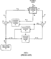
- an acoustic system 10 is subject to external noise sources 11.
- An acoustic actuator 12, preferably a loud speaker driven by an actuator drive signal 14, is used to generate a controlled sound that interferes destructively with an unwanted noise.
- the controlled sound may be an anti-noise signal having the same amplitude, yet 180 degrees out of phase with the unwanted noise signal.
- the residual noise is measured by a sensor 16, (usually a microphone), to produce a sensed signal 18.
- An error signal 20, derived from the sensed signal 18, is used to adjust the characteristics of the acoustic control system 22.
- this system response model is obtained by using a test signal generator 24 to generate a test signal 26 that is combined at signal combiner 28 with a control system output signal 30 to form the actuator drive signal 14.
- the test signal 26 is also supplied to an acoustic system model 32 to produce an estimated response signal 34.
- the estimated response signal 34 is subtracted from the residual signal or sensed signal 18 at combiner 36 to form the error signal 20.
- the acoustic control system 22 is responsive to the error signal 20 and, optionally, to one or more reference signals 38 from reference sensors 40.
- the effect of the control system output signal 30, which is represented in the actuator drive signal 14 is to drive the acoustic actuator 12 so as to modify the noise in acoustic system 10.
- the error signal 20 is correlated with the test signal 26 in adaptation module 42 and is used to adjust or adapt the parameters of the acoustic system model 32.
- the correlation algorithm serves to reduce the effects of noise from sources other than the test signal 26.
- the correlation algorithm performed by adaptation module 42 as applied to the present invention is described in greater detail below.
- the response to the test signal should be inaudible, since the goal of an active sound control system is usually to reduce an unwanted noise.
- the current invention utilizes the concept of "acoustic masking", which will now be described.
- acoustic masking The ability of one sound to reduce the audibility of another sound is called acoustic masking.
- the amount of masking is the amount by which the threshold of audibility must be increased in the presence of the masking noise. This concept is described in "Fundamentals of Acoustics", L.E. Kinsler et al., third edition, Wiley, 1982. Generally, the amount of masking of a signal by a tone decreases according to the difference in frequencies.
- K has been assigned values in the range of 3-6 dB.
- the psycho-acoustic model utilized with the present invention is implemented by masking spectrum generator 62 and is described in greater detail below.
- a variety of empirical models may be used without departing from the scope of the present invention.
- the present invention uses the unwanted noise from external sources 11 to mask the test signal (such as test signal 26) and thereby make it substantially inaudible. For example, if the external noise has a strong tonal component at one frequency, the level of the test signal at nearby frequencies can be set relative to this level. Even if the response to the test signal at these nearby frequencies is much higher than the external noise level at these frequencies, the test signal will still be inaudible because of the acoustic masking property. This is a considerable improvement over prior schemes in which the test signal level was chosen with regard only to external noise at the same frequency. In the present invention, the test signal at the nearby frequencies is louder, enabling the system response model to be estimated more accurately and significantly faster.
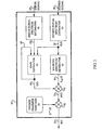
- a block diagram of the present invention is shown in Figure 2.
- the basic operation of the common functional blocks is similar to the system described in Figure 1, except that the test signal 26 is replaced a spectrally shaped test signal 46.
- the shaped signal generator 44 produces the spectrally shaped test signal 46.
- This spectral shaping of test signal 46 is continually updated to ensure that the sound due to the spectrally shaped test signal is masked by the external noise 11.
- the sensed signal 18, from the sensor or microphone 16 is passed to a masking threshold generator 50.
- the masking threshold generator 50 is used to estimate spectral shaping parameters 52 utilized by the shaped signal generator 44 for generating the spectrally shaped test signal 46.
- the masking threshold generator 50 utilizes a perceptual model of hearing. In one embodiment the masking threshold generator 50 is also responsive to an estimated response signal 34 generated by the acoustic system model 32.
- the spectrally shaped test signal 46 is combined by signal combiner 28 with the control signal 30 produced by the acoustic control system 22 to form the actuator drive signal 14.
- the shaped test signal 46 is also supplied to an acoustic system model 32 to produce the estimated response signal 34.
- the estimated response signal 34 is subtracted from the sensed signal 18 at signal combiner 36 to form the error signal 20.
- the acoustic control system 22 is responsive to the error signal 20 and, optionally, signals 38 from reference sensors 40.
- the effect of the actuator drive signal 14 is to drive the acoustic actuator 12 so as to modify the noise in the acoustic system 10.
- the error signal 20 is correlated with the spectrally shaped test signal 46 in adaptation module 42 and is used by the adaptation module 42 to adjust or adapt the parameters of the acoustic system model 32.
- the correlation function serves to reduce the effects of noise from sources other than the spectrally shaped test signal 46.
- LMS Least Mean Square
- Widrow B. Widrow and S.D. Stearns, "Adaptive Signal Processing", Chapter 6, Prentice Hall, 1985
- J.J. Shynk Frequency Domain and Multirate Adaptive Filtering
- the frequency spectrum 56 of sensed signal 18 is estimated by the sensed signal spectrum estimator 54. This may be a broadband frequency spectrum or a harmonic frequency spectrum.
- the frequency spectrum 56 is used by masking spectrum generator 62 to calculate an initial spectral masking threshold 64.
- the initial spectral masking threshold 64 is optionally multiplied by spectral gains 68 (produced by gain estimator 66) at multiplier 70 to produce a modified or scaled spectral masking threshold 72.
- This scaled spectral masking threshold 72 is further scaled by an inverse transfer function 74 at multiplier 76 to produce the spectral shaping parameters 52 as an output of the masking threshold generator 50.
- the inverse transfer function 74 is set a set of stored values (for each frequency) and represents the gain or attenuation that must be applied to the spectrally shaped test signal 46 to compensate for the response of the acoustic system 10.
- the values are not required to a high accuracy, unlike the transfer function used by the controller of the acoustic control system 22.
- the initial spectral masking threshold 64 represents the spectrum of a test signal that would produce the desired response at the sensor 16, that is a response that will be acoustically masked by the ambient sound. However, the accuracy of this initial spectral masking threshold 64 depends on estimates of the inverse transfer function 74 and the ambient noise level; neither of which is known with certainty.
- the frequency spectrum 56 of sensed signal 18 contains energy produced by the spectrally shaped test signal 46 and by the external noise sources 11. It may therefore be necessary to modify the initial spectral masking threshold 64 at some frequencies to account for this. In the embodiment shown in Figure 3, this modification is achieved by scaling the initial spectral masking threshold 64 by spectral gains 68 generated by gain estimator 66.
- the purpose of the spectral gain 68 is to compensate for errors in the estimate of the inverse transfer function 74 or the ambient noise level. It has been described above how the transfer function accuracy depends upon the ratio of the test signal level (as measured at the sensor) to the ambient noise level. Hence, if the transfer function accuracy is poor it is likely because (a) the test signal level is too low or (b) the acoustic system response has changed. In either case it desirable to increase the level of the test signal in order to improve accuracy. This improvement in accuracy is achieved by multiplying the spectrum by a gain factor, such as spectral gains 68 which are generated by the gain estimator 66. The gain factor is increased if the transfer function accuracy is thought to be too low, and decreased if it is higher than necessary (so as to minimize the level of the test signal).
- the spectral gains 68 are calculated by gain estimator 66 according to the power spectrum 60 of the error signal 20, which is calculated by the error signal spectrum estimator 58, and according to the frequency spectrum 56 from sensed signal spectrum estimator 54. This may be a recursive calculation, which also depends on previous gains 68 from gain estimator 66.
- Figure 4 shows a time-domain, shaped test signal generator 44.
- the spectral shaping parameters 52 are supplied to inverse transform block 80 to produce the coefficients 82 for a time-domain shaping filter 84.
- a test signal generator 86 produces a pseudo-random signal 88 with substantially equal energy in each frequency band. This signal is passed through the shaping filter 84 to produce the spectrally shaped test signal 46.
- Figure 5 shows a frequency domain, shaped test signal generator 44'.
- a test spectrum generator 90 generates a complex frequency spectrum 92 with uniform amplitude and random phase. This complex frequency spectrum 92 is multiplied by spectral shaping parameters 52 at multiplier 94 to produce the spectrum of the shaped test signal 96. An inverse transform is applied at block 98 to produce the spectrally shaped test signal 46. Further detailed description of the various elements associated with the system of the present invention is provided below.
- the function provided by the masking threshold generator 50 of the present invention can be modeled as follows.
- the sensed signal 18 in Figure 3, at time sample n is denoted by r ( n ).
- the Fourier transform of r(n) is calculated by the sensed signal spectrum estimator 54.
- the transform may be calculated as: where N is the transform block size and T is the sampling period.
- the Fourier transform at frequency f is denoted by R ( f ).exp( i ⁇ ( f )), where R ( f ) is the amplitude of the spectrum and ⁇ ( f ) is the phase of frequency spectrum 56.
- the initial spectral masking threshold 64 at frequency f is given by where The parameters K , ⁇ and ⁇ may be adjusted to control the amount of masking modeled.
- the initial spectral masking threshold 64 is calculated by the masking spectrum generator 62 using this psycho-acoustical model above.
- the spectral gain adjustment performed by the masking threshold generator 50 is described as follows.
- a large value of the amplitude of ⁇ ( f ) indicates that H ( f ) (the transfer function) is large compared to h(f) (the error in the transfer function).
- the spectral gain 68 is adjusted by the gain estimator block 66 so that the amplitude of the ratio ⁇ ( f ) is maintained above some minimum level for frequencies between the discrete frequencies.
- the masking threshold generator 50 Compensation for the system transfer function is accomplished by the masking threshold generator 50 as follows.
- the sound due to the spectrally shaped test signal 46 will be modified by the transfer function of the acoustic system 10 (including the actuator response function, the sensor response function and acoustic propagation).
- the initial spectral masking threshold 64 must be modified accordingly to compensate for this transfer function.
- the detailed transfer function is not known, since this is what the invention seeks to identify, but the general form of the transfer function is usually known from previous measurements, or from knowledge of the acoustic system 10.
- the phase of the transfer function is generally more important than the amplitude, since the adaptation rate may always be reduced to compensate for amplitude errors.
- the prior estimate or measurement of the transfer function, at frequency f is denoted as H(f).
- a minimum level may be set for S ( f ) in order to prevent underflow errors or errors due to non-linearities in the acoustic system. This minimum level may be set relative to the largest value of S ( f ).
- the external disturbance of the system is characterized by a frequency spectrum that contains sound power in discrete, narrow frequency bands.
- An example of a noise spectrum resulting from such a disturbance is shown in Figure 6.
- Figure 6 shows the amplitude of the external noise 11 in decibels (dB) as a function of frequency measured in Hertz.
- the fundamental frequency of the external noise 11 is 40 Hz.
- the spectral masking threshold or spectral shaping parameters 52 shown as the heavier line in Figure 6, has sound power across a broad frequency range.
- the spectral masking threshold 52 is about 20dB below the frequency spectrum of the external noise. Between the discrete frequencies, the spectral masking threshold 52 is considerably higher than the frequency spectrum of the external noise 11. However, a spectrally shaped test signal 46 shaped by the spectral masking threshold 52 will still be substantially inaudible.
- the prior art system response identification systems use a test signal 26 that is set at each frequency according to the noise at that same frequency. The resulting signal is produced at a much lower amplitude level than that used in the present invention.
- the spectrally shaped test signal 46 used in the present invention is louder, it is masked by the nearby discrete tone and is therefore substantially inaudible. Accordingly, at frequencies between the discrete frequencies, the shaped test signal 46 of the present invention is loud compared to the external noise 11, enabling a very rapid identification of the acoustic system model 32.
- the acoustic system model 32 is identified using an adaptive algorithm implemented within the adaptation module 42 in which the change to the model at each iteration of the algorithm is proportional to the misadjustment and to a convergence step size.
- the time taken to identify the acoustic system model 32 is related to the step size as shown in Figure 7.
- Figure 7 shows the number of iterations (i.e. the time) for a model to converge to within 10% of its final estimate as a function of the convergence step size.
- the current invention provides a technique by which much higher signal-to-noise ratios may be used (between the discrete frequencies), and therefore increases the accuracy of the resulting acoustic system model 32 and/or reduces the time required to estimate the acoustic system model 32.
- the transfer function of the acoustic system model 32 may be estimated via interpolation from nearby frequencies.
- the frequencies to be interpolated are determined by measuring the frequencies of the noise or the repetition rate of the machine (using a tachometer for example).
- a joint estimation of the external noise d(n) 11 and the acoustic system model 32 can be made as described in co-pending U.S. Patent Application Serial No. 09/108,253, filed on July 1, 1998.
- the adaptation of the acoustic system model 32 is preferably performed in the frequency domain, so that the noise at the discrete frequencies does not degrade the adaptation process.
Abstract
Description
- This invention relates to the active control of noise in an acoustic system and, in particular, to the identification of a mathematical model of the acoustic system.
- A review of active control systems for the active control of sound is provided in the text "Active Control of Sound", by P.A. Nelson and S.J. Elliott, Academic Press, London. Most of the control systems used for active control are adaptive systems wherein the controller characteristic or output is adjusted in response to measurements of the residual disturbance or noise. If these adjustments are to improve the performance of the system, then it is necessary to know how the system will respond to any changes. This invention relates to methods for obtaining this knowledge through measurements.
- Usually the active noise control system is characterized by the system impulse response, which is the time response, at a particular controller input, due to impulse at a particular controller output. This response depends upon the input and output processes of the system, such as actuator response, sensor response, smoothing and anti-aliasing filter responses, among other responses. For multichannel systems, a matrix of impulse responses is required, one for each input/output pair. For a sampled data representation, the impulse between the j th output and the i th input at the n th sample will be denoted by a ij(n).
- Equivalently, the system can be characterized by a matrix of transfer functions, which correspond to the Fourier transforms of the impulse responses. These are defined for the k th frequency bywhere N is an integer, the k th frequency is (k/NT) and T is the sampling period in seconds.

- The objective of system response identification is to find a mathematical model for the acoustic response of the system. The most common technique for system response identification is to send a random test signal from the controller output, and measure a response signal at the controller input. The response signal is correlated with the random test signal so as to reduce the effects of noise from other sources.
- For many stochastic signals, the correlation can be estimated as a time average of products of the signals. For uncorrelated signals, the time-averaged power of the noise component will decrease in proportion to the averaging time. For example, if a test signal s(n) is used at time sample n to excite a system, the measured response y(n) will have two components. A first component r(n), which is the response to the test signal, and a second component d(n) which is due to ambient noise. The correlation, at a lag of m samples, between the measured response y(n) and the test signal s(n) is estimated by the time average over N samples, namelywhere y(n) = r(n) + d(n).

- The expected value of this correlation can be written asThe first term on the right hand side,
 is the expected value of the time-averaged product of the test signal with the response to the test signal. The second term on the right hand side,
 is the expected value of the time-averaged product of the test signal with the noise.
- The system impulse response coefficient a(m) at lag m can be estimated as
- To obtain an accurate estimate of the system response model in a short amount of time, it is therefore necessary to use a high-level or high amplitude test signal. However, this technique is in conflict to the requirement that the sound produced by the test signal must be quiet enough that it is not objectionable, since the primary purpose of an active control system is usually to reduce noise.
- Prior schemes, such as those disclosed by the current inventor in U.S. Patent No. 5,553,153, which is incorporated by reference herein, have sought to fix the accuracy of the system response model by adjusting the spectrum of the test signal so that the ratio of the test signal response to external noise is the same at each frequency. However, the prior art does not address the problem of how to maximize the accuracy or minimize the estimation time. The problem of subjective assessment of the system is also not addressed in the prior art. Moreover, in an ideal system the sound produced by the test signal should be inaudible. In the prior systems, the test signal is clearly audible, which is unacceptable in many applications.
- Therefore, a need currently exists for a technique for system response identification that maximizes the accuracy of the estimated system response model and minimizes the time taken to obtain or update the estimate. There is also a need for a technique for system response identification that uses a substantially inaudible test signal. This technique for system response identification may utilize a variety of models, including transfer function models and impulse response models.
- The present invention is a system and method for identifying a mathematical model of an acoustic system in the presence of noise. The system comprises a sensor, which produces a sensed signal in response to the noise at one location within the acoustic system, an acoustic actuator for producing controlled sounds within the acoustic system, and a signal processing module. The frequency spectral content of the noise is measured from the sensed signal, and a psycho-acoustical model is used to calculate a spectral masking threshold, below which added noise is substantially inaudible. The spectral masking threshold, together with a prior estimate of the transfer function between the input to the acoustic actuator and the sensed signal, is used to calculate a desired test signal spectrum. A signal generator is used to generate a spectrally shaped, random test signal with the desired spectrum. This test signal is supplied to the acoustic actuator, thereby producing a controlled sound within the acoustic system. The spectrally shaped test signal is also used as an input to an acoustic system model of the acoustic system, which includes the acoustic actuator and sensor and any associated signal conditioning devices.
- The parameters of the acoustic system model are adjusted using a correlation algorithm according to the difference between the output from the acoustic system model and the sensed signal, which is responsive to the combination of the noise and the controlled sound. The correlation algorithm is implemented by an adaptation module. The frequency spectrum of the response to the spectrally shaped test signal is at or below the masking threshold and is therefore substantially inaudible.
- One object of the present invention is to provide a system and method for the identification of a mathematical model of an acoustic system using a substantially inaudible test signal.
- Another object is to provide a system and method for the identification of a mathematical model of an acoustic system, which provides improved accuracy.
- A further object of the present invention is to provide a system and method for the identification of a mathematical model of an acoustic system, which provides improved convergence speed.
- Additional objects, advantages and features of the present invention will become apparent from the following description and appended claims, taken in conjunction with the accompanying drawings in which:
- Figure 1 is a block diagram of an active control system of the prior art, which incorporates on-line system identification;
- Figure 2 is a block diagram of an active control system which incorporates improved on-line system identification in accordance with a preferred embodiment of the present invention;
- Figure 3 is a block diagram of a masking threshold generator according to the teachings of the present invention;
- Figure 4 is a block diagram of a time-domain, shaped test signal generator in accordance with the present invention;
- Figure 5 is a block diagram of a frequency-domain, shaped test signal generator in accordance with the present invention;
- Figure 6 is a graph depicting an example noise spectrum and a corresponding masking spectrum derived according to one embodiment of the invention; and
- Figure 7 is a graph depicting the relationship between convergence time and signal-to-noise ratio for a system response identification system.
-
- In an active sound control system, such as that shown in Figure 1, an
acoustic system 10 is subject to external noise sources 11. Anacoustic actuator 12, preferably a loud speaker driven by anactuator drive signal 14, is used to generate a controlled sound that interferes destructively with an unwanted noise. For example, the controlled sound may be an anti-noise signal having the same amplitude, yet 180 degrees out of phase with the unwanted noise signal. In an adaptive system, the residual noise is measured by a sensor 16, (usually a microphone), to produce a sensedsignal 18. Anerror signal 20, derived from the sensedsignal 18, is used to adjust the characteristics of theacoustic control system 22. - Two examples of control systems that can be used with the present invention include U.S. Patent No. 5,091,953 to Tretter which describes a multiple channel control system for periodic noise based on the discrete Fourier transform (DFT), and U.S. Patent No. 5,469,087 to Eatwell which describes a control system using harmonic filters. Both of these control systems estimate the amplitude and phase of the residual noise at each of the harmonic frequencies of the noise source. The amplitudes of the residual noise may be used in the present invention as is described in more detail below.
- In order to make the requisite noise adjustment it is usually necessary to determine how the controlled
acoustic system 10 will respond to the new controller output. It is therefore necessary to form a mathematical model of the acoustic system, known as a system response model, so that the response to a given controller output produced by theacoustic control system 22 can be determined. - In the system shown in Figure 1, this system response model is obtained by using a
test signal generator 24 to generate atest signal 26 that is combined atsignal combiner 28 with a controlsystem output signal 30 to form theactuator drive signal 14. Thetest signal 26 is also supplied to anacoustic system model 32 to produce an estimatedresponse signal 34. The estimatedresponse signal 34 is subtracted from the residual signal or sensedsignal 18 atcombiner 36 to form theerror signal 20. Theacoustic control system 22 is responsive to theerror signal 20 and, optionally, to one or more reference signals 38 fromreference sensors 40. The effect of the controlsystem output signal 30, which is represented in theactuator drive signal 14 is to drive theacoustic actuator 12 so as to modify the noise inacoustic system 10. - The
error signal 20 is correlated with thetest signal 26 inadaptation module 42 and is used to adjust or adapt the parameters of theacoustic system model 32. The correlation algorithm serves to reduce the effects of noise from sources other than thetest signal 26. The correlation algorithm performed byadaptation module 42 as applied to the present invention is described in greater detail below. - Ideally, the response to the test signal should be inaudible, since the goal of an active sound control system is usually to reduce an unwanted noise. In order to produce a test signal that results in a substantially inaudible response, the current invention utilizes the concept of "acoustic masking", which will now be described.
- It is well known that it is more difficult to hear speech in the presence of noise, even if the noise is at different frequencies (for example a loud, low-frequency rumble or a high pitched screech). The ability of one sound to reduce the audibility of another sound is called acoustic masking. The amount of masking is the amount by which the threshold of audibility must be increased in the presence of the masking noise. This concept is described in "Fundamentals of Acoustics", L.E. Kinsler et al., third edition, Wiley, 1982. Generally, the amount of masking of a signal by a tone decreases according to the difference in frequencies.
- In perceptual coding of audio signals, the signal is divided into a number of critical frequency bands (see Cox et al. "On the Application of Multimedia Processing to Communications", Proceedings of the IEEE, Vol. 86, No. 5, May 1998, pp. 773-774). Here, empirical rules for calculating a masking threshold are given.
- In a critical frequency band B, a tone with energy ET will mask noise with energy
- These models are termed 'perceptual models' or 'psycho-acoustic models'. The psycho-acoustic model utilized with the present invention is implemented by masking
spectrum generator 62 and is described in greater detail below. A variety of empirical models may be used without departing from the scope of the present invention. The present invention uses the unwanted noise fromexternal sources 11 to mask the test signal (such as test signal 26) and thereby make it substantially inaudible. For example, if the external noise has a strong tonal component at one frequency, the level of the test signal at nearby frequencies can be set relative to this level. Even if the response to the test signal at these nearby frequencies is much higher than the external noise level at these frequencies, the test signal will still be inaudible because of the acoustic masking property. This is a considerable improvement over prior schemes in which the test signal level was chosen with regard only to external noise at the same frequency. In the present invention, the test signal at the nearby frequencies is louder, enabling the system response model to be estimated more accurately and significantly faster. - A block diagram of the present invention is shown in Figure 2. The basic operation of the common functional blocks is similar to the system described in Figure 1, except that the
test signal 26 is replaced a spectrally shapedtest signal 46. The shaped signal generator 44 produces the spectrally shapedtest signal 46. This spectral shaping oftest signal 46 is continually updated to ensure that the sound due to the spectrally shaped test signal is masked by theexternal noise 11. The sensedsignal 18, from the sensor or microphone 16, is passed to amasking threshold generator 50. Themasking threshold generator 50 is used to estimatespectral shaping parameters 52 utilized by the shaped signal generator 44 for generating the spectrally shapedtest signal 46. Themasking threshold generator 50 utilizes a perceptual model of hearing. In one embodiment themasking threshold generator 50 is also responsive to an estimatedresponse signal 34 generated by theacoustic system model 32. - The spectrally shaped
test signal 46 is combined bysignal combiner 28 with thecontrol signal 30 produced by theacoustic control system 22 to form theactuator drive signal 14. The shapedtest signal 46 is also supplied to anacoustic system model 32 to produce the estimatedresponse signal 34. The estimatedresponse signal 34 is subtracted from the sensedsignal 18 atsignal combiner 36 to form theerror signal 20. Theacoustic control system 22 is responsive to theerror signal 20 and, optionally, signals 38 fromreference sensors 40. The effect of theactuator drive signal 14 is to drive theacoustic actuator 12 so as to modify the noise in theacoustic system 10. - The
error signal 20 is correlated with the spectrally shapedtest signal 46 inadaptation module 42 and is used by theadaptation module 42 to adjust or adapt the parameters of theacoustic system model 32. The correlation function serves to reduce the effects of noise from sources other than the spectrally shapedtest signal 46. Many time or frequency domain adaptation schemes (for implementation by adaptation module 42) are known in the prior art, including the Least Mean Square (LMS) algorithm of Widrow (B. Widrow and S.D. Stearns, "Adaptive Signal Processing", Chapter 6, Prentice Hall, 1985), and the frequency domain algorithms described by J.J. Shynk ("Frequency Domain and Multirate Adaptive Filtering", IEEE Signal Processing Magazine, January 1992, pages 14-37). - For example, in the time-domain LMS algorithm scheme, each impulse response coefficient a(m) is updated according to

- In a simple frequency domain update scheme, the transfer function A(f) at frequency f is updated according to
- The operation of the
masking threshold generator 50 of the present invention will now be described with reference to the embodiment shown in Figure 3. Thefrequency spectrum 56 of sensedsignal 18 is estimated by the sensedsignal spectrum estimator 54. This may be a broadband frequency spectrum or a harmonic frequency spectrum. Thefrequency spectrum 56 is used by maskingspectrum generator 62 to calculate an initialspectral masking threshold 64. The initialspectral masking threshold 64 is optionally multiplied by spectral gains 68 (produced by gain estimator 66) at multiplier 70 to produce a modified or scaledspectral masking threshold 72. This scaledspectral masking threshold 72 is further scaled by aninverse transfer function 74 atmultiplier 76 to produce thespectral shaping parameters 52 as an output of themasking threshold generator 50. - The
inverse transfer function 74 is set a set of stored values (for each frequency) and represents the gain or attenuation that must be applied to the spectrally shapedtest signal 46 to compensate for the response of theacoustic system 10. The values are not required to a high accuracy, unlike the transfer function used by the controller of theacoustic control system 22. - The initial
spectral masking threshold 64 represents the spectrum of a test signal that would produce the desired response at the sensor 16, that is a response that will be acoustically masked by the ambient sound. However, the accuracy of this initialspectral masking threshold 64 depends on estimates of theinverse transfer function 74 and the ambient noise level; neither of which is known with certainty. - The
frequency spectrum 56 of sensedsignal 18 contains energy produced by the spectrally shapedtest signal 46 and by the external noise sources 11. It may therefore be necessary to modify the initialspectral masking threshold 64 at some frequencies to account for this. In the embodiment shown in Figure 3, this modification is achieved by scaling the initialspectral masking threshold 64 byspectral gains 68 generated bygain estimator 66. - The purpose of the
spectral gain 68 is to compensate for errors in the estimate of theinverse transfer function 74 or the ambient noise level. It has been described above how the transfer function accuracy depends upon the ratio of the test signal level (as measured at the sensor) to the ambient noise level. Hence, if the transfer function accuracy is poor it is likely because (a) the test signal level is too low or (b) the acoustic system response has changed. In either case it desirable to increase the level of the test signal in order to improve accuracy. This improvement in accuracy is achieved by multiplying the spectrum by a gain factor, such asspectral gains 68 which are generated by thegain estimator 66. The gain factor is increased if the transfer function accuracy is thought to be too low, and decreased if it is higher than necessary (so as to minimize the level of the test signal). - The
spectral gains 68 are calculated bygain estimator 66 according to thepower spectrum 60 of theerror signal 20, which is calculated by the errorsignal spectrum estimator 58, and according to thefrequency spectrum 56 from sensedsignal spectrum estimator 54. This may be a recursive calculation, which also depends onprevious gains 68 fromgain estimator 66. - Two embodiments of the shaped test signal generator 44 will now be described with reference to Figures 4 and 5. Figure 4 shows a time-domain, shaped test signal generator 44. The
spectral shaping parameters 52 are supplied toinverse transform block 80 to produce thecoefficients 82 for a time-domain shaping filter 84. Atest signal generator 86 produces apseudo-random signal 88 with substantially equal energy in each frequency band. This signal is passed through the shapingfilter 84 to produce the spectrally shapedtest signal 46. - Figure 5 shows a frequency domain, shaped test signal generator 44'. A
test spectrum generator 90 generates acomplex frequency spectrum 92 with uniform amplitude and random phase. Thiscomplex frequency spectrum 92 is multiplied byspectral shaping parameters 52 atmultiplier 94 to produce the spectrum of the shapedtest signal 96. An inverse transform is applied atblock 98 to produce the spectrally shapedtest signal 46. Further detailed description of the various elements associated with the system of the present invention is provided below. - The function provided by the
masking threshold generator 50 of the present invention can be modeled as follows. The sensedsignal 18 in Figure 3, at time sample n is denoted by r(n). The Fourier transform of r(n) is calculated by the sensedsignal spectrum estimator 54. The transform may be calculated as:where N is the transform block size and T is the sampling period. The Fourier transform at frequency f is denoted by R(f).exp(i(f)), where R(f) is the amplitude of the spectrum and (f) is the phase of
frequency spectrum 56. - In one embodiment of the invention the initial
spectral masking threshold 64 at frequency f is given bywhere The parameters K, α and β may be adjusted to control the amount of masking modeled. In the preferred embodiment, the initial
spectral masking threshold 64 is calculated by themasking spectrum generator 62 using this psycho-acoustical model above. - The spectral gain adjustment performed by the
masking threshold generator 50 is described as follows. The initial spectral masking threshold Em(f) 64 may optionally be multiplied by spectral gains G(f) 68 (produced by gain estimator 66) at multiplier 70 to produce a scaled or modified spectral masking threshold M(f) = G(f).EM (f) 72. - The
frequency spectrum 56 of the sensedsignal 18 is given byacoustic system 10. - The
spectrum 60 of theerror signal 20 is:signal frequency spectrum 56 to theerror signal spectrum 60, at frequency f, is given by - In general, a large value of the amplitude of Γ(f) indicates that H(f) (the transfer function) is large compared to h(f) (the error in the transfer function). In one embodiment of the present invention the
spectral gain 68 is adjusted by thegain estimator block 66 so that the amplitude of the ratio Γ(f) is maintained above some minimum level for frequencies between the discrete frequencies. - Compensation for the system transfer function is accomplished by the
masking threshold generator 50 as follows. The sound due to the spectrally shapedtest signal 46 will be modified by the transfer function of the acoustic system 10 (including the actuator response function, the sensor response function and acoustic propagation). The initialspectral masking threshold 64 must be modified accordingly to compensate for this transfer function. The detailed transfer function is not known, since this is what the invention seeks to identify, but the general form of the transfer function is usually known from previous measurements, or from knowledge of theacoustic system 10. For active noise control, the phase of the transfer function is generally more important than the amplitude, since the adaptation rate may always be reduced to compensate for amplitude errors. - The prior estimate or measurement of the transfer function, at frequency f, is denoted as H(f). The inverse H -1 (f) of the transfer is stored at
block 74 and is multiplied by the scaled or modifiedspectral masking threshold 72 bymultiplier 76 to give the spectral shaping parameters 52 - Finally, a minimum level may be set for S(f) in order to prevent underflow errors or errors due to non-linearities in the acoustic system. This minimum level may be set relative to the largest value of S(f).
- One important application of the present invention is for identifying the response of dynamic systems subject to periodic or tonal disturbances. The external disturbance of the system is characterized by a frequency spectrum that contains sound power in discrete, narrow frequency bands. An example of a noise spectrum resulting from such a disturbance is shown in Figure 6. Figure 6 shows the amplitude of the
external noise 11 in decibels (dB) as a function of frequency measured in Hertz. In this example, the fundamental frequency of theexternal noise 11 is 40 Hz. The spectral masking threshold orspectral shaping parameters 52, shown as the heavier line in Figure 6, has sound power across a broad frequency range. In this example of the invention thespectral masking threshold 52 at frequency f is given bywhere and K = 0.1, α = 0.75 and β = 3.
- At the discrete frequencies of the
external noise 11 thespectral masking threshold 52 is about 20dB below the frequency spectrum of the external noise. Between the discrete frequencies, thespectral masking threshold 52 is considerably higher than the frequency spectrum of theexternal noise 11. However, a spectrally shapedtest signal 46 shaped by thespectral masking threshold 52 will still be substantially inaudible. The prior art system response identification systems use atest signal 26 that is set at each frequency according to the noise at that same frequency. The resulting signal is produced at a much lower amplitude level than that used in the present invention. Although the spectrally shapedtest signal 46 used in the present invention is louder, it is masked by the nearby discrete tone and is therefore substantially inaudible. Accordingly, at frequencies between the discrete frequencies, the shapedtest signal 46 of the present invention is loud compared to theexternal noise 11, enabling a very rapid identification of theacoustic system model 32. - There is a direct relationship between the signal-to-noise ratio (i.e. the ratio of the test signal amplitude to the external noise amplitude) and the convergence time or accuracy of the
acoustic system model 32. Theacoustic system model 32 is identified using an adaptive algorithm implemented within theadaptation module 42 in which the change to the model at each iteration of the algorithm is proportional to the misadjustment and to a convergence step size. The time taken to identify theacoustic system model 32 is related to the step size as shown in Figure 7. Figure 7 shows the number of iterations (i.e. the time) for a model to converge to within 10% of its final estimate as a function of the convergence step size. The number of iterations is reduced as the convergence step size is increased until, finally, only a single iteration is required. Unfortunately, the error in the final estimate of the system response increases with the convergence step size. This error also depends upon the signal to noise ratio. Figure 7 also shows the relationship between the convergence step size and the phase error in the estimated transfer function of theacoustic system model 32 for several different signal-to-noise ratios. The performance of the resulting control system is strongly dependent upon this phase error. - In order to achieve a desired accuracy it is necessary to increase the signal-to-noise ratio or decrease the convergence rate. The current invention provides a technique by which much higher signal-to-noise ratios may be used (between the discrete frequencies), and therefore increases the accuracy of the resulting
acoustic system model 32 and/or reduces the time required to estimate theacoustic system model 32. - At the discrete frequencies, the transfer function of the
acoustic system model 32 may be estimated via interpolation from nearby frequencies. In the preferred embodiment, the frequencies to be interpolated are determined by measuring the frequencies of the noise or the repetition rate of the machine (using a tachometer for example). Alternatively, a joint estimation of the external noise d(n) 11 and theacoustic system model 32 can be made as described in co-pending U.S. Patent Application Serial No. 09/108,253, filed on July 1, 1998. When the external disturbance is periodic, as in this example, the adaptation of theacoustic system model 32 is preferably performed in the frequency domain, so that the noise at the discrete frequencies does not degrade the adaptation process. - The discussion presented herein discloses and describes exemplary embodiments of the present invention. One skilled in the art will readily recognize from such discussion, and from the accompanying drawings and claims, that various changes, modifications, and variations can be made therein without departing from the spirit and scope of the invention as defined in the following claims.
Claims (32)
- A system for identifying a model of an acoustic system in the presence of an external noise signal, comprising:an acoustic actuator for generating controlled sound within the acoustic system;a sensor for receiving the controlled sound and the external noise signal and producing a sensed signal;a control system for generating a control signal, the control system including a system model for generating an estimated response signal, the control system generating an error signal representing the difference between the sensed signal and the estimated response signal;a masking threshold generator for receiving the sensed signal and the error signal and producing spectral shaping parameters;a shaped signal generator for receiving the spectral shaping parameters and producing a test signal; anda signal combining device for receiving the test signal and the control signal and producing an actuator drive signal for driving the acoustic actuator.
- The system of claim 1 wherein the control system further includes an adaptation module for controlling the system model.
- The system of claim 2 wherein the adaptation module performs a correlation algorithm on the spectrally shaped test signal and provides the result to the system model.
- A masking threshold generator for producing spectral shaping parameters used by a test signal generator for identifying an acoustic system response of an acoustic system, said masking threshold generator comprising:a first spectrum estimator for receiving an error signal from a control system associated with the acoustic system and producing an error signal spectrum;a second spectrum estimator for receiving a feedback signal from the acoustic system, the second spectrum estimator calculating a Fourier transform of the feedback signal and generating a feedback signal frequency spectrum;a masking spectrum generator for receiving the feedback signal frequency spectrum and producing an initial spectral masking threshold;a gain estimator for receiving the feedback signal frequency spectrum and the error signal spectrum and producing a spectral gain signal; anda spectral gain adjustment multiplier for receiving the initial spectral masking threshold and the spectral gain signal and producing a scaled spectral masking threshold representing the spectral shaping parameters of the acoustic system;whereby the test signal generator receives the spectral shaping parameters for generating a test signal for controlling the acoustic system.
- The masking threshold generator of claim 4 further including an inverse transfer function block for storing inverse transfer function parameters relating to the transfer function of the acoustic system.
- The masking threshold generator of claim 5 further including a second multiplier for receiving the scaled spectral masking threshold and the inverse transfer function parameters from the inverse transfer function block and producing said spectral shaping parameters.
- The masking threshold generator of claim 4 wherein the masking spectrum generator implements a psycho-acoustical model for modifying the feedback signal frequency spectrum.
- The masking threshold generator of claim 4 wherein the test signal is substantially inaudible.
- The masking threshold generator of claim 4 wherein the gain estimator implements a spectral gain calculation function based upon a transfer function of the acoustic system.
- A system for identifying a model of an acoustic system in the presence of external noise, comprising:an acoustic actuator for generating controlled sound within the acoustic system, said acoustic actuator being responsive to an actuator drive signal which includes a spectrally shaped test signal;a sensor responsive to a combination of the controlled sound and the external noise at a location within the acoustic system, said sensor producing a sensed signal;a masking threshold generator for determining a spectral masking threshold, said masking threshold generator being responsive to said sensed signal;a test signal generator responsive to said spectral masking threshold for generating said spectrally shaped test signal;an acoustic system model responsive to said spectrally shaped test signal and producing an estimated response signal;signal subtraction means for producing an error signal which is the difference between said sensed signal and said estimated response signal; andadaptation means for adjusting the parameters of said acoustic system model to minimize said error signal, said adaptation means being responsive to said spectrally shaped test signal and to said error signal,wherein the sound generated in response to said spectrally shaped test signal is substantially masked by said external noise.
- The system of claim 10 wherein said masking threshold generator is also responsive to at least one of a prior estimate of the transfer function and an inverse transfer function of said acoustic system, and wherein said spectrally shaped test signal is modified to compensate for a transfer function of the acoustic system.
- The system of claim 11 further including:a control system responsive to said error signal and producing a control signal; andsignal combining means for combining said control signal and said spectrally shaped test signal to produce said actuator drive signal,wherein said actuator drive signal modifies the external noise in said acoustic system.
- The system of claim 12 wherein said control signal is adjusted to minimize the mean square error of the error signal.
- The system of claim 13 further including a sensor for producing a reference signal which is time-related to the external noise, and wherein said control system is also responsive to said reference signal.
- A system for identifying a model of an acoustic system in the presence of an external noise, comprising:an acoustic actuator for generating controlled sound within the acoustic system, the acoustic actuator being responsive to an actuator drive signal which includes a spectrally shaped test signal;a sensor for producing a sensed signal, the sensor being responsive to a combination of the controlled sound and the external noise at a location within the acoustic system;a masking threshold generator for determining a spectral masking threshold, the masking threshold generator being responsive to the sensed signal;a shaped test signal generator for generating the spectrally shaped test signal, the shaped test signal generator being responsive to the spectral masking threshold level;an acoustic system model for receiving the spectrally shaped test signal and producing an estimated response signal; anda signal subtraction device for producing an error signal, the error signal being the difference between the sensed signal and the estimated response signal;wherein the controlled sound generated in response to the spectrally shaped test signal is substantially masked by the external noise.
- The system of Claim 15 wherein the test signal generator implements a time domain algorithm for producing the test signal.
- The system of Claim 16 wherein the time domain algorithm includes a shaping filter.
- The system of Claim 15 wherein the test signal generator implements a frequency domain algorithm for producing the test signal.
- The system of claim 17 wherein the frequency domain algorithm includes an inverse transform function.
- The system of claim 15 wherein the acoustic system model includes an adaptation module for providing adjustment parameters to the acoustic system model.
- The system of claim 20 wherein the adaptation module receives the spectrally shaped test signal and the error signal and performs a correlation function for generating the adjustment parameters.
- The system of claim 15 wherein the masking threshold generator calculates a Fourier transform of the sensed signal for producing a sensed signal frequency spectrum.
- The system of claim 22 wherein the masking threshold generator includes a masking spectrum generator for receiving the sensed signal frequency spectrum and producing an initial spectral masking threshold representing signal parameters below which sound produced by the spectrally shaped test signal within the acoustic system will be masked by the external noise.
- The system of claim 23 wherein the masking threshold generator includes an inverse transfer function module for storing inverse transfer function parameters relating to the transfer function of the acoustic system, and wherein the inverse transfer function parameters are applied to the initial spectral masking threshold for producing the spectral masking threshold level provided to the shaped test signal generator.
- The system of claim 23 wherein the masking threshold generator includes a gain estimator for receiving the sensed signal frequency spectrum and producing a spectral gain signal, the gain estimator implementing a spectral gain calculation function based upon a transfer function of the acoustic system.
- The system of claim 25 wherein the spectral gain signal is combined with the initial spectral masking threshold for producing the spectral masking threshold level provided to the shaped test signal generator.
- A method for identifying a model of an acoustic system in the presence of external noise, comprising the steps of:generating a test signal;generating an actuator signal which includes said test signal;supplying said actuator signal to an acoustic actuator for generating a controlled sound within the acoustic system;sensing a combination of the external noise and the controlled sound at one location within the acoustic system to obtain a sensed signal;determining the frequency spectrum of the external noise from said sensed signal;using a psycho-acoustical model to calculate an initial spectral masking threshold from said frequency spectrum, below which added sound is substantially inaudible;modifying said initial spectral masking threshold to compensate for the transfer function between the input to the acoustic actuator and the sensed signal to produce a modified spectral masking threshold;adjusting a frequency spectral content of said test signal to be at or below said modified spectral masking threshold;inputting said test signal to an acoustic system model; andadjusting the parameters of said acoustic system model according to an error signal which is the difference between the output from the acoustic system model and the sensed signal,whereby the controlled sound is substantially inaudible and the characteristics of said acoustic system model approach the characteristics of the acoustic system.
- The method of claim 27 including the steps of:generating a control signal in response to the error signal; andadjusting said control signal to minimize the error signal,wherein said actuator signal is generated by combining said control signal and said test signal.
- The method of claim 28 wherein said control signal is also responsive to a reference signal which is time-related to the external noise.
- The method of claim 27 wherein the parameters of said acoustic system model are system transfer function values and are adjusted according to a frequency domain algorithm.
- The method of claim 30 wherein the external noise is predominately at discrete frequencies and in which the system transfer function values at discrete frequencies of the external noise are obtained by interpolation from values at nearby frequencies.
- The method of claim 30 wherein the frequency spectral content of said test signal is further adjusted so as to maintain the ratio of the frequency spectrum of the sensed signal to the frequency spectrum of the error signal above a specified level for frequencies between the discrete frequencies of the external noise.
Applications Claiming Priority (2)
| Application Number | Priority Date | Filing Date | Title |
|---|---|---|---|
| US09/195,294 US6594365B1 (en) | 1998-11-18 | 1998-11-18 | Acoustic system identification using acoustic masking |
| US195294 | 1998-11-18 |
Publications (3)
| Publication Number | Publication Date |
|---|---|
| EP1003154A2 true EP1003154A2 (en) | 2000-05-24 |
| EP1003154A3 EP1003154A3 (en) | 2002-08-07 |
| EP1003154B1 EP1003154B1 (en) | 2006-05-31 |
Family
ID=22720842
Family Applications (1)
| Application Number | Title | Priority Date | Filing Date |
|---|---|---|---|
| EP99302391A Expired - Lifetime EP1003154B1 (en) | 1998-11-18 | 1999-03-29 | Acoustic system identification using acoustic masking |
Country Status (3)
| Country | Link |
|---|---|
| US (1) | US6594365B1 (en) |
| EP (1) | EP1003154B1 (en) |
| DE (1) | DE69931580T2 (en) |
Cited By (11)
| Publication number | Priority date | Publication date | Assignee | Title |
|---|---|---|---|---|
| EP1162599A2 (en) * | 2000-06-05 | 2001-12-12 | Siemens Canada Limited | Recalibration of active noise cancellation system |
| WO2007077420A2 (en) * | 2005-12-30 | 2007-07-12 | Peter Craven | Enhanced feedback for plant control |
| EP1947642A1 (en) | 2007-01-16 | 2008-07-23 | Harman/Becker Automotive Systems GmbH | Active noise control system |
| WO2010004098A1 (en) * | 2008-07-11 | 2010-01-14 | Commissariat A L'energie Atomique | Estimation of the impulse response of a system on the basis of binary observations |
| US7728658B2 (en) | 2007-07-25 | 2010-06-01 | D2Audio Corporation | Low-noise, low-distortion digital PWM amplifier |
| WO2010074899A2 (en) * | 2008-12-23 | 2010-07-01 | Bose Corporation | Masking based gain control |
| US7812666B2 (en) | 2005-12-30 | 2010-10-12 | D2Audio Corporation | Low delay corrector |
| US8229125B2 (en) | 2009-02-06 | 2012-07-24 | Bose Corporation | Adjusting dynamic range of an audio system |
| US8442251B2 (en) | 2009-04-02 | 2013-05-14 | Oticon A/S | Adaptive feedback cancellation based on inserted and/or intrinsic characteristics and matched retrieval |
| US8964997B2 (en) | 2005-05-18 | 2015-02-24 | Bose Corporation | Adapted audio masking |
| CN107210032A (en) * | 2015-01-20 | 2017-09-26 | 弗劳恩霍夫应用研究促进协会 | The voice reproduction equipment of reproducing speech is sheltered in voice region is sheltered |
Families Citing this family (22)
| Publication number | Priority date | Publication date | Assignee | Title |
|---|---|---|---|---|
| EP1216598B1 (en) | 1999-09-10 | 2005-02-09 | Starkey Laboratories, Inc. | Audio signal processing |
| GB0023207D0 (en) * | 2000-09-21 | 2000-11-01 | Royal College Of Art | Apparatus for acoustically improving an environment |
| US8477958B2 (en) | 2001-02-26 | 2013-07-02 | 777388 Ontario Limited | Networked sound masking system |
| EP1298646B1 (en) * | 2001-10-01 | 2006-01-11 | Koninklijke KPN N.V. | Improved method for determining the quality of a speech signal |
| US7450725B2 (en) * | 2001-12-17 | 2008-11-11 | Mahle International Gmbh | Digital filter modeling for active noise cancellation |
| AU2003210111A1 (en) * | 2002-01-07 | 2003-07-24 | Ronald L. Meyer | Microphone support system |
| CA2422086C (en) * | 2003-03-13 | 2010-05-25 | 777388 Ontario Limited | Networked sound masking system with centralized sound masking generation |
| CA2471674A1 (en) * | 2004-06-21 | 2005-12-21 | Soft Db Inc. | Auto-adjusting sound masking system and method |
| EP1770685A1 (en) * | 2005-10-03 | 2007-04-04 | Maysound ApS | A system for providing a reduction of audiable noise perception for a human user |
| US7933420B2 (en) * | 2006-12-28 | 2011-04-26 | Caterpillar Inc. | Methods and systems for determining the effectiveness of active noise cancellation |
| US8068616B2 (en) * | 2006-12-28 | 2011-11-29 | Caterpillar Inc. | Methods and systems for controlling noise cancellation |
| US8340318B2 (en) * | 2006-12-28 | 2012-12-25 | Caterpillar Inc. | Methods and systems for measuring performance of a noise cancellation system |
| US8767975B2 (en) * | 2007-06-21 | 2014-07-01 | Bose Corporation | Sound discrimination method and apparatus |
| US8243924B2 (en) * | 2007-06-29 | 2012-08-14 | Google Inc. | Progressive download or streaming of digital media securely through a localized container and communication protocol proxy |
| US8620003B2 (en) * | 2008-01-07 | 2013-12-31 | Robert Katz | Embedded audio system in distributed acoustic sources |
| US8611554B2 (en) * | 2008-04-22 | 2013-12-17 | Bose Corporation | Hearing assistance apparatus |
| US8666086B2 (en) * | 2008-06-06 | 2014-03-04 | 777388 Ontario Limited | System and method for monitoring/controlling a sound masking system from an electronic floorplan |
| US8948410B2 (en) * | 2008-12-18 | 2015-02-03 | Koninklijke Philips N.V. | Active audio noise cancelling |
| US20110317522A1 (en) * | 2010-06-28 | 2011-12-29 | Microsoft Corporation | Sound source localization based on reflections and room estimation |
| US9078077B2 (en) | 2010-10-21 | 2015-07-07 | Bose Corporation | Estimation of synthetic audio prototypes with frequency-based input signal decomposition |
| WO2016199119A1 (en) * | 2015-06-06 | 2016-12-15 | Oppenheimer Yehuda | A system and method for active reduction of a predefined audio acoustic noise by using synchronization signals |
| EP3480809B1 (en) * | 2017-11-02 | 2021-10-13 | ams AG | Method for determining a response function of a noise cancellation enabled audio device |
Citations (3)
| Publication number | Priority date | Publication date | Assignee | Title |
|---|---|---|---|---|
| GB2122052A (en) * | 1982-06-09 | 1984-01-04 | Plessey Co Plc | Reducing noise or vibration |
| EP0712115A2 (en) * | 1994-11-08 | 1996-05-15 | Bolt Beranek And Newman Inc. | Active noise and vibration control system accounting for time varying plant, using residual signal to create probe signal |
| US5553153A (en) * | 1993-02-10 | 1996-09-03 | Noise Cancellation Technologies, Inc. | Method and system for on-line system identification |
Family Cites Families (10)
| Publication number | Priority date | Publication date | Assignee | Title |
|---|---|---|---|---|
| US4438526A (en) * | 1982-04-26 | 1984-03-20 | Conwed Corporation | Automatic volume and frequency controlled sound masking system |
| US4677676A (en) | 1986-02-11 | 1987-06-30 | Nelson Industries, Inc. | Active attenuation system with on-line modeling of speaker, error path and feedback pack |
| US4947435A (en) | 1988-03-25 | 1990-08-07 | Active Noise & Vibration Tech | Method of transfer function generation and active noise cancellation in a vibrating system |
| US5091953A (en) * | 1990-02-13 | 1992-02-25 | University Of Maryland At College Park | Repetitive phenomena cancellation arrangement with multiple sensors and actuators |
| DE69327885T2 (en) | 1992-05-26 | 2000-10-05 | Fujitsu Ten Ltd | Noise control device |
| US5524057A (en) | 1992-06-19 | 1996-06-04 | Alpine Electronics Inc. | Noise-canceling apparatus |
| US5469087A (en) * | 1992-06-25 | 1995-11-21 | Noise Cancellation Technologies, Inc. | Control system using harmonic filters |
| KR960009936B1 (en) * | 1992-10-07 | 1996-07-25 | 대우전자 주식회사 | Measuring method and apparatus of audio signal distortion |
| US5475761A (en) | 1994-01-31 | 1995-12-12 | Noise Cancellation Technologies, Inc. | Adaptive feedforward and feedback control system |
| US5625745A (en) * | 1995-01-31 | 1997-04-29 | Lucent Technologies Inc. | Noise imaging protection for multi-channel audio signals |
-
1998
- 1998-11-18 US US09/195,294 patent/US6594365B1/en not_active Expired - Lifetime
-
1999
- 1999-03-29 DE DE69931580T patent/DE69931580T2/en not_active Expired - Fee Related
- 1999-03-29 EP EP99302391A patent/EP1003154B1/en not_active Expired - Lifetime
Patent Citations (3)
| Publication number | Priority date | Publication date | Assignee | Title |
|---|---|---|---|---|
| GB2122052A (en) * | 1982-06-09 | 1984-01-04 | Plessey Co Plc | Reducing noise or vibration |
| US5553153A (en) * | 1993-02-10 | 1996-09-03 | Noise Cancellation Technologies, Inc. | Method and system for on-line system identification |
| EP0712115A2 (en) * | 1994-11-08 | 1996-05-15 | Bolt Beranek And Newman Inc. | Active noise and vibration control system accounting for time varying plant, using residual signal to create probe signal |
Cited By (18)
| Publication number | Priority date | Publication date | Assignee | Title |
|---|---|---|---|---|
| EP1162599A3 (en) * | 2000-06-05 | 2012-06-27 | Siemens VDO Automotive Inc. | Recalibration of active noise cancellation system |
| EP1162599A2 (en) * | 2000-06-05 | 2001-12-12 | Siemens Canada Limited | Recalibration of active noise cancellation system |
| US8964997B2 (en) | 2005-05-18 | 2015-02-24 | Bose Corporation | Adapted audio masking |
| WO2007077420A2 (en) * | 2005-12-30 | 2007-07-12 | Peter Craven | Enhanced feedback for plant control |
| WO2007077420A3 (en) * | 2005-12-30 | 2007-09-07 | Peter Craven | Enhanced feedback for plant control |
| US7756592B2 (en) | 2005-12-30 | 2010-07-13 | Peter Craven | Enhanced feedback for plant control |
| US7812666B2 (en) | 2005-12-30 | 2010-10-12 | D2Audio Corporation | Low delay corrector |
| EP1947642A1 (en) | 2007-01-16 | 2008-07-23 | Harman/Becker Automotive Systems GmbH | Active noise control system |
| CN101354885B (en) * | 2007-01-16 | 2012-10-10 | 哈曼贝克自动系统股份有限公司 | Active noise control system |
| US7728658B2 (en) | 2007-07-25 | 2010-06-01 | D2Audio Corporation | Low-noise, low-distortion digital PWM amplifier |
| WO2010004098A1 (en) * | 2008-07-11 | 2010-01-14 | Commissariat A L'energie Atomique | Estimation of the impulse response of a system on the basis of binary observations |
| US8705597B2 (en) | 2008-07-11 | 2014-04-22 | Commissariat A L'energie Atomique Et Aux Energies Alternatives | Estimation of the impulse response of a system on the basis of binary observations |
| US8218783B2 (en) | 2008-12-23 | 2012-07-10 | Bose Corporation | Masking based gain control |
| WO2010074899A3 (en) * | 2008-12-23 | 2011-04-07 | Bose Corporation | Gain control based masking |
| WO2010074899A2 (en) * | 2008-12-23 | 2010-07-01 | Bose Corporation | Masking based gain control |
| US8229125B2 (en) | 2009-02-06 | 2012-07-24 | Bose Corporation | Adjusting dynamic range of an audio system |
| US8442251B2 (en) | 2009-04-02 | 2013-05-14 | Oticon A/S | Adaptive feedback cancellation based on inserted and/or intrinsic characteristics and matched retrieval |
| CN107210032A (en) * | 2015-01-20 | 2017-09-26 | 弗劳恩霍夫应用研究促进协会 | The voice reproduction equipment of reproducing speech is sheltered in voice region is sheltered |
Also Published As
| Publication number | Publication date |
|---|---|
| US6594365B1 (en) | 2003-07-15 |
| DE69931580D1 (en) | 2006-07-06 |
| DE69931580T2 (en) | 2007-05-03 |
| EP1003154A3 (en) | 2002-08-07 |
| EP1003154B1 (en) | 2006-05-31 |
Similar Documents
| Publication | Publication Date | Title |
|---|---|---|
| EP1003154B1 (en) | Acoustic system identification using acoustic masking | |
| US9706296B2 (en) | Apparatus and method for improving the perceived quality of sound reproduction by combining active noise cancellation and a perceptual noise compensation | |
| US7885417B2 (en) | Active noise tuning system | |
| KR970001736B1 (en) | Noise cancellor and its cancelling method | |
| US8422697B2 (en) | Background noise estimation | |
| EP1538868A2 (en) | Audio amplification apparatus | |
| AU2003236382B2 (en) | Feedback suppression in sound signal processing using frequency transposition | |
| EP3025516B1 (en) | Automatic timbre, loudness and equalization control | |
| US11189297B1 (en) | Tunable residual echo suppressor | |
| WO2022240346A1 (en) | Voice optimization in noisy environments | |
| EP2490218B1 (en) | Method for interference suppression | |
| Shusina et al. | Unbiased adaptive feedback cancellation in hearing aids by closed-loop identification | |
| EP3025517B1 (en) | Automatic timbre control | |
| JP3489137B2 (en) | Active noise control device | |
| JP3316259B2 (en) | Active silencer | |
| EP4161104A1 (en) | Method for improving sound quality of sound reproductions or sound recordings in a room | |
| JP2024517721A (en) | Audio optimization for noisy environments | |
| Lee et al. | An efficient adaptive feedback cancellation for hearing aids | |
| CN117714956A (en) | Determining acoustic properties of a hearing instrument | |
| Kletschkowski et al. | Broadband active noise control around human’s head—determination and achievement of physical limit | |
| Liebich et al. | Excitation Signals for Online Secondary Path Estimation in Active Noise Control |
Legal Events
| Date | Code | Title | Description |
|---|---|---|---|
| PUAI | Public reference made under article 153(3) epc to a published international application that has entered the european phase |
Free format text: ORIGINAL CODE: 0009012 |
|
| AK | Designated contracting states |
Kind code of ref document: A2 Designated state(s): AT BE CH CY DE DK ES FI FR GB GR IE IT LI LU MC NL PT SE |
|
| AX | Request for extension of the european patent |
Free format text: AL;LT;LV;MK;RO;SI |
|
| PUAL | Search report despatched |
Free format text: ORIGINAL CODE: 0009013 |
|
| AK | Designated contracting states |
Kind code of ref document: A3 Designated state(s): AT BE CH CY DE DK ES FI FR GB GR IE IT LI LU MC NL PT SE |
|
| AX | Request for extension of the european patent |
Free format text: AL;LT;LV;MK;RO;SI |
|
| 17P | Request for examination filed |
Effective date: 20030206 |
|
| AKX | Designation fees paid |
Designated state(s): DE FR GB |
|
| 17Q | First examination report despatched |
Effective date: 20040322 |
|
| GRAP | Despatch of communication of intention to grant a patent |
Free format text: ORIGINAL CODE: EPIDOSNIGR1 |
|
| GRAS | Grant fee paid |
Free format text: ORIGINAL CODE: EPIDOSNIGR3 |
|
| GRAA | (expected) grant |
Free format text: ORIGINAL CODE: 0009210 |
|
| AK | Designated contracting states |
Kind code of ref document: B1 Designated state(s): DE FR GB |
|
| REG | Reference to a national code |
Ref country code: GB Ref legal event code: FG4D |
|
| REF | Corresponds to: |
Ref document number: 69931580 Country of ref document: DE Date of ref document: 20060706 Kind code of ref document: P |
|
| ET | Fr: translation filed | ||
| PGFP | Annual fee paid to national office [announced via postgrant information from national office to epo] |
Ref country code: DE Payment date: 20070316 Year of fee payment: 9 |
|
| PGFP | Annual fee paid to national office [announced via postgrant information from national office to epo] |
Ref country code: GB Payment date: 20070322 Year of fee payment: 9 |
|
| PLBE | No opposition filed within time limit |
Free format text: ORIGINAL CODE: 0009261 |
|
| STAA | Information on the status of an ep patent application or granted ep patent |
Free format text: STATUS: NO OPPOSITION FILED WITHIN TIME LIMIT |
|
| 26N | No opposition filed |
Effective date: 20070301 |
|
| PGFP | Annual fee paid to national office [announced via postgrant information from national office to epo] |
Ref country code: FR Payment date: 20070319 Year of fee payment: 9 |
|
| GBPC | Gb: european patent ceased through non-payment of renewal fee |
Effective date: 20080329 |
|
| REG | Reference to a national code |
Ref country code: FR Ref legal event code: ST Effective date: 20081125 |
|
| PG25 | Lapsed in a contracting state [announced via postgrant information from national office to epo] |
Ref country code: DE Free format text: LAPSE BECAUSE OF NON-PAYMENT OF DUE FEES Effective date: 20081001 |
|
| PG25 | Lapsed in a contracting state [announced via postgrant information from national office to epo] |
Ref country code: FR Free format text: LAPSE BECAUSE OF NON-PAYMENT OF DUE FEES Effective date: 20080331 |
|
| PG25 | Lapsed in a contracting state [announced via postgrant information from national office to epo] |
Ref country code: GB Free format text: LAPSE BECAUSE OF NON-PAYMENT OF DUE FEES Effective date: 20080329 |