EP1003349A2 - Flexible earhook - Google Patents
Flexible earhook Download PDFInfo
- Publication number
- EP1003349A2 EP1003349A2 EP99610057A EP99610057A EP1003349A2 EP 1003349 A2 EP1003349 A2 EP 1003349A2 EP 99610057 A EP99610057 A EP 99610057A EP 99610057 A EP99610057 A EP 99610057A EP 1003349 A2 EP1003349 A2 EP 1003349A2
- Authority
- EP
- European Patent Office
- Prior art keywords
- earhook
- hook element
- wearer
- mounting element
- ear
- Prior art date
- Legal status (The legal status is an assumption and is not a legal conclusion. Google has not performed a legal analysis and makes no representation as to the accuracy of the status listed.)
- Granted
Links
Images


Classifications
-
- H—ELECTRICITY
- H04—ELECTRIC COMMUNICATION TECHNIQUE
- H04R—LOUDSPEAKERS, MICROPHONES, GRAMOPHONE PICK-UPS OR LIKE ACOUSTIC ELECTROMECHANICAL TRANSDUCERS; DEAF-AID SETS; PUBLIC ADDRESS SYSTEMS
- H04R1/00—Details of transducers, loudspeakers or microphones
- H04R1/10—Earpieces; Attachments therefor ; Earphones; Monophonic headphones
- H04R1/105—Earpiece supports, e.g. ear hooks
-
- H—ELECTRICITY
- H04—ELECTRIC COMMUNICATION TECHNIQUE
- H04R—LOUDSPEAKERS, MICROPHONES, GRAMOPHONE PICK-UPS OR LIKE ACOUSTIC ELECTROMECHANICAL TRANSDUCERS; DEAF-AID SETS; PUBLIC ADDRESS SYSTEMS
- H04R1/00—Details of transducers, loudspeakers or microphones
- H04R1/10—Earpieces; Attachments therefor ; Earphones; Monophonic headphones
- H04R1/1008—Earpieces of the supra-aural or circum-aural type
-
- H—ELECTRICITY
- H04—ELECTRIC COMMUNICATION TECHNIQUE
- H04R—LOUDSPEAKERS, MICROPHONES, GRAMOPHONE PICK-UPS OR LIKE ACOUSTIC ELECTROMECHANICAL TRANSDUCERS; DEAF-AID SETS; PUBLIC ADDRESS SYSTEMS
- H04R1/00—Details of transducers, loudspeakers or microphones
- H04R1/10—Earpieces; Attachments therefor ; Earphones; Monophonic headphones
- H04R1/1058—Manufacture or assembly
- H04R1/1066—Constructional aspects of the interconnection between earpiece and earpiece support
Definitions
- the invention relates to earhooks, and in particular to flexible earhooks that may be contoured to a wearer's ear.
- earphones have been used by positioning a support member or band across the wearer's head, whereby the earphones rest against the outer vicinity of the ears and the wearer perceives the audio produced in the earphone.
- one of the earphones has been replaced by a pad that rests against the side of the head. While perceiving sound through the one earphone which is positioned against one ear, the wearer can still hear ambient sound with the other ear.
- the support member extending across the wearer's head has disadvantages. It may product unwanted pressure on the wearer's head, and it may also interfere with the person's hair. Furthermore, some wearers find it uncomfortable having an object extending over the top of their head, further adding to the disadvantages of such structures.
- Prior art earphones which hang from the outer ear are not flexible, that is, they are typically made from hard plastic materials which severely restrict the amount of adjustment the wearer can make. This may render the earphone uncomfortable, which may cause the wearer to frequently readjust the earphone for a more comfortable fit.
- an adjustable earhook allows the wearer to contour the earhook to reflect the shape of the individual wearer's ear. Doing so greatly improves the wearer's comfort, in that the wearer is able to adjust the earhook to a personal comfortable fit. Good adjustability and comfort for the wearer is particularly important in a professional situation where the earphone is intended to be used for extended periods of time.
- an earhook which allows a lightweight, accessible, and easily adjustable arrangement of an earphone close to the wearer's ear.
- the present invention relates generally to earhooks, and in particular to flexible earhooks that may be contoured to a wearer's ear.
- a flexible earhook for positioning an earphone adjacent a wearer's ear comprises a mounting element capable of being provided with the earphone, and a hook element comprising a material capable of being contoured and thereafter maintaining its shape.
- the hook element and the mounting element may be connected such that the flexible earhook can be used on either ear.
- the mounting element comprises a hard plastic material.
- the hook element comprises a soft pliable plastic material facing the wearer's ear.
- the longitudinal member includes a curved portion between the first and second ends.
- the material capable of being shaped and thereafter maintaining its shape comprises a wire.
- the wire may be covered with a soft plastic material.
- the hook element and the mounting element are connected by a substantially cylindrical portion on the mounting element and by a hollow, substantially cylindrical housing on the hook element, wherein the cylindrical portion has a radially extending flange, and the housing having a plurality of slits to accommodate the flange.
- Fig. 1 shows a flexible earhook 100 in one embodiment of the present invention.
- the earhook 100 generally comprises a hook element 101 and a mounting element 103.
- the hook element 101 may be used to position the earhook 100 on a wearer's ear.
- the hook element 101 may be connected to the mounting element such that the earhook 100 may rotate, that is, the earhook 101 may be used with either left or right ear.
- the mounting element 103 may be used for mounting an earphone or similar equipment, such that the earphone is positioned adjacent the wearer's ear when wearing the earhook 100.
- the hook element 101 is flexibly adjustable, which allows a wearer to adjust it to conform comfortably to the shape of his or her ear.
- the hook element 101 comprises a first end 105 and a second end 107.
- the hook element 101 further comprises a first connection member 108 which may, for example, be used for connecting the hook element 101 to the mounting element 103.
- a longitudinal portion including a curved portion 106 Between the first end 105 and the second end 107 is a longitudinal portion including a curved portion 106.
- the curved portion 106 may be shaped to make the fitting of the earhook 100 onto the wearer's ear comfortable.
- the hook element 101 may comprise one material on portions adjacent the wearer's ear.
- the material may be a soft pliable plastic material, for example a SANTOPRENE material. This may serve to increase the comfort of using the earhook 100.
- the curved portion 106 extends down along the back of the hook element 101.
- this may serve to facilitate the wearer's contouring of the hook element 101 in order for the earhook 100 to fit comfortably.
- the curved portion 106 of a hard plastic material may more or less resist flexing when the portion 112 is being contoured, maintaining the curved portion 106 in substantially original shape.
- the mounting element 103 has a substantially annular shape, and comprises a second connection member 111.
- the second connection member 111 is positioned substantially radially with respect to the mounting element 103.
- the second connection member 111 will extend into the first connection member 108 and together they form an earhook register 110 which allows the mounting element 103 to be positioned at angles with respect to hook element 101.
- This allows, for example, an earphone which may be mounted on the mounting element 103, to be adjusted relative to the wearer's ear as desired.
- the earhook register 110 may be a swivel mechanism. In other embodiments, other configurations such as hinge mechanisms may be used.
- the second connection member 111 may have different configurations.
- the second connection member 111 may enclose the first connection member 108.
- the mounting element 103 may have a shape suitable for the particular equipment, such as an earphone, which is to be mounted on the mounting element 103. It is contemplated that the mounting element 103 need not necessarily enclose or cover the earphone etc.; in some embodiments it may comprise a fitting which attaches to the earphone etc.
- the mounting element 103 may be formed using well-known techniques.
- the mounting element 103 may comprise, for example, a hard plastic material.
- An example of such a material is a XENOY material.
- Figs. 2 and 3 show front and rear views of the flexible earhook 100, respectively.
- the first connection member 108 and the second connection member 111 are positioned so that the mounting element 103 is substantially planar with the hook element 101.
- the mounting element 103 is connected to the hook element 101 such as to be rotatably positionable with respect to the hook element 101.
- the hook element 101 and the mounting element 103 will assume positions with respect to each other.
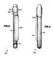
- Figs. 4 and 5 show side views of the earhook 100, where the mounting elements 103 is adjusted in a position substantially planar with the hook element 101.
- the mounting element 103 has a first annular edge 115, which may be configured so as to facilitate mounting of a device on the mounting element 103, such as an earphone.
- the mounting element 103 further comprises a second annular edge 117, which may be adapted to facilitate the mounting of a device in the mounting element 103.
- a second annular edge 117 may be adapted to facilitate the mounting of a device in the mounting element 103.
- one or both of the first and second angular edges 115 and 117 may be configured to abut or engage a portion of an earphone mounted on the mounting element 103, such that the earphone is securely fastened the mounting element 103.
- Slits 119 may be formed in the first connection member 108 to facilitate connection of the hook element 103 such that it is rotatably mounted to the hook element 101. Forming the slits 119 as through openings may be advantageous in that it simplifies the manufacturing process. However, it should be noted that the slits 119 may be formed with different configurations, such as being grooves on the inside of the first connection member 108. The slits 119 may be formed using well-known techniques.
- Fig. 6 shows an embodiment of the first and second connection members 108 and 111.
- the first connection member 108 comprises a substantially cylindrical cavity 123, and slits 119 in the first connection member 108.
- the second connection member 111 comprises a flange 121.
- the flange 121 may, for example, extend around the entire second connection member 111.
- the flange 121 will be used to facilitate mounting of the second connection member 111 inside the first connection member 108. This may, for example, be carried out by the flange 121 engaging the slits 119, thereby securing the second connection member 111 to the first connection member 108, and allowing it to be adjusted into different positions.
- Fig. 7 shows an exemplary cross section of the hook element 101, taken along the line indicated in Fig. 3.
- the hook element 101 comprises a core 127 covered by a body 129.
- the core 127 will act as a flexibly adjustable member which allows the hook element 101 to be flexed into different configurations.
- the core 127 may render the hook element 101 capable of being contoured and thereafter maintaining its shape.
- Many different materials may be used for the core member 127.
- the core member 127 may be a wire with a substantially circular cross section.
- the core member 127 may be an annealed wire.
- the core member 127 may be provided with other cross sections than circular.
- the body 129 may have other cross sectional configurations than the one shown in the drawing.
- the body 129 may have a substantially wedge-like cross section, with rounded edges to make it comfortable to use.
- the core member 127 may constitute a lesser or greater proportion of the entire cross-sectional area of the hook element 101.
- the body 129 may, for example, be a soft plastic material such as a thermoelastic material.
- a thermoelastic material such as a thermoelastic material.
- SANTOPRENE material a material which is a SANTOPRENE material.
- the body 129 is molded to the core member 127, in order to allow it to flexibly conform to any particular configuration in which the core member 127 may be contoured.
- the hook element 101 may be formed entirely from one material which renders it capable of being contoured to the wearer's ear and thereafter maintaining its shape.
- the core member may extend substantially along the entire length of the hook element 101. In another embodiment, it may terminate somewhat before the end of the hook element 101
- part of the hook element 101 may be formed from a hard plastic material, and another part, such as one which comes in contact with the wearer's skin, may be formed from a soft pliable plastic material. This may, for example, allow the hook element 101 to be used with great comfort for the wearer, as well as with adequate rigidity and structural integrity for the intended use.
- the hook element 101 may be molded and/or formed using well known techniques.
- Fig. 8 shows a cross section of the mounting element 103 taken along the line indicated in Fig. 2.
- the first annular edge 115 and the second annular edge 117 have been configured particularly to facilitate the mounting of a device in the mounting element 103, allowing the device to be positioned adjacent the wearer's ear by means of the earhook 100.
- a wearer may place the hook element 101 behind the ear, whereby the mounting element 103 and an earphone mounted thereon are situated approximately in front of the person's ear. If the wearer wishes to adjust the earhook, he or she may contour the hook element 101 to conform to the shape of the ear, whereby the earhook 100 can be worn with a comfortable fit adapted to the person's ear.
- the mounting element may furthermore be contoured before putting on the earhook 100, and the fit may then be adjusted once it is in place.
Abstract
Description
- The invention relates to earhooks, and in particular to flexible earhooks that may be contoured to a wearer's ear.
- Traditionally, earphones have been used by positioning a support member or band across the wearer's head, whereby the earphones rest against the outer vicinity of the ears and the wearer perceives the audio produced in the earphone. When it is desirable for the wearer to be able to perceive also ambient sound and engage in direct conversations, one of the earphones has been replaced by a pad that rests against the side of the head. While perceiving sound through the one earphone which is positioned against one ear, the wearer can still hear ambient sound with the other ear.
- However, the support member extending across the wearer's head has disadvantages. It may product unwanted pressure on the wearer's head, and it may also interfere with the person's hair. Furthermore, some wearers find it uncomfortable having an object extending over the top of their head, further adding to the disadvantages of such structures.
- Prior art earphones which hang from the outer ear (lat. pinna) are not flexible, that is, they are typically made from hard plastic materials which severely restrict the amount of adjustment the wearer can make. This may render the earphone uncomfortable, which may cause the wearer to frequently readjust the earphone for a more comfortable fit.
- Being able to offer the wearer an adjustable earhook allows the wearer to contour the earhook to reflect the shape of the individual wearer's ear. Doing so greatly improves the wearer's comfort, in that the wearer is able to adjust the earhook to a personal comfortable fit. Good adjustability and comfort for the wearer is particularly important in a professional situation where the earphone is intended to be used for extended periods of time.
- Thus, it can be seen that there is a need for an earhook which allows a lightweight, accessible, and easily adjustable arrangement of an earphone close to the wearer's ear.
- The present invention relates generally to earhooks, and in particular to flexible earhooks that may be contoured to a wearer's ear.
- A flexible earhook for positioning an earphone adjacent a wearer's ear comprises a mounting element capable of being provided with the earphone, and a hook element comprising a material capable of being contoured and thereafter maintaining its shape. The hook element and the mounting element may be connected such that the flexible earhook can be used on either ear.
- In one embodiment, the mounting element comprises a hard plastic material. In another embodiment, the hook element comprises a soft pliable plastic material facing the wearer's ear.
- In one embodiment, the longitudinal member includes a curved portion between the first and second ends. In another embodiment, the material capable of being shaped and thereafter maintaining its shape comprises a wire. The wire may be covered with a soft plastic material.
- In yet another embodiment, the hook element and the mounting element are connected by a substantially cylindrical portion on the mounting element and by a hollow, substantially cylindrical housing on the hook element, wherein the cylindrical portion has a radially extending flange, and the housing having a plurality of slits to accommodate the flange.
- These and various other advantages and features of novelty which characterize the present invention are pointed out with particularity in the claims annexed hereto and forming a part hereof. However, for a better understanding of the present invention, its advantages, and other objects obtained by its use, reference should be made to the drawings which form a further part hereof, and to the accompanying descriptive matter, in which preferred embodiments of the present invention are illustrated and described.
- The present invention will be described with reference to the accompanying drawings, wherein like reference numerals identify corresponding or like components.
- Fig. 1 is a perspective view of an embodiment of the present invention;
- Fig. 2 is a front view of the embodiment of the present invention;
- Fig. 3 is a rear view of the embodiment of the present invention;
- Fig. 4 is a first side view of the embodiment of the present invention;
- Fig. 5 is a second side view of the embodiment of the present invention;
- Fig. 6 is a perspective view showing an earhook register of an embodiment in accordance with the present invention;
- Fig. 7 is a cross section of the hook element in the embodiment shown in Fig. 3, taken along line 7-7; and
- Fig. 8 is a cross section of the mounting element in the embodiment shown in Fig. 2, taken along line 8-8.
-
- Fig. 1 shows a
flexible earhook 100 in one embodiment of the present invention. Theearhook 100 generally comprises ahook element 101 and amounting element 103. Thehook element 101 may be used to position theearhook 100 on a wearer's ear. Thehook element 101 may be connected to the mounting element such that theearhook 100 may rotate, that is, theearhook 101 may be used with either left or right ear. Themounting element 103 may be used for mounting an earphone or similar equipment, such that the earphone is positioned adjacent the wearer's ear when wearing theearhook 100. Thehook element 101 is flexibly adjustable, which allows a wearer to adjust it to conform comfortably to the shape of his or her ear. - The
hook element 101 comprises afirst end 105 and asecond end 107. Thehook element 101 further comprises afirst connection member 108 which may, for example, be used for connecting thehook element 101 to themounting element 103. Between thefirst end 105 and thesecond end 107 is a longitudinal portion including acurved portion 106. Thecurved portion 106 may be shaped to make the fitting of theearhook 100 onto the wearer's ear comfortable. - As shown by the
shaded area 112 in Fig. 1, thehook element 101 may comprise one material on portions adjacent the wearer's ear. The material may be a soft pliable plastic material, for example a SANTOPRENE material. This may serve to increase the comfort of using theearhook 100. - In the illustrated embodiment, the
curved portion 106 extends down along the back of thehook element 101. When thecurved portion 106 is formed from a hard plastic material, this may serve to facilitate the wearer's contouring of thehook element 101 in order for theearhook 100 to fit comfortably. Thecurved portion 106 of a hard plastic material may more or less resist flexing when theportion 112 is being contoured, maintaining thecurved portion 106 in substantially original shape. - The
mounting element 103 has a substantially annular shape, and comprises a second connection member 111. In the shown embodiment, the second connection member 111 is positioned substantially radially with respect to themounting element 103. The second connection member 111 will extend into thefirst connection member 108 and together they form anearhook register 110 which allows themounting element 103 to be positioned at angles with respect tohook element 101. This allows, for example, an earphone which may be mounted on themounting element 103, to be adjusted relative to the wearer's ear as desired. As illustrated, theearhook register 110 may be a swivel mechanism. In other embodiments, other configurations such as hinge mechanisms may be used. - The second connection member 111 may have different configurations. For example, in one embodiment the second connection member 111 may enclose the
first connection member 108. - In other embodiments the
mounting element 103 may have a shape suitable for the particular equipment, such as an earphone, which is to be mounted on themounting element 103. It is contemplated that themounting element 103 need not necessarily enclose or cover the earphone etc.; in some embodiments it may comprise a fitting which attaches to the earphone etc. - The mounting
element 103 may be formed using well-known techniques. The mountingelement 103 may comprise, for example, a hard plastic material. An example of such a material is a XENOY material. - Figs. 2 and 3 show front and rear views of the
flexible earhook 100, respectively. In the shown configuration of theearhook 100, thefirst connection member 108 and the second connection member 111 are positioned so that the mountingelement 103 is substantially planar with thehook element 101. The mountingelement 103 is connected to thehook element 101 such as to be rotatably positionable with respect to thehook element 101. Thus, when wearers put on theearhook 100, thehook element 101 and the mountingelement 103 will assume positions with respect to each other. - Figs. 4 and 5 show side views of the
earhook 100, where the mountingelements 103 is adjusted in a position substantially planar with thehook element 101. The mountingelement 103 has a firstannular edge 115, which may be configured so as to facilitate mounting of a device on the mountingelement 103, such as an earphone. - The mounting
element 103 further comprises a secondannular edge 117, which may be adapted to facilitate the mounting of a device in the mountingelement 103. For example, one or both of the first and secondangular edges element 103, such that the earphone is securely fastened the mountingelement 103. -
Slits 119 may be formed in thefirst connection member 108 to facilitate connection of thehook element 103 such that it is rotatably mounted to thehook element 101. Forming theslits 119 as through openings may be advantageous in that it simplifies the manufacturing process. However, it should be noted that theslits 119 may be formed with different configurations, such as being grooves on the inside of thefirst connection member 108. Theslits 119 may be formed using well-known techniques. - Fig. 6 shows an embodiment of the first and
second connection members 108 and 111. Thefirst connection member 108 comprises a substantiallycylindrical cavity 123, and slits 119 in thefirst connection member 108. - The second connection member 111 comprises a
flange 121. Theflange 121 may, for example, extend around the entire second connection member 111. Theflange 121 will be used to facilitate mounting of the second connection member 111 inside thefirst connection member 108. This may, for example, be carried out by theflange 121 engaging theslits 119, thereby securing the second connection member 111 to thefirst connection member 108, and allowing it to be adjusted into different positions. - Fig. 7 shows an exemplary cross section of the
hook element 101, taken along the line indicated in Fig. 3. Thehook element 101 comprises a core 127 covered by abody 129. Thecore 127 will act as a flexibly adjustable member which allows thehook element 101 to be flexed into different configurations. For example, thecore 127 may render thehook element 101 capable of being contoured and thereafter maintaining its shape. Many different materials may be used for thecore member 127. For example, thecore member 127 may be a wire with a substantially circular cross section. As another example, thecore member 127 may be an annealed wire. Thecore member 127 may be provided with other cross sections than circular. Thebody 129 may have other cross sectional configurations than the one shown in the drawing. For example, thebody 129 may have a substantially wedge-like cross section, with rounded edges to make it comfortable to use. It should be noted that thecore member 127 may constitute a lesser or greater proportion of the entire cross-sectional area of thehook element 101. - The
body 129 may, for example, be a soft plastic material such as a thermoelastic material. One example of such a material is a SANTOPRENE material. Thebody 129 is molded to thecore member 127, in order to allow it to flexibly conform to any particular configuration in which thecore member 127 may be contoured. In other embodiments, thehook element 101 may be formed entirely from one material which renders it capable of being contoured to the wearer's ear and thereafter maintaining its shape. - In some embodiments, the core member may extend substantially along the entire length of the
hook element 101. In another embodiment, it may terminate somewhat before the end of thehook element 101 - In some embodiments, part of the
hook element 101 may be formed from a hard plastic material, and another part, such as one which comes in contact with the wearer's skin, may be formed from a soft pliable plastic material. This may, for example, allow thehook element 101 to be used with great comfort for the wearer, as well as with adequate rigidity and structural integrity for the intended use. Thehook element 101 may be molded and/or formed using well known techniques. - Fig. 8 shows a cross section of the mounting
element 103 taken along the line indicated in Fig. 2. In this embodiment, the firstannular edge 115 and the secondannular edge 117 have been configured particularly to facilitate the mounting of a device in the mountingelement 103, allowing the device to be positioned adjacent the wearer's ear by means of theearhook 100. - In an exemplary use of the
earhook 100, a wearer may place thehook element 101 behind the ear, whereby the mountingelement 103 and an earphone mounted thereon are situated approximately in front of the person's ear. If the wearer wishes to adjust the earhook, he or she may contour thehook element 101 to conform to the shape of the ear, whereby theearhook 100 can be worn with a comfortable fit adapted to the person's ear. The mounting element may furthermore be contoured before putting on theearhook 100, and the fit may then be adjusted once it is in place. - While the invention has been described in connection with an embodiment, it will be understood that the invention is not limited to that embodiment. The invention is intended to cover all alternatives, modifications and equivalents as may be included within the spirit and scope thereof, as defined by the appended claims.
Claims (10)
- A flexible earhook for positioning an earphone adjacent a wearer's ear, the flexible earhook comprising:a mounting element capable of being provided with the earphone; anda hook element connected to the mounting element, comprising a material capable of being contoured and thereafter maintaining its shape.
- The flexible earhook in claim 1, wherein the mounting element comprises a hard plastic material.
- The flexible earhook of claim 1, wherein the hook element comprises a soft plastic material.
- The flexible earhook of claim 1, wherein the hook element comprises a soft plastic material on portions facing the wearer's ear.
- The flexible earhook of claim 1, wherein the hook element includes a curved portion.
- The flexible earhook of claim 1, wherein the material capable of being contoured and thereafter maintaining its shape comprises a wire.
- The flexible earhook of claim 1, wherein the hook element and the mounting element are connected by a swivel element.
- The flexible earhook of claim 1, wherein the hook element and the mounting element are connected by a substantially cylindrical portion on the mounting element and by a hollow, substantially cylindrical housing on the hook element, wherein the cylindrical portion has a radially extending flange, and the housing having a plurality of slits to accommodate the flange.
- The flexible earhook of claim 1, wherein the hook element comprises a wire covered by a soft plastic material.
- The flexible earhook of claim 1, wherein the hook element and the mounting element are connected such that the flexible earhook can be used on either ear.
Applications Claiming Priority (2)
| Application Number | Priority Date | Filing Date | Title |
|---|---|---|---|
| US197101 | 1998-11-20 | ||
| US09/197,101 US6418230B1 (en) | 1998-11-20 | 1998-11-20 | Flexible earhook |
Publications (3)
| Publication Number | Publication Date |
|---|---|
| EP1003349A2 true EP1003349A2 (en) | 2000-05-24 |
| EP1003349A3 EP1003349A3 (en) | 2006-05-10 |
| EP1003349B1 EP1003349B1 (en) | 2008-01-23 |
Family
ID=22728059
Family Applications (1)
| Application Number | Title | Priority Date | Filing Date |
|---|---|---|---|
| EP99610057A Expired - Lifetime EP1003349B1 (en) | 1998-11-20 | 1999-10-08 | Flexible earhook |
Country Status (9)
| Country | Link |
|---|---|
| US (2) | US6418230B1 (en) |
| EP (1) | EP1003349B1 (en) |
| JP (1) | JP2000165976A (en) |
| CN (1) | CN1212044C (en) |
| AT (1) | ATE385162T1 (en) |
| AU (1) | AU766207B2 (en) |
| CA (1) | CA2277007A1 (en) |
| DE (1) | DE69938029T2 (en) |
| NO (1) | NO314060B1 (en) |
Cited By (10)
| Publication number | Priority date | Publication date | Assignee | Title |
|---|---|---|---|---|
| DE10046202A1 (en) * | 2000-09-19 | 2002-03-28 | Guenther Manz | Hands free communication headset has ear plug with microphone |
| WO2004023839A2 (en) * | 2002-09-03 | 2004-03-18 | Audisoft Technologies Inc. | Headset for camera |
| WO2004049752A1 (en) * | 2002-11-27 | 2004-06-10 | Gn Netcom A/S | A headset having an attachment element for attaching an ear hook to a holding ring |
| GB2421870A (en) * | 2004-10-19 | 2006-07-05 | Racal Acoustics Ltd | Headset attachment apparatus |
| WO2009106151A1 (en) * | 2008-02-25 | 2009-09-03 | Sony Ericsson Mobile Communications Ab | Adjustable ear-hook earphone with compressible inner portion and related methods |
| WO2009147370A1 (en) * | 2008-06-03 | 2009-12-10 | Racal Acoustics Limited | Earpieces |
| DE10139865C5 (en) * | 2001-08-14 | 2011-01-13 | Palm, Inc. (n.d.Ges. d. Staates Delaware), Sunnyvale | Headset for an electronic device |
| WO2015126659A1 (en) * | 2014-02-20 | 2015-08-27 | Motorola Solutions, Inc. | Adjustable earpiece device |
| EP2974360A4 (en) * | 2013-03-14 | 2016-10-19 | Harman Int Ind | Behind the ear earphone |
| WO2019175194A1 (en) * | 2018-03-12 | 2019-09-19 | Cosinuss Gmbh | Holding device |
Families Citing this family (75)
| Publication number | Priority date | Publication date | Assignee | Title |
|---|---|---|---|---|
| US6418230B1 (en) * | 1998-11-20 | 2002-07-09 | Gn Netcom/Unex Inc. | Flexible earhook |
| JP4103267B2 (en) * | 1999-10-12 | 2008-06-18 | ソニー株式会社 | headphone |
| AT411512B (en) * | 2000-06-30 | 2004-01-26 | Spirit Design Huber Christoffe | HANDSET |
| JP2003078984A (en) * | 2001-08-31 | 2003-03-14 | Pioneer Electronic Corp | Earphone |
| JP2003111180A (en) * | 2001-09-28 | 2003-04-11 | Audio Technica Corp | Headphone system |
| KR200271600Y1 (en) * | 2001-12-18 | 2002-04-12 | 주식회사 잉크테크 | An ear hanger type earphone-mike |
| US7123737B2 (en) * | 2002-02-13 | 2006-10-17 | Plantronics, Inc. | Ear clasp headset |
| US20060153415A1 (en) * | 2005-01-07 | 2006-07-13 | Weyer Frank M | Frame-mountable earphone system |
| US7457643B2 (en) | 2005-03-03 | 2008-11-25 | Steve Farrell | Ear mount assembly for a communication device |
| EP1705949A1 (en) * | 2005-03-22 | 2006-09-27 | Sony Ericsson Mobile Communications AB | An electroacoustic device |
| EP1867277A4 (en) * | 2005-04-08 | 2014-07-09 | Terumo Corp | Sphygmomanometry instrument |
| US7925037B2 (en) * | 2005-10-19 | 2011-04-12 | Sony Ericsson Mobile Communications Ab | Communications headset |
| TWI299237B (en) * | 2005-11-15 | 2008-07-21 | Benq Corp | Communication device |
| US20070169317A1 (en) * | 2006-01-25 | 2007-07-26 | Cindy Gonet | Flexible clip |
| WO2007095572A2 (en) * | 2006-02-14 | 2007-08-23 | Dean Thomas M | Audio earbud carrier |
| US20070223765A1 (en) * | 2006-03-13 | 2007-09-27 | Bluedect Technology Corp. | Wireless headset adjustable for either ear |
| US10291980B2 (en) * | 2006-06-30 | 2019-05-14 | Bose Corporation | Earpiece positioning and retaining |
| US8249287B2 (en) | 2010-08-16 | 2012-08-21 | Bose Corporation | Earpiece positioning and retaining |
| US20080178088A1 (en) * | 2006-07-27 | 2008-07-24 | Personics Holdings Inc. | Method and device of customizing headphones |
| JP4289376B2 (en) | 2006-08-18 | 2009-07-01 | ソニー株式会社 | headset |
| TWM333023U (en) * | 2007-06-05 | 2008-05-21 | Hsin-Yuan Kuo | Stereophonic earphone |
| US8428289B2 (en) * | 2007-06-13 | 2013-04-23 | Innovelis, Inc. | Headphone adaptation and positioning device |
| US8121320B2 (en) * | 2008-01-11 | 2012-02-21 | Songbird Hearing, Inc. | Hearing aid |
| US20090226024A1 (en) * | 2008-02-04 | 2009-09-10 | Dean Thomas M | Speaker enclosure and headphone |
| US7945043B1 (en) | 2008-03-25 | 2011-05-17 | Yazzie Jr Eddie R | Hands-free telephone holder |
| CA2720785C (en) | 2008-04-07 | 2015-05-12 | Koss Corporation | Wireless earphone that transitions between wireless networks |
| US20090285434A1 (en) * | 2008-05-13 | 2009-11-19 | Jason Martin Williams | Earhook and earbud headset |
| USD618669S1 (en) * | 2009-04-06 | 2010-06-29 | Koss Corporation | Earphone |
| JP5399482B2 (en) | 2008-05-19 | 2014-01-29 | コス コーポレイション | Adjustable dual speaker element type in-ear earphone |
| US20090316942A1 (en) * | 2008-06-19 | 2009-12-24 | Huang Chung-Yi | Headset and Method for Collecting same |
| US20100061581A1 (en) * | 2008-09-09 | 2010-03-11 | Creative Technology Ltd | Sound producing device |
| US20100086165A1 (en) * | 2008-10-07 | 2010-04-08 | Dwayne Wilson | Universal Earbud Adapter |
| US8019111B2 (en) * | 2008-11-03 | 2011-09-13 | Arian Soheili | Interchangeable headphone earhook support |
| US8442252B2 (en) | 2010-09-30 | 2013-05-14 | Audiotoniq, Inc. | Behind-the-ear hearing aid with interchangeable ear hook and ear tube |
| US20120243723A1 (en) * | 2011-03-25 | 2012-09-27 | Savox Communications Oy Ab (Ltd) | Earphone with a support element |
| JP5527282B2 (en) * | 2011-05-23 | 2014-06-18 | 株式会社Jvcケンウッド | Ear hanger and earphone equipped with the same |
| US8737669B2 (en) | 2011-07-28 | 2014-05-27 | Bose Corporation | Earpiece passive noise attenuating |
| CN102647649B (en) * | 2012-05-29 | 2014-07-23 | 全南三扬电子有限公司 | In-ear headset |
| US9602909B2 (en) | 2013-06-20 | 2017-03-21 | Google Technology Holdings LLC | Wireless communication earpiece |
| US9521478B2 (en) * | 2013-07-03 | 2016-12-13 | Google Technology Holdings LLC | Three-piece device ear hook |
| USD786834S1 (en) * | 2014-01-31 | 2017-05-16 | Gn Netcom A/S | Earphone |
| USD734744S1 (en) * | 2014-05-15 | 2015-07-21 | Apple Inc. | Audio listening system |
| USD754638S1 (en) * | 2014-08-05 | 2016-04-26 | The Ketchum Group, Inc. | Ear cushion for earphone assembly |
| US10003878B2 (en) * | 2014-08-15 | 2018-06-19 | Alexey Leonidovich Ushakov | In-the-ear earphone, its variations and methods of wearing the earphone |
| US10063958B2 (en) | 2014-11-07 | 2018-08-28 | Microsoft Technology Licensing, Llc | Earpiece attachment devices |
| JP1529615S (en) * | 2014-12-25 | 2015-07-27 | ||
| TWD176082S (en) * | 2014-12-29 | 2016-06-01 | 三星電子股份有限公司 | Portion of cap for earphone |
| USD816051S1 (en) * | 2015-02-04 | 2018-04-24 | Orion Labs | Wearable communication device |
| USD765259S1 (en) | 2015-02-19 | 2016-08-30 | Brainscope Company, Inc. | Ear attachment for medical headset |
| USD773438S1 (en) * | 2015-08-05 | 2016-12-06 | Harman International Industries, Incorporated | Headphone |
| US10405079B2 (en) * | 2015-08-07 | 2019-09-03 | New Audio LLC | Audio headset having arm-to-yoke coupling features and related technology |
| US9716937B2 (en) * | 2015-09-16 | 2017-07-25 | Apple Inc. | Earbuds with biometric sensing |
| US10856068B2 (en) | 2015-09-16 | 2020-12-01 | Apple Inc. | Earbuds |
| USD779461S1 (en) * | 2015-10-08 | 2017-02-21 | Surefire, Llc | Earpiece |
| USD796485S1 (en) * | 2015-12-29 | 2017-09-05 | Harman International Industries, Incorporated | Pair of headphones |
| USD835064S1 (en) * | 2016-01-15 | 2018-12-04 | Sony Corporation | Headphone |
| USD903630S1 (en) | 2016-02-29 | 2020-12-01 | Sony Corporation | Earphone |
| USD819594S1 (en) * | 2016-02-29 | 2018-06-05 | Sony Corporation | Earphone |
| USD845281S1 (en) * | 2016-04-21 | 2019-04-09 | Gn Audio A/S | Earbud |
| US9807493B1 (en) | 2016-04-21 | 2017-10-31 | Human, Incorporated | Attachment apparatus |
| WO2018048846A1 (en) | 2016-09-06 | 2018-03-15 | Apple Inc. | Earphone assemblies with wingtips for anchoring to a user |
| USD859368S1 (en) * | 2017-12-13 | 2019-09-10 | Dongguan Homeesen Electronic Technology Co., Ltd. | Note ear hanger |
| USD869444S1 (en) * | 2018-07-19 | 2019-12-10 | Airmojo Audio Inc | Ear loop |
| USD881163S1 (en) * | 2018-10-25 | 2020-04-14 | Logitech Europe S.A. | Earphone fin |
| USD906294S1 (en) * | 2019-01-28 | 2020-12-29 | Compal Electronics, Inc. | Set of earbuds |
| US10924838B1 (en) * | 2019-09-11 | 2021-02-16 | Bose Corporation | Audio device |
| JP2021078071A (en) * | 2019-11-13 | 2021-05-20 | 株式会社Jvcケンウッド | earphone |
| USD879747S1 (en) * | 2019-11-26 | 2020-03-31 | elago CO. LTD | Earhook for earphone |
| USD879748S1 (en) * | 2020-01-06 | 2020-03-31 | elago CO. LTD | Earhook for earphone |
| USD940689S1 (en) * | 2020-03-04 | 2022-01-11 | Luxshare Precision Industry Co., Ltd. | Wireless headset |
| TWM604178U (en) * | 2020-05-28 | 2020-11-21 | 國防醫學院 | Ear physiological wearable device |
| US11863928B2 (en) * | 2020-11-12 | 2024-01-02 | Gn Hearing A/S | Retaining member for earpiece of hearing device |
| USD978113S1 (en) * | 2021-03-28 | 2023-02-14 | Cheng Uei Precision Industry Co., Ltd. | Earphone |
| USD993940S1 (en) * | 2021-05-18 | 2023-08-01 | Dongguan Edifier Technology Co., Ltd. | Pair of wingtips for earphones |
| USD997919S1 (en) * | 2021-09-29 | 2023-09-05 | Bose Corporation | Stability band for earbud |
Citations (8)
| Publication number | Priority date | Publication date | Assignee | Title |
|---|---|---|---|---|
| US2513746A (en) * | 1947-02-10 | 1950-07-04 | Carl P Rohr | Hearing aid support |
| GB2239162A (en) * | 1989-10-14 | 1991-06-26 | David Anthony Batten | Flexible earphone band |
| DE4329635A1 (en) * | 1993-09-02 | 1995-03-09 | Sennheiser Electronic | Device for attaching an electroacoustic transducer to an ear on one side |
| US5450496A (en) * | 1993-07-30 | 1995-09-12 | Acs Communications, Inc. | Communications headset having a detachable receiver capsule and cable pivot |
| EP0690654A2 (en) * | 1994-06-30 | 1996-01-03 | Peavey Electronics Corp. | Ergonomic ear-mounted headset |
| EP0749263A2 (en) * | 1995-06-13 | 1996-12-18 | Gn Netcom A/S | Headset with adjustable earhook |
| WO1997027721A1 (en) * | 1996-01-26 | 1997-07-31 | Veijo Sakari Makkonen | Headset and method for a headset |
| US5790683A (en) * | 1994-06-17 | 1998-08-04 | Salzani; Augusto | Headphone including split earphones and coupling means for coupling it to the ears |
Family Cites Families (53)
| Publication number | Priority date | Publication date | Assignee | Title |
|---|---|---|---|---|
| DE436377C (en) | 1925-03-15 | 1926-10-30 | Siemens & Halske Akt Ges | Arrangement for fastening ear telephones |
| US1587643A (en) | 1925-06-02 | 1926-06-08 | Dictograph Products Corp | Ear-loop attachment for deaf phones |
| US2485405A (en) | 1944-04-21 | 1949-10-18 | Stromberg Carlson Co | Dipole microphone |
| US2506490A (en) | 1946-08-30 | 1950-05-02 | William R Coley | Earpiece with plural sound passages |
| US2481387A (en) | 1947-04-07 | 1949-09-06 | Archie O Bonecutter | Telephone holder |
| US2474135A (en) | 1947-06-05 | 1949-06-21 | Gray Mfg Co | Adjustable earpiece support |
| US2586644A (en) | 1949-02-10 | 1952-02-19 | Telex Inc | Headset |
| US2606255A (en) | 1949-11-29 | 1952-08-05 | Lester P Burrow | Telephone receiver holder |
| US2939923A (en) | 1955-08-03 | 1960-06-07 | John D Henderson | Hearing aid plastic ear pieces |
| NL212819A (en) * | 1955-12-13 | 1900-01-01 | Zenith Radio Corp | |
| US3440365A (en) | 1965-11-04 | 1969-04-22 | Bell Telephone Labor Inc | Telephone headset with adjustable speech tube |
| AT297111B (en) | 1970-04-08 | 1972-03-10 | Akg Akustische Kino Geraete | Headband for headphones |
| US3682378A (en) * | 1970-11-23 | 1972-08-08 | Pitney Bowes Inc | Value dispensing mechanisms |
| GB1377237A (en) | 1972-09-13 | 1974-12-11 | Standard Telephones Cables Ltd | Telephone headset |
| US3862378A (en) | 1973-12-06 | 1975-01-21 | J Ray Norris | Ear set |
| US3993879A (en) | 1975-03-24 | 1976-11-23 | Wallace Keith Larkin | Acoustical communications headset |
| US4020297A (en) | 1976-01-15 | 1977-04-26 | Brodie S Dan | Adjustable headset |
| US4048453A (en) | 1976-02-11 | 1977-09-13 | Gustave Seidel | Telephone handset support device |
| GB2036505B (en) | 1978-11-16 | 1983-04-13 | Zichy T | Ear-supported microphone |
| US4273969A (en) | 1979-06-01 | 1981-06-16 | Roanwell Corporation | Communications headset mountable over the ear |
| US4335281A (en) | 1980-06-24 | 1982-06-15 | Plantronics, Inc. | Post-auricle contoured headset for two-way voice communication |
| USD272904S (en) | 1981-02-17 | 1984-03-06 | Sony Corporation | Earphone |
| JPS641833Y2 (en) | 1981-03-10 | 1989-01-17 | ||
| JPS6010999A (en) | 1983-06-30 | 1985-01-21 | Seiko Instr & Electronics Ltd | Acoustic transducer |
| NL8400925A (en) | 1984-03-23 | 1985-10-16 | Philips Nv | HEARING AID, IN PARTICULAR BEHIND-THE-EAR HEARING AID. |
| US4763753A (en) | 1984-07-05 | 1988-08-16 | Etymotic Research, Inc. | Insert earphones for audiometry |
| USD293107S (en) | 1985-04-26 | 1987-12-08 | AS Electronics AG | Radio |
| USD293197S (en) * | 1985-05-03 | 1987-12-15 | Schumacher Edwin A | Bottle opener |
| US4720857A (en) | 1985-12-06 | 1988-01-19 | Plantronics, Inc. | Miniaturized headset for two-way voice communication |
| US4702345A (en) | 1986-07-21 | 1987-10-27 | Janssen Gwen V | Hearing aid retention device |
| USD311521S (en) | 1987-09-30 | 1990-10-23 | Gn Netcom A/S | Combined earphone and microphone |
| DK157282C (en) | 1987-09-30 | 1990-05-07 | Gn Netcom As | THE HEADPHONE PHONE WITH ANGLE HOOK AND EQUIPPED TO BE BEARED ON THE OUTER OVER |
| US4875233A (en) | 1987-10-16 | 1989-10-17 | Derhaag Robert L | Headset construction and method of making same |
| DK159748C (en) | 1988-07-01 | 1991-04-29 | Joergen Weber Jensen | HEADPHONE WITH MICROPHONE |
| WO1990010361A1 (en) | 1989-02-28 | 1990-09-07 | Johan Ullman | Headset |
| USD326653S (en) | 1989-12-12 | 1992-06-02 | Sony Corporation | Radio receiver |
| US5210792A (en) * | 1990-08-13 | 1993-05-11 | Matsushita Electric Industrial Co., Ltd. | Ear-hang type headset |
| US5298692A (en) | 1990-11-09 | 1994-03-29 | Kabushiki Kaisha Pilot | Earpiece for insertion in an ear canal, and an earphone, microphone, and earphone/microphone combination comprising the same |
| CN2098773U (en) | 1991-05-16 | 1992-03-11 | 王新生 | Frame-type earphone |
| US5412736A (en) * | 1992-03-23 | 1995-05-02 | Keliiliki; Shawn P. | Personal audio system and earphone for same |
| US5446788A (en) | 1992-09-29 | 1995-08-29 | Unex Corporation | Adjustable telephone headset |
| US5446736A (en) * | 1993-10-07 | 1995-08-29 | Ast Research, Inc. | Method and apparatus for connecting a node to a wireless network using a standard protocol |
| USD357479S (en) | 1993-12-16 | 1995-04-18 | U.S. Philips Corporation | Earphone |
| US5796821A (en) | 1994-01-05 | 1998-08-18 | Crouch; Shirley Aline | Hearing aid telephone interconnect system |
| US5625171A (en) | 1995-05-09 | 1997-04-29 | Marshall; Christina M. | Interchangeable earpiece for stereo listening |
| USD375313S (en) | 1995-06-13 | 1996-11-05 | Gn Netcom A/S | Headset with adjustable earhook |
| US5606621A (en) * | 1995-06-14 | 1997-02-25 | Siemens Hearing Instruments, Inc. | Hybrid behind-the-ear and completely-in-canal hearing aid |
| USD385272S (en) | 1996-06-21 | 1997-10-21 | Acs Wireless, Inc. | Communication headset |
| CA2194641C (en) * | 1996-12-28 | 2005-05-03 | Bill Yang | In-ear type earphone having an ear hanger |
| JP3826478B2 (en) * | 1997-03-13 | 2006-09-27 | ソニー株式会社 | Headphone device |
| USD403327S (en) | 1997-09-23 | 1998-12-29 | Plantronics, Inc. | Convertible earhook headset |
| US5881161A (en) * | 1998-06-17 | 1999-03-09 | Merry Electronics Co., Ltd. | Headphone |
| US6418230B1 (en) * | 1998-11-20 | 2002-07-09 | Gn Netcom/Unex Inc. | Flexible earhook |
-
1998
- 1998-11-20 US US09/197,101 patent/US6418230B1/en not_active Expired - Fee Related
-
1999
- 1999-07-08 CA CA002277007A patent/CA2277007A1/en not_active Abandoned
- 1999-10-05 NO NO19994840A patent/NO314060B1/en unknown
- 1999-10-07 AU AU53533/99A patent/AU766207B2/en not_active Ceased
- 1999-10-08 EP EP99610057A patent/EP1003349B1/en not_active Expired - Lifetime
- 1999-10-08 AT AT99610057T patent/ATE385162T1/en not_active IP Right Cessation
- 1999-10-08 DE DE69938029T patent/DE69938029T2/en not_active Expired - Lifetime
- 1999-11-05 JP JP11315026A patent/JP2000165976A/en active Pending
- 1999-11-18 CN CN99123948.2A patent/CN1212044C/en not_active Expired - Fee Related
-
2001
- 2001-11-05 US US10/013,028 patent/US6914997B2/en not_active Expired - Lifetime
Patent Citations (8)
| Publication number | Priority date | Publication date | Assignee | Title |
|---|---|---|---|---|
| US2513746A (en) * | 1947-02-10 | 1950-07-04 | Carl P Rohr | Hearing aid support |
| GB2239162A (en) * | 1989-10-14 | 1991-06-26 | David Anthony Batten | Flexible earphone band |
| US5450496A (en) * | 1993-07-30 | 1995-09-12 | Acs Communications, Inc. | Communications headset having a detachable receiver capsule and cable pivot |
| DE4329635A1 (en) * | 1993-09-02 | 1995-03-09 | Sennheiser Electronic | Device for attaching an electroacoustic transducer to an ear on one side |
| US5790683A (en) * | 1994-06-17 | 1998-08-04 | Salzani; Augusto | Headphone including split earphones and coupling means for coupling it to the ears |
| EP0690654A2 (en) * | 1994-06-30 | 1996-01-03 | Peavey Electronics Corp. | Ergonomic ear-mounted headset |
| EP0749263A2 (en) * | 1995-06-13 | 1996-12-18 | Gn Netcom A/S | Headset with adjustable earhook |
| WO1997027721A1 (en) * | 1996-01-26 | 1997-07-31 | Veijo Sakari Makkonen | Headset and method for a headset |
Cited By (17)
| Publication number | Priority date | Publication date | Assignee | Title |
|---|---|---|---|---|
| DE10046202A1 (en) * | 2000-09-19 | 2002-03-28 | Guenther Manz | Hands free communication headset has ear plug with microphone |
| DE10139865C5 (en) * | 2001-08-14 | 2011-01-13 | Palm, Inc. (n.d.Ges. d. Staates Delaware), Sunnyvale | Headset for an electronic device |
| WO2004023839A2 (en) * | 2002-09-03 | 2004-03-18 | Audisoft Technologies Inc. | Headset for camera |
| WO2004023839A3 (en) * | 2002-09-03 | 2004-07-01 | Audisoft Technologies Inc | Headset for camera |
| US7209177B2 (en) | 2002-09-03 | 2007-04-24 | Audisoft | Headset for camera |
| WO2004049752A1 (en) * | 2002-11-27 | 2004-06-10 | Gn Netcom A/S | A headset having an attachment element for attaching an ear hook to a holding ring |
| US7978870B2 (en) | 2004-10-19 | 2011-07-12 | Racal Acoustics Limited | Attachment apparatus |
| GB2421870A (en) * | 2004-10-19 | 2006-07-05 | Racal Acoustics Ltd | Headset attachment apparatus |
| GB2421870B (en) * | 2004-10-19 | 2007-08-15 | Racal Acoustics Ltd | Attachment apparatus |
| WO2009106151A1 (en) * | 2008-02-25 | 2009-09-03 | Sony Ericsson Mobile Communications Ab | Adjustable ear-hook earphone with compressible inner portion and related methods |
| WO2009147370A1 (en) * | 2008-06-03 | 2009-12-10 | Racal Acoustics Limited | Earpieces |
| EP2974360A4 (en) * | 2013-03-14 | 2016-10-19 | Harman Int Ind | Behind the ear earphone |
| WO2015126659A1 (en) * | 2014-02-20 | 2015-08-27 | Motorola Solutions, Inc. | Adjustable earpiece device |
| GB2537781A (en) * | 2014-02-20 | 2016-10-26 | Motorola Solutions Inc | Adjustable earpiece device |
| GB2537781B (en) * | 2014-02-20 | 2021-05-05 | Motorola Solutions Inc | Adjustable earpiece device |
| WO2019175194A1 (en) * | 2018-03-12 | 2019-09-19 | Cosinuss Gmbh | Holding device |
| US11375308B2 (en) | 2018-03-12 | 2022-06-28 | Cosinuss Gmbh | Holding device |
Also Published As
| Publication number | Publication date |
|---|---|
| DE69938029T2 (en) | 2009-02-12 |
| US6418230B1 (en) | 2002-07-09 |
| AU5353399A (en) | 2000-05-25 |
| US6914997B2 (en) | 2005-07-05 |
| NO994840L (en) | 2000-05-22 |
| ATE385162T1 (en) | 2008-02-15 |
| CN1212044C (en) | 2005-07-20 |
| NO994840D0 (en) | 1999-10-05 |
| US20020041697A1 (en) | 2002-04-11 |
| CA2277007A1 (en) | 2000-05-20 |
| JP2000165976A (en) | 2000-06-16 |
| DE69938029D1 (en) | 2008-03-13 |
| AU766207B2 (en) | 2003-10-09 |
| NO314060B1 (en) | 2003-01-20 |
| CN1268014A (en) | 2000-09-27 |
| EP1003349B1 (en) | 2008-01-23 |
| EP1003349A3 (en) | 2006-05-10 |
Similar Documents
| Publication | Publication Date | Title |
|---|---|---|
| EP1003349B1 (en) | Flexible earhook | |
| US6320960B1 (en) | Headset with adjustable earpiece | |
| US4529058A (en) | Earphones | |
| US8428289B2 (en) | Headphone adaptation and positioning device | |
| RU2489998C2 (en) | Headband-free hearing protector, and method for hearing protection | |
| US6690808B2 (en) | Personal earphone assembly for mounting upon eyeglasses | |
| US4791673A (en) | Bone conduction audio listening device and method | |
| US9055365B2 (en) | Earbuds securable to users' outer ears and related headphone systems and methods | |
| USRE35051E (en) | Combination multiple supported variable position audio intake control devices | |
| US4554993A (en) | Inflight headset for civil aircraft | |
| US20080298626A1 (en) | Audio earbud carrier | |
| JPH0521593U (en) | Head set | |
| JPH0833079A (en) | Human engineering ear hanging head set | |
| US20240007778A1 (en) | In-ear earpiece retaining structure | |
| EP1050286B1 (en) | Multi-position banded earmuff | |
| KR100904026B1 (en) | Receiving set | |
| KR200319618Y1 (en) | A Control Device of Backphone headband | |
| JPH04216299A (en) | Headphone | |
| JPH04177997A (en) | Ear mount type handset | |
| JPH054696U (en) | Headphone | |
| JP2000073219A (en) | Accessory for hair of head | |
| KR20000005674U (en) | Head set for communication |
Legal Events
| Date | Code | Title | Description |
|---|---|---|---|
| PUAI | Public reference made under article 153(3) epc to a published international application that has entered the european phase |
Free format text: ORIGINAL CODE: 0009012 |
|
| AK | Designated contracting states |
Kind code of ref document: A2 Designated state(s): AT BE CH CY DE DK ES FI FR GB GR IE IT LI LU MC NL PT SE |
|
| AX | Request for extension of the european patent |
Free format text: AL;LT;LV;MK;RO;SI |
|
| PUAL | Search report despatched |
Free format text: ORIGINAL CODE: 0009013 |
|
| AK | Designated contracting states |
Kind code of ref document: A3 Designated state(s): AT BE CH CY DE DK ES FI FR GB GR IE IT LI LU MC NL PT SE |
|
| AX | Request for extension of the european patent |
Extension state: AL LT LV MK RO SI |
|
| 17P | Request for examination filed |
Effective date: 20061110 |
|
| AKX | Designation fees paid |
Designated state(s): AT BE CH CY DE DK ES FI FR GB GR IE IT LI LU MC NL PT SE |
|
| GRAP | Despatch of communication of intention to grant a patent |
Free format text: ORIGINAL CODE: EPIDOSNIGR1 |
|
| GRAS | Grant fee paid |
Free format text: ORIGINAL CODE: EPIDOSNIGR3 |
|
| GRAA | (expected) grant |
Free format text: ORIGINAL CODE: 0009210 |
|
| AK | Designated contracting states |
Kind code of ref document: B1 Designated state(s): AT BE CH CY DE DK ES FI FR GB GR IE IT LI LU MC NL PT SE |
|
| REG | Reference to a national code |
Ref country code: GB Ref legal event code: FG4D |
|
| REG | Reference to a national code |
Ref country code: CH Ref legal event code: EP |
|
| REG | Reference to a national code |
Ref country code: IE Ref legal event code: FG4D |
|
| REF | Corresponds to: |
Ref document number: 69938029 Country of ref document: DE Date of ref document: 20080313 Kind code of ref document: P |
|
| NLV1 | Nl: lapsed or annulled due to failure to fulfill the requirements of art. 29p and 29m of the patents act | ||
| PG25 | Lapsed in a contracting state [announced via postgrant information from national office to epo] |
Ref country code: LI Free format text: LAPSE BECAUSE OF FAILURE TO SUBMIT A TRANSLATION OF THE DESCRIPTION OR TO PAY THE FEE WITHIN THE PRESCRIBED TIME-LIMIT Effective date: 20080123 Ref country code: FI Free format text: LAPSE BECAUSE OF FAILURE TO SUBMIT A TRANSLATION OF THE DESCRIPTION OR TO PAY THE FEE WITHIN THE PRESCRIBED TIME-LIMIT Effective date: 20080123 Ref country code: ES Free format text: LAPSE BECAUSE OF FAILURE TO SUBMIT A TRANSLATION OF THE DESCRIPTION OR TO PAY THE FEE WITHIN THE PRESCRIBED TIME-LIMIT Effective date: 20080504 Ref country code: CH Free format text: LAPSE BECAUSE OF FAILURE TO SUBMIT A TRANSLATION OF THE DESCRIPTION OR TO PAY THE FEE WITHIN THE PRESCRIBED TIME-LIMIT Effective date: 20080123 |
|
| REG | Reference to a national code |
Ref country code: CH Ref legal event code: PL |
|
| PG25 | Lapsed in a contracting state [announced via postgrant information from national office to epo] |
Ref country code: AT Free format text: LAPSE BECAUSE OF FAILURE TO SUBMIT A TRANSLATION OF THE DESCRIPTION OR TO PAY THE FEE WITHIN THE PRESCRIBED TIME-LIMIT Effective date: 20080123 |
|
| ET | Fr: translation filed | ||
| PG25 | Lapsed in a contracting state [announced via postgrant information from national office to epo] |
Ref country code: PT Free format text: LAPSE BECAUSE OF FAILURE TO SUBMIT A TRANSLATION OF THE DESCRIPTION OR TO PAY THE FEE WITHIN THE PRESCRIBED TIME-LIMIT Effective date: 20080623 Ref country code: BE Free format text: LAPSE BECAUSE OF FAILURE TO SUBMIT A TRANSLATION OF THE DESCRIPTION OR TO PAY THE FEE WITHIN THE PRESCRIBED TIME-LIMIT Effective date: 20080123 |
|
| PG25 | Lapsed in a contracting state [announced via postgrant information from national office to epo] |
Ref country code: SE Free format text: LAPSE BECAUSE OF FAILURE TO SUBMIT A TRANSLATION OF THE DESCRIPTION OR TO PAY THE FEE WITHIN THE PRESCRIBED TIME-LIMIT Effective date: 20080423 Ref country code: NL Free format text: LAPSE BECAUSE OF FAILURE TO SUBMIT A TRANSLATION OF THE DESCRIPTION OR TO PAY THE FEE WITHIN THE PRESCRIBED TIME-LIMIT Effective date: 20080123 Ref country code: DK Free format text: LAPSE BECAUSE OF FAILURE TO SUBMIT A TRANSLATION OF THE DESCRIPTION OR TO PAY THE FEE WITHIN THE PRESCRIBED TIME-LIMIT Effective date: 20080123 |
|
| PLBE | No opposition filed within time limit |
Free format text: ORIGINAL CODE: 0009261 |
|
| STAA | Information on the status of an ep patent application or granted ep patent |
Free format text: STATUS: NO OPPOSITION FILED WITHIN TIME LIMIT |
|
| 26N | No opposition filed |
Effective date: 20081024 |
|
| PGFP | Annual fee paid to national office [announced via postgrant information from national office to epo] |
Ref country code: FR Payment date: 20080930 Year of fee payment: 10 |
|
| PG25 | Lapsed in a contracting state [announced via postgrant information from national office to epo] |
Ref country code: MC Free format text: LAPSE BECAUSE OF NON-PAYMENT OF DUE FEES Effective date: 20081031 |
|
| PG25 | Lapsed in a contracting state [announced via postgrant information from national office to epo] |
Ref country code: CY Free format text: LAPSE BECAUSE OF FAILURE TO SUBMIT A TRANSLATION OF THE DESCRIPTION OR TO PAY THE FEE WITHIN THE PRESCRIBED TIME-LIMIT Effective date: 20080123 |
|
| PG25 | Lapsed in a contracting state [announced via postgrant information from national office to epo] |
Ref country code: IT Free format text: LAPSE BECAUSE OF FAILURE TO SUBMIT A TRANSLATION OF THE DESCRIPTION OR TO PAY THE FEE WITHIN THE PRESCRIBED TIME-LIMIT Effective date: 20080123 |
|
| PG25 | Lapsed in a contracting state [announced via postgrant information from national office to epo] |
Ref country code: IE Free format text: LAPSE BECAUSE OF NON-PAYMENT OF DUE FEES Effective date: 20081008 |
|
| PG25 | Lapsed in a contracting state [announced via postgrant information from national office to epo] |
Ref country code: LU Free format text: LAPSE BECAUSE OF NON-PAYMENT OF DUE FEES Effective date: 20081008 |
|
| REG | Reference to a national code |
Ref country code: FR Ref legal event code: ST Effective date: 20100630 |
|
| PG25 | Lapsed in a contracting state [announced via postgrant information from national office to epo] |
Ref country code: FR Free format text: LAPSE BECAUSE OF NON-PAYMENT OF DUE FEES Effective date: 20091102 |
|
| PG25 | Lapsed in a contracting state [announced via postgrant information from national office to epo] |
Ref country code: GR Free format text: LAPSE BECAUSE OF FAILURE TO SUBMIT A TRANSLATION OF THE DESCRIPTION OR TO PAY THE FEE WITHIN THE PRESCRIBED TIME-LIMIT Effective date: 20080424 |
|
| PGFP | Annual fee paid to national office [announced via postgrant information from national office to epo] |
Ref country code: DE Payment date: 20121025 Year of fee payment: 14 |
|
| REG | Reference to a national code |
Ref country code: DE Ref legal event code: R119 Ref document number: 69938029 Country of ref document: DE Effective date: 20140501 |
|
| PG25 | Lapsed in a contracting state [announced via postgrant information from national office to epo] |
Ref country code: DE Free format text: LAPSE BECAUSE OF NON-PAYMENT OF DUE FEES Effective date: 20140501 |
|
| PGFP | Annual fee paid to national office [announced via postgrant information from national office to epo] |
Ref country code: GB Payment date: 20141022 Year of fee payment: 16 |
|
| GBPC | Gb: european patent ceased through non-payment of renewal fee |
Effective date: 20151008 |
|
| PG25 | Lapsed in a contracting state [announced via postgrant information from national office to epo] |
Ref country code: GB Free format text: LAPSE BECAUSE OF NON-PAYMENT OF DUE FEES Effective date: 20151008 |