EP1005034B1 - An optical disk carrying barcoded information - Google Patents
An optical disk carrying barcoded information Download PDFInfo
- Publication number
- EP1005034B1 EP1005034B1 EP00101775A EP00101775A EP1005034B1 EP 1005034 B1 EP1005034 B1 EP 1005034B1 EP 00101775 A EP00101775 A EP 00101775A EP 00101775 A EP00101775 A EP 00101775A EP 1005034 B1 EP1005034 B1 EP 1005034B1
- Authority
- EP
- European Patent Office
- Prior art keywords
- disk
- barcode
- signal
- optical disk
- recording
- Prior art date
- Legal status (The legal status is an assumption and is not a legal conclusion. Google has not performed a legal analysis and makes no representation as to the accuracy of the status listed.)
- Expired - Lifetime
Links
- 230000003287 optical effect Effects 0.000 title claims description 90
- 238000002310 reflectometry Methods 0.000 claims description 26
- 238000000034 method Methods 0.000 description 62
- 239000010410 layer Substances 0.000 description 44
- 230000008569 process Effects 0.000 description 34
- 238000009966 trimming Methods 0.000 description 32
- 238000010586 diagram Methods 0.000 description 30
- 238000004519 manufacturing process Methods 0.000 description 20
- 230000000694 effects Effects 0.000 description 19
- 239000000758 substrate Substances 0.000 description 15
- 229910052782 aluminium Inorganic materials 0.000 description 14
- XAGFODPZIPBFFR-UHFFFAOYSA-N aluminium Chemical compound [Al] XAGFODPZIPBFFR-UHFFFAOYSA-N 0.000 description 14
- 238000001514 detection method Methods 0.000 description 10
- 239000011241 protective layer Substances 0.000 description 10
- 239000012790 adhesive layer Substances 0.000 description 6
- 239000002356 single layer Substances 0.000 description 6
- 238000010276 construction Methods 0.000 description 5
- 238000002474 experimental method Methods 0.000 description 5
- AZDRQVAHHNSJOQ-UHFFFAOYSA-N alumane Chemical group [AlH3] AZDRQVAHHNSJOQ-UHFFFAOYSA-N 0.000 description 4
- 230000015572 biosynthetic process Effects 0.000 description 4
- 230000002265 prevention Effects 0.000 description 4
- 238000012937 correction Methods 0.000 description 3
- 239000010931 gold Substances 0.000 description 3
- 238000001000 micrograph Methods 0.000 description 3
- 238000012545 processing Methods 0.000 description 3
- 230000008901 benefit Effects 0.000 description 2
- 230000005540 biological transmission Effects 0.000 description 2
- 230000007613 environmental effect Effects 0.000 description 2
- PCHJSUWPFVWCPO-UHFFFAOYSA-N gold Chemical compound [Au] PCHJSUWPFVWCPO-UHFFFAOYSA-N 0.000 description 2
- 229910052737 gold Inorganic materials 0.000 description 2
- 238000002844 melting Methods 0.000 description 2
- 230000008018 melting Effects 0.000 description 2
- 239000011347 resin Substances 0.000 description 2
- 229920005989 resin Polymers 0.000 description 2
- 238000007650 screen-printing Methods 0.000 description 2
- 230000004075 alteration Effects 0.000 description 1
- 230000008859 change Effects 0.000 description 1
- 238000006243 chemical reaction Methods 0.000 description 1
- 238000005520 cutting process Methods 0.000 description 1
- 230000001419 dependent effect Effects 0.000 description 1
- 238000000151 deposition Methods 0.000 description 1
- 230000008570 general process Effects 0.000 description 1
- 238000010438 heat treatment Methods 0.000 description 1
- 239000012943 hotmelt Substances 0.000 description 1
- 238000010030 laminating Methods 0.000 description 1
- 238000010330 laser marking Methods 0.000 description 1
- 239000000463 material Substances 0.000 description 1
- 238000005259 measurement Methods 0.000 description 1
- 229910052751 metal Inorganic materials 0.000 description 1
- 239000002184 metal Substances 0.000 description 1
- 238000007645 offset printing Methods 0.000 description 1
- 229920000515 polycarbonate Polymers 0.000 description 1
- 239000004417 polycarbonate Substances 0.000 description 1
- 238000003825 pressing Methods 0.000 description 1
- 230000005855 radiation Effects 0.000 description 1
- 230000000630 rising effect Effects 0.000 description 1
- 238000007493 shaping process Methods 0.000 description 1
- 239000002904 solvent Substances 0.000 description 1
- 238000004528 spin coating Methods 0.000 description 1
- 238000003860 storage Methods 0.000 description 1
- 238000012360 testing method Methods 0.000 description 1
- 238000012546 transfer Methods 0.000 description 1
- 230000007306 turnover Effects 0.000 description 1
Images


Classifications
-
- G—PHYSICS
- G11—INFORMATION STORAGE
- G11B—INFORMATION STORAGE BASED ON RELATIVE MOVEMENT BETWEEN RECORD CARRIER AND TRANSDUCER
- G11B27/00—Editing; Indexing; Addressing; Timing or synchronising; Monitoring; Measuring tape travel
- G11B27/10—Indexing; Addressing; Timing or synchronising; Measuring tape travel
- G11B27/19—Indexing; Addressing; Timing or synchronising; Measuring tape travel by using information detectable on the record carrier
- G11B27/24—Indexing; Addressing; Timing or synchronising; Measuring tape travel by using information detectable on the record carrier by sensing features on the record carrier other than the transducing track ; sensing signals or marks recorded by another method than the main recording
-
- G—PHYSICS
- G11—INFORMATION STORAGE
- G11B—INFORMATION STORAGE BASED ON RELATIVE MOVEMENT BETWEEN RECORD CARRIER AND TRANSDUCER
- G11B23/00—Record carriers not specific to the method of recording or reproducing; Accessories, e.g. containers, specially adapted for co-operation with the recording or reproducing apparatus ; Intermediate mediums; Apparatus or processes specially adapted for their manufacture
- G11B23/38—Visual features other than those contained in record tracks or represented by sprocket holes the visual signals being auxiliary signals
- G11B23/40—Identifying or analogous means applied to or incorporated in the record carrier and not intended for visual display simultaneously with the playing-back of the record carrier, e.g. label, leader, photograph
-
- G—PHYSICS
- G06—COMPUTING; CALCULATING OR COUNTING
- G06K—GRAPHICAL DATA READING; PRESENTATION OF DATA; RECORD CARRIERS; HANDLING RECORD CARRIERS
- G06K1/00—Methods or arrangements for marking the record carrier in digital fashion
- G06K1/12—Methods or arrangements for marking the record carrier in digital fashion otherwise than by punching
- G06K1/126—Methods or arrangements for marking the record carrier in digital fashion otherwise than by punching by photographic or thermographic registration
-
- G—PHYSICS
- G06—COMPUTING; CALCULATING OR COUNTING
- G06K—GRAPHICAL DATA READING; PRESENTATION OF DATA; RECORD CARRIERS; HANDLING RECORD CARRIERS
- G06K19/00—Record carriers for use with machines and with at least a part designed to carry digital markings
- G06K19/04—Record carriers for use with machines and with at least a part designed to carry digital markings characterised by the shape
-
- G—PHYSICS
- G06—COMPUTING; CALCULATING OR COUNTING
- G06K—GRAPHICAL DATA READING; PRESENTATION OF DATA; RECORD CARRIERS; HANDLING RECORD CARRIERS
- G06K19/00—Record carriers for use with machines and with at least a part designed to carry digital markings
- G06K19/06—Record carriers for use with machines and with at least a part designed to carry digital markings characterised by the kind of the digital marking, e.g. shape, nature, code
- G06K19/06009—Record carriers for use with machines and with at least a part designed to carry digital markings characterised by the kind of the digital marking, e.g. shape, nature, code with optically detectable marking
- G06K19/06018—Record carriers for use with machines and with at least a part designed to carry digital markings characterised by the kind of the digital marking, e.g. shape, nature, code with optically detectable marking one-dimensional coding
- G06K19/06028—Record carriers for use with machines and with at least a part designed to carry digital markings characterised by the kind of the digital marking, e.g. shape, nature, code with optically detectable marking one-dimensional coding using bar codes
-
- G—PHYSICS
- G06—COMPUTING; CALCULATING OR COUNTING
- G06K—GRAPHICAL DATA READING; PRESENTATION OF DATA; RECORD CARRIERS; HANDLING RECORD CARRIERS
- G06K19/00—Record carriers for use with machines and with at least a part designed to carry digital markings
- G06K19/06—Record carriers for use with machines and with at least a part designed to carry digital markings characterised by the kind of the digital marking, e.g. shape, nature, code
- G06K19/08—Record carriers for use with machines and with at least a part designed to carry digital markings characterised by the kind of the digital marking, e.g. shape, nature, code using markings of different kinds or more than one marking of the same kind in the same record carrier, e.g. one marking being sensed by optical and the other by magnetic means
- G06K19/10—Record carriers for use with machines and with at least a part designed to carry digital markings characterised by the kind of the digital marking, e.g. shape, nature, code using markings of different kinds or more than one marking of the same kind in the same record carrier, e.g. one marking being sensed by optical and the other by magnetic means at least one kind of marking being used for authentication, e.g. of credit or identity cards
- G06K19/14—Record carriers for use with machines and with at least a part designed to carry digital markings characterised by the kind of the digital marking, e.g. shape, nature, code using markings of different kinds or more than one marking of the same kind in the same record carrier, e.g. one marking being sensed by optical and the other by magnetic means at least one kind of marking being used for authentication, e.g. of credit or identity cards the marking being sensed by radiation
-
- G—PHYSICS
- G11—INFORMATION STORAGE
- G11B—INFORMATION STORAGE BASED ON RELATIVE MOVEMENT BETWEEN RECORD CARRIER AND TRANSDUCER
- G11B19/00—Driving, starting, stopping record carriers not specifically of filamentary or web form, or of supports therefor; Control thereof; Control of operating function ; Driving both disc and head
- G11B19/02—Control of operating function, e.g. switching from recording to reproducing
- G11B19/04—Arrangements for preventing, inhibiting, or warning against double recording on the same blank or against other recording or reproducing malfunctions
-
- G—PHYSICS
- G11—INFORMATION STORAGE
- G11B—INFORMATION STORAGE BASED ON RELATIVE MOVEMENT BETWEEN RECORD CARRIER AND TRANSDUCER
- G11B19/00—Driving, starting, stopping record carriers not specifically of filamentary or web form, or of supports therefor; Control thereof; Control of operating function ; Driving both disc and head
- G11B19/02—Control of operating function, e.g. switching from recording to reproducing
- G11B19/12—Control of operating function, e.g. switching from recording to reproducing by sensing distinguishing features of or on records, e.g. diameter end mark
- G11B19/122—Control of operating function, e.g. switching from recording to reproducing by sensing distinguishing features of or on records, e.g. diameter end mark involving the detection of an identification or authentication mark
-
- G—PHYSICS
- G11—INFORMATION STORAGE
- G11B—INFORMATION STORAGE BASED ON RELATIVE MOVEMENT BETWEEN RECORD CARRIER AND TRANSDUCER
- G11B20/00—Signal processing not specific to the method of recording or reproducing; Circuits therefor
- G11B20/00086—Circuits for prevention of unauthorised reproduction or copying, e.g. piracy
- G11B20/00094—Circuits for prevention of unauthorised reproduction or copying, e.g. piracy involving measures which result in a restriction to authorised record carriers
- G11B20/00115—Circuits for prevention of unauthorised reproduction or copying, e.g. piracy involving measures which result in a restriction to authorised record carriers wherein the record carrier stores a unique medium identifier
-
- G—PHYSICS
- G11—INFORMATION STORAGE
- G11B—INFORMATION STORAGE BASED ON RELATIVE MOVEMENT BETWEEN RECORD CARRIER AND TRANSDUCER
- G11B20/00—Signal processing not specific to the method of recording or reproducing; Circuits therefor
- G11B20/00086—Circuits for prevention of unauthorised reproduction or copying, e.g. piracy
- G11B20/00094—Circuits for prevention of unauthorised reproduction or copying, e.g. piracy involving measures which result in a restriction to authorised record carriers
- G11B20/00123—Circuits for prevention of unauthorised reproduction or copying, e.g. piracy involving measures which result in a restriction to authorised record carriers the record carrier being identified by recognising some of its unique characteristics, e.g. a unique defect pattern serving as a physical signature of the record carrier
-
- G—PHYSICS
- G11—INFORMATION STORAGE
- G11B—INFORMATION STORAGE BASED ON RELATIVE MOVEMENT BETWEEN RECORD CARRIER AND TRANSDUCER
- G11B20/00—Signal processing not specific to the method of recording or reproducing; Circuits therefor
- G11B20/00086—Circuits for prevention of unauthorised reproduction or copying, e.g. piracy
- G11B20/00137—Circuits for prevention of unauthorised reproduction or copying, e.g. piracy involving measures which result in a restriction to contents recorded on or reproduced from a record carrier to authorised users
- G11B20/00144—Circuits for prevention of unauthorised reproduction or copying, e.g. piracy involving measures which result in a restriction to contents recorded on or reproduced from a record carrier to authorised users involving a user identifier, e.g. a unique customer ID
-
- G—PHYSICS
- G11—INFORMATION STORAGE
- G11B—INFORMATION STORAGE BASED ON RELATIVE MOVEMENT BETWEEN RECORD CARRIER AND TRANSDUCER
- G11B20/00—Signal processing not specific to the method of recording or reproducing; Circuits therefor
- G11B20/00086—Circuits for prevention of unauthorised reproduction or copying, e.g. piracy
- G11B20/00137—Circuits for prevention of unauthorised reproduction or copying, e.g. piracy involving measures which result in a restriction to contents recorded on or reproduced from a record carrier to authorised users
- G11B20/00152—Circuits for prevention of unauthorised reproduction or copying, e.g. piracy involving measures which result in a restriction to contents recorded on or reproduced from a record carrier to authorised users involving a password
-
- G—PHYSICS
- G11—INFORMATION STORAGE
- G11B—INFORMATION STORAGE BASED ON RELATIVE MOVEMENT BETWEEN RECORD CARRIER AND TRANSDUCER
- G11B20/00—Signal processing not specific to the method of recording or reproducing; Circuits therefor
- G11B20/00086—Circuits for prevention of unauthorised reproduction or copying, e.g. piracy
- G11B20/0021—Circuits for prevention of unauthorised reproduction or copying, e.g. piracy involving encryption or decryption of contents recorded on or reproduced from a record carrier
- G11B20/00217—Circuits for prevention of unauthorised reproduction or copying, e.g. piracy involving encryption or decryption of contents recorded on or reproduced from a record carrier the cryptographic key used for encryption and/or decryption of contents recorded on or reproduced from the record carrier being read from a specific source
- G11B20/00253—Circuits for prevention of unauthorised reproduction or copying, e.g. piracy involving encryption or decryption of contents recorded on or reproduced from a record carrier the cryptographic key used for encryption and/or decryption of contents recorded on or reproduced from the record carrier being read from a specific source wherein the key is stored on the record carrier
- G11B20/0026—Circuits for prevention of unauthorised reproduction or copying, e.g. piracy involving encryption or decryption of contents recorded on or reproduced from a record carrier the cryptographic key used for encryption and/or decryption of contents recorded on or reproduced from the record carrier being read from a specific source wherein the key is stored on the record carrier the key being stored as a barcode
- G11B20/00268—Circuits for prevention of unauthorised reproduction or copying, e.g. piracy involving encryption or decryption of contents recorded on or reproduced from a record carrier the cryptographic key used for encryption and/or decryption of contents recorded on or reproduced from the record carrier being read from a specific source wherein the key is stored on the record carrier the key being stored as a barcode said barcode being recorded in a burst cutting area [BCA]
-
- G—PHYSICS
- G11—INFORMATION STORAGE
- G11B—INFORMATION STORAGE BASED ON RELATIVE MOVEMENT BETWEEN RECORD CARRIER AND TRANSDUCER
- G11B20/00—Signal processing not specific to the method of recording or reproducing; Circuits therefor
- G11B20/00086—Circuits for prevention of unauthorised reproduction or copying, e.g. piracy
- G11B20/0021—Circuits for prevention of unauthorised reproduction or copying, e.g. piracy involving encryption or decryption of contents recorded on or reproduced from a record carrier
- G11B20/00217—Circuits for prevention of unauthorised reproduction or copying, e.g. piracy involving encryption or decryption of contents recorded on or reproduced from a record carrier the cryptographic key used for encryption and/or decryption of contents recorded on or reproduced from the record carrier being read from a specific source
- G11B20/00253—Circuits for prevention of unauthorised reproduction or copying, e.g. piracy involving encryption or decryption of contents recorded on or reproduced from a record carrier the cryptographic key used for encryption and/or decryption of contents recorded on or reproduced from the record carrier being read from a specific source wherein the key is stored on the record carrier
- G11B20/00326—Circuits for prevention of unauthorised reproduction or copying, e.g. piracy involving encryption or decryption of contents recorded on or reproduced from a record carrier the cryptographic key used for encryption and/or decryption of contents recorded on or reproduced from the record carrier being read from a specific source wherein the key is stored on the record carrier the key being embossed on the record carrier
-
- G—PHYSICS
- G11—INFORMATION STORAGE
- G11B—INFORMATION STORAGE BASED ON RELATIVE MOVEMENT BETWEEN RECORD CARRIER AND TRANSDUCER
- G11B20/00—Signal processing not specific to the method of recording or reproducing; Circuits therefor
- G11B20/00086—Circuits for prevention of unauthorised reproduction or copying, e.g. piracy
- G11B20/0021—Circuits for prevention of unauthorised reproduction or copying, e.g. piracy involving encryption or decryption of contents recorded on or reproduced from a record carrier
- G11B20/00217—Circuits for prevention of unauthorised reproduction or copying, e.g. piracy involving encryption or decryption of contents recorded on or reproduced from a record carrier the cryptographic key used for encryption and/or decryption of contents recorded on or reproduced from the record carrier being read from a specific source
- G11B20/00253—Circuits for prevention of unauthorised reproduction or copying, e.g. piracy involving encryption or decryption of contents recorded on or reproduced from a record carrier the cryptographic key used for encryption and/or decryption of contents recorded on or reproduced from the record carrier being read from a specific source wherein the key is stored on the record carrier
- G11B20/00347—Circuits for prevention of unauthorised reproduction or copying, e.g. piracy involving encryption or decryption of contents recorded on or reproduced from a record carrier the cryptographic key used for encryption and/or decryption of contents recorded on or reproduced from the record carrier being read from a specific source wherein the key is stored on the record carrier wherein the medium identifier is used as a key
-
- G—PHYSICS
- G11—INFORMATION STORAGE
- G11B—INFORMATION STORAGE BASED ON RELATIVE MOVEMENT BETWEEN RECORD CARRIER AND TRANSDUCER
- G11B20/00—Signal processing not specific to the method of recording or reproducing; Circuits therefor
- G11B20/00086—Circuits for prevention of unauthorised reproduction or copying, e.g. piracy
- G11B20/0021—Circuits for prevention of unauthorised reproduction or copying, e.g. piracy involving encryption or decryption of contents recorded on or reproduced from a record carrier
- G11B20/00217—Circuits for prevention of unauthorised reproduction or copying, e.g. piracy involving encryption or decryption of contents recorded on or reproduced from a record carrier the cryptographic key used for encryption and/or decryption of contents recorded on or reproduced from the record carrier being read from a specific source
- G11B20/00253—Circuits for prevention of unauthorised reproduction or copying, e.g. piracy involving encryption or decryption of contents recorded on or reproduced from a record carrier the cryptographic key used for encryption and/or decryption of contents recorded on or reproduced from the record carrier being read from a specific source wherein the key is stored on the record carrier
- G11B20/00384—Circuits for prevention of unauthorised reproduction or copying, e.g. piracy involving encryption or decryption of contents recorded on or reproduced from a record carrier the cryptographic key used for encryption and/or decryption of contents recorded on or reproduced from the record carrier being read from a specific source wherein the key is stored on the record carrier the key being derived from a physical signature of the record carrier, e.g. unique feature set
-
- G—PHYSICS
- G11—INFORMATION STORAGE
- G11B—INFORMATION STORAGE BASED ON RELATIVE MOVEMENT BETWEEN RECORD CARRIER AND TRANSDUCER
- G11B20/00—Signal processing not specific to the method of recording or reproducing; Circuits therefor
- G11B20/00086—Circuits for prevention of unauthorised reproduction or copying, e.g. piracy
- G11B20/0021—Circuits for prevention of unauthorised reproduction or copying, e.g. piracy involving encryption or decryption of contents recorded on or reproduced from a record carrier
- G11B20/00485—Circuits for prevention of unauthorised reproduction or copying, e.g. piracy involving encryption or decryption of contents recorded on or reproduced from a record carrier characterised by a specific kind of data which is encrypted and recorded on and/or reproduced from the record carrier
- G11B20/00492—Circuits for prevention of unauthorised reproduction or copying, e.g. piracy involving encryption or decryption of contents recorded on or reproduced from a record carrier characterised by a specific kind of data which is encrypted and recorded on and/or reproduced from the record carrier wherein content or user data is encrypted
- G11B20/00528—Circuits for prevention of unauthorised reproduction or copying, e.g. piracy involving encryption or decryption of contents recorded on or reproduced from a record carrier characterised by a specific kind of data which is encrypted and recorded on and/or reproduced from the record carrier wherein content or user data is encrypted wherein each title is encrypted with a separate encryption key for each title, e.g. title key for movie, song or data file
-
- G—PHYSICS
- G11—INFORMATION STORAGE
- G11B—INFORMATION STORAGE BASED ON RELATIVE MOVEMENT BETWEEN RECORD CARRIER AND TRANSDUCER
- G11B20/00—Signal processing not specific to the method of recording or reproducing; Circuits therefor
- G11B20/00086—Circuits for prevention of unauthorised reproduction or copying, e.g. piracy
- G11B20/0021—Circuits for prevention of unauthorised reproduction or copying, e.g. piracy involving encryption or decryption of contents recorded on or reproduced from a record carrier
- G11B20/00485—Circuits for prevention of unauthorised reproduction or copying, e.g. piracy involving encryption or decryption of contents recorded on or reproduced from a record carrier characterised by a specific kind of data which is encrypted and recorded on and/or reproduced from the record carrier
- G11B20/00543—Circuits for prevention of unauthorised reproduction or copying, e.g. piracy involving encryption or decryption of contents recorded on or reproduced from a record carrier characterised by a specific kind of data which is encrypted and recorded on and/or reproduced from the record carrier wherein external data is encrypted, e.g. for secure communication with an external device or for encrypting content on a separate record carrier
-
- G—PHYSICS
- G11—INFORMATION STORAGE
- G11B—INFORMATION STORAGE BASED ON RELATIVE MOVEMENT BETWEEN RECORD CARRIER AND TRANSDUCER
- G11B20/00—Signal processing not specific to the method of recording or reproducing; Circuits therefor
- G11B20/00086—Circuits for prevention of unauthorised reproduction or copying, e.g. piracy
- G11B20/0021—Circuits for prevention of unauthorised reproduction or copying, e.g. piracy involving encryption or decryption of contents recorded on or reproduced from a record carrier
- G11B20/00485—Circuits for prevention of unauthorised reproduction or copying, e.g. piracy involving encryption or decryption of contents recorded on or reproduced from a record carrier characterised by a specific kind of data which is encrypted and recorded on and/or reproduced from the record carrier
- G11B20/00557—Circuits for prevention of unauthorised reproduction or copying, e.g. piracy involving encryption or decryption of contents recorded on or reproduced from a record carrier characterised by a specific kind of data which is encrypted and recorded on and/or reproduced from the record carrier wherein further management data is encrypted, e.g. sector headers, TOC or the lead-in or lead-out areas
-
- G—PHYSICS
- G11—INFORMATION STORAGE
- G11B—INFORMATION STORAGE BASED ON RELATIVE MOVEMENT BETWEEN RECORD CARRIER AND TRANSDUCER
- G11B20/00—Signal processing not specific to the method of recording or reproducing; Circuits therefor
- G11B20/00086—Circuits for prevention of unauthorised reproduction or copying, e.g. piracy
- G11B20/00572—Circuits for prevention of unauthorised reproduction or copying, e.g. piracy involving measures which change the format of the recording medium
- G11B20/00586—Circuits for prevention of unauthorised reproduction or copying, e.g. piracy involving measures which change the format of the recording medium said format change concerning the physical format of the recording medium
-
- G—PHYSICS
- G11—INFORMATION STORAGE
- G11B—INFORMATION STORAGE BASED ON RELATIVE MOVEMENT BETWEEN RECORD CARRIER AND TRANSDUCER
- G11B20/00—Signal processing not specific to the method of recording or reproducing; Circuits therefor
- G11B20/00086—Circuits for prevention of unauthorised reproduction or copying, e.g. piracy
- G11B20/0071—Circuits for prevention of unauthorised reproduction or copying, e.g. piracy involving a purchase action
-
- G—PHYSICS
- G11—INFORMATION STORAGE
- G11B—INFORMATION STORAGE BASED ON RELATIVE MOVEMENT BETWEEN RECORD CARRIER AND TRANSDUCER
- G11B20/00—Signal processing not specific to the method of recording or reproducing; Circuits therefor
- G11B20/00086—Circuits for prevention of unauthorised reproduction or copying, e.g. piracy
- G11B20/00731—Circuits for prevention of unauthorised reproduction or copying, e.g. piracy involving a digital rights management system for enforcing a usage restriction
- G11B20/0084—Circuits for prevention of unauthorised reproduction or copying, e.g. piracy involving a digital rights management system for enforcing a usage restriction wherein the usage restriction can be expressed as a specific time or date
-
- G—PHYSICS
- G11—INFORMATION STORAGE
- G11B—INFORMATION STORAGE BASED ON RELATIVE MOVEMENT BETWEEN RECORD CARRIER AND TRANSDUCER
- G11B20/00—Signal processing not specific to the method of recording or reproducing; Circuits therefor
- G11B20/00086—Circuits for prevention of unauthorised reproduction or copying, e.g. piracy
- G11B20/00855—Circuits for prevention of unauthorised reproduction or copying, e.g. piracy involving a step of exchanging information with a remote server
-
- G—PHYSICS
- G11—INFORMATION STORAGE
- G11B—INFORMATION STORAGE BASED ON RELATIVE MOVEMENT BETWEEN RECORD CARRIER AND TRANSDUCER
- G11B20/00—Signal processing not specific to the method of recording or reproducing; Circuits therefor
- G11B20/00086—Circuits for prevention of unauthorised reproduction or copying, e.g. piracy
- G11B20/00876—Circuits for prevention of unauthorised reproduction or copying, e.g. piracy wherein physical copy protection means are attached to the medium, e.g. holograms, sensors, or additional semiconductor circuitry
-
- G—PHYSICS
- G11—INFORMATION STORAGE
- G11B—INFORMATION STORAGE BASED ON RELATIVE MOVEMENT BETWEEN RECORD CARRIER AND TRANSDUCER
- G11B20/00—Signal processing not specific to the method of recording or reproducing; Circuits therefor
- G11B20/00086—Circuits for prevention of unauthorised reproduction or copying, e.g. piracy
- G11B20/0092—Circuits for prevention of unauthorised reproduction or copying, e.g. piracy involving measures which are linked to media defects or read/write errors
-
- G—PHYSICS
- G11—INFORMATION STORAGE
- G11B—INFORMATION STORAGE BASED ON RELATIVE MOVEMENT BETWEEN RECORD CARRIER AND TRANSDUCER
- G11B20/00—Signal processing not specific to the method of recording or reproducing; Circuits therefor
- G11B20/10—Digital recording or reproducing
-
- G—PHYSICS
- G11—INFORMATION STORAGE
- G11B—INFORMATION STORAGE BASED ON RELATIVE MOVEMENT BETWEEN RECORD CARRIER AND TRANSDUCER
- G11B20/00—Signal processing not specific to the method of recording or reproducing; Circuits therefor
- G11B20/10—Digital recording or reproducing
- G11B20/12—Formatting, e.g. arrangement of data block or words on the record carriers
- G11B20/1217—Formatting, e.g. arrangement of data block or words on the record carriers on discs
- G11B20/1252—Formatting, e.g. arrangement of data block or words on the record carriers on discs for discontinuous data, e.g. digital information signals, computer programme data
-
- G—PHYSICS
- G11—INFORMATION STORAGE
- G11B—INFORMATION STORAGE BASED ON RELATIVE MOVEMENT BETWEEN RECORD CARRIER AND TRANSDUCER
- G11B20/00—Signal processing not specific to the method of recording or reproducing; Circuits therefor
- G11B20/10—Digital recording or reproducing
- G11B20/14—Digital recording or reproducing using self-clocking codes
- G11B20/1403—Digital recording or reproducing using self-clocking codes characterised by the use of two levels
- G11B20/1407—Digital recording or reproducing using self-clocking codes characterised by the use of two levels code representation depending on a single bit, i.e. where a one is always represented by a first code symbol while a zero is always represented by a second code symbol
- G11B20/1419—Digital recording or reproducing using self-clocking codes characterised by the use of two levels code representation depending on a single bit, i.e. where a one is always represented by a first code symbol while a zero is always represented by a second code symbol to or from biphase level coding, i.e. to or from codes where a one is coded as a transition from a high to a low level during the middle of a bit cell and a zero is encoded as a transition from a low to a high level during the middle of a bit cell or vice versa, e.g. split phase code, Manchester code conversion to or from biphase space or mark coding, i.e. to or from codes where there is a transition at the beginning of every bit cell and a one has no second transition and a zero has a second transition one half of a bit period later or vice versa, e.g. double frequency code, FM code
-
- G—PHYSICS
- G11—INFORMATION STORAGE
- G11B—INFORMATION STORAGE BASED ON RELATIVE MOVEMENT BETWEEN RECORD CARRIER AND TRANSDUCER
- G11B23/00—Record carriers not specific to the method of recording or reproducing; Accessories, e.g. containers, specially adapted for co-operation with the recording or reproducing apparatus ; Intermediate mediums; Apparatus or processes specially adapted for their manufacture
- G11B23/0014—Record carriers not specific to the method of recording or reproducing; Accessories, e.g. containers, specially adapted for co-operation with the recording or reproducing apparatus ; Intermediate mediums; Apparatus or processes specially adapted for their manufacture record carriers not specifically of filamentary or web form
- G11B23/0021—Record carriers not specific to the method of recording or reproducing; Accessories, e.g. containers, specially adapted for co-operation with the recording or reproducing apparatus ; Intermediate mediums; Apparatus or processes specially adapted for their manufacture record carriers not specifically of filamentary or web form discs
- G11B23/0028—Details
- G11B23/0035—Details means incorporated in the disc, e.g. hub, to enable its guiding, loading or driving
- G11B23/0042—Details means incorporated in the disc, e.g. hub, to enable its guiding, loading or driving with provision for auxiliary features
-
- G—PHYSICS
- G11—INFORMATION STORAGE
- G11B—INFORMATION STORAGE BASED ON RELATIVE MOVEMENT BETWEEN RECORD CARRIER AND TRANSDUCER
- G11B23/00—Record carriers not specific to the method of recording or reproducing; Accessories, e.g. containers, specially adapted for co-operation with the recording or reproducing apparatus ; Intermediate mediums; Apparatus or processes specially adapted for their manufacture
- G11B23/28—Indicating or preventing prior or unauthorised use, e.g. cassettes with sealing or locking means, write-protect devices for discs
- G11B23/281—Indicating or preventing prior or unauthorised use, e.g. cassettes with sealing or locking means, write-protect devices for discs by changing the physical properties of the record carrier
-
- G—PHYSICS
- G11—INFORMATION STORAGE
- G11B—INFORMATION STORAGE BASED ON RELATIVE MOVEMENT BETWEEN RECORD CARRIER AND TRANSDUCER
- G11B23/00—Record carriers not specific to the method of recording or reproducing; Accessories, e.g. containers, specially adapted for co-operation with the recording or reproducing apparatus ; Intermediate mediums; Apparatus or processes specially adapted for their manufacture
- G11B23/28—Indicating or preventing prior or unauthorised use, e.g. cassettes with sealing or locking means, write-protect devices for discs
- G11B23/283—Security features, e.g. digital codes
- G11B23/284—Security features, e.g. digital codes on the record carrier
-
- G—PHYSICS
- G11—INFORMATION STORAGE
- G11B—INFORMATION STORAGE BASED ON RELATIVE MOVEMENT BETWEEN RECORD CARRIER AND TRANSDUCER
- G11B23/00—Record carriers not specific to the method of recording or reproducing; Accessories, e.g. containers, specially adapted for co-operation with the recording or reproducing apparatus ; Intermediate mediums; Apparatus or processes specially adapted for their manufacture
- G11B23/30—Record carriers not specific to the method of recording or reproducing; Accessories, e.g. containers, specially adapted for co-operation with the recording or reproducing apparatus ; Intermediate mediums; Apparatus or processes specially adapted for their manufacture with provision for auxiliary signals
- G11B23/34—Signal means additional to the main recording track, e.g. photoelectric sensing of sprocket holes for timing
-
- G—PHYSICS
- G11—INFORMATION STORAGE
- G11B—INFORMATION STORAGE BASED ON RELATIVE MOVEMENT BETWEEN RECORD CARRIER AND TRANSDUCER
- G11B23/00—Record carriers not specific to the method of recording or reproducing; Accessories, e.g. containers, specially adapted for co-operation with the recording or reproducing apparatus ; Intermediate mediums; Apparatus or processes specially adapted for their manufacture
- G11B23/38—Visual features other than those contained in record tracks or represented by sprocket holes the visual signals being auxiliary signals
-
- G—PHYSICS
- G11—INFORMATION STORAGE
- G11B—INFORMATION STORAGE BASED ON RELATIVE MOVEMENT BETWEEN RECORD CARRIER AND TRANSDUCER
- G11B7/00—Recording or reproducing by optical means, e.g. recording using a thermal beam of optical radiation by modifying optical properties or the physical structure, reproducing using an optical beam at lower power by sensing optical properties; Record carriers therefor
- G11B7/004—Recording, reproducing or erasing methods; Read, write or erase circuits therefor
- G11B7/005—Reproducing
- G11B7/0053—Reproducing non-user data, e.g. wobbled address, prepits, BCA
-
- G—PHYSICS
- G11—INFORMATION STORAGE
- G11B—INFORMATION STORAGE BASED ON RELATIVE MOVEMENT BETWEEN RECORD CARRIER AND TRANSDUCER
- G11B7/00—Recording or reproducing by optical means, e.g. recording using a thermal beam of optical radiation by modifying optical properties or the physical structure, reproducing using an optical beam at lower power by sensing optical properties; Record carriers therefor
- G11B7/007—Arrangement of the information on the record carrier, e.g. form of tracks, actual track shape, e.g. wobbled, or cross-section, e.g. v-shaped; Sequential information structures, e.g. sectoring or header formats within a track
- G11B7/00736—Auxiliary data, e.g. lead-in, lead-out, Power Calibration Area [PCA], Burst Cutting Area [BCA], control information
-
- G—PHYSICS
- G11—INFORMATION STORAGE
- G11B—INFORMATION STORAGE BASED ON RELATIVE MOVEMENT BETWEEN RECORD CARRIER AND TRANSDUCER
- G11B7/00—Recording or reproducing by optical means, e.g. recording using a thermal beam of optical radiation by modifying optical properties or the physical structure, reproducing using an optical beam at lower power by sensing optical properties; Record carriers therefor
- G11B7/24—Record carriers characterised by shape, structure or physical properties, or by the selection of the material
- G11B7/2403—Layers; Shape, structure or physical properties thereof
- G11B7/24035—Recording layers
- G11B7/24038—Multiple laminated recording layers
-
- G—PHYSICS
- G11—INFORMATION STORAGE
- G11B—INFORMATION STORAGE BASED ON RELATIVE MOVEMENT BETWEEN RECORD CARRIER AND TRANSDUCER
- G11B7/00—Recording or reproducing by optical means, e.g. recording using a thermal beam of optical radiation by modifying optical properties or the physical structure, reproducing using an optical beam at lower power by sensing optical properties; Record carriers therefor
- G11B7/24—Record carriers characterised by shape, structure or physical properties, or by the selection of the material
- G11B7/26—Apparatus or processes specially adapted for the manufacture of record carriers
- G11B7/268—Post-production operations, e.g. initialising phase-change recording layers, checking for defects
-
- G—PHYSICS
- G06—COMPUTING; CALCULATING OR COUNTING
- G06K—GRAPHICAL DATA READING; PRESENTATION OF DATA; RECORD CARRIERS; HANDLING RECORD CARRIERS
- G06K19/00—Record carriers for use with machines and with at least a part designed to carry digital markings
- G06K19/06—Record carriers for use with machines and with at least a part designed to carry digital markings characterised by the kind of the digital marking, e.g. shape, nature, code
- G06K2019/06215—Aspects not covered by other subgroups
- G06K2019/06243—Aspects not covered by other subgroups concentric-code
-
- G—PHYSICS
- G06—COMPUTING; CALCULATING OR COUNTING
- G06K—GRAPHICAL DATA READING; PRESENTATION OF DATA; RECORD CARRIERS; HANDLING RECORD CARRIERS
- G06K19/00—Record carriers for use with machines and with at least a part designed to carry digital markings
- G06K19/06—Record carriers for use with machines and with at least a part designed to carry digital markings characterised by the kind of the digital marking, e.g. shape, nature, code
- G06K2019/06215—Aspects not covered by other subgroups
- G06K2019/06271—Relief-type marking
-
- G—PHYSICS
- G11—INFORMATION STORAGE
- G11B—INFORMATION STORAGE BASED ON RELATIVE MOVEMENT BETWEEN RECORD CARRIER AND TRANSDUCER
- G11B13/00—Recording simultaneously or selectively by methods covered by different main groups among G11B3/00, G11B5/00, G11B7/00 and G11B9/00; Record carriers therefor not otherwise provided for; Reproducing therefrom not otherwise provided for
- G11B13/04—Recording simultaneously or selectively by methods covered by different main groups among G11B3/00, G11B5/00, G11B7/00 and G11B9/00; Record carriers therefor not otherwise provided for; Reproducing therefrom not otherwise provided for magnetically or by magnetisation and optically or by radiation, for changing or sensing optical properties
- G11B13/045—Recording simultaneously or selectively by methods covered by different main groups among G11B3/00, G11B5/00, G11B7/00 and G11B9/00; Record carriers therefor not otherwise provided for; Reproducing therefrom not otherwise provided for magnetically or by magnetisation and optically or by radiation, for changing or sensing optical properties combined recording by magnetic and optic means
-
- G—PHYSICS
- G11—INFORMATION STORAGE
- G11B—INFORMATION STORAGE BASED ON RELATIVE MOVEMENT BETWEEN RECORD CARRIER AND TRANSDUCER
- G11B20/00—Signal processing not specific to the method of recording or reproducing; Circuits therefor
- G11B20/10—Digital recording or reproducing
- G11B20/14—Digital recording or reproducing using self-clocking codes
- G11B20/1403—Digital recording or reproducing using self-clocking codes characterised by the use of two levels
- G11B20/1423—Code representation depending on subsequent bits, e.g. delay modulation, double density code, Miller code
- G11B20/1426—Code representation depending on subsequent bits, e.g. delay modulation, double density code, Miller code conversion to or from block codes or representations thereof
-
- G—PHYSICS
- G11—INFORMATION STORAGE
- G11B—INFORMATION STORAGE BASED ON RELATIVE MOVEMENT BETWEEN RECORD CARRIER AND TRANSDUCER
- G11B20/00—Signal processing not specific to the method of recording or reproducing; Circuits therefor
- G11B20/10—Digital recording or reproducing
- G11B20/18—Error detection or correction; Testing, e.g. of drop-outs
- G11B20/1833—Error detection or correction; Testing, e.g. of drop-outs by adding special lists or symbols to the coded information
-
- G—PHYSICS
- G11—INFORMATION STORAGE
- G11B—INFORMATION STORAGE BASED ON RELATIVE MOVEMENT BETWEEN RECORD CARRIER AND TRANSDUCER
- G11B7/00—Recording or reproducing by optical means, e.g. recording using a thermal beam of optical radiation by modifying optical properties or the physical structure, reproducing using an optical beam at lower power by sensing optical properties; Record carriers therefor
- G11B2007/0003—Recording, reproducing or erasing systems characterised by the structure or type of the carrier
- G11B2007/0009—Recording, reproducing or erasing systems characterised by the structure or type of the carrier for carriers having data stored in three dimensions, e.g. volume storage
- G11B2007/0013—Recording, reproducing or erasing systems characterised by the structure or type of the carrier for carriers having data stored in three dimensions, e.g. volume storage for carriers having multiple discrete layers
-
- G—PHYSICS
- G11—INFORMATION STORAGE
- G11B—INFORMATION STORAGE BASED ON RELATIVE MOVEMENT BETWEEN RECORD CARRIER AND TRANSDUCER
- G11B20/00—Signal processing not specific to the method of recording or reproducing; Circuits therefor
- G11B20/10—Digital recording or reproducing
- G11B20/12—Formatting, e.g. arrangement of data block or words on the record carriers
- G11B20/1217—Formatting, e.g. arrangement of data block or words on the record carriers on discs
- G11B2020/1218—Formatting, e.g. arrangement of data block or words on the record carriers on discs wherein the formatting concerns a specific area of the disc
- G11B2020/122—Burst cutting area [BCA]
-
- G—PHYSICS
- G11—INFORMATION STORAGE
- G11B—INFORMATION STORAGE BASED ON RELATIVE MOVEMENT BETWEEN RECORD CARRIER AND TRANSDUCER
- G11B20/00—Signal processing not specific to the method of recording or reproducing; Circuits therefor
- G11B20/10—Digital recording or reproducing
- G11B20/12—Formatting, e.g. arrangement of data block or words on the record carriers
- G11B20/1217—Formatting, e.g. arrangement of data block or words on the record carriers on discs
- G11B2020/1259—Formatting, e.g. arrangement of data block or words on the record carriers on discs with ROM/RAM areas
-
- G—PHYSICS
- G11—INFORMATION STORAGE
- G11B—INFORMATION STORAGE BASED ON RELATIVE MOVEMENT BETWEEN RECORD CARRIER AND TRANSDUCER
- G11B2220/00—Record carriers by type
- G11B2220/20—Disc-shaped record carriers
- G11B2220/21—Disc-shaped record carriers characterised in that the disc is of read-only, rewritable, or recordable type
- G11B2220/213—Read-only discs
-
- G—PHYSICS
- G11—INFORMATION STORAGE
- G11B—INFORMATION STORAGE BASED ON RELATIVE MOVEMENT BETWEEN RECORD CARRIER AND TRANSDUCER
- G11B2220/00—Record carriers by type
- G11B2220/20—Disc-shaped record carriers
- G11B2220/25—Disc-shaped record carriers characterised in that the disc is based on a specific recording technology
- G11B2220/2537—Optical discs
- G11B2220/2545—CDs
-
- G—PHYSICS
- G11—INFORMATION STORAGE
- G11B—INFORMATION STORAGE BASED ON RELATIVE MOVEMENT BETWEEN RECORD CARRIER AND TRANSDUCER
- G11B2220/00—Record carriers by type
- G11B2220/20—Disc-shaped record carriers
- G11B2220/25—Disc-shaped record carriers characterised in that the disc is based on a specific recording technology
- G11B2220/2537—Optical discs
- G11B2220/2562—DVDs [digital versatile discs]; Digital video discs; MMCDs; HDCDs
-
- G—PHYSICS
- G11—INFORMATION STORAGE
- G11B—INFORMATION STORAGE BASED ON RELATIVE MOVEMENT BETWEEN RECORD CARRIER AND TRANSDUCER
- G11B2220/00—Record carriers by type
- G11B2220/60—Solid state media
- G11B2220/61—Solid state media wherein solid state memory is used for storing A/V content
-
- G—PHYSICS
- G11—INFORMATION STORAGE
- G11B—INFORMATION STORAGE BASED ON RELATIVE MOVEMENT BETWEEN RECORD CARRIER AND TRANSDUCER
- G11B5/00—Recording by magnetisation or demagnetisation of a record carrier; Reproducing by magnetic means; Record carriers therefor
- G11B5/86—Re-recording, i.e. transcribing information from one magnetisable record carrier on to one or more similar or dissimilar record carriers
-
- G—PHYSICS
- G11—INFORMATION STORAGE
- G11B—INFORMATION STORAGE BASED ON RELATIVE MOVEMENT BETWEEN RECORD CARRIER AND TRANSDUCER
- G11B7/00—Recording or reproducing by optical means, e.g. recording using a thermal beam of optical radiation by modifying optical properties or the physical structure, reproducing using an optical beam at lower power by sensing optical properties; Record carriers therefor
- G11B7/002—Recording, reproducing or erasing systems characterised by the shape or form of the carrier
- G11B7/0037—Recording, reproducing or erasing systems characterised by the shape or form of the carrier with discs
-
- G—PHYSICS
- G11—INFORMATION STORAGE
- G11B—INFORMATION STORAGE BASED ON RELATIVE MOVEMENT BETWEEN RECORD CARRIER AND TRANSDUCER
- G11B7/00—Recording or reproducing by optical means, e.g. recording using a thermal beam of optical radiation by modifying optical properties or the physical structure, reproducing using an optical beam at lower power by sensing optical properties; Record carriers therefor
- G11B7/004—Recording, reproducing or erasing methods; Read, write or erase circuits therefor
- G11B7/005—Reproducing
Definitions
- the present invention relates to an optical disk having a barcode-like mark according to the preamble part of claim 1.
- An optical disk of this kind is known from EP-A- 741382.
- the pit information is read by an optical pickup; to read the barcoded information such as a serial number, etc. recorded in the non-information area, however, a separate reading device has been used.
- the invention is an optical disk as set forth in claim 1. Preferred embodiments of the invention are subject matter of the dependent claims.
- position information for piracy prevention which is a form of ID, is taken as an example of information to be barcoded.
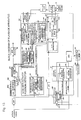
- the first-half part (I) deals with (A) Manufacturing a disk, (B) Forming a marking by using laser light, (C) Reading the position information of the marking, (D) Encrypting the position information, converting the encrypted position information into a barcode, and writing the barcode in a pre-pit area of the optical disk in overwriting fashion, and (E) Playing back the optical disk on a player.
- the second-half part (II) first describes (A) Usefulness of the barcode for a laminated-type optical disk, then proceeds to (B) Barcoding the position information of the marking as a disk-unique ID, (C) Features of the barcode-recorded optical disk format, methods of tracking control, and methods of rotational speed control during reading of the barcode, and (D) Playing back the barcode-recorded optical disk.
- the second-half part (II) further deals in detail with (E) Manufacturing techniques for implementing the barcode recording method, followed by a brief explanation of a barcode playback apparatus (player). Finally, a description is given of (F) An example of the above barcode encryption and another application example of the barcode.
- laser trimming is also referred to as laser marking
- a nonreflective optical marking portion is simply referred to as the barcode, stripe, marking, or optical marking or, sometimes, as the physical ID unique to a disk.
- the software company performs software authoring in software production process 820.
- the completed software is delivered from the software company to the disk manufacturing factory.
- disk manufacturing process 816 at the disk manufacturing factory the completed software is input in step 818a, a master disk is produced (step 818b), disks are pressed (steps 818e, 818g), reflective films are formed on the respective disks (steps 818f, 818h), the two disks are laminated together (step 818i), and a ROM disk such as a DVD or CD is completed (step 818m, etc.).
- the thus completed disk 800 is delivered to the software maker or to a factory under control of the software maker, where, in secondary recording process 817, an anti-piracy marking 584, such the one shown in Figure 2, is formed (step 819a), and accurate position information of this mark is read by a measuring means (step 819b) to obtain the position information which serves as the physical feature information of the disk.
- This physical feature information of the disk is encrypted in step 819c.
- the encrypted information is converted to a PE-RZ-modulated signal which is then recorded in step 819d as a barcode signal on the disk by using a laser.
- the disk physical feature information may be combined together with software feature information for encryption in step 819c.
Description
- The present invention relates to an optical disk having a barcode-like mark according to the preamble part of
claim 1. - An optical disk of this kind is known from EP-A- 741382.
- In the manufacturing process of optical disks, it has been commonly practiced to record a serial number, lot number, etc. on each optical disk in the form of a barcode.
- Since such information cannot be written to a pit information area of the optical disk, it has been practiced to write the barcoded information to a non-information area, or unused space, on the optical disk.
- When reproducing (playing back) such an optical disk, the pit information is read by an optical pickup; to read the barcoded information such as a serial number, etc. recorded in the non-information area, however, a separate reading device has been used.
- In the above prior art optical disk, since information carrying a serial number and the like is not recorded in a pit area but recorded in a non-information area, as described above, a separate reading device has had to be provided in addition to the usual optical pickup, the resulting problem being increases complexity of the playback apparatus construction.
- In view of the above problem with the prior art, it is the object of the present invention to provide an optical disk wherein data such as a disk ID number, etc. is converted into a barcode and recorded on the disk, in fashion permitting the use of a single optical pickup to read both the bit data and barcode data.
- The invention is an optical disk as set forth in
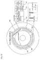
claim 1. Preferred embodiments of the invention are subject matter of the dependent claims. - Figure 1 is a diagram showing a disk manufacturing process and a secondary recording process;
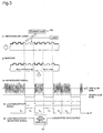
- Figure 2(a) is a top plan view of a disk according to the embodiment, (b) is a top plan view of the disk according to the embodiment, (c) is a top plan view of the disk according to the embodiment, (d) is a transverse sectional view of the disk according to the embodiment, and (e) is a waveform diagram of a reproduced signal according to the embodiment;
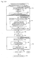
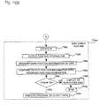
- Figure 3 is a flowchart illustrating a process of recording encrypted position information on a disk in the form of a barcode according to the present embodiment;
- Figure 4 is a diagram showing a disk fabrication process and a secondary recording process (part 1);
- Figure 5 is a diagram showing the disk fabrication process and the secondary recording process (part 2);
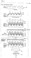
- Figure 6 is a diagram showing a two-layer disk fabrication process (part 1);
- Figure 7 is a diagram showing the two-layer disk fabrication process (part 2);
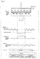
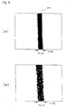
- Figure 8(a) is an enlarged view of a nonreflective portion of a laminated type, and (b) is an enlarged view of a nonreflective portion of a single-plate type;
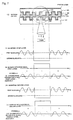
- Figure 9(a) is a reproduced-waveform diagram for a nonreflective portion, (b) is a reproduced-waveform diagram for a nonreflective portion, (c) is a reproduced-waveform diagram for a nonreflective portion, and (d) is a plan view of a master disk produced by a master disk method;
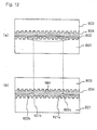
- Figure 10(a) is a cross-sectional view of a nonreflective portion of the laminated type, and (b) is a cross-sectional view of a nonreflective portion of the single-plate;
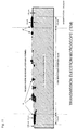
- Figure 11 is a schematic diagram, based on an observation through a transmission electron microscope, illustrating a cross section of the nonreflective portion;
- Figure 12(a) is a cross-sectional view of a disk according to the present embodiment, and (b) is a crosssectional view of the nonreflective portion of the disk according to the present embodiment;
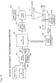
- Figure 13 is a block diagram of a low-reflectivity position detector according to the embodiment;
- Figure 14 is a diagram illustrating the principle of detecting address/clock positions of a low-reflectivity portion according to the embodiment;
- Figure 15A is a flowchart illustrating a procedure for encryption, etc. using an RSA function;
- Figure 15B is a flowchart illustrating a position information check process;
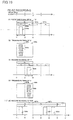
- Figure 16 is a block diagram of a stripe recording apparatus;
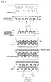
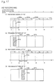
- Figure 17 is a diagram showing a signal waveform and a trimming pattern in RZ recording;
- Figure 18 is a diagram showing a signal waveform and a trimming pattern in NRZ recording;
- Figure 19 is a diagram showing a signal waveform and a trimming pattern in PE-RZ recording;
- Figure 20 is a diagram showing a top plan view of disk stripes, along with signal waveforms;
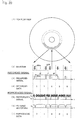
- Figure 21(a) is a perspective view of a converging unit, and (b) is a diagram showing a stripe arrangement and an emitting-pulse signal; and
- Figure 22 is a diagram showing the arrangement of stripes on a disk and the contents of control data.
-
- The preferred embodiments of the present invention will be described below with reference to the accompanying drawings. In the description hereinafter given, position information for piracy prevention, which is a form of ID, is taken as an example of information to be barcoded.
- In the first-half part (I) of the description, a detailed explanation will be given of the piracy prevention position information as a form of ID, followed by a brief explanation of how the information is converted into a barcode to complete an optical disk and how the optical disk is played back. In the second-half part (II), the technique for barcoding the piracy prevention position information will be described in further detail and in a concrete manner. More specifically, the first-half part (I) deals with (A) Manufacturing a disk, (B) Forming a marking by using laser light, (C) Reading the position information of the marking, (D) Encrypting the position information, converting the encrypted position information into a barcode, and writing the barcode in a pre-pit area of the optical disk in overwriting fashion, and (E) Playing back the optical disk on a player. The second-half part (II) first describes (A) Usefulness of the barcode for a laminated-type optical disk, then proceeds to (B) Barcoding the position information of the marking as a disk-unique ID, (C) Features of the barcode-recorded optical disk format, methods of tracking control, and methods of rotational speed control during reading of the barcode, and (D) Playing back the barcode-recorded optical disk. The second-half part (II) further deals in detail with (E) Manufacturing techniques for implementing the barcode recording method, followed by a brief explanation of a barcode playback apparatus (player). Finally, a description is given of (F) An example of the above barcode encryption and another application example of the barcode.
- Before proceeding to the description of the above (A) to (E), we will first describe a general process flow from disk manufacturing to the completion of an optical disk by using the flowchart of Figure 1.
- In this patent specification, laser trimming is also referred to as laser marking, while a nonreflective optical marking portion is simply referred to as the barcode, stripe, marking, or optical marking or, sometimes, as the physical ID unique to a disk.
- First, the software company performs software authoring in
software production process 820. The completed software is delivered from the software company to the disk manufacturing factory. Indisk manufacturing process 816 at the disk manufacturing factory, the completed software is input instep 818a, a master disk is produced (step 818b), disks are pressed (steps 818e, 818g), reflective films are formed on the respective disks (steps 818f, 818h), the two disks are laminated together (step 818i), and a ROM disk such as a DVD or CD is completed (step 818m, etc.). - The thus completed
disk 800 is delivered to the software maker or to a factory under control of the software maker, where, insecondary recording process 817, an anti-piracy marking 584, such the one shown in Figure 2, is formed (step 819a), and accurate position information of this mark is read by a measuring means (step 819b) to obtain the position information which serves as the physical feature information of the disk. This physical feature information of the disk is encrypted instep 819c. The encrypted information is converted to a PE-RZ-modulated signal which is then recorded instep 819d as a barcode signal on the disk by using a laser. The disk physical feature information may be combined together with software feature information for encryption instep 819c. - The above processes will be described in further detail. That is, a disk fabrication process, a marking formation process, a marking position reading process, and an encrypted information writing process for an optical disk according to the present invention will be described in detail with reference to Figures 4 and 5 and Figures 8 to 12. A supplementary explanation will also be given dealing with a disk having two reflective layers with reference to Figures 6 and 7. In the following description, the marking formation process and the marking position reading process are collectively called the secondary recording process.
- (A) First, the disk fabrication process will be
described. In the
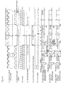
disk fabrication process 806 shown in Figure 4, first atransparent substrate 801 is pressed in step (1). In step (2), a metal such as aluminum or gold is sputtered to form areflective layer 802. Anadhesive layer 804 formed from an ultraviolet curing resin is applied by spin coating to asubstrate 803 formed in a different processing step, and thesubstrate 803 is bonded to thetransparent substrate 801 having thereflective layer 802, and they are rotated at high speed to make the bonding spacing uniform. By exposure to external ultraviolet radiation, the resin hardens, thus firmly bonding the two substrates together. In step (4), a printedlayer 805 where a CD or DVD title is printed, is printed by screen printing or offset printing. Thus, in step (4), the ordinary laminated-type optical ROM disk is completed. - (B) Next, the marking formation process will be
described with reference to Figures 4 and 5. In Figure 4, a
laser beam from a
pulsed laser 813 such as a YAG laser is focused through a converginglens 814 onto thereflective layer 802, to form anonreflective portion 815 as shown in step (6) in Figure 5. That is, a distinct waveform, such as the waveform (A) shown in step (7), is reproduced from thenonreflective portion 815 formed in step (6) in Figure 5. By slicing this waveform, a marking detection signal such as shown by waveform (B) is obtained, from which hierarchial marking position information comprising an address, such as shown in signal (d), and an address, a frame synchronizing signal number, and a reproduced clock count, such as shown in signal (e), can be measured. At the rising edge of the thus obtained marking detection signal, a specific address (indicated by address n in Figure 5(d)) is read by the optical pickup from within the plurality of addresses shown in Figure 5(d). Figure 5(b) shows the physical location of the specific address in schematic form. On the other hand, Figure 5(e) shows the logical structure of the data. As shown in Figure 5(e), there are m frame synchronization signals under address n, and k reproduced clock pulses under each frame synchronization signal. Therefore, the position of the marking measured by the optical pickup can be represented by address, frame synchronization signal number, and reproduced clock count.As previously stated, a supplementary explanation will be given below of an alternative type of disk (a two-layer laminated disk) with reference to Figures 6 and 7.Figures 4 and 5 showed a disk generally known as a single-layer laminated disk which has a reflective layer only on onesubstrate 801. On the other hand, Figures 6 and 7 show a disk generally known as a two-layer laminated disk which has reflective layers on bothsubstrates reflective layer 801 formed on the reading-side substrate 801 is a semi-transparent gold (Au) film having a reflectivity of 30%, while thereflective layer 802 formed on the print-side substrate 803 is the same as that used in the single-layer disk. Second, as compared with the single-layer disk, the two-layer disk is required to have high optical accuracy; for example, theadhesive layer 804 must be optically transparent and be uniform in thickness, and the optical transparency must not be lost due to laser trimming.Parts (7), (8), and (9) of Figure 7 show the signal waveforms obtained from the first layer of the two-recording-layer disk. Likewise, parts (10), (11), and (12) of Figure 7 show the signal waveforms obtained from the second layer of the two-recording-layer disk. The contents of these signal waveforms are essentially the same as those of the waveforms described with reference to parts (a) to (c) of Figure 5.
The waveform from the second layer is similar to that from the first layer, though the signal level is lower than from the first layer. However, since the first and second layers are bonded together, relative positional accuracy between them is random and can be controlled only with an accuracy of a few hundred microns. As will be described later, since the laser beam passes through the two reflective films, to make an illegal disk the position informations on the first and second layers for the first mark, for example, have to be made to match the same value on the legitimate disk. But making them match would require a near-submicron accuracy in laminating, and consequently, making illegal disks of the two-layer type is practically impossible.The technique for forming the nonreflective optical marking portion will be described in further detail in sections (a) to (d) below with reference to Figures 8 to 12, etc., dealing with the laminated type in comparison with a single-plate type. Figures 8(a) and (b) are micrographs showing plan views of nonreflective optical marking portions, and Figure 10(a) is a simplified schematic cross-sectional view of a nonreflective portion of the two-layer laminated disk. - (a) Using a 5 µj/pulse YAG laser, a laser beam was
applied to a 500angstrom aluminum layer lying 0.6 mm below
the surface of a 1.2mm thick ROM disk consisting of two
0.6mm thick disks laminated together, and, as a result, a 12
µm wide slit-like
nonreflective portion 815 was formed, as shown in theX 750 micrograph of Figure 8(a). In thisX 750 micrograph, no aluminum residues were observed on thenonreflective portion 815. Thick swollen aluminum layers, 2000 angstroms thick and 2 µm wide, were observed along boundaries between thenonreflective portion 815 and reflective portions. As shown in Figure 10(a), it was confirmed that no significant damage had occurred inside. In this case, the application of the pulsed laser presumably melted the aluminum reflective layer, causing a phenomenon of molten aluminum buildup along the boundaries on both sides due to the surface tension. We call this a hot melt surface tension (HMST) recording method. This is a characteristic phenomenon observed only on alaminated disk 800. Figure 11 is a schematic diagram, based on an observation through a transmission electron microscope (TEM), illustrating a cross section of the nonreflective portion formed by the above laser trimming process. And Figure 11 shows that the adhesive layer of the disk has been removed by using solvent. In the figure, if the aluminum film swollen portion is 1.3 µm wide and 0.20 µm thick, the amount of increased aluminum in that portion is 1.3 x (0.20 - 0.05) = 0.195 µm2. The amount of aluminum originally deposited in a half portion (5 µm) of the laser exposed region (10 µm) was 5 x 0.05 = 0.250 µm2. The difference is calculated as 0.250 - 0.195 = 0.055 µm2. In terms of length, this is equivalent to 0. 055/0.05 = 1.1 µm. This means that an aluminum layer of 0.05 µm thickness and 1.1 µm length remained, and therefore, it can be safely said that almost all aluminum was drawn to the film swollen portion. Thus, the result of the analysis of the figure also verifies the explanation about the above-described characteristic phenomenon. - (b) We will next deal with the case of a single-plate
optical disk (an optical disk comprising a single disk).
An experiment was conducted by applying laser pulses of the
same power to a 0.05 µm thick aluminum reflective film
formed on a single-sided molded disk, of which result is shown
in Figure 8(b). As shown in the figure, aluminum residues
were observed, and since these aluminum residues cause
reproduction noise, it can be seen that the single-plate
type is not suitable for secondary recording of optical disk
information of which a high density and a low error rate
are demanded. Furthermore, unlike the laminated disk, in the
case of the single-plate disk, the
protective layer 862 is inevitably damaged, as shown in Figure 10(b), when the nonreflective portion is subjected to laser trimming. The degree of damage depends on the laser power, but the damage cannot be avoided even if the laser power is controlled accurately. Moreover, according to our experiment, the printedlayer 805 formed by screen printing to a thickness of a few hundred microns on theprotective layer 862 was damaged when its thermal absorptance was high. In the case of the single-plate disk, to address the problem of protective layer damage, either the protective layer has to be applied once again or the laser cut operation should be performed before depositing the protective layer. In any case, the single-plate type may present a problem in that the laser cut process has to be incorporated in the pressing process. This limits the application of the single-plate disk despite its usefulness. - (c) A comparison between single-plate disk and
laminated disk has been described above, using a two-layer
laminated disk as an example. As is apparent from the above
description, the same effect as obtained with the two-layer
laminated disk can be obtained with the single-layer
laminated disk. Using Figures 12(a), 12(b), etc., a further
description will be given dealing with the single-layer
laminated disk type. As shown in Figure 12(a), the
reflective layer 802 has thetransparent substrate 801 of polycarbonate on one side, and the hardenedadhesive layer 804 and a substrate on the other side, thereflective layer 802 thus being hermetically sealed therebetween. In this condition, pulsed laser light is focused thereon for heating; in the case of our experiment, heat of 5 µJ/pulse is applied to a circular spot of 10 to 20 µm diameter on thereflective layer 802 for a short period of 70 ns. As a result, the temperature instantly rises to 600°C, the melting point, melting state is caused. By heat transfer, a small portion of thetransparent substrate 801 near the spot is melted, and also a portion of theadhesive layer 804 is melted. The molted aluminum in this state is caused by surface tension to build up alongboundaries 821a and 821b, with tension being applied to both sides, thus formingbuildups nonreflective portion 584 free from aluminum residues is thus formed. This shows that a clearly definednonreflective portion 584 can be obtained by laser-trimming the laminated disk as shown in Figures 10(a) and 12(a). Exposure of the reflective layer to the outside environment due to a damaged protective layer, which was the case with the single-plate type, was not observed even when the laser power was increased more than 10 times the optimum value. After the laser trimming, thenonreflective layer 584 has the structure shown in Figure 12(b) where it is sandwiched between the twotransparent substrates adhesive layer 804 against the outside environment, thus producing the effect of protecting the structure from environmental effects. - (C) Next, the process of reading the position of the
thus formed marking will be described.
Figure 13 is a block diagram showing a low reflectivity
light amount detector 586 for detecting the nonreflective optical marking portion, along with its adjacent circuitry, in an optical disk manufacturing process. Figure 14 is a diagram illustrating the principle of detecting address/clock positions of the low reflectivity portion. For convenience of explanation, the following description deals with the operating principle when a read operation is performed on a nonreflective portion formed on an optical disk constructed from a single disk. It will be recognized that the same operating principle also applies to an optical disk constructed from two disks laminated together.As shown in Figure 13, thedisk 800 is loaded into a marking reading apparatus equipped with a lowreflectivity position detector 600 to read the marking, and in this case, since asignal waveform 823 due to the presence and absence of pits and asignal waveform 824 due to the presence of thenonreflective portion 584 are significantly different in signal level, as shown in the waveform diagram of Figure 9(a), they can be clearly distinguished using a simple circuit.Figure 9(a) is a diagram showing the waveform of a playback signal from a PCA area, described later, containing thenonreflective portion 584 formed by laser light. Figure 9(b) is a diagram showing the waveform of Figure 9(a) but with a different time axis.By removing the reflective film by laser light, as described above, a waveform easily distinguishable from that of a pit signal is obtained. Rather than forming an anti-piracy identification mark by removing the reflective film by laser light, as described above, the anti-piracy mark may be formed by changing the shape of pits on the master disk. This method will be described below. Figure 9(c) shows the waveform of a playback signal when the anti-piracy identification mark was formed by making pits longer than other data pits on the master disk. It can be seen from the diagram that thewaveform 824p of the anti-piracy identification mark is distinguishable from the waveform of other pit data. In this way, a waveform similar to that obtained from the PCA area described later can be obtained by forming longer pits on the master disk; in this case, however, the waveform is a little difficult to distinguish as compared to the waveforms shown in parts (a) and (b) of Figure 9.By removing the reflective film by laser light, as described above, a waveform easily distinguishable from that of a pit signal is obtained. Rather than forming the barcode of the invention by removing the reflective film by laser light, as described above, the barcode may be formed by changing the shape of pits on the master disk. This master disk method will be described below. Figure 9(d) is a plan view showing a portion of a master disk whereinpits 824q in a few hundred tracks on the master disk are made longer than other data pits and made equal to the barcode bar width t (= 10 µm). Since reflectivity drops in this longer-bit area, awaveform 824 p as shown in Figure 9(c) is obtained. It can be seen from the diagram that thewaveform 824p by the master disk method is distinguishable from the waveform of other pit data. In this way, a waveform similar to that obtained from the PCA area described later can be obtained by the master disk method; in this case, however, the waveform is a little difficult to distinguish as compared to the waveforms shown in parts (a) and (b) of Figure 9.As shown in Figure 14(1), the start and end positions of the nonreflective portion 564 having the above waveform can be easily detected by the low reflectivitylight amount detector 586 shown in the block diagram of Figure 13. Using the reproduced clock signal as the reference signal, position information is obtained in a low reflectivity positioninformation output section 596. Figure 14(1) shows a cross-sectional view of the optical disk.As shown in Figure 13, acomparator 587 in the low reflectivitylight amount detector 586 detects the low reflectivity light portion by detecting an analog light reproduced signal having a lower signal level than a lightamount reference value 588. During the detection period, a low reflectivity portion detection signal of the waveform shown in Figure 14(5) is output. The addresses and clock positions of the start position and end position of this signal are measured.The reproduced light signal is waveshaped by awaveform shaping circuit 590 having anAGC 590a, for conversion into a digital signal. Aclock regenerator 38a regenerates a clock signal from the waveshaped signal. AnEFM demodulator 592 in ademodulating section 591 demodulates the signal, and an ECC corrects errors and outputs a digital signal. The EFM-demodulated signal is also fed to a physicaladdress output section 593 where an address of MSF, from Q bits of a subcode in the case of a CD, is output from anaddress output section 594 and a synchronizing signal, such as a frame synchronizing signal, is output from a synchronizingsignal output section 595. From theclock regenerator 38a, a demodulated clock is output.In a low reflectivity portion address/clock signal positionsignal output section 596, a low reflectivity portion start/end position detector 599 accurately measures the start posistion and end position of thelow reflectivity portion 584 by using an (n-1) address output section 597 and an address signal as well as aclock counter 598 and a synchronizing clock signal or the demodulated clock. This method will be described in detail by using the waveform diagrams shown in Figure 16. As shown in the cross-sectional view of the optical disk in Figure 14(1), thelow reflectivity portion 584 ofmark number 1 is formed partially. A reflection slope signal such as shown in Figure 14(3), is output, the signal level from the reflective portion being lower than the lightamount reference value 588. This is detected by thelight level comparator 587, and a low reflectivity light detection signal, such as shown in Figure 14(5), is output from the low reflectivitylight amount detector 586. As shown by a reproduced digital signal in Figure 14(4), no digital signal is output from the mark region since it does not have a reflective layer.Next, to obtain the start and end positions of the low reflectivity light detection signal, the demodulated clock or synchronizing clock shown in Figure 14(6) is used along with address information. First, areference clock 605 at address n in Figure 14(7) is measured. Then the address immediately preceding the address n is detected by the (n-1) address output section 597, it is found that thenext sync 604 is a sync at address n. The number of clocks from thesynch 604 to thereference clock 605, which is the start position of the low reflectivity light detection signal, is counted by theclock counter 598. This clock count is defined as a reference delay time TD which is measured by a reference delay timeTD measuring section 608 for storage therein.The circuit delay time varies with reproduction apparatus used for reading, which means that the reference delay time TD varies depending on the reproduction apparatus used. Therefore, using the TD, a time delay corrector 607 applies time correction, and the resulting effect is that the start clock count for the low reflectivity portion can be measured accurately if reproduction apparatus of different designs are used for reading. Next, by finding the clock count and the start and end addresses for the optical mark No. 1 in the next track, clock m+14 at address n+12 is obtained, as shown in Figure 14(8). Sincemark 1 at address n in Figure 14(8) relative to anothermark 2 matches or not. That is, TD is ignored as a variable, and the difference between the position,mark 1 measured and the position,mark 2 measured is obtained, which is given asmark 1 and the position information a2 of themark 2, thereby judging whether the disk is a legitimate disk or not. The effect of this method is that the positions can be checked after compensating for variations of the reference delay time TD by using a simpler constitution. - (D) Next, the encrypted information writing process
will be described. The position information read in the
process (C) is first converted into ciphertext or "signed"
with a digital signature. Then, the marking position
information thus encrypted or signed is converted into a
barcode as an ID unique to the optical disk, and the barcode
is recorded in overwriting fashion in a prescribed region of
a pre-pit area on the optical disk.
Barcode patterns 584c - 584e in Figure 2(a) indicate the barcode written to the prescribed region of the pre-pit area, that is, in the innermost portion of the pre-pit area. Parts (1) to (5) of Figure 3 show the process from the recording of the barcode to the demodulation of the barcode detection signal by a PE-RZ modulated signal demodulator. In part (1) of Figure 3, the reflective layer is trimmed by a pulsed laser, and a barcode-like trimming pattern, such as shown in part (2) of the figure, is formed. At the playback apparatus (player), an envelope waveform some portions of which are missing, as shown in part (3) of the figure, is obtained. The missing portions result in the generation of a low level signal that cannot occur with a signal generated from an ordinary pit. Therefore, this signal is sliced by a second slice level comparator to obtain a low-reflectivity portion detection signal as shown in part (4) of the figure. In part (5) of the figure, the playback signal of the barcode is demodulated from this low-reflectivity portion detection signal by the PE-RZ modulatedsignal demodulator 621 which will be described in detail in the second-half part (II). It will be appreciated that, instead of the PE-RZ modulatedsignal demodulator 621, a pulse-width modulated signal demodulator (PWM demodulator) may be used, in which case also, a similar effect can be obtained.When applying the above encryption or digital signature, a secret key of a public key encryption function is used. As an example of the encryption, Figures 18A and 18B show an encryption process using an RSA function.As shown in Figure 1 5 A, the process consists of the following major routines:step 735a where marking position information is measured at the optical disk maker, step 695 where the position information is encrypted (or a digital signature is appended),step 698 where the position information is decrypted (or the signature is verified or authenticated) in the reproduction apparatus, andstep 735w where a check is made to determine whether the disk is a legitimate optical disk or not.First, instep 735a, the marking position information on the optical disk is measured instep 735b. The position information is then compressed instep 735d, and the compressed position information H is obtained instep 735e.In step 695, the ciphertext of the compressed position information H is constructed. First, instep 695, a secret key, d, of 512 or 1024 bits, and secret keys, p and q, of 256 or 512 bits, are set, and instep 695b, encryption is performed using an RSA function. When the position information H is denoted by M, M is raised to d-th power and mod n is calculated to yield ciphertext C. Instep 695d, the ciphertext C is recorded on the optical disk. The optical disk is thus completed and is shipped (step 735k).In the reproduction apparatus, the optical disk is loaded instep 735m, and the ciphertext C is decrypted instep 698. More specifically, the ciphertext C is recovered instep 698e, and public keys, e and n, are set in step 698f; then in step b, to decrypt the ciphertext C, the ciphertext C is raised to e-th power and the mod n of the result is calculated to obtain plaintext M. The plaintext M is the compressed position information H. An error check may be performed instep 698g. If no errors, it is decided that no alterations have been made to the position information, and the process proceeds to thedisk check routine 735w shown in Figure 1 5 B. If an error is detected, it is decided that the data is not legitimate one, and the operation is stopped.In thenext step 736a, the compressed position information H is expanded to recover the original position information. Instep 736c, measurements are made to check whether the marking is actually located in the position on the optical disk indicated by the position information. Instep 736d, it is checked whether the difference between the decrypted position information and the actually measured position information falls within a tolerance. If the check is OK instep 736e, the process proceeds to step 736h to output software or data or execute programs stored on the optical disk. If the check result is outside the tolerance, that is, if the two pieces of position information do not agree, a display is produced to the effect that the optical disk is an illegally duplicated one, and the operation is stopped instep 736g. RSA has the effect of reducing required capacity since only the ciphertext need be recorded. - (E)The processing steps in the optical disk manufacturing process have been described above. Next, the constitution and operation of a reproduction apparatus (player) for reproducing the thus completed optical disk on a player will be described. The construction of an optical disk will be described first. A marking is formed on a reflective layer deposited on the optical disk. In the manufacturing process of the optical disk, the position of the marking was detected by position detecting means, and the detected position was encrypted as marking position information and written on the optical disk in the form of a barcode.Position information reading means reads the barcode, and decrypting means contained therein decrypts the contents of the barcode for output. Marking reading means reads the actual position of the marking and outputs the result. Comparing/judging means compares the decrypted result from the decrypting means contained in the position information reading means with the result of reading by the marking reading means, and judges whether the two agree within a predetermined allowable range. If they agree, a reproduction signal for reproducing the optical disk is output; if they do not agree, a reproduction stop signal is output. Control means controls the reproduction operation of the optical disk in accordance with these signals; when the reproduction stop signal is output, an indication to the effect that the optical disk is an illegal duplicated disk is displayed on a display and the reproduction operation is stopped. In the above operation, it will be recognized that it is also possible for the marking reading means to use the decrypted result from the decrypting means when reading the actual position of the marking.Namely in this case, the marking reading means checks whether the marking is actually located in the position on the optical disk indicated by the position information which is decrypted by the decrypting means.Thus the reproduction apparatus of the above construction can detect an illegally duplicated optical disk and stop the reproduction operation of the disk, and can prevent illegal duplicates practically.
-
- We finish here the description of the first-half part (I), and now proceed to the description of the second-half part (II). This part focuses particularly on techniques, including a barcode formation method, used when barcoding the above marking position information (ID information) as a disk-unique ID.
- (A) Features of the optical disk of the present invention
will be described.
Then a barcode is recorded by laser trimming on the
above-described single-plate disk, the
protective layer 862 is destroyed, as explained in connection with Figure 10(b). Therefore, after laser trimming at a press factory, the destroyedprotective layer 862 has to be reformed at the press factory. This means that a barcode cannot be recorded on the optical disk at a software company or a dealer that does not have the necessary equipment. The problem expected here is that the application of barcode recording is greatly limited.On the other hand, when the marking position information was recorded as a barcode by laser trimming on the laminated-type disk of the invention formed from two transparent substrates laminated together, it was confirmed that theprotective layer 804 remained almost unchanged, as already explained in connection with Figure 10(a). This was confirmed by experiment by observing the disk under an optical microscope of 800X magnification. It was also confirmed that no change had occurred to the reflective film in the trimmed portion after an environmental test of 96 hours at a temperature of 85°C and a humidity of 95%.In this way, when the laser trimming of the present invention is applied to a laminated disk such as a DVD, there is no need to reform the protective layer at the factory. This offers a great advantage in that a barcode can be recorded by trimming on the optical disk at a place other than the press factory, for example, at a software company or a dealer. The usefulness of barcode recording on the laminated-type optical disk was thus confirmed.In this case, since the secret key information for encryption that the software company keeps need not be delivered to a party outside the company, security increases greatly, particularly when security information such as a serial number for copy prevention is recorded as a barcode in addition to the above-described position information. Furthermore, in the case of a DVD, since the barcode signal can be separated from DVD pit signals by setting the trimming line width at a value greater than 14T or 1.82 microns, as will be described later, the barcode signal can be recorded in the pit recording area on the DVD in superimposing fashion. The barcode formed in this way offers the effect that the barcode can be read by the optical pickup used to read the pit signal. This effect can be obtained not only with the laminated-type disk but also with the previously described single-plate disk.Thus, by applying the barcode forming method and modulation recording method of the invention to a laminated-type disk such as a DVD, a laminated-type optical disk can be provided that permits secondary recording after shipment from the factory. The above description has dealt mainly with a case in which the barcode is formed by laser trimming on a laminated-type disk of a two-layer, single-sided structure (with two reflective layers formed on one side). This single-sided, two-layered optical disk is the type of disk that permits playback of both sides from one side of the disk without having to turn over the disk.On the other hand, when trimming is performed on a double-sided, laminated-type optical disk that needs turning over when playing back the reverse side, the laser light passes through the two reflective films each formed on one side of the disk. Therefore, the barcode can be formed simultaneously on both sides. This provides an advantage for media fabrication in that the barcode can be recorded simultaneously on both sides in a single step.In this case, when the optical disk is turned over to play back the reverse side on a playback apparatus, the barcode signal is played back in just the opposite direction to the direction that the barcode signal on the front side is played back. A method for identifying the reverse side is therefore needed. This will be described in detail later. - (B) Referring now to Figures 16 to 19, etc., we will
describe the construction and operation of an optical disk
barcode forming apparatus for converting the marking
position information (ID number) into a barcode as a disk-unique
ID and for recording the barcode in a prescribed
region of a pre-pit area. A barcode recording method, etc.
will also be described.
- (a) First, the optical disk barcode recording apparatus
will be described with reference to Figure 16.
Figure 16 is a diagram showing the configuration of the
barcode recording apparatus for implementing an optical disk
barcode forming method in one embodiment of the present
invention. In the above mentioned embodiment, data to be
barcoded is the data of encrypted version of marking position
information. But the data to be barcode is not restricted to
the above embodement. It may include, for example, input data
and an ID number issued from an
ID generator 908, as shown in Figure 16, or any other kind of data.In Figure 16, the input data and the ID number issued from theID generator 908 are combined together in aninput section 909; in anencryption encoder 830, the combined data is subjected to signature or encryption using an RSA function, etc. as necessary, and in anECC encoder 907, error-correction coding and interleaving are applied. The encryption process and the playback process will not be described in detail.The data is then fed into anRZ modulator 910 where phase-encoding (PE) RZ modulation to be described later is performed. The modulating clock used here is created by aclock signal generator 913 in synchronism with a rotation pulse from amotor 915 or a rotation sensor 915a.Based on the RZ-modulated signal, a trigger pulse is created in alaser emitting circuit 911, and is applied to alaser 912 such as a YAG laser established by a laserpower supply circuit 929. Thelaser 912 thus driven emits pulsed laser light which is focused through a convergingunit 914 onto thereflective film 802 on thelaminated disk 800, removing the reflective film in a barcode pattern. The error-correction method will be described in detail later. For encryption, a public key cipher, such as the one shown in Figure 18, is appended as a signature to the serial number with a secret key that the software company has. In this case, since no one other than the software company has the secret key and therefore cannot append a legitimate signature to a new serial number, this has an enormous effect in preventing illegal manufacturers from issuing a serial number. Since the public key cannot be deciphered, as previously described, the security is greatly enhanced. Disk piracy can thus be prevented even when the public key is recorded on the disk for delivery.The convergingunit 914 in the optical disk barcode forming apparatus of the present embodiment will be described below in more detail.As shown in Figure 21(a), light emitted from thelaser 912 enters the convergingunit 914 where the entering light is converted by acollimator 916 into a parallel beam of light which is then converged in only one plane by acylindrical lens 917, thus producing a stripe of light. This light is limited by amask 918, and is focused through a converginglens 919 onto thereflective film 802 on the optical disk to remove the film in a stripe pattern. A stripe such as shown in Figure 28(b) is thus formed. In PE modulation, stripes are spaced apart at three different intervals, 1T, 2T, and 3T. If this spacing is displaced, jitter occurs and the error rate rises. In the present invention, theclock generator 913 generates a modulating clock in synchronism with a rotation pulse from themotor 915, and supplies this modulating clock to themodulator 910 to ensure that eachstripe 923 is recorded at a correct position in accordance with the rotation of themotor 915, that is, with the rotation of thedisk 800. This has the effect of reducing jitter. Alternatively, a laser scanning means 950, such as shown in Figure 3(1), may be provided by which a continuous-wave laser is scanned in a radial direction to form a barcode. - (b) Next, a barcode recording method, etc., for forming
a barcode using the above-described barcode recording
apparatus, will be described with reference to Figure 17 to
19.
Figure 17 shows signals coded with RZ recording
(polarity return-to-zero recording) of the invention and
trimming patterns formed corresponding to them. Figure 18
shows signals coded with a conventional barcode format and
trimming patterns formed corresponding to them.The present invention uses RZ recording, as shown in
Figure 17. In this RZ recording, one unit time is divided
into a plurality of time slots, for example, a
first time slot 920a, a second time slot 921, a third time slot 922, and so on. Then data is "00", for example, asignal 924a of a duration shorter than the period of the time slot, that is, the period T of a channel clock, is recorded in thefirst time slot 920a, as shown in part (1) in Figure 19. Thepulse 924a whose duration is shorter than the period T of the recording clock is output betweenrotation sensor 915a on themotor 915, theclock signal generator 913 generates a modulation clock pulse as shown in part (1) of Figure 17; by performing the recording in synchronism with the clock pulse, the effects of rotational variation of the motor can be eliminated. In this way, as shown in part (2) of Figure 17, astripe 923a indicating "00" is recorded on the disk within arecording region 925a, the first of the four recording regions shown, and a circular barcode such as shown in part (1) of Figure 20 is formed.Next, when data is "01", apulse 924b is recorded in thesecond time slot 921b betweenstripe 923b is recorded on the disk within arecording region 926b, the second region from the left, as shown in part (4) of Figure 17.Next, when recording data "10" and "11", these data are recorded in thethird time slot 922a and fourth time slot, respectively.Here, for comparison purposes, NRZ recording (non-return-to-zero recording) used for conventional barcode recording will be described with reference to Figure 18.In NZR recording,pulses time slot 920a, are output, as shown in part (1) of Figure 18. In RZ recording, the width of each pulse is 1/nT; on the other hand, in the case of NZR recording, a pulse as wide as T is needed, and furthermore, when T appears successively, a pulse of double or triple width, 2T or 3T, becomes necessary, as shown in part (3) of Figure 18. In the case of laser trimming such as described in the present invention, changing the laser trimming width is practically difficult since it necessitates changing settings, and therefore, NRZ is not suitable. As shown in part (2) of Figure 18,stripes third recording regions stripe 929b ofwidth 2T is recorded in the second andthird recording regions period 1T of the clock signal, or 2T or 3T, that is, with nT. It is particularly difficult to record various line widths such as 2T and 3T by varying the line width for each bar (each stripe). Since the conventional product barcode format is an NRZ format, if this format is applied to the laser-recorded barcode of the present invention, the fabrication yield will decrease because it is difficult to precisely record varying line widths such as 2T and 2T on the same disk; furthermore, stable recording cannot be done since the laser trimming width varies. This makes demodulation difficult. Using RZ recording, has the effect of achieving stable digital recording even if the laser trimming width varies. Further, this offers the effect of simplifying the construction of the recording apparatus since RZ recording requires only one kind of line width and the laser power therefore need not be modulated.As described, by employing the above RZ recording for optical disk barcode recording, there is offered the effect of ensuring stable digital recording.An example of the phase-encoding (PE) modulation of RZ recording will be described with reference to Figure 19.Figure 19 shows signals and an arrangement of stripes when the RZ recording shown in Figure 17 is PE-modulated. As shown, data "0" is recorded in the left-hand time slot 920a of the twotime slots hand time slot 921a, as shown in part (3) of Figure 19. On the disk, data "0" is recorded as astripe 923a in the left-hand recording region 925a and data "1" as astripe 923b in the right-hand recording region 926b, as shown in parts (2) and (4) of Figure 19, respectively. Thus, for data "010", apulse 924c is output in the left-hand time slot for "0", apulse 924d is output in the right-hand time slot for "1", and apulse 924e is output in the left-hand time slot for "0", as shown in part (5) of Figure 19; on the disk, the first stripe is formed in the left-hand position, the second stripe in the right-hand position, and the third stripe in the left-hand position, by laser trimming. Figure 19(5) shows signals modulated with data "010". As can be seen, a signal is always available for every channel bit. That is, since the signal density is constant, the DC component does not vary. Since the DC component does not vary, PE modulation is resistant to variation in low-frequency components even if a pulse edge is detected during playback. This has the effect of simplifying playback demodulator circuitry of the disk playback apparatus. Furthermore, since onesignal 923 is always available for everychannel clock 2T, this has the effect of being able to reproduce a synchronization clock for a channel clock without using a PLL.A circular barcode, such as shown in Figure 20(1), is thus formed on the disk. Then data "01000", shown in part Figure 20(4), is recorded, in the PE-RZ modulation of the invention abarcode 923a having the same pattern as the recorded signal shown in part (3) is recorded as shown in part (2). Then this barcode is played back by an optical pickup, a signal waveform, such as shown in part (5) REPRODUCED SIGNAL, is output with portions thereof dropped corresponding to missing portions of a pit-modulated signal where no reflection signals are obtained due to removal of the reflective film, as explained with reference to part Figure 5(6). By passing this reproduced signal through a second-order or third-order LPF filter, the filtered signal waveform shown in Figure 20(6) is obtained. By slicing this signal by a level slicer, reproduced data "01000" of part (7) is demodulated. - (C) We will next describe features of the optical disk
format with a barcode formed in the above manner, tracking
control methods, and rotational speed control methods that
can be used when playing back the optical disk.
- (a) We will first describe the features of the optical
disk format with a barcode formed according to the present
embodiment, while dealing with an example of a condition
that permits tracking control during playback (this
condition is also referred to as the tracking ON condition).
A playback operation using tracking control,
and its details will not be given.
In the case of a DVD disk in the present embodiment,
all data are recorded in pits with CLV, as shown in Figure
30. Stripes 923 (forming a barcode) are recorded with CAV.
CLV recording means recording with constant linear velocity,
while CAV recording means recording with constant angular
velocity.In the present invention, the
stripes 923 are recorded with CAV, superimposed on a pre-pit signal in a lead-in data area holding an address which is recorded with CLV. That is, the data is overwritten with the stripes. In the present invention, the pre-pit signal area maps into all the data areas where pits are formed. The prescribed region of the pre-pit signal area, as mentioned in the present invention, corresponds to an inner portion of the optical disk; this region is also called a post-cutting area (PCA). In this PCA area, the barcode is recorded with CAV, superimposed on pre-bit signals. In this way, the CLV data is recorded with a pit pattern from the master disk, while the CAV data is recorded with laser-removed portions of the reflective film. Since the barcode data is written in overwriting fashion, pits are recorded between thebarcode stripes -
Claims (3)
- An optical disk on which data including control data is recorded and comprising of a location (923) for receiving a barcode-like mark extending in a circumferential direction and having a plurality of bars (923a, 923b...) each extending in a radial direction, characterized in that said optical disk further comprises of an identifier (937) for indicating whether a barcode-like mark is present or not on said location (923) of the disk, said identifier (937) being provided in an area holding control data (936) and that at least a portion of said barcode-like mark overwrites a pre-pit area of said disk.
- An optical disk according to claim 1, wherein one of said bars (923a), when present, has a lower reflectivity than an average reflectivity of an area between said one of said bars (923a) and another of said bars (923b).
- An optical disk according to claim 1, wherein said pre-pit area is a portion of said disk at which pits are recorded.
Applications Claiming Priority (5)
| Application Number | Priority Date | Filing Date | Title |
|---|---|---|---|
| JP26124795 | 1995-10-09 | ||
| JP26124795 | 1995-10-09 | ||
| JP891096 | 1996-01-23 | ||
| JP891096 | 1996-01-23 | ||
| EP96915172A EP0807929B1 (en) | 1995-10-09 | 1996-05-15 | Optical disk provided with bar code |
Related Parent Applications (1)
| Application Number | Title | Priority Date | Filing Date |
|---|---|---|---|
| EP96915172A Division EP0807929B1 (en) | 1995-10-09 | 1996-05-15 | Optical disk provided with bar code |
Publications (2)
| Publication Number | Publication Date |
|---|---|
| EP1005034A1 EP1005034A1 (en) | 2000-05-31 |
| EP1005034B1 true EP1005034B1 (en) | 2000-11-02 |
Family
ID=26343534
Family Applications (15)
| Application Number | Title | Priority Date | Filing Date |
|---|---|---|---|
| EP00109899A Expired - Lifetime EP1028423B1 (en) | 1995-10-09 | 1996-05-15 | An optical barcode forming method for optical discs, a marking forming apparatus, and a method of manufacturing an optical disk |
| EP04006711A Expired - Lifetime EP1465164B1 (en) | 1995-10-09 | 1996-05-15 | Reproduction circuit in an optical disk reproduction apparatus |
| EP00110461A Expired - Lifetime EP1030297B1 (en) | 1995-10-09 | 1996-05-15 | An optical disk and an optical disk recording method |
| EP00106447A Expired - Lifetime EP1006517B1 (en) | 1995-10-09 | 1996-05-15 | An optical disk and an optical disk reproduction apparatus |
| EP00105014A Expired - Lifetime EP1006516B1 (en) | 1995-10-09 | 1996-05-15 | An optical disk and an optical disk reproduction apparatus |
| EP00101774A Expired - Lifetime EP1005033B1 (en) | 1995-10-09 | 1996-05-15 | An optical disk and an optical disk reproduction apparatus |
| EP02015194A Expired - Lifetime EP1251501B1 (en) | 1995-10-09 | 1996-05-15 | An optical disk with an optical barcode and reproduction apparatus |
| EP06002367A Expired - Lifetime EP1659580B1 (en) | 1995-10-09 | 1996-05-15 | Bar code information method for optical disc |
| EP96915172A Expired - Lifetime EP0807929B1 (en) | 1995-10-09 | 1996-05-15 | Optical disk provided with bar code |
| EP02015195A Expired - Lifetime EP1251502B1 (en) | 1995-10-09 | 1996-05-15 | An optical disk with an optical barcode |
| EP00104818A Expired - Lifetime EP1005035B1 (en) | 1995-10-09 | 1996-05-15 | An optical disk and an optical disk reproduction apparatus |
| EP00112310A Expired - Lifetime EP1031974B1 (en) | 1995-10-09 | 1996-05-15 | An optical disk reproduction apparatus |
| EP00103257A Expired - Lifetime EP1003162B1 (en) | 1995-10-09 | 1996-05-15 | An optical disk and an optical disk reproduction apparatus |
| EP00109898A Expired - Lifetime EP1028422B1 (en) | 1995-10-09 | 1996-05-15 | An optical disk, an optical disk reproduction apparatus |
| EP00101775A Expired - Lifetime EP1005034B1 (en) | 1995-10-09 | 1996-05-15 | An optical disk carrying barcoded information |
Family Applications Before (14)
| Application Number | Title | Priority Date | Filing Date |
|---|---|---|---|
| EP00109899A Expired - Lifetime EP1028423B1 (en) | 1995-10-09 | 1996-05-15 | An optical barcode forming method for optical discs, a marking forming apparatus, and a method of manufacturing an optical disk |
| EP04006711A Expired - Lifetime EP1465164B1 (en) | 1995-10-09 | 1996-05-15 | Reproduction circuit in an optical disk reproduction apparatus |
| EP00110461A Expired - Lifetime EP1030297B1 (en) | 1995-10-09 | 1996-05-15 | An optical disk and an optical disk recording method |
| EP00106447A Expired - Lifetime EP1006517B1 (en) | 1995-10-09 | 1996-05-15 | An optical disk and an optical disk reproduction apparatus |
| EP00105014A Expired - Lifetime EP1006516B1 (en) | 1995-10-09 | 1996-05-15 | An optical disk and an optical disk reproduction apparatus |
| EP00101774A Expired - Lifetime EP1005033B1 (en) | 1995-10-09 | 1996-05-15 | An optical disk and an optical disk reproduction apparatus |
| EP02015194A Expired - Lifetime EP1251501B1 (en) | 1995-10-09 | 1996-05-15 | An optical disk with an optical barcode and reproduction apparatus |
| EP06002367A Expired - Lifetime EP1659580B1 (en) | 1995-10-09 | 1996-05-15 | Bar code information method for optical disc |
| EP96915172A Expired - Lifetime EP0807929B1 (en) | 1995-10-09 | 1996-05-15 | Optical disk provided with bar code |
| EP02015195A Expired - Lifetime EP1251502B1 (en) | 1995-10-09 | 1996-05-15 | An optical disk with an optical barcode |
| EP00104818A Expired - Lifetime EP1005035B1 (en) | 1995-10-09 | 1996-05-15 | An optical disk and an optical disk reproduction apparatus |
| EP00112310A Expired - Lifetime EP1031974B1 (en) | 1995-10-09 | 1996-05-15 | An optical disk reproduction apparatus |
| EP00103257A Expired - Lifetime EP1003162B1 (en) | 1995-10-09 | 1996-05-15 | An optical disk and an optical disk reproduction apparatus |
| EP00109898A Expired - Lifetime EP1028422B1 (en) | 1995-10-09 | 1996-05-15 | An optical disk, an optical disk reproduction apparatus |
Country Status (11)
| Country | Link |
|---|---|
| US (30) | US6052465A (en) |
| EP (15) | EP1028423B1 (en) |
| JP (7) | JP3959114B2 (en) |
| KR (2) | KR100354674B1 (en) |
| CN (4) | CN100342443C (en) |
| DE (14) | DE69633353T2 (en) |
| HK (3) | HK1025179A1 (en) |
| MX (1) | MX9704096A (en) |
| MY (1) | MY117673A (en) |
| SG (3) | SG92635A1 (en) |
| WO (1) | WO1997014146A1 (en) |
Cited By (1)
| Publication number | Priority date | Publication date | Assignee | Title |
|---|---|---|---|---|
| US8611727B2 (en) | 2003-12-24 | 2013-12-17 | Home Box Office, Inc. | Personalization of mass-duplicated media |
Families Citing this family (231)
| Publication number | Priority date | Publication date | Assignee | Title |
|---|---|---|---|---|
| EP1028423B1 (en) * | 1995-10-09 | 2004-03-17 | Matsushita Electric Industrial Co., Ltd. | An optical barcode forming method for optical discs, a marking forming apparatus, and a method of manufacturing an optical disk |
| US7191154B2 (en) * | 1995-10-09 | 2007-03-13 | Matsushita Electric Industrial Co., Ltd. | Apparatus for encrypting and recording received content information on a recording medium using both medium identification information and a cipher key for encryption |
| JP4075078B2 (en) * | 1995-10-09 | 2008-04-16 | 松下電器産業株式会社 | optical disk |
| US6408285B1 (en) | 1995-10-09 | 2002-06-18 | Matsushita Electric Industrial Co., Ltd. | Optical disk reading device using both a decipher key and disk identification information for decryption |
| JPH10106146A (en) * | 1996-09-25 | 1998-04-24 | Victor Co Of Japan Ltd | Recording and reproducing method of disk and reproducing device |
| EP1445770B1 (en) * | 1996-12-19 | 2010-02-24 | Panasonic Corporation | Method for recording write-once information on an optical disk. |
| JP3111923B2 (en) * | 1997-04-10 | 2000-11-27 | 松下電器産業株式会社 | Method and apparatus for recording information on optical disc |
| EP0878796B1 (en) * | 1997-05-13 | 2006-04-19 | Kabushiki Kaisha Toshiba | Information recording apparatus, information reproducing apparatus, and information distribution system |
| US6060773A (en) * | 1997-05-15 | 2000-05-09 | Nippon Telegraph And Telephone Corporation | Semiconductor chip and method of manufacturing the same |
| WO1999013470A1 (en) * | 1997-09-11 | 1999-03-18 | Digipress | Optical disc comprising a marking in particular anti-chipping, and method for making same |
| NL1007123C2 (en) * | 1997-09-26 | 1999-03-29 | Od & Me Bv | Record carriers, method for checking such record carriers, methods for manufacturing such record carriers, and apparatus suitable for carrying out such methods. |
| KR100279522B1 (en) * | 1997-11-20 | 2001-03-02 | 니시무로 타이죠 | Copy protection device and information recording medium used in such a copy protection device |
| TW408290B (en) * | 1997-12-29 | 2000-10-11 | Samsung Electronics Co Ltd | Method and apparatus for protecting copyright of digital recording medium and copyright protected digital recording medium |
| US6687826B1 (en) * | 1997-12-29 | 2004-02-03 | Sony Corporation | Optical disc and method of recording data into same |
| JP3818474B2 (en) * | 1998-03-10 | 2006-09-06 | 日本ビクター株式会社 | Disc-shaped recording medium playback device |
| US6736475B2 (en) * | 2000-03-21 | 2004-05-18 | Elesys, Inc. | Method for providing angular position information for a radial printing system |
| US7497534B2 (en) * | 2000-03-21 | 2009-03-03 | Elesys, Inc. | Enhancing angular position information for a radial printing system |
| IL124571A0 (en) | 1998-05-21 | 1998-12-06 | Miki Mullor | Method of restricting software operation within a licensed limitation |
| US7304937B1 (en) | 1998-06-16 | 2007-12-04 | Thomson Licensing | Identification of program information on a recording medium |
| WO2000005716A1 (en) * | 1998-07-22 | 2000-02-03 | Matsushita Electric Industrial Co., Ltd. | Digital data recording device and method for protecting copyright and easily reproducing encrypted digital data and computer readable recording medium recording program |
| JP3716902B2 (en) * | 1998-09-04 | 2005-11-16 | 株式会社ソニー・コンピュータエンタテインメント | Data transmission / reception system, data reception device, data transmission / reception method, data reception method, and recording medium |
| EP1536422B1 (en) * | 1998-09-22 | 2011-11-09 | Panasonic Corporation | Optical disc and method for recording additional information to an optical disc |
| AU6125299A (en) | 1998-10-21 | 2000-05-08 | Matsushita Electric Industrial Co., Ltd. | Optical information recording medium, and method and apparatus for recording andreproduction |
| CN100425284C (en) * | 1999-01-14 | 2008-10-15 | 安米林药品公司 | Methods for glucagon suppression |
| JP4524920B2 (en) * | 1999-02-08 | 2010-08-18 | ソニー株式会社 | Information recording apparatus, information reproducing apparatus, authentication processing apparatus, information recording method, information reproducing method, and authentication processing method |
| EP1058254B1 (en) * | 1999-04-28 | 2004-07-07 | Matsushita Electric Industrial Co., Ltd. | Optical disk, optical disk recording and reproducing apparatus, and method for recording and reproducing |
| EP1054395B1 (en) * | 1999-05-17 | 2007-06-27 | Sony Corporation | Optical disc recording apparatus, optical disc recording methods, and optical discs |
| US6538961B2 (en) | 1999-05-18 | 2003-03-25 | Sony Corporation | Apparatus and method for recording an optical disc identification code |
| SG103842A1 (en) * | 1999-05-21 | 2004-05-26 | Matsushita Electric Ind Co Ltd | Optical disk, and recording/reproducing apparatus and recording method for optical disk |
| US6597654B2 (en) | 1999-05-21 | 2003-07-22 | Matsushita Electric Industrial Co., Ltd. | Recordable optical disk |
| US7079712B1 (en) | 1999-05-25 | 2006-07-18 | Silverbrook Research Pty Ltd | Method and system for providing information in a document |
| US6990055B1 (en) * | 1999-06-22 | 2006-01-24 | Matsushita Electric Industrial Co., Ltd. | Optical disc drive for controlling reproduction of an optical disc having a plurality of data layers |
| US6580683B1 (en) * | 1999-06-23 | 2003-06-17 | Dataplay, Inc. | Optical recording medium having a master data area and a writeable data area |
| US6519213B1 (en) * | 1999-06-29 | 2003-02-11 | Oak Technology, Inc. | Method and apparatus for reading data from a disk |
| JP3292298B2 (en) * | 1999-07-14 | 2002-06-17 | ソニー株式会社 | Information recording apparatus, information recording method, information recording medium, information reproducing apparatus, and information reproducing method |
| WO2001006502A1 (en) * | 1999-07-15 | 2001-01-25 | Matsushita Electric Industrial Co., Ltd. | Optical recording medium and method for recording optical recording medium |
| CN1156846C (en) * | 1999-08-25 | 2004-07-07 | 索尼公司 | Data recorded medium, data reproducing method and reproducing apparatus, and data processing system |
| US7028011B1 (en) * | 1999-09-10 | 2006-04-11 | Eastman Kodak Company | Hybrid optical recording disc with copy protection |
| US6631359B1 (en) * | 1999-09-10 | 2003-10-07 | Dphi Acquisitions, Inc. | Writeable medium access control using a medium writeable area |
| US6661768B1 (en) * | 1999-10-13 | 2003-12-09 | Matsushita Electric Industrial Co., Ltd. | Optical disk, and method and apparatus for reproducing information recorded in optical disk |
| TW561471B (en) * | 2000-01-07 | 2003-11-11 | Matsushita Electric Ind Co Ltd | Information recording disc and information reproducing system |
| KR100762559B1 (en) * | 2000-01-31 | 2007-10-01 | 엘지전자 주식회사 | Method and Apparatus for reproducing recording medium which comprised copyright |
| JP2001268510A (en) * | 2000-03-15 | 2001-09-28 | Sony Corp | Device and method for reproducing information and recording medium |
| US6754143B2 (en) * | 2000-03-24 | 2004-06-22 | Matsushita Electric Industrial Co., Ltd. | Optical information recording medium, and method and apparatus for recording/reproducing information thereon |
| US6532201B1 (en) * | 2000-04-03 | 2003-03-11 | Hewlett-Packard Company | Copy protection for optical discs |
| JP4310885B2 (en) * | 2000-05-11 | 2009-08-12 | ソニー株式会社 | Optical disc apparatus, optical disc access method, and optical disc |
| CN1252580C (en) * | 2000-05-19 | 2006-04-19 | 松下电器产业株式会社 | Data recording medium and reproducing apparatus thereof |
| JP4395998B2 (en) * | 2000-06-07 | 2010-01-13 | ソニー株式会社 | Optical disc apparatus, optical disc recording method, and optical disc |
| WO2002002301A1 (en) | 2000-06-30 | 2002-01-10 | Verification Technologies Inc. | Copy-protected optical media and method of manufacture thereof |
| US7124944B2 (en) * | 2000-06-30 | 2006-10-24 | Verification Technologies, Inc. | Product packaging including digital data |
| US20050063256A1 (en) * | 2000-06-30 | 2005-03-24 | Selinfreund Richard H. | Data storage in optical discs |
| US6638593B2 (en) | 2000-06-30 | 2003-10-28 | Verification Technologies, Inc. | Copy-protected optical media and method of manufacture thereof |
| US7660415B2 (en) * | 2000-08-03 | 2010-02-09 | Selinfreund Richard H | Method and apparatus for controlling access to storage media |
| JP4595182B2 (en) * | 2000-09-07 | 2010-12-08 | ソニー株式会社 | Information recording apparatus, information reproducing apparatus, information recording method, information reproducing method, information recording medium, and program providing medium |
| JP4348851B2 (en) | 2000-09-21 | 2009-10-21 | ソニー株式会社 | Recording medium, disk recording apparatus and method, and disk reproducing apparatus and method |
| EP1577885A3 (en) * | 2000-09-22 | 2007-12-12 | Matsushita Electric Industrial Co., Ltd. | Optical disc and a reproduction method, reproduction apparatus, and recording apparatus for the same |
| US7324647B1 (en) | 2000-10-23 | 2008-01-29 | Bbn Technologies Corp. | Quantum cryptographic key distribution networks with untrusted switches |
| US6769060B1 (en) * | 2000-10-25 | 2004-07-27 | Ericsson Inc. | Method of bilateral identity authentication |
| AU2002214264A1 (en) * | 2000-11-06 | 2002-05-15 | Matsushita Electric Industrial Co., Ltd. | Optical recording medium, optical recording medium production method, optical recording medium production apparatus, program, and medium |
| JPWO2002039434A1 (en) * | 2000-11-07 | 2004-03-18 | 松下電器産業株式会社 | Optical disk, optical disk recording device, optical disk reproduction device, optical disk reproduction method, and optical disk production method |
| US6925048B2 (en) * | 2000-11-16 | 2005-08-02 | Matsushita Electric Industrial Co., Ltd. | Optical disc apparatus |
| JP2002163857A (en) * | 2000-11-22 | 2002-06-07 | Sharp Corp | Method of recording/reproducing information, information recording medium, information recording/ reproducing apparatus, and method for manufacturing information recording medium |
| WO2002082429A2 (en) * | 2000-12-14 | 2002-10-17 | Ecd Systems, Inc. | Systems and methods for optical media modification |
| KR20020079839A (en) * | 2000-12-19 | 2002-10-19 | 소니 가부시끼 가이샤 | Optical disc, recording apparatus and method for optical disc, and its reproducing method |
| JP3847557B2 (en) * | 2000-12-22 | 2006-11-22 | シャープ株式会社 | Playback device |
| US6908725B2 (en) * | 2001-01-16 | 2005-06-21 | Dphi Acquisitions, Inc. | Double-sided hybrid optical disk with surface topology |
| US7368222B2 (en) * | 2001-01-16 | 2008-05-06 | Dphi Acquisitions, Inc. | Optical data storage media with enhanced contrast |
| JP2002319230A (en) * | 2001-01-25 | 2002-10-31 | Sony Computer Entertainment Inc | Recording medium, information processor, server, and method, program for contents distribution and recording medium thereof |
| US20020141583A1 (en) * | 2001-01-29 | 2002-10-03 | Eastman Kodak Company | Copy protection using a preformed ID and a unique ID on a programmable CD-ROM |
| JP4766502B2 (en) * | 2001-02-05 | 2011-09-07 | 独立行政法人産業技術総合研究所 | Multilayer pinhole disk and manufacturing method thereof |
| KR20020067853A (en) * | 2001-02-19 | 2002-08-24 | 주식회사 마크애니 | Apparatus and Method for controlling the copy and play of a digital audio contents using digital watermarking |
| US6582197B2 (en) | 2001-02-22 | 2003-06-24 | Simon E. Coulson | Method of investment casting with casting identification |
| JP2002313031A (en) * | 2001-04-12 | 2002-10-25 | Nec Corp | Optical disk having identification performance |
| EP1251505A3 (en) | 2001-04-17 | 2010-05-19 | Panasonic Corporation | Device and program for checking optical disks |
| US6966837B1 (en) | 2001-05-10 | 2005-11-22 | Best Robert M | Linked portable and video game systems |
| AU2007202951B2 (en) * | 2001-06-08 | 2010-12-16 | Sony Disc & Digital Solutions, Inc. | Optical disc medium, and data recording method and device |
| BR0205529A (en) * | 2001-06-08 | 2003-07-15 | Sony Disc Technology Inc | Optical disc media, and data recording method and apparatus |
| CA2420221A1 (en) * | 2001-06-29 | 2003-02-20 | Shinichi Kazami | Data recording medium, recording medium recording and/reproducing apparatus, and recording or reproducing method |
| JP2003030856A (en) * | 2001-07-17 | 2003-01-31 | Pioneer Electronic Corp | Optical disk and recording/reproducing device |
| KR100788646B1 (en) * | 2001-08-09 | 2007-12-26 | 삼성전자주식회사 | An optical disk Burst Cutting Area code recording method |
| US7068790B1 (en) | 2001-08-31 | 2006-06-27 | Bbn Technologies Corp. | Systems and methods for path set-up in a quantum key distribution network |
| US7062045B2 (en) * | 2001-09-06 | 2006-06-13 | Clwt, Llc | Media protection system and method |
| US20030046568A1 (en) * | 2001-09-06 | 2003-03-06 | Riddick Christopher J. | Media protection system and method and hardware decryption module used therein |
| JP4880140B2 (en) | 2001-09-07 | 2012-02-22 | 任天堂株式会社 | Optical disc, optical disc playback device and recording device |
| KR20040029957A (en) * | 2001-09-14 | 2004-04-08 | 소니 가부시끼 가이샤 | Recording medium reproduction method and reproduction apparatus and recording medium recording method and recording apparatus |
| JP2003118173A (en) * | 2001-10-10 | 2003-04-23 | Nippon Bunka Seiko Kk | Method for imaging on optical disc by ink jet |
| WO2003038822A1 (en) * | 2001-10-31 | 2003-05-08 | Sony Corporation | Data recording method, recorder, and data reproducing method and device |
| US7139885B2 (en) * | 2001-12-27 | 2006-11-21 | Hitachi, Ltd. | Method and apparatus for managing storage based replication |
| TWI258135B (en) | 2002-01-25 | 2006-07-11 | Sony Corp | Information recording device and method, information reproducing device and method, recording medium, and disc recording medium |
| TWI254292B (en) | 2002-01-25 | 2006-05-01 | Sony Corp | Information recording device and method, information reproducing device and method, recording medium and disc recording medium |
| JP4256100B2 (en) * | 2002-01-31 | 2009-04-22 | 富士通株式会社 | Legitimate media management system |
| US7716485B2 (en) | 2002-02-01 | 2010-05-11 | Sca Ipla Holdings Inc. | Systems and methods for media authentication |
| US20050084645A1 (en) * | 2002-02-07 | 2005-04-21 | Selinfreund Richard H. | Method and system for optical disc copy-protection |
| US6775839B1 (en) * | 2002-03-15 | 2004-08-10 | O'brien Patrick J. | Optical storage device with print layer surface feature |
| US7394738B2 (en) * | 2002-03-20 | 2008-07-01 | Hewlett-Packard Development Company, L.P. | Identifying optical disc properties from information read from label side of optical disc |
| US20040199780A1 (en) * | 2002-03-22 | 2004-10-07 | Heung-Chan Seung | Copy-protected optical recording medium, a method for driving therefor and a method of manufacturing thereof |
| US7016294B2 (en) * | 2002-03-25 | 2006-03-21 | Dphi Acquisitions, Inc. | Inner region identifier for optical disk |
| JP4195573B2 (en) * | 2002-04-03 | 2008-12-10 | Tdk株式会社 | Recording data recording method, recording data reproducing method, recording apparatus, reproducing apparatus, and multilayer optical recording medium |
| JP4132934B2 (en) * | 2002-04-12 | 2008-08-13 | 株式会社ソニー・ディスクアンドデジタルソリューションズ | Read-only optical recording medium and optical recording method |
| US20030193883A1 (en) * | 2002-04-15 | 2003-10-16 | Parks William S. | Methods of detecting counterfeit or authentic optical and/or audio discs |
| US7350081B1 (en) | 2002-04-29 | 2008-03-25 | Best Robert M | Secure execution of downloaded software |
| JP2004030860A (en) | 2002-04-30 | 2004-01-29 | Pioneer Electronic Corp | Recording disk and apparatus and method for reproducing recorded information |
| TWI228249B (en) * | 2002-05-28 | 2005-02-21 | Tech Media Corp U | Optical record medium having a scratching-off layer |
| KR100915875B1 (en) * | 2002-06-05 | 2009-09-07 | 엘지전자 주식회사 | High density read only optical disc, and method for recording and reproducing an encoded data on them |
| JP2004087063A (en) * | 2002-07-02 | 2004-03-18 | Sony Corp | Data recording medium, medium information recording method, medium information recording device, medium information reproducing method, medium information reproducing device, information service method, and information service system |
| EP1380982A1 (en) * | 2002-07-08 | 2004-01-14 | Sicpa Holding S.A. | Method and device for coding articles |
| DE10231687A1 (en) * | 2002-07-10 | 2004-01-22 | Robert Bosch Gmbh | Method and device for notifying the driver of a motor vehicle |
| JP2004047020A (en) * | 2002-07-15 | 2004-02-12 | Fuji Electric Holdings Co Ltd | Magnetic disk medium and fixed magnetic disk device |
| US7457416B1 (en) | 2002-07-17 | 2008-11-25 | Bbn Technologies Corp. | Key distribution center for quantum cryptographic key distribution networks |
| JP2004054978A (en) * | 2002-07-17 | 2004-02-19 | Fuji Electric Holdings Co Ltd | Magnetic recording medium provided with track id information, and magnetic recorder |
| JP4451310B2 (en) * | 2002-08-22 | 2010-04-14 | エルジー エレクトロニクス インコーポレイティド | High density optical disc and recording or reproducing method thereof |
| KR20040024007A (en) * | 2002-09-12 | 2004-03-20 | 엘지전자 주식회사 | High density read only optical disc |
| US20040052203A1 (en) * | 2002-09-13 | 2004-03-18 | Brollier Brian W. | Light enabled RFID in information disks |
| CA2497645A1 (en) * | 2002-09-26 | 2004-04-08 | Verification Technologies, Inc. | Authentication of items using transient optical state change materials |
| US7627126B1 (en) | 2002-10-15 | 2009-12-01 | Bbn Technologies Corp. | Systems and methods for implementing path length control for quantum cryptographic systems |
| US7284126B2 (en) * | 2002-11-12 | 2007-10-16 | Agilent Technologies, Inc. | Device authentication using pre-configured security keys |
| US7460670B1 (en) | 2002-12-20 | 2008-12-02 | Bbn Technologies Corp. | Systems and methods for managing quantum cryptographic networks |
| US7236597B2 (en) | 2002-12-20 | 2007-06-26 | Bbn Technologies Corp. | Key transport in quantum cryptographic networks |
| US7036736B2 (en) | 2003-01-08 | 2006-05-02 | Hoss Sarbaz | Event entry and advertising medium |
| ATE553478T1 (en) | 2003-01-23 | 2012-04-15 | Lg Electronics Inc | RECORDING MEDIUM CONTAINING COPY PROTECTION INFORMATION IN INTERMITTENT OR ALTERNATING WAVED PITS AND APPARATUS AND METHOD FOR PRODUCING, RECORDING AND REPRODUCING THE RECORDING MEDIUM |
| WO2004066287A1 (en) | 2003-01-23 | 2004-08-05 | Lg Electronics Inc. | Recording medium with an optional information and apparatus and methods for forming, recording, reproducing and controlling reproduction of the recording medium |
| KR100952949B1 (en) | 2003-01-24 | 2010-04-15 | 엘지전자 주식회사 | Method for managing a copy protection information of high density optical disc |
| US20060203700A1 (en) * | 2003-02-06 | 2006-09-14 | Verification Technologies, Inc. | Method and system for optical disk copy-protection |
| DK1597727T3 (en) * | 2003-02-20 | 2012-04-16 | Koninkl Philips Electronics Nv | Information carrier comprehensive access information |
| KR100932506B1 (en) | 2003-02-27 | 2009-12-17 | 엘지전자 주식회사 | Regeneration control information management and data reproduction control method of high density optical disc |
| US20040172548A1 (en) * | 2003-03-01 | 2004-09-02 | Anderson Daryl E. | Access permission based on optically readable marking on optical disc label region |
| KR100524952B1 (en) * | 2003-03-07 | 2005-11-01 | 삼성전자주식회사 | Method for protecting data of recordable medium and disk drive using the same |
| US20040182933A1 (en) * | 2003-03-17 | 2004-09-23 | Kai-Yuan Tien | Light source structure without moving parts for a laser barcode scanner |
| US7706535B1 (en) | 2003-03-21 | 2010-04-27 | Bbn Technologies Corp. | Systems and methods for implementing routing protocols and algorithms for quantum cryptographic key transport |
| US7430295B1 (en) | 2003-03-21 | 2008-09-30 | Bbn Technologies Corp. | Simple untrusted network for quantum cryptography |
| JP2004326857A (en) * | 2003-04-22 | 2004-11-18 | Sony Corp | Magneto-optical disk and its recording and reproducing method |
| CN1781151B (en) * | 2003-04-29 | 2010-09-01 | 皇家飞利浦电子股份有限公司 | System for copy protection of an information carrier |
| WO2004109670A1 (en) | 2003-05-30 | 2004-12-16 | Doug Carson & Associates, Inc. | Improved multi-layer optical disc format |
| TW588847U (en) * | 2003-06-19 | 2004-05-21 | Yes Tek Corp | Structure of color digital audio-video disc |
| JP4556395B2 (en) * | 2003-08-28 | 2010-10-06 | ソニー株式会社 | Content identification method and content identification system |
| US7391691B2 (en) | 2003-08-29 | 2008-06-24 | General Electric Company | Method for facilitating copyright protection in digital media and digital media made thereby |
| WO2005029492A1 (en) * | 2003-09-18 | 2005-03-31 | Matsushita Electric Industrial Co., Ltd. | Recording/reproducing device and recording medium |
| JP2005093036A (en) * | 2003-09-19 | 2005-04-07 | Sanyo Electric Co Ltd | Recording medium and recording/reproduction device |
| JP3843975B2 (en) * | 2003-10-01 | 2006-11-08 | ソニー株式会社 | Recording medium management apparatus and recording medium management method |
| US7447317B2 (en) | 2003-10-02 | 2008-11-04 | Fraunhofer-Gesellschaft Zur Foerderung Der Angewandten Forschung E.V | Compatible multi-channel coding/decoding by weighting the downmix channel |
| ATE504058T1 (en) * | 2003-10-08 | 2011-04-15 | Panasonic Corp | METHOD FOR RECORDING IDENTIFICATION INFORMATION, APPARATUS THEREOF AND INFORMATION RECORDING MEDIUM |
| DE10351166A1 (en) * | 2003-11-03 | 2005-06-16 | Stefan Schreiber | Hybrid optical disc with modified CD layer |
| US7058378B2 (en) * | 2003-11-18 | 2006-06-06 | Interdigital Technology Corporation | Method and apparatus for automatic frequency correction of a local oscilator with an error signal derived from an angle value of the conjugate product and sum of block correlator outputs |
| US20050105457A1 (en) * | 2003-11-19 | 2005-05-19 | Cookson Christopher J. | Double-sided optical disc with means for indicating its proper direction of rotation |
| US8611195B2 (en) | 2003-11-21 | 2013-12-17 | Koninklijke Philips N.V. | Detection of data in burst cutting area of optical disk |
| EP1687823B1 (en) | 2003-11-21 | 2018-01-10 | Koninklijke Philips N.V. | Recording and reproducing burst cutting areas |
| US7596069B2 (en) * | 2003-11-25 | 2009-09-29 | Dell Products L.P. | Optical medium aligned information system and method |
| JP2005166096A (en) * | 2003-11-28 | 2005-06-23 | Toshiba Corp | Optical disk, optical disk device, optical disk recording and reproducing method, bca code recording device, and bca code recording method |
| EP1542211A3 (en) * | 2003-12-08 | 2006-08-02 | Matsushita Electric Industrial Co., Ltd. | Optical information recording medium and method of recording bar code-like marks |
| EP1555670A1 (en) * | 2004-01-14 | 2005-07-20 | Sgn | Method of preventing unauthorized duplication of an optical disc by authentification of a physical parameter, manufacturing process of such an optical disc and an optical disc thus obtained |
| JP3954583B2 (en) * | 2004-02-16 | 2007-08-08 | メモリーテック株式会社 | Optical disc, optical disc manufacturing apparatus and optical disc manufacturing method |
| US20050185548A1 (en) * | 2004-02-19 | 2005-08-25 | Weirauch Charles R. | Information access control for optical media |
| US7515716B1 (en) | 2004-02-26 | 2009-04-07 | Bbn Technologies Corp. | Systems and methods for reserving cryptographic key material |
| US7697693B1 (en) | 2004-03-09 | 2010-04-13 | Bbn Technologies Corp. | Quantum cryptography with multi-party randomness |
| US7330326B2 (en) * | 2004-03-09 | 2008-02-12 | Hewlett-Packard Development Company, L.P. | Recordable disk rotational speed error correction circuit |
| KR100745112B1 (en) * | 2004-04-22 | 2007-08-01 | 히다치 막셀 가부시키가이샤 | Optical disk recording method, and optical disk |
| US7289644B2 (en) * | 2004-04-27 | 2007-10-30 | Thomson Licensing | Anti-piracy coding of motion pictures |
| CN1950906A (en) * | 2004-05-06 | 2007-04-18 | 皇家飞利浦电子股份有限公司 | Spiral angle controlled information |
| JP2007538320A (en) * | 2004-05-18 | 2007-12-27 | シルバーブルック リサーチ ピーティワイ リミテッド | Method and computer system for tracking product items |
| CN1965354B (en) * | 2004-06-09 | 2011-03-30 | 松下电器产业株式会社 | Optical disc device |
| JP2006011682A (en) * | 2004-06-24 | 2006-01-12 | Sony Corp | Information recording medium verification device, information recording medium verification method and computer program |
| TW200606836A (en) * | 2004-07-05 | 2006-02-16 | Pioneer Corp | Information recording medium |
| US20060023598A1 (en) * | 2004-07-30 | 2006-02-02 | Babinski James P | Method and apparatus for protecting against copying of content recorded on optical recording media |
| US20060039554A1 (en) * | 2004-08-18 | 2006-02-23 | Roxio, Inc. | High security media encryption |
| DE102004046618A1 (en) * | 2004-09-25 | 2006-03-30 | Robert Bosch Gmbh | Circuit arrangement for analog / digital conversion |
| US7459259B2 (en) * | 2004-09-29 | 2008-12-02 | Sabic Innovative Plastics Ip B.V. | Marked article and method of making the same |
| US20060072444A1 (en) * | 2004-09-29 | 2006-04-06 | Engel David B | Marked article and method of making the same |
| JP4561299B2 (en) * | 2004-10-14 | 2010-10-13 | ソニー株式会社 | Replacement processing method, recording apparatus, and recording system |
| JP4225275B2 (en) | 2004-10-18 | 2009-02-18 | 日本ビクター株式会社 | Optical disc recording apparatus, recording method, recording program, and optical disc |
| JP2006127673A (en) * | 2004-10-29 | 2006-05-18 | Toshiba Corp | Information recording medium, information reproducing device, information reproducing method, and information recording method |
| JP2006155802A (en) * | 2004-11-30 | 2006-06-15 | Toshiba Corp | Information storage medium, stamper, management information recording apparatus, disk device, and management information reproducing method |
| US20060136746A1 (en) * | 2004-12-18 | 2006-06-22 | Al-Khateeb Osama O M | Security system for preventing unauthorized copying of digital data |
| JP4692003B2 (en) * | 2005-02-10 | 2011-06-01 | ソニー株式会社 | Information processing apparatus, information processing method, and computer program |
| JP2006260614A (en) * | 2005-03-15 | 2006-09-28 | Sony Corp | Disk manufacturing method, data recorder, information recording medium, information processor and method for processing information, and computer program |
| WO2006102856A1 (en) * | 2005-03-30 | 2006-10-05 | Zdenek Varga | Protection of disk data carriers against making illegal copies |
| JP4473768B2 (en) * | 2005-04-14 | 2010-06-02 | 株式会社東芝 | Information storage medium, reproducing method and recording method |
| CA2653280A1 (en) * | 2005-05-25 | 2006-11-30 | Romeena Pty Limited As Trustee For Kemp Family Trust | Instrument tracking |
| US7664266B2 (en) * | 2005-05-27 | 2010-02-16 | Microsoft Corporation | Compression of fiber-based certificate of authenticity data |
| US20060274617A1 (en) * | 2005-06-03 | 2006-12-07 | Musto James J | Techniques for forming burst cutting area mark |
| JP2007026635A (en) * | 2005-06-17 | 2007-02-01 | Hitachi Maxell Ltd | Information recording medium |
| TWI270928B (en) * | 2005-07-22 | 2007-01-11 | Sino American Silicon Products | Method of manufacturing composite wafer sructure |
| WO2007023420A1 (en) * | 2005-08-23 | 2007-03-01 | Koninklijke Philips Electronics N.V. | Information carrier authentication with a physical one-way function |
| JP4821774B2 (en) | 2005-09-30 | 2011-11-24 | 日本電気株式会社 | Optical information recording medium |
| CN101000785B (en) * | 2006-01-13 | 2010-05-12 | 鸿富锦精密工业(深圳)有限公司 | Disc kind recognition method and system |
| US8786510B2 (en) | 2006-01-24 | 2014-07-22 | Avery Dennison Corporation | Radio frequency (RF) antenna containing element and methods of making the same |
| WO2007089730A2 (en) * | 2006-01-27 | 2007-08-09 | Spyder Lynk, Llc | Encoding and decoding data in an image |
| TW200731254A (en) * | 2006-02-10 | 2007-08-16 | Daxon Technology Inc | Optical disc |
| WO2007116401A1 (en) * | 2006-04-10 | 2007-10-18 | Mempile Inc. | Secured optical information carrier, and data encryption method and apparatus for recording data in the optical information carrier |
| WO2007130162A1 (en) | 2006-04-12 | 2007-11-15 | Thomson Licensing | High-speed multi-layer optical disc recording |
| US20080082559A1 (en) * | 2006-09-28 | 2008-04-03 | Gm Global Technology Operations, Inc. | Method of linking information to an electronically enabled manufactured part archive |
| US20080091681A1 (en) * | 2006-10-12 | 2008-04-17 | Saket Dwivedi | Architecture for unified threat management |
| US8194914B1 (en) | 2006-10-19 | 2012-06-05 | Spyder Lynk, Llc | Encoding and decoding data into an image using identifiable marks and encoded elements |
| US20080117791A1 (en) * | 2006-11-20 | 2008-05-22 | Atmel Corporation | Optical media identifications |
| US20090327761A1 (en) * | 2007-02-07 | 2009-12-31 | Pioneer Corporation | Recording medium, attaching kit for attaching encryption key sticker to the recording medium, and recording apparatus and reproducing apparatus for the recording medium |
| US7869328B2 (en) * | 2007-03-22 | 2011-01-11 | Panasonic Corporation | Optical disk and optical disk reproducing device |
| JP4720768B2 (en) * | 2007-03-28 | 2011-07-13 | 株式会社日立製作所 | Disk-shaped medium and disk device |
| US7801045B2 (en) * | 2007-06-19 | 2010-09-21 | Alcatel Lucent | Hierarchical rate limiting with proportional limiting |
| KR20080111964A (en) * | 2007-06-20 | 2008-12-24 | 삼성전자주식회사 | Apparatus for depositting thin film and method of depositting thin film using the same |
| JP4953954B2 (en) * | 2007-07-17 | 2012-06-13 | パルステック工業株式会社 | Optical disc recording / reproducing apparatus, optical disc recording / reproducing method, and optical disc manufacturing method |
| WO2009028577A1 (en) * | 2007-08-31 | 2009-03-05 | Arkray, Inc. | Method for forming optical readout code and analyzing tool |
| JP2009129520A (en) * | 2007-11-26 | 2009-06-11 | Taiyo Yuden Co Ltd | Optical information recording medium, method of recording optical information therein, and optical information recorder |
| EP2071569A1 (en) * | 2007-12-12 | 2009-06-17 | Taiyoyuden Co., Ltd. | Optical information recording media and method for producing the same |
| US20090157848A1 (en) * | 2007-12-18 | 2009-06-18 | Western Digital Technologies, Inc. | Application server processing tcp/ip requests from a client by invoking an asynchronous function |
| KR101365683B1 (en) * | 2007-12-27 | 2014-02-20 | 삼성전자주식회사 | Resistnace variable memory device and memory system performing flexible program method |
| JP4461183B2 (en) * | 2008-02-22 | 2010-05-12 | 株式会社東芝 | Information recording medium and playback device |
| DE102008020645A1 (en) * | 2008-04-24 | 2010-05-12 | Sonopress Gmbh | Method for adjusting the joining of surfaces of two workpieces |
| US20090276087A1 (en) * | 2008-05-02 | 2009-11-05 | Bob Murray | System and method for remotely dispensing media discs with a plurality of user interface stations |
| US8965570B2 (en) * | 2008-05-02 | 2015-02-24 | Ncr Corporation | System and method for remotely dispensing media discs |
| US8095236B2 (en) * | 2008-06-26 | 2012-01-10 | Into Great Companies, Inc. | System and method for remotely buying, renting, and/or selling media discs |
| EP2169009B1 (en) * | 2008-09-24 | 2011-05-25 | ILFORD Imaging Switzerland GmbH | Anthrapyridone dyes, their preparation and their use |
| EP2187393A1 (en) * | 2008-11-13 | 2010-05-19 | Thomson Licensing | Optical recording medium with write-once and rewritable properties |
| US8370357B1 (en) | 2009-03-31 | 2013-02-05 | Cellco Partnership | Method and system for grouping multimedia files from plural vendors' servers in media store's catalog |
| US8315133B2 (en) * | 2009-05-01 | 2012-11-20 | Lsi Corporation | Controlling an optical-disc reader using surface marks |
| US20120134248A1 (en) * | 2009-05-20 | 2012-05-31 | Sony Dadc Austria Ag | Method for copy protection |
| US8279731B2 (en) * | 2009-07-09 | 2012-10-02 | Lsi Corporation | Preventing unauthorized use of optical discs |
| KR101639808B1 (en) * | 2009-10-14 | 2016-07-14 | 삼성전자 주식회사 | Image forming apparatus and auto color registration method thereof |
| CN102326199B (en) | 2009-12-22 | 2014-11-05 | 松下电器产业株式会社 | Optical disc device, optical disc control method, and integrated circuit |
| US8391124B2 (en) * | 2010-01-08 | 2013-03-05 | Panasonic Corporation | Optical drive |
| US8413881B2 (en) * | 2010-02-22 | 2013-04-09 | Into Great Companies, Inc. | System of receiving prerecorded media discs from users |
| US8364018B2 (en) * | 2010-03-09 | 2013-01-29 | International Business Machines Corporation | Selecting options located on a media disc |
| DE102010002916A1 (en) * | 2010-03-16 | 2011-09-22 | Sirona Dental Systems Gmbh | Blank with coding for the production of dental moldings and method for the identification of a blank |
| US8369196B1 (en) | 2010-05-04 | 2013-02-05 | Cinram International Inc. | BCA recording on optical recording medium |
| EP2711173B1 (en) | 2010-06-14 | 2022-07-13 | Avery Dennison Retail Information Services LLC | Method of manufacturing conductive structures |
| US8526282B1 (en) | 2010-07-07 | 2013-09-03 | Cinram Group, Inc. | Method for replicating media using unique identifiers |
| US8949964B2 (en) | 2010-08-25 | 2015-02-03 | Gary Stephen Shuster | Security key entry using ancillary input device |
| US20120091195A1 (en) * | 2010-10-14 | 2012-04-19 | Sony Dadc Us Inc. | Loss prevention system with covert marks and method of manufacture thereof |
| US20120308003A1 (en) * | 2011-05-31 | 2012-12-06 | Verisign, Inc. | Authentic barcodes using digital signatures |
| EP2758959A1 (en) * | 2011-09-23 | 2014-07-30 | Thomson Licensing | Method and system for disc authentication and security |
| US8929182B1 (en) | 2013-09-23 | 2015-01-06 | Amazon Technologies, Inc. | Optical media encoding with hybrid optical discs |
| CN103792715B (en) * | 2014-01-27 | 2017-01-25 | 北京京东方显示技术有限公司 | Display substrate manufacturing method, system and device |
| US9589590B2 (en) | 2014-09-30 | 2017-03-07 | Microsoft Technology Licensing, Llc | Anti-piracy feature for optical discs |
Family Cites Families (80)
| Publication number | Priority date | Publication date | Assignee | Title |
|---|---|---|---|---|
| US3752961A (en) * | 1971-02-05 | 1973-08-14 | B Torrey | Circular track coded pattern reader |
| US4079240A (en) * | 1976-02-05 | 1978-03-14 | Schiller Industries, Inc. | Asynchronous to synchronous converter |
| JPS5625242A (en) * | 1979-08-07 | 1981-03-11 | Toshiba Corp | Information recording disk |
| DE3172850D1 (en) * | 1980-12-17 | 1985-12-12 | Matsushita Electric Ind Co Ltd | Optical disk having an index mark |
| JPS5883336A (en) | 1981-11-10 | 1983-05-19 | Teac Co | Disk recording or reproducing system |
| JPS58211343A (en) * | 1982-05-31 | 1983-12-08 | Sony Corp | Disk recording medium |
| GB8309447D0 (en) * | 1983-04-07 | 1983-05-11 | Combined Tech Corp Plc | Optical data storage |
| JPS60193143A (en) * | 1984-03-15 | 1985-10-01 | Matsushita Electric Ind Co Ltd | Optical disk |
| JPS6171487A (en) * | 1984-09-14 | 1986-04-12 | Hoya Corp | Glass substrate for recording media |
| US4677604A (en) * | 1985-02-04 | 1987-06-30 | Selsys Corporation | Method for controlling access to recorded data |
| JPS61190734A (en) * | 1985-02-19 | 1986-08-25 | Matsushita Electric Ind Co Ltd | Information recording medium |
| KR870001564A (en) * | 1985-07-29 | 1987-03-14 | 와타리 스기이찌로 | Information storage medium and its information processing device |
| US4613915A (en) * | 1985-10-16 | 1986-09-23 | International Business Machines Corporation | Twin track vertical magnetic recording servo control method and apparatus with offset voltage compensation |
| JPS62164276A (en) * | 1986-01-13 | 1987-07-20 | Matsushita Electric Ind Co Ltd | Information recording and reproducing device |
| JP2569478B2 (en) * | 1986-02-19 | 1997-01-08 | ソニー株式会社 | Data recording device |
| JPS6346541A (en) * | 1986-08-13 | 1988-02-27 | Nec Corp | Method for preventing illegal application of program |
| US4800256A (en) * | 1986-12-08 | 1989-01-24 | International Business Machines Corporation | Halographic scanner having adjustable sampling rate |
| JPS63164043A (en) * | 1986-12-26 | 1988-07-07 | Toshiba Corp | Formation of optical disk |
| JP2751201B2 (en) | 1988-04-19 | 1998-05-18 | ソニー株式会社 | Data transmission device and reception device |
| JP2615451B2 (en) | 1987-05-28 | 1997-05-28 | 松下電器産業株式会社 | Information carrier |
| US4871903A (en) * | 1987-07-31 | 1989-10-03 | General Electric Company | Apparatus for rapidly accessing a large data base employing an optical disc reading system with multiple heads and track position compensation means |
| JP2635610B2 (en) | 1987-09-09 | 1997-07-30 | 株式会社東芝 | Disk unit |
| DE68908201T2 (en) * | 1988-02-19 | 1994-03-03 | Philips & Du Pont Optical | Method for attaching information to an optical disc that is prepared exclusively for reading. |
| US4855581A (en) * | 1988-06-17 | 1989-08-08 | Microscan Systems Incorporated | Decoding of barcodes by preprocessing scan data |
| JPH0244448A (en) * | 1988-08-05 | 1990-02-14 | Nec Corp | Floppy disk |
| KR920006304B1 (en) * | 1988-09-14 | 1992-08-03 | 마쓰시다 덴끼 산교오 가부시기가이샤 | Optical-disk playback apparatus method of optical-disk playback and combined memory medium |
| JPH02232831A (en) | 1989-03-06 | 1990-09-14 | Fujitsu Ltd | Optical disk |
| JPH027243A (en) * | 1989-03-14 | 1990-01-11 | Hitachi Maxell Ltd | Optical disk and its manufacturing |
| US5065429A (en) * | 1989-04-03 | 1991-11-12 | Lang Gerald S | Method and apparatus for protecting material on storage media |
| US5191611A (en) * | 1989-04-03 | 1993-03-02 | Lang Gerald S | Method and apparatus for protecting material on storage media and for transferring material on storage media to various recipients |
| US5150339A (en) * | 1989-04-24 | 1992-09-22 | Hitachi, Ltd. | Optical disk medium and its application method and system |
| JP2799002B2 (en) * | 1989-09-29 | 1998-09-17 | 株式会社東芝 | Disk unit |
| JPH03116539A (en) | 1989-09-29 | 1991-05-17 | Toshiba Corp | Disk device |
| JP2583645B2 (en) * | 1990-06-13 | 1997-02-19 | シャープ株式会社 | Information recording / reproducing device |
| JPH04162224A (en) * | 1990-10-25 | 1992-06-05 | Brother Ind Ltd | Optical disk |
| JPH04178967A (en) * | 1990-11-13 | 1992-06-25 | Dainippon Printing Co Ltd | Secrecy keeping method for information transmitting system using optical information recording medium |
| JPH04178987A (en) | 1990-11-14 | 1992-06-25 | Matsushita Electric Ind Co Ltd | Magnetic recording and reproducing device |
| JPH0536194A (en) * | 1991-07-30 | 1993-02-12 | Sony Corp | Optical disk reproducing device |
| NL9101358A (en) * | 1991-08-07 | 1993-03-01 | Homer Bv | Recording medium with authenticity feature |
| JPH0562363A (en) | 1991-08-30 | 1993-03-12 | Victor Co Of Japan Ltd | Recording and reproducing method |
| US5345435A (en) * | 1991-08-30 | 1994-09-06 | Sony Corporation | Optical disc and method for recording on optical disc |
| EP0545472B1 (en) * | 1991-12-02 | 1999-10-20 | Koninklijke Philips Electronics N.V. | Closed information system with physical copy protection |
| DE69233335T2 (en) * | 1991-12-02 | 2005-02-10 | Koninklijke Philips Electronics N.V. | Closed information system with copy protection |
| EP0549488B1 (en) * | 1991-12-20 | 1998-09-30 | Eastman Kodak Company | A storage media for an optical information system having an identification code embedded therein |
| JP3310318B2 (en) * | 1991-12-27 | 2002-08-05 | 任天堂株式会社 | Data processing system |
| JP2942837B2 (en) * | 1992-01-31 | 1999-08-30 | 株式会社セガ・エンタープライゼス | Security check method, game device, and information storage medium used for them |
| JP3073590B2 (en) * | 1992-03-16 | 2000-08-07 | 富士通株式会社 | Electronic data protection system, licensor's device and user's device |
| JP2575989B2 (en) * | 1992-03-18 | 1997-01-29 | 富士通株式会社 | Optical disk copy protection method and apparatus |
| US5418852A (en) * | 1992-03-18 | 1995-05-23 | Fujitsu Limited | Unauthorized use prevention method for optical disks, optical disk having unauthorized use prevention function, and optical disk apparatus |
| JPH05266578A (en) | 1992-03-23 | 1993-10-15 | Toshiba Corp | Recording area detecting circuit |
| JPH0785574A (en) | 1993-06-25 | 1995-03-31 | Victor Co Of Japan Ltd | Optical recording medium and reproducing device therefor |
| JP2806219B2 (en) * | 1993-07-29 | 1998-09-30 | 日本ビクター株式会社 | Optical disk and check device thereof |
| TW241360B (en) * | 1993-07-29 | 1995-02-21 | Nippon Pickter Kk | |
| US5473148A (en) * | 1993-08-11 | 1995-12-05 | Olympus Optical Co., Ltd. | Barcode symbol reading system capable of shortening time for reading and decoding |
| US5400403A (en) * | 1993-08-16 | 1995-03-21 | Rsa Data Security, Inc. | Abuse-resistant object distribution system and method |
| IL110891A (en) * | 1993-09-14 | 1999-03-12 | Spyrus | System and method for data access control |
| US5521368A (en) * | 1993-09-22 | 1996-05-28 | Olympus Optical Co., Ltd. | Barcode symbol reading system having function for detecting and correcting inclination of barcode symbol |
| US5400319A (en) * | 1993-10-06 | 1995-03-21 | Digital Audio Disc Corporation | CD-ROM with machine-readable I.D. code |
| JPH07130146A (en) * | 1993-10-18 | 1995-05-19 | Internatl Business Mach Corp <Ibm> | Multitrack magnetic tape drive |
| KR100375494B1 (en) * | 1993-12-28 | 2003-03-10 | 마쯔시다덴기산교 가부시키가이샤 | Optical disk, system for reproducing optical disk, and system for recording information |
| JP3455268B2 (en) * | 1994-01-27 | 2003-10-14 | 株式会社日本コンラックス | Optical information recording medium and information recording method on this medium |
| EP1271511A3 (en) | 1994-04-18 | 2006-10-11 | Matsushita Electric Industrial Co., Ltd. | Method and apparatus for preventing illegal copying and illegal installation of information on optical recording medium |
| JPH07325712A (en) * | 1994-05-31 | 1995-12-12 | Oki Electric Ind Co Ltd | Illicit copy preventing device for program |
| US5607188A (en) * | 1994-06-24 | 1997-03-04 | Imation Corp. | Marking of optical disc for customized identification |
| JP3469650B2 (en) * | 1994-09-13 | 2003-11-25 | ソニー株式会社 | Optical recording medium and signal recording method |
| JP3291141B2 (en) | 1994-09-29 | 2002-06-10 | 日本コロムビア株式会社 | Optical disk with copy protection pattern |
| JP3503767B2 (en) * | 1994-10-21 | 2004-03-08 | 日本ビクター株式会社 | Optical recording medium |
| DE69533972T2 (en) * | 1994-11-17 | 2005-06-30 | Matsushita Electric Industrial Co., Ltd., Kadoma | Optical disc, method of making and method of reading such disc |
| US5714935A (en) * | 1995-02-03 | 1998-02-03 | Sensormatic Electronics Corporation | Article of merchandise with concealed EAS marker and EAS warning logo |
| US5822291A (en) * | 1995-03-23 | 1998-10-13 | Zoom Television, Inc. | Mass storage element and drive unit therefor |
| AU702649B2 (en) * | 1995-05-12 | 1999-02-25 | Rovi Solutions Corporation | Video media security and tracking system |
| US5838653A (en) * | 1995-10-04 | 1998-11-17 | Reveo, Inc. | Multiple layer optical recording media and method and system for recording and reproducing information using the same |
| EP1028423B1 (en) * | 1995-10-09 | 2004-03-17 | Matsushita Electric Industrial Co., Ltd. | An optical barcode forming method for optical discs, a marking forming apparatus, and a method of manufacturing an optical disk |
| US5826156A (en) * | 1996-02-28 | 1998-10-20 | Minolta Co., Ltd. | Image forming apparatus |
| US5698833A (en) * | 1996-04-15 | 1997-12-16 | United Parcel Service Of America, Inc. | Omnidirectional barcode locator |
| JP3866376B2 (en) * | 1996-05-02 | 2007-01-10 | テキサス インスツルメンツ インコーポレイテツド | How to make only copyrighted material available for playback and use in a digital media system |
| EP1445770B1 (en) * | 1996-12-19 | 2010-02-24 | Panasonic Corporation | Method for recording write-once information on an optical disk. |
| EP1049095A3 (en) * | 1999-04-28 | 2006-06-28 | Victor Company Of Japan, Ltd. | Information recording medium and reproducing apparatus therefor |
| JP2005502152A (en) * | 2001-09-05 | 2005-01-20 | コーニンクレッカ フィリップス エレクトロニクス エヌ ヴィ | Optical data storage medium and method for reading and writing such medium |
| JP4162224B2 (en) | 2003-06-04 | 2008-10-08 | 日本電信電話株式会社 | Multi-degree-of-freedom ultrasonic motor rotor attitude angle measurement device |
-
1996
- 1996-05-15 EP EP00109899A patent/EP1028423B1/en not_active Expired - Lifetime
- 1996-05-15 EP EP04006711A patent/EP1465164B1/en not_active Expired - Lifetime
- 1996-05-15 WO PCT/JP1996/001303 patent/WO1997014146A1/en active IP Right Grant
- 1996-05-15 EP EP00110461A patent/EP1030297B1/en not_active Expired - Lifetime
- 1996-05-15 EP EP00106447A patent/EP1006517B1/en not_active Expired - Lifetime
- 1996-05-15 EP EP00105014A patent/EP1006516B1/en not_active Expired - Lifetime
- 1996-05-15 DE DE69633353T patent/DE69633353T2/en not_active Expired - Lifetime
- 1996-05-15 DE DE69610859T patent/DE69610859T2/en not_active Expired - Lifetime
- 1996-05-15 DE DE69633031T patent/DE69633031T2/en not_active Expired - Lifetime
- 1996-05-15 EP EP00101774A patent/EP1005033B1/en not_active Expired - Lifetime
- 1996-05-15 CN CNB2004100334719A patent/CN100342443C/en not_active Expired - Lifetime
- 1996-05-15 SG SG9901812A patent/SG92635A1/en unknown
- 1996-05-15 CN CNB961918268A patent/CN1154097C/en not_active Expired - Lifetime
- 1996-05-15 CN CNB2004100334691A patent/CN1324592C/en not_active Expired - Lifetime
- 1996-05-15 EP EP02015194A patent/EP1251501B1/en not_active Expired - Lifetime
- 1996-05-15 DE DE69618633T patent/DE69618633T2/en not_active Expired - Lifetime
- 1996-05-15 SG SG9901814A patent/SG83122A1/en unknown
- 1996-05-15 DE DE69615418T patent/DE69615418T2/en not_active Expired - Lifetime
- 1996-05-15 DE DE69611906T patent/DE69611906T2/en not_active Expired - Lifetime
- 1996-05-15 EP EP06002367A patent/EP1659580B1/en not_active Expired - Lifetime
- 1996-05-15 EP EP96915172A patent/EP0807929B1/en not_active Expired - Lifetime
- 1996-05-15 DE DE69617478T patent/DE69617478T2/en not_active Expired - Lifetime
- 1996-05-15 EP EP02015195A patent/EP1251502B1/en not_active Expired - Lifetime
- 1996-05-15 DE DE69631914T patent/DE69631914T2/en not_active Expired - Lifetime
- 1996-05-15 EP EP00104818A patent/EP1005035B1/en not_active Expired - Lifetime
- 1996-05-15 DE DE69610860T patent/DE69610860T2/en not_active Expired - Lifetime
- 1996-05-15 DE DE69610861T patent/DE69610861T2/en not_active Expired - Lifetime
- 1996-05-15 SG SG9901813A patent/SG93199A1/en unknown
- 1996-05-15 DE DE69614580T patent/DE69614580T2/en not_active Expired - Lifetime
- 1996-05-15 DE DE69626329T patent/DE69626329T2/en not_active Expired - Lifetime
- 1996-05-15 EP EP00112310A patent/EP1031974B1/en not_active Expired - Lifetime
- 1996-05-15 EP EP00103257A patent/EP1003162B1/en not_active Expired - Lifetime
- 1996-05-15 KR KR1019970703862A patent/KR100354674B1/en not_active IP Right Cessation
- 1996-05-15 DE DE69624390T patent/DE69624390T2/en not_active Expired - Lifetime
- 1996-05-15 DE DE69637606T patent/DE69637606D1/en not_active Expired - Lifetime
- 1996-05-15 EP EP00109898A patent/EP1028422B1/en not_active Expired - Lifetime
- 1996-05-15 EP EP00101775A patent/EP1005034B1/en not_active Expired - Lifetime
- 1996-05-15 JP JP51489997A patent/JP3959114B2/en not_active Expired - Lifetime
- 1996-05-16 MY MYPI96001855A patent/MY117673A/en unknown
- 1996-05-16 US US08/649,411 patent/US6052465A/en not_active Expired - Lifetime
-
1997
- 1997-06-03 MX MX9704096A patent/MX9704096A/en unknown
-
1998
- 1998-05-16 HK HK00104173A patent/HK1025179A1/en not_active IP Right Cessation
- 1998-05-16 HK HK98104238A patent/HK1005110A1/en not_active IP Right Cessation
- 1998-05-16 HK HK00104174A patent/HK1025419A1/en not_active IP Right Cessation
-
1999
- 1999-09-10 JP JP11257249A patent/JP3089600B2/en not_active Expired - Lifetime
- 1999-09-10 JP JP11257246A patent/JP3089599B2/en not_active Expired - Lifetime
- 1999-09-10 JP JP11257250A patent/JP3089601B2/en not_active Expired - Lifetime
- 1999-09-10 JP JP11257251A patent/JP3097914B2/en not_active Expired - Lifetime
- 1999-09-22 US US09/401,114 patent/US6128388A/en not_active Expired - Lifetime
- 1999-09-23 US US09/401,935 patent/US6285762B1/en not_active Expired - Lifetime
- 1999-09-23 US US09/404,506 patent/US6122373A/en not_active Expired - Lifetime
- 1999-09-23 US US09/404,639 patent/US6125181A/en not_active Expired - Lifetime
- 1999-11-16 US US09/441,338 patent/US6141419A/en not_active Expired - Lifetime
- 1999-11-16 US US09/441,357 patent/US6175629B1/en not_active Expired - Lifetime
- 1999-11-16 US US09/441,021 patent/US6208736B1/en not_active Expired - Lifetime
- 1999-11-16 US US09/441,281 patent/US6285763B1/en not_active Expired - Lifetime
- 1999-11-16 US US09/440,782 patent/US6229896B1/en not_active Expired - Lifetime
- 1999-11-16 US US09/441,337 patent/US6160888A/en not_active Expired - Lifetime
- 1999-12-28 JP JP11375209A patent/JP3097917B2/en not_active Expired - Lifetime
- 1999-12-28 JP JP11375208A patent/JP3097916B2/en not_active Expired - Lifetime
-
2000
- 2000-06-12 US US09/591,715 patent/US6552969B1/en not_active Expired - Lifetime
- 2000-06-15 US US09/595,139 patent/US6457128B1/en not_active Expired - Lifetime
- 2000-07-28 KR KR1020000043560A patent/KR100354676B1/en not_active IP Right Cessation
- 2000-10-04 US US09/679,505 patent/US6298138B1/en not_active Expired - Lifetime
- 2000-10-04 US US09/679,580 patent/US6278671B1/en not_active Expired - Lifetime
- 2000-10-04 US US09/678,963 patent/US6618347B1/en not_active Expired - Lifetime
- 2000-10-04 US US09/679,233 patent/US6285764B1/en not_active Expired - Lifetime
- 2000-10-04 US US09/678,926 patent/US6600706B1/en not_active Expired - Lifetime
- 2000-11-15 US US09/713,148 patent/US6449366B1/en not_active Expired - Lifetime
- 2000-11-15 US US09/713,280 patent/US6480960B1/en not_active Expired - Lifetime
- 2000-11-15 US US09/713,164 patent/US6470452B1/en not_active Expired - Lifetime
-
2001
- 2001-02-28 CN CNB011108916A patent/CN1200406C/en not_active Expired - Lifetime
-
2002
- 2002-02-04 US US10/066,901 patent/US7103781B2/en not_active Expired - Fee Related
- 2002-02-04 US US10/066,868 patent/US6862685B2/en not_active Expired - Lifetime
- 2002-02-04 US US10/067,171 patent/US7110544B2/en not_active Expired - Fee Related
- 2002-02-20 US US10/081,944 patent/US6757391B2/en not_active Expired - Lifetime
- 2002-02-20 US US10/081,970 patent/US6728882B2/en not_active Expired - Lifetime
-
2004
- 2004-02-20 US US10/783,441 patent/US7095697B2/en not_active Expired - Fee Related
-
2006
- 2006-01-25 US US11/339,224 patent/US7520001B2/en not_active Expired - Fee Related
-
2009
- 2009-03-04 US US12/397,742 patent/US8014236B2/en not_active Expired - Fee Related
-
2011
- 2011-07-29 US US13/194,138 patent/US8472291B2/en not_active Expired - Fee Related
Cited By (1)
| Publication number | Priority date | Publication date | Assignee | Title |
|---|---|---|---|---|
| US8611727B2 (en) | 2003-12-24 | 2013-12-17 | Home Box Office, Inc. | Personalization of mass-duplicated media |
Also Published As
Similar Documents
| Publication | Publication Date | Title |
|---|---|---|
| EP1005034B1 (en) | An optical disk carrying barcoded information |
Legal Events
| Date | Code | Title | Description |
|---|---|---|---|
| PUAI | Public reference made under article 153(3) epc to a published international application that has entered the european phase |
Free format text: ORIGINAL CODE: 0009012 |
|
| 17P | Request for examination filed |
Effective date: 20000128 |
|
| AC | Divisional application: reference to earlier application |
Ref document number: 807929 Country of ref document: EP |
|
| AK | Designated contracting states |
Kind code of ref document: A1 Designated state(s): DE FR GB |
|
| AX | Request for extension of the european patent |
Free format text: AL;LT;LV;SI |
|
| GRAG | Despatch of communication of intention to grant |
Free format text: ORIGINAL CODE: EPIDOS AGRA |
|
| GRAG | Despatch of communication of intention to grant |
Free format text: ORIGINAL CODE: EPIDOS AGRA |
|
| GRAH | Despatch of communication of intention to grant a patent |
Free format text: ORIGINAL CODE: EPIDOS IGRA |
|
| GRAH | Despatch of communication of intention to grant a patent |
Free format text: ORIGINAL CODE: EPIDOS IGRA |
|
| 17Q | First examination report despatched |
Effective date: 20000725 |
|
| GRAA | (expected) grant |
Free format text: ORIGINAL CODE: 0009210 |
|
| AC | Divisional application: reference to earlier application |
Ref document number: 807929 Country of ref document: EP |
|
| AK | Designated contracting states |
Kind code of ref document: B1 Designated state(s): DE FR GB |
|
| REF | Corresponds to: |
Ref document number: 69610860 Country of ref document: DE Date of ref document: 20001207 |
|
| ET | Fr: translation filed | ||
| AKX | Designation fees paid |
Free format text: DE FR GB |
|
| PLBE | No opposition filed within time limit |
Free format text: ORIGINAL CODE: 0009261 |
|
| STAA | Information on the status of an ep patent application or granted ep patent |
Free format text: STATUS: NO OPPOSITION FILED WITHIN TIME LIMIT |
|
| 26N | No opposition filed | ||
| REG | Reference to a national code |
Ref country code: GB Ref legal event code: IF02 |
|
| REG | Reference to a national code |
Ref country code: FR Ref legal event code: PLFP Year of fee payment: 20 |
|
| PGFP | Annual fee paid to national office [announced via postgrant information from national office to epo] |
Ref country code: GB Payment date: 20150513 Year of fee payment: 20 Ref country code: DE Payment date: 20150512 Year of fee payment: 20 |
|
| PGFP | Annual fee paid to national office [announced via postgrant information from national office to epo] |
Ref country code: FR Payment date: 20150508 Year of fee payment: 20 |
|
| REG | Reference to a national code |
Ref country code: DE Ref legal event code: R071 Ref document number: 69610860 Country of ref document: DE |
|
| REG | Reference to a national code |
Ref country code: GB Ref legal event code: PE20 Expiry date: 20160514 |
|
| PG25 | Lapsed in a contracting state [announced via postgrant information from national office to epo] |
Ref country code: GB Free format text: LAPSE BECAUSE OF EXPIRATION OF PROTECTION Effective date: 20160514 |