EP1006470A2 - Product architecture retrieval information system - Google Patents
Product architecture retrieval information system Download PDFInfo
- Publication number
- EP1006470A2 EP1006470A2 EP99123281A EP99123281A EP1006470A2 EP 1006470 A2 EP1006470 A2 EP 1006470A2 EP 99123281 A EP99123281 A EP 99123281A EP 99123281 A EP99123281 A EP 99123281A EP 1006470 A2 EP1006470 A2 EP 1006470A2
- Authority
- EP
- European Patent Office
- Prior art keywords
- block
- component
- product
- products
- attributes
- Prior art date
- Legal status (The legal status is an assumption and is not a legal conclusion. Google has not performed a legal analysis and makes no representation as to the accuracy of the status listed.)
- Withdrawn
Links
Images


Classifications
-
- G—PHYSICS
- G06—COMPUTING; CALCULATING OR COUNTING
- G06F—ELECTRIC DIGITAL DATA PROCESSING
- G06F30/00—Computer-aided design [CAD]
-
- Y—GENERAL TAGGING OF NEW TECHNOLOGICAL DEVELOPMENTS; GENERAL TAGGING OF CROSS-SECTIONAL TECHNOLOGIES SPANNING OVER SEVERAL SECTIONS OF THE IPC; TECHNICAL SUBJECTS COVERED BY FORMER USPC CROSS-REFERENCE ART COLLECTIONS [XRACs] AND DIGESTS
- Y02—TECHNOLOGIES OR APPLICATIONS FOR MITIGATION OR ADAPTATION AGAINST CLIMATE CHANGE
- Y02P—CLIMATE CHANGE MITIGATION TECHNOLOGIES IN THE PRODUCTION OR PROCESSING OF GOODS
- Y02P90/00—Enabling technologies with a potential contribution to greenhouse gas [GHG] emissions mitigation
- Y02P90/02—Total factory control, e.g. smart factories, flexible manufacturing systems [FMS] or integrated manufacturing systems [IMS]
-
- Y—GENERAL TAGGING OF NEW TECHNOLOGICAL DEVELOPMENTS; GENERAL TAGGING OF CROSS-SECTIONAL TECHNOLOGIES SPANNING OVER SEVERAL SECTIONS OF THE IPC; TECHNICAL SUBJECTS COVERED BY FORMER USPC CROSS-REFERENCE ART COLLECTIONS [XRACs] AND DIGESTS
- Y10—TECHNICAL SUBJECTS COVERED BY FORMER USPC
- Y10S—TECHNICAL SUBJECTS COVERED BY FORMER USPC CROSS-REFERENCE ART COLLECTIONS [XRACs] AND DIGESTS
- Y10S707/00—Data processing: database and file management or data structures
- Y10S707/99941—Database schema or data structure
- Y10S707/99944—Object-oriented database structure
- Y10S707/99945—Object-oriented database structure processing
Definitions
- This invention relates generally to the field of computer systems and more particularly to the field of computer aided engineering design and decision systems.
- Engineering is the art of directing the great sources of power in nature for the use and convenience of humans.
- the process by which these goals are achieved is engineering design.
- Engineering design commences upon the recognition of the need to satisfy some human want or desire, which might range from the detection and destruction of incoming aircraft to the design of some type of fastener, i.e., a special type of screw.
- the first obligation of the engineer is to develop more detailed, quantitative information which defines the human want or task to be accomplished in order to formulate the task as a specification.
- the scope of the problem is defined and the need for pertinent information is established.
- many engineering situations particularly those where there is a great body of experience residing in a company that has previously designed similar products, models or systems, a large amount of this experience or expertise is unable to be found or is lost. Consequently, many existing components are needlessly redesigned or modified, even when no change is required.
- This specification addresses the disadvantages of the prior art and describes a system and method that enables inexperienced or new engineers or engineers that do not have a complete knowledge of the available knowledge to automatically use the experience and designs that have previously been used by experienced engineers in the organization.
- the engineering user of this system is able to identify requirements, components (product building blocks), documentation, processes, test, historical data, etc., as candidates for reuse. This is accomplished by parsing the required information automatically from product and component specifications.
- an "Architecture Wizard” provides the ability to graphically specify architectures from scratch and/or use existing architectures (components and their associated attributes).
- Server 11 contains: DOORS Software 12; Product Architecture Retrieval Information Software (PARIS) 13; Architecture Wizard Software 14; and Product Information Data Base 15.
- Product Specifications are transmitted from software 12 to software 13 via communications path 16 and component specifications are transmitted from software 12 to software 13 via communications path 17.
- Product attributes data is transmitted from software 12 to software 13 via communications path 18 and component attributes data is transmitted from software 12 to software 13 via communications path 19.
- Product functions data is transmitted from software 12 to software 13 via communications path 20 and product architecture data is transmitted from software 12 to software 13 via communications path 21.
- Standard components data is transmitted from software 12 to software 13 via communications path 22, and product and component queries are transmitted from software 13 to software 12 via communications path 23.
- Existing product components data is transmitted from software 12 to software 14 via communications path 24 and existing product attributes data is transmitted from software 14 to software 12 via communications path 25.
- New Product architecture data is transmitted from software 12 to software 14 via communications path 26 and new components data is transmitted from software 12 to software 14 via communications path 27.
- New attributes data is transmitted from software 12 to software 14 via communications path 28.
- a plurality of computers 29 having displays 30, printers 31 and input output devices 32 are coupled to server 11.
- DOORS Software 12 provides a secure, controlled environment for information management.
- Software 12 establishes relationships between parts of project documentation and permits teams working at multiple locations to use the same database concurrently.
- Software 12 is manufactured by Quality Systems & Software Ltd. of 200 Valley Road, Suite 306, Mt. Arlington, New Jersey 07856 USA.
- Software 13 controls the display of the existing building blocks of the product components in graphical form or textual form on displays 32.
- Software 13 is described in the description of Figs. 2A-2D.
- Architecture wizard software 14 specifies the product component architecture using software 13 based building blocks.
- Software 14 is described in the description of Fig. 4.
- Product information database 15 contains information about product components that is not contained within software 12.
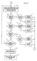
- Figs. 2A-2D is a flow chart showing the Product Architecture Retrieval Information Software 13.
- This program begins in decision block 100 of Fig. 2A.
- Block 100 determines whether the user of computer 29 requested product or component information. If the user of computer 29 requested component information, the program will proceed to block 108 of Fig 2C. If block 100 determines that a user of computer 29 requested product information, then the program will go to block 101.
- Block 101 will select one or more products, either directly or with respect to the product family, product code number, business segment, market segment, and/or product type. After making one of the above selections, the program will go to decision to block 102.
- Decision block 102 will determine whether or not to display the product specification(s) on a display 30. If Block 102 determines to display the product specification(s), then the program goes to block 103 to open the read-only copy of the latest base line specification(s). If Block 102 determines not to display the product specification(s), then the program goes to decision block 104.
- Decision Block 104 determines whether or not to display the product architecture(s). If Block 104 determines to display the product architecture(s), then the program goes to block 150 of Fig. 2B. Block 150 graphically displays the functional architecture with physical decomposition. Then the program goes to block 151 to display the attributes of the selected component. Now the program goes to decision to block 152. Block 152 determines whether one not to display the attributes of another component. If Block 152 determines not to display the attributes of another component, then the program goes back to the input of block 150. If Block 152 decides to display the attribute of another component, then the program goes to block 153 to select the component. At this point, the program will go back to the input of block 150.
- Block 104 determines not to display the product architecture(s)
- the program goes to decision block 105.
- Decision block 105 compares the product functions. If the product functions are the same, the program goes to block 106 to display the product functions. If the product functions are not the same, the program goes to decision block 107.
- Decision block 107 determines whether or not to display the query product attributes. If block 107 determines not to display the query product attributes, then the program goes back to block 101. If block 107 determines to display the query product attributes, then the program goes to block 200 (Fig. 2D).
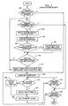
- block component display 108 receives an input from decision block 100.
- Block 108 displays the lists of products and associated modules, devices, device types, part categories and parts.
- the program goes to decision block 109.
- Block 109 determines whether or not to display the query on a module will level. If block 109 determines to display the query on a module level, then the program goes to decision block 110.
- Decision block 110 determines whether or not to only display the standard module. If Block 110 determines to display the standard module, then the program goes to block 111 to select the standard modules. At this point, the program will go to block 200 (See Fig. 2D). If Block 110 determines not to display the standard module, then the program goes to block 112 to select the selected modules. At this point, the program will go to block 200 (Fig. 2D).
- Block 109 determines not to display or query on a module level
- the program goes to decision block 113.
- Decision block 113 determines whether or not to display or query on a device level. If Block 113 determines to display or query on a device level, then the program goes to decision block 114. If block 114 determines only to display the standard device, then the program goes to block 115 to select the standard devices. At this point, the program will go to block 200 (Fig. 2D). If Block 114 determines not to display the selected device(s), then the program goes to block 116 to select the selected device(s). At this point, the program will go to block 200 (Fig. 2D). If Block 113 determines not to display or query on a device level, the program goes to decision block 117.
- Decision block 117 determines whether or not to display or query on a parts level. If Block 117 determines to display or query on a parts level, then the program goes to decision block 118. If block 114 determines only to display the standard parts, then the program goes to block 119 to select the standard parts. At this point, the program will go to block 200 (Fig. 2D). If Block 118 determines not to display the standard part(s), then the program goes to block 120 to select the selected pads(s). At this point, the program will go to block 200 (Fig. 2D). If Block 117 determines not to display or query on parts, the program goes to decision block 121.
- Decision block 121 determines whether or not to display the module(s), device(s) or pad(s) specification. If Block 121 determines not to display the module(s), device(s) or part(s) specifications, the program goes back to the input of block 108. If Block 121 determines to display the module(s), device(s) or pad(s) specifications, the program goes to block 122 to select the module(s), device(s) or pad(s). Now the program goes to block 1243 to open the read-only copy of the latest base line specification(s).
- block 200 receives an input from decision block 107.
- Block 107 displays the applicable attribute categories and attribute names for selected product(s) or selected component(s).
- the program goes to block 101 to select one attribute category or all attributes categories.
- the program goes to block 202 to select one or more attribute names associated with the attribute category.
- the program goes to block to 203 to display the attribute value(s).
- decision block 204 determines whether or not details are needed. If decision block 204 determines that details are needed, then the program goes to block 205 to launch the applicable Computer Aided Engineering (CAE) programs.
- CAE programs are programs that contain additional design details, i.e., additional electrical, electronic, mechanical or electromechanical details.
- Block 206 determines whether or not to display additional attribute values. If block 206 determines to display additional attribute values, then the program goes back to the input of block 201. If block 206 determines not to display additional attribute values, then the program goes to decision block 207. Block 207 determines whether or not to query into the product or component data base. If block 207 determines not to query into the product or component data base, then the program goes back to the input of block 201. If block 206 determines to query into the product or component data base, then the program goes to block 208 to input the queried numerical or textual criteria.
- Decision block 209 determines whether or not to apply the criteria. If block 209 determines not to apply the criteria, then the program goes back to the input of block 208. If block 209 determines to apply the criteria, then the program goes to block 210 to display all match(es) and partial match(es) of the query. Then the program goes to decision block 211. Block 211 determines whether or not additional queries are required. If additional queries are required, then the program goes back to the input of block to 208. If additional queries are not required, then the program goes back to the input of block 210.
- Fig. 3 is a flow chart showing the Architecture Wizard Software 14.
- the program begins at start and then goes to decision block 250.
- Decision block 250 determines whether or not to revise the existing Product Architecture Retrieval Information Software (PARIS) 13 modules, devices or parts. If block 250 determines not to revise the existing modules, devices or parts, the program goes to block 258. If block 250 determines to revise the existing modules, devices or parts, the program goes to decision block 251.
- Block 251 determines whether or not software 14 finished analyzing all software 13 components. If block 251 determines that all the software 13 components have been analyzed, the program goes to block 264. If block 251 determines that all the software 13 components have not been analyzed, the program goes to block 252 to select the existing module(s), device(s) or part(s). Now the program goes to block 253 to view the attributes of the selected component.
- PARIS Product Architecture Retrieval Information Software
- Block 254 determines whether or not to add or modify the attributes of the selected component. If block 254 determines that the attributes of the selected component should be modified, the program goes to block 255 to create a new software 13 component with modified attributes. Then the program goes to the input of decision block 256. If block 254 determines that the attributes of the selected component should not be modified, the program goes to decision block 256. Block 256 determines whether or not to use the selected component for this new architecture. If block 256 determines not to use the selected component for the new architecture, the program goes back to the input of block 251.
- block 256 determines to use the selected component for the new architecture, the program goes block 257 to insert the component into the graphical representation of the architecture which will be displayed on displays 29 and which may be printed on printers 31. Then the program goes back to the input of block 251.
- Block 258 names the new component. Then the program goes to decision block 259.
- Block 259 determines whether or not to re-use software 13 attributes. If block 259 determines to re-use software 13 attributes, the program goes to block 260 to access software 13 attributes. At this point the program goes to block 262. If block 259 determines not to reuse software 13 attributes, the program goes to block 261 to create new software 13 attributes. Then the program goes to block 262 to set attribute values. Now the program goes to decision block 263.
- Block 263 determines whether or not the attribute definition has been finished. If the attribute definition has not been finished, the program goes back to the input of block 259.
- Block 264 determines whether or not the component definition has been finished. If the component definition has not been finished, the program goes back to the input of block 258. If the component definition has been finished, the program exits.
Abstract
Description
- This invention relates generally to the field of computer systems and more particularly to the field of computer aided engineering design and decision systems.
- Reference is made to European Patent Application Number (Attorney File No. 80 258, Applicant Docket No. E-759), entitled A METHOD AND SYSTEM FOR CREATING A RULES-BASED DOCUMENT, assigned to the assignee of this application and filed on even date herewith.
- Engineering is the art of directing the great sources of power in nature for the use and convenience of humans. The process by which these goals are achieved is engineering design. Engineering design commences upon the recognition of the need to satisfy some human want or desire, which might range from the detection and destruction of incoming aircraft to the design of some type of fastener, i.e., a special type of screw.
- The first obligation of the engineer is to develop more detailed, quantitative information which defines the human want or task to be accomplished in order to formulate the task as a specification. At this point, the scope of the problem is defined and the need for pertinent information is established. In many engineering situations, particularly those where there is a great body of experience residing in a company that has previously designed similar products, models or systems, a large amount of this experience or expertise is unable to be found or is lost. Consequently, many existing components are needlessly redesigned or modified, even when no change is required.
- The forgoing problem is exacerbated when inexperienced or new engineers are assigned to design the product, model or system. This often causes additional time and expense to design the product. Oftentimes, the product does not function as well as was expected. Furthermore, some apparently inconsequential design changes to components of systems will greatly affect other components of the system. Engineering design changes may also affect: the cost and difficulty of manufacturing the product; the ability to sell the product; the ability to service the project and the reliability of the product.
- This specification addresses the disadvantages of the prior art and describes a system and method that enables inexperienced or new engineers or engineers that do not have a complete knowledge of the available knowledge to automatically use the experience and designs that have previously been used by experienced engineers in the organization. The engineering user of this system is able to identify requirements, components (product building blocks), documentation, processes, test, historical data, etc., as candidates for reuse. This is accomplished by parsing the required information automatically from product and component specifications.
- The foregoing lowers the development cost of components, while improving the quality of the product. The time required to design the product is also reduced. Consequently, new products may be brought to market faster. In addition, an "Architecture Wizard" provides the ability to graphically specify architectures from scratch and/or use existing architectures (components and their associated attributes).
- For a better understanding of the invention and to show how the same may be carried into effect, reference will now be made, by way of example, to the accompanying drawings, in which:
- Fig. 1 is a block diagram of a system according to one embodiment of this invention;
- Figs. 2A-2D is a flow chart showing Product Architecture Retrieval Information Software 13; and
- Fig. 3 is a flow chart showing Architecture Wizard Software 14.
-
- Referring now to the drawings in detail, and more particularly to Fig. 1, the
reference character 11 represents a server.Server 11 contains: DOORS Software 12; Product Architecture Retrieval Information Software (PARIS) 13; Architecture Wizard Software 14; and Product Information Data Base 15. Product Specifications are transmitted fromsoftware 12 tosoftware 13 viacommunications path 16 and component specifications are transmitted fromsoftware 12 tosoftware 13 viacommunications path 17. Product attributes data is transmitted fromsoftware 12 tosoftware 13 viacommunications path 18 and component attributes data is transmitted fromsoftware 12 tosoftware 13 viacommunications path 19. Product functions data is transmitted fromsoftware 12 tosoftware 13 viacommunications path 20 and product architecture data is transmitted fromsoftware 12 tosoftware 13 viacommunications path 21. Standard components data is transmitted fromsoftware 12 tosoftware 13 viacommunications path 22, and product and component queries are transmitted fromsoftware 13 tosoftware 12 viacommunications path 23. Existing product components data is transmitted fromsoftware 12 tosoftware 14 viacommunications path 24 and existing product attributes data is transmitted fromsoftware 14 tosoftware 12 viacommunications path 25. New Product architecture data is transmitted fromsoftware 12 tosoftware 14 viacommunications path 26 and new components data is transmitted fromsoftware 12 tosoftware 14 viacommunications path 27. New attributes data is transmitted fromsoftware 12 tosoftware 14 viacommunications path 28. A plurality ofcomputers 29 having displays 30,printers 31 andinput output devices 32 are coupled toserver 11. - DOORS Software 12 provides a secure, controlled environment for information management.
Software 12 establishes relationships between parts of project documentation and permits teams working at multiple locations to use the same database concurrently.Software 12 is manufactured by Quality Systems & Software Ltd. of 200 Valley Road, Suite 306, Mt. Arlington, New Jersey 07856 USA.Software 13 controls the display of the existing building blocks of the product components in graphical form or textual form ondisplays 32.Software 13 is described in the description of Figs. 2A-2D.Architecture wizard software 14 specifies the product componentarchitecture using software 13 based building blocks.Software 14 is described in the description of Fig. 4.Product information database 15 contains information about product components that is not contained withinsoftware 12. - Figs. 2A-2D is a flow chart showing the Product Architecture Retrieval Information Software 13. This program begins in
decision block 100 of Fig. 2A.Block 100 determines whether the user ofcomputer 29 requested product or component information. If the user ofcomputer 29 requested component information, the program will proceed to block 108 of Fig 2C. Ifblock 100 determines that a user ofcomputer 29 requested product information, then the program will go to block 101. Block 101 will select one or more products, either directly or with respect to the product family, product code number, business segment, market segment, and/or product type. After making one of the above selections, the program will go to decision to block 102.Decision block 102 will determine whether or not to display the product specification(s) on adisplay 30. IfBlock 102 determines to display the product specification(s), then the program goes to block 103 to open the read-only copy of the latest base line specification(s). IfBlock 102 determines not to display the product specification(s), then the program goes todecision block 104. -
Decision Block 104 determines whether or not to display the product architecture(s). If Block 104 determines to display the product architecture(s), then the program goes to block 150 of Fig. 2B.Block 150 graphically displays the functional architecture with physical decomposition. Then the program goes to block 151 to display the attributes of the selected component. Now the program goes to decision to block 152.Block 152 determines whether one not to display the attributes of another component. IfBlock 152 determines not to display the attributes of another component, then the program goes back to the input ofblock 150. IfBlock 152 decides to display the attribute of another component, then the program goes to block 153 to select the component. At this point, the program will go back to the input ofblock 150. - If
Block 104 determines not to display the product architecture(s), then the program goes todecision block 105.Decision block 105 compares the product functions. If the product functions are the same, the program goes to block 106 to display the product functions. If the product functions are not the same, the program goes todecision block 107.Decision block 107 determines whether or not to display the query product attributes. Ifblock 107 determines not to display the query product attributes, then the program goes back to block 101. Ifblock 107 determines to display the query product attributes, then the program goes to block 200 (Fig. 2D). - In Fig. 2C,
block component display 108 receives an input fromdecision block 100. Block 108 displays the lists of products and associated modules, devices, device types, part categories and parts. Now the program goes todecision block 109.Block 109 determines whether or not to display the query on a module will level. Ifblock 109 determines to display the query on a module level, then the program goes todecision block 110.Decision block 110 determines whether or not to only display the standard module. IfBlock 110 determines to display the standard module, then the program goes to block 111 to select the standard modules. At this point, the program will go to block 200 (See Fig. 2D). IfBlock 110 determines not to display the standard module, then the program goes to block 112 to select the selected modules. At this point, the program will go to block 200 (Fig. 2D). - If
block 109 determines not to display or query on a module level, then the program goes todecision block 113.Decision block 113 determines whether or not to display or query on a device level. IfBlock 113 determines to display or query on a device level, then the program goes todecision block 114. Ifblock 114 determines only to display the standard device, then the program goes to block 115 to select the standard devices. At this point, the program will go to block 200 (Fig. 2D). IfBlock 114 determines not to display the selected device(s), then the program goes to block 116 to select the selected device(s). At this point, the program will go to block 200 (Fig. 2D). IfBlock 113 determines not to display or query on a device level, the program goes todecision block 117. -
Decision block 117 determines whether or not to display or query on a parts level. IfBlock 117 determines to display or query on a parts level, then the program goes todecision block 118. Ifblock 114 determines only to display the standard parts, then the program goes to block 119 to select the standard parts. At this point, the program will go to block 200 (Fig. 2D). IfBlock 118 determines not to display the standard part(s), then the program goes to block 120 to select the selected pads(s). At this point, the program will go to block 200 (Fig. 2D). IfBlock 117 determines not to display or query on parts, the program goes todecision block 121. -
Decision block 121 determines whether or not to display the module(s), device(s) or pad(s) specification. IfBlock 121 determines not to display the module(s), device(s) or part(s) specifications, the program goes back to the input ofblock 108. IfBlock 121 determines to display the module(s), device(s) or pad(s) specifications, the program goes to block 122 to select the module(s), device(s) or pad(s). Now the program goes to block 1243 to open the read-only copy of the latest base line specification(s). - In Fig. 2D, block 200 receives an input from
decision block 107. Block 107 displays the applicable attribute categories and attribute names for selected product(s) or selected component(s). Now the program goes to block 101 to select one attribute category or all attributes categories. Then the program goes to block 202 to select one or more attribute names associated with the attribute category. Then the program goes to block to 203 to display the attribute value(s). Then the program goes todecision block 204.Decision block 204 determines whether or not details are needed. Ifdecision block 204 determines that details are needed, then the program goes to block 205 to launch the applicable Computer Aided Engineering (CAE) programs. CAE programs are programs that contain additional design details, i.e., additional electrical, electronic, mechanical or electromechanical details. - If
decision block 204 determines that details are not needed, then the program goes todecision block 206.Block 206 determines whether or not to display additional attribute values. Ifblock 206 determines to display additional attribute values, then the program goes back to the input ofblock 201. Ifblock 206 determines not to display additional attribute values, then the program goes todecision block 207.Block 207 determines whether or not to query into the product or component data base. Ifblock 207 determines not to query into the product or component data base, then the program goes back to the input ofblock 201. Ifblock 206 determines to query into the product or component data base, then the program goes to block 208 to input the queried numerical or textual criteria. - Now the program goes to
decision block 209.Decision block 209 determines whether or not to apply the criteria. Ifblock 209 determines not to apply the criteria, then the program goes back to the input ofblock 208. Ifblock 209 determines to apply the criteria, then the program goes to block 210 to display all match(es) and partial match(es) of the query. Then the program goes todecision block 211.Block 211 determines whether or not additional queries are required. If additional queries are required, then the program goes back to the input of block to 208. If additional queries are not required, then the program goes back to the input ofblock 210. - Fig. 3 is a flow chart showing the
Architecture Wizard Software 14. The program begins at start and then goes todecision block 250.Decision block 250 determines whether or not to revise the existing Product Architecture Retrieval Information Software (PARIS) 13 modules, devices or parts. Ifblock 250 determines not to revise the existing modules, devices or parts, the program goes to block 258. Ifblock 250 determines to revise the existing modules, devices or parts, the program goes todecision block 251.Block 251 determines whether or notsoftware 14 finished analyzing allsoftware 13 components. Ifblock 251 determines that all thesoftware 13 components have been analyzed, the program goes to block 264. Ifblock 251 determines that all thesoftware 13 components have not been analyzed, the program goes to block 252 to select the existing module(s), device(s) or part(s). Now the program goes to block 253 to view the attributes of the selected component. - At this point, the program goes to
decision block 254.Block 254 determines whether or not to add or modify the attributes of the selected component. Ifblock 254 determines that the attributes of the selected component should be modified, the program goes to block 255 to create anew software 13 component with modified attributes. Then the program goes to the input ofdecision block 256. Ifblock 254 determines that the attributes of the selected component should not be modified, the program goes todecision block 256.Block 256 determines whether or not to use the selected component for this new architecture. Ifblock 256 determines not to use the selected component for the new architecture, the program goes back to the input ofblock 251. Ifblock 256 determines to use the selected component for the new architecture, the program goes block 257 to insert the component into the graphical representation of the architecture which will be displayed ondisplays 29 and which may be printed onprinters 31. Then the program goes back to the input ofblock 251. - If
block 250 decides not to re-use the existing PARIS modules, devices or parts.Block 258 names the new component. Then the program goes todecision block 259.Block 259 determines whether or not to re-usesoftware 13 attributes. Ifblock 259 determines to re-usesoftware 13 attributes, the program goes to block 260 to accesssoftware 13 attributes. At this point the program goes to block 262. Ifblock 259 determines not to reusesoftware 13 attributes, the program goes to block 261 to createnew software 13 attributes. Then the program goes to block 262 to set attribute values. Now the program goes todecision block 263.Block 263 determines whether or not the attribute definition has been finished. If the attribute definition has not been finished, the program goes back to the input ofblock 259. If the attribute definition has been finished, the program goes todecision block 264.Decision block 264 is also entered from a positive response ofdecision block 251.Block 264 determines whether or not the component definition has been finished. If the component definition has not been finished, the program goes back to the input ofblock 258. If the component definition has been finished, the program exits. - The above specification describes a new and improved system and method that helps engineers design different systems and equipment. It is realized that the above description may indicate to those skilled in the art additional ways in which the principles of this invention may be used without departing from the scope thereof. It is, therefore, intended that this invention be limited only by the scope of the appended claims.
Claims (10)
- A system for accessing information about components of one or more products that function in certain specified ways, said system comprising:means (12,15,16,17,18,19) for obtaining information regarding characteristics of component parts of one or more of the products that function in certain specified ways;means (12,15,20) for obtaining information regarding functions of component parts of one or more of the products;means (12,15,21) for obtaining information regarding functional architecture of component parts of one or more of the products; andmeans (13) for using the characteristics information, the function information and the functional architecture information of component parts to determine whether or not the component of one or more of the products may be used in the design of the products.
- The system claimed in Claim 1, further including:means for determining whether or not the component is a candidate for reuse.
- The system claimed in Claim 1 or 2, further including:means for determining whether or not the component is a candidate for inclusion in the design of the product.
- The system claimed in Claim 1, 2 or 3 further including:means for determining whether or not the component is a candidate for reuse in a new design of the product.
- The system claimed in any one of the preceding claims, further including:means for determining whether or not the component is a candidate for reuse in a existing design.
- A method for creating and maintaining information about component data bases of a product by a user in a word processed document, the method performed in a word processing system including a programmed computer (29), a display device (30) and an input device (32), the method comprising the steps of:determining needed values of component attributes of products;extracting component attributes from processed documents;placing the extracted attributes into data bases;establishing relationships among components of products in the data bases;displaying the relationships of the product components; anddisplaying attributes about the components of the products contained in the data bases so that one or more of the components may be used in the design of the products.
- The method of Claim 6, further including the step of:permitting users working at multiple locations to access component attributes concurrently.
- The method of Claim 7, further including the step of:permitting users working at multiple locations to access component attributes and relationships of component attributes concurrently.
- The method claimed in Claim 6, 7 or 8, wherein in the extracting step product specifications are supplied.
- The method claimed in any one of Claims 6 to 9, wherein in the extracting step component specifications are supplied.
Applications Claiming Priority (2)
| Application Number | Priority Date | Filing Date | Title |
|---|---|---|---|
| US09/203,878 US6260046B1 (en) | 1998-12-02 | 1998-12-02 | Product architecture retrieval information system |
| US203878 | 1998-12-02 |
Publications (2)
| Publication Number | Publication Date |
|---|---|
| EP1006470A2 true EP1006470A2 (en) | 2000-06-07 |
| EP1006470A3 EP1006470A3 (en) | 2003-12-03 |
Family
ID=22755680
Family Applications (1)
| Application Number | Title | Priority Date | Filing Date |
|---|---|---|---|
| EP99123281A Withdrawn EP1006470A3 (en) | 1998-12-02 | 1999-11-30 | Product architecture retrieval information system |
Country Status (3)
| Country | Link |
|---|---|
| US (1) | US6260046B1 (en) |
| EP (1) | EP1006470A3 (en) |
| JP (1) | JP2000172723A (en) |
Families Citing this family (7)
| Publication number | Priority date | Publication date | Assignee | Title |
|---|---|---|---|---|
| US6768928B1 (en) * | 1999-05-20 | 2004-07-27 | Olympus Optical Co., Ltd. | Mechanism component design support system |
| US6625507B1 (en) * | 2000-02-23 | 2003-09-23 | United Technologies Corporation | Method and system for designing a low pressure turbine shaft |
| US7333975B2 (en) * | 2002-02-25 | 2008-02-19 | John Robert Cain | Information system and method for disseminating technology information |
| US20030212587A1 (en) * | 2002-05-13 | 2003-11-13 | International Business Machines Corporation | Apparatus and methods for coordinating Web services using role based interpretation of coordination plans |
| US20070150240A1 (en) * | 2004-10-07 | 2007-06-28 | Bridson William D | Automated selection of optical systems |
| US7149662B2 (en) * | 2004-10-07 | 2006-12-12 | Navitar, Inc. | Automated selection of optical systems |
| US20090083696A1 (en) * | 2007-09-26 | 2009-03-26 | Electronic Data Systems Corporation | Apparatus, and associated methodology, for planning, modeling, and monitoring a development process |
Citations (2)
| Publication number | Priority date | Publication date | Assignee | Title |
|---|---|---|---|---|
| US5519630A (en) * | 1993-03-22 | 1996-05-21 | Matsushita Electric Industrial Co., Ltd. | LSI automated design system |
| US5552995A (en) * | 1993-11-24 | 1996-09-03 | The Trustees Of The Stevens Institute Of Technology | Concurrent engineering design tool and method |
Family Cites Families (11)
| Publication number | Priority date | Publication date | Assignee | Title |
|---|---|---|---|---|
| US4553206A (en) * | 1983-10-03 | 1985-11-12 | Wang Laboratories, Inc. | Image storage and retrieval |
| JP3201156B2 (en) * | 1993-08-30 | 2001-08-20 | トヨタ自動車株式会社 | Method and apparatus for assisting design |
| US5767848A (en) * | 1994-12-13 | 1998-06-16 | Hitachi, Ltd. | Development support system |
| US5765142A (en) | 1994-08-18 | 1998-06-09 | Creatacard | Method and apparatus for the development and implementation of an interactive customer service system that is dynamically responsive to change in marketing decisions and environments |
| US5838965A (en) * | 1994-11-10 | 1998-11-17 | Cadis, Inc. | Object oriented database management system |
| US5752027A (en) | 1994-11-30 | 1998-05-12 | Dun & Bradstreet Software Services, Inc. | Apparatus and process for creating and accessing a database centric object |
| US5754737A (en) | 1995-06-07 | 1998-05-19 | Microsoft Corporation | System for supporting interactive text correction and user guidance features |
| US5727159A (en) | 1996-04-10 | 1998-03-10 | Kikinis; Dan | System in which a Proxy-Server translates information received from the Internet into a form/format readily usable by low power portable computers |
| US5767854A (en) | 1996-09-27 | 1998-06-16 | Anwar; Mohammed S. | Multidimensional data display and manipulation system and methods for using same |
| US5782466A (en) | 1996-11-08 | 1998-07-21 | Hewlett-Packard Company | Media processing having intermediate finishing operations and a remote output storage location |
| US5880959A (en) * | 1997-11-25 | 1999-03-09 | Voyan Technology | Method for computer-aided design of a product or process |
-
1998
- 1998-12-02 US US09/203,878 patent/US6260046B1/en not_active Expired - Fee Related
-
1999
- 1999-11-30 EP EP99123281A patent/EP1006470A3/en not_active Withdrawn
- 1999-12-02 JP JP34393499A patent/JP2000172723A/en active Pending
Patent Citations (2)
| Publication number | Priority date | Publication date | Assignee | Title |
|---|---|---|---|---|
| US5519630A (en) * | 1993-03-22 | 1996-05-21 | Matsushita Electric Industrial Co., Ltd. | LSI automated design system |
| US5552995A (en) * | 1993-11-24 | 1996-09-03 | The Trustees Of The Stevens Institute Of Technology | Concurrent engineering design tool and method |
Non-Patent Citations (1)
| Title |
|---|
| ALTMEYER J ET AL: "Reuse Of Design Objects In Cad Frameworks" IEEE/ACM INTERNATIONAL CONFERENCE ON COMPUTER-AIDED DESIGN. DIGEST OF TECHNICAL PAPERS (ICCAD). SAN JOSE, NOV. 6 - 10, 1994, LOS ALAMITOS, IEEE COMP. SOC. PRESS, US, 6 November 1994 (1994-11-06), pages 754-761, XP010252195 ISBN: 0-8186-6417-7 * |
Also Published As
| Publication number | Publication date |
|---|---|
| EP1006470A3 (en) | 2003-12-03 |
| US6260046B1 (en) | 2001-07-10 |
| JP2000172723A (en) | 2000-06-23 |
Similar Documents
| Publication | Publication Date | Title |
|---|---|---|
| US6959294B2 (en) | Context-based help engine and dynamic help | |
| US8490054B2 (en) | Software and related software tracking during software modification | |
| US20040186705A1 (en) | Concept word management | |
| US8250532B2 (en) | Efficient development of configurable software systems in a large software development community | |
| US6484310B1 (en) | Patterns for modeling computer component interactions | |
| MXPA04011788A (en) | Learning and using generalized string patterns for information extraction. | |
| JP2004362223A (en) | Information mining system | |
| CN108279954A (en) | A kind of method and device of application program sequence | |
| JP2003296383A (en) | Three-dimensional modeling system | |
| US6260046B1 (en) | Product architecture retrieval information system | |
| US6907434B2 (en) | Message analysis tool | |
| US6345270B1 (en) | Data management system | |
| US20050010597A1 (en) | System and method of determining impact of model changes | |
| US20040051737A1 (en) | Method and system of interface editing and online real-time accessing for a personal mobile device | |
| CN110929526A (en) | Sample generation method and device and electronic equipment | |
| CN110362694A (en) | Data in literature search method, equipment and readable storage medium storing program for executing based on artificial intelligence | |
| CN115757995A (en) | Method and device for processing characteristic-free data label, computer equipment and storage medium | |
| KR100576487B1 (en) | System and method for maintaining componentized content | |
| JP2000172682A (en) | Method and system for creating rule-based document | |
| JP2005173999A (en) | Device, system and method for searching electronic file, program, and recording media | |
| US6799183B2 (en) | Operation assistance method and system and recording medium for storing operation assistance method | |
| Cybulski | Patterns in software requirements reuse | |
| CN114443165A (en) | SQL file checking method and system based on domestic CPU and database | |
| CN1430168B (en) | Object matching management equipment and method, operation terminal and method used for prescribe object | |
| US20030078927A1 (en) | System and method for using web based wizards and tools |
Legal Events
| Date | Code | Title | Description |
|---|---|---|---|
| PUAI | Public reference made under article 153(3) epc to a published international application that has entered the european phase |
Free format text: ORIGINAL CODE: 0009012 |
|
| AK | Designated contracting states |
Kind code of ref document: A2 Designated state(s): AT BE CH CY DE DK ES FI FR GB GR IE IT LI LU MC NL PT SE |
|
| AX | Request for extension of the european patent |
Free format text: AL;LT;LV;MK;RO;SI |
|
| PUAL | Search report despatched |
Free format text: ORIGINAL CODE: 0009013 |
|
| AK | Designated contracting states |
Kind code of ref document: A3 Designated state(s): AT BE CH CY DE DK ES FI FR GB GR IE IT LI LU MC NL PT SE |
|
| AX | Request for extension of the european patent |
Extension state: AL LT LV MK RO SI |
|
| RIC1 | Information provided on ipc code assigned before grant |
Ipc: 7G 06F 17/50 A |
|
| 17P | Request for examination filed |
Effective date: 20040527 |
|
| AKX | Designation fees paid |
Designated state(s): DE FR GB |
|
| 17Q | First examination report despatched |
Effective date: 20040727 |
|
| 17Q | First examination report despatched |
Effective date: 20040727 |
|
| STAA | Information on the status of an ep patent application or granted ep patent |
Free format text: STATUS: THE APPLICATION HAS BEEN WITHDRAWN |
|
| 18W | Application withdrawn |
Effective date: 20100520 |