EP1006703A2 - Portable electronic device - Google Patents
Portable electronic device Download PDFInfo
- Publication number
- EP1006703A2 EP1006703A2 EP99309346A EP99309346A EP1006703A2 EP 1006703 A2 EP1006703 A2 EP 1006703A2 EP 99309346 A EP99309346 A EP 99309346A EP 99309346 A EP99309346 A EP 99309346A EP 1006703 A2 EP1006703 A2 EP 1006703A2
- Authority
- EP
- European Patent Office
- Prior art keywords
- processor
- connector
- electronic device
- contact
- status
- Prior art date
- Legal status (The legal status is an assumption and is not a legal conclusion. Google has not performed a legal analysis and makes no representation as to the accuracy of the status listed.)
- Withdrawn
Links
Images

Classifications
-
- H—ELECTRICITY
- H01—ELECTRIC ELEMENTS
- H01R—ELECTRICALLY-CONDUCTIVE CONNECTIONS; STRUCTURAL ASSOCIATIONS OF A PLURALITY OF MUTUALLY-INSULATED ELECTRICAL CONNECTING ELEMENTS; COUPLING DEVICES; CURRENT COLLECTORS
- H01R24/00—Two-part coupling devices, or either of their cooperating parts, characterised by their overall structure
- H01R24/86—Parallel contacts arranged about a common axis
-
- H—ELECTRICITY
- H01—ELECTRIC ELEMENTS
- H01R—ELECTRICALLY-CONDUCTIVE CONNECTIONS; STRUCTURAL ASSOCIATIONS OF A PLURALITY OF MUTUALLY-INSULATED ELECTRICAL CONNECTING ELEMENTS; COUPLING DEVICES; CURRENT COLLECTORS
- H01R24/00—Two-part coupling devices, or either of their cooperating parts, characterised by their overall structure
-
- H—ELECTRICITY
- H04—ELECTRIC COMMUNICATION TECHNIQUE
- H04B—TRANSMISSION
- H04B1/00—Details of transmission systems, not covered by a single one of groups H04B3/00 - H04B13/00; Details of transmission systems not characterised by the medium used for transmission
- H04B1/38—Transceivers, i.e. devices in which transmitter and receiver form a structural unit and in which at least one part is used for functions of transmitting and receiving
- H04B1/3827—Portable transceivers
- H04B1/3877—Arrangements for enabling portable transceivers to be used in a fixed position, e.g. cradles or boosters
-
- H—ELECTRICITY
- H04—ELECTRIC COMMUNICATION TECHNIQUE
- H04M—TELEPHONIC COMMUNICATION
- H04M1/00—Substation equipment, e.g. for use by subscribers
- H04M1/72—Mobile telephones; Cordless telephones, i.e. devices for establishing wireless links to base stations without route selection
- H04M1/724—User interfaces specially adapted for cordless or mobile telephones
- H04M1/72403—User interfaces specially adapted for cordless or mobile telephones with means for local support of applications that increase the functionality
- H04M1/72409—User interfaces specially adapted for cordless or mobile telephones with means for local support of applications that increase the functionality by interfacing with external accessories
-
- H—ELECTRICITY
- H01—ELECTRIC ELEMENTS
- H01R—ELECTRICALLY-CONDUCTIVE CONNECTIONS; STRUCTURAL ASSOCIATIONS OF A PLURALITY OF MUTUALLY-INSULATED ELECTRICAL CONNECTING ELEMENTS; COUPLING DEVICES; CURRENT COLLECTORS
- H01R2201/00—Connectors or connections adapted for particular applications
- H01R2201/16—Connectors or connections adapted for particular applications for telephony
Definitions
- This invention relates to an electronic device and in particular to device having a connector for connecting an external device to the electronic device.
- Connectors are therefore provided for allowing this. It is usual for a connector to be provided for each device to be connected.
- an electronic device comprising a processor and a connector for connecting an external device to the electronic device, the connector having a plurality of electrical contacts at least one of which is connected to the processor, the processor being arranged to monitor the status of at least a first electrical contact and to determine the type of external device connected to the connector in dependence on the status of the first electrical contact.
- a single connector may be provided which is suitable for connecting any one of a plurality of external devices, such as a charger or external power supply, a headset, a data device, an antenna or the like.
- external devices such as a charger or external power supply, a headset, a data device, an antenna or the like.
- Such a connector is relatively compact which is also desirable with portable electronic devices for which the tendency is for smaller and smaller devices.
- the processor is arranged to monitor the status of the first contact in response to a signal from a second electrical contact.
- This second contact may simply be in the form of a switch which operates when the connector of an external device is connected to the connector of the electronic device.
- the processor therefore only needs to monitor the status of the first contact when the switch is triggered.
- the processor is arranged to monitor the voltage of the first contact.
- the processor may be arranged to configure itself in dependence on the type of external device deemed to be connected to the electronic device.
- the processor may configure another component of the electronic device in dependence on the type of external device deemed to be connected.
- Information relating to configuration of the electronic device for specified external devices is preferably stored in memory means.
- this memory means is RAM so that further configuration details may be added as required.
- a processor for receiving signals from a connector, the processor being arranged to monitor the status of at least a first electrical contact of the connector and to determine the type of external device connected to the connector in dependence on the status of the first electrical contact.
- the processor is arranged to configure a device controlled by the processor in dependence on the type of external device deemed to be connected.
- the connector 2 comprises a female body 22 and five electrical connectors 23, 24, 25, 26, 27.
- a protuberance 28 is provided to ensure that the corresponding electrical contacts of a male connector which is to be connected to the female connector 2 are orientated in the correct position.
- the electrical connectors 23 to 27 are disposed inside the perimeter of the connector body 22.
- the connector could have a male body.
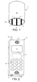
- FIG. 2 shows an electronic device according to the invention.
- the electronic device shown is a radio telephone but the invention is applicable to any electronic device. Some examples, without limitation, are personal organisers, computers, cameras, personal digital assistants etc.
- the radio (or mobile) telephone 3 has a connector 2, a processor 4, a display 6, a speaker 8, a microphone 10, an antenna 12 and a keypad 14.
- FIG 3 shows in detail the arrangement of the processor 4 and the connector 2.
- Figure 3 only relates to those features of the processor that are particular to the present invention.
- the processor also carries out functions for the conventional operation of the device that are not illustrated here.
- At least one of the electrical contacts 23, 24, 25, 26, 27 of the connector is connected to the processor 4.
- the processor 4 is associated with a power supply 16 of 1.8V which is connected to the contact 23 via a diode 18 which prevents the flow of current back towards the power supply 16.
- Contact 27 is connected to 0V.
- the remaining contacts 24, 25, 26 are connected to the processor 4 which controls signals to and from these contacts in a manner to be described below.
- the processor 4 monitors the voltage of the contact 23 and determines the type of external device connected to the electronic device via the connector 2.
- the most usual external devices that may be connected thereto are a headset, a charger for charging the battery (not shown) of the telephone and a data device such as a computer.
- the invention will be described with reference to these types of external device although other devices may be connected.
- the connector 2 is provided with sufficient contacts to cater for all expected types of external devices.
- the processor has configuration information relating to the signal (if any) to be associated with each contact of the connector 2.
- Table 1 shows an example of expected voltages on contact 23 for a mobile telephone and the device assumed therefrom: ⁇ 1.8V Headset 5V Data device >5V Charger
- Jbus is a data transfer interface used mainly in mobile phones manufactured for the Japanese market, which allows subscriber details to be downloaded into the memory of a mobile telephone.
- USB Universal Serial Bus
- USB is the well-known duplex interface used to transfer data between devices such as computers and printers, facsimile machines, telephones etc.
- the processor 4 monitors the voltage of the contact 23 and, in dependence on the voltage measured, determines whether an external device is a headset, a data device or a charger. Rather than continuously monitoring the voltage of the contact 23, a switch contact 25 is provided. When an external device is connected to the connector 2, a signal is passed to the processor 4 which causes the processor 4 to monitor the voltage of contact 23 and so determine the type of external device which has been connected.
- the processor then configures itself as to the signals to be received and transmitted via the remaining contacts 24, 26.
- the configurations are as follows: Contact No. Headset Jbus US B Charger 24 Out - earpiece In - receive D+ In - PWDO (pulse width modulated output from charger) 26 In - microphone Out - transmit D- No connection
- the processor or device is therefore configured such that the signals from or to the contacts 24 and 26 are dealt with appropriately with regard to the external device.
- the voltage on contact 23 becomes 1.8V.
- the processor 4 which then configures itself according to the characteristics for a headset i.e. that signals to the earpiece of the headset are to be sent via contact 24 and signals from the microphone of the headset are to be received via contact 26.
- the voltage on contact 23 becomes 5V. This is detected by the processor 4 which then sends an acknowledge signal to the data device via contact 26 to ask the data device to identify itself.
- the processor then configures itself according to the characteristics for the identified data device e.g. for Jbus, signals to the data device are to be sent via contact 26 and signals from the data device are to be received via contact 24.
- the processor treats signals from the data device appropriately.
- the voltage on contact 23 becomes more than 5V. This is detected by the processor 4 which then configures itself according to the characteristics for a charger i.e. that a charging signal from the charger is to be received via contact 24 and that this signal is to be directed to a charge switch 20.
- the information shown in tables 1 and 2 is stored in a memory 22 associated with the processor 4.
- This memory which is preferably RAM, may also be used to store other information of use to the processor 4.
- the invention has been described with reference to a mobile telephone to which a headset, a charger or a data device may be connected, it will be appreciated that the invention is applicable to any electronic device which requires interconnectivity with an external device.
- the device is configured dynamically in response to the connection of an external device and its subsequent identification.
Abstract
Description
- This invention relates to an electronic device and in particular to device having a connector for connecting an external device to the electronic device.
- In the electronics industry today there is the need for interconnectability between devices. Connectors are therefore provided for allowing this. It is usual for a connector to be provided for each device to be connected.
- According to the invention there is provided an electronic device comprising a processor and a connector for connecting an external device to the electronic device, the connector having a plurality of electrical contacts at least one of which is connected to the processor, the processor being arranged to monitor the status of at least a first electrical contact and to determine the type of external device connected to the connector in dependence on the status of the first electrical contact.
- Thus a single connector may be provided which is suitable for connecting any one of a plurality of external devices, such as a charger or external power supply, a headset, a data device, an antenna or the like. Such a connector is relatively compact which is also desirable with portable electronic devices for which the tendency is for smaller and smaller devices.
- Preferably the processor is arranged to monitor the status of the first contact in response to a signal from a second electrical contact. This second contact may simply be in the form of a switch which operates when the connector of an external device is connected to the connector of the electronic device. Thus the processor therefore only needs to monitor the status of the first contact when the switch is triggered.
- Preferably the processor is arranged to monitor the voltage of the first contact.
- The processor may be arranged to configure itself in dependence on the type of external device deemed to be connected to the electronic device. Alternatively the processor may configure another component of the electronic device in dependence on the type of external device deemed to be connected.
- Information relating to configuration of the electronic device for specified external devices is preferably stored in memory means. Preferably this memory means is RAM so that further configuration details may be added as required.
- According to a second aspect of the invention a processor is provided for receiving signals from a connector, the processor being arranged to monitor the status of at least a first electrical contact of the connector and to determine the type of external device connected to the connector in dependence on the status of the first electrical contact.
- Preferably the processor is arranged to configure a device controlled by the processor in dependence on the type of external device deemed to be connected.
- The invention will now be described by way of example only with reference to the accompanying drawings, in which:
- Figure 1 shows a connector according to the invention;
- Figure 2 shows an electronic device according to the invention; and
- Figure 3 shows the arrangement of the processor of the electronic device and the connector shown in Figure 1.
-
- As shown in Figure 1 the
connector 2 comprises afemale body 22 and fiveelectrical connectors protuberance 28 is provided to ensure that the corresponding electrical contacts of a male connector which is to be connected to thefemale connector 2 are orientated in the correct position. Theelectrical connectors 23 to 27 are disposed inside the perimeter of theconnector body 22. Clearly the connector could have a male body. - Figure 2 shows an electronic device according to the invention. The electronic device shown is a radio telephone but the invention is applicable to any electronic device. Some examples, without limitation, are personal organisers, computers, cameras, personal digital assistants etc. The radio (or mobile)
telephone 3 has aconnector 2, aprocessor 4, adisplay 6, aspeaker 8, amicrophone 10, anantenna 12 and akeypad 14. - Figure 3 shows in detail the arrangement of the
processor 4 and theconnector 2. Figure 3 only relates to those features of the processor that are particular to the present invention. Clearly the processor also carries out functions for the conventional operation of the device that are not illustrated here. At least one of theelectrical contacts processor 4. Theprocessor 4 is associated with apower supply 16 of 1.8V which is connected to thecontact 23 via adiode 18 which prevents the flow of current back towards thepower supply 16.Contact 27 is connected to 0V. Theremaining contacts processor 4 which controls signals to and from these contacts in a manner to be described below. - The
processor 4 monitors the voltage of thecontact 23 and determines the type of external device connected to the electronic device via theconnector 2. In the case of a mobile telephone as shown in Figure 2, the most usual external devices that may be connected thereto are a headset, a charger for charging the battery (not shown) of the telephone and a data device such as a computer. The invention will be described with reference to these types of external device although other devices may be connected. - The
connector 2 is provided with sufficient contacts to cater for all expected types of external devices. For each type of external device which may be connected to thedevice 3, the processor has configuration information relating to the signal (if any) to be associated with each contact of theconnector 2. - Table 1 shows an example of expected voltages on
contact 23 for a mobile telephone and the device assumed therefrom:<1.8V Headset 5V Data device >5V Charger - The type of data device interface is conventionally Jbus or USB. Jbus is a data transfer interface used mainly in mobile phones manufactured for the Japanese market, which allows subscriber details to be downloaded into the memory of a mobile telephone. USB (Universal Serial Bus) is the well-known duplex interface used to transfer data between devices such as computers and printers, facsimile machines, telephones etc.
- Thus the
processor 4 monitors the voltage of thecontact 23 and, in dependence on the voltage measured, determines whether an external device is a headset, a data device or a charger. Rather than continuously monitoring the voltage of thecontact 23, aswitch contact 25 is provided. When an external device is connected to theconnector 2, a signal is passed to theprocessor 4 which causes theprocessor 4 to monitor the voltage ofcontact 23 and so determine the type of external device which has been connected. - Once the processor has determined the type of external device, the processor then configures itself as to the signals to be received and transmitted via the
remaining contacts Contact No. Headset Jbus US B Charger 24 Out - earpiece In - receive D+ In - PWDO (pulse width modulated output from charger) 26 In - microphone Out - transmit D- No connection - The processor or device is therefore configured such that the signals from or to the
contacts contact 23 becomes 1.8V. This is detected by theprocessor 4 which then configures itself according to the characteristics for a headset i.e. that signals to the earpiece of the headset are to be sent viacontact 24 and signals from the microphone of the headset are to be received viacontact 26. - When a data device is connected, the voltage on
contact 23 becomes 5V. This is detected by theprocessor 4 which then sends an acknowledge signal to the data device viacontact 26 to ask the data device to identify itself. The processor then configures itself according to the characteristics for the identified data device e.g. for Jbus, signals to the data device are to be sent viacontact 26 and signals from the data device are to be received viacontact 24. The processor then treats signals from the data device appropriately. - When a charger is connected, the voltage on
contact 23 becomes more than 5V. This is detected by theprocessor 4 which then configures itself according to the characteristics for a charger i.e. that a charging signal from the charger is to be received viacontact 24 and that this signal is to be directed to acharge switch 20. - The information shown in tables 1 and 2 is stored in a
memory 22 associated with theprocessor 4. This memory, which is preferably RAM, may also be used to store other information of use to theprocessor 4. - Preferably the elements shown in Figure 3 are implemented as an integrated circuit.
- Although the invention has been described with reference to a mobile telephone to which a headset, a charger or a data device may be connected, it will be appreciated that the invention is applicable to any electronic device which requires interconnectivity with an external device. The device is configured dynamically in response to the connection of an external device and its subsequent identification.
Claims (12)
- An electronic device comprising a processor and a connector for connecting an external device to the electronic device, the connector having a plurality of electrical contacts at least one of which is connected to the processor, the processor being arranged to monitor the status of at least a first electrical contact and to determine the type of external device connected to the connector in dependence on the status of the first electrical contact.
- An electronic device according to claim 1 wherein the processor is arranged to monitor the status of the first contact in response to a signal from a second electrical contact.
- An electronic device according to claim 1 or 2 wherein the processor is arranged to monitor the voltage of the first contact.
- An electronic device according to claim 1, 2 or 3 wherein the processor is further arranged to configure itself in dependence on the type of external device deemed to be connected to the electronic device.
- An electronic device according to any preceding claim further including memory means for storing information relating to configuration of the electronic device for specified external devices.
- A device according to any preceding claim wherein the device is configured to be connected to a headset, a charger or a data device.
- A device according to any preceding claim wherein the device is a portable device.
- A device according to any preceding claim wherein the device is a radio telephone.
- A processor for receiving signals from a connector, the processor being arranged to monitor the status of at least a first electrical contact of a connector and to determine the type of external device connected to the connector in dependence on the status of the first electrical contact.
- A processor according to claim 9 being arranged to configure itself in dependence on the type of external device deemed to be connected.
- A device substantially as described herein with reference to the accompanying drawings.
- A processor substantially as described herein with reference to the accompanying drawings.
Applications Claiming Priority (2)
| Application Number | Priority Date | Filing Date | Title |
|---|---|---|---|
| GB9826277 | 1998-12-01 | ||
| GB9826277A GB2344429A (en) | 1998-12-01 | 1998-12-01 | Electrical device and connector |
Publications (2)
| Publication Number | Publication Date |
|---|---|
| EP1006703A2 true EP1006703A2 (en) | 2000-06-07 |
| EP1006703A3 EP1006703A3 (en) | 2004-02-04 |
Family
ID=10843353
Family Applications (1)
| Application Number | Title | Priority Date | Filing Date |
|---|---|---|---|
| EP99309346A Withdrawn EP1006703A3 (en) | 1998-12-01 | 1999-11-23 | Portable electronic device |
Country Status (4)
| Country | Link |
|---|---|
| US (1) | US6452402B1 (en) |
| EP (1) | EP1006703A3 (en) |
| JP (1) | JP2000171530A (en) |
| GB (1) | GB2344429A (en) |
Cited By (1)
| Publication number | Priority date | Publication date | Assignee | Title |
|---|---|---|---|---|
| EP2051493A1 (en) * | 2007-10-15 | 2009-04-22 | Samsung Electronics Co., Ltd. | Mobile terminal aware of externally connected device and control method for the same |
Families Citing this family (28)
| Publication number | Priority date | Publication date | Assignee | Title |
|---|---|---|---|---|
| US6678536B2 (en) * | 2000-12-07 | 2004-01-13 | Mark Wendell Fletcher | Wireless microphone |
| GB2375273B (en) | 2001-04-30 | 2004-07-07 | Nokia Mobile Phones Ltd | Communication interface for an electronic device |
| EP1315361A1 (en) * | 2001-11-23 | 2003-05-28 | Alcatel | Multiconnector for mobile terminal |
| US6813537B2 (en) * | 2002-11-21 | 2004-11-02 | D-M-E Company | Connection error detection and response |
| EP1457847A3 (en) * | 2003-03-10 | 2010-01-13 | Heidelberger Druckmaschinen Aktiengesellschaft | System and method for identifying modules in a printing machine |
| US6837725B1 (en) | 2004-01-16 | 2005-01-04 | Deere & Company | Connector assembly |
| TWI237987B (en) * | 2004-04-02 | 2005-08-11 | Wistron Neweb Corp | Electronic system and mobile communication apparatus |
| CN1332290C (en) * | 2004-04-09 | 2007-08-15 | 启碁科技股份有限公司 | Electronic system and mobile communicating apparatus thereof |
| TWI263902B (en) * | 2004-09-10 | 2006-10-11 | Mediatek Inc | Multiple apparatuses connection system and the method thereof |
| US7589536B2 (en) * | 2007-01-05 | 2009-09-15 | Apple Inc. | Systems and methods for determining the configuration of electronic connections |
| US7734841B2 (en) * | 2006-06-30 | 2010-06-08 | Palm, Inc. | System and method for providing serial bus connectivity |
| JP5006699B2 (en) * | 2007-05-29 | 2012-08-22 | ルネサスエレクトロニクス株式会社 | Semiconductor device |
| DE102007061483A1 (en) * | 2007-12-20 | 2009-07-02 | Erbe Elektromedizin Gmbh | Surgery Equipment connector system |
| US7802044B2 (en) * | 2008-12-24 | 2010-09-21 | Mediatek Inc. | Pin sharing device and method thereof for a universal asynchronous receiver/transmitter module and a universal serial bus module |
| US8237414B1 (en) | 2009-03-06 | 2012-08-07 | Pericom Semiconductor Corporation | Multi-mode charger device |
| US20100225176A1 (en) | 2009-03-09 | 2010-09-09 | Apple Inc. | Systems and methods for providing protection circuitry to selectively handle multiple cable-types through the same port |
| EP2390969A1 (en) * | 2010-05-26 | 2011-11-30 | Samsung Electronics Co., Ltd. | Connector and interface device |
| EP2577813B1 (en) | 2010-05-28 | 2020-01-22 | Apple Inc. | Dual orientation connector with external contacts |
| US20120254479A1 (en) * | 2011-03-31 | 2012-10-04 | Yoshimichi Matsuoka | System and Method for Supplementing and/or Modifying Operations of a Mobile Computing Device Using a Cover |
| US8799527B2 (en) | 2012-09-07 | 2014-08-05 | Apple Inc. | Data structures for facilitating communication between a host device and an accessory |
| US9293876B2 (en) | 2011-11-07 | 2016-03-22 | Apple Inc. | Techniques for configuring contacts of a connector |
| US8804792B1 (en) | 2012-02-24 | 2014-08-12 | Pericom Semiconductor Corporation | Intermediary signal conditioning device with interruptible detection mode |
| US8724281B2 (en) | 2012-04-25 | 2014-05-13 | Apple Inc. | Techniques for detecting removal of a connector |
| US8891216B2 (en) | 2012-04-25 | 2014-11-18 | Apple Inc. | Techniques for detecting removal of a connector |
| US8966128B1 (en) | 2012-12-13 | 2015-02-24 | Pericom Semiconductor | Auto plug-in and plug-out VGA port detection |
| US9307312B2 (en) | 2013-03-15 | 2016-04-05 | Apple Inc. | Audio accessory with internal clock |
| CN111614819B (en) * | 2020-06-01 | 2022-07-26 | 上海众链科技有限公司 | External intelligent terminal who has external antenna |
| KR102522177B1 (en) * | 2021-04-26 | 2023-04-14 | 현대트랜시스 주식회사 | Input/output device and method for controlling the input/output device |
Citations (4)
| Publication number | Priority date | Publication date | Assignee | Title |
|---|---|---|---|---|
| WO1992020168A1 (en) * | 1991-05-06 | 1992-11-12 | Motorola, Inc. | Digital option select system |
| EP0695071A2 (en) * | 1994-07-25 | 1996-01-31 | International Business Machines Corporation | Selective reconfiguration method and apparatus in a multiple application personal communications device |
| US5535371A (en) * | 1992-02-07 | 1996-07-09 | Dell Usa, L.P. | Portable computer with automatic adaption to different device types on a standard port |
| US5774741A (en) * | 1995-12-30 | 1998-06-30 | Samsung Electronics Co., Ltd. | Portable computer having a port connector for communicating with a variety of optional extension modules |
Family Cites Families (8)
| Publication number | Priority date | Publication date | Assignee | Title |
|---|---|---|---|---|
| US4468612A (en) * | 1982-01-15 | 1984-08-28 | At&T Bell Laboratories | Arrangement for indicating when different types of electrical components are interconnected |
| US4837488A (en) * | 1988-05-06 | 1989-06-06 | Ncr Corporation | Portable identifier and tester units for computer communication cables |
| US5146172A (en) * | 1990-08-15 | 1992-09-08 | Sundstrand Corp. | Engine identification system |
| US5181858A (en) * | 1991-08-30 | 1993-01-26 | Amp Incorporated | Cable type identifying and impedance matching arrangement |
| TW281724B (en) * | 1995-03-06 | 1996-07-21 | Advanced Micro Devices Inc | Apparatus and method to uniquely identify similarly connected electrical devices |
| JPH0974448A (en) * | 1995-09-06 | 1997-03-18 | Sharp Corp | Terminal equipment for mobile telephone set |
| US5742526A (en) * | 1996-01-03 | 1998-04-21 | Micron Technology, Inc. | Apparatus and method for identifying an integrated device |
| US6002331A (en) * | 1998-07-20 | 1999-12-14 | Laor; Herzel | Method and apparatus for identifying and tracking connections of communication lines |
-
1998
- 1998-12-01 GB GB9826277A patent/GB2344429A/en not_active Withdrawn
-
1999
- 1999-11-23 EP EP99309346A patent/EP1006703A3/en not_active Withdrawn
- 1999-12-01 JP JP11342575A patent/JP2000171530A/en not_active Withdrawn
- 1999-12-01 US US09/452,814 patent/US6452402B1/en not_active Expired - Lifetime
Patent Citations (4)
| Publication number | Priority date | Publication date | Assignee | Title |
|---|---|---|---|---|
| WO1992020168A1 (en) * | 1991-05-06 | 1992-11-12 | Motorola, Inc. | Digital option select system |
| US5535371A (en) * | 1992-02-07 | 1996-07-09 | Dell Usa, L.P. | Portable computer with automatic adaption to different device types on a standard port |
| EP0695071A2 (en) * | 1994-07-25 | 1996-01-31 | International Business Machines Corporation | Selective reconfiguration method and apparatus in a multiple application personal communications device |
| US5774741A (en) * | 1995-12-30 | 1998-06-30 | Samsung Electronics Co., Ltd. | Portable computer having a port connector for communicating with a variety of optional extension modules |
Cited By (2)
| Publication number | Priority date | Publication date | Assignee | Title |
|---|---|---|---|---|
| EP2051493A1 (en) * | 2007-10-15 | 2009-04-22 | Samsung Electronics Co., Ltd. | Mobile terminal aware of externally connected device and control method for the same |
| CN101415043B (en) * | 2007-10-15 | 2012-07-11 | 三星电子株式会社 | Mobile terminal aware of externally connected device and control method for the same |
Also Published As
| Publication number | Publication date |
|---|---|
| EP1006703A3 (en) | 2004-02-04 |
| GB9826277D0 (en) | 1999-01-20 |
| GB2344429A (en) | 2000-06-07 |
| JP2000171530A (en) | 2000-06-23 |
| US6452402B1 (en) | 2002-09-17 |
| US20020125893A1 (en) | 2002-09-12 |
Similar Documents
| Publication | Publication Date | Title |
|---|---|---|
| EP1006703A2 (en) | Portable electronic device | |
| US5487099A (en) | Portable telephone having an additional device for making external connections | |
| US7305253B2 (en) | Combination audio/charger jack | |
| US20040198442A1 (en) | Multiple functions transmitting apparatus for mobile phone | |
| US7722370B2 (en) | Socket with detection functions | |
| US20110133691A1 (en) | Wireless Galvanic Charging Device,Method of Operation Thereof and Mobile Electric Device to be Charged | |
| US6298245B1 (en) | IC card-type radio communication device | |
| EP1133185A2 (en) | Mobile imaging | |
| WO2009063278A1 (en) | Multipurpose universal bus cable | |
| EP1361665B1 (en) | Apparatus for supplying power to mobile phone using earphone-microphone connector | |
| US9069538B2 (en) | Preventing dark current flow in a mobile terminal | |
| JP2571162B2 (en) | Mobile phone equipment | |
| US6424842B1 (en) | Dual function connector for cellular phones | |
| FI104920B (en) | Electronic device, card interface and expansion card | |
| JP3909051B2 (en) | Wireless headphones with connection bush | |
| CN111615029A (en) | Wireless earphone reset circuit, wireless earphone and reset method | |
| JP2002116853A (en) | Usb mounted electronic equipment and use cable to be used therefor | |
| JPH08237345A (en) | Charging table and charging and data transmission system for radio telephone equipment | |
| US5336984A (en) | Electronic device powering system | |
| EP0918399B1 (en) | Telecommunications card | |
| JP2005110332A (en) | Cradle of terminal | |
| CN212013016U (en) | Wireless earphone reset circuit and wireless earphone | |
| US6246600B1 (en) | Multi-use battery | |
| JP3500563B2 (en) | Power warning display device for information communication adapter | |
| JP4406257B2 (en) | Mobile device |
Legal Events
| Date | Code | Title | Description |
|---|---|---|---|
| PUAI | Public reference made under article 153(3) epc to a published international application that has entered the european phase |
Free format text: ORIGINAL CODE: 0009012 |
|
| AK | Designated contracting states |
Kind code of ref document: A2 Designated state(s): AT BE CH CY DE DK ES FI FR GB GR IE IT LI LU MC NL PT SE |
|
| AX | Request for extension of the european patent |
Free format text: AL;LT;LV;MK;RO;SI |
|
| RAP1 | Party data changed (applicant data changed or rights of an application transferred) |
Owner name: NOKIA CORPORATION |
|
| PUAL | Search report despatched |
Free format text: ORIGINAL CODE: 0009013 |
|
| AK | Designated contracting states |
Kind code of ref document: A3 Designated state(s): AT BE CH CY DE DK ES FI FR GB GR IE IT LI LU MC NL PT SE |
|
| AX | Request for extension of the european patent |
Extension state: AL LT LV MK RO SI |
|
| RIC1 | Information provided on ipc code assigned before grant |
Ipc: 7H 04M 1/725 B Ipc: 7H 04M 1/02 A |
|
| 17P | Request for examination filed |
Effective date: 20040804 |
|
| AKX | Designation fees paid |
Designated state(s): DE ES FR IT |
|
| STAA | Information on the status of an ep patent application or granted ep patent |
Free format text: STATUS: THE APPLICATION HAS BEEN WITHDRAWN |
|
| 18W | Application withdrawn |
Effective date: 20060512 |