EP1013124B1 - Method and arrangement in a radio communications system - Google Patents
Method and arrangement in a radio communications system Download PDFInfo
- Publication number
- EP1013124B1 EP1013124B1 EP98901611A EP98901611A EP1013124B1 EP 1013124 B1 EP1013124 B1 EP 1013124B1 EP 98901611 A EP98901611 A EP 98901611A EP 98901611 A EP98901611 A EP 98901611A EP 1013124 B1 EP1013124 B1 EP 1013124B1
- Authority
- EP
- European Patent Office
- Prior art keywords
- base station
- mobile stations
- mobile
- msx1
- channel
- Prior art date
- Legal status (The legal status is an assumption and is not a legal conclusion. Google has not performed a legal analysis and makes no representation as to the accuracy of the status listed.)
- Expired - Lifetime
Links
Images


Classifications
-
- H—ELECTRICITY
- H04—ELECTRIC COMMUNICATION TECHNIQUE
- H04W—WIRELESS COMMUNICATION NETWORKS
- H04W52/00—Power management, e.g. TPC [Transmission Power Control], power saving or power classes
- H04W52/04—TPC
- H04W52/38—TPC being performed in particular situations
- H04W52/50—TPC being performed in particular situations at the moment of starting communication in a multiple access environment
-
- H—ELECTRICITY
- H04—ELECTRIC COMMUNICATION TECHNIQUE
- H04W—WIRELESS COMMUNICATION NETWORKS
- H04W72/00—Local resource management
- H04W72/20—Control channels or signalling for resource management
- H04W72/23—Control channels or signalling for resource management in the downlink direction of a wireless link, i.e. towards a terminal
-
- H—ELECTRICITY
- H04—ELECTRIC COMMUNICATION TECHNIQUE
- H04W—WIRELESS COMMUNICATION NETWORKS
- H04W16/00—Network planning, e.g. coverage or traffic planning tools; Network deployment, e.g. resource partitioning or cells structures
- H04W16/24—Cell structures
-
- H—ELECTRICITY
- H04—ELECTRIC COMMUNICATION TECHNIQUE
- H04W—WIRELESS COMMUNICATION NETWORKS
- H04W28/00—Network traffic management; Network resource management
- H04W28/16—Central resource management; Negotiation of resources or communication parameters, e.g. negotiating bandwidth or QoS [Quality of Service]
- H04W28/26—Resource reservation
-
- H—ELECTRICITY
- H04—ELECTRIC COMMUNICATION TECHNIQUE
- H04W—WIRELESS COMMUNICATION NETWORKS
- H04W64/00—Locating users or terminals or network equipment for network management purposes, e.g. mobility management
- H04W64/006—Locating users or terminals or network equipment for network management purposes, e.g. mobility management with additional information processing, e.g. for direction or speed determination
Definitions
- the present invention relates to a method of assigning mobile stations to radio channels in a mobile radio communications system.
- the radio channels are assumed to be so-called multi-user channels, in other words a plurality of mobile stations may simultaneously share a channel over a given period of time.
- the invention also relates to a base station arranged for assigning multi-user channels to mobile stations in accordance with said method.
- each unit is assigned its own channel with separate uplink and downlink.
- a given channel, represented for instance by a given time slot on a special carrier frequency, of a given base station cannot be assigned to a new mobile station before an earlier call connection on the channel has been released.
- broadcasting In the case of single-path non-selected transmission within the radio communications system, so-called broadcasting, a pool of available channels is utilized for transmitting messages with several simultaneous receivers. Many different algorithms for determining which of the available channels is most suitable for distributing this type of message have earlier been described.
- U.S. Patent Specification US-A 5,530,917 teaches a method of optimizing channel utilization within a mobile telephony system. According to this method, channel assignment is effected on the basis of calculated load factors that have been obtained from at least two alternative sets of parameter values.
- the parameters include both radio-specific characteristics and other characteristics relevant to the call setup concerned. The method is applied both when changing channels for a call connection that has already been established and with handover.
- TDMA Time Division Multiple Access
- FDMA Frequency Division Multiple Access
- Mobile stations are assigned time slots on carrier frequencies such that mobile stations having roughly the same power output demand from the base station will be given the same carrier frequency. In consequence, the output power for each carrier frequency utilized is minimized and the available frequency band is used as effectively as.possible. Interference in the radio communications system is also reduced.
- Each channel includes an uplink for the transmission of information from the mobile station to the base station, and a downlink for the transmission of information from the base station to the mobile station.
- the simultaneous use of a channel will mean that two or more mobile stations transmit and receive information on the channel in parallel, or that two or more mobile stations use the channel alternately over a given time period either to send information to a base station or to receive information from a base station.
- the downlink of a channel can be used typically to transmit information to a first mobile station at the same time as a second mobile station transmits on the uplink of the channel.
- the information transmitted consists typically of data packets that are divided into information blocks of specific size.
- USF Uplink State Flag
- a USF which is transmitted in the payload on the downlink of a channel and read by all mobile stations that use a specific channel, indicates to which mobile station the next-arriving information block is addressed and which mobile station may transmit information on the channel uplink in the next-arriving time slot.
- GPRS pays no attention to individual communication parameters of the mobile stations when assigning a channel that is common to two or more mobile stations.
- the mobile station that has the highest output power requirement from the base station determines the output power level from the base station on the channel concerned. If the mobile station or the other mobile stations that share the channel places/place considerably lower output power demands on the base station, the base station will transmit with an output power that falls markedly below the minimum output power required, at least for some of the time.
- mobile stations that are located on very different directional bearings, as seen from the base station are assigned the same channel, there are essentially three different ways of making the channel available to all of these mobile stations at one and the same time.
- a separate antenna lobe may be aimed at each mobile station; (2) an angular power spectrum that is based on information concerning both the directional bearing to the mobile station and the propagation conditions for the radio waves between the base station and the mobile station may be generated for each mobile station, and; (3) there may be used an antenna lobe that is sufficiently wide to cover all mobile stations. In all of these cases, and particularly in the latter case, electromagnetic energy will be transmitted over a wider geographical area than is necessary in order to send information from the base station to the mobile stations.
- the power on channels that have already been assigned is minimized.
- the method does not address how the assignment of mobile stations to the base stations should be carried out with the view of avoiding interference in a radio communications system.
- the method provides no solution to the problem of how a channel should be assigned to several simultaneous users of the channel. Furthermore, no account is taken of how the mobile stations are orientated in relation to the base station or to the length of time over which the mobile stations ask for channel capacity. Neither is this taken into account when optimizing channel usage as disclosed in US-A 5.530,917.
- the present invention provides a solution to the problem of optimally assigning several simultaneous mobile stations to the channels of a base station.
- optimal assignment is meant here an assignment in which the total energy transmitted in sending information from the base station to all mobile stations within its radio coverage area is minimized.
- One link in minimizing the energy transmitted may, for instance, be achieved by minimizing the output power on each channel from the base station.
- one object of the present invention is to reduce the total interference in a radio communications system.
- Another object of the invention is to optimize the extent to which the channels of a base station are utilized with respect to current communication requirements and to predicted future communications requirements.
- the invention is effective in minimizing the total energy transmitted from base stations when sending information to associated mobile stations. Since the energy transmitted is equivalent to the sum of the output power during the effective transmission time span, the average electromagnetic power transmitted will be minimized and the total interference in the radio communications system therewith also reduced. This enables each available channel in the system to be utilized in the most effective manner possible, which, in turn, imparts a high degree of efficiency to the radio communications system as a whole.
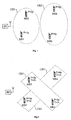
- Figure 1 shows mobile stations MS1-MS4 in the proximity of a base station BS. All of the mobile stations MS1-MS4 are assumed to be located within the area covered by the base station BS.
- a first mobile station MS1 indicates that its power requirement P from the base station BS is very low, let us say 1p (where p is a power unit, e.g. Watt, kilowatt or some corresponding unit).
- a second mobile station MS2 indicates with a power parameter value of 5p that it requires a relatively high output power from the base station BS.
- a third mobile station MS3 and a fourth mobile station MS4 have a respective output power requirement or demand P of 2p and 6p from the base station BS.
- the base station BS must adapt the output power of each channel, i.e. the downlink, to that mobile station that at present receives information on the channel whose output power demand is highest. Consequently, if it is desired to minimize the total power transmitted from the base station BS, it is desirable to collect mobile stations that have a high output power demand on certain channels and mobile stations that have a lower output power demand on other channels. Seen generally, mobile stations that have similar output power demands should be allocated the same channel as far as possible. Such allocation can be achieved with the aid of a so-called cost function, which for each combination of mobile stations on the available channels delivers a cost value ⁇ (P) that indicates the level of favourability of the combination concerned from an output power aspect.
- first mobile station MS1 and the third mobile station MS3 should be assigned to the first channel CH1
- second mobile station MS2 and the fourth mobile station MS4 should be assigned to the second channel CH2 (or vice versa) as illustrated in Figure 1.
- FIG. 2 shows mobile stations MS1-MS4 which are all positioned within the coverage area of a given base station BS.
- the first mobile station MS1 and the fourth mobile station MS4 will preferably be assigned to the first channel CH1 and the second mobile station MS2 and the third mobile station MS3 assigned to the second channel CH2, or vice versa.
- Figure 2 illustrates this assignment of the mobile stations MS1-MS4.
- Figure 3 shows mobile stations MS1-MS4 located within the coverage range of a base station BS.
- the base station BS is equipped with at least one adaptive antenna 310-340, i.e. a directional sensitive antenna by means of which the base station BS is able to determine which configuration of the angular power spectrum A is relevant to mobile stations in the vicinity of the base station BS or at least in which directional bearing A relative to the base station BS a given mobile station is positioned.
- the base station BS is equipped with at least one adaptive antenna 310-340, i.e. a directional sensitive antenna by means of which the base station BS is able to determine which configuration of the angular power spectrum A is relevant to mobile stations in the vicinity of the base station BS or at least in which directional bearing A relative to the base station BS a given mobile station is positioned.
- a first mobile station MS1 positioned within a first sector a 1 of a first adaptive antenna 310 of the base station BS has an output power demand P from the base station BS of 1p, and an effective transmission time span T of 1t.
- the cost value ⁇ (P,T,A) 5 ⁇ 5pt + 6 ⁇ 1pt + 2 ⁇ (5-1)pt 39pt is obtained.
- first and the second mobile stations MS1 and MS2 should preferably be assigned to the first channel CH1 and the third and fourth mobile stations MS3 and MS4 assigned to the second channel CH2, or vice versa.
- Figure 3 illustrates this assignment of the mobile stations MS1-MS4.
- the present invention provides an optimization that minimizes the energy that the base station is expected to transmit, on the basis of other available parameters. This optimization can be made by assuming that the effective transmission times will be of long duration and equally as long for all mobile stations. Minimization of energy transmitted from the base station will then be the same as minimizing the power transmitted from the base station and therewith minimizing the energy transmission.
- Figure 4 illustrates mobile stations MS1-MS4 in the vicinity of a base station BS. All of these stations MS1-MS4 are assumed to be positioned within the area covered by the base station BS.
- a first mobile station MS1 has a first angular power spectrum configuration by virtue of being located within a first sector a 1 of an angular power spectrum of an adaptive antenna 410 of the base station BS, and has an output power demand P from the base station BS of 1p.
- a second mobile station MS2 is located within the same sector a 1 and has an output power demand P of 5p from the base station BS.
- a third and a fourth mobile station MS3 and MS4 respectively are located within a second sector a 2 of the adaptive antenna 410 and have an output power demand P from the base station of 2p and 6p respectively.
- the first and the second mobile stations MS1 and MS2 should thus be assigned to the first channel CH1, and the third and the fourth mobile stations MS3 and MS4 should be assigned to the second channel CH2, or vice versa.
- Figure 5 illustrates mobile stations MSX1-MSX5 that are located within the coverage areas of base stations BSX1-BSX6 that are represented by cells C1-C6 adjacent to a cell C that corresponds to the coverage area of a given base station BS.
- Two mobile stations MSY1 and MSY2 are also located within the coverage area C of the base station BS, these mobile stations representing mobile stations MSY1, MSY2 that are expected to commence communication within the base station BS within a second time interval ⁇ 2 , with respect to the history of earlier call connections within the coverage area C.
- the assumption that such earlier unobserved mobile stations MSY1, MSY2 will either make an access request or receive a paging message within the second time period ⁇ 2 is based on call history, where it is assumed that new calls can be described as stochastic processes of Poisson distribution, for instance.
- Data relating to speed vectors v x1-5 , d x1-5 for possible future mobile stations MSX1-MSX5 can be obtained from Doppler shift measurements and/or extrapolation of time shift parameters (such as timing advance values, for instance) for those mobile stations MSX1-MSX5 that have been registered by base stations BSX1-BSX5 responsible for those adjacent cells in which the mobile stations MSX1-MSX5 are located at that moment.
- time shift parameters such as timing advance values, for instance
- ⁇ T MAX When a certain channel assignment delay ⁇ T MAX can be accepted, it is possible to further reduce the total energy transmitted from the base station. Naturally, the highest tolerated delay ⁇ T MAX may not exceed a value stipulated by the transmission priority of potential mobile stations.
- FIG. 6a is a diagrammatic illustration of how the first and fourth mobile stations MS1 and MS4 are assigned to a first channel CH1, wherewith a transmitted energy of 6pt is obtained (i.e. the area beneath maximum output power requirement).
- the total energy transmitted from the base station BS can be further reduced.
- a maximum of two mobile stations MSn k and MSm k can utilize the channel CH1 at each given moment in time, typically uplink and downlink respectively. It is therefore necessary for two of the mobile stations MS3 and MS1 to wait until information transmissions from the base station BS to the two remaining mobile stations MS1 and MS4 have been completed before commencing the transmission of information to the mobile stations MS1, MS3.
- the lowest total energy transmission from the base station BS is obtained when the channel CH1 is allocated initially to the second mobile station MS2 and to the fourth mobile station MS4.
- a further reduction in the energy transmitted from the base station can also be achieved when allowing the information transmissions from the base station to the mobile stations to be divided into smaller information units, for instance units in the size of data blocks.
- Such division is liable to result in the summated time for transmitting the divided information units will exceed the transmission time for the original arrangement of information.
- FIG. 8 is a flowchart illustrating one embodiment of the inventive method in which the total energy transmitted in sending information from a given base station BS to mobile stations MS in the vicinity of said base station is minimized.
- a check is made to ascertain whether or not mobile stations MS are located within the area covered by the base station BS. If mobile stations are found to be present, a timer is set to zero in the next step 810, otherwise step 800 is repeated until a mobile station MS is located within the coverage area of said base station BS.
- the timer is started in step 820, wherewith its time parameter begins to run and parameters P and/or T and/or A in respect of all mobile stations MS in the vicinity of the base station BS and which can be expected to communicate with the base station within a determined time ⁇ are registered by the base station BS in step 830. Parameters P, T and A for certain mobile stations MS in cells adjacent to the cell concerned are also registered. Cost values ⁇ 1 , ⁇ 2 , ..., ⁇ i for all i possible combinations of the mobile stations MS on the channels of the base station BS are calculated in step 840 in accordance with a cost function ⁇ (P,T,A).
- step 850 the mobile stations MS are assigned to the channels in accordance with the combination that gave the lowest cost value ⁇ min in the preceding step 840.
- step 860 the mobile stations MS are assigned to said channels by, e.g., USFs being sent from the base station BS.
- the procedure waits in the final step 870 until the time parameter of the timer has reached a determined value ⁇ , whereafter the procedure returns to step 800.
- a TDMA frame is comprised of eight time slots numbered from zero to seven. These time slots form eight so-called physical channels. A number of TDMA frames together form a multiframe. Multiframes are used in GSM as carriers of so-called logic channels, which may be used to transmit packet data, for instance. A certain such logic channel is comprised of a determined time slot in each TDMA frame on a separate carrier frequency. When data is transferred physically between a base station and a mobile station, each information block is divided into four data bursts of mutually equal size, each comprising 60 information bits, for instance. When the radio communications system is a TDMA system, the data bursts can be transmitted bit-interleaved in four consecutive time slots on a time-divided channel.
- Figure 9 illustrates the division of a logic channel CH1 of a base station divided into TDMA frames.
- the channel CH1 will be shared by three mobile stations MS1, MS2 and MS3 during a time span corresponding to the TDMA frames 1-32.
- a first mobile station MS1 and a third mobile station MS3 transmit information to the base station, while a second mobile station MS2 receives information from said base station.
- This information is assumed to be data that has been divided into information blocks.
- Each information block is assumed to occupy four consecutive TDMA frames and is designated DATA#(# tot ), where #(# tot ) denotes the ordinal number of the information block concerned and the total number of blocks in the transmission.
- a numerical prefix of an information block in uplink discloses the mobile station from which the block originates.
- 3DATA2(4) designates the second information block in a transmission of a total of four blocks from the mobile station MS3 to the base station.
- USF indicates the mobile station MS for which the uplink of the channel CH1 has been reserved in the next following four TDMA frames and specifies R(# MS ).
- R(1) means that the uplink of channel CH1 is used by the first mobile station MS1 during the following four TDMA frames.
- address information lies in the actual information block and consequently no flag corresponding to USF is required.
- the aforementioned effective transmission time T for transmitting information from a base station to a specific mobile station is thus proportional to the number of information blocks # tot included in the current transmission.
- the base station sends a USF that states R(1) that a first mobile station MS1 is authorized to send a first information block 1DATA1(3) in the next-following four TDMA frames 5-8 on the uplink of the channel CH1.
- the next USF which is sent during the TDMA frames 5-8, states that R(1) the first mobile station MS1 may send a second information block 1DATA2(3) during the next-following four TDMA frames 9-12.
- the first mobile station MS1 sends the first information block 1DATA1(3) at the same time.
- Information DATA1(4) is sent to the second mobile station MS2 on the downlink of the channel CH1 at the same time, and the first mobile station MS1 sends the second information block 1DATA2(3) on the downlink of the channel CH1.
- the USF sent during the TDMA frames 13-16 contains information to the effect that R(3) the third mobile station MS3 may begin to send information on the uplink of the channel CH1 in TDMA frame 17.
- the downlink information DATA2(4) during the TDMA frames 13-16 is also intended for the second mobile station MS2 and the first mobile station MS1 sends the third and the last information block 1DATA3(3) on the uplink.
- the content DATA3(4) of the TDMA frame 17-20 on the downlink is also intended for the second mobile station MS2.
- the base station sends a USF that shows that R(3) the uplink is at the disposal of the third mobile station MS3 during the TDMA frames 21-24 for transmission of a second information block 3DATA2(4).
- the third mobile station MS3 sends a first information block 3DATA1(4) parallel therewith.
- the downlink information DATA4(4) during the TDMA frames 21-24 is also addressed to the second mobile station MS2 and the USF transmitted during the TDMA frames 21-24 states that r(3) the third mobile station MS3 can send a further data block 3DATA3(4) during the TDMA frames 25-28.
- the third mobile station MS3 sends a second information block 3DATA2(4) at the same time.
- the downlink has no information content during the time of the TDMA frames 25-28 (i.e. the downlink contains only dummy bits sent form the base station on the channel CH1) and the third mobile station MS3 sends a third information block 3DATA3(4).
- USF indicates in the TDMA frames 25-28 that R(3) the third mobile station MS3 may send a last information block 3DATA4(4) during the TDMA frames 29-32, while the downlink of the channel CH1 is still empty.
- the terminating information block 3DATA4(4) is sent by the third mobile station MS3 during these TDMA frames 25-28.
- FIG 10 illustrates an embodiment of the inventive arrangement.
- a control unit 1030 receives from a base station 1000 information relating to output power demand P, effective transmission times T and the relevant configuration of the angular power spectrum A for mobile stations in its vicinity.
- the control unit 1030 is included in a transceiver unit 1010 in the base station 1000, since the received parameters P, T and A are found available in the transceiver unit 1010.
- Information concerning the relevant configuration of the angular power spectrum A of the mobile stations may conveniently be obtained with the aid of an adaptive antenna. 1020.
- the processor unit 1040 then generates USFs for the channels CH1-CHm in accordance with the channel allocation.
- a timer unit 1070 delivers a first signal U which causes the processor unit 1040 to perform a new collection of parameter values P, T and/or A and a new assignment of mobile stations MS1-MSn to the base station channels CH1-CHm.
- the processor unit 840 sets the timer unit 1070 to zero via a second signal R, wherewith the time parameter of the time unit 870 begins again to run.
Abstract
Description
- The present invention relates to a method of assigning mobile stations to radio channels in a mobile radio communications system. The radio channels are assumed to be so-called multi-user channels, in other words a plurality of mobile stations may simultaneously share a channel over a given period of time.
- The invention also relates to a base station arranged for assigning multi-user channels to mobile stations in accordance with said method.
- In conventional radio communications systems for telephony, each unit is assigned its own channel with separate uplink and downlink. A given channel, represented for instance by a given time slot on a special carrier frequency, of a given base station cannot be assigned to a new mobile station before an earlier call connection on the channel has been released.
- In the case of single-path non-selected transmission within the radio communications system, so-called broadcasting, a pool of available channels is utilized for transmitting messages with several simultaneous receivers. Many different algorithms for determining which of the available channels is most suitable for distributing this type of message have earlier been described.
- U.S. Patent Specification US-A 5,530,917 teaches a method of optimizing channel utilization within a mobile telephony system. According to this method, channel assignment is effected on the basis of calculated load factors that have been obtained from at least two alternative sets of parameter values. The parameters include both radio-specific characteristics and other characteristics relevant to the call setup concerned. The method is applied both when changing channels for a call connection that has already been established and with handover.
- International Patent Application WO-A1 96/07287 teaches a method of assigning carrier frequencies and time slots to mobile stations in a radio communications system of the TDMA/FDMA hybrid type (TDMA = Time Division Multiple Access. FDMA = Frequency Division Multiple Access). Mobile stations are assigned time slots on carrier frequencies such that mobile stations having roughly the same power output demand from the base station will be given the same carrier frequency. In consequence, the output power for each carrier frequency utilized is minimized and the available frequency band is used as effectively as.possible. Interference in the radio communications system is also reduced.
- International Patent Application WO-A1 95/07012 teaches a method in which base stations that encounter interference problems on certain of their channels are collected in a database. The base stations in the database are controlled to lower the output power on the channels concerned to a lowest value acceptable for the mobile stations that use these channels. An effort is thus made to constantly keep the number of base stations in the database as small as possible, therewith leading to a reduction in the interference in the radio communications system as a whole.
- The service GPRS within GSM enables several mobile stations to use the same channel simultaneously for the transmission of information between a given base station and the mobile stations that are connected thereto (GPRS = General Packet Radio Service; GSM = Global System for Mobile communication). Each channel includes an uplink for the transmission of information from the mobile station to the base station, and a downlink for the transmission of information from the base station to the mobile station. The simultaneous use of a channel will mean that two or more mobile stations transmit and receive information on the channel in parallel, or that two or more mobile stations use the channel alternately over a given time period either to send information to a base station or to receive information from a base station. The downlink of a channel can be used typically to transmit information to a first mobile station at the same time as a second mobile station transmits on the uplink of the channel.
- The information transmitted consists typically of data packets that are divided into information blocks of specific size. By reading a USF, different mobile stations of a limited number of stations can receive different information from one and the same information block, which is transmitted via a common physical channel (USF = Uplink State Flag). A USF, which is transmitted in the payload on the downlink of a channel and read by all mobile stations that use a specific channel, indicates to which mobile station the next-arriving information block is addressed and which mobile station may transmit information on the channel uplink in the next-arriving time slot.
- GPRS pays no attention to individual communication parameters of the mobile stations when assigning a channel that is common to two or more mobile stations. The mobile station that has the highest output power requirement from the base station determines the output power level from the base station on the channel concerned. If the mobile station or the other mobile stations that share the channel places/place considerably lower output power demands on the base station, the base station will transmit with an output power that falls markedly below the minimum output power required, at least for some of the time. When mobile stations that are located on very different directional bearings, as seen from the base station, are assigned the same channel, there are essentially three different ways of making the channel available to all of these mobile stations at one and the same time. (1) A separate antenna lobe may be aimed at each mobile station; (2) an angular power spectrum that is based on information concerning both the directional bearing to the mobile station and the propagation conditions for the radio waves between the base station and the mobile station may be generated for each mobile station, and; (3) there may be used an antenna lobe that is sufficiently wide to cover all mobile stations. In all of these cases, and particularly in the latter case, electromagnetic energy will be transmitted over a wider geographical area than is necessary in order to send information from the base station to the mobile stations.
- In the method described inWO-A1 95/07012, the power on channels that have already been assigned is minimized. However, the method does not address how the assignment of mobile stations to the base stations should be carried out with the view of avoiding interference in a radio communications system.
- The method taught by WO-A1 96/07287 results in mobile stations that have similar output power demands being assigned different channels on the same carrier frequency.
- However, the method provides no solution to the problem of how a channel should be assigned to several simultaneous users of the channel. Furthermore, no account is taken of how the mobile stations are orientated in relation to the base station or to the length of time over which the mobile stations ask for channel capacity. Neither is this taken into account when optimizing channel usage as disclosed in
US-A 5.530,917. - The present invention provides a solution to the problem of optimally assigning several simultaneous mobile stations to the channels of a base station. By optimal assignment is meant here an assignment in which the total energy transmitted in sending information from the base station to all mobile stations within its radio coverage area is minimized. One link in minimizing the energy transmitted may, for instance, be achieved by minimizing the output power on each channel from the base station.
- Thus, one object of the present invention is to reduce the total interference in a radio communications system.
- Another object of the invention is to optimize the extent to which the channels of a base station are utilized with respect to current communication requirements and to predicted future communications requirements.
- The invention is effective in minimizing the total energy transmitted from base stations when sending information to associated mobile stations. Since the energy transmitted is equivalent to the sum of the output power during the effective transmission time span, the average electromagnetic power transmitted will be minimized and the total interference in the radio communications system therewith also reduced. This enables each available channel in the system to be utilized in the most effective manner possible, which, in turn, imparts a high degree of efficiency to the radio communications system as a whole.
-
- Figure 1 shows how mobile stations in the vicinity of a base station are allocated channels from its list of channels in accordance with the value of a power parameter.
- Figure 2 shows how mobile stations in the vicinity of a base station are allocated channels from its list of channels in accordance with the value of a power parameter and a time parameter.
- Figure 3 shows how mobile stations in the vicinity of a base station are allocated channels from its list of channels in accordance with the value of a power parameter, a time parameter and an angular parameter.
- Figure 4 shows how mobile stations in the vicinity of a base station are allocated channels from its list of channels in accordance with the value of a power parameter and an angular parameter.
- Figure 5 illustrates movement of mobile stations in a cell structure within a radio communications system.
- Figure 6a, b are diagrammatic illustrations of how mobile stations are allocated a first and a second channel respectively.
- Figure 7 is a diagrammatic illustration of how the mobile stations in Figures 6a and 6b are allocated one and the same channel.
- Figure 8 is a flowchart illustrating one embodiment of the inventive method.
- Figure 9 is a graphic illustration of how three mobile stations share a logic channel during a given time span.
- Figure 10 illustrates an embodiment of the inventive arrangement.
-
- The invention will now be describe din more detail with reference to preferred embodiments thereof and with reference to the accompanying drawings.
- Figure 1 shows mobile stations MS1-MS4 in the proximity of a base station BS. All of the mobile stations MS1-MS4 are assumed to be located within the area covered by the base station BS. A first mobile station MS1 indicates that its power requirement P from the base station BS is very low, let us say 1p (where p is a power unit, e.g. Watt, kilowatt or some corresponding unit). A second mobile station MS2 indicates with a power parameter value of 5p that it requires a relatively high output power from the base station BS. A third mobile station MS3 and a fourth mobile station MS4 have a respective output power requirement or demand P of 2p and 6p from the base station BS.
- The base station BS must adapt the output power of each channel, i.e. the downlink, to that mobile station that at present receives information on the channel whose output power demand is highest. Consequently, if it is desired to minimize the total power transmitted from the base station BS, it is desirable to collect mobile stations that have a high output power demand on certain channels and mobile stations that have a lower output power demand on other channels. Seen generally, mobile stations that have similar output power demands should be allocated the same channel as far as possible. Such allocation can be achieved with the aid of a so-called cost function, which for each combination of mobile stations on the available channels delivers a cost value Ψ(P) that indicates the level of favourability of the combination concerned from an output power aspect. Providing that the number of mobile stations MS1-MS4 is an even number 2N, that two mobile stations MSnk and MSmk are assigned to each channel, and that the output power demand P of a given mobile station is channel-independent, thenwhere
 where
where
IF Pnk ≥ Pmk THEN Pnk , mk = Pnk
ELSE Pnk , mk = Pmk
a cost function that gives the cost values Ψ(P) for combinations of mobile stations MSnk and MSmk that have a Pnk and Pmk respectively and where Pnk , mk is the output power required to transmit information to the mobile stations MSnk and MSmk. - When the first mobile station MS1 and the second mobile station MS2 are assigned to a first channel CH1, and the third mobile station MS3 and the fourth mobile station MS4 are assigned to a second channel CH2, the cost value Ψ(P) = 5p + 6p = 11p is obtained.
- On the other hand, if the first mobile station MS1 and the third mobile station MS3 are assigned to the first channel CH1 and the second mobile station MS2 and the fourth mobile station MS4 are assigned to the second channel CH2, the corresponding cost value Ψ(P) = 2p + 6p = 8p.
- The cost value for the remaining combination of the first mobile station MS1 and the fourth mobile station MS4 on the first channel CH1 and the second mobile station MS2 and the third mobile station MS3 on the second channel CH2 will be Ψ(P) = 6p + 5p = 11p.
- Thus, the first mobile station MS1 and the third mobile station MS3 should be assigned to the first channel CH1, and the second mobile station MS2 and the fourth mobile station MS4 should be assigned to the second channel CH2 (or vice versa) as illustrated in Figure 1.
- Figure 2 shows mobile stations MS1-MS4 which are all positioned within the coverage area of a given base station BS. A first mobile station MS1 indicates an output power requirement P from the base station BS of P = 1p. It also indicates that the effective time span T for transmission of information from the base station BS to the first mobile station MS1 is T = 1t (where t is a time unit, such as seconds, milliseconds or some like time unit). Corresponding parameters for a second mobile station MS2 are P = 5p and T = 5t, for a third mobile station MS3 P = 2p and T = 5t, and for a fourth mobile station MS4 P = 6p and T = 1t.
- Since the time span during which power is transmitted from the base station BS is decisive for the magnitude of the total energy transmitted, it is desirable to minimize the combined products between the output power demand P and effective transmission time T of respective mobile stations MS1-MS4.
- Provided that the number of mobile stations MS1-MS4 is an even number 2N, that two mobile stations MSnk and MSmk are assigned to each channel, and that the output power demand P of a given mobile station is channel-independent, a cost function that takes into account the output power demand P of the mobile stations MS1-MS4 and also the effective transmission times T is:where
 where
where
IF Pnk ≥ Pmk THEN
IF Tnk ≥ Tmk THEN Wnk , mk = Pnk ·Tnk
ELSE Wnk , mk = Pnk ·Tnk + Pmk ·(Tmk - Tnk )
ELSE
IF Tmk ≥ Tnk THEN Wnk , mk = Pmk ·Tmk
ELSE Wnk , mk = Pmk ·Tmk + Pnk ·(Tnk - Tmk )
which gives the cost values Ψ(P,T) for combinations of mobile stations MSnk and MSmk with output power demands of Pnk and Pmk respectively, effective transmission times Tnk and Tmk and where Wnk , mk is the energy required to send information to the mobile stations MSnk and MSmk. - When the first mobile station MS1 and the second mobile station MS2 are assigned to a first channel CH1, and a third mobile station and the fourth mobile station MS4 are assigned to a second channel CH2, the cost value Ψ(P,T) = 5·5pt + 6·1pt + 2·(5-1)pt = 39pt.
- When the first mobile station MS1 and the third mobile station MS3 are assigned to the first channel CH1 and the second mobile station and the fourth mobile station MS4 are assigned to the second channel CH2, the corresponding cost value is Ψ(P,T) = 2· 5pt + 6·1pt + 5·(5-1)pt = 36pt.
- When the first mobile station MS1 and the fourth mobile station MS4 are, instead, assigned to the first channel CH1 and the second mobile station MS2 and the third mobile station MS3 are assigned to the second channel CH2, the cost value is Ψ(P,T) = 6·1pt + 5·5pt = 31pt.
- Consequently, the first mobile station MS1 and the fourth mobile station MS4 will preferably be assigned to the first channel CH1 and the second mobile station MS2 and the third mobile station MS3 assigned to the second channel CH2, or vice versa. Figure 2 illustrates this assignment of the mobile stations MS1-MS4.
- In addition to assigning mobile stations MS1-MS4 that have similar output power demands P to the same channel as far as is possible, or to assign to the same channel mobile stations MS1-MS4 whose products between output power demands P and effective transmission times T are the same, it is also suitable to assign to the same channel those mobile stations MS1-MS4 whose directional bearing A is approximately the same with respect to the base station BS. When mobile stations that are located on essentially different directional bearings are assigned to the same channel, it is necessary for the base station BS either to use simultaneously several completely different angular power spectrums in transmission, or there must be used an antenna lobe which is sufficiently wide to cover all mobile stations. In both of these cases, electromagnetic energy will be transmitted over a wider geographical area than is necessary for transmitting information from the base station BS to the mobile stations MS1-MS4.
- Figure 3 shows mobile stations MS1-MS4 located within the coverage range of a base station BS. In the illustrated case, the base station BS is equipped with at least one adaptive antenna 310-340, i.e. a directional sensitive antenna by means of which the base station BS is able to determine which configuration of the angular power spectrum A is relevant to mobile stations in the vicinity of the base station BS or at least in which directional bearing A relative to the base station BS a given mobile station is positioned.
- A first mobile station MS1 positioned within a first sector a1 of a first
adaptive antenna 310 of the base station BS has an output power demand P from the base station BS of 1p, and an effective transmission time span T of 1t. Corresponding parameters A = a1, P = tp and T = 5t for a second mobile station MS2, A = a2, P = 2p and T = 5t for a third mobile station MS3, and A = a2, P = 6p and T = 1t for a fourth mobile station MS4. - A cost function that takes into account the relevant configuration of the angular power spectrum A of the base station BS for the mobile stations MS1-MS4, the output power demand P of the mobile stations MS1-MS4, and effective transmission time spans T, provided that the number of mobile stations MS1-MS4 is an even number 2N, that two mobile stations MSnk and MSmk are assigned to each channel, and that the power output demand P of a given mobile station is channel-independent, iswhere
 where IF (MSnk and MSmk are positioned within the same sector ai) THEN
IF Pnk ≥ Pmk THEN
IF Tnk ≥ Tmk THEN Wnk , mk = Pnk ·Tnk
ELSE Wnk , mk = Pnk ·Tnk + Pmk ·(Tmk - Tnk )
ELSE
IF Tmk ≥ Tnk THEN Wnk , mk = Pmk ·Tmk
ELSE Wnk , mk = Pmk ·Tmk + Pnk ·(Tnk - Tmk )
ELSE Wnk , mk = Pnk ·Tnk + Pmk ·Tmk
which gives the cost values Ψ(P,T,A) combinations of mobile stations MSnk and MSmk that either have the same configuration of angular power spectrum (typically located in the same sector A = ai of the angular power spectrum of the base station BS) or have different configurations of angular power spectrum (typically located in different sectors A = ai of the angular power spectrum of the base station BS), have respective output power demands of Pnk and Pmk , respective effective transmission times of Tnk and Tmk and where Wnk , mk is the energy required to send information to the mobile stations MSnk and MSmk. - When the first mobile station MS1 and the second mobile station MS2 are assigned to a first channel CH1 and the third mobile station MS3 and the fourth mobile station MS4 are assigned to a second channel CH2, the cost value Ψ(P,T,A) 5·5pt + 6·1pt + 2·(5-1)pt = 39pt is obtained.
- On the other hand, when the first and third mobile stations MS1 and MS3 are assigned to the first channel CH1 and the second and the fourth mobile stations MS2 and MS4 are assigned to the second channel CH2, the corresponding cost value is Ψ(P,T,A) = 1·1pt + 6·1pt + 5·5pt + 2·5pt = 42pt.
- Finally, when the first and fourth mobile stations MS1 and MS4 are assigned to the first channel CH1 and the second and the third mobile stations MS2 and MS3 are assigned to the second channel CH2, the cost value is Ψ(P,T,A) = 1.1pt + 6·1pt + 5·5pt + 2·5pt = 42 pt.
- Thus, the first and the second mobile stations MS1 and MS2 should preferably be assigned to the first channel CH1 and the third and fourth mobile stations MS3 and MS4 assigned to the second channel CH2, or vice versa. Figure 3 illustrates this assignment of the mobile stations MS1-MS4.
- When the effective transmission time spans for the information that will be transmitted from a given base station to mobile stations within its coverage area are not known, the present invention provides an optimization that minimizes the energy that the base station is expected to transmit, on the basis of other available parameters. This optimization can be made by assuming that the effective transmission times will be of long duration and equally as long for all mobile stations. Minimization of energy transmitted from the base station will then be the same as minimizing the power transmitted from the base station and therewith minimizing the energy transmission.
- Figure 4 illustrates mobile stations MS1-MS4 in the vicinity of a base station BS. All of these stations MS1-MS4 are assumed to be positioned within the area covered by the base station BS.
- A first mobile station MS1 has a first angular power spectrum configuration by virtue of being located within a first sector a1 of an angular power spectrum of an
adaptive antenna 410 of the base station BS, and has an output power demand P from the base station BS of 1p. A second mobile station MS2 is located within the same sector a1 and has an output power demand P of 5p from the base station BS. A third and a fourth mobile station MS3 and MS4 respectively are located within a second sector a2 of theadaptive antenna 410 and have an output power demand P from the base station of 2p and 6p respectively. - Provided that the number of mobile stations MS1-MS2 is an even number 2N, and that two mobile stations MSnk and MSmk are assigned to each channel, and that the output power demand P for a given mobile station is channel-independent, a cost function that takes into account the relevant configuration of the angular power spectrum A of the base station BS for the mobile stations MS1-MS4 and the output power demand B of the mobile stations MS1-MS4 will bewhere
 where IF (MSnK MSmK are positioned within the same sector ai)
THEN IF Pnk ≥ Pmk THEN Pnk , mk = Pnk
ELSE Pnk , mk = Pmk
ELSE Pnk , mk = Pnk + Pmk
which gives the cost values Ψ(P,A) for combinations of mobile stations MSnk and MSmk that either have the same angular power spectrum configuration A = ai (typically located in the same sector) or different angular power spectrum configurations A = ai (typically located in different sectors), have respective output power demands of Pnk and Pmk and where Pnk , mk is the power transmitted when sending information to the mobile stations MSnk and MSmk. - When the first and the second mobile stations MS1 and MS2 are assigned to a first channel CH1 and the third and the fourth mobile stations MS3 and MS4 are assigned to a second channel CH3, the cost value Ψ(P,A) = 5p + 6p = 11p is obtained.
- When the first and the third mobile stations MS1 and MS3 are assigned to the first channel CH1 instead, and the second and the fourth mobile stations MS2 and MS4 are assigned to the second channel CH2, the corresponding cost value is Ψ(P,A) = 1p + 2p + 5p + 6p = 14p.
- The cost value will be Ψ(P,A) = 1p + 6p + 5p + 2p = 14p for the remaining combination of the first and the fourth mobile stations MS1 and MS4 assigned to the first channel CH1 and the second and third mobile stations MS2 and MS3 assigned to the second channel CH2.
- The first and the second mobile stations MS1 and MS2 should thus be assigned to the first channel CH1, and the third and the fourth mobile stations MS3 and MS4 should be assigned to the second channel CH2, or vice versa.
- When wishing to optimize assignment of mobile stations to the available channels of a base station over a first time interval τ1, rather than instantaneously, from an energy aspect, it is also necessary to into account those mobile stations that are correctly located within the area covered by adjacent base stations but which are expected to communicate with the base station concerned within the first time interval τ1. Figure 5 illustrates mobile stations MSX1-MSX5 that are located within the coverage areas of base stations BSX1-BSX6 that are represented by cells C1-C6 adjacent to a cell C that corresponds to the coverage area of a given base station BS. Two mobile stations MSY1 and MSY2 are also located within the coverage area C of the base station BS, these mobile stations representing mobile stations MSY1, MSY2 that are expected to commence communication within the base station BS within a second time interval τ2, with respect to the history of earlier call connections within the coverage area C. The assumption that such earlier unobserved mobile stations MSY1, MSY2 will either make an access request or receive a paging message within the second time period τ2 is based on call history, where it is assumed that new calls can be described as stochastic processes of Poisson distribution, for instance.
- Thus, when calculating the aforesaid cost functions Ψ for the base station BS, parameters P and/or T and/or A for those mobile stations MSX1-MSX3 and MSY1, MSY2 respectively are included, these mobile stations either having a speed vx1, vx2, vx3 and a direction dx1, dx2, dx3 which suggests that they can be expected to exchange information with the base station BS or, on probable grounds, can be expected to commence an exchange of information with the base station BS within a given time interval τ. Data relating to speed vectors vx1-5, dx1-5 for possible future mobile stations MSX1-MSX5 can be obtained from Doppler shift measurements and/or extrapolation of time shift parameters (such as timing advance values, for instance) for those mobile stations MSX1-MSX5 that have been registered by base stations BSX1-BSX5 responsible for those adjacent cells in which the mobile stations MSX1-MSX5 are located at that moment.
- All cost functions Ψ(P), Ψ(P,T), Ψ(P,T,A) and Ψ(P,A) described with reference to Figures 1, 2, 3 and 4 respectively presume that the transfer of information from the base station BS to the mobile stations MS1-MS4 has commenced immediately, i.e. without delay.
- When a certain channel assignment delay ΔTMAX can be accepted, it is possible to further reduce the total energy transmitted from the base station. Naturally, the highest tolerated delay ΔTMAX may not exceed a value stipulated by the transmission priority of potential mobile stations.
- For instance, the total energy transmitted from the base station BS in the example described with reference to Figure 2 above could be reduced from Ψ(P,T) = 31pt to Ψ(P,T) = 28pt if a maximum delay ΔTMAX = 5T could be accepted. Figure 6a is a diagrammatic illustration of how the first and fourth mobile stations MS1 and MS4 are assigned to a first channel CH1, wherewith a transmitted energy of 6pt is obtained (i.e. the area beneath maximum output power requirement). Figure 6b is a corresponding diagrammatic illustration of how the second and the third mobile stations MS2 and MS3 are assigned to a second channel CH2, therewith obtaining a transmitted energy of 25pt. All transmissions are commenced immediately at time T = 0t and take place in parallel. The total energy transmitted is Ψ(P,T) = 6pt + 25pt = 31pt.
- When all mobile stations MS1-MS4 are assigned to one and the same channel CH1, the total energy transmitted from the base station BS can be further reduced. We still assume that a maximum of two mobile stations MSnk and MSmk can utilize the channel CH1 at each given moment in time, typically uplink and downlink respectively. It is therefore necessary for two of the mobile stations MS3 and MS1 to wait until information transmissions from the base station BS to the two remaining mobile stations MS1 and MS4 have been completed before commencing the transmission of information to the mobile stations MS1, MS3. The lowest total energy transmission from the base station BS is obtained when the channel CH1 is allocated initially to the second mobile station MS2 and to the fourth mobile station MS4. The channel CH1 is allotted to the third mobile station MS3 at time T = 1t, and to the first mobile station MS1 at the time T = 5t. The third mobile station MS3 is thus delayed by ΔTMS3 = 1t and a corresponding delay in respect of the first mobile station MS1 is ΔTMS1 = 5t. This circumstance is illustrated in Figure 7, from which it will also be apparent that the total energy transmitted from the base station BS will be Ψ(P,T) = 6·1pt + 5·(5-1)pt 2·(6-5)pt = 28pt.
- A further reduction in the energy transmitted from the base station can also be achieved when allowing the information transmissions from the base station to the mobile stations to be divided into smaller information units, for instance units in the size of data blocks. However, such division is liable to result in the summated time for transmitting the divided information units will exceed the transmission time for the original arrangement of information.
- Figure 8 is a flowchart illustrating one embodiment of the inventive method in which the total energy transmitted in sending information from a given base station BS to mobile stations MS in the vicinity of said base station is minimized. In a
first step 800, a check is made to ascertain whether or not mobile stations MS are located within the area covered by the base station BS. If mobile stations are found to be present, a timer is set to zero in thenext step 810, otherwise step 800 is repeated until a mobile station MS is located within the coverage area of said base station BS. The timer is started instep 820, wherewith its time parameter begins to run and parameters P and/or T and/or A in respect of all mobile stations MS in the vicinity of the base station BS and which can be expected to communicate with the base station within a determined time τ are registered by the base station BS instep 830. Parameters P, T and A for certain mobile stations MS in cells adjacent to the cell concerned are also registered. Cost values Ψ1, Ψ2, ..., Ψi for all i possible combinations of the mobile stations MS on the channels of the base station BS are calculated instep 840 in accordance with a cost function Ψ(P,T,A). In thenext step 850, the mobile stations MS are assigned to the channels in accordance with the combination that gave the lowest cost value Ψmin in the precedingstep 840. Instep 860, the mobile stations MS are assigned to said channels by, e.g., USFs being sent from the base station BS. The procedure waits in thefinal step 870 until the time parameter of the timer has reached a determined value τ, whereafter the procedure returns to step 800. - In GSM, a TDMA frame is comprised of eight time slots numbered from zero to seven. These time slots form eight so-called physical channels. A number of TDMA frames together form a multiframe. Multiframes are used in GSM as carriers of so-called logic channels, which may be used to transmit packet data, for instance. A certain such logic channel is comprised of a determined time slot in each TDMA frame on a separate carrier frequency. When data is transferred physically between a base station and a mobile station, each information block is divided into four data bursts of mutually equal size, each comprising 60 information bits, for instance. When the radio communications system is a TDMA system, the data bursts can be transmitted bit-interleaved in four consecutive time slots on a time-divided channel.
- Figure 9 illustrates the division of a logic channel CH1 of a base station divided into TDMA frames. In the illustrated example, the channel CH1 will be shared by three mobile stations MS1, MS2 and MS3 during a time span corresponding to the TDMA frames 1-32.
- A first mobile station MS1 and a third mobile station MS3 transmit information to the base station, while a second mobile station MS2 receives information from said base station.
- This information is assumed to be data that has been divided into information blocks. Each information block is assumed to occupy four consecutive TDMA frames and is designated DATA#(#tot), where #(#tot) denotes the ordinal number of the information block concerned and the total number of blocks in the transmission. A numerical prefix of an information block in uplink discloses the mobile station from which the block originates. Thus, 3DATA2(4) designates the second information block in a transmission of a total of four blocks from the mobile station MS3 to the base station. USF indicates the mobile station MS for which the uplink of the channel CH1 has been reserved in the next following four TDMA frames and specifies R(#MS). Thus, R(1) means that the uplink of channel CH1 is used by the first mobile station MS1 during the following four TDMA frames. When transmitting in the downlink, i.e. when transmitting information from the base station to a mobile station, address information lies in the actual information block and consequently no flag corresponding to USF is required.
- Naturally, information can be divided in other ways. Similarly, corresponding frame division can be effected in a CDMA system or an FDMA system.
- The aforementioned effective transmission time T for transmitting information from a base station to a specific mobile station is thus proportional to the number of information blocks #tot included in the current transmission. In the described TDMA example, the effective transmission time T is determined as T = 4· (the time of a data burst) #tot.
- In the initial TDMA frames 1-4, the base station sends a USF that states R(1) that a first mobile station MS1 is authorized to send a first information block 1DATA1(3) in the next-following four TDMA frames 5-8 on the uplink of the channel CH1. The next USF, which is sent during the TDMA frames 5-8, states that R(1) the first mobile station MS1 may send a second information block 1DATA2(3) during the next-following four TDMA frames 9-12. The first mobile station MS1 sends the first information block 1DATA1(3) at the same time. During the TDMA frames 9-12, there is sent a USF that indicates that R(1) the first mobile station MS1 may continue to send information 1DATA3(3). Information DATA1(4) is sent to the second mobile station MS2 on the downlink of the channel CH1 at the same time, and the first mobile station MS1 sends the second information block 1DATA2(3) on the downlink of the channel CH1. The USF sent during the TDMA frames 13-16 contains information to the effect that R(3) the third mobile station MS3 may begin to send information on the uplink of the channel CH1 in TDMA frame 17. The downlink information DATA2(4) during the TDMA frames 13-16 is also intended for the second mobile station MS2 and the first mobile station MS1 sends the third and the last information block 1DATA3(3) on the uplink. The content DATA3(4) of the TDMA frame 17-20 on the downlink is also intended for the second mobile station MS2. During these TDMA frames 17-20, the base station sends a USF that shows that R(3) the uplink is at the disposal of the third mobile station MS3 during the TDMA frames 21-24 for transmission of a second information block 3DATA2(4). The third mobile station MS3 sends a first information block 3DATA1(4) parallel therewith. The downlink information DATA4(4) during the TDMA frames 21-24 is also addressed to the second mobile station MS2 and the USF transmitted during the TDMA frames 21-24 states that r(3) the third mobile station MS3 can send a further data block 3DATA3(4) during the TDMA frames 25-28. The third mobile station MS3 sends a second information block 3DATA2(4) at the same time. The downlink has no information content during the time of the TDMA frames 25-28 (i.e. the downlink contains only dummy bits sent form the base station on the channel CH1) and the third mobile station MS3 sends a third information block 3DATA3(4). USF indicates in the TDMA frames 25-28 that R(3) the third mobile station MS3 may send a last information block 3DATA4(4) during the TDMA frames 29-32, while the downlink of the channel CH1 is still empty. The terminating information block 3DATA4(4) is sent by the third mobile station MS3 during these TDMA frames 25-28.
- Figure 10 illustrates an embodiment of the inventive arrangement. A
control unit 1030 receives from abase station 1000 information relating to output power demand P, effective transmission times T and the relevant configuration of the angular power spectrum A for mobile stations in its vicinity. In the illustrated case, thecontrol unit 1030 is included in atransceiver unit 1010 in thebase station 1000, since the received parameters P, T and A are found available in thetransceiver unit 1010. However, it is quite feasible to place the control unit in any other desired position within or outside thebase station 1000. Information concerning the relevant configuration of the angular power spectrum A of the mobile stations may conveniently be obtained with the aid of an adaptive antenna. 1020. However, the information A can be generated in accordance with alternative methods with the aid of, e.g., GPS receivers in the mobile stations (GPS = Global Positioning System). - The parameter values MSi(P,T,A) for the mobile stations MS1-MSn, where i=1,...,n in the vicinity of the
base station 1000 are transferred from aprocessor unit 1040 in thecontrol unit 1030 and stored in afirst storage unit 1050. When the parameter values (MSi(P,T,A) for all mobile stations MS1-MSn have been registered in thefirst storage unit 1050, theprocessor unit 1040 distributes the mobile stations MS1-MSn over the available channels CH1-CHm in thebase station 1000 in accordance with the proposed method, assigns each mobile station to a channel CHj(MSi), where j=1,...,m; i=1,...n and stores the result in asecond storage unit 1060 which may, of course, also consist of a second partition of thefirst storage unit 1050. Theprocessor unit 1040 then generates USFs for the channels CH1-CHm in accordance with the channel allocation. When a predetermined time τ has passed since the last registration of the parameter values MSi(P,T,A) for the mobile stations MS1-MSn, atimer unit 1070 delivers a first signal U which causes theprocessor unit 1040 to perform a new collection of parameter values P, T and/or A and a new assignment of mobile stations MS1-MSn to the base station channels CH1-CHm. After having received the first signal U, theprocessor unit 840 sets thetimer unit 1070 to zero via a second signal R, wherewith the time parameter of thetime unit 870 begins again to run.
Claims (26)
- A method of assigning a plurality of mobile stations to multi-user channels for transmission of packet data in a mobile radio communications system, wherein the mobile stations are assigned to channels to enable communication of packet data between a base station (BS) and the mobile stations (MS1-MS4),
characterized in that the method comprising the steps of:selecting which mobile stations (MS1-MS4) to assign to which channels (CH1, CH2) based on a cost function (Ψ);deriving said cost function (Ψ) by taking in account a set of parameters (P;P,T;P,T,A;P,A) associated with respective mobile stations, and by choosing a first combination of at least two mobile (MS1,MS4) stations that simultaneously share a first channel (CH1,1t) in parallel to transmit and receive with the base station (BS), and at least a second combination of at least two mobile (MS2,MS3) stations that simultaneously share a second channel (CH2,1t-5t) in parallel to transmit and receive with the base station (BS), wherein the combination chosen of said mobile stations (MS1-MS4) on first or second channel (CH1-CH2) is the first and second combination that delivers a cost value (Ψ(P)) that allows for minimization of the total energy (P) transmitted from the base station (BS) in the transmission of packet data from said base station (BS) to said mobile stations (MS1-MS4). - A method according to Claim 1,
wherein said parameters (P;P,T;P,T,A;P,A) include a first time interval (τ1) and also the parameter values (1 p, 1t, a1 and 5p, 5t, a1 respectively) for a first set of mobile stations (MS1, MS2) which will commence communication with the base station (BS) within said first time interval (τ1), and the parameter values (2p, 5t, a2; 6p, 1t, a2) for a second set of mobile stations which are already in communication with the base station(BS); and
in that said assignment of mobile stations (MS1-MS4) takes place within said first and said second set. - A method according to Claim 1 or Claim 2,
wherein predicting the future presence of mobile stations (MSX1-MSX3) within the coverage area (C) of the base station (BS), this prediction being based on information relating to the speed (vx1-vx3) and the direction of movement (dx1-dx3) of mobile stations (MSX1-MSX5) that are in communication with base stations (BS1-BS6) whose respective coverage areas (C1-C6) are adjacent to the coverage area (C) of said base station (BS). - A method according to Claim 1 or Claim 2,
wherein predicting the future presence mobile stations (MSX1-MSX3) within the coverage area (C) of said base station (BS), said prediction being based on information relating to the position and the change in measured power from mobile stations (MSX1-MSX5) that are in communication with base stations (BS1-BS6) whose respective coverage areas (C1-C6) are adjacent the coverage area (C) of said base station (BS). - A method according to Claim 1 or Claim 2,
wherein predicting the future presence of mobile stations (MSX1-MSX3) within the coverage area (C) of said base station (BS), said prediction being based on information relating to the position and the change of output power demands (P) from current base stations (BS1-BS6) of mobile stations (MSX1-MSX5) that are in communication with base stations (BS1-BS6) whose respective coverage areas (C1-C6) are adjacent to the coverage area (C) of said base station(BS). - A method according to any one of Claims 3-5,
wherein said prediction also includes new mobile stations (MSY1, MSY2) that are expected to commence communication with said base station (BS) within a second time interval (τ2). - A method according to Claim 6,
wherein compiling a list of mobile stations (MS1-MS4) located within the coverage area (C) of said base station (BS), and said predicted future mobile stations (MSX1-MSX3, MSY1, MSY2) within the coverage area (C) of said base station (BS); and
said parameters (P;P,T;P,T,A;P,A) include the parameter values (1 p, 1t, a1; 5p, 5t, a1; 2p, 5t, a2; 6p, 1t, a2) for all mobile stations (MS1-MS4, MSX1-MSX3, MSY1, MSY2) included in said list. - A method according to any one of Claims 1-7,
wherein said parameters (P;P,T;P,T,A;P,A) include measured or estimated output power (P) demands (P) from said base station (BS) for each of said mobile stations (MS1-MS4, MSX1-MSX3, MSY1, MSY2) and the power (Ψ(P)) transmitted from the base station (BS) is minimized for each of said channels (CH1, CH2). - A method according to Claim 8,
wherein said parameters (P;P,T;P,T,A;P,A) include information relating to actual or estimated effective transmission time (T) for that information which each of said mobile stations (MS1-MS4, MSX1-MSX3, MSY1, MSY2) wishes to transmit; and said mobile stations (MS1-MS4, MSX1-MSX3, MSY1, MSY2) are assigned to said channels (CH1, CH2) that allows for minimization of the sum (Ψ(P,T)) of the products between output power demands (Pnk ) and effective transmission time spans (T) for respective mobile stations (MS1-MS4, MSX1-MSX3, MSY1, MSY2). - A method according to any one of Claims 1-9,
wherein said parameters (P, T, A) include information relating to the relevant configuration (A) of the angular power spectrum for the radio power from said base station (BS) for each of said mobile stations (MS1-MS4, MSX1-MSX3, MSY1, MSY2); and
mobile stations (MS1-MS4) that have similar configurations (a1, a2) of the angular power spectrum of said base station (BS) are preferably assigned to one and the same channel (CH1, CH2). - A method according to Claim 10,
wherein mobile stations (MS1-MS4, MSX1-MSX3, MSY1, MSY2) whose positions in relation to said base station (BS) are such as to fall within the same sector (a1, a2) of the angular power spectrum of the base station (BS) are preferably assigned to one and the same channel (CH1, CH2). - A method according to Claim 10 or Claim 11,
wherein the configuration (a1, a2) of the angular power spectrum of the base station (BS) is determined with the aid of at least one adaptive antenna (310-340, 410). - A method according to any one of Claims 10-12,
wherein assigning the mobile stations (MS1-MS4, MSX1-MSX3, MSY1, MSY2) to said channels (CH1, CH2) that allows for minimization of the sum (Ψ (P,A)) of the maximum output power demands (Pnk , Pmk ) for utilized configurations (a1, a2) of the angular power spectrum of said base station(Bs). - A method according to any one of Claims 10-12,
wherein assigning the mobile stations (MS1-MS4, MSX1-MSX3, MSY1, MSY2) to said channels (CH1, CH2) that allows for minimization of the sum (Ψ (P,T,A)) of the maximum products between output power demands (Pnk ,Pmk ) and the effective transmission time spans (Tnk , Tnk ) of utilized configurations (a1, a2) of the angular power spectrum of said base station (BS). - A method according to any one of Claims 1-14,
wherein assigning one or more mobile stations in a first group (MS3, MS1) of said mobile stations (MS1-MS4, MSX1-MSX3, MSY1, MSY2) time-wise after (ΔTMS3, ΔTMS1) one or more mobile stations in a second group (MS2, MS4) of said mobile stations (MS1-MS4, MSX1-MSX3, MSY1,MSY2). - A method according to Claim 15,
wherein commencing assignment of mobile stations from said first group (MS3, MS1) immediately upon termination of the transmission of information from the base station (BS) to at least one mobile station (MS4) in said second group (MS2, MS4). - A method according to Claim 15,
wherein commencing assignment of mobile stations from said first group before the transmission of information between the base station (BS) and mobile stations from said second group has been terminated. - A method according to any one of Claims 1-14,
wherein assigning pairs of mobile stations (MS1- MS4, MSX1-MSX3, MSY1, MSY2) to said channels (CH1, CH2). - A method according to any one of the preceding Claims,
wherein specifying said output power demand (P) separately for each channel (CH1, CH2) in the list of channels held by the base station (BS). - A method according to Claim 1,
wherein each of said channels (CH1, CH2) includes an uplink for transmitting information from a mobile station to a base station and a downlink for transmitting information from the base station to a mobile station, there are generated state flags (USF) which for each channel (CH1, CH2) within the list of channels held by the base station (1000) indicate with each time frame (TDMA frame) that mobile station (MS1, MS2) which is authorized to send information to the base station (1000). - A method according to Claim 20,
wherein storing the parameter values (MSi (P;P,T;P,T,A;P,A)) of said parameters (P;P,T;P,T,A;P,A) for respective mobile stations (MS1-MS4, MSX1-MSX3, MSY1, MSY2); and
by storing the assignment of mobile stations (MS1-MS4, MSX1-MSX3, MSY1, MSY2) to respective channels (CHj (MS)). - A method according to Claim 21,
wherein specifying the time points (τ1) at which said assignment of mobile stations (MS1-MS4, MSX1-MSX3, MSY1, MSY2) shall take place. - A base station arranged for assigning a plurality of mobile stations to multi-user channels for transmission of packet data in a mobile radio communications system wherein the mobile station are assigned to channels to enable communication of packet data between the base station and the mobile stations,
characterized in that the base station includes a control unit which is configured to:select which mobile stations to assign to which channels based on a cost function (cost function (Ψ)); andderive said cost function (cost function (Ψ)) by taking in account a set of parameters (P;P,T;P,T,A;P,A) associated with respective mobile stations, and by choosing a first combination of at least two mobile (MS1,MS4) stations that simultaneously share a first channel (CH1,1t) in parallel to transmit and receive with the base station (BS), and at least a second combination of at least two mobile (MS2,MS3) stations that simultaneously share a second channel (CH2,1t-5t) in parallel to transmit and receive with the base station (BS), wherein the combination chosen of said mobile stations (MS1-MS4) on first or second channel (CH1-CH2) is the first and second combination that delivers a cost value (Ψ(P)) that allows for minimization of the total energy (P) transmitted from the base station (BS) in the transmission of packet data from said base station (BS) to said mobile stations (MS1-MS4). - A base station according to Claim 23,
wherein each of said channels (CH1, CH2) includes an uplink for transmitting information from a mobile station to a base station, and a downlink for transmitting information from the base station to a mobile station;
there are generated state flags (USF) which for each channel (CH1, CH2) within the channel setup of the base station (1000) indicate per time frame (TDMA frame) that mobile station(MS1, MS2) that is authorized to send information to the base station (1000) including a control unit (1030); and
said control unit (1030) generates said state flags (USF). - A base station according to Claim 24,
wherein said control unit (1030) includes a processor unit (1040) for processing the parameter values (MSi (P;P,T;P,T,A;P,A)) of said parameters (P;P,T;P,T,A;P,A), and at least one storage unit (1050, 1060) for registering said parameter values (MSi(P,T,A)) for respective mobile stations and storing mobile stations (MS1-MS4, MSX1-MSX3, MSY1, MSY2) assigned to respective channels (CHi(MS)). - A base station according to Claim 25,
wherein the control unit (1030) also includes a timer unit (1070) for indicating time points at which said assignment of mobile stations (MS1-MS4, MSX1-MSX3, MSY1, MSY2) shall take place; said time unit (1070) is set to zero by a first signal (R) said processor unit (1040); and
after a given time (τ), said time unit (1070) delivers a second signal (U) which causes said control unit (1030) to update said assignment.
Applications Claiming Priority (3)
| Application Number | Priority Date | Filing Date | Title |
|---|---|---|---|
| SE9700246 | 1997-01-28 | ||
| SE9700246A SE514781C2 (en) | 1997-01-28 | 1997-01-28 | Method and apparatus in a radio communication system |
| PCT/SE1998/000017 WO1998033349A1 (en) | 1997-01-28 | 1998-01-09 | Method and arrangement in a radio communications system |
Publications (2)
| Publication Number | Publication Date |
|---|---|
| EP1013124A1 EP1013124A1 (en) | 2000-06-28 |
| EP1013124B1 true EP1013124B1 (en) | 2005-08-24 |
Family
ID=20405548
Family Applications (1)
| Application Number | Title | Priority Date | Filing Date |
|---|---|---|---|
| EP98901611A Expired - Lifetime EP1013124B1 (en) | 1997-01-28 | 1998-01-09 | Method and arrangement in a radio communications system |
Country Status (11)
| Country | Link |
|---|---|
| US (1) | US6449484B1 (en) |
| EP (1) | EP1013124B1 (en) |
| JP (1) | JP4108134B2 (en) |
| CN (1) | CN1126414C (en) |
| AU (1) | AU5785298A (en) |
| BR (1) | BR9806972A (en) |
| CA (1) | CA2278016A1 (en) |
| DE (1) | DE69831339T2 (en) |
| SE (1) | SE514781C2 (en) |
| TW (1) | TW370751B (en) |
| WO (1) | WO1998033349A1 (en) |
Families Citing this family (46)
| Publication number | Priority date | Publication date | Assignee | Title |
|---|---|---|---|---|
| US7221664B2 (en) * | 1998-06-01 | 2007-05-22 | Interdigital Technology Corporation | Transmittal of heartbeat signal at a lower level than heartbeat request |
| US6963545B1 (en) | 1998-10-07 | 2005-11-08 | At&T Corp. | Voice-data integrated multiaccess by self-reservation and stabilized aloha contention |
| US6747959B1 (en) | 1998-10-07 | 2004-06-08 | At&T Corp. | Voice data integrated mulitaccess by self-reservation and blocked binary tree resolution |
| US6504827B1 (en) * | 1998-12-18 | 2003-01-07 | Lucent Technologies Inc. | Discontinuous transmission on high speed data channels |
| GB2347317A (en) * | 1999-02-25 | 2000-08-30 | Motorola Ltd | Determining a cost function from the actual resource impact of supporting a subscriber in a communications system |
| US7545774B1 (en) * | 1999-08-26 | 2009-06-09 | Nokia Corporation | Method for indicating power consumption in a packet switched communication system |
| JP4334081B2 (en) * | 1999-09-30 | 2009-09-16 | 株式会社東芝 | Communication terminal and line connection method |
| EP1096696A1 (en) * | 1999-10-28 | 2001-05-02 | Telefonaktiebolaget L M Ericsson (Publ) | A method and apparatus for uplink scheduling |
| US6788661B1 (en) * | 1999-11-12 | 2004-09-07 | Nikia Networks Oy | Adaptive beam-time coding method and apparatus |
| FI19992695A (en) * | 1999-12-15 | 2001-06-16 | Nokia Networks Oy | Procedure for channel allocation in a cellular radio system |
| US6654384B1 (en) | 1999-12-30 | 2003-11-25 | Aperto Networks, Inc. | Integrated self-optimizing multi-parameter and multi-variable point to multipoint communication system |
| SE0000720D0 (en) * | 2000-03-03 | 2000-03-03 | Ericsson Telefon Ab L M | Handover in cellular system utilization of norrow and wide beam antennas |
| US7586949B1 (en) * | 2000-04-03 | 2009-09-08 | Nortel Networks Limited | Interleaving data over frames communicated in a wireless channel |
| JP3704022B2 (en) * | 2000-04-25 | 2005-10-05 | 株式会社東芝 | Radio communication system, radio control station, and radio communication method |
| DE10021862B4 (en) * | 2000-05-05 | 2005-09-15 | Siemens Ag | Method for dynamic resource allocation in a radio communication system and corresponding device |
| US6738368B1 (en) | 2000-05-12 | 2004-05-18 | Interdigital Technology Corporation | Prioritization and flow control of a spread spectrum multiuser channel |
| US7139262B1 (en) * | 2000-05-18 | 2006-11-21 | Bbn Technologies Corp. | Systems and methods for creating wireless small world networks |
| EP1164809A1 (en) * | 2000-05-31 | 2001-12-19 | Lucent Technologies Inc. | Channel allocation method for facilitating downlink power control and downlink adaptive beam forming |
| US7343163B1 (en) * | 2000-06-19 | 2008-03-11 | Motorola, Inc. | Adaptive channel access scheme |
| AU2001266352A1 (en) | 2000-06-29 | 2002-01-08 | Matsushita Electric Industrial Co., Ltd. | Base station device, and wireless communication method |
| US7031287B1 (en) | 2000-07-14 | 2006-04-18 | At&T Corp. | Centralized contention and reservation request for QoS-driven wireless LANs |
| US6950397B1 (en) | 2000-07-14 | 2005-09-27 | At&T Corp. | RSVP/SBM based side-stream session setup, modification, and teardown for QoS-driven wireless lans |
| US7039032B1 (en) | 2000-07-14 | 2006-05-02 | At&T Corp. | Multipoll for QoS-Driven wireless LANs |
| US7151762B1 (en) | 2000-07-14 | 2006-12-19 | At&T Corp. | Virtual streams for QoS-driven wireless LANs |
| US7068632B1 (en) | 2000-07-14 | 2006-06-27 | At&T Corp. | RSVP/SBM based up-stream session setup, modification, and teardown for QOS-driven wireless LANs |
| US7068633B1 (en) | 2000-07-14 | 2006-06-27 | At&T Corp. | Enhanced channel access mechanisms for QoS-driven wireless lans |
| US6804222B1 (en) * | 2000-07-14 | 2004-10-12 | At&T Corp. | In-band Qos signaling reference model for QoS-driven wireless LANs |
| US7756092B1 (en) | 2000-07-14 | 2010-07-13 | At&T Intellectual Property Ii, L.P. | In-band QoS signaling reference model for QoS-driven wireless LANs connected to one or more networks |
| US6636488B1 (en) | 2000-10-11 | 2003-10-21 | Aperto Networks, Inc. | Automatic retransmission and error recovery for packet oriented point-to-multipoint communication |
| JP3589292B2 (en) * | 2000-11-30 | 2004-11-17 | 日本電気株式会社 | Mobile communication device |
| US6704301B2 (en) * | 2000-12-29 | 2004-03-09 | Tropos Networks, Inc. | Method and apparatus to provide a routing protocol for wireless devices |
| US7031293B1 (en) * | 2001-03-26 | 2006-04-18 | Tropos Networks, Inc. | Method and system to provide increased data throughput in a wireless multi-hop network |
| US7451205B2 (en) * | 2001-10-01 | 2008-11-11 | Hewlett-Packard Development Company, L.P. | Multimedia stream pre-fetching and redistribution in servers to accommodate mobile clients |
| EP1357767A1 (en) * | 2002-04-23 | 2003-10-29 | Lucent Technologies Inc. | A radio telecommunications network, a method of transmitting data blocks, and a radio telecommunications base station |
| US6750813B2 (en) * | 2002-07-24 | 2004-06-15 | Mcnc Research & Development Institute | Position optimized wireless communication |
| ES2275824T3 (en) * | 2002-09-27 | 2007-06-16 | Samsung Electronics Co., Ltd. | TELECOMMUNICATIONS SYSTEM WITH DIVERSITY OF TRANSMISSION AND MULTI-USER DIVERSITY. |
| US7555300B2 (en) * | 2002-10-25 | 2009-06-30 | Intel Corporation | Base station interference control using timeslot resource management |
| US20040203883A1 (en) * | 2002-11-18 | 2004-10-14 | Roger Jollis | Systems and methods for providing location-based services to users |
| US7286845B2 (en) * | 2003-06-30 | 2007-10-23 | Nokia Corporation | System, and associated method, for scheduling weighted transmissions from multiple antennas |
| DE602005020860D1 (en) * | 2005-11-01 | 2010-06-02 | Ericsson Telefon Ab L M | METHOD AND ARRANGEMENTS IN A WIRELESS COMMUNICATION SYSTEM |
| US9635625B2 (en) * | 2005-12-28 | 2017-04-25 | Google Technology Holdings LLC | Method for switching between predefined transmit power classes on a mobile telecommunications device |
| SE536405C2 (en) * | 2008-01-07 | 2013-10-08 | 3M Svenska Ab | Method and device for common listening channel for communication within the DECT standard |
| EP2101527B1 (en) * | 2008-03-14 | 2017-05-10 | Deutsche Telekom AG | Transmit power - bandwidth characteristics in cellular networks |
| US8565170B2 (en) * | 2009-01-14 | 2013-10-22 | Qualcomm Incorporated | Method and apparatus for scheduling data transmission on multiple carriers |
| CN103119535A (en) * | 2010-08-06 | 2013-05-22 | 惠普发展公司,有限责任合伙企业 | Systems and methods for apportioning power consumption |
| US10945141B2 (en) * | 2017-07-25 | 2021-03-09 | Qualcomm Incorporated | Systems and methods for improving content presentation |
Family Cites Families (7)
| Publication number | Priority date | Publication date | Assignee | Title |
|---|---|---|---|---|
| GB8915863D0 (en) * | 1989-07-11 | 1989-08-31 | Telecom Sec Cellular Radio Ltd | Cellular radio system |
| SE500565C2 (en) * | 1992-10-26 | 1994-07-18 | Ericsson Telefon Ab L M | Method of providing random access in a mobile radio system |
| SE500830C2 (en) * | 1993-05-17 | 1994-09-12 | Ericsson Telefon Ab L M | Method and apparatus for channel utilization in a radio communication system |
| US5579306A (en) * | 1994-09-01 | 1996-11-26 | Ericsson Inc. | Time and frequency slot allocation system and method |
| US5878036A (en) * | 1995-12-20 | 1999-03-02 | Spartz; Michael K. | Wireless telecommunications system utilizing CDMA radio frequency signal modulation in conjunction with the GSM A-interface telecommunications network protocol |
| US5722073A (en) * | 1996-02-21 | 1998-02-24 | Telefonaktiebolaget L M Ericsson | Method and system for measuring signals in a telecommunications systemhaving maho |
| US6031832A (en) * | 1996-11-27 | 2000-02-29 | Telefonaktiebolaget L M Ericsson (Publ) | Method and apparatus for improving performance of a packet communications system |
-
1997
- 1997-01-28 SE SE9700246A patent/SE514781C2/en not_active IP Right Cessation
- 1997-12-30 TW TW086120002A patent/TW370751B/en not_active IP Right Cessation
-
1998
- 1998-01-09 BR BR9806972-1A patent/BR9806972A/en not_active Application Discontinuation
- 1998-01-09 WO PCT/SE1998/000017 patent/WO1998033349A1/en active IP Right Grant
- 1998-01-09 CA CA002278016A patent/CA2278016A1/en not_active Abandoned
- 1998-01-09 AU AU57852/98A patent/AU5785298A/en not_active Abandoned
- 1998-01-09 JP JP52948298A patent/JP4108134B2/en not_active Expired - Fee Related
- 1998-01-09 DE DE69831339T patent/DE69831339T2/en not_active Expired - Lifetime
- 1998-01-09 EP EP98901611A patent/EP1013124B1/en not_active Expired - Lifetime
- 1998-01-09 CN CN98803418.2A patent/CN1126414C/en not_active Expired - Fee Related
- 1998-01-14 US US09/007,057 patent/US6449484B1/en not_active Expired - Lifetime
Also Published As
| Publication number | Publication date |
|---|---|
| SE514781C2 (en) | 2001-04-23 |
| CN1126414C (en) | 2003-10-29 |
| AU5785298A (en) | 1998-08-18 |
| WO1998033349A1 (en) | 1998-07-30 |
| BR9806972A (en) | 2000-03-14 |
| DE69831339D1 (en) | 2005-09-29 |
| US6449484B1 (en) | 2002-09-10 |
| TW370751B (en) | 1999-09-21 |
| JP2001508966A (en) | 2001-07-03 |
| JP4108134B2 (en) | 2008-06-25 |
| CA2278016A1 (en) | 1998-07-30 |
| DE69831339T2 (en) | 2006-06-29 |
| CN1269112A (en) | 2000-10-04 |
| EP1013124A1 (en) | 2000-06-28 |
| SE9700246D0 (en) | 1997-01-28 |
| SE9700246L (en) | 1998-07-29 |
Similar Documents
| Publication | Publication Date | Title |
|---|---|---|
| EP1013124B1 (en) | Method and arrangement in a radio communications system | |
| EP0544095B1 (en) | Reduced interference through frequency partitioning in cellular comunnication systems | |
| US6804521B2 (en) | Multi-beam antenna system for high speed data | |
| US5535423A (en) | Method of exchanging data between a base transceiver station of a mobile radio network and a mobile in the network | |
| JP4127460B2 (en) | Control channel allocation method | |
| JP3252911B2 (en) | Time division multiple access wireless system, intra-cell capacity allocation method, and intra-cell handover method | |
| EP1303928B1 (en) | Adaptive uplink/downlink timeslot assignment in a hybrid wireless time division multiple access/code division multiple access communication system | |
| EP1869797B1 (en) | High rate packet data spatial division multiple access (sdma) | |
| KR20000004997A (en) | Method and apparatus for reducing cochannel interference | |
| US7457641B1 (en) | Method and apparatus for increasing capacity for wireless data transmissions | |
| EP1093242B1 (en) | Dynamic beam width selection for non-uniform density multiple access cells | |
| AU4483999A (en) | Handover from a microcell layer to a macrocell layer in a two-layer cell of a telecommunication network | |
| FI117538B (en) | Radio communication systems | |
| EP2230874B1 (en) | Method for scheduling terminals in a radio communication network, and corresponding base station | |
| EP0819364B1 (en) | Stabilized control channel planning using loosely coupled dedicated traffic channels | |
| US7020471B2 (en) | Method for data communication with subscriber stations, and a radio communications network for implementing the method | |
| GB2409609A (en) | Interference avoidance in a time division duplex satellite communication system | |
| US20070064638A1 (en) | Radio access system with extended service coverage | |
| EP1719378B1 (en) | Method, apparatus and computer program for allocating radio resources within the reuse distance in a tdma cellular telecommunications system | |
| EP1307059A1 (en) | Method for fast message exchange in a radio communication system | |
| EP0513307B1 (en) | A radio system | |
| AU732544B2 (en) | Method of implementing a handover in a cellular radio system | |
| AU664615B2 (en) | Signalling method for a radio system | |
| MXPA99006646A (en) | Method and arrangement in a radio communications system | |
| EP1182899A1 (en) | Rotating channel allocation in a TDMA-based radio communication system |
Legal Events
| Date | Code | Title | Description |
|---|---|---|---|
| PUAI | Public reference made under article 153(3) epc to a published international application that has entered the european phase |
Free format text: ORIGINAL CODE: 0009012 |
|
| 17P | Request for examination filed |
Effective date: 19990701 |
|
| AK | Designated contracting states |
Kind code of ref document: A1 Designated state(s): DE ES GB |
|
| 17Q | First examination report despatched |
Effective date: 20040205 |
|
| RAP1 | Party data changed (applicant data changed or rights of an application transferred) |
Owner name: TELEFONAKTIEBOLAGET LM ERICSSON (PUBL) |
|
| GRAP | Despatch of communication of intention to grant a patent |
Free format text: ORIGINAL CODE: EPIDOSNIGR1 |
|
| GRAS | Grant fee paid |
Free format text: ORIGINAL CODE: EPIDOSNIGR3 |
|
| GRAA | (expected) grant |
Free format text: ORIGINAL CODE: 0009210 |
|
| AK | Designated contracting states |
Kind code of ref document: B1 Designated state(s): DE ES GB |
|
| REG | Reference to a national code |
Ref country code: GB Ref legal event code: FG4D |
|
| REF | Corresponds to: |
Ref document number: 69831339 Country of ref document: DE Date of ref document: 20050929 Kind code of ref document: P |
|
| PG25 | Lapsed in a contracting state [announced via postgrant information from national office to epo] |
Ref country code: GB Free format text: LAPSE BECAUSE OF NON-PAYMENT OF DUE FEES Effective date: 20060109 |
|
| PLBE | No opposition filed within time limit |
Free format text: ORIGINAL CODE: 0009261 |
|
| STAA | Information on the status of an ep patent application or granted ep patent |
Free format text: STATUS: NO OPPOSITION FILED WITHIN TIME LIMIT |
|
| 26N | No opposition filed |
Effective date: 20060526 |
|
| GBPC | Gb: european patent ceased through non-payment of renewal fee |
Effective date: 20060109 |
|
| PG25 | Lapsed in a contracting state [announced via postgrant information from national office to epo] |
Ref country code: ES Free format text: LAPSE BECAUSE OF NON-PAYMENT OF DUE FEES Effective date: 20060131 |
|
| REG | Reference to a national code |
Ref country code: DE Ref legal event code: R081 Ref document number: 69831339 Country of ref document: DE Owner name: UNWIRED PLANET INTERNATIONAL LTD., IE Free format text: FORMER OWNER: TELEFONAKTIEBOLAGET LM ERICSSON (PUBL), STOCKHOLM, SE Effective date: 20130903 Ref country code: DE Ref legal event code: R081 Ref document number: 69831339 Country of ref document: DE Owner name: UNWIRED PLANET LLC, US Free format text: FORMER OWNER: TELEFONAKTIEBOLAGET LM ERICSSON (PUBL), STOCKHOLM, SE Effective date: 20130903 |
|
| PGFP | Annual fee paid to national office [announced via postgrant information from national office to epo] |
Ref country code: DE Payment date: 20140122 Year of fee payment: 17 |
|
| REG | Reference to a national code |
Ref country code: DE Ref legal event code: R082 Ref document number: 69831339 Country of ref document: DE Representative=s name: EIP EUROPE LLP, GB |
|
| REG | Reference to a national code |
Ref country code: DE Ref legal event code: R079 Ref document number: 69831339 Country of ref document: DE Free format text: PREVIOUS MAIN CLASS: H04Q0007380000 Ipc: H04W0004000000 |
|
| REG | Reference to a national code |
Ref country code: DE Ref legal event code: R082 Ref document number: 69831339 Country of ref document: DE Representative=s name: EIP EUROPE LLP, GB Effective date: 20140731 Ref country code: DE Ref legal event code: R081 Ref document number: 69831339 Country of ref document: DE Owner name: UNWIRED PLANET INTERNATIONAL LTD., IE Free format text: FORMER OWNER: UNWIRED PLANET LLC, RENO, NEV., US Effective date: 20140731 Ref country code: DE Ref legal event code: R079 Ref document number: 69831339 Country of ref document: DE Free format text: PREVIOUS MAIN CLASS: H04Q0007380000 Ipc: H04W0004000000 Effective date: 20140801 |
|
| REG | Reference to a national code |
Ref country code: DE Ref legal event code: R119 Ref document number: 69831339 Country of ref document: DE |
|
| PG25 | Lapsed in a contracting state [announced via postgrant information from national office to epo] |
Ref country code: DE Free format text: LAPSE BECAUSE OF NON-PAYMENT OF DUE FEES Effective date: 20150801 |