EP1013873A2 - Safety device against light and/or weather and/or burglary - Google Patents
Safety device against light and/or weather and/or burglary Download PDFInfo
- Publication number
- EP1013873A2 EP1013873A2 EP99811007A EP99811007A EP1013873A2 EP 1013873 A2 EP1013873 A2 EP 1013873A2 EP 99811007 A EP99811007 A EP 99811007A EP 99811007 A EP99811007 A EP 99811007A EP 1013873 A2 EP1013873 A2 EP 1013873A2
- Authority
- EP
- European Patent Office
- Prior art keywords
- monitoring means
- sensor element
- protective
- organ
- interruption
- Prior art date
- Legal status (The legal status is an assumption and is not a legal conclusion. Google has not performed a legal analysis and makes no representation as to the accuracy of the status listed.)
- Granted
Links
Images

Classifications
-
- E—FIXED CONSTRUCTIONS
- E06—DOORS, WINDOWS, SHUTTERS, OR ROLLER BLINDS IN GENERAL; LADDERS
- E06B—FIXED OR MOVABLE CLOSURES FOR OPENINGS IN BUILDINGS, VEHICLES, FENCES OR LIKE ENCLOSURES IN GENERAL, e.g. DOORS, WINDOWS, BLINDS, GATES
- E06B9/00—Screening or protective devices for wall or similar openings, with or without operating or securing mechanisms; Closures of similar construction
- E06B9/56—Operating, guiding or securing devices or arrangements for roll-type closures; Spring drums; Tape drums; Counterweighting arrangements therefor
- E06B9/80—Safety measures against dropping or unauthorised opening; Braking or immobilising devices; Devices for limiting unrolling
- E06B9/82—Safety measures against dropping or unauthorised opening; Braking or immobilising devices; Devices for limiting unrolling automatic
- E06B9/86—Safety measures against dropping or unauthorised opening; Braking or immobilising devices; Devices for limiting unrolling automatic against unauthorised opening
-
- E—FIXED CONSTRUCTIONS
- E06—DOORS, WINDOWS, SHUTTERS, OR ROLLER BLINDS IN GENERAL; LADDERS
- E06B—FIXED OR MOVABLE CLOSURES FOR OPENINGS IN BUILDINGS, VEHICLES, FENCES OR LIKE ENCLOSURES IN GENERAL, e.g. DOORS, WINDOWS, BLINDS, GATES
- E06B9/00—Screening or protective devices for wall or similar openings, with or without operating or securing mechanisms; Closures of similar construction
- E06B9/24—Screens or other constructions affording protection against light, especially against sunshine; Similar screens for privacy or appearance; Slat blinds
- E06B9/26—Lamellar or like blinds, e.g. venetian blinds
- E06B9/28—Lamellar or like blinds, e.g. venetian blinds with horizontal lamellae, e.g. non-liftable
- E06B9/30—Lamellar or like blinds, e.g. venetian blinds with horizontal lamellae, e.g. non-liftable liftable
- E06B9/32—Operating, guiding, or securing devices therefor
- E06B9/327—Guides for raisable lamellar blinds with horizontal lamellae
-
- E—FIXED CONSTRUCTIONS
- E06—DOORS, WINDOWS, SHUTTERS, OR ROLLER BLINDS IN GENERAL; LADDERS
- E06B—FIXED OR MOVABLE CLOSURES FOR OPENINGS IN BUILDINGS, VEHICLES, FENCES OR LIKE ENCLOSURES IN GENERAL, e.g. DOORS, WINDOWS, BLINDS, GATES
- E06B9/00—Screening or protective devices for wall or similar openings, with or without operating or securing mechanisms; Closures of similar construction
- E06B9/02—Shutters, movable grilles, or other safety closing devices, e.g. against burglary
- E06B9/06—Shutters, movable grilles, or other safety closing devices, e.g. against burglary collapsible or foldable, e.g. of the bellows or lazy-tongs type
- E06B9/0607—Shutters, movable grilles, or other safety closing devices, e.g. against burglary collapsible or foldable, e.g. of the bellows or lazy-tongs type comprising a plurality of similar rigid closing elements movable to a storage position
- E06B9/0615—Shutters, movable grilles, or other safety closing devices, e.g. against burglary collapsible or foldable, e.g. of the bellows or lazy-tongs type comprising a plurality of similar rigid closing elements movable to a storage position characterised by the closing elements
- E06B9/0638—Slats or panels
Definitions
- the invention relates to a device with a adjustable protective device for protection against light and / or Weather and / or burglary.
- the adjustable protective organ is particularly suitable for placing on a wall of a building provided on the outside of a window or door and consists for example of a store, in particular a venetian blind or a folding blind or one Roller shutters, folding shutters, sliding shutters or an awning.
- the invention has for its object disadvantages to fix the known devices and in particular to prevent an unnoticed break-in if possible.
- the protective organ of the device according to the invention has preferably not or only slightly displaceable, first end and a (much more) movable, second End and can, for example, optionally in a cover position or be brought into a release position, in which the protective organ has a designated area, for example at least most of the glazing of a window or covers or releases a door of a building.
- the device is also preferably designed such that the two ends of the protective member in the cover position at least approximately immovable.
- the or at least one sensor element preferably runs at least approximately from the first end to the second end of the Protective organ, preferably depending on the width of the protective organ, two or more transverse to the direction of displacement the second protective organ end at a distance from each other standing sensor elements are available.
- the at least one sensor element of the protective organ and the monitoring means together form security means against burglaries. If a burglar tries to get into the cover position and held in this Protective organ, he may be able to open it Damage violence in such a way that the covered Area is at least partially accessible. With more suitable Formation and arrangement of the at least one sensor element However, if or when violence is used, the or at least one sensor element interrupted.
- the surveillance media then generate at least one alarm signal, for example at least one electrical and / or optical and / or acoustic alarm signal. This will the protective effect of the protective organ against a break-in significantly increased and significantly reduced the risk that a burglar in the area of the security guard went unnoticed into one Building invades.
- the device are at least a substantial part of the monitoring means and one or each for power supply of the monitoring means and for the generation of any Alarm signal required battery in and / or on the protective device itself, for example essentially in and / or on an existing at the second, adjustable end of the protective member, hollow end organ arranged.
- the final organ is preferably with at least one of the monitoring means belonging, optical and / or acoustic signal transmitter Mistake.
- the or each sensor element, the monitoring means and the or each serving for energy supply Batteries can then be completely in the manufacturing plant the device installed in the protective organ and ready for alarm be made so that when installing the protective device in a building or other place of use neither electrical connections nor other measures must be taken to secure the burglary alert.
- the protective organ is with this configuration, therefore, in relation to burglary protection and generation of at least one alarm signal completely autonomous, i.e. regardless of being away from the protective organ arranged parts.
- the monitoring means integrated in the protective organ can in addition to an optical and / or acoustic Signal generator or possibly one instead of one Have signalers to generate an alarm signal and wirelessly, for example by high-frequency, electromagnetic Waves or ultrasound or audible sound or Infrared light or visible light, to one from the protective organ distant, central, for example several different ones Protective organs assigned to alarm device transfer. Furthermore, one for generating an electrical Alarm signal serving, integrated in the protective organ Signal generator through an electrically conductive connection connected to an alarm device remote from the protective organ his. In these cases, the protective organ and its Burglar alarm devices are still partially autonomous.
- the device is the means of monitoring by the protective organ removed, for example at least in part at and / or in an adjusting device used to adjust the protective member, arranged and close to this with the or each sensor element of the protective member connected.
- the Monitoring means can then be used with power supplies provided and / or connected, for example, to the electrical AC network are connected and / or have a battery.
- the surveillance means and the Power supplies should be like this in all cases be arranged from the outside of the building and are inaccessible to the facility.
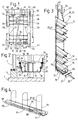
- a wall 1 of a part shown in FIG. 2 Building has a window 5 shown in simplified form. This has glazing 7 and borders an interior of the building against its surroundings.
- One in the figures 1 and 2 visible device 11 has one on the Outside of the window, i.e. in the floor plan on the Surroundings of the building facing the glazing 7 arranged protective element, shown separately in FIG. 3, namely a venetian blind 13 that serves as a curtain a first, upper end 14 and a second, lower end 15.
- the store has several, for example in essential slats 16 made of light metal sheet, the ends with plastic guide elements 17 are provided.
- the second, lower end 15 of the store is through an elongated, rod-shaped, hollow end member 18 educated.
- the various parts of the hollow end member 18 and in particular its lamella 19 and profile bar 20 are unsolvable as well as not separable without damage or at least connected with each other in such a way that they can only be Tools and / or only with great effort and time are separable from each other.
- the lamella 19 and the Profile bar 20 have, for example, interlocking Edges and can additionally at least in places be glued together.
- the end pieces 21 are for Example in the from the lamella 19 and from the profile bar 20th formed hollow rod inserted, screwed to this and possibly additionally glued to this.
- the venetian blind has at least two along the Slats 16 and the end member 18 spaced apart standing, consisting of a one-piece band, at the top End coherent and open loops at the bottom 24 on.
- the two strands of each loop 24 form a pair of opposing, elongated, flexible, Connecting elements 25 which the slats 16 and that Connect the end member 18 movably.
- Any fastener 25 extends from the first, upper end 14 to the second, lower end 15 of the store and is by each a holder 26 movable with each slat 16 and the End organ 18 connected.
- Each holder 26 is a ball joint formed and has two joint parts, of which the one on one edge of a slat 16 or 19 and the other is attached to a connecting element 25.
- the sidewalls of the profile bar 20 are for each connecting element 25 provided with a hole in which a spout 27 made of rubber or the like is attached.
- the lower unrelated Ends of the connecting elements 25 are through the Holes of the spouts 27 in the cavity of the end member 18th introduced and fixed in some way in the latter.
- a section of one belonging to a loop 24 Connecting element 25 is shown separately in FIG. 5 and has a band-shaped fabric 29 as the main component from electrically insulating, textile threads, for example made of plastic, such as polyamide and / or Polyester.
- the fabric 29 is near the an edge with one in the longitudinal direction of the connecting element trending, to increase the tensile strength serving reinforcing thread 30.
- This has a bundle of fibers from under the trade name Kevlar available aramid and at least one essentially completely wound around this fiber bundle, black, as opaque as possible, as light protection serving thread made of polyester.
- the fabric 29 is in the Proximity to his farther from the reinforcing thread 30 Provide longitudinal edge with a sensor element 31.
- the sensor element 31 has one running in the longitudinal direction of the connecting element, bendable core 32 and a winding around it, electrical conductor 33.
- the core 32 consists of an electrically insulating thread, for example made of twisted Polyamide and / or polyester fibers.
- the leader 33 consists of a bundle of fine twisted together or twisted fibers from a well bendable, metallic material, such as stainless steel.
- the Head 33 forms a helix, the slope of which is essential is greater than the thickness of the fiber bundle forming the conductor, leaving a space between each other following turns of the conductor is present.
- Metallic fibers of the conductor 33 are for example much shorter than the conductor 33 and a connecting element 25, so every metallic fiber just over a portion of the conductor and connector extends. However, it would also be possible for everyone metallic fiber of the conductor 33 without interruption above it extends the entire length.
- the conductors 33 of all loops 24 are in the cavity of the End organ 18 electrically connected in series and form together with a loop-like electrical line 34 two ends.
- the end organ 18 is equipped with monitoring means 35 provided that together with the sensor elements 31 Burglar alarms form, their electrical Circuit diagram in Fig. 6 can be seen.
- the Monitoring means 35 have an electronic Interrupt detector 36 and a test interrupter 37. The the latter is for example by an electrical, magnetically actuated normally closed switch contact, namely one Reed contact formed.
- Have the monitoring means at least one signal generator, namely an acoustic, for example piezoelectric signal generator 38, one optical, for example a light emitting diode with integrated Flashing signal transmitter 39 and possibly another in dash-dotted lines in the circuit diagram in FIG.
- the monitoring means 35 are electrically conductive with at least one battery 41 connected or provided, for example, only one only battery 41, namely only for the one time Provided, i.e. not rechargeable Lithium battery with a nominal voltage of 9 V and one Capacity or charge of at least or about 1 Ah is available.
- the battery 41 and the monitoring means 35 are at least substantially in the cavity of the End organ 18.
- the light emitting diode of the optical signal transmitter 39 may protrude through a hole in the window glazing 7 and the interior wall of the building Profile rod 20 a little from the cavity of the end member 18th out.
- any radio signal transmitter 40 possibly one that is outside the end organ Have antenna. If a radio signal transmitter 40 is present is a radio alarm signal generated by it in the form electromagnetic waves wirelessly onto one of the venetian blinds 13 removed somewhere in the building, for several Stores common central alarm device 43 transmitted become.
- the interruption detector 36 has a semiconductor switch 45 with a Darlington transistor circuit 46.
- This has two or more bipolar npn transistors integrated in a common housing, has three connections and is shown schematically as an npn transistor.
- the line 34 is electrically conductively connected to the Darlington transistor circuit 46 at two connection points. One of the ends of the line 34 and the negative pole of the battery are in fact directly connected to the emitter of the Darlington transistor circuit 46 and to the ground connection of the entire monitoring means 35 and, for example, to the metallic parts 19, 20 of the end element 18.
- the other end of line 34 is connected to the base of transistor circuit 46 via test breaker 37.
- the base of the transistor circuit is also connected via a resistor 47 to the positive pole of the battery.
- the collector of the transistor circuit is connected to a coil of a relay 49 via resistor 48.
- the relay 49 has a make contact which, in the closed state, connects the positive pole of the battery to the signal transmitter, so that the relay serves as an electrical signal transmitter.
- the Darlington transistor circuit 46 has a current amplification factor h fe of at least 20,000 and for example at least 30,000.
- the Darlington transistor circuit can consist, for example, of the transistor circuit available under the designation BC517 (Motorola). The large current gain enables a resistor 47 to be used, the resistance of which is at least 1 M ⁇ , better at least 3 M ⁇ and, for example, approximately 4.7 M ⁇ .
- the use of a Darlington transistor circuit with high current amplification and a high-resistance resistor 47 makes it possible to keep the current flowing through this and the interruption detector very low when the line 34 is intact.
- the current consumption of the line 34 and the entire monitoring means 35 is at most 10 ⁇ A, preferably at most 3 ⁇ A and, for example, at most or approximately 2 ⁇ A in the off state of the transistor circuit.
- the battery 41 can then keep the monitoring means in operation and ready for alarm for a period of at least 5 years and for example at least or about 10 years, without the battery having to be replaced or recharged or without any power being supplied from outside.
- the device 11 has two on the wall 1 of the Fixed vertical guides 51 with a building Profile bar. Each slat 16 is at its ends with the Guide elements 17 vertically displaceable and around a horizontal Axially pivoted in the guides 51. The end member 18 is horizontal by the bolts 22 Axis pivotally connected to two sliders 52, of each of which is vertically displaceable in one of the guides 51 is led.
- An actuator 55 has one in the upper ends of the guides attached to the wall 1, against bottom open support channel 56, which is a rotatably mounted Contains wave 57. This is through a drive device 58 rotatable, for example a manually operated Crank.
- Each slide 52 is characterized by an elongated, transmission element arranged in one of the guides 51, namely a toothed belt 59, with one on the shaft 57 seated gear 60 connected.
- a turning device 61 which can be actuated by the shaft 57 available.
- the fasteners 25 of each loop 24 are near their top, contiguous ends by short, particularly clearly visible in Fig. 3, such as additional connecting elements having cords or the like 62 with the associated turning device 61 connected so that the slats 16 so with the connecting elements 25 and additional connecting elements 62 suspended are.
- the holding member 63 has Example a rigid, metallic bracket or a Wire rope on, allows limited movements of the by the Loop 24 formed connecting elements 25 and is trained and attached so that it and its Connection with the support channel a greater strength than has the loop 24.
- the additional connecting elements 62 and Holding members 63 are completely within one arranged at the top of the window, not drawn, also containing the support channel 56, against bottom open storage box so that it is from the outside of the building are practically inaccessible.
- the Adjustment device supports the external venetian blind and enables this to adjust in the usual way, i.e. to lift or to lower and the slats 16 and the end organ around to pivot horizontal swivel axes.
- the lower, second end 15 of the venetian blind can through Rotation of the shaft 57 starting from that in FIGS 3 drawn position can be moved up, whereby the first, upper end 14 of the store raised a little at most and the store is gathered in the usual way.
- the store takes a release position one in which he has at least most of the Glazing 7 releases.
- the adjusting device 55, the connecting elements 25 and the transmission elements 59 are designed such that they all slats 16 and the end organ 18 in the Cover position of the store cannot be moved and cannot be swiveled hold tight. So it is not possible to get the store from to lift the outside of this and the building without destroying anything. However, if a burglar is under Use of violence tried the whole venetian blind or at least part of this away from the support channel 56 to tear down and / or slats 16 away from each other as well for example at least in part away from the end member 18 Moving up is practically inevitable at least a loop 24 forming a pair of connectors 25 in at least one place and probably mostly in two connecting elements belonging to the loop interrupted. This will cause at least one of the Sensor elements 31 and its conductor 33 interrupted.
- the electrical resistance of line 34 is very high much smaller than the resistance value of resistor 47. If line 34 is intact and the test breaker is closed, the base and emitter of the Darlington transistor circuit 46 therefore practically on the same potential. The transistor circuit is located then in the blocked state and the make contact of relay 49 is open. If at least one of the Sensor elements 31 and thus line 34 interrupted the Darlington transistor circuit gets into the Control state, so that the closing contact of relay 49 is closed and the signal generators 38, 39 electrical alarm signal, i.e. an electrical voltage feeds. The two signal generators 38, 39 then generate in turn an acoustic or visual alarm signal, for example a whistle or a sequence of colored ones or white light pulses.
- an acoustic or visual alarm signal for example a whistle or a sequence of colored ones or white light pulses.
- the end organ 18 also has a radio signal transmitter 40, this generates a electrical formed by electromagnetic waves Radio alarm signal and transmits it wirelessly to the central Alarm device 43, which is then also acoustic and / or generate visual alarm signals and / or a police station or alert another surveillance service can. Otherwise, the signal generator 38, 39 and the possible signal generator 40 after the triggering of a Alarms continuously alarm signals until the battery 41 discharges or until someone opens the end organ 18 and the Monitoring means 35 puts out of operation. Because the monitoring means 35 and the battery 41 at least in arranged substantially well protected within the end organ 18 and especially in the cover position of the store completely inaccessible from the outside of the housing are, it is almost impossible for a burglar to do that To put alarm security devices out of operation without first to trigger an alarm.
- each conductor 33 by a helix stainless steel fibers ensure good flexibility the conductor, so that this by the when adjusting the Venetian blind deformations of the sensor elements not be broken.
- the leaders are also steadfast against weather influences and therefore permanently.
- the test interrupter 37 connects the line 33 normally conductive with the break detector 36 and is arranged in the hollow end member 18 that it with a small permanent magnet through the wall of the end organ can be operated without contact and the connection the conductor 33 with the interruption detector 36 temporarily interrupts. If the monitoring means and the If the battery is ready for alarm, then alarm signals generated. The interrupter 37 thus enables control the battery and the function of the monitoring means.
- the battery due to a long installation time and / or discharged as a result of an alarm process it can be carried out by specialist personnel from the manufacturer of the Facility to be replaced, possibly the whole End organ 18 is replaced.
- the facility 7 shows a window 5 and one here with 111 designated facility shown.
- the facility 111 has a venetian blind 113, the slats, as a protective device 119, has a hollow end member 118 and loops 124, each of which is a pair of elongated connectors 125 forms.
- Each loop 124 in turn consists of an integral piece Band, but is at the top of this facility Open end and contiguous and penetrating at the lower end holes at the lower end with grommets End organ profile bars 118.
- Each connector 125 is provided with a sensor element 131, which is an electrical Has conductor 133.
- the store is through a Adjusting device 155 adjustable, the carrying channel 156 having.
- the monitoring means 135 are at this facility not in the end organ 118, but from the venetian blind 113 arranged away.
- the heads 133 of the various connecting elements facing each other in pairs are near the top ends of the fasteners 125 and actuator 155 electrically in series switched and together form a line 134 which with the interrupt detector of the monitoring means 135 connected is.
- the break detector as well acoustic signal generator of the monitoring means 135 and associated with and / or belonging to these Power supplies are, for example, at Actuating device 155 on the inside of the building Long side of the support channel 156 in the already mentioned not drawn storage box, so it from the environment of the building are practically inaccessible.
- the Power supply means have one, for example the AC power supply connected as well as at least a rechargeable buffer battery or one Accumulator.
- the monitoring means 135 still have at least one optical signal generator, for example is arranged so far from the support channel 156 that it Light in the room behind the glazing 7 of the building shines.
- the relay of the break detector and / or an additional electrical signal generator Monitoring means 135 may also be by electrical conductors with a relatively far from the store and from the Monitoring means 135 removed for multiple stores common, central alarm device.
- the from the AC network to the monitoring means 135 and this to an alarm device remote from the store leading conductors are shown schematically by arrows in FIG. 7 indicated.
- Each connecting element 25 and 125 can by one 8 connecting element 160 be replaced.
- This in turn is band-shaped and has one fabric and two in the longitudinal direction of the connecting element 160 running sensor elements 161, of which each similar to the sensor element shown in FIG. 5 31 and one designated 163 in FIG. 8, has electrical conductor.
- the opposing ones Fasteners can in turn be through dreams be formed in one piece and at the top or lower end related.
- the two leaders 163 can be electrical at one end of the loop, for example conductive with each other and at the other end of the loop Conductors from other fastener loops and / or be connected to the interruption detector.
- elongated, flexible Sensor element 171 has an optical fiber 173, which for Example a bundle of light-conducting fibers 175 made of mineral or organic glass, which in one Hose 177 are arranged.
- the light guides of the different For example, loops are optically connected in series and connected to monitoring means.
- the surveillance means are trained to work with at least one To generate light source continuously or in pulses as well as through the light guide and with one having at least one optoelectronic element Interruption detector in the event of an interruption in the light line to trigger an alarm.
- the sensor element 181 shown in FIG. 10 is elongated, limited a free, close to the environment closed cavity for receiving a fluid and consists, for example, of a thin, easily bendable Tube.
- connection elements forming loops, each with at least be provided with such a sensor element.
- sensor elements 181 are connected to each other, for example that they are sort of connected in series and together form a continuous line with one end Monitoring means connected and at the other end, for example is completed.
- the monitoring means have, for example one connected to the cavities of the sensor elements Fluid source to the cavities of the sensor elements a fluid, for example compressed air or another Gas with a pressure above the ambient air pressure feed.
- the monitoring means can then also one Interrupt detector with a pressure switch, the in case of an interruption of a sensor element in an electrical alarm signal caused this change in pressure generated.
- the sensor elements 171, 181 according to FIGS. 9 and 10 may have a core around which the Light guide or the one that delimits a free cavity Hose helical and analogous to the conductor 33 around the Core 32 run around.
- the protective device can also consist of a venetian blind, where there is little or no movement, first end below and the widely sliding second end and the end organ at the top of the store.
- the first, lower end of the store can then, for example, be constantly in are held in a recess in a window parapet, while the one at the second, upper end of the store End organ vertically displaceable by the adjusting device and is pivotable.
- the slats of this venetian blind are hung with fasteners on the end organ and can by lifting, lowering and pivoting the end organ as well be raised, lowered and swiveled.
- the Venetian blind takes in the highest possible position of the end organ the cover position and in the lowest possible position of the end organ the release position.
- the support elements are provided with sensor elements that are in a of the types described above and trained with monitoring means are connected. The latter can, for example analogous to that shown in Figures 1 to 7 Facilities at least to a large extent in the End organ or be arranged in the actuator.
- a device with a horizontal sliding venetian blinds are provided, the slats, a first end that cannot be moved or can only be moved slightly, a horizontal, for example, about the width of the Glazing of a window slidable by an end organ formed second end and elongated, flexible Has connecting elements, which from the first to the second End of the store and the slats as well as the end organ connect with each other and with an actuator. When the fasteners are stretched, they run with this variant of the store not from bottom to top, but horizontal.
- the connecting elements are the same as in the previously described devices with sensor elements provided that associated with monitoring means are.
- the device can be used instead of a venetian blind different type, provided with at least one sensor element
- Protective device for example a folding blind, roller shutters, Folding drawer, sliding shutter or an awning or the like exhibit. If the protective device comes from a roller shutter or Rolling armor exists, the actuator has a shaft and / or roller for winding and unwinding the roller shutter.
- the Roller shutter has a little height adjustable with which Shaft and / or roller connected, first end, one more Height adjustable, normally in the cover position second end below, a number of fixed Rods and at the second end a rod-shaped, possibly hollow Final organ.
- the rods and the end organ are through joints and / or elongated, flexible connecting elements, for example Belts or the like with each other and the shaft and / or roller connected. If the roller shutter all bars and the end organ connecting, flexible, made of belts or the like has existing connecting elements, can do this similar to the described connecting elements the venetian blinds are provided with sensor elements. If the roller shutter has no such connecting elements, can elongated, flexible sensor elements in any a way on all bars as well as the end organ of the shutter and possibly additionally on the shaft and / or roller be attached.
- the device as a protective device an awning owns, this can be the main component of a fabric exhibit. This is at the first end of the awning with a Shaft and / or roller connected to an actuator. At the the other, second end of the awning is a rigid, elongated, rod-shaped, possibly hollow end organ on the fabric attached.
- the awning is, for example, on the Outside of a window arranged that the end organ vertically adjustable by winding or unwinding the fabric and that the awning is in the cover position Glazing the window covers.
- the awning is with some distributed over its width, at least approximately from first to the second end of this extending sensor elements provided, for example, all by sections of a one-piece, coherent element or in pairs consist of loops that go from the second end to the first end and back to the second end or vice versa run.
- the sensor elements can be in and / or on the fabric, for example, parallel to the longitudinal edges the awning or crooked to it and / or zigzag or meandering.
- the sensor elements are further attached, for example, to the end organ and into the Fabric web woven or at least in some way almost uninterrupted over its entire length or at small distances from each other in and / or on the fabric and possibly at the first end of the Awning still on the shaft and / or roller of the Adjusting device attached. Furthermore, you may also still approximately parallel to the end organ, over the Sensor elements distributed over the length of the fabric his.
- the protective device comes from a folding blind, folding drawer or sliding shutter or the like, it can also with one or more at least approximately from first to the second end of the protective organ Be provided sensor element (s).
- the facilities can be changed in other ways become.
- the protective device is only narrow, may only need a single, a pair of sensor elements forming loop or even just a single sensor element to be provided.
- the band-shaped connecting elements 25, 125, 160 can by cord or rope-shaped connecting elements with an approximately circular cross-section be replaced.
- the different loops 24 of the first described Venetian blinds 13 associated holding members 63 can be done by a single, all loops 24 penetrating holding member to be replaced. Perhaps could the loops 24 even around the then additionally as Holding shaft 57 extending around and / or on Carrying channel or on immovable, rigid parts of the Turning devices 61 may be attached.
- the conductors 33, 163 fibers of copper or aluminum or a copper or aluminum alloy instead of fibers made of stainless steel.
- the ladder possibly with an electrical coaxial to them insulating jacket. If the protective organ like the venetian blind 13 through flexible transmission elements 59, for example toothed belt, with the adjusting device is connected, these transmission elements can possibly can also be provided with sensor elements. in the the rest of the protective device can instead of a window be arranged on the outside of a door.
- the Darlington transistor circuit can be pnp transistors instead of npn transistors, where then the battery with the reverse Polarity is connected to the transistor circuit. Furthermore, the interruption detector 36 and the signal generator 38, 39, 40 possibly by two or more separate batteries can be powered.
- the Monitoring means 135 of that shown in FIG. 7 Device 111 can instead of from the AC network also only from at least one battery with electricity be supplied, the battery can only be discharged once or can be rechargeable. Furthermore, the relay 49 by one of the Darlington transistor circuit 46 controlled semiconductor switch to be replaced.
- Trained circuit diagram can also be used for monitoring at least one electrically conductive sensor element provided that is not in a venetian blind or other protective organ of the type described is arranged, but possibly with one arranged in a protective organ Sensor element is connected in series, but not absolutely must be.
- Sensor element can be provided in a window or a door of a building or possibly a vehicle is arranged and when the window is opened violently or the door is interrupted.
- Such a sensor element can have, for example, a thin conductor which is arranged in such a way that when the window is opened or the door is torn.
- Such a sensor element can also an electrical switch contact, namely one Have normally closed contact that is normally closed and when opening, especially when opening by force, a window or door leaf is opened. If more such sensor elements are present, they can be electrical be connected in series and together a line form their ends with the Darlington transistor circuit are connected.
- Such low power Monitoring means are also for example Holiday homes without connection to the AC network or also for securing doors and / or windows from Suitable vehicles and the like and can then from at least one battery supplied with electrical current be, the or each battery can only be discharged once or be rechargeable.
Abstract
Description
Die Erfindung betrifft eine Einrichtung mit einem verstellbaren Schutzorgan zum Schutz gegen Licht und/oder Witterung und/oder Einbruch. Das verstellbare Schutzorgan ist insbesondere zum Anordnen an einer Wand eines Gebäudes auf der Aussenseite eines Fensters oder einer Tür vorgesehen und besteht beispielsweise aus einem Store, insbesondere einem Raffstore oder einem Faltstore oder einem Rolladen, Faltladen, Schiebeladen oder einer Markise.The invention relates to a device with a adjustable protective device for protection against light and / or Weather and / or burglary. The adjustable protective organ is particularly suitable for placing on a wall of a building provided on the outside of a window or door and consists for example of a store, in particular a venetian blind or a folding blind or one Roller shutters, folding shutters, sliding shutters or an awning.
Aus der DE 197 07 607 A bekannte Einrichtungen besitzen einen Raffstore mit Lamellen und einem am unteren Ende angeordneten, stabförmigen, vertikal verstellbaren Endorgan. Die Lamellen sind durch flexible Verbindungselemente, nämlich Bänder oder Schnüre, miteinander sowie mit einer Stellvorrichtung verbunden, und können mit der letzteren in verschiedene Stellungen verschwenkt werden. Wenn ein solcher Store in die tiefstmögliche Stellung abgesenkt ist, kann er beispielsweise eine Fensterverglasung abdecken und von aussen her nicht ohne Zerstörung irgendwelcher Teile angehoben werden. Falls jedoch ein Einbrecher die flexiblen Verbindungselemente trennt, kann er die Lamellen verschieben und dadurch die sich hinter dem Store befindende Fensterverglasung zugänglich machen sowie zerstören, wobei dies unter Umständen nicht sofort bemerkt wird.Have devices known from DE 197 07 607 A. a venetian blind with slats and one at the bottom arranged, rod-shaped, vertically adjustable end organ. The slats are through flexible connecting elements, namely ribbons or cords, with each other as well connected with an actuator, and can with the the latter can be pivoted into different positions. If such a store lowered to the lowest possible position is, for example, window glazing cover and from the outside not without destroying any Parts are lifted. If, however, a burglar separates the flexible connecting elements, he can the slats move and thereby the behind the store make existing window glazing accessible and destroy it, although this may not be noticed immediately becomes.
Ähnliche Nachteile ergeben sich bei einem Faltstore, Rolladen, Faltladen oder Schiebeladen oder bei einer Markise oder dergleichen. Similar disadvantages arise with a folding blind, Roller shutters, folding shutters or sliding shutters or with an awning or similar.
Der Erfindung liegt die Aufgabe zugrunde, Nachteile der bekannten Einrichtungen zu beheben und insbesondere einen unbemerkten Einbruch möglichst zu verhindern.The invention has for its object disadvantages to fix the known devices and in particular to prevent an unnoticed break-in if possible.
Diese Aufgabe wird nach der Erfindung durch eine Einrichtung gemäss dem Anspruch 1 gelöst. Vorteilhafte Ausgestaltungen der Einrichtung gehen aus den abhängigen Ansprüchen hervor.This object is achieved according to the invention by a device solved according to claim 1. Advantageous configurations the establishment go from the dependent claims forth.
Das Schutzorgan der erfindungsgemässen Einrichtung hat vorzugsweise ein nicht oder nur wenig verschiebbares, erstes Ende und ein (wesentlich mehr) verschiebbares, zweites Ende und kann zum Beispiel wahlweise in eine Abdeck-Stellung oder in eine Freigabe-Stellung gebracht werden, in der das Schutzorgan eine vorgesehene Fläche, zum Beispiel mindestens den grössten Teil der Verglasung eines Fensters oder eine Tür eines Gebäudes, abdeckt bzw. freigibt. Die Einrichtung ist zudem vorzugsweise derart ausgebildet, dass die beiden Enden des Schutzorgans in der Abdeck-Stellung mindestens annähernd unverschiebbar festgehalten werden. Das bzw. mindestens ein Sensorelement verläuft vorzugsweise mindestens annähernd vom ersten Ende zum zweiten Ende des Schutzorgans, wobei vorzugsweise, abhängig von der Breite des Schutzorgans, zwei oder mehr quer zur Verschieberichtung des zweiten Schutzorgan-Endes voneinander in Abstand stehende Sensorelemente vorhanden sind.The protective organ of the device according to the invention has preferably not or only slightly displaceable, first end and a (much more) movable, second End and can, for example, optionally in a cover position or be brought into a release position, in which the protective organ has a designated area, for example at least most of the glazing of a window or covers or releases a door of a building. The The device is also preferably designed such that the two ends of the protective member in the cover position at least approximately immovable. The or at least one sensor element preferably runs at least approximately from the first end to the second end of the Protective organ, preferably depending on the width of the protective organ, two or more transverse to the direction of displacement the second protective organ end at a distance from each other standing sensor elements are available.
Das mindestens eine Sensorelement des Schutzorgans und die Überwachungsmittel bilden zusammen Sicherungsmittel gegen Einbrüche. Wenn ein Einbrecher versucht, das sich in der Abdeck-Stellung befindende und in dieser gehaltene Schutzorgan zu öffnen, kann er dieses möglicherweise durch Gewaltanwendung derart beschädigen, dass die abgedeckte Fläche mindestens teilweise zugänglich wird. Bei geeigneter Ausbildung und Anordnung des mindestens einen Sensorelements wird bei einer Gewaltanwendung jedoch das oder mindestens ein Sensorelement unterbrochen. Die Überwachungmittel erzeugen dann mindestens ein Alarmsignal, beispielsweise mindestens ein elektrisches und/oder optisches und/oder akustisches Alarmsignal. Dadurch wird die Schutzwirkung des Schutzorgans gegen einen Einbruch wesentlich erhöht und die Gefahr erheblich reduziert, dass ein Einbrecher im Bereich des Schutzorgans unbemerkt in ein Gebäude eindringt.The at least one sensor element of the protective organ and the monitoring means together form security means against burglaries. If a burglar tries to get into the cover position and held in this Protective organ, he may be able to open it Damage violence in such a way that the covered Area is at least partially accessible. With more suitable Formation and arrangement of the at least one sensor element However, if or when violence is used, the or at least one sensor element interrupted. The surveillance media then generate at least one alarm signal, for example at least one electrical and / or optical and / or acoustic alarm signal. This will the protective effect of the protective organ against a break-in significantly increased and significantly reduced the risk that a burglar in the area of the security guard went unnoticed into one Building invades.
Bei einer vorteilhaften Ausgestaltung der Einrichtung sind mindestens ein wesentlicher Teil der Überwachungsmittel und eine bzw. jede zur Strom- bzw. Energieversorgung der Überwachungsmittel und zur allfälligen Erzeugung eines Alarmsignals erforderliche Batterie im und/oder am Schutzorgan selbst, zum Beispiel im wesentlichen in und/oder an einem am zweiten, verstellbaren Ende des Schutzorgans vorhandenen, hohlen Endorgan angeordnet. Das Endorgan ist vorzugsweise mit mindestens einem zu den Überwachungsmitteln gehörenden, optischen und/oder akustischen Signalgeber versehen. Das bzw. jedes Sensorelement, die Überwachungsmittel und die bzw. jede zur Energieversorgung dienende Batterie können dann vollständig im Herstellerwerk der Einrichtung in das Schutzorgan eingebaut und alarmbereit gemacht werden, so dass beim Montieren des Schutzzorgans an einem Gebäude oder sonstigen Verwendungsort weder elektrische Verbindungen erstellt noch sonstige Massnahmen getroffen werden müssen, um die Einbruchs-Sicherungsmittel alarmbereit zu machen. Das Schutzorgan ist bei dieser Ausgestaltung also in bezug auf die Einbruchssicherung sowie Erzeugung mindestens eines Alarmsignals völlig autonom, d.h. unabhängig von entfernt vom Schutzorgan angeordneten Teilen. In an advantageous embodiment of the device are at least a substantial part of the monitoring means and one or each for power supply of the monitoring means and for the generation of any Alarm signal required battery in and / or on the protective device itself, for example essentially in and / or on an existing at the second, adjustable end of the protective member, hollow end organ arranged. The final organ is preferably with at least one of the monitoring means belonging, optical and / or acoustic signal transmitter Mistake. The or each sensor element, the monitoring means and the or each serving for energy supply Batteries can then be completely in the manufacturing plant the device installed in the protective organ and ready for alarm be made so that when installing the protective device in a building or other place of use neither electrical connections nor other measures must be taken to secure the burglary alert. The protective organ is with this configuration, therefore, in relation to burglary protection and generation of at least one alarm signal completely autonomous, i.e. regardless of being away from the protective organ arranged parts.
Die in das Schutzorgan integrierten Überwachungsmittel können zusätzlich zu einem optischen und/oder akustischen Signalgeber oder eventuell anstelle eines solchen einen Signalgeber aufweisen, um ein Alarmsignal zu erzeugen und drahtlos, beispielsweise durch hochfrequente, elektromagnetische Wellen oder Ultraschall oder hörbaren Schall oder Infrarotlicht oder sichtbares Licht, zu einer vom Schutzorgan entfernten, zentralen, zum Beispiel mehreren verschiedenen Schutzorganen zugeordneten Alarmvorrichtung zu übertragen. Ferner kann ein zur Erzeugung eines elektrischen Alarmsignals dienender, in das Schutzorgan integrierter Signalgeber durch eine elektrisch leitende Verbindung mit einer vom Schutzorgan entfernten Alarmvorrichtung verbunden sein. In diesen Fällen sind das Schutzorgan und dessen Einbruchs-Sicherungsmittel noch teilweise autonom.The monitoring means integrated in the protective organ can in addition to an optical and / or acoustic Signal generator or possibly one instead of one Have signalers to generate an alarm signal and wirelessly, for example by high-frequency, electromagnetic Waves or ultrasound or audible sound or Infrared light or visible light, to one from the protective organ distant, central, for example several different ones Protective organs assigned to alarm device transfer. Furthermore, one for generating an electrical Alarm signal serving, integrated in the protective organ Signal generator through an electrically conductive connection connected to an alarm device remote from the protective organ his. In these cases, the protective organ and its Burglar alarm devices are still partially autonomous.
Bei einer anderen Ausgestaltung der erfindungsgemässen Einrichtung sind die Überwachungsmittel vom Schutzorgan entfernt, beispielsweise mindestens zum Teil bei und/oder in einer zum Verstellen des Schutzorgans dienenden Stellvorrichtung, angeordnet und in der Nähe von dieser mit dem bzw. jedem Sensorelement des Schutzorgans verbunden. Die Überwachungsmittel können dann mit Stromversorgungsmitteln versehen und/oder verbunden sein, die zum Beispiel an das elektrische Wechselstromnetz angeschlossen sind und/oder eine Batterie aufweisen. Die Überwachungsmittel und die Stromversorgungsmittel sollen in allen Fällen derart angeordnet sein, dass sie von der Aussenseite des Gebäudes und der Einrichtung her unzugänglich sind.In another embodiment of the invention The device is the means of monitoring by the protective organ removed, for example at least in part at and / or in an adjusting device used to adjust the protective member, arranged and close to this with the or each sensor element of the protective member connected. The Monitoring means can then be used with power supplies provided and / or connected, for example, to the electrical AC network are connected and / or have a battery. The surveillance means and the Power supplies should be like this in all cases be arranged from the outside of the building and are inaccessible to the facility.
Weitere Einzelheiten und Vorteile des Erfindungsgegenstands
werden anschliessend anhand von in den Zeichnungen
dargestellten Ausführungsbeispielen näher erläutert. In den
Zeichnungen zeigen
Eine zum Teil in Fig. 2 ersichtliche Wand 1 eines
Gebäudes weist ein vereinfacht dargestelltes Fenster 5 auf.
Dieses besitzt eine Verglasung 7 und grenzt einen Innenraum
des Gebäudes gegen dessen Umgebung ab. Eine in den Figuren
1 und 2 ersichtliche Einrichtung 11 besitzt ein auf der
Aussenseite des Fensters, d.h. im Grundriss auf der der
Umgebung des Gebäudes zugewandten Seite der Verglasung 7
angeordnetes, separat in Fig. 3 dargestelltes Schutzorgan,
nämlich einen als Behang dienenden Raffstore 13. Dieser hat
ein erstes, oberes Ende 14 und ein zweites, unteres Ende
15. Der Store besitzt mehrere, beispielsweise im
wesentlichen aus Leichtmetall-Blech bestehende Lamellen 16,
die an ihren Enden mit Führungsorganen 17 aus Kunststoff
versehen sind. Das zweite, untere Ende 15 des Stores ist
durch ein längliches, stabförmiges, hohles Endorgan 18
gebildet. Dieses besitzt eine gleich wie die Lamellen 16
ausgebildete Lamelle 19 und einen unter dieser
angeordneten, etwas vereinfacht auch in Fig. 4 dargestellten
Profilstab 20. An jedem Ende des Endorgans sind
ein Abschlussstück 21 und ein in der Längsrichtung des
Endorgans vom Abschlussstück weg nach aussen ragender
Bolzen 22 befestigt. Die Lamelle 19, der Profilstab 20 und
die beiden Abschlussstücke 21 begrenzen zusammen einen
Hohlraum und schliessen diesen im wesentlichen allseitig
gegen die Umgebung ab. Die Lamelle 19 und der Profilstab 20
des Endorgans bestehen aus metallischen, nicht-ferromagnetischen
Materialien, beispielsweise Leichtmetallen.
Die verschiedenen Teile des hohlen Endorgans 18 und insbesondere
dessen Lamelle 19 sowie Profilstab 20 sind unlösbar
sowie nicht ohne Beschädigung trennbar oder mindestens
derart miteinander verbunden, dass sie nur mit speziellen
Werkzeugen und/oder nur mit grossem Kraft- sowie Zeitaufwand
voneinander trennbar sind. Die Lamelle 19 und der
Profilstab 20 haben beispielsweise ineinander eingreifende
Ränder und können zusätzlich noch mindestens stellenweise
miteinander verklebt sein. Die Abschlussstücke 21 sind zum
Beispiel in den von der Lamelle 19 und vom Profilstab 20
gebildeten Hohlstab gesteckt, mit diesem verschraubt und
eventuell zusätzlich mit diesem verklebt.A wall 1 of a part shown in FIG. 2
Building has a
Der Raffstore weist mindestens zwei entlang den
Lamellen 16 und dem Endorgan 18 voneinander in Abstand
stehende, aus einem einstückigen Band bestehende, am oberen
Ende zusammenhängende und am unteren Ende offene Schleifen
24 auf. Die beiden Trume jeder Schleife 24 bilden ein Paar
von einander gegenüberstehenden, länglichen, flexiblen,
Verbindungselementen 25, welche die Lamellen 16 und das
Endorgan 18 beweglich miteinander verbinden. Jedes Verbindungselement
25 erstreckt sich vom ersten, oberen Ende 14
zum zweiten, unteren Ende 15 des Stores und ist durch je
einen Halter 26 beweglich mit jeder Lamelle 16 und dem
Endorgan 18 verbunden. Jeder Halter 26 ist als Kugelgelenk
ausgebildet und weist zwei Gelenkteile auf, von denen der
eine an einem Rand einer Lamelle 16 bzw. 19 und der andere
an einem Verbindungselement 25 befestigt ist. Die Seitenwände
des Profilstabs 20 sind für jedes Verbindungselement
25 mit einem Loch versehen, in dem eine Tülle 27 aus Gummi
oder dergleichen befestigt ist. Die unteren nicht zusammenhängenden
Enden der Verbindungselemente 25 sind durch die
Löcher der Tüllen 27 in den Hohlraum des Endorgans 18
eingeführt und in irgend einer Weise im letzteren fixiert.The venetian blind has at least two along the
Slats 16 and the
Ein Abschnitt von einem zu einer Schleife 24 gehörenden
Verbindungselement 25 ist separat in Fig. 5 dargestellt
und weist als Hauptbestandteil ein bandförmiges Gewebe 29
aus elektrisch isolierenden, textilen Fäden auf, die beispielsweise
aus Kunststoff, etwa Polyamid und/oder
Polyester, bestehen. Das Gewebe 29 ist in der Nähe des
einen Randes mit einem in der Längsrichtung des Verbindungselements
verlaufenden, zur Vergrösserung der Zugfestigkeit
dienenden Verstärkungsfaden 30 versehen. Dieser
besitzt ein Bündel Fasern aus unter dem Handelsnamen Kevlar
erhältlichem Aramid und mindestens einen im wesentlichen
lückenlos um dieses Faserbündel herum gewickelten,
schwarzen, möglichst lichtundurchlässigen, als Lichtschutz
dienenden Faden aus Polyester. Das Gewebe 29 ist in der
Nähe seines weiter vom Verstärkungsfaden 30 entfernten
Längsrands mit einem Sensorelement 31 versehen. Dieses
erstreckt sich unterbruchslos entlang der ganzen, ein Paar
einander gegenüberstehender Verbindungselemente bildenden
Schleife 24 und also insbesondere mindestens annähernd vom
zweiten Ende 15 zum ersten Ende 14 und wieder zurück zum
zweiten Ende 15 des Stores. Das Sensorelement 31 besitzt
einen in der Längsrichtung des Verbindungselements verlaufenden,
biegbaren Kern 32 und einen um diesen herum gewundenen,
elektrischen Leiter 33. Der Kern 32 besteht aus
einem elektrisch isolierenden Faden, zum Beispiel aus verzwirnten
Fasern aus Polyamid und/oder Polyester. Der Leiter
33 besteht aus einem Bündel von feinen, miteinander verdrillten
bzw. verzwirnten Fasern aus einem gut biegbaren,
metallischen Material, beispielsweise rostfreiem Stahl. Der
Leiter 33 bildet eine Wendel, deren Steigung wesentlich
grösser ist als die Dicke des den Leiter bildenden Faserbündels,
so dass ein Zwischenraum zwischen den aufeinander
folgenden Windungen des Leiters vorhanden ist. Die einzelnen,
metallischen Fasern des Leiters 33 sind beispielsweise
wesentlich kürzer als der Leiter 33 und ein Verbindungselement
25, so dass sich jede metallische Faser nur über
einen Abschnitt des Leiters und Verbindungselements
erstreckt. Es wäre jedoch auch möglich, dass sich jede
metallische Faser des Leiters 33 unterbruchslos über dessen
ganze Länge erstreckt.A section of one belonging to a
Die Leiter 33 aller Schleifen 24 sind im Hohlraum des
Endorgans 18 elektrisch in Serie geschaltet und bilden
zusammen eine schleifenartige, elektrische Leitung 34 mit
zwei Enden. Das Endorgan 18 ist mit Überwachungsmitteln 35
versehen, die zusammen mit den Sensorelementen 31
Einbruchs-Sicherungsmittel bilden, deren elektrisches
Schaltschema in Fig. 6 ersichtlich ist. Die
Überwachungsmittel 35 besitzen einen elektronischen
Unterbruchs-Detektor 36 und einen Test-Unterbrecher 37. Der
letztere ist beispielsweise durch einen elektrischen,
magnetisch betätigbaren Ruhe-Schaltkontakt, nämlich einen
Reed-Kontakt gebildet. Die Überwachungsmittel besitzen
mindestens einen Signalgeber, nämlich einen akustischen,
beispielsweise piezoelektrischen Signalgeber 38, einen
optischen, beispielsweise eine Leuchtdiode mit integrierter
Blinkschaltung aufweisenden Signalgeber 39 und eventuell
noch einem strichpunktiert im Schaltschema in Fig. 6
dargestellten Funk-Signalgeber 40. Die Überwachungsmittel
35 sind elektrisch leitend mit mindestens einer Batterie 41
verbunden bzw. versehen, wobei beispielsweise nur eine
einzige Batterie 41, nämlich eine nur für die einmalige
Entladung vorgesehene, d.h. nicht wiederaufladbare
Lithiumbatterie mit einer Nennspannung von 9 V und einer
Kapazität bzw. Ladung von mindestens oder ungefähr 1 Ah
vorhanden ist. Die Batterie 41 und die Überwachungsmittel
35 befinden sich mindestens im wesentlichen im Hohlraum des
Endorgans 18. Die Leuchtdiode des optischen Signalgebers 39
ragt jedoch eventuell durch ein Loch in der der FensterVerglasung
7 und dem Gebäude-Innenraum zugewandten Wand des
Profilstabs 20 ein wenig aus dem Hohlraum des Endorgans 18
heraus. Ferner kann der allfällige Funk-Signalgeber 40
eventuell eine sich ausserhalb des Endorgans befindende
Antenne aufweisen. Falls ein Funk-Signalgeber 40 vorhanden
ist, kann ein von diesem erzeugtes Funk-Alarmsignal in Form
elektromagnetischer Wellen drahtlos auf eine vom Raffstore
13 entfernt irgendwo im Gebäude angeordnete, für mehrere
Stores gemeinsame, zentrale Alarmvorrichtung 43 übertragen
werden. The
Der Unterbruchs-Dektektor 36 besitzt einen Halbleiter-Schalter
45 mit einer Darlington-Transistorschaltung 46.
Diese weist zwei oder mehr in ein gemeinsames Gehäuse
integrierte, bipolare npn-Transistoren auf, hat drei
Anschlüsse und ist schematisch als npn-Transistor
dargestellt. Die Leitung 34 ist bei zwei Verbindungsstellen
bzw. Anschlüssen der Darlington-Transistorschaltung 46
elektrisch leitend mit dieser verbunden. Eines der Enden
der Leitung 34 und der Minuspol der Batterie sind nämlich
direkt leitend mit dem Emitter der Darlington-Transistorschaltung
46, sowie dem Massenanschluss der
ganzen Überwachungsmittel 35 und beispielsweise mit den
metallischen Teilen 19, 20 des Endorgans 18 verbunden. Das
andere Ende der Leitung 34 ist über den Test-Unterbrecher
37 mit der Basis der Transistorschaltung 46 verbunden. Die
Basis der Transistorschaltung ist ferner über einen
Widerstand 47 mit dem Pluspol der Batterie verbunden. Der
Kollektor der Transistorschaltung ist über Widerstand 48
mit einer Spule von einem Relais 49 verbunden. Das Relais
49 hat einen Schliesskontakt, der in geschlossenem Zustand
den Pluspol der Batterie mit dem Signalgebern verbindet, so
dass das Relais als elektrischer Signalgeber dient. Die
Darlington-Transistorschaltung 46 hat einen
Stromverstärkungsfaktor hfe von mindestens 20'000 und
beispielsweise mindestens 30'000. Die Darlington-Transistorschaltung
kann zum Beispiel aus der unter der
Bezeichnung BC517 (Motorola)erhältlichen
Transistorschaltung bestehen. Die grosse Stromverstärkung
ermöglicht, einen Widerstand 47 zu verwenden, dessen
Widerstanswert mindestens 1 MΩ, bessser mindestens 3 MΩ
und zum Beispiel ungefähr 4,7 MΩ beträgt. Die Verwendung
einer Darlington-Transistorschaltung mit hoher
Stromverstärkung und eines hochohmigen Widerstandes 47
ermöglichen, den bei intakter Leitung 34 durch diese und
den Unterbruchs-Detektor fliessenden Strom sehr gering zu
halten. Der Stromverbrauch der Leitung 34 und der ganzen
Überwachungsmittel 35 beträgt im Sperrzustand der
Transistorschaltung höchstens 10 µA, besser höchstens 3 µA
und zum Beispiel höchstens oder ungefähr 2 µA. Die Batterie
41 kann dann die Überwachungsmittel während einer Zeitdauer
von mindestens 5 Jahren und beispielsweise mindestens oder
ungefähr 10 Jahren in Betrieb und alarmbereit halten, ohne
dass die Batterie ausgewechselt oder nachgeladen wird oder
dass sonst von aussen Strom zugeführt wird.The
Die Einrichtung 11 besitzt zwei an der Wand 1 des
Gebäudes befestigte, vertikale Führungen 51 mit einem
Profilstab. Jede Lamelle 16 ist an ihren Enden mit den
Führungsorganen 17 vertikal verschiebbar und um eine horizontale
Achse verschwenkbar in den Führungen 51 geführt.
Das Endorgan 18 ist durch die Bolzen 22 um eine horizontale
Achse verschwenkbar mit zwei Schiebern 52 verbunden, von
denen jeder vertikal verschiebbar in einer der Führungen 51
geführt ist. Eine Stellvorrichtung 55 besitzt einen bei den
oberen Enden der Führungen an der Wand 1 befestigten, gegen
unten offenen Tragkanal 56, der eine drehbar gelagerte
Welle 57 enthält. Diese ist durch eine Antriebsvorrichtung
58 drehbar, die zum Beispiel eine manuell betätigbare
Kurbel besitzt. Jeder Schieber 52 ist durch ein längliches,
in einer der Führungen 51 angeordnetes Übertragungselement,
nämlich einen Zahnriemen 59, mit einem auf der Welle 57
sitzenden Zahnrad 60 verbunden. Im Tragkanal 56 ist für
jedes Paar einander gegenüberstehender Verbindungselemente
25 eine durch die Welle 57 betätigbare Wendevorrichtung 61
vorhanden. Die Verbindungselemente 25 jeder Schleife 24
sind in der Nähe ihrer oberen, zusammenhängenden Enden
durch kurze, besonders deutlich in Fig. 3 ersichtliche,
etwa Schnüre oder dergleichen aufweisende Zusatz-Verbindungselemente
62 mit der zugeordneten Wendevorrichtung 61
verbunden, so dass die Lamellen 16 also mit den Verbindungselementen
25 sowie Zusatz-Verbindungselementen 62 aufgehängt
sind. Für jede Schleife 24 ist ein deren oberes
Ende durchdringendes Halteorgan 63 vorhanden und an einem
unbeweglichen Teil der der betreffenden Schleife
zugeordneten Wendevorrichtung 61 und/oder direkt am
Tragkanal 56 befestigt. Das Halteorgan 63 weist zum
Beispiel einen starren, metallischen Bügel oder ein
Drahtseil auf, erlaubt begrenzte Bewegungen der von der
Schleife 24 gebildeten Verbindungselemente 25 und ist
derart ausgebildet und befestigt, dass es und seine
Verbindung mit dem Tragkanal eine grössere Festigkeit als
die Schleife 24 hat. Die Zusatz-Verbindungselemente 62 und
Halteorgane 63 befinden sich vollständig innerhalb eines
beim oberen Ende des Fensters angeordneten, nicht
gezeichneten, auch den Tragkanal 56 enthaltenden, gegen
unten offenen Storekastens, so dass sie von der Aussenseite
des Gebäudes her praktisch nicht zugänglich sind. Die
Stellvorrichtung trägt den Raffstore und ermöglicht, diesen
in üblicher Weise zu verstellen, d.h. zu heben oder zu
senken und die Lamellen 16 sowie das Endorgan um
horizontale Schwenkachsen zu verschwenken.The
Wenn der Store - wie in den Figuren 1 bis 3 gezeichnet
- in die tiefstmögliche Stellung abgesenkt ist, werden alle
Lamellen 16 von den Verbindungselementen 25 getragen und in
Abstand voneinander sowie vom Endorgan 18 gehalten. Die
Lamellen 16 und das Endorgan 18 sind in den Figuren 1 bis 3
in einer Offen-Schwenkstellung gezeichnet, in der sie noch
relativ viel Licht durchlassen. Durch Drehen der Welle 57
können die Lamellen 16 und das Endorgan 18 über die Wendevorrichtungen
61 und die Verbindungselemente 25 in eine
Schliess-Schwenkstellung verschwenkt werden, in der sie
einander überlappen. Der Store gelangt dabei in die Abdeck-Stellung,
in welcher der Store die Verglasung 7 mindestens
annähernd vollständig und lückenlos abdeckt. Das Endorgan
wird beim Verschwenken in die Schliess-Schwenkstellung ausgehend
von seiner in Fig. 2 gezeichneten Offen-Stellung im
Uhrzeigersinn verschwenkt. Die Hauptstrahlungsrichtung oder
Strahlungsachse des optischen Signalgebers 39 ist dann
schräg nach oben gegen die Verglasung 7 gerichtet.If the store - as shown in Figures 1 to 3
- is lowered to the lowest possible position, all
Das untere, zweite Ende 15 des Raffstores kann durch
Drehen der Welle 57 ausgehend von der in den Figuren 1 bis
3 gezeichneten Stellung nach oben verschoben werden, wobei
das erste, obere Ende 14 des Stores höchstens wenig angehoben
und der Store in üblicher Weise gerafft wird. In der
höchstmöglichen Stellung nimmt der Store eine Freigabe-Stellung
ein, in der er mindestens den grössten Teil der
Verglasung 7 freigibt.The lower,
Die Stellvorrichtung 55, die Verbindungselemente 25
und die Übertragungselemente 59 sind derart ausgebildet,
dass sie alle Lamellen 16 und das Endorgan 18 in der
Abdeck-Stellung des Stores unverschiebbar und unverschwenkbar
festhalten. Es ist also nicht möglich, den Store von
der Aussenseite von diesem und dem Gebäude her zu heben,
ohne etwas zu zerstören. Wenn jedoch ein Einbrecher unter
Gewaltanwendung versucht, den ganzen Raffstore oder
mindestens einen Teil von diesem vom Tragkanal 56 weg nach
unten zu reissen und/oder Lamellen 16 voneinander weg sowie
beispielsweise mindestens zum Teil vom Endorgan 18 weg nach
oben zu bewegen, wird praktisch zwangsläufig mindestens
eine ein Paar Verbindungselemente 25 bildende Schleife 24
an mindestens einer Stelle und wahrscheinlich meistens bei
beiden zur Schleife gehörenden Verbindungselementen
unterbrochen. Dadurch werden mindestens eines der
Sensorelemente 31 und dessen Leiter 33 unterbrochen.The adjusting
Der elektrische Widerstand der Leitung 34 ist sehr
viel kleiner als der Widerstandswert des Widerstands 47.
Wenn die Leitung 34 intakt ist und der Test-Unterbrecher
geschlossen ist, liegen die Basis und der Emitter der
Darlington-Transistorschaltung 46 daher praktisch auf dem
gleichen Potential. Die Transistorschaltung befindet sich
dann im Sperrzustand und der Schliesskontakt des Relais 49
ist offen. Wenn bei einem Einbruch mindestens eines der
Sensorelemente 31 und damit die Leitung 34 unterbrochen
werden, gelangt die Darlington-Transistorschaltung in den
Leitzustand, so dass der Schliesskontakt des Relais 49
geschlossen wird und den Signalgebern 38, 39 ein
elektrisches Alarmsignal, d.h. eine elektrische Spannung
zuführt. Die beiden Signalgeber 38, 39 erzeugen dann
ihrerseits ein akustisches bzw. ein optisches Alarmsignal,
zum Beispiel einen Pfeifton bzw. eine Folge von farbigen
oder weissen Lichtimpulsen. Falls das Endorgan 18 auch noch
einen Funk-Signalgeber 40 aufweist, erzeugt dieser ein
durch elektromagnetische Wellen gebildetes, elektrisches
Funk-Alarmsignal und überträgt dieses drahtlos zur zentralen
Alarmvorrichtung 43, die dann ebenfalls akustische
und/oder optische Alarmsignale erzeugen und/oder eine Polizeistation
oder einen sonstigen Überwachungsdienst alarmieren
kann. Im übrigen erzeugen die Signalgeber 38, 39 und
der allfällige Signalgeber 40 nach der Auslösung eines
Alarms fortwährend Alarmsignale, bis die Batterie 41 entladen
ist oder bis jemand das Endorgan 18 öffnet und die
Überwachungsmittel 35 ausser Betrieb setzt. Da die Überwachungsmittel
35 sowie die Batterie 41 mindestens im
wesentlichen gut geschützt innerhalb des Endorgans 18 angeordnet
und insbesondere in der Abdeck-Stellung des Stores
von der Aussenseite des Gehäuses her vollständig unzugänglich
sind, ist es für einen Einbrecher fast unmöglich, die
Alarmsicherungsmittel ausser Betrieb zu setzen, ohne vorher
einen Alarm auszulösen. The electrical resistance of
Die Ausbildung jedes Leiters 33 durch eine Wendel aus
rostfreien Stahlfasern gewährleistet eine gute Biegbarkeit
der Leiter, so dass diese durch die beim Verstellen des
Raffstores stattfindenden Deformationen der Sensorelemente
nicht gebrochen werden. Die Leiter sind ferner beständig
gegen Witterungseinflüsse und also dauerhaft.The formation of each
Der Test-Unterbrecher 37 verbindet die Leitung 33
normalerweise leitend mit dem Unterbruchs-Detektor 36 und
ist derart im hohlen Endorgan 18 angeordnet, dass er mit
einem kleinen Permanentmagnet durch die Wand des Endorgans
hindurch berührungslos betätigt werden kann und die Verbindung
der Leiter 33 mit dem Unterbruchs-Detektor 36 vorübergehend
unterbricht. Wenn die Überwachungsmittel und die
Batterie alarmbereit sind, werden dann Alarmsignale
erzeugt. Der Unterbrecher 37 ermöglicht also eine Kontrolle
der Batterie und der Funktion der Überwachungsmittel.The
Wenn die Batterie infolge einer langen Installationsdauer
und/oder infolge eines Alarmierungsvorgangs entladen
ist, kann sie durch Fachpersonal der Herstellerin der
Einrichtung ersetzt werden, wobei eventuell das ganze
Endorgan 18 ausgewechselt wird.If the battery due to a long installation time
and / or discharged as a result of an alarm process
, it can be carried out by specialist personnel from the manufacturer of the
Facility to be replaced, possibly the
In Fig. 7 sind ein Fenster 5 und eine hier mit 111
bezeichnete Einrichtung dargestellt. Die Einrichtung 111
besitzt als Schutzorgan einen Raffstore 113, der Lamellen
119, ein hohles Endorgan 118 und Schleifen 124 aufweist,
von denen jede ein Paar längliche Verbindungselemente 125
bildet. Jede Schleife 124 besteht wiederum aus einem einstückigen
Band, ist aber bei dieser Einrichtung am oberen
Ende offen sowie am unteren Ende zusammenhängend und durchdringt
beim unteren Ende mit Tüllen versehene Löcher des
Profilstabs des Endorgans 118. Jedes Verbindungselement 125
ist mit einem Sensorelement 131 versehen, das einen elektrischen
Leiter 133 aufweist. Der Store ist durch eine
Stellvorrichtung 155 verstellbar, die einen Tragkanal 156
aufweist. Die Überwachungsmittel 135 sind bei dieser Einrichtung
nicht im Endorgan 118, sondern vom Raffstore 113
entfernt angeordnet. Die Leiter 133 der verschiedenen,
einander paarweise gegenüberstehenden Verbindungselemente
sind in der Nähe der oberen Enden der Verbindungselemente
125 und der Stellvorrichtung 155 elektrisch in Serie
geschaltet und bilden zusammen eine Leitung 134, die mit
dem Unterbruchs-Detektor der Überwachungsmittel 135
verbunden ist. Der Unterbruchs-Detektor sowie ein
akustischer Signalgeber der Überwachungsmittel 135 und die
mit diesen verbundenen und/oder zu diesen gehörenden
Stromversorgungsmittel befinden sich zum Beispiel bei der
Stellvorrichtung 155 auf der dem Gebäude-Innenraum zugewandten
Längsseite des Tragkanals 156 im schon erwähnten,
nicht gezeichneten Storekasten, so dass sie von der Umgebung
des Gebäudes her praktisch unzugänglich sind. Die
Stromversorgungsmittel besitzen beispielsweise einen mit
dem Wechselstromnetz verbundenen Netzteil sowie mindestens
eine wiederaufladbare Puffer-Batterie bzw. einen
Akkumulator. Die Überwachungsmittel 135 besitzen noch
mindestens einen optischen Signalgeber, der beispielsweise
derart entfernt vom Tragkanal 156 angeordnet ist, dass er
Licht in den sich hinter der Verglasung 7 befindenden Raum
des Gebäudes strahlt. Das Relais der Unterbruchs-Detektor
und/oder ein zusätzlicher, elektrischer Signalgeber der
Überwachungsmittel 135 kann ferner durch elektrische Leiter
mit einer relativ weit vom Store und von den
Überwachungsmitteln 135 entfernten, für mehrere Stores
gemeinsamen, zentralen Alarmvorrichtung verbunden sein. Die
vom Wechselstromnetz zu den Überwachungsmitteln 135 und von
dieser zu einer vom Store entfernten Alarmvorrichtung
führenden Leiter sind in Fig. 7 schematisch durch Pfeile
angedeutet. 7 shows a
Jedes Verbindungselement 25 und 125 kann durch ein
gemäss der Fig. 8 ausgebildetes Verbindungselement 160
ersetzt werden. Dieses ist wiederum bandförmig und besitzt
ein Gewebe und zwei in der Längsrichtung des Verbindungselements
160 verlaufende Sensorelemente 161, von denen
jedes ähnlich wie das in Fig. 5 ersichtliche Sensorelement
31 ausgebildet und einen in Fig. 8 mit 163 bezeichneten,
elektrischen Leiter aufweist. Die einander gegenüberstehenden
Verbindungselemente können wiederum durch Trume
einer einstückigen Schleife gebildet sein und am oberen
oder unteren Ende zusammenhängen. Die beiden Leiter 163
können beispielsweise am einen Ende der Schleife elektrisch
leitend miteinander und am anderen Ende der Schleife mit
Leitern von anderen Verbindungselement-Schleifen und/oder
mit dem Unterbruchs-Detektor verbunden sein.Each connecting
Das in Fig. 9 ersichtliche, längliche, flexible
Sensorelement 171 besitzt einen Lichtleiter 173, der zum
Beispiel ein Bündel von lichtleitenden Fasern 175 aus mineralischem
oder organischem Glas aufweist, die in einem
Schlauch 177 angeordnet sind. Die Lichtleiter der verschiedenen
Schleifen sind zum Beispiel optisch in Serie geschaltet
und mit Überwachungsmitteln verbunden. Die Überwachungsmittel
sind ausgebildet, um mit mindestens einer
Lichtquelle kontinuierlich oder impulsweise Licht zu erzeugen
sowie durch die Lichtleiter hindurch zu leiten und mit
einem mindestens ein opto-elektronisches Element aufweisenden
Unterbruchs-Detektor bei einem Unterbruch der Lichtleitung
einen Alarm auszulösen.9, elongated,
Das in Fig. 10 dargestellte Sensorelement 181 ist
länglich, begrenzt einen freien, dicht gegen die Umgebung
abgeschlossenen Hohlraum zum Aufnehmen eines Fluids und
besteht zum Beispiel aus einem dünnen, gut biegbaren
Schlauch. Es können beispielsweise wiederum mehrere, paarweise
Schleifen bildende Verbindungselemente mit je mindestens
einem solchen Sensorelement versehen werden. Die in
verschiedenen Verbindungselementen angeordneten Sensorelemente
181 sind beispielsweise miteinander verbunden, so
dass sie gewissermassen in Serie geschaltet sind und zusammen
eine fortlaufende Leitung bilden, die am einen Ende mit
Überwachungsmitteln verbunden und am andern Ende beispielsweise
abgeschlossen ist. Die Überwachungsmittel weisen beispielsweise
eine mit den Hohlräumen der Sensorelemente verbundene
Fluidquelle auf, um den Hohlräumen der Sensorelemente
ein Fluid, zum Beispiel Druckluft oder ein anderes
Gas mit einem über dem Umgebungs-Luftdruck liegenden Druck
zuzuführen. Die Überwachungsmittel können dann zudem einen
Unterbruchs-Detektor mit einem Druckwächter aufweisen, der
bei einer durch einen Unterbruch eines Sensorelements in
diesem verursachten Druckänderung ein elektrisches Alarmsignal
erzeugt.The
Die Sensorelemente 171, 181 gemäss den Figuren 9 und
10 können eventuell noch einen Kern aufweisen, um den der
Lichtleiter bzw. der einen freien Hohlraum begrenzende
Schlauch wendelförmig sowie analog wie der Leiter 33 um den
Kern 32 herum verlaufen.The
Das Schutzorgan kann auch aus einem Raffstore bestehen, bei dem sich das nicht oder nur wenig verschiebbare, erste Ende unten und das weit verschiebbare, zweite Ende sowie das Endorgan oben am Store befinden. Das erste, untere Ende des Stores kann dann beispielsweise dauernd in einer Ausnehmung einer Fensterbrüstung festgehalten werden, während das am zweiten, oberen Ende des Stores vorhandene Endorgan durch die Stellvorrichtung vertikal verschiebbar und verschwenkbar ist. Die Lamellen dieses Raffstores sind mit Verbindungselementen am Endorgan aufgehängt und können durch Heben, Senken und Verschwenken des Endorgans ebenfalls gehoben, gesenkt und verschwenkt werden. Der Raffstore nimmt in der höchstmöglichen Stellung des Endorgans die Abdeck-Stellung und in der tiefstmöglichen Stellung des Endorgans die Freigabe-Stellung ein. Die Tragelemente sind mit Sensorelementen versehen, die in einer der vorgängig beschriebenen Arten ausgebildet und mit Überwachungsmitteln verbunden sind. Die letzteren können beispielsweise analog wie bei den in den Figuren 1 bis 7 dargestellte Einrichtungen mindestens zu einem grossen Teil im Endorgan oder bei der Stellvorrichtung angeordnet werden.The protective device can also consist of a venetian blind, where there is little or no movement, first end below and the widely sliding second end and the end organ at the top of the store. The first, lower end of the store can then, for example, be constantly in are held in a recess in a window parapet, while the one at the second, upper end of the store End organ vertically displaceable by the adjusting device and is pivotable. The slats of this venetian blind are hung with fasteners on the end organ and can by lifting, lowering and pivoting the end organ as well be raised, lowered and swiveled. The Venetian blind takes in the highest possible position of the end organ the cover position and in the lowest possible position of the end organ the release position. The support elements are provided with sensor elements that are in a of the types described above and trained with monitoring means are connected. The latter can, for example analogous to that shown in Figures 1 to 7 Facilities at least to a large extent in the End organ or be arranged in the actuator.
Des weiteren kann eine Einrichtung mit einem horizontal verschiebbaren Raffstore vorgesehen werden, der Lamellen, ein nicht oder nur wenig verschiebbares, erstes Ende, ein beispielsweise horizontal ungefähr über die Breite der Verglasung eines Fensters verschiebbares, durch ein Endorgan gebildetes, zweites Ende und längliche, flexible Verbindungselemente aufweist, welche vom ersten zum zweiten Ende des Stores verlaufen und die Lamellen sowie das Endorgan miteinander und mit einer Stellvorrichtung verbinden. Wenn die Verbindungselemente gestreckt sind, verlaufen sie bei dieser Variante des Stores nicht von unten nach oben, sondern horizontal. Die Verbindungselemente sind analog wie bei den vorher beschriebenen Einrichtungen mit Sensorelementen versehen, die mit Überwachungsmitteln verbunden sind.Furthermore, a device with a horizontal sliding venetian blinds are provided, the slats, a first end that cannot be moved or can only be moved slightly, a horizontal, for example, about the width of the Glazing of a window slidable by an end organ formed second end and elongated, flexible Has connecting elements, which from the first to the second End of the store and the slats as well as the end organ connect with each other and with an actuator. When the fasteners are stretched, they run with this variant of the store not from bottom to top, but horizontal. The connecting elements are the same as in the previously described devices with sensor elements provided that associated with monitoring means are.
Die Einrichtung kann anstelle von einem Raffstore ein andersartiges, mit mindestens einem Sensorelement versehenes Schutzorgan, beispielsweise einen Faltstore, Rolladen, Faltladen, Schiebeladen oder eine Markise oder dergleichen aufweisen. Wenn das Schutzorgan aus einem Rolladen bzw. Rollpanzer besteht, besitzt die Stellvorrichtung eine Welle und/oder Walze zum Auf- und Abwickeln des Rolladens. Der Rolladen hat ein nur wenig höhenverstellbares, mit der Welle und/oder Walze verbundenes, erstes Ende, ein mehr höhenverstellbares, sich in der Abdeck-Stellung normalerweise unten befindendes, zweites Ende, eine Anzahl fester Stäbe und am zweiten Ende ein stabförmiges, eventuell hohles Endorgan. Die Stäbe und das Endorgan sind durch Gelenke und/oder längliche, flexible Verbindungselemente beispielsweise Gurte oder dergleichen miteinander sowie der Welle und/oder Walze verbunden. Falls der Rolladen alle Stäbe und das Endorgan miteinander verbindende, flexible, aus Gurten oder dergleichen bestehende Verbindungselemente besitzt, können diese ähnlich wie die beschriebenen Verbindungselemente der Raffstores mit Sensorelementen versehen sein. Wenn der Rolladen keine solchen Verbindungselemente aufweist, können längliche, flexible Sensorelemente in irgend einer Weise an allen Stäben sowie dem Endorgan des Rolladens und eventuell zusätzlich an der Welle und/oder Walze befestigt werden.The device can be used instead of a venetian blind different type, provided with at least one sensor element Protective device, for example a folding blind, roller shutters, Folding drawer, sliding shutter or an awning or the like exhibit. If the protective device comes from a roller shutter or Rolling armor exists, the actuator has a shaft and / or roller for winding and unwinding the roller shutter. The Roller shutter has a little height adjustable with which Shaft and / or roller connected, first end, one more Height adjustable, normally in the cover position second end below, a number of fixed Rods and at the second end a rod-shaped, possibly hollow Final organ. The rods and the end organ are through joints and / or elongated, flexible connecting elements, for example Belts or the like with each other and the shaft and / or roller connected. If the roller shutter all bars and the end organ connecting, flexible, made of belts or the like has existing connecting elements, can do this similar to the described connecting elements the venetian blinds are provided with sensor elements. If the roller shutter has no such connecting elements, can elongated, flexible sensor elements in any a way on all bars as well as the end organ of the shutter and possibly additionally on the shaft and / or roller be attached.
Falls die Einrichtung als Schutzorgan eine Markise besitzt, kann diese als Hauptbestandteil eine Stoffbahn aufweisen. Diese ist am ersten Ende der Markise mit einer Welle und/oder Walze einer Stellvorrichtung verbunden. Am anderen, zweiten Ende der Markise ist ein starres, längliches, stabförmiges, eventuell hohles Endorgan an der Stoffbahn befestigt. Die Markise ist zum Beispiel derart an der Aussenseite eines Fensters angeordnet, dass das Endorgan durch Auf- oder Abwickeln der Stoffbahn vertikal verstellbar ist und dass die Markise in der Abdeck-Stellung die Verglasung des Fensters abdeckt. Die Markise ist mit einigen über ihre Breite verteilten, mindestens annähernd vom ersten zum zweiten Ende von dieser verlaufenden Sensorelementen versehen, die zum Beispiel alle durch Abschnitte eines einstückigen, zusammenhängenden Elements oder paarweise aus Schleifen bestehen, die vom zweiten Ende zum ersten Ende und wieder zurück zum zweiten Ende oder umgekehrt verlaufen. Die Sensorelemente können in und/oder an der Stoffbahn beispielsweise parallel zu den Längsrändern der Markise oder schief zu diesen und/oder zickzackförmig oder mäanderförmig verlaufen. Die Sensorelemente sind ferner zum Beispiel am Endorgan befestigt und in die Stoffbahn eingewoben oder in irgend einer Weise mindestens annähernd über ihre ganze Länge unterbruchslos oder bei kleinen Abständen voneinander stehenden Stellen in und/oder an der Stoffbahn sowie eventuell beim ersten Ende der Markise noch an der Welle und/oder Walze der Stellvorrichtung befestigt. Ferner können eventuell auch noch ungefähr parallel zum Endorgan verlaufende, über die Länge der Stoffbahn verteilte Sensorelemente vorhanden sein.If the device as a protective device an awning owns, this can be the main component of a fabric exhibit. This is at the first end of the awning with a Shaft and / or roller connected to an actuator. At the the other, second end of the awning is a rigid, elongated, rod-shaped, possibly hollow end organ on the fabric attached. The awning is, for example, on the Outside of a window arranged that the end organ vertically adjustable by winding or unwinding the fabric and that the awning is in the cover position Glazing the window covers. The awning is with some distributed over its width, at least approximately from first to the second end of this extending sensor elements provided, for example, all by sections of a one-piece, coherent element or in pairs consist of loops that go from the second end to the first end and back to the second end or vice versa run. The sensor elements can be in and / or on the fabric, for example, parallel to the longitudinal edges the awning or crooked to it and / or zigzag or meandering. The sensor elements are further attached, for example, to the end organ and into the Fabric web woven or at least in some way almost uninterrupted over its entire length or at small distances from each other in and / or on the fabric and possibly at the first end of the Awning still on the shaft and / or roller of the Adjusting device attached. Furthermore, you may also still approximately parallel to the end organ, over the Sensor elements distributed over the length of the fabric his.
Falls das Schutzorgan aus einem Faltstore, Faltladen oder Schiebeladen oder dergleichen besteht, kann es ebenfalls mit einem oder mehreren mindestens annähernd vom ersten zum zweiten Ende des Schutzorgans verlaufenden Sensorelement(en) versehen sein.If the protective device comes from a folding blind, folding drawer or sliding shutter or the like, it can also with one or more at least approximately from first to the second end of the protective organ Be provided sensor element (s).
Die Einrichtungen können noch auf andere Arten geändert
werden. Man kann insbesondere Merkmale der verschiedenen,
vorgängig beschriebenen Ausführungsbeispiele miteinander
kombinieren. Falls das Schutzorgan nur schmal ist,
braucht eventuell nur eine einzige, ein Paar Sensorelemente
bildende Schleife oder sogar nur ein einziges Sensorelement
vorgesehen zu werden. Die bandförmigen Verbindungselemente
25, 125, 160 können durch schnur- bzw. seilförmige Verbindungselemente
mit ungefähr kreisförmigem Querschnitt
ersetzt werden. Die den verschiedenen Schleifen 24 des
zuerst beschriebenen Raffstores 13 zugeordneten Halteorgane
63 können durch ein einziges, alle Schleifen 24
durchdringendes Halteorgan ersetzt werden. Eventuell
könnten die Schleifen 24 sogar um die dann zusätzlich als
Halteorgan dienende Welle 57 herum verlaufen und/oder am
Tragkanal oder an unbeweglichen, starren Teilen der
Wendevorrichtungen 61 befestigt sein. Des weiteren können
die Leiter 33, 163 Fasern aus Kupfer oder Aluminium oder
einer Kupfer- oder Aluminiumlegierung anstelle von Fasern
aus rostfreiem Stahl aufweisen. Ferner können die Leiter
eventuell mit einem zu ihnen koaxialen, elektrisch
isolierenden Mantel versehen sein. Falls das Schutzorgan
wie der Raffstore 13 durch flexible Übertragungselemente
59, beispielsweise Zahnriemen, mit der Stellvorrichtung
verbunden ist, können diese Übertragungselemente eventuell
ebenfalls noch mit Sensorelementen versehen werden. Im
übrigen kann das Schutzorgan statt bei einem Fenster auf
der Aussenseite einer Tür angeordnet sein.The facilities can be changed in other ways
become. One can in particular distinguish features of the different
previously described embodiments with each other
combine. If the protective device is only narrow,
may only need a single, a pair of sensor elements
forming loop or even just a single sensor element
to be provided. The band-shaped connecting
Die Darlington-Transistorschaltung kann pnp-Transistoren
anstelle von npn-Transistoren aufweisen, wobei
dann die Batterie selbstveständlich mit umgekehrter
Polarität mit der Transistorschaltung verbunden wird.
Ferner können der Unterbruchs-Detektor 36 und die
signalgeber 38, 39, 40 eventuell durch zwei oder mehr
separate Batterien mit Strom versorgt werden. Die
Überwachungsmittel 135 der in Fig. 7 dargestellten
Einrichtung 111 können statt aus dem Wechselstromnetz
ebenfalls nur von mindestens einer Batterie mit Strom
versorgt werden, wobei die Batterie nur einmal entladbar
oder wiederaufladbar sein kann. Ferner kann das Relais 49
durch einen von der Darlington-Transistorschaltung 46
gesteuerten Halbleiter-Schalter ersetzt werden.The Darlington transistor circuit can be pnp transistors
instead of npn transistors, where
then the battery with the reverse
Polarity is connected to the transistor circuit.
Furthermore, the
Überwachungsmittel mit einer Darlington-Transistorschaltung und einem ungefähr gemäss Fig. 6 ausgebildeten Schaltschema können auch zur Überwachung mindestens eines elektrisch leitenden Sensorelements vorgesehen werden, das nicht in einem Raffstore oder sonstigen Schutzorgan der beschriebenen Art angeordnet ist, aber eventuell mit einem in einem Schutzorgan angeordneten Sensorelement in Serie geschaltet ist, dies jedoch nicht unbedingt sein muss. Es kann beispielsweise mindestens ein Sensorelement vorgesehen sein, das bei einem Fenster oder einer Tür eines Gebäudes oder eventuell eines Fahrzeugs angeordnet ist und beim gewaltsamen Öffnen des Fensters bzw. der Tür unterbrochen wird. Ein solches Sensorelement kann beispielsweise einen dünnen Leiter aufweisen, der derart angeordnet ist, dass er beim Aufbrechen des Fensters oder der Tür zerrissen wird. Ein solches Sensorelement kann ferner einen elektrischen Schaltkontakt, nämlich einen Ruhekontakt aufweisen, der normalerweise geschlossen ist und beim Öffnen, insbesondere beim gewaltsamen Öffnen, eines Fenster- oder Türflügels geöffnet wird. Falls mehrere solche Sensorelemente vorhanden sind, können sie elektrisch in Serie geschaltet werden und zusammen eine Leitung bilden, deren Enden mit der Darlington-Transistorschaltung verbunden sind. Solche nur wenig Strom benötigende Überwachungsmittel sind beispielsweise auch für Ferienhäuser ohne Anschluss an das Wechselstromnetz oder auch für die Sicherung von Türen und/oder Fenstern von Fahrzeugen und dergleichen geeignet und können dann aus mindestens einer Batterie mit elektrischem Strom versorgt werden, wobei die bzw. jede Batterie nur einmal entladbar oder wiederaufladbar sein.Monitoring means with a Darlington transistor circuit and approximately according to FIG. 6 Trained circuit diagram can also be used for monitoring at least one electrically conductive sensor element provided that is not in a venetian blind or other protective organ of the type described is arranged, but possibly with one arranged in a protective organ Sensor element is connected in series, but not absolutely must be. For example, there can be at least one Sensor element can be provided in a window or a door of a building or possibly a vehicle is arranged and when the window is opened violently or the door is interrupted. Such a sensor element can have, for example, a thin conductor which is arranged in such a way that when the window is opened or the door is torn. Such a sensor element can also an electrical switch contact, namely one Have normally closed contact that is normally closed and when opening, especially when opening by force, a window or door leaf is opened. If more such sensor elements are present, they can be electrical be connected in series and together a line form their ends with the Darlington transistor circuit are connected. Such low power Monitoring means are also for example Holiday homes without connection to the AC network or also for securing doors and / or windows from Suitable vehicles and the like and can then from at least one battery supplied with electrical current be, the or each battery can only be discharged once or be rechargeable.
Schliesslich wird noch auf die schon zitierte DE 197 07 607 A und die schweizerische Patentanmeldung 1664/97 sowie die entsprechende europäische Patentanmeldung 98 810 612 verwiesen, deren Inhalt hiermit in die vorliegende Anmeldung einbezogen wird, soweit sich keine Widersprüche ergeben.Finally, we will refer to the one already quoted DE 197 07 607 A and the Swiss patent application 1664/97 and the corresponding European patent application 98 810 612, the content of which is hereby incorporated into the the present application is included, insofar as none Contradictions arise.
Claims (12)
Applications Claiming Priority (2)
| Application Number | Priority Date | Filing Date | Title |
|---|---|---|---|
| CH254198 | 1998-12-23 | ||
| CH254198 | 1998-12-23 |
Publications (3)
| Publication Number | Publication Date |
|---|---|
| EP1013873A2 true EP1013873A2 (en) | 2000-06-28 |
| EP1013873A3 EP1013873A3 (en) | 2000-07-26 |
| EP1013873B1 EP1013873B1 (en) | 2005-07-27 |
Family
ID=4236119
Family Applications (1)
| Application Number | Title | Priority Date | Filing Date |
|---|---|---|---|
| EP99811007A Expired - Lifetime EP1013873B1 (en) | 1998-12-23 | 1999-11-03 | Safety device against light and/or weather and/or burglary |
Country Status (3)
| Country | Link |
|---|---|
| EP (1) | EP1013873B1 (en) |
| AT (1) | ATE300658T1 (en) |
| DE (1) | DE59912322D1 (en) |
Cited By (5)
| Publication number | Priority date | Publication date | Assignee | Title |
|---|---|---|---|---|
| FR2885941A1 (en) * | 2005-05-23 | 2006-11-24 | Diffus Est Soc Par Actions Sim | CURVED ANTI-INTRUSION DEVICE COMPRISING POLYMER MODULES ASSEMBLED BY HIGH-VOLTAGE CONDUCTOR BARS THROUGH INTERCEDIED FLOWER WASHERS OF HINGES |
| EP1852569A2 (en) * | 2006-05-03 | 2007-11-07 | Bertelli Materie Plastische S.p.A. | Locking device for a roller shutter |
| CH704200A1 (en) * | 2010-12-10 | 2012-06-15 | Griesser Holding Ag | Device for guiding slats in venetian blinds. |
| CN108412401A (en) * | 2018-02-11 | 2018-08-17 | 广西夜狼电子安防有限公司 | A kind of automatic window guardrail with safety protection function |
| DE212020000758U1 (en) | 2019-11-04 | 2022-07-18 | Zorluteks Tekstll Tlcaret Ve Sanayl Anonlm Slrketl | curtain alarm system |
Citations (5)
| Publication number | Priority date | Publication date | Assignee | Title |
|---|---|---|---|---|
| US4060803A (en) * | 1976-02-09 | 1977-11-29 | Audio Alert, Inc. | Security alarm system with audio monitoring capability |
| FR2418504A1 (en) * | 1978-02-24 | 1979-09-21 | Alsthom Cgee | Door or window break-in detector - uses fibre optic encased in panel and having ends terminated at light emitter-receiver |
| DE3012845A1 (en) * | 1980-04-02 | 1981-10-08 | Georg 6101 Reichelsheim Treusch | Roller shutter advance intrusion alarm system - has two contacts activated simultaneously by forcible raising, and wire releasing alarm if torn |
| DE4008441A1 (en) * | 1990-03-16 | 1991-09-19 | Rolf Prettl | Roller shutter with transverse slats in side guides - has current conductors on slats coupled to alarm for protection against intruder |
| DE4443550A1 (en) * | 1994-12-07 | 1996-06-13 | Vincent Huang | Electronic antitheft protection with lock circuit |
-
1999
- 1999-11-03 EP EP99811007A patent/EP1013873B1/en not_active Expired - Lifetime
- 1999-11-03 DE DE59912322T patent/DE59912322D1/en not_active Expired - Fee Related
- 1999-11-03 AT AT99811007T patent/ATE300658T1/en not_active IP Right Cessation
Patent Citations (5)
| Publication number | Priority date | Publication date | Assignee | Title |
|---|---|---|---|---|
| US4060803A (en) * | 1976-02-09 | 1977-11-29 | Audio Alert, Inc. | Security alarm system with audio monitoring capability |
| FR2418504A1 (en) * | 1978-02-24 | 1979-09-21 | Alsthom Cgee | Door or window break-in detector - uses fibre optic encased in panel and having ends terminated at light emitter-receiver |
| DE3012845A1 (en) * | 1980-04-02 | 1981-10-08 | Georg 6101 Reichelsheim Treusch | Roller shutter advance intrusion alarm system - has two contacts activated simultaneously by forcible raising, and wire releasing alarm if torn |
| DE4008441A1 (en) * | 1990-03-16 | 1991-09-19 | Rolf Prettl | Roller shutter with transverse slats in side guides - has current conductors on slats coupled to alarm for protection against intruder |
| DE4443550A1 (en) * | 1994-12-07 | 1996-06-13 | Vincent Huang | Electronic antitheft protection with lock circuit |
Cited By (7)
| Publication number | Priority date | Publication date | Assignee | Title |
|---|---|---|---|---|
| FR2885941A1 (en) * | 2005-05-23 | 2006-11-24 | Diffus Est Soc Par Actions Sim | CURVED ANTI-INTRUSION DEVICE COMPRISING POLYMER MODULES ASSEMBLED BY HIGH-VOLTAGE CONDUCTOR BARS THROUGH INTERCEDIED FLOWER WASHERS OF HINGES |
| EP1852569A2 (en) * | 2006-05-03 | 2007-11-07 | Bertelli Materie Plastische S.p.A. | Locking device for a roller shutter |
| EP1852569A3 (en) * | 2006-05-03 | 2012-07-25 | Bertelli Materie Plastische S.p.A. | Locking device for a roller shutter |
| CH704200A1 (en) * | 2010-12-10 | 2012-06-15 | Griesser Holding Ag | Device for guiding slats in venetian blinds. |
| CN108412401A (en) * | 2018-02-11 | 2018-08-17 | 广西夜狼电子安防有限公司 | A kind of automatic window guardrail with safety protection function |
| CN108412401B (en) * | 2018-02-11 | 2020-02-07 | 台州中知英健机械自动化有限公司 | Automatic window guardrail with security protection function |
| DE212020000758U1 (en) | 2019-11-04 | 2022-07-18 | Zorluteks Tekstll Tlcaret Ve Sanayl Anonlm Slrketl | curtain alarm system |
Also Published As
| Publication number | Publication date |
|---|---|
| EP1013873B1 (en) | 2005-07-27 |
| DE59912322D1 (en) | 2005-09-01 |
| EP1013873A3 (en) | 2000-07-26 |
| ATE300658T1 (en) | 2005-08-15 |
Similar Documents
| Publication | Publication Date | Title |
|---|---|---|
| EP0397179B1 (en) | Window system for a building | |
| DE3015072C2 (en) | Garage door operation control device | |
| AT405074B (en) | GATE, ESPECIALLY SLIDING GATE | |
| CH678749A5 (en) | ||
| EP1856355B1 (en) | Window or door | |
| DE4407342C2 (en) | Blackout device with an awning, an external blind or the like | |
| DE2934122A1 (en) | Window or door screen system - has light and air permeable curtain on support whose top edge is connectable to venetian blind bottom edge | |
| EP1013873B1 (en) | Safety device against light and/or weather and/or burglary | |
| EP1826357A2 (en) | Roller blind actuated by a fire detector | |
| DE202006020317U1 (en) | Motor-driven gate and door drive device and communication device for this purpose | |
| DE4131580A1 (en) | ARRANGEMENT FOR DEFINING THE AREA BETWEEN TWO LIMITING ELEMENTS, IN PARTICULAR THE PASSAGE OF AN ELECTRIC FENCE | |
| EP1271439B1 (en) | Device for monitoring the closure state of doors and windows | |
| EP0267358A1 (en) | Take-up device for raising and lowering a take-up curtain | |
| DE60201287T2 (en) | Motorized roller shutter with device for switching off a motor drive when an obstacle is detected | |
| DE202008013354U1 (en) | Detection device and closure device of a wall opening with detection device | |
| DE2644142A1 (en) | Intruder resistant mechanical roller shutter - comprises rollable strip spring elements pressing blind away from spindle into corner of housing | |
| DE4008441A1 (en) | Roller shutter with transverse slats in side guides - has current conductors on slats coupled to alarm for protection against intruder | |
| DE69916566T2 (en) | Burglar-resistant device, in particular for the protection of apartments | |
| DE19846652A1 (en) | Protective cover against intruder with insect filter esp. for roller blinds or window shutters | |
| EP2138673B1 (en) | Sun protection facility with emergency folding facility | |
| DE102019110142A1 (en) | Motorized sun protection | |
| EP0299219A1 (en) | Method and device for securing windows doors etc. against burglary | |
| DE102007034430A1 (en) | Security system with roller shutter plating which can be wound onto shaft has transmitting device connected to broken-glass sensor and transmits control signals which are characteristic for breaking of glass of sensor | |
| EP3488741B1 (en) | Device for moving a slider for opening or closing a zipper | |
| DE202009005248U1 (en) | Building with at least one building opening and a building closure |
Legal Events
| Date | Code | Title | Description |
|---|---|---|---|
| PUAI | Public reference made under article 153(3) epc to a published international application that has entered the european phase |
Free format text: ORIGINAL CODE: 0009012 |
|
| PUAL | Search report despatched |
Free format text: ORIGINAL CODE: 0009013 |
|
| AK | Designated contracting states |
Kind code of ref document: A2 Designated state(s): AT CH DE IT LI |
|
| AX | Request for extension of the european patent |
Free format text: AL;LT;LV;MK;RO;SI |
|
| AK | Designated contracting states |
Kind code of ref document: A3 Designated state(s): AT BE CH CY DE DK ES FI FR GB GR IE IT LI LU MC NL PT SE |
|
| AX | Request for extension of the european patent |
Free format text: AL;LT;LV;MK;RO;SI |
|
| 17P | Request for examination filed |
Effective date: 20001102 |
|
| AKX | Designation fees paid |
Free format text: AT CH DE IT LI |
|
| 17Q | First examination report despatched |
Effective date: 20030121 |
|
| GRAP | Despatch of communication of intention to grant a patent |
Free format text: ORIGINAL CODE: EPIDOSNIGR1 |
|
| GRAS | Grant fee paid |
Free format text: ORIGINAL CODE: EPIDOSNIGR3 |
|
| GRAA | (expected) grant |
Free format text: ORIGINAL CODE: 0009210 |
|
| AK | Designated contracting states |
Kind code of ref document: B1 Designated state(s): AT CH DE IT LI |
|
| REG | Reference to a national code |
Ref country code: CH Ref legal event code: EP |
|
| REF | Corresponds to: |
Ref document number: 59912322 Country of ref document: DE Date of ref document: 20050901 Kind code of ref document: P |
|
| REG | Reference to a national code |
Ref country code: CH Ref legal event code: NV Representative=s name: BRAUNPAT BRAUN EDER AG |
|
| PLBE | No opposition filed within time limit |
Free format text: ORIGINAL CODE: 0009261 |
|
| STAA | Information on the status of an ep patent application or granted ep patent |
Free format text: STATUS: NO OPPOSITION FILED WITHIN TIME LIMIT |
|
| 26N | No opposition filed |
Effective date: 20060428 |
|
| PGFP | Annual fee paid to national office [announced via postgrant information from national office to epo] |
Ref country code: DE Payment date: 20081107 Year of fee payment: 10 Ref country code: CH Payment date: 20081117 Year of fee payment: 10 |
|
| PGFP | Annual fee paid to national office [announced via postgrant information from national office to epo] |
Ref country code: AT Payment date: 20081112 Year of fee payment: 10 |
|
| PGFP | Annual fee paid to national office [announced via postgrant information from national office to epo] |
Ref country code: IT Payment date: 20081126 Year of fee payment: 10 |
|
| REG | Reference to a national code |
Ref country code: CH Ref legal event code: PL |
|
| PG25 | Lapsed in a contracting state [announced via postgrant information from national office to epo] |
Ref country code: AT Free format text: LAPSE BECAUSE OF NON-PAYMENT OF DUE FEES Effective date: 20091103 |
|
| PG25 | Lapsed in a contracting state [announced via postgrant information from national office to epo] |
Ref country code: LI Free format text: LAPSE BECAUSE OF NON-PAYMENT OF DUE FEES Effective date: 20091130 Ref country code: CH Free format text: LAPSE BECAUSE OF NON-PAYMENT OF DUE FEES Effective date: 20091130 |
|
| PG25 | Lapsed in a contracting state [announced via postgrant information from national office to epo] |
Ref country code: DE Free format text: LAPSE BECAUSE OF NON-PAYMENT OF DUE FEES Effective date: 20100601 |
|
| PG25 | Lapsed in a contracting state [announced via postgrant information from national office to epo] |
Ref country code: IT Free format text: LAPSE BECAUSE OF NON-PAYMENT OF DUE FEES Effective date: 20091103 |