EP1015382B1 - Fluid dispenser apparatus - Google Patents
Fluid dispenser apparatus Download PDFInfo
- Publication number
- EP1015382B1 EP1015382B1 EP97929868A EP97929868A EP1015382B1 EP 1015382 B1 EP1015382 B1 EP 1015382B1 EP 97929868 A EP97929868 A EP 97929868A EP 97929868 A EP97929868 A EP 97929868A EP 1015382 B1 EP1015382 B1 EP 1015382B1
- Authority
- EP
- European Patent Office
- Prior art keywords
- fluid
- dispenser
- source container
- channel
- piston
- Prior art date
- Legal status (The legal status is an assumption and is not a legal conclusion. Google has not performed a legal analysis and makes no representation as to the accuracy of the status listed.)
- Expired - Lifetime
Links
Images


Classifications
-
- B—PERFORMING OPERATIONS; TRANSPORTING
- B67—OPENING, CLOSING OR CLEANING BOTTLES, JARS OR SIMILAR CONTAINERS; LIQUID HANDLING
- B67B—APPLYING CLOSURE MEMBERS TO BOTTLES JARS, OR SIMILAR CONTAINERS; OPENING CLOSED CONTAINERS
- B67B7/00—Hand- or power-operated devices for opening closed containers
- B67B7/24—Hole-piercing devices
- B67B7/26—Hole-piercing devices combined with spouts
- B67B7/28—Hole-piercing devices combined with spouts and associated with receptacle hodlers
-
- B—PERFORMING OPERATIONS; TRANSPORTING
- B05—SPRAYING OR ATOMISING IN GENERAL; APPLYING FLUENT MATERIALS TO SURFACES, IN GENERAL
- B05B—SPRAYING APPARATUS; ATOMISING APPARATUS; NOZZLES
- B05B11/00—Single-unit hand-held apparatus in which flow of contents is produced by the muscular force of the operator at the moment of use
- B05B11/0005—Components or details
- B05B11/0037—Containers
- B05B11/0039—Containers associated with means for compensating the pressure difference between the ambient pressure and the pressure inside the container, e.g. pressure relief means
- B05B11/0044—Containers associated with means for compensating the pressure difference between the ambient pressure and the pressure inside the container, e.g. pressure relief means compensating underpressure by ingress of atmospheric air into the container, i.e. with venting means
- B05B11/00442—Containers associated with means for compensating the pressure difference between the ambient pressure and the pressure inside the container, e.g. pressure relief means compensating underpressure by ingress of atmospheric air into the container, i.e. with venting means the means being actuated by the difference between the atmospheric pressure and the pressure inside the container
-
- B—PERFORMING OPERATIONS; TRANSPORTING
- B05—SPRAYING OR ATOMISING IN GENERAL; APPLYING FLUENT MATERIALS TO SURFACES, IN GENERAL
- B05B—SPRAYING APPARATUS; ATOMISING APPARATUS; NOZZLES
- B05B11/00—Single-unit hand-held apparatus in which flow of contents is produced by the muscular force of the operator at the moment of use
- B05B11/01—Single-unit hand-held apparatus in which flow of contents is produced by the muscular force of the operator at the moment of use characterised by the means producing the flow
- B05B11/10—Pump arrangements for transferring the contents from the container to a pump chamber by a sucking effect and forcing the contents out through the dispensing nozzle
- B05B11/1001—Piston pumps
- B05B11/1002—Piston pumps the direction of the pressure stroke being substantially perpendicular to the major axis of the container
-
- G—PHYSICS
- G01—MEASURING; TESTING
- G01F—MEASURING VOLUME, VOLUME FLOW, MASS FLOW OR LIQUID LEVEL; METERING BY VOLUME
- G01F11/00—Apparatus requiring external operation adapted at each repeated and identical operation to measure and separate a predetermined volume of fluid or fluent solid material from a supply or container, without regard to weight, and to deliver it
- G01F11/02—Apparatus requiring external operation adapted at each repeated and identical operation to measure and separate a predetermined volume of fluid or fluent solid material from a supply or container, without regard to weight, and to deliver it with measuring chambers which expand or contract during measurement
- G01F11/021—Apparatus requiring external operation adapted at each repeated and identical operation to measure and separate a predetermined volume of fluid or fluent solid material from a supply or container, without regard to weight, and to deliver it with measuring chambers which expand or contract during measurement of the piston type
- G01F11/025—Apparatus requiring external operation adapted at each repeated and identical operation to measure and separate a predetermined volume of fluid or fluent solid material from a supply or container, without regard to weight, and to deliver it with measuring chambers which expand or contract during measurement of the piston type with manually operated pistons
- G01F11/027—Apparatus requiring external operation adapted at each repeated and identical operation to measure and separate a predetermined volume of fluid or fluent solid material from a supply or container, without regard to weight, and to deliver it with measuring chambers which expand or contract during measurement of the piston type with manually operated pistons of the syringe type
-
- B—PERFORMING OPERATIONS; TRANSPORTING
- B05—SPRAYING OR ATOMISING IN GENERAL; APPLYING FLUENT MATERIALS TO SURFACES, IN GENERAL
- B05B—SPRAYING APPARATUS; ATOMISING APPARATUS; NOZZLES
- B05B11/00—Single-unit hand-held apparatus in which flow of contents is produced by the muscular force of the operator at the moment of use
- B05B11/0005—Components or details
- B05B11/0037—Containers
- B05B11/0039—Containers associated with means for compensating the pressure difference between the ambient pressure and the pressure inside the container, e.g. pressure relief means
-
- B—PERFORMING OPERATIONS; TRANSPORTING
- B05—SPRAYING OR ATOMISING IN GENERAL; APPLYING FLUENT MATERIALS TO SURFACES, IN GENERAL
- B05B—SPRAYING APPARATUS; ATOMISING APPARATUS; NOZZLES
- B05B11/00—Single-unit hand-held apparatus in which flow of contents is produced by the muscular force of the operator at the moment of use
- B05B11/0005—Components or details
- B05B11/0037—Containers
- B05B11/0054—Cartridges, i.e. containers specially designed for easy attachment to or easy removal from the rest of the sprayer
Definitions
- the present invention relates, generally, to apparatus and methods for delivering fluids. More particularly, the invention relates to dispensers used to administer medicine. It has an optimal use in delivering multiple doses of various fluids to livestock in oral, intranasal, or injectable applications. However, the invention also may have utility in other applications.
- the state of the art includes various devices and methods for dispensing fluids from containers, including pump bottles, spray cans and spray guns. Fluids such as drugs, nutritional supplements and the like have been dispensed to livestock using pop bottles or similar containers, syringes and gas powered gun-type devices for delivering liquid from bulk containers.
- the gun-type devices provide methods for drawing and delivering liquid for oral, hypodermic and topical applications using compressed gas. Therefore they need to be attached to compressed air lines or carry their own pressurized propellant. Although these gun-type devices can deliver adjustable and repeatable doses automatically, they are they are relatively complex and expensive. Furthermore, their mobility is hampered because they require a pressurized gas source.
- These gun-type devices are generally shown in the following art: Guerrero (U.S. Patent No. 5,176,645 ) which describes a pneumatic modular device for dispensing medicine to animals; Murphy et al. (U.S. Patent No. 4,826,050 ) which describes a spraying and dosing apparatus used to dispense liquid herbicides and insecticides; and Dent (U.S. Patent No. 5,413,255 ) which describes improvements in gas powered applicators for dispensing measured doses of a liquid.
- the syringe type devices provide a generally simpler method of dispensing doses. However, they generally require the user to repeatably and manually draw and then dispense the desired doses.
- Syringe type devices are generally shown in the following art: Ennis, III (U.S. Patent No. 4,923,096 ) which describes a dripless automatic syringe for dispensing fluids; Ennis, III (U.S. Patent No. 5,344,409 ) which describes a syringe latch; Ennis, III (U.S. Patent No. 4,852,772 ) which describes a dispenser for viscous fluids; Ennis, III (U.S. Patent No. 4,678,107 ) which describes a dripless dispenser for liquids and viscous fluids; and Ennis, III (U.S. Patent No. 4,981,472 ) which describes a cannula assembly for a syringe.
- Applicant's invention provides a dispenser which overcomes the limitations of the known art. It promotes the economic and rapid processing of livestock through its ergonomic design, automatic features, and its ability to accurately place fixed, accurate doses drawn from a variety of fluid containers.
- the dispenser can be easily lubricated, cleaned and disinfected.
- the dispenser is also relatively inexpensive, thus making it semi-disposable as warranted by the circumstances.
- a fluid dispenser comprising:
- an unprimed dispenser contains air in the fluid ingress channel, the fluid communication channel, the dose cylinder, the fluid egress channel and the trigger member. Squeezing the trigger member compresses the piston member and expels the air from the dose cylinder. Releasing the trigger member causes the piston member to undergo an expansion stroke which draws fluid into the fluid ingress channel, the fluid communication channel, and the dose cylinder.
- the dispenser becomes primed after about two cycles when the dispenser contains fluid in all of its channels and cylinders.
- a primed fluid dispenser draws the dose or predetermined volume of fluid into the dose cylinder during the expansion stroke of the piston member. The fluid is drawn through the fluid ingress channel and the communication channel.
- the dose of fluid is expelled from the dose cylinder through the fluid egress channel, the piston valve, and the trigger member during a compression stroke.
- the dose volume is determined by the predetermined dimensions of the dose cylinder and the predetermined displacement volume of the piston member.
- the dose volume may either be fixed or adjustable. Different volumes can be attained by replacing the piston member or by placing different sized blocks within the dose cylinder.
- the dispenser further includes a mechanism for drawing off or suctioning fluid from a flexible or rigid fluid source container.
- a fluid stem containing the fluid ingress channel forms part of the connection member and is constructed to receive a hose.
- the hose connects the fluid source container to the fluid ingress channel.
- the connection member has an inverted bottle cap form including internally threaded side walls.
- a flexible or rigid fluid source container with a threaded neck can be screwed onto the connection member so that the fluid is in direct contact with the fluid ingress channel.
- This second embodiment includes an air intake system which equalizes the pressure between the inside and outside of the fluid source by replacing the fluid dispensed out of the container with air, thus providing smoother and easier fluid flow.
- the air intake system also prevents contaminants from being suctioned back into the dispenser and into the medicinal supply.
- the connection member includes a spike for puncturing a vile, bag or other sealed end, flexible or rigid fluid source container when that container is mounted on the spike.
- the third embodiment also contains an air intake system for equalizing the pressure between the inside and the outside of the fluid source container.
- the spike contains both the fluid ingress channel and the vent channel of the air intake system.
- Figures 1-11 show examples of three preferred embodiments of the dispenser apparatus 10.
- Figures 1-2 illustrate a "Draw Off” embodiment 12 of the dispenser 10
- Figures 4-6 and 11 illustrate a "Spike” embodiment 14 of the dispenser 10
- Figures 7-10 illustrate a "Threaded Bottle Mount” embodiment 16 of the dispenser.
- the dispenser 10 of all three embodiments is described below first in terms of its major structural elements and then in terms of its secondary structural and/or functional elements which cooperate to economically and ergonomically dispense fixed doses of fluid accurately and rapidly. The differences for each embodiment will be described in detail after the general discussion of the dispenser 10.
- the dispenser 10 includes a connection member 18, a body member 20, a piston member 22, and a trigger member 24.
- the connection member 18 provides fluid communication between the dispenser 10 and a fluid source or fluid source container 26.
- the connection member 18 is constructed to have a fluid ingress channel 28 through which the fluid flows from fluid source container 26 and into the body member 20.
- the body member 20 is constructed to have a fluid communication channel 30, a dose cylinder 32, and a dose valve 34.
- the fluid communication channel 30 is communicatively connected to the fluid ingress channel 28 and to the dose cylinder 32 so that fluid flows from the fluid ingress channel, through the fluid communication channel 30, and into the dose cylinder 32.
- the dose cylinder 32 forms a cylinder for the compression and expansion stroke of the piston member 22.
- the dose cylinder 32 and piston member 22 are related to each other in such a way as to have a predetermined volume 36 or swept volume that corresponds to the desired dose of the dispensed fluid.
- this volume 36 may be varied by varying the width of the shoulder 35 integrally formed in the dose cylinder 32; or alternatively, it may be varied by interchanging the removable block 37 with one with a different width. Furthermore, a removable piston member 22 could be replaced with a piston member 22 that provides a different swept volume.
- the dose valve 34 is positioned between the fluid communication channel 30 and the dose cylinder 32. The dose valve 34 permits fluid to flow only in the direction from the fluid communication channel 30 to the dose cylinder 32 when the expansion stroke of the piston member 22 causes a pressure differential between the fluid communication channel 30 and the dose cylinder 32, but will not permit fluid to flow from the dose cylinder 32 to the communication channel 30 during a compression stroke.
- a one-way helix valve 90 is used as the dose valve 34.
- the helix valve 90 includes a helical portion 92 that fits within the fluid communication channel 30 and a valve stem 94 moveably positioned within the helical portion 92 such that it will form a seal when the pressure in the dose cylinder 32 is greater than the pressure in the communication channel 30. It is anticipated that other pressure-sensitive, one-way valves could be used as the dose valve 34.
- the piston member 22 generally includes a piston head 38, an annular gasket 40, a piston valve 42, and a piston rod 44.
- a fluid egress channel 46 extends through the piston head 38 and piston rod 44 to a distal end 46 of the piston rod 44.
- the piston head 38 has an outer periphery sized and shaped to have a functionally sealing fit with the interior surface 54 of the dose cylinder 32.
- the piston head has a circumferential groove 56 about its outer periphery sized to receive the annular gasket 40.
- the gasket 40 provides the functionally sealing fit with the interior surface 54 of the dose cylinder 32.
- the piston valve 42 is positioned at the distal end 46 of the piston member 22.
- the piston valve 42 has a form of an elastomeric band that provides a one-way seal around the outlet ports 96 of the fluid egress channel 48.
- the piston valve 42 permits fluid to only flow out of the fluid egress channel 48 when the compression stroke of the piston member 22 increases the pressure in the fluid egress channel 48.
- the piston member 22 or plunger provides a non-conventional delivery system for the fluid. Whereas conventional syringes expel fluid through their barrel end, the present invention expels fluid through its plunger.
- the trigger member 24 is attached to the distal end 48 of the piston rod 44.
- a nozzle channel 50 within the trigger member 24 is communicatively attached to the fluid egress channel 46 and extends through the nozzle portion 52 of the trigger member 24.
- the nozzle portion 52 of any of the embodiments may have the form of an oral tip 58 for oral or intranasal applications, or it may take the form of an injectable tip 60, such as a Luer slip or Luer lock tip, that can be fitted with a needle 62 for injectable applications.
- the body member 20 may also include a needle storage holder or storage container 72.
- the trigger member 24 is formed with grips 64 that interface with an operator's fingers when the body member 20 is placed in the operator's palm.
- a spring 66 surrounds the piston rod 44 and extends between the trigger member 24 and the dose cylinder 34.
- the spring 64 biases the piston member 22 in an extended position and, upon the operator's release of the trigger member 24, will automatically produce the expansion stroke by returning the piston member 22 to the extended position.
- the expansion stroke draws the dose volume of fluid into the dose cylinder 32.
- the figures show the piston member 22 and the trigger member 24 extending from the body member 20 at a near right angle. However, the piston member 22 and trigger member 24 could be aligned with the body member 20 such that it is in the general location of the shown position for the storage container 72.
- the dispenser 10 is manufactured from a clear or relatively transparent plastic material.
- the body member and connection member are generally molded as a unitary piece of plastic, as is the piston member.
- This material provides a strong, light weight and inexpensive dispenser 10.
- the transparent nature of the material allows an operator to visually monitor the device in operation.
- the dispenser 10 is manufactured to be easily cleaned, sanitized and lubricated. However, it is also inexpensive enough to be considered semi-disposable; that is, it can be disposed after an application or a series of applications as warranted by the circumstances.
- the Draw Off embodiment 12 shown in Figure 1 has an injectable tip 60 for receiving a needle 62 as shown in Figure 3 .
- the body member 20 is constructed to have a storage container 72 designed to store spare and / or used needles.
- the storage container 72 is closed with a removable cap 74, plug or other closure.
- the Draw Off embodiment 12 is designed to dispense fluid from flexible or rigid bulk fluid source containers of various sizes and shapes.
- the connection member 18 is constructed with a fluid stem 68 that contains the fluid ingress channel 28.
- the fluid stem 68 is designed to receive a hose 70 that provides a communicative path between the external fluid source container and the fluid ingress channel 28.
- the connection member 18 also has continuous side walls 70, which in this embodiment are flange-like.
- the Spike embodiment 14 shown in Figures 4-6 is shown to have an injectable tip 60 for receiving a needle 62 as shown in Figure 3 .
- the body member 20 is constructed to have a storage container 72 designed to store spare and / or used needles.
- the storage container 72 is closed with a removable cap 74, plug or other closure.
- the Spike embodiment 14 is designed to directly mount a vile or other sealed end fluid source container 26 onto the dispenser 10.
- the connection member 18 is constructed with a spike 76 designed to puncture through the sealed end of a flexible or rigid fluid source container 26, and with a continuous side wall 70 designed to support the fluid source container 26 in a mounted position.
- the Spike embodiment includes an air intake system 78 that replaces fluid drawn from the fluid source container 26 with ambient air as an automatic venting function.
- the air intake system 78 provides for smoother fluid flow and easier operation by equalizing the pressure between the interior and exterior of the fluid source container 26.
- the air intake system 78 generally comprises a vent channel 80, an air valve 82, and an air intake port 84.
- the vent channel 80 provides the means for transferring ambient air from the air intake port 84, through the air valve 82, and into the fluid source container 26.
- a pressure differential is created between the outside and inside of the container 26 when fluid is dispensed.
- the air valve 82 allows air to enter the container 26 when there is a pressure differential, and it prevents fluid from flowing out of the container 26 the vent channel 80.
- the spike 76 contains both the fluid ingress channel 28 and the vent channel 80.
- the air intake system 78, or vent system can be cleaned without removing the container 26 by injecting air from a syringe into the air intake port 84.
- the air valve 82 may use different types of one-way pressure sensitive valves.
- Figures 11 and 12 show an air valve 82 that uses a wedge-like, elastomeric valve 96.
- the elastomeric valve 96 has a generally cylindrical shaped proximate end 98 and a distal end 100.
- the distal end 100 has a slit that is normally closed, thus preventing fluid from flowing out the air intake system 78, but opens relatively easily to allow air to flow into the container 26.
- a check valve 102 containing a check ball 104 and spring 106 could be use to provide the one-way valve function.
- the Threaded Bottle Mount embodiment 16 shown in Figures 7-10 has an oral tip 58.
- This embodiment is designed to directly attach a bottle or fluid source container 26 onto the dispenser 10 by screwing it onto the connection member 18.
- the connection member 18 is constructed to have a form similar to an inverted bottle cap, including continuous side walls 70 having interiorly disposed threads 86 designed to mate with exteriorly disposed threads 88 on the container 26, such as a wide mouth threaded container.
- the connection member 18 has a bottom surface 71 disposed between and joined to the side walls 70.
- Figure 10 shows the connection member 18 exploded as a separate element for clarity. However, the connection member 18 is typically molded with the body member 20 as a unitary piece.
- the fluid ingress channel 28 is formed by an aperture in the bottom surface 71.
- the Threaded Bottle Mount embodiment includes an air intake system 78 that replaces fluid drawn from the fluid source container 26 with ambient air as an automatic venting function.
- the air intake system 78 provides for smoother fluid flow easier operation by equalizing the pressure between the interior and exterior of the fluid source container 26, which prevents the fluid from being suctioned back into the container 26 and possibly contaminating the medicinal source.
- the air intake system 78 generally comprises a vent channel 80, an air valve 82, and an air intake port 84.
- the vent channel 80 provides the means for transferring ambient air from the air intake port 84, through the air valve 82, and into the fluid source container 26. A pressure differential is created between the inside and outside of the container 26 when fluid is dispensed.
- the air valve 82 allows air to enter the container 26 when there is a pressure differential, but it prevents fluid from flowing out of the container 26 through the vent channel 80.
- the air valve 82 shown in Figure 10 is a helix valve 90 that contains a helical portion 92 and a valve stem 94. It is anticipated that other one-way, pressure sensitive valves could be used.
- the connection member 18 is constructed to contain the vent channel 80.
Description
- The present invention relates, generally, to apparatus and methods for delivering fluids. More particularly, the invention relates to dispensers used to administer medicine. It has an optimal use in delivering multiple doses of various fluids to livestock in oral, intranasal, or injectable applications. However, the invention also may have utility in other applications.
- The state of the art includes various devices and methods for dispensing fluids from containers, including pump bottles, spray cans and spray guns. Fluids such as drugs, nutritional supplements and the like have been dispensed to livestock using pop bottles or similar containers, syringes and gas powered gun-type devices for delivering liquid from bulk containers.
- The gun-type devices provide methods for drawing and delivering liquid for oral, hypodermic and topical applications using compressed gas. Therefore they need to be attached to compressed air lines or carry their own pressurized propellant. Although these gun-type devices can deliver adjustable and repeatable doses automatically, they are they are relatively complex and expensive. Furthermore, their mobility is hampered because they require a pressurized gas source. These gun-type devices are generally shown in the following art:
Guerrero (U.S. Patent No. 5,176,645 ) which describes a pneumatic modular device for dispensing medicine to animals;Murphy et al. (U.S. Patent No. 4,826,050 ) which describes a spraying and dosing apparatus used to dispense liquid herbicides and insecticides; andDent (U.S. Patent No. 5,413,255 ) which describes improvements in gas powered applicators for dispensing measured doses of a liquid. - The syringe type devices provide a generally simpler method of dispensing doses. However, they generally require the user to repeatably and manually draw and then dispense the desired doses. Syringe type devices are generally shown in the following art:
Ennis, III (U.S. Patent No. 4,923,096 ) which describes a dripless automatic syringe for dispensing fluids;Ennis, III (U.S. Patent No. 5,344,409 ) which describes a syringe latch;Ennis, III (U.S. Patent No. 4,852,772 ) which describes a dispenser for viscous fluids;Ennis, III (U.S. Patent No. 4,678,107 ) which describes a dripless dispenser for liquids and viscous fluids; andEnnis, III (U.S. Patent No. 4,981,472 ) which describes a cannula assembly for a syringe. - These known devices and methods are believed to have certain limitations in certain cases. Specifically, these problems include the inability to dispense accurate doses, to accurately place or inject the doses, to function automatically and quickly, to be efficiently and easily used and maintained, to function with various container types, and to be disposable. Because of these problems, the known devices and methods are unable to economically and rapidly process livestock.
- Applicant's invention provides a dispenser which overcomes the limitations of the known art. It promotes the economic and rapid processing of livestock through its ergonomic design, automatic features, and its ability to accurately place fixed, accurate doses drawn from a variety of fluid containers. The dispenser can be easily lubricated, cleaned and disinfected. However, the dispenser is also relatively inexpensive, thus making it semi-disposable as warranted by the circumstances.
-
- According to the invention there is provided a fluid dispenser comprising:
- (a) a body member having a fluid communication channel and a dose cylinder of a predetermined volume, said fluid communication channel being communicatively joined with said dose cylinder;
- (b) a fluid egress conduit communicatively connected to a dose cylinder;
- (c) a dose valve positioned and arranged to govern fluid flow from said fluid communication channel to said dose cylinder;
- (d) a piston valve positioned and arranged to govern fluid flow out of said fluid egress conduit;
- (e) a piston member having a piston head, a distal end and a piston rod connecting said piston head to said distal end, said piston head being sealingly fit within said dose cylinder; and
- (f) a trigger member attached to said distal end of said piston member, whereby said fluid dispenser, when primed, draws a dose of fluid through said communication channel into said dose cylinder during a complete expansion stroke of said piston member and expels said predetermined amount of fluid from said dose cylinder through said fluid egress conduit during a complete compression stroke of said piston member; and characterised by a needle storage holder.
- In operation, an unprimed dispenser contains air in the fluid ingress channel, the fluid communication channel, the dose cylinder, the fluid egress channel and the trigger member. Squeezing the trigger member compresses the piston member and expels the air from the dose cylinder. Releasing the trigger member causes the piston member to undergo an expansion stroke which draws fluid into the fluid ingress channel, the fluid communication channel, and the dose cylinder. The dispenser becomes primed after about two cycles when the dispenser contains fluid in all of its channels and cylinders. A primed fluid dispenser draws the dose or predetermined volume of fluid into the dose cylinder during the expansion stroke of the piston member. The fluid is drawn through the fluid ingress channel and the communication channel. The dose of fluid is expelled from the dose cylinder through the fluid egress channel, the piston valve, and the trigger member during a compression stroke. The dose volume is determined by the predetermined dimensions of the dose cylinder and the predetermined displacement volume of the piston member. The dose volume may either be fixed or adjustable. Different volumes can be attained by replacing the piston member or by placing different sized blocks within the dose cylinder.
- In a first "Draw Off" embodiment, the dispenser further includes a mechanism for drawing off or suctioning fluid from a flexible or rigid fluid source container. A fluid stem containing the fluid ingress channel forms part of the connection member and is constructed to receive a hose. The hose connects the fluid source container to the fluid ingress channel. In a second "Threaded Bottle Mount" embodiment, the connection member has an inverted bottle cap form including internally threaded side walls. A flexible or rigid fluid source container with a threaded neck can be screwed onto the connection member so that the fluid is in direct contact with the fluid ingress channel. This second embodiment includes an air intake system which equalizes the pressure between the inside and outside of the fluid source by replacing the fluid dispensed out of the container with air, thus providing smoother and easier fluid flow. The air intake system also prevents contaminants from being suctioned back into the dispenser and into the medicinal supply. In a third "Spike" embodiment, the connection member includes a spike for puncturing a vile, bag or other sealed end, flexible or rigid fluid source container when that container is mounted on the spike. The third embodiment also contains an air intake system for equalizing the pressure between the inside and the outside of the fluid source container. The spike contains both the fluid ingress channel and the vent channel of the air intake system.
- The significant features of the present invention are its ability to economically and rapidly process livestock through its accurate placement of fixed doses, its automatic features, and its superior ergonomics. The features, benefits and objects of this invention will become clear to those skilled in the art by reference to the following description, claims and drawings.
-
-
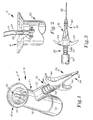
Figure 1 is a perspective view of a draw off embodiment of the fluid dispenser apparatus of the present invention used to draw off and administer fluid from a bulk container. -
Figure 2 is a view, partially in cross-section, of a hose attached to the fluid stem of the draw off embodiment ofFigure 1 . -
Figure 3 is a side view of a needle attached to a trigger member. -
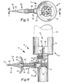
Figure 4 is a side view of a spike embodiment of the fluid dispenser apparatus of the present invention used to administer fluid from a sealed end pharmaceutical bottle. -
Figure 5 is a top view of the spike embodiment ofFigure 4 . -
Figure 6 is a cross section of the spike embodiment taken along line 6-6 ofFigure 5 . -
Figure 7 is a side view, partially in cross-section, of a threaded bottle mount embodiment of the fluid dispenser apparatus of the present invention used to administer liquid from a wide-mouth threaded container. -
Figure 8 is a rear view of the threaded bottle mount embodiment ofFigure 7 . -
Figure 9 is a top view of the threaded bottle mount embodiment ofFigure 7 . -
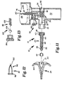
Figure 10 is a side view, partially exploded and partially in cross-section for clarity, of the threaded bottle mount embodiment ofFigure 7 . -
Figure 11 is a side view, partially exploded and partially in cross-section for clarity, of the spike embodiment ofFigure 5 . -
Figure 12 is a side view of the elastomeric valve used as the air valve inFigure 11 . -
Figure 13 is a side view of a check valve that could alternatively be used as the air valve inFigure 11 . -
Figures 1-11 show examples of three preferred embodiments of thedispenser apparatus 10.Figures 1-2 illustrate a "Draw Off"embodiment 12 of thedispenser 10,Figures 4-6 , and 11 illustrate a "Spike"embodiment 14 of thedispenser 10, andFigures 7-10 illustrate a "Threaded Bottle Mount"embodiment 16 of the dispenser. Thedispenser 10 of all three embodiments is described below first in terms of its major structural elements and then in terms of its secondary structural and/or functional elements which cooperate to economically and ergonomically dispense fixed doses of fluid accurately and rapidly. The differences for each embodiment will be described in detail after the general discussion of thedispenser 10. - As generally shown in
Figures 1 ,4 ,7 ,10-11 thedispenser 10 includes aconnection member 18, abody member 20, apiston member 22, and atrigger member 24. Theconnection member 18 provides fluid communication between thedispenser 10 and a fluid source orfluid source container 26. Theconnection member 18 is constructed to have afluid ingress channel 28 through which the fluid flows fromfluid source container 26 and into thebody member 20. - The
body member 20 is constructed to have afluid communication channel 30, adose cylinder 32, and adose valve 34. Thefluid communication channel 30 is communicatively connected to thefluid ingress channel 28 and to thedose cylinder 32 so that fluid flows from the fluid ingress channel, through thefluid communication channel 30, and into thedose cylinder 32. Thedose cylinder 32 forms a cylinder for the compression and expansion stroke of thepiston member 22. Thedose cylinder 32 andpiston member 22 are related to each other in such a way as to have a predeterminedvolume 36 or swept volume that corresponds to the desired dose of the dispensed fluid. As shown inFigures 10-11 thisvolume 36 may be varied by varying the width of theshoulder 35 integrally formed in thedose cylinder 32; or alternatively, it may be varied by interchanging theremovable block 37 with one with a different width. Furthermore, aremovable piston member 22 could be replaced with apiston member 22 that provides a different swept volume. As shown inFigures 6 ,10-11 thedose valve 34 is positioned between thefluid communication channel 30 and thedose cylinder 32. Thedose valve 34 permits fluid to flow only in the direction from thefluid communication channel 30 to thedose cylinder 32 when the expansion stroke of thepiston member 22 causes a pressure differential between thefluid communication channel 30 and thedose cylinder 32, but will not permit fluid to flow from thedose cylinder 32 to thecommunication channel 30 during a compression stroke. As shown in greater detail inFigures 10 and11 , a one-way helix valve 90 is used as thedose valve 34. Thehelix valve 90 includes ahelical portion 92 that fits within thefluid communication channel 30 and avalve stem 94 moveably positioned within thehelical portion 92 such that it will form a seal when the pressure in thedose cylinder 32 is greater than the pressure in thecommunication channel 30. It is anticipated that other pressure-sensitive, one-way valves could be used as thedose valve 34. - As shown in
Figures 6 and7 , thepiston member 22 generally includes apiston head 38, anannular gasket 40, apiston valve 42, and apiston rod 44. Afluid egress channel 46 extends through thepiston head 38 andpiston rod 44 to adistal end 46 of thepiston rod 44. Thepiston head 38 has an outer periphery sized and shaped to have a functionally sealing fit with theinterior surface 54 of thedose cylinder 32. The piston head has acircumferential groove 56 about its outer periphery sized to receive theannular gasket 40. Thegasket 40 provides the functionally sealing fit with theinterior surface 54 of thedose cylinder 32. Thepiston valve 42 is positioned at thedistal end 46 of thepiston member 22. As shown in more detail inFigures 10 and11 , thepiston valve 42 has a form of an elastomeric band that provides a one-way seal around theoutlet ports 96 of thefluid egress channel 48. Thepiston valve 42 permits fluid to only flow out of thefluid egress channel 48 when the compression stroke of thepiston member 22 increases the pressure in thefluid egress channel 48. Thepiston member 22 or plunger provides a non-conventional delivery system for the fluid. Whereas conventional syringes expel fluid through their barrel end, the present invention expels fluid through its plunger. - The
trigger member 24 is attached to thedistal end 48 of thepiston rod 44. Anozzle channel 50 within thetrigger member 24 is communicatively attached to thefluid egress channel 46 and extends through thenozzle portion 52 of thetrigger member 24. As required by the pharmaceutical dispensing application, thenozzle portion 52 of any of the embodiments may have the form of anoral tip 58 for oral or intranasal applications, or it may take the form of aninjectable tip 60, such as a Luer slip or Luer lock tip, that can be fitted with aneedle 62 for injectable applications. Thebody member 20 may also include a needle storage holder orstorage container 72. Thetrigger member 24 is formed withgrips 64 that interface with an operator's fingers when thebody member 20 is placed in the operator's palm. An operator squeezes his or her fingers to pull thetrigger member 24 toward thebody member 20. This action compresses thepiston member 22 within thedose cylinder 32 and expels the dose volume of the fluid through thefluid egress channel 48, thepiston valve 42, thenozzle channel 50, and out of thenozzle portion 52. - A
spring 66 surrounds thepiston rod 44 and extends between thetrigger member 24 and thedose cylinder 34. Thespring 64 biases thepiston member 22 in an extended position and, upon the operator's release of thetrigger member 24, will automatically produce the expansion stroke by returning thepiston member 22 to the extended position. The expansion stroke draws the dose volume of fluid into thedose cylinder 32. - The figures show the
piston member 22 and thetrigger member 24 extending from thebody member 20 at a near right angle. However, thepiston member 22 andtrigger member 24 could be aligned with thebody member 20 such that it is in the general location of the shown position for thestorage container 72. - Many elements of the
dispenser 10 are manufactured from a clear or relatively transparent plastic material. The body member and connection member are generally molded as a unitary piece of plastic, as is the piston member. This material provides a strong, light weight andinexpensive dispenser 10. Furthermore, the transparent nature of the material allows an operator to visually monitor the device in operation. Thedispenser 10 is manufactured to be easily cleaned, sanitized and lubricated. However, it is also inexpensive enough to be considered semi-disposable; that is, it can be disposed after an application or a series of applications as warranted by the circumstances. - The
Draw Off embodiment 12 shown inFigure 1 has aninjectable tip 60 for receiving aneedle 62 as shown inFigure 3 . Thebody member 20 is constructed to have astorage container 72 designed to store spare and / or used needles. Thestorage container 72 is closed with aremovable cap 74, plug or other closure. TheDraw Off embodiment 12 is designed to dispense fluid from flexible or rigid bulk fluid source containers of various sizes and shapes. Theconnection member 18 is constructed with a fluid stem 68 that contains thefluid ingress channel 28. The fluid stem 68 is designed to receive ahose 70 that provides a communicative path between the external fluid source container and thefluid ingress channel 28. Theconnection member 18 also hascontinuous side walls 70, which in this embodiment are flange-like. - The
Spike embodiment 14 shown inFigures 4-6 is shown to have aninjectable tip 60 for receiving aneedle 62 as shown inFigure 3 . Thebody member 20 is constructed to have astorage container 72 designed to store spare and / or used needles. Thestorage container 72 is closed with aremovable cap 74, plug or other closure. TheSpike embodiment 14 is designed to directly mount a vile or other sealed endfluid source container 26 onto thedispenser 10. Theconnection member 18 is constructed with aspike 76 designed to puncture through the sealed end of a flexible or rigidfluid source container 26, and with acontinuous side wall 70 designed to support thefluid source container 26 in a mounted position. The Spike embodiment includes anair intake system 78 that replaces fluid drawn from thefluid source container 26 with ambient air as an automatic venting function. Theair intake system 78 provides for smoother fluid flow and easier operation by equalizing the pressure between the interior and exterior of thefluid source container 26. Theair intake system 78 generally comprises avent channel 80, anair valve 82, and anair intake port 84. Thevent channel 80 provides the means for transferring ambient air from theair intake port 84, through theair valve 82, and into thefluid source container 26. A pressure differential is created between the outside and inside of thecontainer 26 when fluid is dispensed. Theair valve 82 allows air to enter thecontainer 26 when there is a pressure differential, and it prevents fluid from flowing out of thecontainer 26 thevent channel 80. Thespike 76 contains both thefluid ingress channel 28 and thevent channel 80. Theair intake system 78, or vent system, can be cleaned without removing thecontainer 26 by injecting air from a syringe into theair intake port 84. - As shown in
Figures 11, 12 and 13 , theair valve 82 may use different types of one-way pressure sensitive valves.Figures 11 and 12 show anair valve 82 that uses a wedge-like,elastomeric valve 96. Theelastomeric valve 96 has a generally cylindrical shapedproximate end 98 and adistal end 100. Thedistal end 100 has a slit that is normally closed, thus preventing fluid from flowing out theair intake system 78, but opens relatively easily to allow air to flow into thecontainer 26. Alternatively as shown inFigure 13 , acheck valve 102 containing acheck ball 104 andspring 106 could be use to provide the one-way valve function. - The Threaded
Bottle Mount embodiment 16 shown inFigures 7-10 has anoral tip 58. This embodiment is designed to directly attach a bottle orfluid source container 26 onto thedispenser 10 by screwing it onto theconnection member 18. Theconnection member 18 is constructed to have a form similar to an inverted bottle cap, includingcontinuous side walls 70 having interiorly disposedthreads 86 designed to mate with exteriorly disposedthreads 88 on thecontainer 26, such as a wide mouth threaded container. Theconnection member 18 has abottom surface 71 disposed between and joined to theside walls 70.Figure 10 shows theconnection member 18 exploded as a separate element for clarity. However, theconnection member 18 is typically molded with thebody member 20 as a unitary piece. Thefluid ingress channel 28 is formed by an aperture in thebottom surface 71. The Threaded Bottle Mount embodiment includes anair intake system 78 that replaces fluid drawn from thefluid source container 26 with ambient air as an automatic venting function. Theair intake system 78 provides for smoother fluid flow easier operation by equalizing the pressure between the interior and exterior of thefluid source container 26, which prevents the fluid from being suctioned back into thecontainer 26 and possibly contaminating the medicinal source. Theair intake system 78 generally comprises avent channel 80, anair valve 82, and anair intake port 84. Thevent channel 80 provides the means for transferring ambient air from theair intake port 84, through theair valve 82, and into thefluid source container 26. A pressure differential is created between the inside and outside of thecontainer 26 when fluid is dispensed. Theair valve 82 allows air to enter thecontainer 26 when there is a pressure differential, but it prevents fluid from flowing out of thecontainer 26 through thevent channel 80. Theair valve 82 shown inFigure 10 is ahelix valve 90 that contains ahelical portion 92 and avalve stem 94. It is anticipated that other one-way, pressure sensitive valves could be used. Theconnection member 18 is constructed to contain thevent channel 80. - The descriptions above and the accompanying drawings should be interpreted in the illustrative and not the limited sense. While the invention has been disclosed in connection with the preferred embodiment or embodiments thereof, it should be understood that there may be other embodiments which fall within the scope of the invention as defined by the following claims.
Claims (21)
- A fluid dispenser comprising:(a) a body member (20) having a fluid communication channel (30) and a dose cylinder (32) of a predetermined volume, said fluid communication channel (30) being communicatively joined with said dose cylinder (32);(b) a fluid egress conduit (46) communicatively connected to a dose cylinder (32);(c) a dose valve (34) positioned and arranged to govern fluid flow from said fluid communication channel (30) to said dose cylinder (32);(d) a piston valve (42) positioned and arranged to govern fluid flow out of said fluid egress conduit (46);(e) a piston member (22) having a piston head (38), a distal end (48) and a piston rod (44) connecting said piston head (38) to said distal end (48), said piston head (38) being sealingly fit within said dose cylinder (32); and(f) a trigger member (24) attached to said distal end (40) of said piston member (22), whereby said fluid dispenser, when primed, draws a dose of fluid through said communication channel (30) into said dose cylinder (32) during a complete expansion stroke of said piston member (38) and expels said predetermined amount of fluid from said dose cylinder (32) through said fluid egress conduit (46) during a complete compression stroke of said piston member (38); and characterised by a needle storage holder (72).
- The fluid dispenser of Claim 1, wherein said body member (20) has a storage container, said storage container forming said needle storage holder (72).
- The fluid dispenser of Claim 1, wherein said predetermined volume of said dose cylinder (32) is fixed.
- The fluid dispenser of Claim 1, wherein said predetermined volume of said dose cylinder (32) is adjustable.
- The fluid dispenser of Claim 4, further including a removable block within said dose cylinder (32).
- The fluid dispenser of Claim 4, wherein said piston member (22) is a removable plunger, said plunger having a head of a predetermined size corresponding to a desired dose volume.
- The fluid dispenser of Claim 1, wherein said trigger member (24) includes at least one grip formed to interface with at least one finger of the user, whereby said body member (20) rests in the palm of the user's hand and the user's finger squeezes said grip toward said body member (20) to provide force for said compression stroke of said piston member (22).
- The fluid dispenser of Claim 1, wherein said trigger member (24) includes a nozzle portion and a nozzle channel communicatively connected to said fluid egress conduit.
- The fluid dispenser of Claim 1, wherein said piston member (22) has a fluid egress channel extending through said piston head (38) and said piston rod (44) to said distal end, and said fluid egress channel (46) forms said fluid egress conduit.
- The fluid dispenser of Claim 9, wherein said trigger member (24) includes a nozzle portion and a nozzle channel communicatively connected to said fluid egress channel.
- The fluid dispenser of Claim 1, wherein said piston member (22) is biased in an extended position by a spring, said spring being positioned around said piston member (22) and in between said trigger member (24) and said dose cylinder (32), whereby said spring provides force for said expansion stroke of said piston member.
- The fluid dispenser of Claim 1, wherein said piston head (38) has a circumference, a groove formed around said circumference, and an annular gasket placed within said groove, said gasket providing said fit within said dose cylinder.
- The fluid dispenser of Claim 1, further comprising a connection member (81) having a fluid egress channel (28) communicatively connected to a fluid source container (26) and to said fluid communication channel (30), said fluid source container (26) having an interior and an exterior.
- The fluid dispenser of Claim 13, wherein said connection member (18) has a continuous side wall, said continuous side wall has a predetermined size and shape for receiving and supporting a fluid source container (26).
- The fluid dispenser of Claim 14, wherein said connection member (18) has a continuous side wall and a bottom surface joined with said side wall, said continuous side wall having interior threads, said fluid source container (26) having external threads, said fluid source container (26) being connected to said connection member (18) by mating said interior threads with said external threads, said bottom surface having an aperture which forms said fluid ingress channel.
- The fluid dispenser of Claim 13, wherein said connection member (18) has a fluid stem, said fluid ingress channel being contained within said fluid stem.
- The fluid dispenser of Claim 16, wherein said fluid stem is formed to receive a hose for drawing fluid from said fluid source container, said hose being communicatively connected between said fluid source container and said fluid stem.
- The fluid dispenser of Claim 16, wherein said fluid stem is a spike designed to penetrate said fluid source container when said fluid source container is directly mounted onto said spike.
- The fluid dispenser of Claim 18, further including an air intake system to equalise pressure between the interior and the exterior of said fluid source container (26) when fluid is drawn out of said fluid source container (26), said air intake system including an air intake port, a vent channel communicatively connected from said air intake port to said fluid source, and an air valve designed to allow ambient air to flow through said vent channel into said fluid source container upon a pressure differential between the interior and the exterior of said fluid source container and to prevent fluid from flowing out of said fluid source container through said vent channel, wherein said spike further includes a vent channel.
- The fluid dispenser of Claim 13, further including an air intake system to equalise pressure between the interior and exterior of said fluid source container (26) when fluid is drawn out of said fluid source container (26).
- The fluid dispenser of Claim 20, wherein said air intake system includes an air intake port, a vent channel communicatively connected from said air intake port to said fluid source, and an air valve designed to allow ambient air to flow through said vent channel into said fluid source container (26) upon a pressure differential between the exterior and the interior of said fluid source container (26) and to prevent fluid from flowing out of said fluid source container (26) through said vent channel.
Applications Claiming Priority (3)
| Application Number | Priority Date | Filing Date | Title |
|---|---|---|---|
| US1924996P | 1996-06-07 | 1996-06-07 | |
| US19249P | 1996-06-07 | ||
| PCT/US1997/009951 WO1997046479A1 (en) | 1996-06-07 | 1997-06-06 | Fluid dispenser apparatus |
Publications (3)
| Publication Number | Publication Date |
|---|---|
| EP1015382A1 EP1015382A1 (en) | 2000-07-05 |
| EP1015382A4 EP1015382A4 (en) | 2006-05-17 |
| EP1015382B1 true EP1015382B1 (en) | 2009-11-18 |
Family
ID=21792217
Family Applications (1)
| Application Number | Title | Priority Date | Filing Date |
|---|---|---|---|
| EP97929868A Expired - Lifetime EP1015382B1 (en) | 1996-06-07 | 1997-06-06 | Fluid dispenser apparatus |
Country Status (6)
| Country | Link |
|---|---|
| US (1) | US5934510A (en) |
| EP (1) | EP1015382B1 (en) |
| AU (1) | AU723196B2 (en) |
| DE (1) | DE69739667D1 (en) |
| DK (1) | DK1015382T3 (en) |
| WO (1) | WO1997046479A1 (en) |
Families Citing this family (36)
| Publication number | Priority date | Publication date | Assignee | Title |
|---|---|---|---|---|
| DE19615422A1 (en) | 1996-04-19 | 1997-11-20 | Boehringer Ingelheim Kg | Two-chamber cartridge for propellant-free MDIs |
| US6364170B1 (en) * | 1996-06-07 | 2002-04-02 | Mark L. Anderson | Fluid dispenser apparatus |
| US6253961B1 (en) * | 1997-06-06 | 2001-07-03 | Mark L. Anderson | Fluid dispenser apparatus |
| US6223746B1 (en) * | 1998-02-12 | 2001-05-01 | Iep Pharmaceutical Devices Inc. | Metered dose inhaler pump |
| US6158431A (en) * | 1998-02-13 | 2000-12-12 | Tsi Incorporated | Portable systems and methods for delivery of therapeutic material to the pulmonary system |
| DE19840992A1 (en) * | 1998-09-08 | 2000-03-09 | Disetronic Licensing Ag | Pressure monitoring of a product fluid to be administered in doses during an infusion or injection |
| ATE251499T1 (en) | 1999-08-05 | 2003-10-15 | Procter & Gamble | DEVICE WITH A CONNECTION SYSTEM |
| DE69910053T2 (en) * | 1999-12-01 | 2004-04-15 | The Procter & Gamble Company, Cincinnati | Device for product delivery |
| AU2001263098A1 (en) | 2000-05-12 | 2001-11-26 | Iep Pharmaceutical Devices, Inc. | Powder/liquid metering valve |
| US8562583B2 (en) | 2002-03-26 | 2013-10-22 | Carmel Pharma Ab | Method and assembly for fluid transfer and drug containment in an infusion system |
| US7867215B2 (en) | 2002-04-17 | 2011-01-11 | Carmel Pharma Ab | Method and device for fluid transfer in an infusion system |
| SE523001C2 (en) * | 2002-07-09 | 2004-03-23 | Carmel Pharma Ab | Coupling component for transmitting medical substances, comprises connecting mechanism for releasable connection to second coupling component having further channel for creating coupling, where connecting mechanism is thread |
| JP5148107B2 (en) | 2003-01-21 | 2013-02-20 | カルメル ファルマ アクチボラゲット | Needle for piercing the membrane |
| US7165357B2 (en) | 2003-06-18 | 2007-01-23 | Philip David Burgess | Japanese knotweed injector system |
| WO2007069907A1 (en) * | 2005-12-12 | 2007-06-21 | Ge Healthcare As | Spike-accommodating container holder |
| US7942860B2 (en) | 2007-03-16 | 2011-05-17 | Carmel Pharma Ab | Piercing member protection device |
| US7975733B2 (en) | 2007-05-08 | 2011-07-12 | Carmel Pharma Ab | Fluid transfer device |
| US8622985B2 (en) | 2007-06-13 | 2014-01-07 | Carmel Pharma Ab | Arrangement for use with a medical device |
| US8029747B2 (en) | 2007-06-13 | 2011-10-04 | Carmel Pharma Ab | Pressure equalizing device, receptacle and method |
| US8657803B2 (en) | 2007-06-13 | 2014-02-25 | Carmel Pharma Ab | Device for providing fluid to a receptacle |
| US10398834B2 (en) | 2007-08-30 | 2019-09-03 | Carmel Pharma Ab | Device, sealing member and fluid container |
| US8287513B2 (en) | 2007-09-11 | 2012-10-16 | Carmel Pharma Ab | Piercing member protection device |
| US8075550B2 (en) | 2008-07-01 | 2011-12-13 | Carmel Pharma Ab | Piercing member protection device |
| US8523838B2 (en) | 2008-12-15 | 2013-09-03 | Carmel Pharma Ab | Connector device |
| US8790330B2 (en) | 2008-12-15 | 2014-07-29 | Carmel Pharma Ab | Connection arrangement and method for connecting a medical device to the improved connection arrangement |
| US8353859B2 (en) * | 2009-04-27 | 2013-01-15 | Animal Innovations, Inc. | Injection syringe plunger valve assembly |
| US8480646B2 (en) | 2009-11-20 | 2013-07-09 | Carmel Pharma Ab | Medical device connector |
| USD637713S1 (en) | 2009-11-20 | 2011-05-10 | Carmel Pharma Ab | Medical device adaptor |
| US8807133B2 (en) * | 2010-01-19 | 2014-08-19 | Mark Anderson | Resuscitator and aspirator technology |
| US9168203B2 (en) | 2010-05-21 | 2015-10-27 | Carmel Pharma Ab | Connectors for fluid containers |
| US8162013B2 (en) | 2010-05-21 | 2012-04-24 | Tobias Rosenquist | Connectors for fluid containers |
| DK2486945T3 (en) * | 2011-02-11 | 2014-04-22 | Oro Clean Chemie Ag | Method and device for cleaning medical instruments |
| US10413662B2 (en) * | 2015-05-14 | 2019-09-17 | Carefusion 303, Inc. | Priming apparatus and method |
| CH716306A2 (en) * | 2019-06-11 | 2020-12-15 | Elc Ceratec Gmbh | Device for the metered dispensing of a liquid from a container and spray applicator with such a device. |
| US11596269B2 (en) | 2020-01-21 | 2023-03-07 | Kerrick Patterson | Liquid dispensing container and housing assembly |
| USD1000883S1 (en) | 2020-08-14 | 2023-10-10 | Brad A. Reid | Liquid and cup dispenser |
Family Cites Families (30)
| Publication number | Priority date | Publication date | Assignee | Title |
|---|---|---|---|---|
| US1496126A (en) * | 1922-06-09 | 1924-06-03 | Joseph W Livingstone | Syringe |
| US2086467A (en) * | 1936-08-26 | 1937-07-06 | John H Bryan | Pump attachment |
| US2753079A (en) * | 1953-05-04 | 1956-07-03 | Knickerbocker Plastic Co Inc | Water gun |
| US2825334A (en) * | 1953-08-07 | 1958-03-04 | Sr John Leo Kas | Hypodermic syringe for livestock |
| US3215171A (en) * | 1962-09-19 | 1965-11-02 | Barmar Products Co | Medicine dropper construction |
| US3209951A (en) * | 1963-06-12 | 1965-10-05 | Raymond E Greene | Attachable oil pump |
| US3228564A (en) * | 1963-12-11 | 1966-01-11 | John L Olson | Dispensing device |
| US3526225A (en) * | 1967-03-31 | 1970-09-01 | Tokyo Sokuhan Kk | Jet-type hypodermic injection device |
| US3604592A (en) * | 1970-01-09 | 1971-09-14 | Spartan International Corp | Combination cup and liquid dispenser |
| US3827601A (en) * | 1973-03-23 | 1974-08-06 | J Magrath | Hand powered liquid dispenser of the metering type |
| US3952918A (en) * | 1974-03-18 | 1976-04-27 | Highland Laboratories | Fluid dispenser apparatus |
| US3952919A (en) * | 1975-07-03 | 1976-04-27 | Joseph M. Magrath | Reservoir adapter for liquid dispenser |
| US4185755A (en) * | 1977-06-10 | 1980-01-29 | Bayer Aktiengesellschaft | Adjustable dose pistol-type applicator |
| GB2111132B (en) * | 1981-12-01 | 1985-09-11 | English Glass Co Ltd | Dispenser pump |
| ATE34921T1 (en) * | 1982-10-08 | 1988-06-15 | Fisons Plc | ADJUSTABLE DOSE INJECTION GUN. |
| US4826050A (en) * | 1984-11-28 | 1989-05-02 | Murphy Allan P | Spraying and dosing apparatus |
| US4678107A (en) | 1985-08-02 | 1987-07-07 | Mark L. Anderson | Dripless dispenser for liquids and viscous fluids |
| US4852772A (en) | 1987-12-07 | 1989-08-01 | Genesis Industries, Incorporated | Dispenser for viscous fluids |
| US4923448A (en) * | 1988-12-06 | 1990-05-08 | Mark Anderson | Syringe with spray nozzle tip |
| US4923096A (en) | 1989-01-09 | 1990-05-08 | Mark L. Anderson | Dripless automatic syringe for dispensing fluids |
| US4981472B2 (en) | 1989-11-20 | 1996-12-24 | Mark Anderson | Cannula assembly for syringe |
| US4995867A (en) * | 1990-01-24 | 1991-02-26 | Zollinger Eugene A | Aural medication dispenser |
| US5217442A (en) * | 1990-09-28 | 1993-06-08 | Minimed Technologies | Aspiration and refill kit for a medication infusion pump |
| US5190191A (en) * | 1991-03-13 | 1993-03-02 | Reyman Mark E | Apparatus for measured and unmeasured dispensing of viscous fluids |
| US5176645A (en) * | 1991-05-01 | 1993-01-05 | Diana Corporation | Pneumatic, modular device for dispensing medication to animals |
| GB9220580D0 (en) * | 1992-09-30 | 1992-11-11 | Dent Hugh R | Improvements in or relating to gas powered applicators |
| JP2591744Y2 (en) * | 1993-01-20 | 1999-03-10 | ノードソン株式会社 | Dispenser for liquid discharge with liquid enclosing cartridge storage case |
| US5344409A (en) | 1993-06-14 | 1994-09-06 | Genesis Industries Inc. | Syringe latch |
| FR2709287B1 (en) * | 1993-08-26 | 1995-11-17 | Suppo Steril Laboratoires | Case for dosing accessories fixed on a bottle. |
| GB9405891D0 (en) * | 1994-03-24 | 1994-05-11 | English Glass Company The Limi | Dispenser pumps |
-
1997
- 1997-06-06 WO PCT/US1997/009951 patent/WO1997046479A1/en active Application Filing
- 1997-06-06 DK DK97929868.4T patent/DK1015382T3/en active
- 1997-06-06 DE DE69739667T patent/DE69739667D1/en not_active Expired - Lifetime
- 1997-06-06 US US08/870,918 patent/US5934510A/en not_active Expired - Lifetime
- 1997-06-06 AU AU33828/97A patent/AU723196B2/en not_active Ceased
- 1997-06-06 EP EP97929868A patent/EP1015382B1/en not_active Expired - Lifetime
Also Published As
| Publication number | Publication date |
|---|---|
| AU723196B2 (en) | 2000-08-17 |
| WO1997046479A1 (en) | 1997-12-11 |
| DE69739667D1 (en) | 2009-12-31 |
| DK1015382T3 (en) | 2010-03-08 |
| US5934510A (en) | 1999-08-10 |
| AU3382897A (en) | 1998-01-05 |
| EP1015382A4 (en) | 2006-05-17 |
| EP1015382A1 (en) | 2000-07-05 |
Similar Documents
| Publication | Publication Date | Title |
|---|---|---|
| EP1015382B1 (en) | Fluid dispenser apparatus | |
| US6364170B1 (en) | Fluid dispenser apparatus | |
| US7726520B2 (en) | Metered dispenser with feed-containing piston drive mechanism | |
| US3827601A (en) | Hand powered liquid dispenser of the metering type | |
| AU755781B2 (en) | Improved marking syringe | |
| US4426024A (en) | Device for dispensing fluid | |
| US5931347A (en) | Dispenser unit for viscous substances | |
| US6561389B1 (en) | Dispenser apparatus for medical grade ultrasound gel | |
| SK280177B6 (en) | Dispenser for manual discharge of a single dose | |
| US8556128B2 (en) | Dispensing channel pump | |
| SE447340B (en) | SYRINGE | |
| CN102036703A (en) | Veterinary syringe for multiple injections | |
| US5037399A (en) | Apparatus for the administration of medications to animals | |
| US20110009822A1 (en) | Dispenser for local anaesthetics and other liquids | |
| US6253961B1 (en) | Fluid dispenser apparatus | |
| US20070225658A1 (en) | Unit Dose Delivery Systems | |
| US4098276A (en) | Syringe pumping handle grip and method of assembling same | |
| US5102398A (en) | Plungerless syringe | |
| CN115003249A (en) | Powder product dispensing device | |
| GB2203345A (en) | Dispenser for vaginal creams | |
| CA2101049A1 (en) | Dosing apparatus for sterile and/or pharmaceutical solutions | |
| JP2023551060A (en) | Devices for delivering doses of ophthalmic liquid sprays and pumps suitable for devices for delivering ophthalmic liquid sprays | |
| CN115003248A (en) | Powder product dispensing device | |
| CN111094147A (en) | Self-sealing airless metering distributor |
Legal Events
| Date | Code | Title | Description |
|---|---|---|---|
| PUAI | Public reference made under article 153(3) epc to a published international application that has entered the european phase |
Free format text: ORIGINAL CODE: 0009012 |
|
| 17P | Request for examination filed |
Effective date: 19981120 |
|
| AK | Designated contracting states |
Kind code of ref document: A1 Designated state(s): DE DK FR GB NL |
|
| A4 | Supplementary search report drawn up and despatched |
Effective date: 20060403 |
|
| 17Q | First examination report despatched |
Effective date: 20060717 |
|
| GRAP | Despatch of communication of intention to grant a patent |
Free format text: ORIGINAL CODE: EPIDOSNIGR1 |
|
| GRAS | Grant fee paid |
Free format text: ORIGINAL CODE: EPIDOSNIGR3 |
|
| GRAA | (expected) grant |
Free format text: ORIGINAL CODE: 0009210 |
|
| AK | Designated contracting states |
Kind code of ref document: B1 Designated state(s): DE DK FR GB NL |
|
| REG | Reference to a national code |
Ref country code: GB Ref legal event code: FG4D |
|
| REF | Corresponds to: |
Ref document number: 69739667 Country of ref document: DE Date of ref document: 20091231 Kind code of ref document: P |
|
| REG | Reference to a national code |
Ref country code: DK Ref legal event code: T3 |
|
| PGFP | Annual fee paid to national office [announced via postgrant information from national office to epo] |
Ref country code: DK Payment date: 20100610 Year of fee payment: 14 |
|
| PLBE | No opposition filed within time limit |
Free format text: ORIGINAL CODE: 0009261 |
|
| STAA | Information on the status of an ep patent application or granted ep patent |
Free format text: STATUS: NO OPPOSITION FILED WITHIN TIME LIMIT |
|
| 26N | No opposition filed |
Effective date: 20100819 |
|
| PGFP | Annual fee paid to national office [announced via postgrant information from national office to epo] |
Ref country code: NL Payment date: 20100603 Year of fee payment: 14 |
|
| PGFP | Annual fee paid to national office [announced via postgrant information from national office to epo] |
Ref country code: FR Payment date: 20110621 Year of fee payment: 15 |
|
| PGFP | Annual fee paid to national office [announced via postgrant information from national office to epo] |
Ref country code: GB Payment date: 20110601 Year of fee payment: 15 |
|
| PGFP | Annual fee paid to national office [announced via postgrant information from national office to epo] |
Ref country code: DE Payment date: 20110601 Year of fee payment: 15 |
|
| REG | Reference to a national code |
Ref country code: NL Ref legal event code: V1 Effective date: 20120101 |
|
| REG | Reference to a national code |
Ref country code: DK Ref legal event code: EBP |
|
| PG25 | Lapsed in a contracting state [announced via postgrant information from national office to epo] |
Ref country code: NL Free format text: LAPSE BECAUSE OF NON-PAYMENT OF DUE FEES Effective date: 20120101 |
|
| PG25 | Lapsed in a contracting state [announced via postgrant information from national office to epo] |
Ref country code: DK Free format text: LAPSE BECAUSE OF NON-PAYMENT OF DUE FEES Effective date: 20110630 |
|
| GBPC | Gb: european patent ceased through non-payment of renewal fee |
Effective date: 20120606 |
|
| REG | Reference to a national code |
Ref country code: FR Ref legal event code: ST Effective date: 20130228 |
|
| PG25 | Lapsed in a contracting state [announced via postgrant information from national office to epo] |
Ref country code: DE Free format text: LAPSE BECAUSE OF NON-PAYMENT OF DUE FEES Effective date: 20130101 Ref country code: FR Free format text: LAPSE BECAUSE OF NON-PAYMENT OF DUE FEES Effective date: 20120702 Ref country code: GB Free format text: LAPSE BECAUSE OF NON-PAYMENT OF DUE FEES Effective date: 20120606 |
|
| REG | Reference to a national code |
Ref country code: DE Ref legal event code: R119 Ref document number: 69739667 Country of ref document: DE Effective date: 20130101 |