EP1018827B1 - Synchronisation structure for OFDM system - Google Patents
Synchronisation structure for OFDM system Download PDFInfo
- Publication number
- EP1018827B1 EP1018827B1 EP99103379A EP99103379A EP1018827B1 EP 1018827 B1 EP1018827 B1 EP 1018827B1 EP 99103379 A EP99103379 A EP 99103379A EP 99103379 A EP99103379 A EP 99103379A EP 1018827 B1 EP1018827 B1 EP 1018827B1
- Authority
- EP
- European Patent Office
- Prior art keywords
- symbols
- ofdm
- time domain
- synchronization
- subcarriers
- Prior art date
- Legal status (The legal status is an assumption and is not a legal conclusion. Google has not performed a legal analysis and makes no representation as to the accuracy of the status listed.)
- Expired - Lifetime
Links
Images


Classifications
-
- H—ELECTRICITY
- H04—ELECTRIC COMMUNICATION TECHNIQUE
- H04L—TRANSMISSION OF DIGITAL INFORMATION, e.g. TELEGRAPHIC COMMUNICATION
- H04L27/00—Modulated-carrier systems
- H04L27/26—Systems using multi-frequency codes
-
- H—ELECTRICITY
- H04—ELECTRIC COMMUNICATION TECHNIQUE
- H04L—TRANSMISSION OF DIGITAL INFORMATION, e.g. TELEGRAPHIC COMMUNICATION
- H04L25/00—Baseband systems
- H04L25/02—Details ; arrangements for supplying electrical power along data transmission lines
- H04L25/03—Shaping networks in transmitter or receiver, e.g. adaptive shaping networks
- H04L25/03006—Arrangements for removing intersymbol interference
- H04L25/03343—Arrangements at the transmitter end
-
- H—ELECTRICITY
- H04—ELECTRIC COMMUNICATION TECHNIQUE
- H04L—TRANSMISSION OF DIGITAL INFORMATION, e.g. TELEGRAPHIC COMMUNICATION
- H04L27/00—Modulated-carrier systems
- H04L27/26—Systems using multi-frequency codes
- H04L27/2601—Multicarrier modulation systems
- H04L27/2602—Signal structure
- H04L27/261—Details of reference signals
- H04L27/2613—Structure of the reference signals
-
- H—ELECTRICITY
- H04—ELECTRIC COMMUNICATION TECHNIQUE
- H04L—TRANSMISSION OF DIGITAL INFORMATION, e.g. TELEGRAPHIC COMMUNICATION
- H04L27/00—Modulated-carrier systems
- H04L27/26—Systems using multi-frequency codes
- H04L27/2601—Multicarrier modulation systems
- H04L27/2614—Peak power aspects
- H04L27/262—Reduction thereof by selection of pilot symbols
-
- H—ELECTRICITY
- H04—ELECTRIC COMMUNICATION TECHNIQUE
- H04L—TRANSMISSION OF DIGITAL INFORMATION, e.g. TELEGRAPHIC COMMUNICATION
- H04L5/00—Arrangements affording multiple use of the transmission path
- H04L5/0001—Arrangements for dividing the transmission path
- H04L5/0003—Two-dimensional division
- H04L5/0005—Time-frequency
- H04L5/0007—Time-frequency the frequencies being orthogonal, e.g. OFDM(A), DMT
-
- H—ELECTRICITY
- H04—ELECTRIC COMMUNICATION TECHNIQUE
- H04L—TRANSMISSION OF DIGITAL INFORMATION, e.g. TELEGRAPHIC COMMUNICATION
- H04L5/00—Arrangements affording multiple use of the transmission path
- H04L5/003—Arrangements for allocating sub-channels of the transmission path
- H04L5/0042—Arrangements for allocating sub-channels of the transmission path intra-user or intra-terminal allocation
-
- H—ELECTRICITY
- H04—ELECTRIC COMMUNICATION TECHNIQUE
- H04L—TRANSMISSION OF DIGITAL INFORMATION, e.g. TELEGRAPHIC COMMUNICATION
- H04L27/00—Modulated-carrier systems
- H04L27/26—Systems using multi-frequency codes
- H04L27/2601—Multicarrier modulation systems
- H04L27/2647—Arrangements specific to the receiver only
- H04L27/2655—Synchronisation arrangements
- H04L27/2657—Carrier synchronisation
-
- H—ELECTRICITY
- H04—ELECTRIC COMMUNICATION TECHNIQUE
- H04L—TRANSMISSION OF DIGITAL INFORMATION, e.g. TELEGRAPHIC COMMUNICATION
- H04L27/00—Modulated-carrier systems
- H04L27/26—Systems using multi-frequency codes
- H04L27/2601—Multicarrier modulation systems
- H04L27/2647—Arrangements specific to the receiver only
- H04L27/2655—Synchronisation arrangements
- H04L27/2662—Symbol synchronisation
Definitions
- the present invention relates to a method for generating synchronization bursts for OFDM transmission systems, an OFDM transmitter, a mobile communications device comprising such a transmitter as well as to a synchronization burst signal.
- the present invention relates generally to the technical field of synchronizing wireless OFDM (orthogonal frequency division multiplexing) systems. Thereby it is known to use a synchronization burst constructed using especially designed OFDM symbols and time domain repetitions.
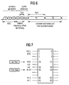
- Fig. 6 shows the structure of the known synchronization field.
- the synchronization field consists of so-called short symbols t1, t2, whilt6 and two long symbols T1, T2.
- the short symbols t1, t2....t6 are of interest.
- the short symbols t1, t2, ....t6 used for the amplifier gain control (t1, t2, t3) and the course frequency offset and timing control only the symbols t1, t2, t3 and t4 are actually generated, whereas the symbols t5, t6 are cyclic extensions (copies of the symbols t1 and t2, respectively). It is to be noted that fig.
- the symbols t1, t2, t3, t4 are generated by means of an OFDM modulation using selected subcarriers from the entire available subcarriers.
- the symbols used for the OFDM modulation as well as the mapping to the selected subcarriers will now be explained with reference to fig. 6.
- the multiplication by a factor of ⁇ 2 is in order to normalize the average power of the resulting OFDM symbol.
- the signal can be written as:
- T TSHORT1 is equal to nine 0.8 ⁇ sec periods, i.e. 7.2 ⁇ sec.
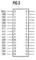
- the way to implement the inverse Fourier transform is by an IFFT (Inverse Fast Fourier Transform) algorithm. If, for example, a 64 point IFFT is used, the coefficients 1 to 24 are mapped to same numbered IFFT inputs, while the coefficients -24 to -1 are copied into IFFT inputs 40 to 63. The rest of the inputs, 25 to 39 and the 0 (DC) input, are set to zero. This mapping is illustrated in Fig. 7. After performing an IFFT the output is cyclically extended to the desired length.
- IFFT Inverse Fast Fourier Transform
- the resulting time domain signal consists of 4 periodically repeated short symbols t1, t2, t3, t4, and cyclically extended by a copy of t1, t2, which copy is depicted in fig.5 as t5, t6.
- IFFT inverse fast Fourier transform
- PAPR Peak-to-Average-Power-Ratio
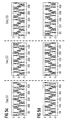
- Figures 8a, 8b show the "absolute" (sqrt ⁇ In*+Quad *Quad ⁇ ) value of the resulting time domain signal waveform with the sequences proposed by Lucent Technologies. Oversampling (8*) was considered in order to ensure the peak was captured correctly using the limited 64-point IFFT.
- Figures 8c, 8d show the real and imaginary part of the resulting transmitted time domain waveform.
- the resulting PAPR is 2.9991 dB (no oversampling) and 3.0093 dB (with 8 times oversampling).
- WO98/00946 discloses a timing and frequency synchronization of OFDM signals. This known method uses two OFDM training symbols to obtain full synchronization in less than two data frames.
- a first OFDM training symbol has only even-numbered subcarriers, and substantially no odd-numbered subcarriers, an arrangement that results in half-symbol symmetry.
- the second OFDM training symbol has even-numbered subcarriers differentially modulated relative to those of the first OFDM training symbol by a predetermined sequence.
- the synchronization is achieved by a computing matrix which utilized the unique properties of these two OFDM training symbols.
- a method for generating synchronization bursts for OFDM transmission systems having the features of claim 1 is provided. Symbols of a predefined symbol sequence are mapped according to a predefined mapping scheme on subcarriers of the OFDM system wherein the symbols of the predefined symbol sequence represent subcarriers with nonzero amplitudes.
- a synchronization burst is generated by inverse fast Fourier transforming the subcarriers mapped with a predefined symbol sequence.
- the predefined symbol sequence is optimized such that the envelope fluctuation of the time domain signal (Peak-to-average-power-ratio) is minimized.
- mapping of the symbols of the predefined symbol sequence and the Inverse Fast Fourier Transform can be set such that the resulting time domain signal of the synchronization burst represents a periodic nature.
- mapping of the symbols of the predefined symbol sequence and the Inverse Fast Fourier Transform is set such that one burst part of the synchronization burst in the time domain is generated and the periodic nature of the synchronization burst in the time domain is achieved by copying the one burst part.
- a method for synchronizing wireless OFDM systems wherein a synchronization burst is generated according to a method as set forth above and the synchronization burst is transmitted respectively before the transmission of data fields.
- time domain signals of the synchronization burst can be precomputed and stored in a memory, such that the computation of the time domain signal of the burst is only effected once.
- a OFDM transmitter having the features of claim 4 comprising a mapping unit for mapping the symbols of a predefined symbols sequence according to a predefined mapping scheme on subcarriers of the OFDM system, wherein the symbols of a predefined symbols sequence represent the subcarriers of the OFDM system with nonzero amplitudes.
- an inverse fast Fourier transforming unit is provided for generating a synchronization burst by inverse fast Fourier transforming the subcarriers of the OFDM mapped with said predefined symbols sequence.
- the mapping unit thereby is designed such that the resulting time domain signal of the synchronization burst represents a periodic nature.
- the mapping unit according to the present invention uses a predefined symbol sequence which is such that the envelope fluctuation of the time domain signal of the synchronization burst is minimized.
- a mobile communications device such as set forth above is used.
- the time domain synchronization burst structure as shown in Fig. 6 is maintained.
- the IFFT mapping as shown in Fig. 7 can be maintained or alternatively the IFFT mapping according to figure 3 can be used.
- the symbol sequences mapped to the subcarriers are optimized to sequences which result in a lower PAPR.
- the predefined symbol sequence therefore is chosen such that the envelope fluctuation of the time domain signal of the synchronization burst is minimized.
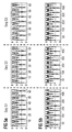
- Fig. 5a and 5b thereby show the time domain signal (magnitude) when using the optimized sequence according to the present invention in the case of no oversampling/8-times oversampling is effected.
- PAPR in decibel is limited to 2.059 (even when using a time domain oversampling to capture the actual peak).
- Fig. 5c and 5d show the in-phase and quadrature-phase component, respectively, of the resulting wave form. It is clearly visible that the full symbol consists of four repetitions of a short sequence.
- Fig. 5a to 5d show graphics corresponding to Fig. 4a to 4d for the other proposed sequences S1, S2 and S3.
- the PAPR is 3.01 dB and the dynamic range (defined as the ratio of the peak power to the minimum power) is 30.82 dB (see figures 9a and 9b).
- the PAPR is reduced to 2.06 dB, however, the dynamic range is increased as the signal power is '0' at some points.
- the sync symbol data 1 are prepared and mapped in a IFFT mapping unit 2 to the appropriate IFFT points.
- the subcarriers of the OFDM system are transformed by a IFFT unit 3 and then the time domain signal is extended in a time extension unit 4 by copying parts of the signals (for example, t1, t2 are copied to t5, t6).
- the time extended signal is then sent to the I/Q modulator 5.
- the time domain signal can be precomputed once in a computation unit 7 and then be stored in a memory 6 for the precomputed sample for the time signal. Then the time domain signal of the synchronization burst can be sent to the modulator 5 directly from the memory 6.
- the IFFT size is now only 16 (instead of 64 as it is the case in figure 7). Only one of the bursts t1, t2, ....t6 will be generated. The other bursts can be generated by copying to retain the periodic nature of the synchronization time domain signal necessary for the correlation and synchronization on the receiving side. Therefore for example the time extension unit 4 can perform the copying of the 16-sample burst t1 generated by the IFFT 16 according to figure 7 to the other burst t2, t3, ...t6. Obviously the mapping scheme according to figure 3 reduces the computing effort necessary for the IFFT. The periodic nature of the time domain signal of the SYNCH bursts is therefore no longer achieved by the IFFT step, but by copying the burst t1 generated with the simplified IFFT mapping scheme.
- mapping scheme shown in figure 3 is also advantageous in combination with the precomputing technique shown in figure 2.
- a synchronization burst structure to be used in high speed wireless transmission systems is proposed.
- the synchronization burst is constructed using especially designed OFDM symbols and time domain repetitions.
- the resulting synchronization burst achieves a high timing detection and frequency offset estimation accuracy.
- the burst is optimized to achieve a very low envelope fluctuation (Low peak-to-average-power-ratio) to reduce the complexity on the receiver and to reduce time and frequency acquisition time at the receiver.
- the synchronization performance can further be improved.
- the envelope of the OFDM based synchronization burst in the time domain is reduced, the AGC pool-in speed at the receiver can be improved and an accurate time and frequency synchronization can be achieved.
- the synchronization complexity on the receiver side can be reduced due to the reduced resolution requirements necessary due to reduced envelope fluctuation.
Description
S -24 , 24 = √2*{1+j, 0,0,0,1+j,0,0,0,-1-j,0,0,0,-1-j,0,0,0,1-j,0,0,0,-1-j,0,0,0,0,
0,0,0,1+j,0,0,0,1+j,0,0,0,-1-j,0,0,0,1+j,0,0,0,-1+j,0,0,0,1+j}

n=2m,
Ci-1=±C1-i,
n being the number of symbols of the predefined symbol sequence,
m being an integer larger than one,
C being the symbol value, and
i being an integer running from 1 to m.
n = 2m,
Ci-1=±Cn-i
wherein n is a number of symbols of the predefined symbol sequence,
m is an integer larger than 1,
c is the symbol value, and
i is an integer value running from 1 to m.
| Complex symbol mapping | ||
| Symbol | ||
| A | exp(j π / 4) | |
| -A | -exp(j π / 4)=exp(j 5π / 4) | |
| B | exp(j π / 4+j π / 2)=exp(j 3π / 4) | |
| -B | -exp(j 3π / 4)=exp(j 7π / 4) | |
S=2* { C00, 0, 0, 0, C01, 0, 0, 0, C02, 0, 0, 0, C03, 0, 0, 0, C04, 0, 0, 0,
C05, 0, 0, 0, 0, 0, 0, 0, C06, 0, 0, 0, C07, 0, 0, 0, C08, 0, 0, 0, C09, 0, 0, 0,
C10, 0, 0, 0, C11 }
| C00 | C01 | C02 | C03 | C04 | C05 | C06 | C07 | C08 | C09 | C10 | C11 | |
| Seq 1 | A | -A | A | -A | -A | A | -A | -A | A | A | A | A |
- An OFDM based SYNCH symbol with a reduced Peak-to-Average-Power-Ratio (PARP) is proposed,
- Improved synchronization performance (compared to the state of the art proposal),
- Reduced AGC (automatic gain control) pull-in time due to reduced dynamic range of the SYNCH burst,
- Improved AGC settlement (AGC has to adjust to a incoming signal level that later on now overflow/underflow in the AD happens. The reduced dynamic range of the SYNCH burst help to find this reference level more accurate),
- Reduced synchronization detection complexity on the receiver (reduced resolution necessary due to reduced envelope fluctuation).
Claims (8)
- A method for generating synchronization bursts for OFDM transmission systems, comprising the following steps:characterized in thatmapping (2) the symbols of a predefined symbol sequence according to a predefined mapping scheme on subcarriers S of the OFDM system, wherein the symbols of the predefined symbol sequence represent subcarriers of the OFDM system with non-zero-amplitude, andgenerating a synchronization burst by Inverse Fast Fourier Transforming (3) the subcarriers S of the OFDM system mapped with the symbols of said predefined symbol sequence,
the predefined symbol sequence is set such that the envelope fluctuation of the time domain signal of the synchronization burst is minimized and the symbols of the predefined symbols sequence are expressed as
A -A A -A -A A -A -A A A A A
A being a complex value. - A method for synchronizing wireless OFDM systems,
characterized by the steps ofgenerating a synchronization burst according to a method according to claim 1, andtransmitting the synchronization burst. - A method according to claim 2,
characterized in that
the time domain signal of the synchronization burst is precomputed (7) and stored in a memory (6). - An OFDM transmitter, comprising:characterized in thata unit (2) for mapping the symbols of a predefined symbol sequence according to a predefined mapping scheme on subcarriers of the OFDM system, wherein the symbols of the predefined symbol sequence represent subcarriers of the OFDM system with non-zero-amplitude, anda unit (3) for generating a synchronization burst by Inverse Fast Fourier Transforming (3) the subcarriers of the OFDM system mapped with the symbols of said predefined symbol sequence,
the mapping unit (2) is designed to modulate the subcarriers such that the envelope fluctuation of the time domain signal of the synchronization burst is minimized by using the following predefined symbol sequence:
A -A A -A -A A -A -A A A A A
A being a complex value. - An OFDM transmitter according to claim 4,
characterized by
a time extension unit (4) adapted to copy parts of the synchronisation burst to achieve a periodic nature of the time domain signal. - An OFDM transmitter according to anyone of claims 4 or 5,
characterized by
a processing unit (7) for precomputing the time domain signal of the synchronization burst and a memory (6) for storing the precomputed time domain signal of the synchronization burst. - A mobile communications device,
comprising a transmitter according to anyone of claims 4 to 6. - A synchronization burst signal for synchronizing OFDM systems generated by a method according to anyone of claims 1 to 3.
Priority Applications (20)
| Application Number | Priority Date | Filing Date | Title |
|---|---|---|---|
| AT09160351T ATE496471T1 (en) | 1999-02-22 | 1999-02-22 | SYNCHRONIZATION ATTACHMENT STRUCTURE FOR OFDM SYSTEM |
| DE69943152T DE69943152D1 (en) | 1999-01-08 | 1999-02-22 | Synchronization header structure for OFDM system |
| EP04002920A EP1439677B9 (en) | 1999-01-08 | 1999-02-22 | Synchronisation symbol structure for an OFDM system |
| EP09160351A EP2088728B1 (en) | 1999-02-22 | 1999-02-22 | Synchronization preamble structure for OFDM system |
| EP06014693A EP1722527B1 (en) | 1999-01-08 | 1999-02-22 | Synchronisation symbol structure for OFDM system |
| EP06014694A EP1705852B1 (en) | 1999-01-08 | 1999-02-22 | Synchronisation symbol structure for OFDM system |
| EP09160346A EP2088727B1 (en) | 1999-02-22 | 1999-02-22 | Synchronisation symbol structure for OFDM system |
| EP99103379A EP1018827B1 (en) | 1999-01-08 | 1999-02-22 | Synchronisation structure for OFDM system |
| EP05002279A EP1530336B1 (en) | 1999-01-08 | 1999-02-22 | Synchronization preamble structure for OFDM system |
| CA002291847A CA2291847C (en) | 1999-01-08 | 1999-12-06 | Synchronization symbol structure using ofdm based transmission method |
| KR1020000000479A KR100712865B1 (en) | 1999-01-08 | 2000-01-06 | Synchronization symbol structure using OFDM based transmission method |
| US09/479,281 US6654339B1 (en) | 1999-01-08 | 2000-01-06 | Synchronization symbol structure using OFDM based transmission method |
| JP2000006000A JP4050437B2 (en) | 1999-01-08 | 2000-01-07 | Synchronous burst generation method, radio orthogonal frequency division multiplexing synchronization method, orthogonal frequency division multiplexing transmission apparatus and mobile communication apparatus |
| US11/286,440 USRE40568E1 (en) | 1999-01-08 | 2005-11-23 | Synchronization symbol structure using OFDM based transmission method |
| US12/258,939 USRE41486E1 (en) | 1999-01-08 | 2008-10-27 | Synchronization symbol structure using OFDM based transmission method |
| US12/259,018 USRE41431E1 (en) | 1999-01-08 | 2008-10-27 | Synchronization symbol structure using OFDM based transmission method |
| US12/258,799 USRE41470E1 (en) | 1999-01-08 | 2008-10-27 | Synchronization symbol structure using OFDM based transmission method |
| US12/258,984 USRE41641E1 (en) | 1999-01-08 | 2008-10-27 | Synchronization symbol structure using OFDM based transmission method |
| US12/259,045 USRE41606E1 (en) | 1999-01-08 | 2008-10-27 | Synchronization symbol structure using OFDM based transmission method |
| US12/259,063 USRE41432E1 (en) | 1999-01-08 | 2008-10-27 | Synchronization symbol structure using OFDM based transmission method |
Applications Claiming Priority (3)
| Application Number | Priority Date | Filing Date | Title |
|---|---|---|---|
| EP99100263 | 1999-01-08 | ||
| EP99100263 | 1999-01-08 | ||
| EP99103379A EP1018827B1 (en) | 1999-01-08 | 1999-02-22 | Synchronisation structure for OFDM system |
Related Child Applications (3)
| Application Number | Title | Priority Date | Filing Date |
|---|---|---|---|
| EP06014694A Division EP1705852B1 (en) | 1999-01-08 | 1999-02-22 | Synchronisation symbol structure for OFDM system |
| EP04002920A Division EP1439677B9 (en) | 1999-01-08 | 1999-02-22 | Synchronisation symbol structure for an OFDM system |
| EP04002920.9 Division-Into | 2004-02-10 |
Publications (2)
| Publication Number | Publication Date |
|---|---|
| EP1018827A1 EP1018827A1 (en) | 2000-07-12 |
| EP1018827B1 true EP1018827B1 (en) | 2004-05-06 |
Family
ID=26152852
Family Applications (5)
| Application Number | Title | Priority Date | Filing Date |
|---|---|---|---|
| EP06014694A Expired - Lifetime EP1705852B1 (en) | 1999-01-08 | 1999-02-22 | Synchronisation symbol structure for OFDM system |
| EP04002920A Expired - Lifetime EP1439677B9 (en) | 1999-01-08 | 1999-02-22 | Synchronisation symbol structure for an OFDM system |
| EP99103379A Expired - Lifetime EP1018827B1 (en) | 1999-01-08 | 1999-02-22 | Synchronisation structure for OFDM system |
| EP06014693A Expired - Lifetime EP1722527B1 (en) | 1999-01-08 | 1999-02-22 | Synchronisation symbol structure for OFDM system |
| EP05002279A Expired - Lifetime EP1530336B1 (en) | 1999-01-08 | 1999-02-22 | Synchronization preamble structure for OFDM system |
Family Applications Before (2)
| Application Number | Title | Priority Date | Filing Date |
|---|---|---|---|
| EP06014694A Expired - Lifetime EP1705852B1 (en) | 1999-01-08 | 1999-02-22 | Synchronisation symbol structure for OFDM system |
| EP04002920A Expired - Lifetime EP1439677B9 (en) | 1999-01-08 | 1999-02-22 | Synchronisation symbol structure for an OFDM system |
Family Applications After (2)
| Application Number | Title | Priority Date | Filing Date |
|---|---|---|---|
| EP06014693A Expired - Lifetime EP1722527B1 (en) | 1999-01-08 | 1999-02-22 | Synchronisation symbol structure for OFDM system |
| EP05002279A Expired - Lifetime EP1530336B1 (en) | 1999-01-08 | 1999-02-22 | Synchronization preamble structure for OFDM system |
Country Status (5)
| Country | Link |
|---|---|
| US (8) | US6654339B1 (en) |
| EP (5) | EP1705852B1 (en) |
| JP (1) | JP4050437B2 (en) |
| KR (1) | KR100712865B1 (en) |
| CA (1) | CA2291847C (en) |
Families Citing this family (64)
| Publication number | Priority date | Publication date | Assignee | Title |
|---|---|---|---|---|
| EP1705852B1 (en) | 1999-01-08 | 2010-02-10 | Sony Deutschland Gmbh | Synchronisation symbol structure for OFDM system |
| DE69922794T2 (en) | 1999-06-16 | 2005-05-19 | Sony International (Europe) Gmbh | Optimized synchronization preamble structure for OFDM system |
| EP2262157A3 (en) | 2000-07-05 | 2011-03-23 | Sony Deutschland Gmbh | Pilot pattern design for a STTD scheme in an OFDM system |
| US7295509B2 (en) | 2000-09-13 | 2007-11-13 | Qualcomm, Incorporated | Signaling method in an OFDM multiple access system |
| US9130810B2 (en) | 2000-09-13 | 2015-09-08 | Qualcomm Incorporated | OFDM communications methods and apparatus |
| US6754170B1 (en) * | 2000-09-29 | 2004-06-22 | Symbol Technologies, Inc. | Timing synchronization in OFDM communications receivers |
| US6950475B1 (en) * | 2000-12-11 | 2005-09-27 | Cisco Technology, Inc. | OFDM receiver clock synchronization system |
| CA2477883C (en) * | 2002-03-07 | 2013-05-21 | Naftali Chayat | Hierarchical preamble constructions for ofdma based on complementary sequences |
| KR20040029253A (en) * | 2002-09-30 | 2004-04-06 | 삼성전자주식회사 | Apparatus for generating preamble sequence in communication system using orthogonal frequency division multiplexing scheme and method thereof |
| WO2004039026A1 (en) * | 2002-10-23 | 2004-05-06 | Samsung Electronics Co., Ltd. | Apparatus and method for generating a preamble sequence in an ofdm communication system |
| CA2474233A1 (en) * | 2002-11-30 | 2004-06-17 | Samsung Electronics Co., Ltd. | Apparatus and method for generating a preamble sequence in an ofdm communication system |
| KR100905572B1 (en) * | 2002-12-03 | 2009-07-02 | 삼성전자주식회사 | Apparatus and method for generating preamble sequence in a communication system using orthogonal frequency division multiplexing scheme |
| CA2559814C (en) | 2004-04-28 | 2012-05-29 | Samsung Electronics Co., Ltd. | Method and apparatus for generating preamble sequence for adaptive antenna system in orthogonal frequency division multiple access communication system |
| US9137822B2 (en) | 2004-07-21 | 2015-09-15 | Qualcomm Incorporated | Efficient signaling over access channel |
| US9148256B2 (en) | 2004-07-21 | 2015-09-29 | Qualcomm Incorporated | Performance based rank prediction for MIMO design |
| US7961828B2 (en) * | 2004-10-06 | 2011-06-14 | Motorola Mobility, Inc. | Sync bursts frequency offset compensation |
| CN1780276B (en) * | 2004-11-25 | 2012-01-04 | 都科摩(北京)通信技术研究中心有限公司 | Combined time synchronizing and frequency bias evaluation and evaluating device for orthogonal frequency division duplex system |
| US9246560B2 (en) | 2005-03-10 | 2016-01-26 | Qualcomm Incorporated | Systems and methods for beamforming and rate control in a multi-input multi-output communication systems |
| US9154211B2 (en) | 2005-03-11 | 2015-10-06 | Qualcomm Incorporated | Systems and methods for beamforming feedback in multi antenna communication systems |
| US8446892B2 (en) | 2005-03-16 | 2013-05-21 | Qualcomm Incorporated | Channel structures for a quasi-orthogonal multiple-access communication system |
| US9143305B2 (en) | 2005-03-17 | 2015-09-22 | Qualcomm Incorporated | Pilot signal transmission for an orthogonal frequency division wireless communication system |
| US9461859B2 (en) | 2005-03-17 | 2016-10-04 | Qualcomm Incorporated | Pilot signal transmission for an orthogonal frequency division wireless communication system |
| US9520972B2 (en) | 2005-03-17 | 2016-12-13 | Qualcomm Incorporated | Pilot signal transmission for an orthogonal frequency division wireless communication system |
| JP4429945B2 (en) | 2005-03-23 | 2010-03-10 | 株式会社エヌ・ティ・ティ・ドコモ | MIMO multiplex communication apparatus and signal separation method |
| US9184870B2 (en) | 2005-04-01 | 2015-11-10 | Qualcomm Incorporated | Systems and methods for control channel signaling |
| US9408220B2 (en) | 2005-04-19 | 2016-08-02 | Qualcomm Incorporated | Channel quality reporting for adaptive sectorization |
| US9036538B2 (en) | 2005-04-19 | 2015-05-19 | Qualcomm Incorporated | Frequency hopping design for single carrier FDMA systems |
| US8611284B2 (en) | 2005-05-31 | 2013-12-17 | Qualcomm Incorporated | Use of supplemental assignments to decrement resources |
| US8565194B2 (en) | 2005-10-27 | 2013-10-22 | Qualcomm Incorporated | Puncturing signaling channel for a wireless communication system |
| US8879511B2 (en) | 2005-10-27 | 2014-11-04 | Qualcomm Incorporated | Assignment acknowledgement for a wireless communication system |
| US8462859B2 (en) | 2005-06-01 | 2013-06-11 | Qualcomm Incorporated | Sphere decoding apparatus |
| US9179319B2 (en) | 2005-06-16 | 2015-11-03 | Qualcomm Incorporated | Adaptive sectorization in cellular systems |
| US8599945B2 (en) | 2005-06-16 | 2013-12-03 | Qualcomm Incorporated | Robust rank prediction for a MIMO system |
| US7804764B2 (en) * | 2005-08-03 | 2010-09-28 | National University Corporation NARA Institute of Science and Technology | Transmitter and receiver |
| US8885628B2 (en) | 2005-08-08 | 2014-11-11 | Qualcomm Incorporated | Code division multiplexing in a single-carrier frequency division multiple access system |
| US9209956B2 (en) | 2005-08-22 | 2015-12-08 | Qualcomm Incorporated | Segment sensitive scheduling |
| US20070041457A1 (en) | 2005-08-22 | 2007-02-22 | Tamer Kadous | Method and apparatus for providing antenna diversity in a wireless communication system |
| US8644292B2 (en) | 2005-08-24 | 2014-02-04 | Qualcomm Incorporated | Varied transmission time intervals for wireless communication system |
| US9136974B2 (en) | 2005-08-30 | 2015-09-15 | Qualcomm Incorporated | Precoding and SDMA support |
| US9210651B2 (en) | 2005-10-27 | 2015-12-08 | Qualcomm Incorporated | Method and apparatus for bootstraping information in a communication system |
| US8582509B2 (en) | 2005-10-27 | 2013-11-12 | Qualcomm Incorporated | Scalable frequency band operation in wireless communication systems |
| US9225488B2 (en) | 2005-10-27 | 2015-12-29 | Qualcomm Incorporated | Shared signaling channel |
| US8477684B2 (en) | 2005-10-27 | 2013-07-02 | Qualcomm Incorporated | Acknowledgement of control messages in a wireless communication system |
| US8693405B2 (en) | 2005-10-27 | 2014-04-08 | Qualcomm Incorporated | SDMA resource management |
| US8045512B2 (en) | 2005-10-27 | 2011-10-25 | Qualcomm Incorporated | Scalable frequency band operation in wireless communication systems |
| US9088384B2 (en) | 2005-10-27 | 2015-07-21 | Qualcomm Incorporated | Pilot symbol transmission in wireless communication systems |
| US9144060B2 (en) | 2005-10-27 | 2015-09-22 | Qualcomm Incorporated | Resource allocation for shared signaling channels |
| US9172453B2 (en) | 2005-10-27 | 2015-10-27 | Qualcomm Incorporated | Method and apparatus for pre-coding frequency division duplexing system |
| US9225416B2 (en) | 2005-10-27 | 2015-12-29 | Qualcomm Incorporated | Varied signaling channels for a reverse link in a wireless communication system |
| US8582548B2 (en) | 2005-11-18 | 2013-11-12 | Qualcomm Incorporated | Frequency division multiple access schemes for wireless communication |
| US8831607B2 (en) | 2006-01-05 | 2014-09-09 | Qualcomm Incorporated | Reverse link other sector communication |
| CN1852281B (en) * | 2006-01-23 | 2010-06-09 | 北京邮电大学 | Synchronizing method for quadrature frequency division multiple access system |
| US7983143B2 (en) | 2006-02-08 | 2011-07-19 | Motorola Mobility, Inc. | Method and apparatus for initial acquisition and cell search for an OFDMA system |
| US7911935B2 (en) | 2006-02-08 | 2011-03-22 | Motorola Mobility, Inc. | Method and apparatus for interleaving sequence elements of an OFDMA synchronization channel |
| US7961591B2 (en) | 2006-03-20 | 2011-06-14 | Fujitsu Limited | OFDM communication systems, transmitters and methods |
| DE602006005606D1 (en) * | 2006-03-20 | 2009-04-23 | Fujitsu Ltd | Symbol for subcarrier assignment in OFDM communication systems and procedures |
| CN101022438B (en) * | 2006-03-30 | 2011-12-14 | 北京新岸线移动通信技术有限公司 | Compatible DAB digital broadcasting receiver carrier synchronizing method and system |
| DE202008018579U1 (en) | 2007-05-02 | 2016-01-14 | Huawei Technologies Co., Ltd. | Device for producing a synchronization signal in a communication system |
| CN101083508B (en) * | 2007-07-19 | 2010-06-02 | 清华大学 | OFDM modulation system performance test method based on low peak-valley ratio sequence transmission |
| CN101420411B (en) * | 2008-12-05 | 2011-02-09 | 航天恒星科技有限公司 | Fast carrier capture method with low signal-noise ratio |
| CN106685876B (en) * | 2016-11-14 | 2021-08-10 | 西南石油大学 | Multi-dimensional PTS method for reducing peak-to-average power ratio of OFDM system |
| EP3481020B1 (en) * | 2017-11-07 | 2021-09-01 | Siemens Aktiengesellschaft | Method for synchronising transmission and reception units in multi-carrier signal transmission |
| CN110535795B (en) * | 2018-05-24 | 2021-11-05 | 中兴通讯股份有限公司 | Signal processing method and device |
| CN113315730B (en) * | 2021-05-24 | 2022-12-27 | 扬州大学 | Time-frequency synchronization method based on filter multi-carrier system |
Family Cites Families (58)
| Publication number | Priority date | Publication date | Assignee | Title |
|---|---|---|---|---|
| US5450456A (en) * | 1993-11-12 | 1995-09-12 | Daimler Benz Ag | Method and arrangement for measuring the carrier frequency deviation in a multi-channel transmission system |
| US5732113A (en) * | 1996-06-20 | 1998-03-24 | Stanford University | Timing and frequency synchronization of OFDM signals |
| DE69719278T2 (en) * | 1996-10-14 | 2003-11-13 | Nippon Telegraph & Telephone | Method and apparatus for reducing the ratio of peak to average power |
| GB9625094D0 (en) * | 1996-12-03 | 1997-01-22 | Ensigma Ltd | Apparatus and methods for measuring coarse frequency offset of a multi-carrier signal |
| US5990176A (en) | 1997-01-27 | 1999-11-23 | Abbott Laboratories | Fluoroether compositions and methods for inhibiting their degradation in the presence of a Lewis acid |
| US6005840A (en) * | 1997-04-01 | 1999-12-21 | Lucent Technologies Inc. | Complementary encoding and modulation system for use in an orthogonal frequency division multiplexing transmitter system and method thereof |
| DE19733825A1 (en) * | 1997-08-05 | 1999-02-11 | Siemens Ag | Method and arrangement for combined measurement of the start of a data block and the carrier frequency offset in a multicarrier transmission system for irregular transmission of data blocks |
| EP0899923A1 (en) | 1997-08-29 | 1999-03-03 | Sony International (Europe) GmbH | Transmission of power control signals in a multicarrier modulation system |
| DE69739776D1 (en) | 1997-09-04 | 2010-04-01 | Sony Deutschland Gmbh | Method for receiving and receiving OFDM signals |
| EP2782307B1 (en) | 1997-11-05 | 2016-03-30 | Sony Deutschland Gmbh | Synchronisation of digital communication systems |
| EP0915586B1 (en) | 1997-11-07 | 2005-05-18 | Sony International (Europe) GmbH | Multicarrier transmission, compatible with the existing GSM system |
| WO1999033166A1 (en) | 1997-12-18 | 1999-07-01 | Sony International (Europe) Gmbh | N-port direct receiver |
| KR100543259B1 (en) | 1998-02-13 | 2006-01-20 | 소니 가부시끼 가이샤 | Transmitting method, receiving method, transmitter, and receiver |
| EP0938193A1 (en) | 1998-02-18 | 1999-08-25 | Sony International (Europe) GmbH | Header structure for TDD systems |
| EP0939527B1 (en) | 1998-02-18 | 2007-12-05 | Sony Deutschland GmbH | Mapping of multicarrier signals into GSM time slots |
| EP0938208A1 (en) | 1998-02-22 | 1999-08-25 | Sony International (Europe) GmbH | Multicarrier transmission, compatible with the existing GSM system |
| US6470055B1 (en) * | 1998-08-10 | 2002-10-22 | Kamilo Feher | Spectrally efficient FQPSK, FGMSK, and FQAM for enhanced performance CDMA, TDMA, GSM, OFDN, and other systems |
| DE69831149T2 (en) | 1998-08-28 | 2006-05-24 | Sony International (Europe) Gmbh | Apparatus and method for universal PSK modulation |
| EP0984595B1 (en) | 1998-09-03 | 2007-04-25 | Sony Deutschland GmbH | Blind modulation detection |
| EP0984596A1 (en) | 1998-09-03 | 2000-03-08 | Sony International (Europe) GmbH | Adpative PSK system and timing offset compensation circuit |
| DE69829661T2 (en) | 1998-09-17 | 2006-03-09 | Sony International (Europe) Gmbh | Soft decision method and apparatus in 8-PSK demodulation |
| US6452987B1 (en) * | 1998-11-25 | 2002-09-17 | Lucent Technologies Inc. | Fast start-up in discrete multi-tone (DMT) based communications system |
| DE69842089D1 (en) | 1998-11-30 | 2011-02-17 | Sony Deutschland Gmbh | Dual Band end receivers |
| EP1009098A1 (en) | 1998-12-10 | 2000-06-14 | Sony International (Europe) GmbH | Error correction using a turbo code and a CRC |
| DE69829757T2 (en) | 1998-12-18 | 2006-01-12 | Sony International (Europe) Gmbh | Three-gate circuit receiver |
| EP1705852B1 (en) | 1999-01-08 | 2010-02-10 | Sony Deutschland Gmbh | Synchronisation symbol structure for OFDM system |
| US8861622B2 (en) | 1999-02-24 | 2014-10-14 | Sony Deutschland Gmbh | Transmitting apparatus and method for a digital telecommunication system |
| EP1717984B1 (en) | 1999-02-24 | 2010-05-19 | Sony Deutschland Gmbh | Receiving apparatus and synchronising method for a digital telecommunication system |
| EP1039661A1 (en) | 1999-03-03 | 2000-09-27 | Sony International (Europe) GmbH | Multicast channel for a CDMA system |
| EP1037481A1 (en) | 1999-03-15 | 2000-09-20 | Sony International (Europe) GmbH | Simultaneous transmission of random access bursts |
| DE69909589T2 (en) | 1999-04-12 | 2004-06-03 | Sony International (Europe) Gmbh | Communication device and method for distinguishing between different data brushes in a digital telecommunications system |
| EP1505787B1 (en) | 1999-04-23 | 2006-10-18 | Sony Deutschland GmbH | Synchronization preamble in an OFDM system |
| EP1056193B1 (en) | 1999-05-27 | 2005-04-27 | Sony International (Europe) GmbH | Down converter and demodulator using a three port junction |
| DE69922794T2 (en) | 1999-06-16 | 2005-05-19 | Sony International (Europe) Gmbh | Optimized synchronization preamble structure for OFDM system |
| EP1061660B1 (en) | 1999-06-16 | 2006-08-09 | Sony Deutschland GmbH | N-port receiver with RF/LO isolation |
| EP1065855A1 (en) | 1999-06-29 | 2001-01-03 | Sony International (Europe) GmbH | Adaptation of cyclic extensions in an OFDM communication system |
| EP1067675B1 (en) | 1999-07-08 | 2005-04-27 | Sony International (Europe) GmbH | Calibration of a N-port receiver |
| EP1067705B1 (en) | 1999-07-09 | 2009-08-26 | Sony Deutschland GmbH | Cell coverage extension in downlink power controlled radio communication systems |
| DE69926064T2 (en) | 1999-09-29 | 2006-04-13 | Sony International (Europe) Gmbh | Three-port structure with modulated injection signal |
| KR20000000479A (en) * | 1999-10-27 | 2000-01-15 | 신창우 | Skin for wig |
| EP1120899B1 (en) | 2000-01-24 | 2003-09-17 | Sony International (Europe) GmbH | Demodulation structure and method |
| US7106821B2 (en) | 2000-03-15 | 2006-09-12 | Sony Corporation | Data modulation method, data modulation device and communication device |
| EP1162764B1 (en) | 2000-06-05 | 2007-08-15 | Sony Deutschland GmbH | Indoor wireless system using active reflector |
| EP1170916B1 (en) | 2000-07-05 | 2006-12-27 | Sony Deutschland GmbH | Channel estimator for OFDM system |
| EP1170917B1 (en) | 2000-07-06 | 2006-10-04 | Sony Deutschland GmbH | Method and device to provide an OFDM up-link using Time-Frequency interleaving |
| EP1178641B1 (en) | 2000-08-01 | 2007-07-25 | Sony Deutschland GmbH | Frequency reuse scheme for OFDM systems |
| DE60028200T2 (en) | 2000-08-01 | 2007-03-15 | Sony Deutschland Gmbh | Device and method for channel estimation for OFDM system |
| EP2259480A3 (en) | 2000-11-20 | 2012-05-02 | Sony Deutschland Gmbh | Adaptive subcarrier loading |
| DE60005374T2 (en) | 2000-11-20 | 2004-04-22 | Sony International (Europe) Gmbh | OFDM system with transmitter antenna diversity and pre-equalization |
| US6407846B1 (en) * | 2001-03-16 | 2002-06-18 | All Optical Networks, Inc. | Photonic wavelength shifting method |
| ES2278661T3 (en) | 2001-07-10 | 2007-08-16 | Sony Deutschland Gmbh | REFERENCE SYMBOLS FOR THE ESTIMATION OF CHANNELS WITH MULTIPORT CARRIAGE. |
| EP1276251B1 (en) | 2001-07-11 | 2011-05-11 | Sony Deutschland GmbH | Method for calculating a weighting vector for an antenna array |
| US7037527B2 (en) | 2002-01-25 | 2006-05-02 | University Of Rhode Island | Bifunctionalized polyester material for surface treatment and biomodification |
| EP1379026A1 (en) | 2002-07-03 | 2004-01-07 | Sony International (Europe) GmbH | Dual rate wireless transmission system |
| EP1545069A1 (en) | 2003-12-19 | 2005-06-22 | Sony International (Europe) GmbH | Remote polling and control system |
| DE602004005316T2 (en) | 2004-05-11 | 2008-03-06 | Sony Deutschland Gmbh | Pole down converter with a symmetric resonator |
| EP1630713B1 (en) | 2004-08-24 | 2020-05-20 | Sony Deutschland GmbH | Backscatter interrogator reception method and interrogator for a modulated backscatter system |
| EP1657852A1 (en) | 2004-11-15 | 2006-05-17 | Sony Deutschland GmbH | Beaconless communication in ad hoc networks |
-
1999
- 1999-02-22 EP EP06014694A patent/EP1705852B1/en not_active Expired - Lifetime
- 1999-02-22 EP EP04002920A patent/EP1439677B9/en not_active Expired - Lifetime
- 1999-02-22 EP EP99103379A patent/EP1018827B1/en not_active Expired - Lifetime
- 1999-02-22 EP EP06014693A patent/EP1722527B1/en not_active Expired - Lifetime
- 1999-02-22 EP EP05002279A patent/EP1530336B1/en not_active Expired - Lifetime
- 1999-12-06 CA CA002291847A patent/CA2291847C/en not_active Expired - Lifetime
-
2000
- 2000-01-06 US US09/479,281 patent/US6654339B1/en not_active Ceased
- 2000-01-06 KR KR1020000000479A patent/KR100712865B1/en active IP Right Grant
- 2000-01-07 JP JP2000006000A patent/JP4050437B2/en not_active Expired - Lifetime
-
2005
- 2005-11-23 US US11/286,440 patent/USRE40568E1/en not_active Expired - Lifetime
-
2008
- 2008-10-27 US US12/259,063 patent/USRE41432E1/en not_active Expired - Lifetime
- 2008-10-27 US US12/258,984 patent/USRE41641E1/en not_active Expired - Lifetime
- 2008-10-27 US US12/258,939 patent/USRE41486E1/en not_active Expired - Lifetime
- 2008-10-27 US US12/259,045 patent/USRE41606E1/en not_active Expired - Lifetime
- 2008-10-27 US US12/259,018 patent/USRE41431E1/en not_active Expired - Lifetime
- 2008-10-27 US US12/258,799 patent/USRE41470E1/en not_active Expired - Lifetime
Also Published As
| Publication number | Publication date |
|---|---|
| EP1439677B9 (en) | 2007-11-07 |
| EP1439677A1 (en) | 2004-07-21 |
| EP1018827A1 (en) | 2000-07-12 |
| EP1722527B1 (en) | 2008-08-06 |
| EP1705852A3 (en) | 2006-11-15 |
| EP1705852A2 (en) | 2006-09-27 |
| USRE40568E1 (en) | 2008-11-11 |
| EP1530336A1 (en) | 2005-05-11 |
| USRE41432E1 (en) | 2010-07-13 |
| USRE41470E1 (en) | 2010-08-03 |
| JP4050437B2 (en) | 2008-02-20 |
| JP2000209183A (en) | 2000-07-28 |
| EP1722527A1 (en) | 2006-11-15 |
| USRE41486E1 (en) | 2010-08-10 |
| USRE41431E1 (en) | 2010-07-13 |
| CA2291847A1 (en) | 2000-07-08 |
| CA2291847C (en) | 2005-09-13 |
| EP1439677B1 (en) | 2007-06-13 |
| EP1705852B1 (en) | 2010-02-10 |
| US6654339B1 (en) | 2003-11-25 |
| KR20000053406A (en) | 2000-08-25 |
| USRE41641E1 (en) | 2010-09-07 |
| KR100712865B1 (en) | 2007-05-03 |
| EP1530336B1 (en) | 2009-06-10 |
| USRE41606E1 (en) | 2010-08-31 |
Similar Documents
| Publication | Publication Date | Title |
|---|---|---|
| EP1018827B1 (en) | Synchronisation structure for OFDM system | |
| EP1061705B1 (en) | Optimized synchronization preamble structure for OFDM system | |
| EP0839423B1 (en) | Pulse shaping for multicarrier modulation | |
| EP1505787B1 (en) | Synchronization preamble in an OFDM system | |
| EP2315386B1 (en) | OFDM communications methods and apparatus | |
| KR100263372B1 (en) | Coarse frequency acquistion method and thereof appratus for orthogonal frequency division multiplexing systems | |
| US8223858B2 (en) | Time synchronization method and frequency offset estimation method using the same in OFDM network | |
| KR100841064B1 (en) | Distributed pilot multicarrier signal designed to limit interference affecting said pilots | |
| EP0849919A2 (en) | Shaping functions for multicarrier modulation systems | |
| EP2088727B1 (en) | Synchronisation symbol structure for OFDM system | |
| EP2088728B1 (en) | Synchronization preamble structure for OFDM system | |
| KR100770558B1 (en) | Optimized synchronization preamble structure | |
| Eyadeh | Performance of Frame Synchronization Symbols for an OFDM System in Dispersive Channels |
Legal Events
| Date | Code | Title | Description |
|---|---|---|---|
| PUAI | Public reference made under article 153(3) epc to a published international application that has entered the european phase |
Free format text: ORIGINAL CODE: 0009012 |
|
| AK | Designated contracting states |
Kind code of ref document: A1 Designated state(s): AT DE FI FR GB SE |
|
| AX | Request for extension of the european patent |
Free format text: AL;LT;LV;MK;RO;SI |
|
| 17P | Request for examination filed |
Effective date: 20010111 |
|
| AKX | Designation fees paid |
Free format text: AT DE FI FR GB SE |
|
| 17Q | First examination report despatched |
Effective date: 20020926 |
|
| GRAP | Despatch of communication of intention to grant a patent |
Free format text: ORIGINAL CODE: EPIDOSNIGR1 |
|
| RAP1 | Party data changed (applicant data changed or rights of an application transferred) |
Owner name: SONY INTERNATIONAL (EUROPE) GMBH |
|
| GRAS | Grant fee paid |
Free format text: ORIGINAL CODE: EPIDOSNIGR3 |
|
| GRAA | (expected) grant |
Free format text: ORIGINAL CODE: 0009210 |
|
| AK | Designated contracting states |
Kind code of ref document: B1 Designated state(s): AT DE FI FR GB SE |
|
| REG | Reference to a national code |
Ref country code: SE Ref legal event code: TRGR |
|
| REG | Reference to a national code |
Ref country code: GB Ref legal event code: FG4D |
|
| REF | Corresponds to: |
Ref document number: 69916989 Country of ref document: DE Date of ref document: 20040609 Kind code of ref document: P |
|
| ET | Fr: translation filed | ||
| PLBE | No opposition filed within time limit |
Free format text: ORIGINAL CODE: 0009261 |
|
| STAA | Information on the status of an ep patent application or granted ep patent |
Free format text: STATUS: NO OPPOSITION FILED WITHIN TIME LIMIT |
|
| 26N | No opposition filed |
Effective date: 20050208 |
|
| REG | Reference to a national code |
Ref country code: GB Ref legal event code: 732E |
|
| REG | Reference to a national code |
Ref country code: FR Ref legal event code: TP |
|
| REG | Reference to a national code |
Ref country code: FR Ref legal event code: PLFP Year of fee payment: 18 |
|
| REG | Reference to a national code |
Ref country code: GB Ref legal event code: 732E Free format text: REGISTERED BETWEEN 20161013 AND 20161019 |
|
| REG | Reference to a national code |
Ref country code: FR Ref legal event code: PLFP Year of fee payment: 19 |
|
| REG | Reference to a national code |
Ref country code: FR Ref legal event code: PLFP Year of fee payment: 20 |
|
| PGFP | Annual fee paid to national office [announced via postgrant information from national office to epo] |
Ref country code: DE Payment date: 20180219 Year of fee payment: 20 Ref country code: GB Payment date: 20180216 Year of fee payment: 20 Ref country code: FI Payment date: 20180219 Year of fee payment: 20 |
|
| PGFP | Annual fee paid to national office [announced via postgrant information from national office to epo] |
Ref country code: FR Payment date: 20180222 Year of fee payment: 20 Ref country code: AT Payment date: 20180219 Year of fee payment: 20 Ref country code: SE Payment date: 20180227 Year of fee payment: 20 |
|
| REG | Reference to a national code |
Ref country code: GB Ref legal event code: 732E Free format text: REGISTERED BETWEEN 20190124 AND 20190130 |
|
| REG | Reference to a national code |
Ref country code: DE Ref legal event code: R082 Ref document number: 69916989 Country of ref document: DE Representative=s name: MITSCHERLICH, PATENT- UND RECHTSANWAELTE PARTM, DE Ref country code: DE Ref legal event code: R081 Ref document number: 69916989 Country of ref document: DE Owner name: WI-FI ONE TECHNOLOGIES INTERNATIONAL LIMITED, IE Free format text: FORMER OWNER: SONY INTERNATIONAL (EUROPE) GMBH, 10785 BERLIN, DE Ref country code: DE Ref legal event code: R071 Ref document number: 69916989 Country of ref document: DE |
|
| REG | Reference to a national code |
Ref country code: GB Ref legal event code: PE20 Expiry date: 20190221 |
|
| REG | Reference to a national code |
Ref country code: SE Ref legal event code: EUG |
|
| REG | Reference to a national code |
Ref country code: AT Ref legal event code: MK07 Ref document number: 266288 Country of ref document: AT Kind code of ref document: T Effective date: 20190222 |
|
| PG25 | Lapsed in a contracting state [announced via postgrant information from national office to epo] |
Ref country code: GB Free format text: LAPSE BECAUSE OF EXPIRATION OF PROTECTION Effective date: 20190221 |
|
| REG | Reference to a national code |
Ref country code: AT Ref legal event code: PC Ref document number: 266288 Country of ref document: AT Kind code of ref document: T Owner name: WI-FI ONE TECHNOLOGIES INTERNATIONAL LIMITED, IE Effective date: 20190719 |