EP1023918A2 - Pacemaker system with diurnal pattern controlled overdrive for prevention of tachycardia - Google Patents
Pacemaker system with diurnal pattern controlled overdrive for prevention of tachycardia Download PDFInfo
- Publication number
- EP1023918A2 EP1023918A2 EP00101601A EP00101601A EP1023918A2 EP 1023918 A2 EP1023918 A2 EP 1023918A2 EP 00101601 A EP00101601 A EP 00101601A EP 00101601 A EP00101601 A EP 00101601A EP 1023918 A2 EP1023918 A2 EP 1023918A2
- Authority
- EP
- European Patent Office
- Prior art keywords
- patient
- awakening
- rate
- dispersion
- ventricular
- Prior art date
- Legal status (The legal status is an assumption and is not a legal conclusion. Google has not performed a legal analysis and makes no representation as to the accuracy of the status listed.)
- Granted
Links
Images


Classifications
-
- A—HUMAN NECESSITIES
- A61—MEDICAL OR VETERINARY SCIENCE; HYGIENE
- A61N—ELECTROTHERAPY; MAGNETOTHERAPY; RADIATION THERAPY; ULTRASOUND THERAPY
- A61N1/00—Electrotherapy; Circuits therefor
- A61N1/18—Applying electric currents by contact electrodes
- A61N1/32—Applying electric currents by contact electrodes alternating or intermittent currents
- A61N1/36—Applying electric currents by contact electrodes alternating or intermittent currents for stimulation
- A61N1/362—Heart stimulators
- A61N1/3621—Heart stimulators for treating or preventing abnormally high heart rate
- A61N1/3622—Heart stimulators for treating or preventing abnormally high heart rate comprising two or more electrodes co-operating with different heart regions
Definitions
- This invention relates to cardiac pacemaker systems and, more particularly, cardiac pacemaker systems with techniques for anticipating tachycardia and the capacity to automatically switch to a pacing modality designed to prevent Ventricular Tachycardia.
- VT Ventricular tachycardia
- VF ventricular fibrillation
- QT interval and in particular abnormalities of the QT interval, are associated with ventricular arrhythmias, e.g., in long QT syndromes and after myocardia infarction. See “Diurnal Variation of the QT Interval - Influence of the Autonomic Nervous System,” Bexton et al., British Heart J., 1986; 55:253-8.
- the QT interval of the surface EKG is accepted as an indirect measure of patient myocardial depolarization and repolarization. It is known that QT is longer during sleep, and in fact QT corrected for rate (QTc) is also longer during sleep.
- QTc interval and QTc variability reach peak shortly after awakening hours, which may reflect increased automatic instability during early waking hours; and further that the time of the peak value corresponds to the period of reported increased vulnerability to ventricular tachycardia and sudden cardiac death.
- Molnar et al. J. Am. Coll. Cardiology, 1996 Jan., 27:1, 76-83.
- PACE Vol. 19, September 1996, 1296-1393, stating that QTc exhibits significant diurnal variability.
- the literature suggests that there are significant changes in the autonomic system during sleep, with either an increase in para-sympathetic tone, or an increase in sympathetic activity, or both.
- QTd QT dispersion
- This invention is responsive to the need to address the increased vulnerability to attacks of VT during or just after the waking period, and utilize the fact that the awakening period is characterized by observable variabilities of the depolarization and repolarization waves and the QT duration.
- the invention meets the need for a pacemaker which incorporates the capacity to monitor the diurnal heart pattern, particularly changes of the QRS-T waveform during the awakening period, so as to provide an indication of a risk of VT.
- a pacemaker in accordance with this invention also automatically provides for a controlled pacing response designed to prevent the onset of VT during the vulnerable awakening period.
- a cardiac pacemaker system for pacing a patient, having ventricular pacing (VP) means for generating and delivering ventricular pacing pulses to a patient's ventricle, ventricular sensing (VS) means for sensing ventricular QRS and T waves, rate means for determining the patient's spontaneous heart rate, and control means for controlling when said VP means generates and delivers ventricular pacing pulses and the pacing rate of such pulses, wherein said control means further comprises VT prevention means for controlling said VP means to deliver pacing pulses at a rate overriding the patient's spontaneous rate when a threshold of refractory dispersion is detected during patient awakening, said VT prevention means comprising:
- cardiac pacemaker system for pacing a patient, having VP means for generating and delivering ventricular pacing pulses to a patient's ventricle, VS means for sensing ventricular QRS and T waves, rate means for determining the patient's spontaneous heart rate, and control means for controlling when said VP means generates and delivers ventricular pacing pulses and the pacing rate of such pulses, wherein said control means further comprises VT prevention means for controlling said VP means to deliver pacing pulses at a rate overriding the patient's spontaneous rate when a threshold of refractory dispersion is detected during patient awakening, said VT prevention means comprising:
- a pacemaker system for pacing a patient's heart having VP means for generating and delivering pacing pulses to a patient's ventricle, rate control means for controlling the rate of said pacing pulses, and said rate control means having VT prevention means for controlling said rate to an intervention rate when said patient has a detected measure of refractory dispersion during awakening, said VT prevention means comprising:
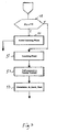
- FIG. 1 is a block diagram illustrating the primary functional components of a pacemaker system in accordance with this invention.
- Figure 2A is a simplified main flow diagram showing the steps pertinent to this invention which are taken each pacemaker cycle, and the relation of the VT prevention feature to the main operation routine;
- Figure 2B is a timing diagram illustrating determination of night, end of night, and the awakening period by a circadian pattern routine.
- FIG. 3 is an overview flow diagram illustrating the cyclical operations of the VT Prevention routine in accordance with this invention.
- Figure 4 is a simplified flow diagram illustrating the primary steps taken in carrying out the Learning Phase portion of the VT Prevention routine.
- Figure 5 is a simplified flow diagram illustrating the primary steps taken in carrying out the Ventricular Extra Systole analysis portion of the VT Prevention Routine.
- Figure 6 is a simplified flow diagram illustrating the primary steps taken in carrying out the Determine Intervention portion of the VT Prevention routine.
- a VP generator 15 provides pacing pulses, generated under control of block 20, for delivery through lead 16 to one or more ventricular electrodes 16E located in the patient's right ventricle.
- AP generator 18 provides atrial pacing pulses, also generated under control of block 20, for delivery through lead 19 to one or more atrial electrodes 19E located in the patient's right atrium. While not shown, it is understood that the invention is equally applicable to single chamber and to other multi-chamber configurations.
- Signals sensed by electrodes 16E are connected to QRS Sense circuit 24 which amplifies, the signals and provides V-Sense, or VS signals to signal processing block 27.
- Signals from ventricular electrodes 16E are also passed to T-Wave sense circuit 26, which provides T-Sense signals to block 27.
- Signals from atrial electrodes 19E are connected to P-Wave sense circuit 25, which outputs A-Sense, or AS signals to block 27.
- Block 27 suitably contains dedicated signal processing hardware; and includes an A-D converter for converting the signals into digital form.
- the QRS and T-wave template generation and comparison steps, referred to below, are performed wholly or in part in this circuitry.
- the digital signals from block 27 are transferred to block 20 for further processing and/or storage.
- Block 20 controls the pacemaker functions, e.g., the cyclical functions of setting and timing out escape intervals; receiving sensed signals from the patient's heart and resetting escape intervals based on those signals; and carrying out special functions such as the VT Prevention function of this invention.
- Block 20 preferably comprises a microprocessor and associated memory, shown at 21, for storing the required software routines.
- the memory 21 suitably includes dedicated RAM and ROM. Control parameters and values can be programmed from an external programmer through program receiver 29, in a known manner.
- the pacemaker can be programmed to operate in different modes.
- Sensor 28 may be used to provide a rate responsive parameter, e.g. activity, to be used alone or in combination with another parameter such as QT, in a manner known in the art.
- FIG. 2A there is provided a block diagram showing the place of the VT Prevention routine 34 within the overall main flow which is carried out cyclically.
- the main flow is entered cyclically at 30, where the pacemaker performs various bookkeeping and other steps.
- the spontaneous rate is determined; for a dual chamber system, decision rates are updated, in a manner as disclosed in U.S. Patent No. 5,247,930, assigned to the assignee of this invention.
- the pacemaker carries out a routine for determining the patient's circadian pattern, in order to determine "daytime” and "nighttime” for the patient, and to determine the patient's awakening period.
- the VT Prevention routine of this invention is performed, as discussed in detail below.
- the intervention rate controls the setting of the ventricular escape interval.
- These atrial and ventricular escape intervals are set at 35, and at 36 the pacemaker carries out the rest of the main flow, including ventricular event handling. QRS and T-wave sensing is also done at block 36.
- FIG. 2B there is shown a timing diagram for determining the patient's circadian pattern, and in particular for determining the awakening period.
- the referenced disclosure sets forth several embodiments of pacemaker routines for determining when the patient enters nighttime and when the patient enters daytime, by monitoring and evaluating changes in QT interval. Transition from nighttime to daytime is shown as representing the start of the awakening period.
- the awakening period may suitably be determined in several ways. For example, the awakening period may be determined as extending from the nighttime/daytime transition for a period of, e.g., one hour.
- the end of nighttime is suitably determined as the time when the QT interval drops below the variable QT_sleep, as shown in Figure 2B.
- nighttime may be of a fixed duration, with the start of night being determined when the QT interval stays above the QT_sleep variable for a night_criterion duration.
- the awakening period may be set so as to straddle the nighttime/daytime transition, e.g., from half an hour before to half an hour after. It is noted that other embodiments may be used for determining the end of night, e.g., by determining when the activity rate rises above a nighttime level.
- FIG. 3 there is shown a flow diagram of the specific steps taken in accordance with the VT prevention feature of this invention.
- the routine is run for determining the awakening period.
- the pacemaker determines whether the patient is in fact in the awakening period. If no, at 44 the intervention state is deactivated, and at 45 the pacemaker goes into the learning phase, the details of which are set forth in connection with Figure 4.
- the pacemaker goes on to process current information concerning the depolarization (QRS) and repolarization (T wave) waveforms.
- the pacemaker obtains the depolarization template for the current cycle, and compares it to the depolarization template which was generated during the learning phase. The difference is computed and stored as ⁇ 1.
- the pacemaker gets the current repolarization template and compares it with the stored repolarization template from the learning phase, and generates a ⁇ 2, which is representative of the difference.
- the pacemaker goes through a VES analysis, to obtain a measure ( ⁇ 3) of whether there has been a ventricular extra systole, and how close the coupling interval was to the patient's mean QT interval.
- the VES analysis is set forth in particular detail in Figure 5.
- the pacemaker goes to block 50, and determines whether intervention is indicated, based upon data gathered and generated at blocks 47, 48, and 49 above.
- the Determine Intervention routine is set forth in detail at Figure 6.
- the pacemaker determines whether intervention has been activated. If no, the routine exits, and the pacemaker continues to set the pacing escape intervals in a normal way. However, if yes, the routine branches to block 55, and determines whether the variable D is equal to or greater than a predetermined threshold.
- D is calculated in the Determine Intervention routine 50, and represents a summation of the respective ⁇ values calculated at blocks 47, 48, which are representative of refractorines dispersion; and also the ⁇ value calculated at 49, which represents the presence of a dangerous VES. The calculation of D is discussed in more detail in connection with Figure 6. If D is equal to or greater than threshold, at 57 the pacemaker determines whether the intervention rate remains less than the maximum intervention rate.
- intervention rate is incremented at 58; if no, intervention rate is at its maximum allowable value and the routine exits. If, at 55, D is not up to threshold, then at 60 it is determined whether the intervention rate is higher than the minimum intervention rate. If yes, at 61 intervention rate is decremented by subtracting a programmable drift value; if no, the intervention rate is as low as is allowed, and the routine exits.
- FIG. 4 there is shown a flow diagram of the learning phase routine 45, in accordance with this invention.
- this phase is entered when the patient is not in the awakening period.
- the pacemaker calculates a variable ⁇ 1 which constitutes the depolarization template then stored in memory, minus the current depolarization template for the just detected R wave.
- the wave signal data is placed into digital form by an A-D converter, which is part of the function provided by signal processor block 27.
- Obtaining waveform templates is well known in the art, and any suitable hardware or software arrangement can be used in this invention.
- digital samples are obtained representing the waveform amplitude along successive time increments, from the beginning of the wave to the end, and are stored.
- the respective waveform amplitude values are subtracted, and the difference is integrated over the time domain.
- the template generation and template difference calculations are performed by dedicated hardware, as shown at 27. However, any combination of hardware and software can be utilized.
- the depolarization template is adapted so as to be changed toward the most recently detected depolarization template.
- the functions are suitably carried out by the microprocessor of block 20.
- blocks 71, 72 and 74-76 represent corresponding steps for the repolarization template, which reflects the sensed T wave.
- the deviation ⁇ 2 is determined, by subtracting the just obtained repolarization wave from the stored repolarization template.
- the repolarization template is then adapted and stored at 76.
- FIG. 5 there is shown a flow diagram of the routine 49 for carrying out VES analysis. This is done, as discussed above, because VT is often initiated or preceded by one or more ventricular extra-systoles if the patient heart rate is low enough and the coupling interval is critical, i.e., VES occurs near or in the vulnerable phase. In this situation likewise, intervention may be indicated, so the pacemaker of this invention collects VES data which is included in the Determine Intervention routine.
- the routine branches to block 83, and sets ⁇ 3 (the deviation value corresponding to VES analysis) to zero. However, if there has been a VES, then it has to be determined how critical the VES is deemed, i.e., the deviation needs to be weighted.
- the pacemaker compares the coupling interval (the interval from the prior R wave to the VES) to the mean QT interval as stored. If the coupling interval minus the mean QT interval is less than or equal to a stored critical phase value, then the VES is deemed very critical, and at 90 ⁇ 3 is given a weighted VERY_CRITICAL value.
- the routine goes to 86 and determines whether there have been a predetermined number n VES occurrences in the last m intervals, where n and m are programmable numbers. If yes, the VES occurrences is deemed critical, and at block 87 ⁇ 3 is given a weighted CRITICAL value which is somewhat less than the VERY_CRITICAL value. If the answer at 86 is no, at 88 ⁇ 3 is given a LOW_CRITICAL weighting.
- the values assigned to ⁇ 3 include the weighting factor, such that the stored deviation is assumed to be accompanied by a weighting factor of 1 for the calculation which is carried out at block 77.
- intervention is activated at step 80, suitably by setting a flag to store the fact that intervention has been activated.
- intervention is activated at step 80, suitably by setting a flag to store the fact that intervention has been activated.
- the Intervention rate is decremented toward a lower limit.
- each cycle a direct measure of QTc or QT c can be obtained and a value of QT dispersion calculated and weighted; this weighted QT dispersion value is then added to the calculation made for determining intervention.
- each weighting factor can be programmed to vary within predetermined limits, so that weighting can be adapted in terms of known patient history.
Abstract
Description
- This invention relates to cardiac pacemaker systems and, more particularly, cardiac pacemaker systems with techniques for anticipating tachycardia and the capacity to automatically switch to a pacing modality designed to prevent Ventricular Tachycardia.
- The prevention of ventricular tachycardia and other dangerous arrhythmias has become a subject of intensive study and research. Ventricular tachycardia (VT) is a lethal arrhythmia which is known to frequently lead to sudden death, usually after progressing to ventricular fibrillation (VF). As a result, there have been many investigations into techniques for monitoring a patient's cardiac condition to determine when conditions indicate a likelihood of VT, and to otherwise continually assess the risk of VT and VF.
- It is known that QT interval, and in particular abnormalities of the QT interval, are associated with ventricular arrhythmias, e.g., in long QT syndromes and after myocardia infarction. See "Diurnal Variation of the QT Interval - Influence of the Autonomic Nervous System," Bexton et al., British Heart J., 1986; 55:253-8. Thus, the QT interval of the surface EKG is accepted as an indirect measure of patient myocardial depolarization and repolarization. It is known that QT is longer during sleep, and in fact QT corrected for rate (QTc) is also longer during sleep. Further, it has been noted that QTc interval and QTc variability reach peak shortly after awakening hours, which may reflect increased automatic instability during early waking hours; and further that the time of the peak value corresponds to the period of reported increased vulnerability to ventricular tachycardia and sudden cardiac death. Molnar et al., J. Am. Coll. Cardiology, 1996 Jan., 27:1, 76-83. See also Christenson et al., PACE, Vol. 19, September 1996, 1296-1393, stating that QTc exhibits significant diurnal variability. The literature suggests that there are significant changes in the autonomic system during sleep, with either an increase in para-sympathetic tone, or an increase in sympathetic activity, or both. There is also a diurnal variation in circulating catecholamines, and specifically the catecholamine level drops during the night. These factors are known to influence repolarization, nighttime variations of which are reflected in the lengthening QT interval, and lengthened QTc. Other investigations have looked into the temporal and spatial distribution of QT intervals, and suggest that QT dispersion (QTd), measured as the difference between the maximal and minimal value of QT duration, can be associated with increased risk of ventricular tachycardia and sudden cardiac death. Accordingly, the literature presently suggests that both QT interval prolongation and increased QT dispersion (refractory dispersion), or dispersion of the repolarization duration, are important reflectors of the risk of an incipient ventricular tachycardia.
- This invention is responsive to the need to address the increased vulnerability to attacks of VT during or just after the waking period, and utilize the fact that the awakening period is characterized by observable variabilities of the depolarization and repolarization waves and the QT duration. In particular, the invention meets the need for a pacemaker which incorporates the capacity to monitor the diurnal heart pattern, particularly changes of the QRS-T waveform during the awakening period, so as to provide an indication of a risk of VT. A pacemaker in accordance with this invention also automatically provides for a controlled pacing response designed to prevent the onset of VT during the vulnerable awakening period.
- It is a primary object of this invention to provide a pacemaker system having diurnal pattern detection for determining, on the basis of monitored QT interval, a period of patient awakening which covers the period when cardiac patients are most vulnerable to onset of VT; and to combine in the pacemaker system a continuous determination throughout the awakening period of data indicative of the likelihood of incipient VT, combined with a pacing response mode for preventing VT when it is determined to be likely.
- In accordance with the above objects, there is provided a cardiac pacemaker system for pacing a patient, having ventricular pacing (VP) means for generating and delivering ventricular pacing pulses to a patient's ventricle, ventricular sensing (VS) means for sensing ventricular QRS and T waves, rate means for determining the patient's spontaneous heart rate, and control means for controlling when said VP means generates and delivers ventricular pacing pulses and the pacing rate of such pulses, wherein said control means further comprises VT prevention means for controlling said VP means to deliver pacing pulses at a rate overriding the patient's spontaneous rate when a threshold of refractory dispersion is detected during patient awakening, said VT prevention means comprising:
- awakening means for determining an awakening period when the patient is awakening;
- depolarization means for determining a first measure of dispersion of the patient's depolarization wave during awakening;
- repolarization means for determining a second measure of dispersion of the patient's repolarization wave during awakening; and
- intervention means for controlling said VP means to generate and deliver pacing pulses at an intervention rate that overrides the patient's spontaneous rate as a function of said first and second measures.
-
- In accordance with a second aspect, there is provided cardiac pacemaker system for pacing a patient, having VP means for generating and delivering ventricular pacing pulses to a patient's ventricle, VS means for sensing ventricular QRS and T waves, rate means for determining the patient's spontaneous heart rate, and control means for controlling when said VP means generates and delivers ventricular pacing pulses and the pacing rate of such pulses, wherein said control means further comprises VT prevention means for controlling said VP means to deliver pacing pulses at a rate overriding the patient's spontaneous rate when a threshold of refractory dispersion is detected during patient awakening, said VT prevention means comprising:
- awakening means for determining an awakening period when the patient is awakening;
- dispersion data means for determining during said awakening period data representative of ventricular refractory dispersion;
- threshold means for determining from said data when patient refractory dispersion exceeds said threshold; and
- overdrive control means for setting pacing rate at an intervention rate which is adjusted as a function of said data.
-
- In accordance with a third aspect, there is provided a pacemaker system for pacing a patient's heart, having VP means for generating and delivering pacing pulses to a patient's ventricle, rate control means for controlling the rate of said pacing pulses, and said rate control means having VT prevention means for controlling said rate to an intervention rate when said patient has a detected measure of refractory dispersion during awakening, said VT prevention means comprising:
- awakening means for determining when said patient is in a state of awakening;
- dispersion means for determining a measure of dispersion of ventricular refractoriness; and
- intervention means for setting and continually adjusting said intervention rate as a function of said dispersion measure.
-
- Preferred embodiments of the invention will now be described, by way of example only, with reference to the accompanying drawings.
- Figure 1 is a block diagram illustrating the primary functional components of a pacemaker system in accordance with this invention.
- Figure 2A is a simplified main flow diagram showing the steps pertinent to this invention which are taken each pacemaker cycle, and the relation of the VT prevention feature to the main operation routine; Figure 2B is a timing diagram illustrating determination of night, end of night, and the awakening period by a circadian pattern routine.
- Figure 3 is an overview flow diagram illustrating the cyclical operations of the VT Prevention routine in accordance with this invention.
- Figure 4 is a simplified flow diagram illustrating the primary steps taken in carrying out the Learning Phase portion of the VT Prevention routine.
- Figure 5 is a simplified flow diagram illustrating the primary steps taken in carrying out the Ventricular Extra Systole analysis portion of the VT Prevention Routine.
- Figure 6 is a simplified flow diagram illustrating the primary steps taken in carrying out the Determine Intervention portion of the VT Prevention routine.
- Referring now to Figure 1, there is shown a block diagram of the primary functional components of an illustrative pacemaker system for use in this invention. A
VP generator 15 provides pacing pulses, generated under control ofblock 20, for delivery through lead 16 to one or moreventricular electrodes 16E located in the patient's right ventricle. Likewise, AP generator 18 provides atrial pacing pulses, also generated under control ofblock 20, for delivery through lead 19 to one or moreatrial electrodes 19E located in the patient's right atrium. While not shown, it is understood that the invention is equally applicable to single chamber and to other multi-chamber configurations. Signals sensed byelectrodes 16E are connected toQRS Sense circuit 24 which amplifies, the signals and provides V-Sense, or VS signals tosignal processing block 27. Signals fromventricular electrodes 16E are also passed to T-Wave sense circuit 26, which provides T-Sense signals to block 27. Signals fromatrial electrodes 19E are connected to P-Wave sense circuit 25, which outputs A-Sense, or AS signals to block 27. -
Block 27 suitably contains dedicated signal processing hardware; and includes an A-D converter for converting the signals into digital form. The QRS and T-wave template generation and comparison steps, referred to below, are performed wholly or in part in this circuitry. The digital signals fromblock 27 are transferred toblock 20 for further processing and/or storage.Block 20 controls the pacemaker functions, e.g., the cyclical functions of setting and timing out escape intervals; receiving sensed signals from the patient's heart and resetting escape intervals based on those signals; and carrying out special functions such as the VT Prevention function of this invention.Block 20 preferably comprises a microprocessor and associated memory, shown at 21, for storing the required software routines. - The
memory 21 suitably includes dedicated RAM and ROM. Control parameters and values can be programmed from an external programmer through program receiver 29, in a known manner. The pacemaker can be programmed to operate in different modes. Sensor 28 may be used to provide a rate responsive parameter, e.g. activity, to be used alone or in combination with another parameter such as QT, in a manner known in the art. - Referring now to Figure 2A there is provided a block diagram showing the place of the VT Prevention routine 34 within the overall main flow which is carried out cyclically. The main flow is entered cyclically at 30, where the pacemaker performs various bookkeeping and other steps. At 31, the spontaneous rate is determined; for a dual chamber system, decision rates are updated, in a manner as disclosed in U.S. Patent No. 5,247,930, assigned to the assignee of this invention. At 33, the pacemaker carries out a routine for determining the patient's circadian pattern, in order to determine "daytime" and "nighttime" for the patient, and to determine the patient's awakening period. Then, at 34, the VT Prevention routine of this invention is performed, as discussed in detail below. If the result of this routine is the setting of an intervention rate in response to a determination of onset of VT, the intervention rate controls the setting of the ventricular escape interval. These atrial and ventricular escape intervals are set at 35, and at 36 the pacemaker carries out the rest of the main flow, including ventricular event handling. QRS and T-wave sensing is also done at
block 36. - Referring now to Figure 2B, there is shown a timing diagram for determining the patient's circadian pattern, and in particular for determining the awakening period. Reference is made to U.S. patent application S.N. 08/800,413, filed February 14, 1997, "Pacemaker With Automatic Lower Rate Limit Drop". The referenced disclosure sets forth several embodiments of pacemaker routines for determining when the patient enters nighttime and when the patient enters daytime, by monitoring and evaluating changes in QT interval. Transition from nighttime to daytime is shown as representing the start of the awakening period. The awakening period may suitably be determined in several ways. For example, the awakening period may be determined as extending from the nighttime/daytime transition for a period of, e.g., one hour. In this arrangement, the end of nighttime is suitably determined as the time when the QT interval drops below the variable QT_sleep, as shown in Figure 2B. Alternatively, in another embodiment, nighttime may be of a fixed duration, with the start of night being determined when the QT interval stays above the QT_sleep variable for a night_criterion duration. In this case, the awakening period may be set so as to straddle the nighttime/daytime transition, e.g., from half an hour before to half an hour after. It is noted that other embodiments may be used for determining the end of night, e.g., by determining when the activity rate rises above a nighttime level.
- Referring now to Figure 3, there is shown a flow diagram of the specific steps taken in accordance with the VT prevention feature of this invention. At 40, the routine is run for determining the awakening period. At 41 the pacemaker determines whether the patient is in fact in the awakening period. If no, at 44 the intervention state is deactivated, and at 45 the pacemaker goes into the learning phase, the details of which are set forth in connection with Figure 4.
- If the patient is in the awakening period, the pacemaker goes on to process current information concerning the depolarization (QRS) and repolarization (T wave) waveforms. At 47, the pacemaker obtains the depolarization template for the current cycle, and compares it to the depolarization template which was generated during the learning phase. The difference is computed and stored as Δ1. Likewise, at
step 48, the pacemaker gets the current repolarization template and compares it with the stored repolarization template from the learning phase, and generates a Δ2, which is representative of the difference. Then, atblock 49, the pacemaker goes through a VES analysis, to obtain a measure (Δ3) of whether there has been a ventricular extra systole, and how close the coupling interval was to the patient's mean QT interval. The VES analysis is set forth in particular detail in Figure 5. Following this, the pacemaker goes to block 50, and determines whether intervention is indicated, based upon data gathered and generated atblocks - Still referring to Figure 3, at block 54, the pacemaker determines whether intervention has been activated. If no, the routine exits, and the pacemaker continues to set the pacing escape intervals in a normal way. However, if yes, the routine branches to block 55, and determines whether the variable D is equal to or greater than a predetermined threshold. D is calculated in the Determine
Intervention routine 50, and represents a summation of the respective Δ values calculated atblocks - Referring now to Figure 4, there is shown a flow diagram of the
learning phase routine 45, in accordance with this invention. As discussed in connection with Figure 3, this phase is entered when the patient is not in the awakening period. At 62, the pacemaker calculates a variable Δ1 which constitutes the depolarization template then stored in memory, minus the current depolarization template for the just detected R wave. In obtaining a template, the wave signal data is placed into digital form by an A-D converter, which is part of the function provided bysignal processor block 27. Obtaining waveform templates is well known in the art, and any suitable hardware or software arrangement can be used in this invention. In a preferred embodiment, digital samples are obtained representing the waveform amplitude along successive time increments, from the beginning of the wave to the end, and are stored. In determining the Δ difference, the respective waveform amplitude values are subtracted, and the difference is integrated over the time domain. In a preferred embodiment, the template generation and template difference calculations are performed by dedicated hardware, as shown at 27. However, any combination of hardware and software can be utilized. - Next, at 64, it is determined whether the Δ1 value is small. The reason for making this determination is that large variations during the learning phase suggest that the signal is not stable enough to be a reference during the awakening period. Consequently, if the deviation found at 64 is statistically small (indicating stability), at 66 a weighting factor W1 is increased; if the deviation is not statistically small, then at 68 the W1 is decreased. These weighting factors are utilized in the subsequent determination of intervention in
routine 50. Next, atblock 70, the depolarization template is adapted so as to be changed toward the most recently detected depolarization template. This can be done, e.g., by matching the minimum values and slopes of the depolarization template and the new QRS wave, and adjusting each sample of the template incrementally toward the samples of the new QRS. The functions are suitably carried out by the microprocessor ofblock 20. - Still referring to Figure 4, blocks 71, 72 and 74-76 represent corresponding steps for the repolarization template, which reflects the sensed T wave. At 71, the deviation Δ2 is determined, by subtracting the just obtained repolarization wave from the stored repolarization template. At 72, it is determined whether the deviation is small, representing a stable signal. If yes, weighting factor W2 is increased at 74; if no, W2 is decreased at 75. The repolarization template is then adapted and stored at 76.
- Referring now to Figure 5, there is shown a flow diagram of the routine 49 for carrying out VES analysis. This is done, as discussed above, because VT is often initiated or preceded by one or more ventricular extra-systoles if the patient heart rate is low enough and the coupling interval is critical, i.e., VES occurs near or in the vulnerable phase. In this situation likewise, intervention may be indicated, so the pacemaker of this invention collects VES data which is included in the Determine Intervention routine.
- At
block 82, it is determined whether there has been a VES. If no, the routine branches to block 83, and sets Δ3 (the deviation value corresponding to VES analysis) to zero. However, if there has been a VES, then it has to be determined how critical the VES is deemed, i.e., the deviation needs to be weighted. At 85, the pacemaker compares the coupling interval (the interval from the prior R wave to the VES) to the mean QT interval as stored. If the coupling interval minus the mean QT interval is less than or equal to a stored critical phase value, then the VES is deemed very critical, and at 90 Δ3 is given a weighted VERY_CRITICAL value. However, if the answer at 85 is no, then the routine goes to 86 and determines whether there have been a predetermined number n VES occurrences in the last m intervals, where n and m are programmable numbers. If yes, the VES occurrences is deemed critical, and at block 87 Δ3 is given a weighted CRITICAL value which is somewhat less than the VERY_CRITICAL value. If the answer at 86 is no, at 88 Δ3 is given a LOW_CRITICAL weighting. At routine 49, the values assigned to Δ3 include the weighting factor, such that the stored deviation is assumed to be accompanied by a weighting factor of 1 for the calculation which is carried out at block 77. - Referring now to Figure 6, there is shown a flow diagram of the
Determined Intervention routine 50. At step 77, the pacemaker determines the total deviation D, which is calculated by taking the sum of all the separate deviations, each multiplied by its respective weighting factor W. In the preferred embodiment as illustrated, there are three different deviations determined, so the summation is from i = 1 to i = 3. Thus, each cycle the summation constitutes Δ1 multiplied by the current value of W1; Δ2 multiplied by the current value of W2, and the determined value of .3, where the weighting factor is 1 since the value of Δ3 has already been calculated to reflect appropriate weighting. At 78, it is determined whether the current value D is greater than or equal to threshold. If no, intervention is not indicated and the routine exits. However, if D is greater than or equal to the programmed threshold, then intervention is activated atstep 80, suitably by setting a flag to store the fact that intervention has been activated. As seen in Figure 3, once intervention has been activated, it is not deactivated until the awakening period is over, at which time the pacemaker proceeds to block 44 and deactivates intervention. As per the above discussion of Figure 3, if D drops below threshold when Intervention is activated, the Intervention rate is decremented toward a lower limit. - Recapitulating, and referring to Figure 3, it is seen that during normal periods outside of the awakening period, both daytime and nighttime, the pacemaker is continually adapting the depolarization and repolarization templates in the learning phase. When the patient is in the awakening period, data represented by deviation values Δ1, Δ2 and Δ3 are obtained at
blocks - It is noted that while three separate deviation measurements are illustrated in the preferred embodiments, additional data can be collected, and weighted accordingly. Thus, each cycle a direct measure of QTc or QTc can be obtained and a value of QT dispersion calculated and weighted; this weighted QT dispersion value is then added to the calculation made for determining intervention. Additionally, each weighting factor can be programmed to vary within predetermined limits, so that weighting can be adapted in terms of known patient history.
Claims (20)
- A cardiac pacemaker system for pacing a patient, having ventricular pacing (VP) means for generating and delivering ventricular pacing pulses to a patient's ventricle, ventricular sensing (VS) means for sensing ventricular QRS and T waves, rate means for determining the patient's spontaneous heart rate, and control means for controlling when said VP means generates and delivers ventricular pacing pulses and the pacing rate of such pulses, wherein said control means further comprises VT prevention means for controlling said VP means to deliver pacing pulses at a rate overriding the patient's spontaneous rate when a threshold of refractory dispersion is detected during patient awakening, said VT prevention means comprising:awakening means for determining an awakening period when the patient is awakening;depolarization means for determining a first measure of dispersion of the patient's depolarization wave during awakening;repolarization means for determining a second measure of dispersion of the patient's repolarization wave during awakening; andintervention means for controlling said VP means to generate and deliver pacing pulses at an intervention rate that overrides the patient's spontaneous rate as a function of said first and second measures.
- The system as described in claim 1, wherein said VT prevention means comprises learning means operative during the patient's non-awakening period for generating and storing reference signals representative of the patient's depolarization and repolarization waves during said non-awakening period, and current means for obtaining current signals representative of said depolarization and repolarization signals during said awakening period.
- The system as described in claim 2, wherein said learning means comprises template means for obtaining and storing reference depolarization and repolarization templates, and said current means comprises current template means for cyclically obtaining and storing current depolarization and repolarization templates.
- The system as described in claim 3, wherein said depolarization means comprises first comparison means for comparing the current depolarization template with said reference depolarization template to obtain a depolarization deviation value, and said repolarization means comprises second comparison means for comparing the current repolarization template with said reference repolarization template to obtain a repolarization deviation value.
- The system as described in claim 4, wherein said depolarization means comprises first weighting means for weighting said depolarization deviation value as a function of depolarization wave stability to obtain said first measure, and said repolarization means comprises second weighting means for weighting said repolarization deviation value as a function of repolarization wave stability to obtain said second measure.
- The system as described in any preceding claim, further comprising VES means for obtaining data representative of each patient ventricular extra systole and its criticality with respect to the ventricular vulnerable period.
- The system as described in any preceding claim, wherein said VT prevention means further comprises means operative during said awakening period for accumulating weighted data representative of depolarization dispersion and repolarization dispersion.
- A cardiac pacemaker system for pacing a patient, having VP means for generating and delivering ventricular pacing pulses to a patient's ventricle, VS means for sensing ventricular QRS and T waves, rate means for determining the patient's spontaneous heart rate, and control means for controlling when said VP means generates and delivers ventricular pacing pulses and the pacing rate of such pulses, wherein said control means further comprises VT prevention means for controlling said VP means to deliver pacing pulses at a rate overriding the patient's spontaneous rate when a threshold of refractory dispersion is detected during patient awakening, said VT prevention means comprising:awakening means for determining an awakening period when the patient is awakening;dispersion data means for determining during said awakening period data representative of ventricular refractory dispersion;threshold means for determining from said data when patient refractory dispersion exceeds said threshold; andoverdrive control means for setting pacing rate at an intervention rate which is adjusted as a function of said data.
- The system as described in claim 8, wherein said dispersion data means comprises first means for obtaining data representative of a first predetermined parameter of the QRS-T wave signals and second means for obtaining data representative of a second predetermined parameter of the QRS-T wave signals.
- A pacemaker system for pacing a patient's heart, having VP means for generating and delivering pacing pulses to a patient's ventricle, rate control means for controlling the rate of said pacing pulses, and said rate control means having VT prevention means for controlling said rate to an intervention rate when said patient has a detected measure of refractory dispersion during awakening, said VT prevention means comprising:awakening means for determining when said patient is in a state of awakening;dispersion means for determining a measure of dispersion of ventricular refractoriness; andintervention means for setting and continually adjusting said intervention rate as a function of said dispersion measure.
- The system as described in claim 10, wherein said dispersion means comprises means for cyclically obtaining a measure of the variability of the patient's QRS during the awakening state.
- The system as described in claim 10, wherein said dispersion means comprises means for obtaining a reference measure of the patient's QRS waveform when the patient is not awakening, means for obtaining a current measure of the patient's current QRS waveform during awakening, and comparing means for comparing said current measure with said reference measure.
- The system as described in claim 10, wherein said dispersion means comprises means for cyclically obtaining a measure of the variability of the patient's T wave during the awakening state.
- The system as described in claim 10, wherein said dispersion means comprises means for obtaining a reference measure of the patient's T wave when the patient is not awakening, means for obtaining a current measure of the patient's current T wave during awakening, and comparing means for comparing said current measure with said reference measure.
- The system as described in claim 10, wherein said dispersion means comprises QT means for cyclically obtaining a measure of the variability of the patient's QT interval during the awakening state.
- The system as described in any of claims 10 to 15, further comprising VES means for detecting when a ventricular extra systole occurs during the awakening state that is close to the end of the ventricular refractory period, and wherein said intervention means comprises determining means for determining said intervention rate as a function of said VES detecting.
- The system as described in claim 10, wherein said dispersion means comprises means for obtaining at least two respective measures of said dispersion, and accumulating means for accumulating said measures, and wherein said intervention means adjusts said intervention rate as a function of said accumulated measures.
- The system as described in any of claims 10 to 17, comprising rate means for determining the patient's spontaneous rate, and wherein said VT prevention means comprises means for setting said intervention right higher than said spontaneous rate, whereby said pacemaker overdrives the patient's spontaneous rate during said awakening state.
- The system as described in claim 17, wherein said intervention means comprises increment means for incrementing said intervention rate when said accumulated measures increase, and for decrementing said intervention rate when said accumulated measures decrease.
- The system as described in claim 10, wherein said dispersion means comprises data means for cyclically obtaining data representative of ventricular refractoriness.
Applications Claiming Priority (2)
| Application Number | Priority Date | Filing Date | Title |
|---|---|---|---|
| US237815 | 1999-01-27 | ||
| US09/237,815 US6370431B1 (en) | 1998-10-26 | 1999-01-27 | Pacemaker system for preventing ventricular tachycardia |
Publications (3)
| Publication Number | Publication Date |
|---|---|
| EP1023918A2 true EP1023918A2 (en) | 2000-08-02 |
| EP1023918A3 EP1023918A3 (en) | 2001-09-12 |
| EP1023918B1 EP1023918B1 (en) | 2006-11-22 |
Family
ID=22895315
Family Applications (1)
| Application Number | Title | Priority Date | Filing Date |
|---|---|---|---|
| EP00101601A Expired - Lifetime EP1023918B1 (en) | 1999-01-27 | 2000-01-27 | Pacemaker system with diurnal pattern controlled overdrive for prevention of tachycardia |
Country Status (4)
| Country | Link |
|---|---|
| US (1) | US6370431B1 (en) |
| EP (1) | EP1023918B1 (en) |
| AT (1) | ATE345836T1 (en) |
| DE (1) | DE60031900T2 (en) |
Cited By (1)
| Publication number | Priority date | Publication date | Assignee | Title |
|---|---|---|---|---|
| WO2005056107A1 (en) * | 2003-12-03 | 2005-06-23 | Medtronic, Inc. | Method and apparatus for predicting arrhythmias using diurnal heart rate |
Families Citing this family (31)
| Publication number | Priority date | Publication date | Assignee | Title |
|---|---|---|---|---|
| US6223078B1 (en) | 1999-03-12 | 2001-04-24 | Cardiac Pacemakers, Inc. | Discrimination of supraventricular tachycardia and ventricular tachycardia events |
| US6312388B1 (en) * | 1999-03-12 | 2001-11-06 | Cardiac Pacemakers, Inc. | Method and system for verifying the integrity of normal sinus rhythm templates |
| US6449503B1 (en) * | 1999-07-14 | 2002-09-10 | Cardiac Pacemakers, Inc. | Classification of supraventricular and ventricular cardiac rhythms using cross channel timing algorithm |
| US7349734B2 (en) * | 2000-05-15 | 2008-03-25 | Cardiac Pacemakers, Inc. | Method and apparatus for delivering defibrillation shock therapy while reducing electrical dispersion due to ventricular conduction disorder |
| US7076299B2 (en) * | 2002-03-28 | 2006-07-11 | Tran Thong | Method and apparatus for preventing heart tachyarrhythmia |
| US7047067B2 (en) * | 2002-05-31 | 2006-05-16 | Uab Research Foundation | Apparatus, methods, and computer program products for evaluating a risk of cardiac arrhythmias from restitution properties |
| US7130686B1 (en) * | 2002-07-01 | 2006-10-31 | Pacesetter, Inc. | Selection of preventative arrhythmia therapy based on patient specific histogram data |
| US6970743B2 (en) * | 2002-08-30 | 2005-11-29 | Pacesetter, Inc. | System and method for treating abnormal ventricular activation-recovery time |
| US7031764B2 (en) * | 2002-11-08 | 2006-04-18 | Cardiac Pacemakers, Inc. | Cardiac rhythm management systems and methods using multiple morphology templates for discriminating between rhythms |
| US8712549B2 (en) * | 2002-12-11 | 2014-04-29 | Proteus Digital Health, Inc. | Method and system for monitoring and treating hemodynamic parameters |
| WO2004066817A2 (en) * | 2003-01-24 | 2004-08-12 | Proteus Biomedical Inc. | Methods and systems for measuring cardiac parameters |
| JP4557964B2 (en) * | 2003-01-24 | 2010-10-06 | プロテウス バイオメディカル インコーポレイテッド | Method and apparatus for improving cardiac pacing |
| JP4528766B2 (en) * | 2003-01-24 | 2010-08-18 | プロテウス バイオメディカル インコーポレイテッド | System for remote hemodynamic monitoring |
| US7328066B1 (en) * | 2003-03-28 | 2008-02-05 | Pacesetter, Inc. | Implantable cardiac stimulation device, system and method that identifies and prevents impending arrhythmias of the atria |
| EP1641523A4 (en) * | 2003-07-03 | 2007-06-27 | Univ New York | System and method for assessment of cardiac electrophysiologic stability and modulation of cardiac oscillations |
| US8027722B1 (en) * | 2003-10-17 | 2011-09-27 | Pacesetter, Inc. | Multifocal PVC detection for prevention of arrhythmias |
| EP1799101A4 (en) * | 2004-09-02 | 2008-11-19 | Proteus Biomedical Inc | Methods and apparatus for tissue activation and monitoring |
| EP1871470A4 (en) * | 2005-03-31 | 2011-06-01 | Proteus Biomedical Inc | Automated optimization of multi-electrode pacing for cardiac resynchronization |
| US7881786B2 (en) * | 2005-04-29 | 2011-02-01 | Medtronic, Inc. | Suppression of high rate pacing for reducing myocardial ischemic irritability |
| US20090299447A1 (en) * | 2005-07-01 | 2009-12-03 | Marc Jensen | Deployable epicardial electrode and sensor array |
| US7983751B2 (en) * | 2005-08-12 | 2011-07-19 | Proteus Biomedical, Inc. | Measuring conduction velocity using one or more satellite devices |
| JP2009521276A (en) * | 2005-12-22 | 2009-06-04 | プロテウス バイオメディカル インコーポレイテッド | Implantable integrated circuit |
| US7765002B2 (en) * | 2006-12-08 | 2010-07-27 | Cardiac Pacemakers, Inc. | Rate aberrant beat selection and template formation |
| US8473069B2 (en) * | 2008-02-28 | 2013-06-25 | Proteus Digital Health, Inc. | Integrated circuit implementation and fault control system, device, and method |
| EP2358429A4 (en) * | 2008-12-02 | 2013-05-29 | Proteus Digital Health Inc | Analyzer compatible communication protocol |
| EP2414036A4 (en) * | 2009-04-02 | 2013-02-20 | Proteus Digital Health Inc | Method and apparatus for implantable lead |
| JP2012525206A (en) | 2009-04-29 | 2012-10-22 | プロテウス バイオメディカル インコーポレイテッド | Method and apparatus for leads for implantable devices |
| US8786049B2 (en) | 2009-07-23 | 2014-07-22 | Proteus Digital Health, Inc. | Solid-state thin-film capacitor |
| US8718770B2 (en) | 2010-10-21 | 2014-05-06 | Medtronic, Inc. | Capture threshold measurement for selection of pacing vector |
| US8355784B2 (en) | 2011-05-13 | 2013-01-15 | Medtronic, Inc. | Dynamic representation of multipolar leads in a programmer interface |
| US9597525B2 (en) * | 2015-05-06 | 2017-03-21 | Medtronic, Inc. | T-wave oversensing rejection |
Citations (2)
| Publication number | Priority date | Publication date | Assignee | Title |
|---|---|---|---|---|
| US5247930A (en) | 1992-02-04 | 1993-09-28 | Vitatron Medical, B.V. | Dual chamber pacing system with dynamic physiological tracking and method of timing delivered stimulus for optimized synchronous pacing |
| US5861011A (en) | 1997-02-14 | 1999-01-19 | Vitatron Medical, B.V. | Pacemaker with automatic lower rate limit drop |
Family Cites Families (10)
| Publication number | Priority date | Publication date | Assignee | Title |
|---|---|---|---|---|
| US5042497A (en) * | 1990-01-30 | 1991-08-27 | Cardiac Pacemakers, Inc. | Arrhythmia prediction and prevention for implanted devices |
| FR2669523B1 (en) * | 1990-11-23 | 1997-06-06 | Fred Zacouto | HEART FAILURE PREVENTION DEVICE |
| US5271393A (en) | 1991-05-06 | 1993-12-21 | Telectronics Pacing Systems, Inc. | Pacemaker employing antitachyarrhythmia prevention based on ventricular gradient |
| US5560368A (en) * | 1994-11-15 | 1996-10-01 | Berger; Ronald D. | Methodology for automated QT variability measurement |
| US6058328A (en) * | 1996-08-06 | 2000-05-02 | Pacesetter, Inc. | Implantable stimulation device having means for operating in a preemptive pacing mode to prevent tachyarrhythmias and method thereof |
| US5782887A (en) * | 1997-03-26 | 1998-07-21 | Vitatron Medical, B.V. | Pacemaker system with PAC tracking based on QT data |
| US5978711A (en) * | 1998-02-23 | 1999-11-02 | Vivatron Medical, B.V. | Pacemaker system with improved learning capability for adapting rate response function |
| US5967995A (en) * | 1998-04-28 | 1999-10-19 | University Of Pittsburgh Of The Commonwealth System Of Higher Education | System for prediction of life-threatening cardiac arrhythmias |
| US5991659A (en) * | 1998-09-30 | 1999-11-23 | Vitatron Medical, B.V. | Pacing system with full range sudden rate drop detection and responsive pacing intervention |
| US6161041A (en) * | 1998-10-26 | 2000-12-12 | Vitatron Medical B. V. | Pacemaker system with diurnal pattern controlled overdrive for prevention of tachycardia |
-
1999
- 1999-01-27 US US09/237,815 patent/US6370431B1/en not_active Expired - Fee Related
-
2000
- 2000-01-27 DE DE60031900T patent/DE60031900T2/en not_active Expired - Lifetime
- 2000-01-27 AT AT00101601T patent/ATE345836T1/en not_active IP Right Cessation
- 2000-01-27 EP EP00101601A patent/EP1023918B1/en not_active Expired - Lifetime
Patent Citations (2)
| Publication number | Priority date | Publication date | Assignee | Title |
|---|---|---|---|---|
| US5247930A (en) | 1992-02-04 | 1993-09-28 | Vitatron Medical, B.V. | Dual chamber pacing system with dynamic physiological tracking and method of timing delivered stimulus for optimized synchronous pacing |
| US5861011A (en) | 1997-02-14 | 1999-01-19 | Vitatron Medical, B.V. | Pacemaker with automatic lower rate limit drop |
Cited By (2)
| Publication number | Priority date | Publication date | Assignee | Title |
|---|---|---|---|---|
| WO2005056107A1 (en) * | 2003-12-03 | 2005-06-23 | Medtronic, Inc. | Method and apparatus for predicting arrhythmias using diurnal heart rate |
| US7313439B2 (en) | 2003-12-03 | 2007-12-25 | Medtronic, Inc. | Method and apparatus for predicting arrhythmias using diurnal heart rate |
Also Published As
| Publication number | Publication date |
|---|---|
| US6370431B1 (en) | 2002-04-09 |
| EP1023918B1 (en) | 2006-11-22 |
| EP1023918A3 (en) | 2001-09-12 |
| DE60031900T2 (en) | 2007-09-20 |
| ATE345836T1 (en) | 2006-12-15 |
| DE60031900D1 (en) | 2007-01-04 |
Similar Documents
| Publication | Publication Date | Title |
|---|---|---|
| EP1023918B1 (en) | Pacemaker system with diurnal pattern controlled overdrive for prevention of tachycardia | |
| US6161041A (en) | Pacemaker system with diurnal pattern controlled overdrive for prevention of tachycardia | |
| EP1494582B1 (en) | Method for prediciting recurring ventricular arrhythmias | |
| US8437842B2 (en) | Method and apparatus for detecting and discriminating tachycardia | |
| EP2563468B1 (en) | Apparatus for detecting and discriminating tachycardia | |
| US20040064062A1 (en) | Method for determining a metric of non-sustained arrhythmia occurrence for use in arrhythmia prediction and automatic adjustment of arrhythmia detection parameters | |
| EP2563467B1 (en) | System of dual egm sensing and heart rate estimation in implanted cardiac devices | |
| US6238422B1 (en) | Pacemaker system with therapy for minimizing risk of morning myocardial infarctions or arrhythmias | |
| WO2011136923A1 (en) | Method and apparatus for detecting and discriminating tachycardia | |
| US8406872B2 (en) | Method and apparatus for detecting and discriminating tachycardia | |
| US8543198B2 (en) | Method and apparatus for detecting and discriminating tachycardia | |
| WO2011136916A1 (en) | Method and apparatus for detecting and discriminating tachycardia | |
| WO2011136951A1 (en) | Method and apparatus for detecting and discriminating tachycardia | |
| US7313439B2 (en) | Method and apparatus for predicting arrhythmias using diurnal heart rate | |
| US20010007948A1 (en) | Placemaker system for preventing ventricular tachycardia | |
| EP2563473B1 (en) | Apparatus for detecting and discriminating tachycardia | |
| WO2011136950A1 (en) | Apparatus for detecting and discriminating tachycardia | |
| US8301235B2 (en) | Method and apparatus for detecting and discriminating tachycardia | |
| WO2011136926A1 (en) | Method and apparatus for detecting and discriminating tachycardia | |
| WO2011136920A1 (en) | Method and apparatus for detecting and discriminating tachycardia |
Legal Events
| Date | Code | Title | Description |
|---|---|---|---|
| PUAI | Public reference made under article 153(3) epc to a published international application that has entered the european phase |
Free format text: ORIGINAL CODE: 0009012 |
|
| AK | Designated contracting states |
Kind code of ref document: A2 Designated state(s): AT BE CH CY DE DK ES FI FR GB GR IE IT LI LU MC NL PT SE |
|
| AX | Request for extension of the european patent |
Free format text: AL;LT;LV;MK;RO;SI |
|
| PUAL | Search report despatched |
Free format text: ORIGINAL CODE: 0009013 |
|
| AK | Designated contracting states |
Kind code of ref document: A3 Designated state(s): AT BE CH CY DE DK ES FI FR GB GR IE IT LI LU MC NL PT SE |
|
| AX | Request for extension of the european patent |
Free format text: AL;LT;LV;MK;RO;SI |
|
| RIC1 | Information provided on ipc code assigned before grant |
Free format text: 7A 61N 1/368 A, 7A 61N 1/362 B |
|
| 17P | Request for examination filed |
Effective date: 20011217 |
|
| AKX | Designation fees paid |
Free format text: AT BE CH CY DE DK ES FI FR GB GR IE IT LI LU MC NL PT SE |
|
| RAP1 | Party data changed (applicant data changed or rights of an application transferred) |
Owner name: MEDTRONIC, INC. |
|
| 17Q | First examination report despatched |
Effective date: 20040909 |
|
| GRAP | Despatch of communication of intention to grant a patent |
Free format text: ORIGINAL CODE: EPIDOSNIGR1 |
|
| GRAS | Grant fee paid |
Free format text: ORIGINAL CODE: EPIDOSNIGR3 |
|
| GRAA | (expected) grant |
Free format text: ORIGINAL CODE: 0009210 |
|
| AK | Designated contracting states |
Kind code of ref document: B1 Designated state(s): AT BE CH CY DE DK ES FI FR GB GR IE IT LI LU MC NL PT SE |
|
| PG25 | Lapsed in a contracting state [announced via postgrant information from national office to epo] |
Ref country code: IT Free format text: LAPSE BECAUSE OF FAILURE TO SUBMIT A TRANSLATION OF THE DESCRIPTION OR TO PAY THE FEE WITHIN THE PRE;WARNING: LAPSES OF ITALIAN PATENTS WITH EFFECTIVE DATE BEFORE 2007 MAY HAVE OCCURRED AT ANY TIME BEFORE 2007. THE CORRECT EFFECTIVE DATE MAY BE DIFFERENT FROM THE ONE RECORDED.SCRIBED TIME-LIMIT Effective date: 20061122 Ref country code: AT Free format text: LAPSE BECAUSE OF FAILURE TO SUBMIT A TRANSLATION OF THE DESCRIPTION OR TO PAY THE FEE WITHIN THE PRESCRIBED TIME-LIMIT Effective date: 20061122 Ref country code: CH Free format text: LAPSE BECAUSE OF FAILURE TO SUBMIT A TRANSLATION OF THE DESCRIPTION OR TO PAY THE FEE WITHIN THE PRESCRIBED TIME-LIMIT Effective date: 20061122 Ref country code: FI Free format text: LAPSE BECAUSE OF FAILURE TO SUBMIT A TRANSLATION OF THE DESCRIPTION OR TO PAY THE FEE WITHIN THE PRESCRIBED TIME-LIMIT Effective date: 20061122 Ref country code: LI Free format text: LAPSE BECAUSE OF FAILURE TO SUBMIT A TRANSLATION OF THE DESCRIPTION OR TO PAY THE FEE WITHIN THE PRESCRIBED TIME-LIMIT Effective date: 20061122 Ref country code: BE Free format text: LAPSE BECAUSE OF FAILURE TO SUBMIT A TRANSLATION OF THE DESCRIPTION OR TO PAY THE FEE WITHIN THE PRESCRIBED TIME-LIMIT Effective date: 20061122 |
|
| REG | Reference to a national code |
Ref country code: GB Ref legal event code: FG4D |
|
| PGFP | Annual fee paid to national office [announced via postgrant information from national office to epo] |
Ref country code: GB Payment date: 20061213 Year of fee payment: 8 |
|
| REG | Reference to a national code |
Ref country code: CH Ref legal event code: EP |
|
| PGFP | Annual fee paid to national office [announced via postgrant information from national office to epo] |
Ref country code: NL Payment date: 20061222 Year of fee payment: 8 |
|
| REG | Reference to a national code |
Ref country code: IE Ref legal event code: FG4D |
|
| REF | Corresponds to: |
Ref document number: 60031900 Country of ref document: DE Date of ref document: 20070104 Kind code of ref document: P |
|
| PG25 | Lapsed in a contracting state [announced via postgrant information from national office to epo] |
Ref country code: MC Free format text: LAPSE BECAUSE OF NON-PAYMENT OF DUE FEES Effective date: 20070131 |
|
| PG25 | Lapsed in a contracting state [announced via postgrant information from national office to epo] |
Ref country code: SE Free format text: LAPSE BECAUSE OF FAILURE TO SUBMIT A TRANSLATION OF THE DESCRIPTION OR TO PAY THE FEE WITHIN THE PRESCRIBED TIME-LIMIT Effective date: 20070222 Ref country code: DK Free format text: LAPSE BECAUSE OF FAILURE TO SUBMIT A TRANSLATION OF THE DESCRIPTION OR TO PAY THE FEE WITHIN THE PRESCRIBED TIME-LIMIT Effective date: 20070222 |
|
| PG25 | Lapsed in a contracting state [announced via postgrant information from national office to epo] |
Ref country code: ES Free format text: LAPSE BECAUSE OF FAILURE TO SUBMIT A TRANSLATION OF THE DESCRIPTION OR TO PAY THE FEE WITHIN THE PRESCRIBED TIME-LIMIT Effective date: 20070305 |
|
| PG25 | Lapsed in a contracting state [announced via postgrant information from national office to epo] |
Ref country code: PT Free format text: LAPSE BECAUSE OF FAILURE TO SUBMIT A TRANSLATION OF THE DESCRIPTION OR TO PAY THE FEE WITHIN THE PRESCRIBED TIME-LIMIT Effective date: 20070423 |
|
| REG | Reference to a national code |
Ref country code: CH Ref legal event code: PL |
|
| ET | Fr: translation filed | ||
| PLBE | No opposition filed within time limit |
Free format text: ORIGINAL CODE: 0009261 |
|
| STAA | Information on the status of an ep patent application or granted ep patent |
Free format text: STATUS: NO OPPOSITION FILED WITHIN TIME LIMIT |
|
| 26N | No opposition filed |
Effective date: 20070823 |
|
| PG25 | Lapsed in a contracting state [announced via postgrant information from national office to epo] |
Ref country code: GR Free format text: LAPSE BECAUSE OF FAILURE TO SUBMIT A TRANSLATION OF THE DESCRIPTION OR TO PAY THE FEE WITHIN THE PRESCRIBED TIME-LIMIT Effective date: 20070223 |
|
| PGFP | Annual fee paid to national office [announced via postgrant information from national office to epo] |
Ref country code: IE Payment date: 20080123 Year of fee payment: 9 |
|
| GBPC | Gb: european patent ceased through non-payment of renewal fee |
Effective date: 20080127 |
|
| NLV4 | Nl: lapsed or anulled due to non-payment of the annual fee |
Effective date: 20080801 |
|
| PG25 | Lapsed in a contracting state [announced via postgrant information from national office to epo] |
Ref country code: NL Free format text: LAPSE BECAUSE OF NON-PAYMENT OF DUE FEES Effective date: 20080801 |
|
| PG25 | Lapsed in a contracting state [announced via postgrant information from national office to epo] |
Ref country code: GB Free format text: LAPSE BECAUSE OF NON-PAYMENT OF DUE FEES Effective date: 20080127 |
|
| PG25 | Lapsed in a contracting state [announced via postgrant information from national office to epo] |
Ref country code: CY Free format text: LAPSE BECAUSE OF FAILURE TO SUBMIT A TRANSLATION OF THE DESCRIPTION OR TO PAY THE FEE WITHIN THE PRESCRIBED TIME-LIMIT Effective date: 20061122 Ref country code: LU Free format text: LAPSE BECAUSE OF NON-PAYMENT OF DUE FEES Effective date: 20070127 |
|
| PG25 | Lapsed in a contracting state [announced via postgrant information from national office to epo] |
Ref country code: IE Free format text: LAPSE BECAUSE OF NON-PAYMENT OF DUE FEES Effective date: 20090127 |
|
| PGFP | Annual fee paid to national office [announced via postgrant information from national office to epo] |
Ref country code: FR Payment date: 20120130 Year of fee payment: 13 |
|
| PGFP | Annual fee paid to national office [announced via postgrant information from national office to epo] |
Ref country code: DE Payment date: 20120127 Year of fee payment: 13 |
|
| REG | Reference to a national code |
Ref country code: FR Ref legal event code: ST Effective date: 20130930 |
|
| PG25 | Lapsed in a contracting state [announced via postgrant information from national office to epo] |
Ref country code: DE Free format text: LAPSE BECAUSE OF NON-PAYMENT OF DUE FEES Effective date: 20130801 |
|
| REG | Reference to a national code |
Ref country code: DE Ref legal event code: R119 Ref document number: 60031900 Country of ref document: DE Effective date: 20130801 |
|
| PG25 | Lapsed in a contracting state [announced via postgrant information from national office to epo] |
Ref country code: FR Free format text: LAPSE BECAUSE OF NON-PAYMENT OF DUE FEES Effective date: 20130131 |