EP1029747A2 - Air bag gas generator and air bag apparatus - Google Patents
Air bag gas generator and air bag apparatus Download PDFInfo
- Publication number
- EP1029747A2 EP1029747A2 EP00110540A EP00110540A EP1029747A2 EP 1029747 A2 EP1029747 A2 EP 1029747A2 EP 00110540 A EP00110540 A EP 00110540A EP 00110540 A EP00110540 A EP 00110540A EP 1029747 A2 EP1029747 A2 EP 1029747A2
- Authority
- EP
- European Patent Office
- Prior art keywords
- gas
- gas generating
- combustion
- generating means
- gas generator
- Prior art date
- Legal status (The legal status is an assumption and is not a legal conclusion. Google has not performed a legal analysis and makes no representation as to the accuracy of the status listed.)
- Granted
Links
Images


Classifications
-
- B—PERFORMING OPERATIONS; TRANSPORTING
- B60—VEHICLES IN GENERAL
- B60R—VEHICLES, VEHICLE FITTINGS, OR VEHICLE PARTS, NOT OTHERWISE PROVIDED FOR
- B60R21/00—Arrangements or fittings on vehicles for protecting or preventing injuries to occupants or pedestrians in case of accidents or other traffic risks
- B60R21/02—Occupant safety arrangements or fittings, e.g. crash pads
- B60R21/16—Inflatable occupant restraints or confinements designed to inflate upon impact or impending impact, e.g. air bags
- B60R21/26—Inflatable occupant restraints or confinements designed to inflate upon impact or impending impact, e.g. air bags characterised by the inflation fluid source or means to control inflation fluid flow
- B60R21/264—Inflatable occupant restraints or confinements designed to inflate upon impact or impending impact, e.g. air bags characterised by the inflation fluid source or means to control inflation fluid flow using instantaneous generation of gas, e.g. pyrotechnic
- B60R21/2644—Inflatable occupant restraints or confinements designed to inflate upon impact or impending impact, e.g. air bags characterised by the inflation fluid source or means to control inflation fluid flow using instantaneous generation of gas, e.g. pyrotechnic using only solid reacting substances, e.g. pellets, powder
-
- B—PERFORMING OPERATIONS; TRANSPORTING
- B01—PHYSICAL OR CHEMICAL PROCESSES OR APPARATUS IN GENERAL
- B01D—SEPARATION
- B01D46/00—Filters or filtering processes specially modified for separating dispersed particles from gases or vapours
- B01D46/24—Particle separators, e.g. dust precipitators, using rigid hollow filter bodies
- B01D46/2403—Particle separators, e.g. dust precipitators, using rigid hollow filter bodies characterised by the physical shape or structure of the filtering element
-
- B—PERFORMING OPERATIONS; TRANSPORTING
- B60—VEHICLES IN GENERAL
- B60R—VEHICLES, VEHICLE FITTINGS, OR VEHICLE PARTS, NOT OTHERWISE PROVIDED FOR
- B60R21/00—Arrangements or fittings on vehicles for protecting or preventing injuries to occupants or pedestrians in case of accidents or other traffic risks
- B60R21/02—Occupant safety arrangements or fittings, e.g. crash pads
- B60R21/16—Inflatable occupant restraints or confinements designed to inflate upon impact or impending impact, e.g. air bags
- B60R21/20—Arrangements for storing inflatable members in their non-use or deflated condition; Arrangement or mounting of air bag modules or components
- B60R21/217—Inflation fluid source retainers, e.g. reaction canisters; Connection of bags, covers, diffusers or inflation fluid sources therewith or together
-
- B—PERFORMING OPERATIONS; TRANSPORTING
- B60—VEHICLES IN GENERAL
- B60R—VEHICLES, VEHICLE FITTINGS, OR VEHICLE PARTS, NOT OTHERWISE PROVIDED FOR
- B60R21/00—Arrangements or fittings on vehicles for protecting or preventing injuries to occupants or pedestrians in case of accidents or other traffic risks
- B60R21/02—Occupant safety arrangements or fittings, e.g. crash pads
- B60R21/16—Inflatable occupant restraints or confinements designed to inflate upon impact or impending impact, e.g. air bags
- B60R21/26—Inflatable occupant restraints or confinements designed to inflate upon impact or impending impact, e.g. air bags characterised by the inflation fluid source or means to control inflation fluid flow
-
- B—PERFORMING OPERATIONS; TRANSPORTING
- B01—PHYSICAL OR CHEMICAL PROCESSES OR APPARATUS IN GENERAL
- B01D—SEPARATION
- B01D2279/00—Filters adapted for separating dispersed particles from gases or vapours specially modified for specific uses
- B01D2279/10—Filters adapted for separating dispersed particles from gases or vapours specially modified for specific uses for air bags, e.g. inflators therefor
-
- B—PERFORMING OPERATIONS; TRANSPORTING
- B60—VEHICLES IN GENERAL
- B60R—VEHICLES, VEHICLE FITTINGS, OR VEHICLE PARTS, NOT OTHERWISE PROVIDED FOR
- B60R21/00—Arrangements or fittings on vehicles for protecting or preventing injuries to occupants or pedestrians in case of accidents or other traffic risks
- B60R21/01—Electrical circuits for triggering passive safety arrangements, e.g. airbags, safety belt tighteners, in case of vehicle accidents or impending vehicle accidents
- B60R2021/01006—Mounting of electrical components in vehicles
-
- B—PERFORMING OPERATIONS; TRANSPORTING
- B60—VEHICLES IN GENERAL
- B60R—VEHICLES, VEHICLE FITTINGS, OR VEHICLE PARTS, NOT OTHERWISE PROVIDED FOR
- B60R21/00—Arrangements or fittings on vehicles for protecting or preventing injuries to occupants or pedestrians in case of accidents or other traffic risks
- B60R21/02—Occupant safety arrangements or fittings, e.g. crash pads
- B60R21/16—Inflatable occupant restraints or confinements designed to inflate upon impact or impending impact, e.g. air bags
- B60R21/26—Inflatable occupant restraints or confinements designed to inflate upon impact or impending impact, e.g. air bags characterised by the inflation fluid source or means to control inflation fluid flow
- B60R2021/26029—Ignitors
-
- B—PERFORMING OPERATIONS; TRANSPORTING
- B60—VEHICLES IN GENERAL
- B60R—VEHICLES, VEHICLE FITTINGS, OR VEHICLE PARTS, NOT OTHERWISE PROVIDED FOR
- B60R21/00—Arrangements or fittings on vehicles for protecting or preventing injuries to occupants or pedestrians in case of accidents or other traffic risks
- B60R21/02—Occupant safety arrangements or fittings, e.g. crash pads
- B60R21/16—Inflatable occupant restraints or confinements designed to inflate upon impact or impending impact, e.g. air bags
- B60R21/26—Inflatable occupant restraints or confinements designed to inflate upon impact or impending impact, e.g. air bags characterised by the inflation fluid source or means to control inflation fluid flow
- B60R2021/26064—Inflatable occupant restraints or confinements designed to inflate upon impact or impending impact, e.g. air bags characterised by the inflation fluid source or means to control inflation fluid flow characterised by auto-ignition means
-
- B—PERFORMING OPERATIONS; TRANSPORTING
- B60—VEHICLES IN GENERAL
- B60R—VEHICLES, VEHICLE FITTINGS, OR VEHICLE PARTS, NOT OTHERWISE PROVIDED FOR
- B60R21/00—Arrangements or fittings on vehicles for protecting or preventing injuries to occupants or pedestrians in case of accidents or other traffic risks
- B60R21/02—Occupant safety arrangements or fittings, e.g. crash pads
- B60R21/16—Inflatable occupant restraints or confinements designed to inflate upon impact or impending impact, e.g. air bags
- B60R21/26—Inflatable occupant restraints or confinements designed to inflate upon impact or impending impact, e.g. air bags characterised by the inflation fluid source or means to control inflation fluid flow
- B60R21/263—Inflatable occupant restraints or confinements designed to inflate upon impact or impending impact, e.g. air bags characterised by the inflation fluid source or means to control inflation fluid flow using a variable source, e.g. plural stage or controlled output
- B60R2021/2633—Inflatable occupant restraints or confinements designed to inflate upon impact or impending impact, e.g. air bags characterised by the inflation fluid source or means to control inflation fluid flow using a variable source, e.g. plural stage or controlled output with a plurality of inflation levels
-
- B—PERFORMING OPERATIONS; TRANSPORTING
- B60—VEHICLES IN GENERAL
- B60R—VEHICLES, VEHICLE FITTINGS, OR VEHICLE PARTS, NOT OTHERWISE PROVIDED FOR
- B60R21/00—Arrangements or fittings on vehicles for protecting or preventing injuries to occupants or pedestrians in case of accidents or other traffic risks
- B60R21/02—Occupant safety arrangements or fittings, e.g. crash pads
- B60R21/16—Inflatable occupant restraints or confinements designed to inflate upon impact or impending impact, e.g. air bags
- B60R21/26—Inflatable occupant restraints or confinements designed to inflate upon impact or impending impact, e.g. air bags characterised by the inflation fluid source or means to control inflation fluid flow
- B60R21/264—Inflatable occupant restraints or confinements designed to inflate upon impact or impending impact, e.g. air bags characterised by the inflation fluid source or means to control inflation fluid flow using instantaneous generation of gas, e.g. pyrotechnic
- B60R21/2644—Inflatable occupant restraints or confinements designed to inflate upon impact or impending impact, e.g. air bags characterised by the inflation fluid source or means to control inflation fluid flow using instantaneous generation of gas, e.g. pyrotechnic using only solid reacting substances, e.g. pellets, powder
- B60R2021/2648—Inflatable occupant restraints or confinements designed to inflate upon impact or impending impact, e.g. air bags characterised by the inflation fluid source or means to control inflation fluid flow using instantaneous generation of gas, e.g. pyrotechnic using only solid reacting substances, e.g. pellets, powder comprising a plurality of combustion chambers or sub-chambers
Definitions
- the present invention relates to an air bag system which can effectively restrain an occupant, and particularly relates to a gas generator including two or more combustion chambers, a gas generator including two igniters, a gas generator including two different gas generating means, a gas generator including an igniter having a lead wire, a gas generator having a combustion chamber and ignition means in an inner cylindrical member and a gas generator including an automatic ignition material.
- An air bag system which is mounted on various kinds of vehicles and the like including automobiles, aims to hold an occupant by means of an air bag (a bag body) rapidly inflated by a gas when the vehicle collides at a-high speed so as to prevent the occupant from crashing into a hard portion inside the vehicle such as a steering wheel, a windscreen due to an inertia and being injured.
- This kind of air bag system generally comprises a gas generator to be actuated according to a collision of the vehicle and discharge a gas, and an air bag to introduce the gas to inflate.
- the air bag system of this type can safely restrain the occupant even when frame of the occupant (for example, whether a sitting height is long or short, whether an adult or a child, and the like) , a sitting attitude (for example, an attitude of holding on the steering wheel) and the like are different.
- a sitting attitude for example, an attitude of holding on the steering wheel
- Gas generators in such a system are disclosed in JP-A 8-207696, US-A 4,998,751 and 4,950,458.
- JP-A 8-207696 suggests a gas generator in which one igniter ignites two kinds of gas generating agent capsules so as to generate the gas at two stages.
- US-A 4,998,751 and 4,950,458 suggest a gas generator in which two combustion chambers are provided for controlling actuation of the gas generator so as to generate the gas at two stages due to a expanded flame of the gas generating agent.
- JP-A 9-183359, and DE-B 19620758 there is disclosed a gas generator in which two combustion chambers storing a gas generating agent are provided in a housing and an igniter is arranged in each combustion chamber, so as to adjust an activation timing of each of the igniters, thereby adjusting an output of the gas generator.
- the igniters arranged in the respective combustion chambers are independently arranged, it becomes hard to assemble (manufacture), the structure itself of the gas generator becomes complicated and a volume thereof becomes large.
- the present invention provides a gas generator which actuates, applying as small an impact as possible to an occupant at the initial stage of an actuation and can widely and optionally adjust an output and timing of an output increase of the gas generator so as to safely restrain the occupant even when frame of the occupant (for example, whether a sitting height is long or short, whether an adult or a child, and the like) , a sitting attitude (for example, an attitude of holding on the steering wheel) and the like are different, as well as restricting the total size of a container, having a simple structure and being easily manufactured.
- a gas generator for an air bag according to the present invention corresponds to a gas generator in which two combustion chambers are provided in a housing, and is characterized by a structure of arranging two combustion chambers.
- a gas generator for an air bag which includes, in the housing with a gas discharge port or gas discharge ports, ignition means to be activated on an impact, and a gas generating means which is to be ignited and burnt by the ignition means and generate a combustion gas for inflating an air bag, wherein, in the housing, two combustion chambers for storing the gas generating means are concentrically provided so as to be adjacent to each other in the radial direction of the housing, and a communicating hole to allow communication between the combustion chambers is provided.
- a gas generator for an air bag which includes ignition means to be activated on an impact, and gas generating means which is to be ignited and burnt by the ignition means and generate a combustion gas for inflating an air bag in a housing formed in a cylindrical shape having an axial core length longer than an outermost diameter, having a plurality of gas discharge ports on a peripheral wall thereof, wherein, in the housing, two combustion chambers for storing the gas generating means are concentrically provided so as to be adjacent to each other in the axial direction and/or the radial direction of the housing, and a communicating hole to allow communication between the combustion chambers is provided.
- two combustion chambers concentrically provided so as to be adjacent to each other in the axial direction and/or the radial direction of the housing are formed as a cylindrical combustion chamber and an annular combustion chamber.
- the gas generating means mentioned above is provided to inflate the air bag for restraining the occupant by the combustion gas generated by the combustion thereof. Accordingly, when the ignition means includes a transfer charge which is to be ignited and burnt by the igniter so as to burn the gas generating means, the combustion gas generated by the combustion of the transfer charge is used for burning the gas generating means and is not directly used for inflating the air bag. In this respect, both can be definitely distinguished from each other. Further, two combustion chambers provided in the housing is exclusively used for storing the gas generating means.
- this accommodating chamber of the transfer charge and the combustion chamber storing the gas generating means can be definitely distinguished from each other.
- the ignition means for igniting and burning the gas generating means includes two or more igniters to be actuated on an impact, it is preferable that, in order to make the mounting thereof easy, the igniters are provided in one initiator collar aligned to each other in the axial direction. Further, when the ignition means also includes the transfer charge which is to be ignited and burn in response to an activation of the igniters, it is preferable that the transfer charge is partitioned for each igniter, and independently ignited and burns by each igniter, and therefore is formed so that a flame of the transfer charge for one of the igniters does not directly ignite the transfer charge for any other igniters.
- the igniters in the respectively independent igniter accommodating chambers and then arrange the transfer charges in the igniter accommodating chambers, or to arrange the transfer charges in a place inside the independent combustion chambers where the transfer charges can be ignited and burnt in response to the activation of the igniter.
- the gas generating means stored in two combustion chambers are ignited and burnt by the flame generated by burning the transfer charges arranged separately in the respective sections. That is, since the transfer charge in each section burns in response to the activation timing of the igniter, and the gas generating means in each combustion chamber can separately burn, an actuation performance of the gas generator can be optionally controlled.
- the transfer charge partitioned for each igniter can be independently burnt by changing the respective ignition timing of each igniter and accordingly, the ignition and combustion timing of the gas generating means in each combustion chamber can be staggered, therefore, the output of the gas generator can be optionally adjusted.
- either of the combustion chambers may be provided in the axial direction of the igniter and the other combustion chamber may be provided in the radial direction of the ignition means.
- two combustion chambers are charged with the gas generating means which are different in at least one of a burning rate, a composition, a composition ratio and an amount from each other, respectively, and the respective, gas generating means can be independently ignited and burnt at an optional timing.
- the gas generating means having a different gas amount generated at a unit time may be stored.
- the gas generating means in addition to an azide gas generating agent based on an inorganic azide which has been widely used, for example, a sodium azide, a non-azide gas generating agent not based on an inorganic azide may be used.
- the non-azide gas generating agent is preferable, and as the non-azide gas generating composition, for example, a composition containing a nitrogen containing organic compound such as a tetrazole, a triazole or a metallic salt thereof and an oxygen containing oxidant such as an alkali metal nitrate, a composition using a triaminoguanidine nitrate, a carbohydroazide, a nitroguanidine and the like as a fuel and nitrogen source and using a nitrate, chlorate, a perchlorate or the like of an alkali metal or an alkaline earth metal as an oxidant, and the like may be employed.
- a nitrogen containing organic compound such as a tetrazole, a triazole or a metallic salt thereof and an oxygen containing oxidant
- an oxygen containing oxidant such as an alkali metal nitrate
- the gas generating means can be suitably selected according to requirements such as a burning rate, a non-toxicity, a combustion temperature, a decomposition starting temperature.
- the gas generating means having different burning rates in the respective combustion chambers may be used the gas generating means having the different composition or composition ratio itself, such that, for example, the inorganic azide such as the sodium azide or the non-azide such as the nitroguanidine is used as the fuel and the nitrogen source.
- the gas generating means obtained by changing a shape of the composition to a pellet shape, a wafer shape, a hollow cylindrical shape, a disc shape, a single hole body shape or a porous body shape, or the gas generating means obtained by changing a surface area according to a size of a formed body may be used.
- an arrangement of the holes is not particularly limited, however, in order to stabilize a performance of the gas generator, an arrangement structure such that a distance between an outer end portion of the formed body and a center of the hole and a distance between each center of the holes are substantially equal to each other is preferable.
- a preferred structure is such that one hole is arranged at the center and six holes are formed around the hole so that the center of each hole is the apex of regular triangles of the equal distances between the holes. Further, in the same manner, an arrangement such that eighteen holes are formed around one hole at the center may be also suggested.
- the number of the holes and the arrangement structure are determined in connection with an easiness for manufacturing the gas generating agent, a manufacture cost and a performance, and are not particularly limited.
- the combustion chamber provided outside in the radial direction may contain a coolant means for cooling the combustion gas generated due to combustion of the gas generating means on the side of a peripheral wall of the housing thereof.
- the coolant means is provided in the housing for the purpose of cooling and/or purifying the combustion gas generated due to the combustion of the gas generating means.
- a layered wire mesh filter obtained by forming a wire mesh made of a suitable material into an annular layered body and compress-molding, and the like can be used.
- the layered wire mesh coolant can be preferably obtained by forming a plain stitch stainless steel wire mesh in a cylindrical body, folding one end portion of the cylindrical body repeatedly and outwardly so as to form an annular layered body and then compress-molding the layered body in a die, or by forming a plain stitch stainless steel wire mesh in a cylindrical body, pressing the cylindrical body in the radial direction so as to form a plate body, rolling the plate body in a cylindrical shape at many times so as to form the layered body and then compress-molding it in the die.
- the coolant with a double structure with different layered wire mesh bodies at an inner side and an outer side thereof which has a function for protecting the coolant means in the inner side and a function for suppressing expansion of the coolant means in the outer side, may be used.
- it is possible to restrict the expansion by supporting an outer periphery of the coolant means with an outer layer such as the layered wire mesh body, the porous cylindrical body, the annular belt body.
- the gas generator in which the combustion gas generated due to the combustion of the gas generating means stored in two combustion chamber reaches the gas discharge port via a different flow paths in each combustion chamber so that the gas generating means stored in one combustion chamber is not directly ignited due to the combustion gas generated in the other combustion chambers, the gas generating means in the combustion chambers burns in each chamber in a completely independent manner, and therefore, the gas generating means in each combustion chamber is ignited and burnt in more secure manner.
- This kind of gas generator can be achieved, for example, by arranging a flow passage forming member in the housing so as to form the flow passage and introducing the combustion gas generated in the first combustion chamber to the coolant means directly.
- the housing mentioned above can be obtained by forming a diffuser shell having a gas discharge port or gas discharge ports and a closure shell, which forms a storing space together with the diffuser shell, with a casting, a forging, a press-molding or the like, and joining both shells.
- the joining of both shells can be performed by various kinds of welding methods, for example, an electronic beam welding, a laser welding, a TIG arc welding, a projection welding, or the like.
- Forming the diffuser shell and the closure shell by press-molding various kinds of steel plates such as the stainless steel plate makes manufacture easy and reduces a manufacturing cost. Further, forming both shells into a simple shape as cylindrical shape makes the press-molding of the shells easy.
- the stainless steel is preferable, and the material obtained by applying a nickel plating to the steel plate may be also acceptable.
- the ignition means to be actuated by detecting the impact and ignite and burn the gas generating means is further installed.
- an electric ignition type ignition means to be activated by an electric signal (or an activating signal) transmitted from an impact sensor or the like which detects the impact is used.
- the electric ignition type ignition means comprises an igniter to be activated by the electric signal transmitted from the electric sensor which exclusively detects the impact by means of an electric mechanism such as a semiconductor type acceleration sensor or the like, and a transfer charge to be ignited and burnt by the activation of the igniter as required.
- the gas generator for the air bag mentioned above is accommodated in a module case together with the air bag (the bag body) to introduce the gas generated in the gas generator and inflate, so as to form the air bag apparatus.
- the gas generator is actuated when reacting on the impact detected by the impact sensor, and the combustion gas is discharged from the gas discharge port in the housing.
- the combustion gas is flowed into the air bag, by whereby the air bag breaks the module cover to inflate, and forms a cushion for absorbing the impact between the hard member in the vehicle and the occupant.
- a gas generator for an air bag which can burn the gas generating means in each combustion chamber at a different timing and/or power, in addition to igniting and burning the gas generating means stored in each combustion chamber at a different timing.
- a gas generator for an air bag which installs, in a housing with a gas discharge port, an ignition means to be activated on an impact, and gas generating means to be ignited and burnt by the ignition means and generate combustion gas for inflating an air bag, is characterized in that in the housing, two or more combustion chambers for storing the gas generating means are defined, the gas generating means stored in each combustion chamber is independently ignited and burnt by the ignition means provided at each combustion chamber, and the gas generating mean stored in each combustion chamber is different from the ones in the other chambers in at least one of a burning rate, a shape, a composition, a composition ratio and an amount.
- the combustion chambers provided in the housing for example, in the case of two chambers, can be arranged such that they are concentrically provided so as to be adjacent to each other in the radial direction of the housing and a communication hole which allows communication between the combustion chambers is provided.
- the gas generating means which is different from the ones in the other chambers in at least one of the burning rate, the shape, the composition, the composition ratio and the amount are stored in a plurality of combustion chambers defined in the housing, and therefore the actuation performance of the gas generator, in particular, the change in the volume of the discharged gas with the passage of time can be characteristically adjusted by independently igniting and burning the gas generating means at an optional timing.
- the combustion chambers are charged by the gas generating means to provide different gas amounts generated at a unit time from each other, respectively.
- the actuation performance of the gas generator is definitely determined according to the actuation timing of the ignition means provided in each combustion chamber.
- the actuation performance of the gas generator can be adjusted freely even though the actuation timings of the ignition means are the same. Accordingly, when adjusting the actuation timing of the igniter as well as the gas generating means stored in each combustion chamber, it is possible to adjust widely and finely the actuation performance of the gas generator.
- the gas generating means at each combustion chamber in case of changing the shape of the gas generating means at each combustion chamber, it can be performed by changing a thickness or a surface area of the gas generating agent, and in the case of change the amount of the gas generating means at each combustion chamber, the weight of the gas generating means stored in each chamber can be differed form the others.
- a value (Vl/Vs) of a burning rate (Vl) of the gas generating means with a large burning rate stored in another combustion chamber can be adjusted to a range between larger than 1 and smaller than 14.
- first and second combustion chambers partitioning the housing into two chambers (that is, first and second combustion chambers) and respectively arranging a first gas generating means and a second gas generating means in the first combustion chamber and the second combustion chamber, it is possible to adjust a burning rate of the first gas generating means to a burning rate of the second gas generating means (mm/sec) in a range between 3:40 and 40:3.
- the gas generating means stored in one combustion chamber and the gas generating means stored in another combustion chamber can be different from each other in thickness and/or surface area thereof.
- a thickness (Ts) of the gas generating means with a small thickness stored in one combustion chamber a value (Tl/Ts) of a thickness (Tl) of the gas generating means with a large thickness stored in another combustion chamber is adjusted in a range between larger than 1 and not larger than 100.
- a thickness of the first gas generating means to a thickness of the second gas generating means is adjusted to a range between 0.1:10 and 10:0.1.
- the thickness of the gas generating means can be measured by a method shown in an embodiment mentioned below.
- a value (Sl/Ss) of a surface area (Sl) of the gas generating means with a large surface area stored in another combustion chamber can be suitably selected in a range between larger than 1 and smaller than 50.
- a ratio (TS1:TS2) of a total surface area (TS1) of the gas generating means stored in one combustion chamber to a total surface area (TS2) of the gas generating means stored in another combustion chamber can be adjusted in a range between 1:50 and 50:1 in the case of a gas generator which is shorter in the axial direction than in the radial direction (for example, a gas generator for a driver side) , and can be adjusted to a range between 1:300 and 300:1 in the case of a gas generator which is longer in the axial direction than the radial direction (for example, a gas generator for passenger sides) .
- a ratio (TW1:TW2) of a total weight (g) (TW1) of the gas generating means stored in one combustion chamber to a total weight (g) (TW2) of the gas generating means stored in another combustion chamber can be adjusted in a range between 1:50 and 50:1 with a gas generator which is shorter in the axial direction than in the radial direction (for example, a gas generator for a driver side) , and can be adjusted to a range between 1:300 and 300:1 with a gas generator which is longer in the axial direction rather than the radial direction (for example, a gas generator for passenger sides) .
- gas generating means formed in the porous body when using different one at each combustion chamber, it is possible to store gas generating means formed in a porous cylindrical shape (for example, a seven-hole cylindrical body) in one combustion chamber and store gas generating means formed in a single-hole cylindrical shape in another combustion chamber.
- a porous cylindrical shape for example, a seven-hole cylindrical body
- the gas generating means in each combustion chamber can be completely independently burnt at each combustion chamber. Accordingly, in this case, it is possible to independently ignite and burn the gas generating means stored in each combustion chamber in a more secure manner. As a result, even in the case of significantly staggering the activation timings of the ignition means provided in the respective combustion chambers, the flame of the gas generating means in one combustion chamber ignited by the firstly actuated ignition means does not burn the gas generating means in the rest of the combustion chambers, therefore, a stable operating output can be obtained.
- a gas generator for an air bag wherein two or more ignition means are disposed in the housing, and a combination of a gas discharge port formed in the housing and sealing means such as a seal tape closing the gas discharge port is characterized.
- a gas generator for an air bag having two or more ignition means to be ignited on an impact, the gas generating means which is to be ignited and burnt by the ignition means and generate combustion gas for inflating an air bag, and the housing with a plurality of gas discharge ports formed thereon which forms an outer shell container, wherein the gas discharge ports are closed by sealing means for maintaining an internal pressure of the housing to a predetermined pressure, a breaking pressure for breaking the sealing means is adjusted at multiple stages by controlling the gas discharge ports and/or the sealing means so as to suppress a difference of a maximum internal pressure of the housing at the time when each ignition means is activated, each of the two or more combustion chambers is charged with the gas generating means which is respectively different in at least one of a burning rate, a shape, a composition, a composition ratio and an amount, and the gas generating means in each combustion chamber can be independently ignited and burnt at an optional timing.
- the present invention provides a gas generator for an air bag comprising, in the housing with the gas discharge ports, the ignition means to be activated on an impact and the gas generating means to be ignited and burnt by the ignition means and generate a combustion gas for inflating the air bag, which is characterized in that, in the housing, two combustion chambers for storing the gas generating means are provided concentrically so as to be adjacent to each other in the radial direction of the housing, and the communication hole which allows communication between the combustion chambers is provided, and the two combustion chambers are charged with the gas generating means respectively which are different from each other in at least one of a burning rate, shape, composition, composition ratio and amount.
- the present invention also provides a gas generator for an air bag comprising, in the housing with the gas discharge port, the ignition means to be activated on an impact and the gas generating means to be ignited and burnt by the ignition means and generate a combustion gas for inflating the air bag, wherein, in the housing, the combustion chambers for storing the gas generating means are defined by partitioning into two or more chambers, and the gas generating means stored in each chamber is ignited and burnt independently by the igniter provided in each chamber and then generates a different amount of a gas per a unit time from each other in each chambers.
- the gas generating means stored in each combustion chamber is independently ignited and burnt by the different ignition means at the same time or at intervals. And by controlling an opening diameter (an opening area) of the gas discharge port and/or the thickness of the seal tape for closing the gas discharge port, the pressure (hereinafter, refer to as "a combustion internal pressure") in the housing at the time when the gas generating means burns can be unified and the combustion performance can be stabilized.
- a combustion internal pressure an opening diameter (an opening area) of the gas discharge port and/or the thickness of the seal tape for closing the gas discharge port
- the adjustment of the breaking pressure mentioned above can be performed by arranging two or more kinds of the opening diameters and/or the opening areas of the gas discharge ports. Accordingly, with respect to two kinds of openings being next to each other in respect to diameters thereof among two or more kinds of gas discharge ports formed in the housing, it is preferable that a ratio between the large diameter gas discharge port and the small diameter gas discharge port is 4/1 to 1.1/1, and an opening area ratio is 97/3 to 3/97. Further, the adjustment of the breaking pressure is performed by arranging two or more kinds of the thickness of the sealing means. Accordingly, with respect to two kinds of the sealing means being next to each other in respect to thickness thereof, among two or more kinds of the sealing means, it is preferable that a ratio between them is 1.1/1 and 12/1.
- the opening diameter and/or the opening area of the gas discharge port may be arranged to have two kinds or more and the thickness of the sealing means may be arranged to have two kinds of more.
- the sealing means is a seal tape comprising a seal layer having a thickness of 20 to 200 ⁇ m and a bonding layer or an adhesive layer having a thickness of 5 to 100 ⁇ m.
- the thickness of the seal tape means a thickness comprising the seal layer and the bonding layer or the adhesive layer.
- the breaking pressure is adjusted by a size of the gas discharge port and/or a thickness thereof, but the maximum internal pressure in the housing at the time of combustion of the gas generating means (hereinafter, refer to as "a combustion maximum internal pressure") and the combustion performance of the gas generating means are not adjusted.
- a gas generator for an air bag having, in the housing with the gas discharge port, the ignition means to be actuated on an impact, and the gas generating means which is to be ignited and burnt by the ignition means and generate a combustion gas for inflating the air bag, wherein the ignition means includes two or more igniters to be activated on an impact and the igniters are provided so as to be aligned to each other in the axial direction.
- the present invention provides a gas generator for an air bag comprising, in the housing with the gas discharge port, the ignition means to be activated on an impact, and the gas generating means to be ignited and burnt by the ignition means and generate a combustion gas for inflating the air bag, wherein the ignition means has two igniters to be activated on an impact and the igniters are provided integrally by resin.
- a gas generator for an air bag wherein two or more igniters contained in the ignition means of the gas generator for the air bag mentioned above are installed being fitted in one initiator collar so as to be aligned to each other in the axial direction.
- a gas generator for an air bag wherein two or more igniters contained in the ignition means of the gas generator for the air bag mentioned above are structured such that the igniters are integrated by a resin so as to be aligned to each other in the axial direction.
- a gas generator for an air bag wherein two or more igniters contained in the ignition means of the gas generator for the air bag mentioned above are installed being integrated by a resin in one initiator collar so as to be aligned to each other in the axial direction.
- the air bag gas generator since two or more igniters are provided so as to be aligned to each other in the axial direction, it is possible to draw out a lead wire for connection on the same plane in the same direction at a time of connecting the igniter to a control unit for the air bag apparatus.
- igniters when two or more igniters are integrated by a resin in one initiator collar, it is unnecessary to previously coincide an inner shape of the initiator collar with the outer shape of the igniter, and it is sufficient that an inner space of the initiator collar is at least larger than a size of the igniter. Further, when the igniters are integrated by the resin, a fixing member for the igniter is not required without regard to any mode of the gas generator.
- a gas generator for an air bag having, in a housing with the gas discharge port, the ignition means to be actuated on an impact, and the gas generating means which is to be ignited and burnt by the ignition means and generate combustion gas for inflating an air bag, wherein the ignition means includes two or more igniters to be activated on an impact and the igniters are integrated by a resin.
- a gas generator for an air bag having, in the housing with the gas discharge port, the ignition means to be actuated on an impact, and the gas generating means which is to be ignited and burnt by the ignition means and generate a combustion gas for inflating an air bag, wherein the ignition means includes two or more igniters to be activated on an impact, and the igniters are fitted into one initiator collar.
- a gas generator for an air bag in which two or more igniters contained in the ignition means of the above gas generator for the air bag are integrated by a resin in one initiator collar.
- the resin when two or more igniters are fixed in one initiator collar by the resin, it is unnecessary to previously coincide the inner shape of the initiator collar with the outer shape of the igniter, and it is sufficient that the inner space of the initiator collar is larger at least than a size of the igniter. Further, since the igniters are integrally fixed by the resin, a fixing member for the igniter is not required without regard to any mode of the gas generator.
- an electric ignition type ignition means to be activated by an electric signal (or an activating signal) transmitted from an impact sensor or the like detecting an impact.
- the electric ignition type ignition means comprises an igniter to be activated on the basis of the electric signal transmitted from the electric type sensor which detects the impact exclusively by means of the electric mechanism such as a semiconductor type acceleration sensor , and a transfer charge to be ignited and burnt on activation of the igniter.
- the elements other than the above solutions are not particularly limited, the same elements as those of the known gas generator for the air bag can be adopted, and any modification generally performed by those skilled in the art to the elements will be included.
- the gas generator for the air bag according to the present invention can be structured such as to comprise two or more ignition means and two or more gas generating means (two or more combustion chambers and gas generating agents) which are independently ignited and burnt by the respective ignition means so as to generate a combustion gas for inflating the air bag.
- a gas generator including a combustion chamber and ignition means in an inner cylindrical member.
- the gas generator for the air bag according to the present invention is a gas generator in which two combustion chambers are provided in the housing, and is characterized by an arrangement structure of two combustion chambers. It is possible to independently ignite and burn the gas generating means stored in the respective combustion chambers by different ignition means.
- a gas generator for an air bag having, in a housing with a gas discharge port, an ignition means to be actuated on an impact, and gas generating means which is to be ignited and burnt by the ignition means and generate a combustion gas for inflating the air bag, wherein two combustion chambers storing the gas generating means are provided in the housing, a communicating hole which allows communication between the combustion chambers is provided, one of the two combustion chambers is provided in a side of the upper space of an inner cylindrical member disposed in the housing, the ignition means is provided in a side of the lower space of the inner cylindrical member, and the upper space and the lower space are defined by a partition wall.
- a gas generator for an air bag having, in a housing with a gas discharge port, an ignition means to be activated on an impact, and the gas generating means which is to be ignited and burnt by the ignition means and generate a combustion gas for inflating the air bag, wherein, in the housing, two combustion chambers storing the gas generating means are concentrically provided so as to be adjacent to each other in the radial direction of the housing, the communicating hole which allows communication between the combustion chambers is provided, an inner combustion chamber of the two combustion chambers is provided in a side of the upper space of an inner cylindrical member disposed in the housing, the ignition means is provided in a side of the lower space of the inner cylindrical member, and the upper space and the lower space are defined by a partition wall.
- a gas generator for an air bag having an ignition means to be activated on an impact, and gas generating means which is to be ignited and burnt by the ignition means and generate a combustion gas for inflating the air bag in a housing formed into a cylindrical shape having an axial core length longer than an outermost diameter, with a plurality of gas discharge ports on the peripheral wall thereof, wherein, in the housing, two combustion chambers storing the gas generating means are concentrically provided so as to be adjacent to each other in the axial direction and/or the radial direction of the housing, the communicating hole which allows communication between the combustion chambers is provided, an inner combustion chamber of the two combustion chambers is provided in a side of the upper space of an inner cylindrical member disposed in the housing, the ignition means is provided in a side of the lower space of the inner, cylindrical member, and the upper space and the lower space are defined by a partition wall.
- the inner structure of the gas generator can be made simpler by arranging the inner combustion chamber and the ignition means in upper and lower portions in the axial direction in the space formed by the defining member.
- the gas generator for the air bag according to the present invention includes the gas generator having the above structure and characterized by the arranging structure of one combustion chamber and the ignition means and a method of fixing two or more ignition means.
- a gas generator for an air bag wherein an ignition means comprises two or more igniters to be activated on an impact, and each igniter is provided in an initiator collar and fixed by an igniter fixing member which covers the upper surface of the initiator collar. Further, there can be provided a gas generator for an air bag, wherein the two or more igniters are provided in one initiator collar.
- a gas generator for an air bag wherein one of the two combustion chambers is provided outside the inner cylindrical member disposed in the housing, an inner space of the inner cylindrical member is defined into the other combustion chamber and an ignition means accommodating chamber in which the ignition means including the igniters is stored, by a partitioned circular member and a seal cup member engaged with the partitioned circular member.
- a gas generator for an air bag wherein the partitioned circular member is engaged with a stepped notch portion provided on an inner peripheral surface of the inner cylindrical member.
- a gas generator for an air bag wherein a peripheral edge of the seal cup member is bent, and the bent portion of the peripheral edge is fitted into a groove provided on the inner peripheral surface of the inner cylindrical member.
- a gas generator for an air bag wherein the igniter contained in the ignition means is supported by the igniter fixing member which covers the upper surface of the initiator collar and fixed to the initiator collar, the seal cup member has an igniter receiving port extending to the igniter fixing member, an O-ring is arranged in a space constituted by the igniter fixing member, the igniter receiving port and the igniter, and the O-ring seals between the igniter fixing member and the igniter receiving port, between the igniter fixing member and the igniter, and between the igniter receiving port and the igniter.
- a gas generator for the air bag there can be provided a gas generator for an air bag, wherein an O-ring is interposed between the bent portion of the peripheral edge in the seal cup portion and the inner wall surface of the inner cylindrical member to which the bent portion is fitted.
- the seal cup member having a specific structure it is unnecessary to interpose the O-ring in the fitting portion of the seal cup and the inner cylindrical member, and therefore, the diameter of the gas generator can be smaller. Further, since it is possible to maintain the ignition means in an airtight manner, a combustion of the transfer charge is uniformly performed in response to the activation of the igniter, and the internal pressure is increased by the combustion of the transfer charge, thereby expanding in the radial direction to press the inner wall surface of the inner cylindrical member to which the bent portion of the seal cup member is fitted, so that an airtightness is further improved and a combustion of the transfer charge can be also uniformly performed.
- igniter fixing member and the seal cup member together with the O-ring it is possible to completely separate two or more igniters form each other.
- a gas generator for an air bag having ignition means to be actuated on an impact, and gas generating means which is to be ignited and burnt by the ignition means and generate a combustion gas for inflating an air bag in a housing with a gas discharge port, wherein two combustion chambers storing the gas generating means are provided in the housing, the communicating hole which allows communication between the combustion chambers is provided, the ignition means comprises two or more igniters to be activated by an electric signal, a lead wire for transmitting the electric signal is connected to each igniter, and the lead wire is drawn out in the same direction on the same plane.
- the electric ignition type ignition means which is activated by an electric signal (or an activating signal) transmitted from the impact sensor or the like detecting the impact is used in the gas generator according to the present invention.
- the electric ignition type ignition means comprises an igniter which is actuated on the basis of the electric signal transmitted from the electric type sensor which detects an impact by an exclusively electric mechanism such as a semiconductor type acceleration sensor, and a transfer charge which is to be ignited and burnt in response to an activation of the igniter.
- the lead wires for transmitting the electric signal are connected via connectors and the connectors are arranged in parallel on the same plane.
- the lead wires for transmitting the electric signal are connected via the connectors and the lead wires are drawn out by the connectors in the same direction perpendicular to the axial direction of the housing.
- two or more igniters are preferably provided in one initiator collar with aligning in the axial direction in order to facilitate mounting them.
- two combustion chambers storing the gas generating means are concentrically provided so as to be adjacent to each other in the radial direction of the housing and a communicating hole which allows communication between the combustion chambers is provided.
- a gas generator for an air bag having ignition means to be activated on an impact, and gas generating means which is to be ignited and burnt by the ignition means and generate a combustion gas for inflating an air bag in a housing with a gas discharge port, wherein two combustion chambers storing the gas generating means are provided in the housing, a communicating hole which allows communication between the combustion chambers is provided, the ignition means comprises two or more igniters to be activated by an electric signal, a lead wire for transmitting the electric signal is connected to each igniter, and the lead wire is disposed on the same plane such that an angle at which a center line of the lead wire connected to one igniter and a center line of the lead wire connected to the other igniter cross to each other is 180 degrees or less.
- the center line of the lead wire means a line passing through a center of generally two lead wires connected to each igniter.
- the angle at which two center lines cross to each other is 180 degrees or less, preferably 90 degrees or less, and more preferably 50 or 45 degrees or less.
- a gas generator for an air bag having ignition means to be activated on an impact, and gas generating means which is to be ignited and burnt by the ignition means and generate a combustion gas for inflating an air bag in a housing with a plurality of gas discharge ports on a peripheral wall thereof formed into a cylindrical shape having an axial core length longer than an outermost diameter, wherein, in the housing, two combustion chambers storing the gas generating means are concentrically provided so as to be adjacent to each other in the axial direction and/or the radial direction of the housing, and a communicating hole which allows communication between the combustion chambers is provided.
- two or more lead wires can be drawn out on the same plane and in the same direction by improving the mounting structure of the lead wire connected to two or more igniters, and therefore, it is possible to make an assembling process of the air bag apparatus using the gas generator for the air bag easy and also make the structure of the apparatus simple.
- a gas generator for an air bag according to the present invention corresponds to a gas generator having two combustion chambers in a housing which can completely burn gas generating means left after the actuation of the gas generator. Accordingly, no inconvenience is affected at a time of later process, disposal or the like.
- a gas generator for an air bag having ignition means to be activated on an impact, and gas generating means which is to ignited and burnt by the ignition means and generate a combustion gas for inflating an air bag in a housing with a gas discharge port, wherein, in the housing, two or more combustion chambers storing the gas generating means are defined, a communicating hole which allows communication between the combustion chambers is provided, and an automatic ignition material (AIM) to be ignited and burnt due to a transmitted heat is stored in one of the combustion chambers.
- AIM automatic ignition material
- the automatic ignition material is preferably stored in the combustion chamber where, the gas generating means to be burnt at a delayed timing is stored.
- the automatic ignition material (AIM) can be ignited and burnt due to the transmission of the heat generated by a combustion of the previously burnt gas generating agent. It is preferable that this automatic ignition material ignites the gas generating agent which is to be burnt at 100 milliseconds or more after the ignition means for igniting the gas generating means to be previously burnt is activated.
- the automatic ignition material can be arranged so as to be combined with the igniter contained in the ignition means for igniting and burning the gas generating means to be burnt at a delayed timing (or possibly left after the actuation of the gas generator).
- the gas generator which burns the gas generating means at the different timing at each combustion chamber can be realized, for example, by constituting the ignition means so as to include the transfer charge to be ignited and burnt by the activation of the igniter, dividing the transfer charge for each igniter so as to be independently ignited and burnt at each igniter, and igniting and burning the gas generating means stored in a plurality of combustion chambers with the flame by the combustion of the transfer charge in the different sections.
- the first gas generating means to be firstly burnt and the second gas generating means to be burnt at a later timing are arranged in each combustion chamber, and the first ignition means for igniting the first gas generating means and the second ignition means for igniting the second gas generating means are further provided, the automatic ignition material (AIM) is provided in the igniter contained in the second combustion chamber or the second ignition means.
- AIM automatic ignition material
- two combustion chambers can be concentrically provided so as to be adjacent to each other in the radial direction of the housing and further a communication hole which allows communication between the combustion chambers in the housing can be provided.
- the automatic ignition material (AIM) which can be used in the present invention adopts a material which can be ignited and burnt at least due to a combustion heat of the (prior burning) gas generating means transmitted from the housing or the like (that is, a transfer heat) .
- a combustion heat of the (prior burning) gas generating means transmitted from the housing or the like (that is, a transfer heat) .
- a transfer heat there is, for example, a nitrocellulose.
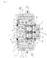
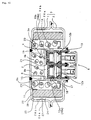
- Fig. 1 is a vertical cross sectional view of a first embodiment of a gas generator for an air bag according to the present invention, which shows a structure particularly suitable for being arranged in a driver side.
- the gas generator comprises a housing 3 which is formed by joining a diffuser shell 1 with gas discharge ports and a closure shell 2 forming a inner accommodating space with the diffuser shell, and an inner cylindrical member 4 formed in a substantially cylindrical shape arranged in the housing 3, thereby forming a first combustion chamber by an outer side of the inner cylindrical member 4. Further, a stepped notch portion 6 is provided inside the inner cylindrical member, a partition wall 7 formed in a substantially flat circular shape is arranged in the stepped notch portion, the partition wall further partitions an inner portion of the inner cylinder into two chambers so as to form a second combustion chamber 5 b in the diffuser shell side (in the upper space side) and an ignition means accommodating chamber 8 in the closure shell side (in the lower space side) , respectively.
- the first combustion chamber 5 a and the second combustion chamber 5 b are concentrically provided in the housing 3 and arranged in adjacent to each other in the radial direction of the housing.
- Gas generating agents (9a, 9b) which is to be burnt by ignition means activated on an impact so as to generate combustion gas are stored in the first and second combustion chambers, and the ignition means to be actuated on an impact is stored in the ignition means accommodating chamber 8.
- a through hole 10 is provided in the inner cylindrical member 4 which defines the first combustion chamber 5 a and the second combustion chamber 5 b, and the through hole is closed by a seal tape 11. And, the seal tape 11 is ruptured when the gas generating agent is burnt, both combustion chambers can be communicated with each other by the through hole 10.
- This seal tape 11 needs to be adjusted on its material and a thickness so that the seal tape is not broken due to the combustion of the gas generating agent 9a in the first combustion chamber 5a but is broken when the gas generating agent 9 b in the second combustion chamber 5 b is burnt.
- a stainless seal tape having a thickness of 40 ⁇ m is used.
- the through hole 10 does not function to control an internal pressure in the combustion chamber 5 b since an opening area thereof is formed larger than a gas discharge port 26 b.
- the ignition means comprises two electric ignition type igniters 12a and 12b to be activated by an activating signal outputted on a basis of detection by the sensor, and the igniters are provided in parallel to each other in one initiator collar 13 so as to exposing head portions thereof.
- two igniters are fixed to the initiator collar 13 so as to form a single member by providing two igniters 12a and 12b in one initiator collar 13, thereby facilitating an assembly to the gas generator.
- the initiator collar 13 is formed in a size capable of being inserted into the inner cylindrical member 4, the igniters are easily and securely fixed by crimpig the lower end of the inner cylindrical member 4 so as to fix the initiator collar after inserting the initiator collar 13 provided with two igniters 12a and 12b into the inner cylinder 4.
- two igniters (12a, 12b) in the initiator collar 13 a direction of each igniter can be easily controlled.
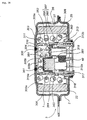
- two igniters are arranged eccentrically with respect to the center axis of the housing. In case of arranging so as to align the direction of the igniters 12a and 12b, as shown in a back view of the gas generator according to the present embodiment in Fig.
- a lead wire 50 connecting the igniters (12a and 12b) to a control unit (not shown) can be drawn out in the same direction on the same plane.
- the lead wire 50 is connected to each igniter (12a, 12b) via a connector 50a and the connectors are provided in parallel on the same plane.
- the connector By forming the connector in L-letter, the lead wire for transmitting an electric signal (an activating signal) to the igniter in a direction perpendicular in the axial direction of the housing (that is, in the radial direction of the housing), and at that time, the lead wire connected to each igniter is drawn out in the same direction.
- a substantially cylindrical separating cylinder 14 is arranged in a space between the initiator collar 13 and the partition wall 7 so as to surround one igniter 12b (hereinafter, refer to as "a second igniter") , a first transfer charge accommodating chamber 15a defined in the outer side of thereof and a second transfer charge accommodating chamber 15b are defined in the inner side thereof respectively, and the igniter and the transfer charge constituting the ignition means together with the igniters are stored in each accommodating chambers.
- transfer charges (16a, 16b) constituting the ignition means together with the igniters are securely partitioned into the respective igniters (12a, 12b) .
- a flame generated when the first igniter 12a is ignited (activated) , ignites and burns the transfer charge 16a in the accommodating chamber 15a and then, the flame thereof passes through the flame-transferring hole 17 formed in the inner cylindrical member 4 and ignites and burns a gas generating agent 9a with seven holes stored in the first combustion chamber 5a positioned in the radial direction of the chamber 15a.
- the second igniter 12b ignites and burns the second transfer charge 16b stored in the accommodating chamber 15b and the flame thereof passes through the flame-transferring hole 19 provided in the axial direction of the accommodating chamber 15b and ignites and burns a gas generating agent 9b with a single hole stored in the second combustion chamber 5b disposed on an extension thereof.
- the combustion gas generated in the second combustion chamber 9b passes through the through hole 10 provided in the diffuser shell side 1 of the inner cylindrical member 4 and flows into the first combustion chamber 5a.
- the gas generator shown in Fig. 1 in order to stabilize an actuation performance, there is a case that the second igniter 12b and the first igniter 12a are simultaneously ignited, however, the former 12b is not activated prior to the latter 12a. That is, the gas generating agent 9b stored in the second combustion chamber 5b is burnt at the same time or at a delayed timing of the combustion of the gas generating agent 9a stored in the first combustion chamber 5a.
- the seal tape 11 is not ruptured by the combustion of the first gas generating agent 9a but is ruptured only by the combustion of the second gas generating agent 9b.
- the separating cylinder 14 arranged between the initiator collar and the partition wall is, as shown in a main portion enlarged view in Fig. 3, arranged so that a hole portions 21 corresponding to an outer shape of the separating cylinder 14 are provided on the lower surface of the partition wall 7 and the upper surface of the initiator collar 13, and the upper end and the lower end of the separating cylinder 14 are fitted into the respective hole portions.
- a pressure of the gas generated by the combustion serves so as to expand the separating cylinder in the radial direction, however, by arranging the separating cylinder as shown in Fig. 3, the upper and lower end portions of the separating cylinder are securely supported to peripheral walls of the hole portions where the respective portions are fitted, so that, in comparison with the case of simply interposing the separating cylinder between the partition wall and the initiator collar, leaking of the combustion gas and the flame of the transfer charge can be prevented securely.
- a common coolant/filter 22 for purifying and cooling the combustion gas generated by the combustion of the gas generating agents (9a, 9b) is disposed in the housing 3, an inner peripheral surface in the diffuser shell 1 side thereof is covered with a short pass preventing member 23 so that the combustion gas does not pass between an end surface of the coolant/filter 22 and a ceiling portion inner surface 28 of the diffuser shell 1.
- An outer layer 24 for preventing the filter 22 from expanding outwardly due to passing of the combustion gas or the like is arranged on the outer side the coolant/filter 22.
- the outer layer 24 is, for example, formed by using a layered wire mesh body, and in addition, may be formed by using a porous cylindrical member having a plurality of through holes on a peripheral wall surface or a belt-like suppressing layer obtained by forming a belt-like member with a predetermined width into an annular shape.
- a gap 25 is further formed on the outer side of the outer layer 24 so that the combustion gas can pass through the entire surface of the filter 22.
- a gas discharge port 26 formed in the diffuser shell is closed by a seal tape 27 so as to stop entering an ambient air.
- the seal tape 27 is ruptured at a time of discharging the gas.
- the seal tape 27 aims to protect the gas generating agent from a moisture in the outer portion, and does not have any influence on controlling the performances such as the combustion internal pressure.
- the transfer charge 16a stored in the first transfer charge accommodating chamber 15a is ignited and burnt, and the flame thereof passes through the flame-transferring hole 17 in the inner cylindrical member 4 and burns the porous cylindrical first gas generating agent 9a with seven holes and stored in the first combustion chamber 5a.
- the transfer charge 16b stored in the second transfer charge accommodating chamber 15b is ignited and burnt, and the flame thereof ignites and burns the single-hole cylindrical second gas generating agent 9b stored in the second combustion chamber 5b.
- the ignition timings of two igniters 12a and 12b are adjusted. That is, an output's forms (an actuation performance) of the gas generator can be optionally adjusted by activating the second igniter after the activation of the first igniter or simultaneously activating the first igniter and the second igniter.
- the respective combustion chambers (5a, 5b) adopt the gas generating agents (9a, 9b) to provide different shapes from each other, respectively, and the porous cylindrical first gas generating agent 9a and the single-hole cylindrical second gas generating agent 9b are respectively stored in the first combustion chamber 5a and the second combustion chamber 5b.
- the amount of the gas generating agent stored in each combustion chamber (5a, 5b) is different, and the gas generating agents (9a, 9b) at an amount of 35 g and 6 g are stored respectively in the first combustion chamber 5a and the second combustion chamber 5b. Consequently, in this gas generator, the output's forms can be adjusted more precisely. Naturally, a shape, a composition, a composition ratio, an amount, etc. of the gas generating agent may be changed to obtain the desired output's forms.
- the actuation performance of the gas generator mentioned above can be also confirmed, for example, according to a tank combustion test mentioned below.
- a gas generator for the air bag is fixed in a SUS (stainless steel) tank with an inner volume of 60 litter and is connected to an outer ignition electric circuit after sealing the tank at a room temperature.
- a pressure increase change inside the tank is measured by a pressure transducer independently placed in the tank for a time between 0 and 200 milliseconds.
- Each of the measured data is finally set to a tank pressure/time curve by a computer process, and a curve estimating a performance of a gas generating molded article (hereinafter, refer to as "a tank curve") is obtained.
- a tank curve a curve estimating a performance of a gas generating molded article
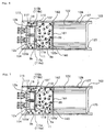
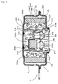
- Fig. 4 is a vertical cross sectional view which shows a second embodiment of a gas generator for an air bag according to the present invention.
- the gas generator shown in this drawing is also structured to be particularly suitable for being arranged in a driver side as same as the gas generator shown in Fig.1.
- the gas generator shown in this drawing is different from the gas generator shown in Fig. 1, in a way that a flow passage forming member 51 is arranged in the first combustion chamber 5a, and a flow passage 52 through which the combustion gas generated in the second combustion chamber 5b passes is formed between the flow passage forming member 51 and the ceiling portion inner surface 28 of the diffuser shell.
- the flow passage forming member 51 is formed into an annular shape obtained by bending an inner periphery and an outer periphery of a circular member so as to form an inner peripheral wall 53 and an outer peripheral wall 54, and a supporting wall 56 for forming a space with the ceiling portion inner surface 28 of the diffuser shell is integrally formed on a circular portion 55 connecting the both peripheral wall surfaces. Then, the flow passage forming member 51 holds the inner cylindrical member 4 with the inner peripheral wall 53 thereof and brings a supporting wall 56 in contact with the ceiling portion inner surface 28 of the diffuser shell, by whereby a fixed space is obtained between the circular portion 55 and the ceiling portion inner surface 28 of the diffuser shell. And since multiple through holes 57 are formed on the supporting wall, the space can function as a gas flow passage 52.
- the gas flow passage 52 is communicated with the second combustion chamber 5b by the through hole 10 of the inner cylindrical member 4 due to the combustion of the gas generating agent 9b in the second combustion chamber 5b. Therefore, the combustion gas generated in the second combustion chamber 5b is discharged to the gas flow passage 52 from the through hole 10, passes through the coolant/filter 22 and is discharged from the gas discharge port 26.
- the first combustion chamber 5a and the second combustion chamber 5b can be communicated with each other via the net space of the coolant/filter 22, however, the combustion gas generated by the combustion of the gas generating agent stored in either combustion chamber passes through the coolant/filter 22 and is discharged from the gas discharge port 26 as it is. Consequently, a flame generated by the gas generating agent which is firstly ignited and burnt does not ignite the gas generating agent stored in the other combustion chamber.
- the single-hole gas generating agent 9a' stored in the first combustion chamber 5a is ignited and burnt only by the activation of the first igniter 12a, and the gas generating agent 9b in the second combustion chamber 5b is ignited and burnt only by the activation of the second igniter 12b.
- the flame of the gas generating agent ignited by the firstly activated igniter does not burn the gas generating agent in the other combustion chamber, and thereby a stable tank curve can be obtained in the tank combustion test.
- the combustion gas generated in the first combustion chamber 5a passes through the through hole 10 of the inner cylindrical member 4 so as to ignite and burn the gas generating agent 9b in the second combustion chamber 5b.
- the combustion gas generated in the first combustion chamber 5a passes through the coolant/filter 22 and is discharged as it is without igniting the gas generating agent 9b in the second combustion chamber 5b.
- the gas generating agent 9b stored in the second combustion chamber 5a can be optionally ignited and burnt only by activating the second igniter 12a.
- the through hole 10 is not closed by the seal tape. But even in the case that the hole 10 is closed by the seal tape, the gas generating agent can be further independently ignited and burnt in each combustion chamber. Accordingly, it is possible to make an output performance of the gas generator most suitable in accordance with a circumstance at a time of collision of the vehicle.
- the transfer charge 16b to be ignited by the second igniter 12b is arranged in the second combustion chamber 5b, but not in the separating cylinder 14.
- the transfer charge 16b By arranging the transfer charge 16b in this manner, the flame can uniformly burn the gas generating agent 9b in the second combustion chamber 5b when the transfer charge 16b is ignited and burnt by the activation of the second igniter 12b. And further, the transfer charge 16b cannot be directly burnt by the flame of the transfer charge 16a in the first transfer charge accommodating chamber 15a.
- the same reference numerals are attached thereto and a description thereof will be omitted.
- the gas generating agents having different shapes are charged in the respective combustion chambers at different amounts.
- the gas generating agent 9a in the first combustion chamber 5a has a surface area at a unit weight of a gas generating agent smaller than that of the gas generating agent 9b in the second combustion chamber 5b, and a proportions of the charging amount between the gas generating agents, i.e. a rate of the first gas generating agent to the second gas generating agent is 35/6.
- a ignition means a tank curve obtained when only the gas generating agent 9a in the first combustion chamber 5a is burnt by the activation of the first igniter 12a of the gas generator shown in Fig. 4. This tank curve moves upward , drawing a gentle curve. This is because the gas generating agent 9a in the first combustion chamber 5a has a surface area at a unit weight of the gas generating agent smaller than that of the gas generating agent 9b in the second combustion chamber 5b, and does not burn at a time after ignition.
- a + B (simultaneous) ignition means a tank curve obtained when the first and second igniters (12a, 12b) are simultaneously activated so as to simultaneously burn the gas generating agents (9a, 9b) in the first and second combustion chambers 5a and 5b.
- the tank pressure rapidly increases simultaneously when the activating signal is transmitted to both igniters (12a, 12b) .
- the second gas generating agent 9b in the second combustion chamber 5b having a larger surface area per a unit weight burns at a time at the same time of the ignition so as to discharge the combustion gas.
- the combustion gas generated by the gas generating agent 9a in the first combustion chamber 5a is continuously generated, so that the increased output curve (the tank curve) is maintained for a while.
- a + B (T milliseconds delayed) ignition means a tank curve obtained when the second igniter 12b is activated to burn the gas generating agent 9b in the second combustion chamber 5b at T milliseconds after the first igniter 12a to burn the first gas generating agent 9a in the first combustion chamber 5a is firstly activated.
- This tank curve is substantially the same as the tank curve of "A ignition” before T milliseconds, however, after the second igniter 12b is activated (i.e. after T milliseconds), the tank curve goes upward at a time. This is because an amount of the gas rapidly generated by the combustion of the gas generating agent 9b in the second combustion chamber 5b is added.
- the maximum output (X kPa) thereof is more than the maximum output (Y kPa) of the tank curve of "A + B (simultaneous) ignition".
- the gas generating agents (9a, 9b) in both the combustion chambers (5a, 5b) are burnt at a time in the case of "A + B (simultaneous) ignition", however, on the other hand, the second gas generating agent 9b in the second combustion chamber 5b is ignited and burnt at a T milliseconds after the first gas generating agent 9b charged in the first combustion chamber 5a, so that the generated heat is continuously maintained at that degree.
- the second igniter 12b is activated at an interval of T milliseconds after the first igniter 12a is activated.
- the delay timing can be set to an optional interval by adjusting the ignition circuit.
- a judging circuit judges a speed at a time of the collision of the vehicle or an attitude of an occupant (for example, a person with a sitting height is long or short or a person with an attitude of holding to the steering wheel) , or the like at a moment so as to set a suitable delay time and actuate the ignition means, by whereby it is possible to inflate the air bag in an optimum inflating mode under various circumstances.
- Fig. 6 is a vertical cross sectional view which shows the other embodiment of a gas generator for an air bag according to the present invention.
- This gas generator is structured such as to be particularly suitable for being arranged in passenger sides.
- the gas generator shown in this drawing has in the housing 103 formed into a cylindrical shape having an axial core length longer than an outermost diameter and having a plurality of gas discharge ports on a peripheral wall thereof, and an ignition means to be actuated on an impact, gas generating agents (9a, 9b) which is to be ignited and burnt by the ignition means and generate a combustion gas for inflating the air bag and a coolant/filter 122 for cooling and/or purifying the combustion gas generated by the combustion of the gas generating agents.
- two combustion chambers (105a, 105b) provided in the housing 103 are formed into a cylindrical combustion chamber 105a and an annular combustion chamber 105b respectively, and concentrically provided so as to be adjacent to each other to an axial direction of the housing 103, and a communicating hole 110 which allows communication between the combustion chambers 105a and 105b is provided.
- the gas generator shown in the present embodiment is formed in a long shape in the axial direction since the housing is formed in a long cylindrical shape in the axial direction.
- the gas generator formed in this shape can be a gas generator having a simple structure and easily manufactured while the output of the gas generator and the timing for increasing the output can be optionally adjusted by arranging two combustion chambers 105a and 105b to be in a combination of the cylindrical combustion chamber 105a and the annular combustion chamber 105b as mentioned above, concentrically providing them so as to be adjacent to each other and making both the combustion chambers communicate with each other.
- the ignition means comprises two or more igniters to be activated on an impact and the respective igniters (12a, 12b) are provided in one initiator collar 113 so as to be parallel to each other, and thereby an assembly thereof can be easily performed. Further, the igniters (12a, 12b) fixed in one initiator collar 113 and stored in the housing is arranged eccentrically with respect to an axis of the housing .
- a coolant/filter 122 formed in a substantially cylindrical shape is arranged in the housing 103 so as to oppose to a housing inner peripheral surface on which a plurality of gas discharge ports 126 are formed, and a predetermined gap 125 is obtained between the filter 122 and the housing inner periphery.
- the first combustion chamber 105a is defined so as to be adjacent to a space in which the coolant/filter 122 is installed, and the ignition means including two igniters (12a, 12b) is concentrically arranged so as to be adjacent to the first combustion chamber 105a.
- the annular second combustion chamber 105b is defined in the radial direction of the ignition means, the first combustion chamber 105a and the second combustion chamber 105b are provided so as to be adjacent to each other in the axial direction of the housing 103.
- the different gas generating agents (9a, 9b) are respectively charged in the first and second combustion chambers, and in the gas generator shown in this drawing, the porous cylindrical first gas generating agent 9a and the single-hole cylindrical second gas generating agent 9b are respectively stored in the first combustion chamber 105a and the second combustion chamber 105b.
- the above ignition means comprises the transfer charges which are to be ignited and burnt according to the activation of the igniters (12a, 12b) and ignites the gas generating agents (105a, 105b) by the flame thereof, and the transfer charges are partitioned for each igniter and independently ignited and burnt at each of the igniters.
- a space where the transfer charge partitioned for each igniter is stored is defined by a cylindrical member, a first transfer charge accommodating chamber 115a where a first transfer charge 116a is stored communicates with the first combustion chamber 105a by a flame-transferring hole 119 on a partition wall 107 arranged between the ignition means and the first combustion chamber 105a, and a second transfer charge accommodating chamber 115b where a second transfer charge 116b is stored communicates with the second combustion chamber 105b by a flame-transferring hole 117 formed on the cylinder member 104 which defines the accommodating chamber 115b. Then, the first combustion chamber 105a and the second combustion chamber can be communicates with each other by the through hole 110 when the seal tape 11 is ruptured due to the combustion of the gas generating agent 9b.
- the transfer charge 116a in the first transfer charge accommodating chamber 115a is ignited and burnt, and the flame thereof passes through the flame-transferring hole 119 in the partition wall member 107 and ignites and burns the gas generating agent 9a stored in the first combustion chamber 105a so as to generate the combustion gas.
- This combustion gas is purified and cooled while passing through the coolant/filter 122 and is discharged from a gas discharge port 126.
- the transfer charge 116b in the second transfer charge accommodating chamber 115b is ignited and burnt, and the flame thereof ignites and burns the gas generating agent 9b in the second combustion chamber 105b.
- the combustion gas generated in the second combustion chamber 105b passes in the first combustion chamber 105a through the through hole 110 in the partition wall 107, is purified and cooled while passing through the coolant/filter 122 and then, is discharged from the gas discharge port 126.
- the combustion gas generated by the combustion of the first gas generating agent and the combustion gas generated by the combustion of the second combustion gas are both purified and cooled while passing through the same coolant/filter 122.
- the gas discharge port 126 is closed by a seal tape 127.
- This seal tape 127 aims to protect the gas generating agent from a moisture outside, is ruptured by the combustion gas generated due to the combustion of the gas generating agent so as to discharge the combustion gas. Accordingly, the seal tape 127 does not control the combustion performance (the combustion internal pressure) of the gas generating agent.
- the flame-transferring hole 119 and the flame-transferring hole 117 are respectively closed by the seal tape 20 and the seal tape 18.
- a communicating hole 161 communicating both chambers is provided in a sectioning member 160 which partitions the first combustion chamber 105b and the space where the coolant/filter 122 is installed, the combustion gas generated in the first and second combustion chambers (105a, 105b) reaches the space installing the coolant/filter 122 through the communicating hole 161.
- a communicating hole 161 having substantially the same size as an inner diameter of the coolant/filter 122 is formed in the sectioning member 160.
- a wire mesh 162 is placed in the communicating hole 161 so that the gas generating agent 9a in the first combustion chamber 105a does not move to a side of the space where the coolant/filter 122 is installed, at a time of the combustion. Any kinds of wire mesh can be used for this wire mesh 162 as long as it does not have a mesh size which can prevent the first gas generating agent 9a from moving during the combustion and does not have a draft resistance such as to control the combustion performance.
- the gas generating agents (9a, 9b) stored in the respective combustion chambers (105a, 105b) are independently ignited and burnt by adjusting the activation timing of two igniters (12a, 12b) , so that the output's forms (the actuation performance) of the gas generator can be optionally adjusted. Consequently, in various circumstances such as the speed of the vehicle at a time of collision, an environmental temperature, it is possible to make it most suitable to inflate the air bag in the case of using an air bag apparatus mentioned below.
- two combustion chambers provided in the housing can be provided so as to be adjacent to each other in the axial direction and the radial direction of the housing, further as shown in Fig. 7.
- a second combustion chamber 105b' is extended in the axial direction of the housing by bending the partition wall 107' which defines a first combustion chamber 105a' and ignition means and a second combustion chamber 105b' in the axial direction, thereafter forming a end thereof into a flange shape and placing it in contact with an inner periphery of the housing.
- the second combustion chamber is extended in the axial direction, that is, extended to the first combustion chamber side, by whereby the first combustion chamber and the second combustion chamber are adjacent to each other in the axial direction and the radial direction of the housing.
- a peripheral wall is provided with the partition wall 107'' so that a flange shaped end of the partition wall extends to be in contact with the sectioning member 160, on as shown in Fig. 8
- a first combustion chamber 105a'' and a second combustion chamber 105'' are adjacent to each other in the radial direction of the housing and concentrically provided. Consequently, a volume of the second combustion chamber can be increased at a degree not less than that of the gas generator shown in Fig. 7.
- the gas generators shown in Figs. 7 and 8 can increase the volume of the second combustion chamber, they are convenient in the case of using a lot of second gas generating agent. Further, also in the gas generators shown in Figs. 7 and 8, in the same manner as the above gas generator shown in Fig. 6 , there can be obtained a gas generator for an air bag which can optionally adjust the output's forms (the actuation performance) of the gas generator while it has a simple structure and is further small. In the gas generators shown in Figs. 7 and 8, the same reference numerals are attached to the same elements in Fig. 6, and a description thereof will be omitted.
- Fig. 9 is a vertical cross sectional view which shows further another embodiment of a gas generator for an air bag according to the present invention.
- the gas generator shown in this drawing is structured such as to be particularly suitable for being arranged in a driver side in the same manner as that of the gas generator shown in Figs. 1 and 4.
- a first combustion chamber 305a and a second combustion chamber 305b are partitioned by an inner cylindrical member 304 and provided in the housing 3 so as to be concentrically adjacent to each other.
- a stepped notch portion 306 is provided on an inner peripheral surface of the inner cylindrical member 304 at a predetermined height, and a partition wall 307 which defines the second combustion chamber 305b and an ignition means accommodating chamber 308 is arranged in the stepped notch portion 306.
- the partition wall 307 is, as shown in an exploded perspective view in Fig. 10, constituted by a sectioning circular member 350 engaged with the stepped notch portion 306 of the inner cylindrical member 304 and a seal cup member 360 engaged with the sectioning circular member 350.
- the sectioning circular member 350 is formed in a substantially flat circular shape, and has an opening portion 351 inwardly fitting a transfer charge accommodating portion 361 of a seal cup member 360 mentioned below, a circular hole portion 352 obtained by scraping out a bottom surface in a circular shape and storing an upper portion of an igniter 312b, and a second flame-transferring hole 319 extending and pierced through a substantially center of the circular hole portion.
- the seal cup member 360 has a cylindrical transfer charge accommodating portion 361 fitted into the opening portion 351 of the sectioning circular member 350 and protruding into the second combustion chamber 305b, and a cylindrical igniter receiving port 362 formed at a position opposing to the circular hole portion 352 of the sectioning circular member 350 and extending to a side opposite to the transfer charge accommodating portion 361.
- a first transfer charge 316a is stored inside the transfer charge accommodating portion 361, and a second igniter 312b is inwardly fitted to the igniter receiving port 362.
- the sectioning circular member 350 and the seal cup member 360 are engaged with each other by fitting the transfer charge accommodating portion 361 of the seal cup member 360 into the opening portion 351 of the sectioning circular member 350, and an upper portion of the second igniter 312b inwardly fitted to the igniter receiving port 362 exposes into the circular hole portion 352 of the sectioning circular member 350.
- the partition wall 307 constituted by the sectioning circular member 350 and the seal cup member 360 is, as shown in Fig. 9, engaged with the stepped notch portion 306 formed on the inner peripheral surface of the inner cylindrical member 304. That is, the peripheral edge of the sectioning circular member 350 is supported to the stepped notch portion 306, and the seal cup member 360 is supported in contact with the sectioning circular member 350. Further, the peripheral edge of the seal cup member 360 is formed by being bent in the same direction as that of the igniter receiving port 362, and a bent portion 363 is fitted into a groove 364 provided on the inner peripheral surface of the inner cylindrical member 304. Accordingly, the sectioning circular member 350 is supported by the seal cup member 360 and is prevented from moving in the axial direction of the housing 3.
- the partition wall 307 i.e. the seal cup member 360
- the inner cylindrical member 304 are engaged with each other with no gap by fitting the bent portion 363 in the peripheral edge of the seal cup member 360 into the groove 364 on the inner peripheral surface of the inner cylindrical member 304. Accordingly, in the inner cylindrical member 304, the ignition means accommodating chamber 308 provided in the closure shell side 2 and the second combustion chamber 305b provided in the diffuser shell side 1 are securely partitioned by an ignition means sealing structure comprising a combination of the seal cup member 360 and the groove 364.
- the igniter receiving port 362 formed in the seal cup member 360 is structured such that a skirt portion thereof spreads like a fan, and an O-ring 381 is arranged in an inner side thereof, that is, between this and the second igniter 312b stored in the storing port 362, and sealing between the receiving port 362 and the second igniter 312b is performed. And since the O-ring 381 is also press-contacted to an igniter fixing member 382 mentioned below, the second igniter 312b is arranged in a space defined by the circular hole portion 352 of the sectioning circular member, the igniter receiving port 362 of the seal cup member, the O-ring 381 and the igniter fixing member 382.
- an igniter seal structure comprising the skirt portion of the igniter receiving port 362, the O-ring 381 and the igniter fixing member 382 (hereinafter, referred as "an igniter seal structure"). Accordingly, the flame generated by the activation of any igniter does not directly flow into the space where the other igniter is stored.
- two igniters 312a and 312b are fixed to a single initiator collar 313 in order to secure an easiness for arranging in the housing.
- two igniters 312a and 312b are supported by the igniter fixing member 382 engaged with the initiator collar 313, and are fixed to the initiator collar 313.
- the igniter fixing member 382 is formed in a shape which covers an upper surface of the initiator collar 313, and has a hole portion 384 passing through the upper portion of each igniter and supporting a shoulder portion 383.
- Two igniters 312a and 312b arranged in the initiator collar 313 are fixed to the igniter fixing member 382 outwardly fitted to the initiator collar 313.
- two igniters 312a and 312b can be easily assembled to the initiator collar 313.
- the first igniter 312a and the second igniter 312b are formed in different sizes, and the outputs thereof are different, however, the igniters having the same output may be used.
- the flame generated due to the activation of the first igniter 312a ignites and burns the first transfer charge 316a arranged above.
- the flame generated by the combustion of the first transfer charge 316a neither flows into the space where the second igniter 312b is stored, due to the igniter seal structure, nor flows into the second combustion chamber 305b due to the ignition means seal structure constituted by the bent portion 363 of the seal cup member 360 and the groove 364 of the inner cylindrical member 304.
- the flame generated by the combustion of the first transfer charge 316a exclusively flows into the first combustion chamber 305a through the first flame-transferring hole 317 formed on the peripheral wall of the inner cylindrical member 304, and ignites and burns a first gas generating agent 309a so as to generate the combustion gas.
- the flame generated by the activation of the second igniter 312b exclusively flows into the second combustion chamber 305b through the second flame-transferring hole 319 formed on the circular hole portion 352 of the sectioning circular member 350, and ignites and burns a second gas generating agent 309b so as to generate the combustion gas.
- the second transfer charge is not arranged and the second gas generating agent 309a is directly ignited and burnt by the flame generated by the activation of the second igniter 312b.
- the combustion gas generated by the combustion of the first gas generating agent 309a and the second gas generating agent 309b is thereafter purified and cooled while passing through the common coolant/filter 22, passes through the gap 25 and is discharged from the gas discharge port 26.
- the seal tapes 318 and 320 for closing the first and second flame-transferring holes are ruptured when the flame of the igniter and the combustion gas of the transfer charge pass therethrough, and the seal tape 27 for closing the gas discharge port 26 is ruptured when the combustion gas passes therethrough
- positioning means is formed in a portion where the igniters 312a and 312b are arranged, so that a lead wire 15' connected to each igniter is specified.
- This kind of positioning means can be achieved by using a different types of connector 16' at each igniter, for example, as shown in a main portion exploded perspective view in Figs. 11a to 11d. In the positioning means shown in Fig.
- the structure is made such that a positioning groove (or projection) 17' is formed in a connector and a forming position of a projection (or groove) 18' corresponding to the positioning groove (or projection) 17' is different at each igniter.
- a position of the groove (or projection) 17' of each connector is changed so that the connector can not be mounted regularly being interfered with each other if the connector 16' is not mounted in a normal direction when mounting the connector 16' to the gas generator.
- a positioning groove (or projection) 19' is provided only in one connector 21'.
- a connector 21A' provided with the groove (or projection) 19' can be engaged with an igniter 22' in a side that a projection (or groove) 20' is not provided, however, a connector 21B' provided with no groove (or projection) 19' can not be engaged with an igniter 22a' in a side that the projection (or groove) 20' is provided.
- an error on connecting the connector 21' can be easily found at a time of assembling.
- Fig. 11c a shape of a connecting and engaging portion 23' in each connector is different from each other.
- two connectors are joined to one and a positioning groove (or projection) 24' is further formed. As this positioning means, in addition, it is possible to suitably use means for preventing the connectors from being erroneously connected.
- the first gas generating agent 309a and the second gas generating agent 309b are independently ignited and burnt due to the activation of the first igniter 312a and the second igniter 312b, respectively, however, there is a case that only the first igniter 312a is energized so as to be ignited, thereby igniting and burning only the gas generating agent 309a in the first combustion chamber 305a. Namely, this corresponds to a case that the second gas generating agent 309b and the second igniter 312b are not burnt but remained.
- the gas generating agent 309b in the second combustion chamber 305b at a further more delayed timing (for example, 100 milliseconds or more, or the like) in comparison with a normal delayed ignition timing (for example, 10 to 40 milliseconds, or the like) for activating the second igniter 312b, after the actuation of the gas generator (only the first igniter 312a) .
- a normal delayed ignition timing for example, 10 to 40 milliseconds, or the like
- an automatic igniting material 385 which is to be ignited and burnt due to a transmission of a combustion heat of the first gas generating agent 309a can be provided in the second combustion chamber 305b.
- the ignition of the second gas generating agent 309b by the automatic igniting material 385 is performed after a sufficient time more than the normal predetermined delayed time in the case of activating the second igniter 312b has passed (i.e. an interval between activation of each igniter) after the activation of the first igniter 312a. That is, this is different from the matter of delaying the combustion of the second gas generating agent 309b (i.e. delaying the activation of the second igniter 312b) for the purpose of adjusting the actuation performance of the gas generator.
- the second gas generating agent 309b is not ignited and burnt by the automatic igniting agent 385 while optionally delaying the activation current to the second igniter 312b to adjust the actuation performance of the gas generator.
- the automatic igniting material 385 may be arranged in combination with the second igniter.
- the first combustion chamber 305a and the second combustion chamber 305b are defined by the inner cylindrical member 304.
- a through hole 310 is provided in this inner cylindrical member 304, and the through hole 310 is closed by a stainless plate 311.
- the stainless plate 311 is bonded to the inner cylindrical member 304 by an adhesive member such as an adhesive material, opens the through hole 310 exclusively by the combustion of the second gas generating agent 309b, but does not open by the combustion of the first gas generating agent 309a.
- the through hole 310 is closed by the stainless plate 311 in this manner because the flame of the first gas generating agent 309a is prevented from flowing into the second combustion chamber 305b through the through hole 310 so as to burn the second gas generating agent 309b.
- the above can be realized by welding, bonding or heat-sealing a rupturing plate which is to be broken, peeled, burnt out or taken out due to a pressure generated by the combustion of the second gas generating agent, to the inner cylindrical member so as to close the through hole 310, or by providing a notch on a peripheral wall of the inner cylindrical member 304, or by forming the peripheral wall of the inner cylindrical member 304 so as to partly have a thin thickness.
- a shielding plate 386 formed in a substantially ring shape may be arranged so as to cover the through hole 310 provided in the inner cylindrical member 304.
- the seal tape closing the through hole 310 is protected by the shielding plate 386 even when the combustion gas is generated by the combustion of the first gas generating agent 309a, and therefore, the seal tape is not broken by the combustion of the first gas generating agent 309a.
- the through hole 310 of the inner cylindrical member 304 is exclusively opened only by the combustion of the second gas generating agent 309b but is not opened by the combustion of the first gas generating agent 309a.
- the combustion gas firstly generated in the first combustion chamber 305a does not flow into the second combustion chamber 305b and the gas generating agent 309b in the second combustion chamber 305b is ignited and burnt by the activation of the second igniter 312b (in some cases, the combustion of the automatic igniting material 385) .
- the combustion gas generated by the combustion of the second gas generating agent 312b passes inside the first combustion chamber 305a through the through hole 310 opened by the combustion thereof, and thereafter is purified and cooled by the coolant/filter 22 so as to be discharged from the gas discharge port 26.
- the same reference numerals are attached to the same elements as those of Fig. 1 and a description thereof will be omitted.
- Fig. 14 shows an embodiment of an air bag apparatus according to the present invention which comprises the electric ignition type ignition means.
- the air bag apparatus comprises a gas generator 200, an impact sensor 201, a control unit 202, a module case 203 and an air bag 204.
- the gas generator 200 the gas generator described with reference to Fig. 1 is used and the actuation performance thereof is adjusted so as to apply as a small impact as possible to the occupant at the initial stage of the actuation of the gas generator.
- the impact sensor 201 can be, for example, constituted by a semiconductor type acceleration sensor.
- This semiconductor type acceleration sensor is structured such that four semiconductor strain gauges are formed on a silicone base plate which is to be bent when the acceleration is applied, and these semiconductor strain gauges are bridge-connected. When the acceleration is applied, the beam defects and a strain is produced on the surface. Due to the strain, a resistance of the semiconductor strain gauge is changed, and the resistance change is detected as a voltage signal in proportion to the acceleration.
- the control unit 202 is provided with an ignition decision circuit, and the signals from the semiconductor type acceleration sensor is inputted to the ignition decision circuit.
- the control unit 202 starts calculation at a time when the impact signal from the sensor 201 exceeds a certain value, and when the calculated result exceeds a certain value, it outputs an activating signal to the igniter 12 of the gas generator 200.
- the control unit 202 and the igniter 12 of the gas generator 200 are connected by a lead wire taken out in the same direction on the same plane via the connector connected to the igniter 12.
- the module case 203 is formed, for example, by a polyurethane, and includes a module cover 205.
- the air bag 204 and the gas generator 200 are stored in the module case 203 so as to be constituted as a pad module.
- This pad module is generally mounted to a steering wheel 207 in the case of being mounted to a driver side of an automobiles.
- the air bag 204 is formed by a nylon (for example, a nylon 66), a polyester or the like, and a bag port 206 thereof surrounds the gas discharge port of the gas generator and is fixed to a flange portion of the gas generator in a folded state.
- a nylon for example, a nylon 66
- a polyester for example, a polyester
- a bag port 206 thereof surrounds the gas discharge port of the gas generator and is fixed to a flange portion of the gas generator in a folded state.
- the semiconductor type acceleration sensor 201 detects the impact at a time of collision of the automobiles, the signal is transmitted to the control unit 202, and the control unit 202 starts calculation at a time when the impact signal from the sensor exceeds a certain value.
- the calculated result exceeds a certain value, it outputs the activating signal to the igniter 12 of the gas generator 200.
- the igniter 12 is activated so as to ignite the gas generating agent, and the gas generating agent burns and generates the gas.
- the gas is discharged into the air bag 204, by whereby the air bag breaks the module cover 205 so as to inflate, thereby forming a cushion for absorbing an impact between the steering wheel 207 and the occupant.
- a gas generator including two or more combustion chambers, a gas generator including two igniters, a gas generator including two different gas generating means, a gas generator including an igniter having a lead wire, a gas generator having a combustion chamber and ignition means in an inner cylindrical member and a gas generator including an automatic igniting material.
- the porous cylindrical first gas generating agent 9a having seven holes may be stored in the first combustion chamber 5a and the single-hole cylindrical second gas generating agent 9b may be stored in the second combustion chamber 5b.
- the single-hole cylindrical gas generating agent for example, the agent having an inner diameter of 0.5 to 1.5 mm, preferably 0.8 mm, an outer diameter of 2 to 3 mm, preferably 2.4 mm and a length of 2 to 6 mm, preferably 4 mm is used
- the seven-hole cylindrical gas generating agent for example, the agent having an inner diameter of 0.6 to 0.7 mm, an outer diameter of 5 to 5.3 mm and a length of 5 mm is used.
- a thickness thereof is specified by a method shown in Fig. 22.
- a center of one hole among the through holes is arranged at a center of the circle of the formed body, and the other six holes are arranged in the periphery of a central hole.
- distances (b) between the centers of respective two holes arranged in the periphery, and distances (c) between the center of these two holes and an outer end of the formed body are respectively equal to each other, and further, distances (a) between the center of the central hole and the center of each holes arranged in the periphery are respectively equal to each other.
- a regular triangle comprising (a), (b) and (a) and a regular triangle comprising (b) , (c) and (c) become substantially the same as each other.
- Six regular triangles are arranged from one central hole, and a center of the peripheral six holes is arranged at an apex of the regular triangle. That is, in the gas generating agent mentioned above, the distance of (a) (b) and (a) corresponds to the thickness of the gas generating agent, more preferably, it is preferable that these thickness (i.e. (a) (b) and (a)) are equal to each other.
- the central hole can be surrounded by peripheral eighteen holes.
- the number of holes and the arranging structure can be made advantageous in the same manner as mentioned above.
- the number of the holes, and the arranging structure can be determined according to a cooperation between an easiness for producing the gas generating agent, a producing cost and a performance, and is not particularly limited.
- the different types of gas generating agents are used in the first combustion chamber and the second combustion chamber.
- the generating pattern of the combustion gas can be changed even after the gas generating agent stored in each of the chambers starts combustion, so that a inflating pattern of the air bag can be optionally adjusted.
- Fig. 9 the different types of gas generating agents are used in two combustion chambers partitioned and formed in the housing, in the same manner as the embodiment 1. Consequently, even after the gas generating agent stored in each chamber starts burning, the generating pattern of the combustion gas can be changed and therefore, a inflating pattern of the air bag can be optionally adjusted.
- Fig. 15 shows another embodiment and is a vertical cross sectional view showing another embodiment of a gas generator for an air bag according to the present invention.
- the gas generator for the air bag shown in this drawing is characterized by a combination of a gas discharge port formed in the housing and sealing means such as a seal tape for closing this, in the gas generator shown in the embodiment 1.
- the gas generator has, in a housing 3 formed by joining a diffuser shell 1 with a gas discharge port and closure shell 2 which forms an inner storing space together with the diffuser shell, an inner cylindrical member 4 in a substantially cylindrical shape so as to define a first combustion chamber on the outer side thereof. Further, a stepped notch portion is provided inside the inner cylindrical member, a partition wall in a substantially flat circular shape is arranged in the stepped notch portion, the partition wall further divides an inner portion of the inner cylinder into two chambers so as to form a second combustion chamber and an ignition means accommodating chamber 8 in the diffuser shell side and in the closure shell side, respectively.
- the first combustion chamber 5a and the second combustion chamber 5b are concentrically provided in the housing 3 and arranged in adjacent to each other in the radial direction of the housing.
- Gas generating agents (9a, 9b) which is to be burnt by ignition means activated on an impact so as to generate combustion gas are stored in the first and second combustion chambers, and the ignition means to be activated on an impact is stored in the ignition means accommodating chamber 8.
- the different types of gas generating agents are used in the first combustion chamber and the second combustion chamber, so that the inflating pattern of the air bag can be made most suitable.
- a through hole 10 is provided in the inner cylindrical member 4 which defines the first combustion chamber 5a and the second combustion chamber 5b, and the through hole is closed by a seal tape 11. Since the seal tape 11 is ruptured when the gas generating agent is burnt, both combustion chambers can communicate with each other by the through hole 10. A material and a thickness of the seal tape 11 need to be adjusted so that the seal tape is ruptured only when the gas generating agent 9b in the second combustion chamber 5b is burnt. In the present embodiment, a stainless seal tape having a thickness of 40 ⁇ m is used. Further, the through hole 10 does not have a function of controlling an internal pressure in the combustion chamber 5b since an opening area thereof is made larger than a gas discharge port 26b.
- the ignition means comprises two electric ignition type igniters (12a, 12b) to be activated by an activating signal output on the basis of detection by the sensor, and the igniters are provided in parallel to each other in one initiator collar 13 so as to exposing head portions thereof.
- two igniters become a single member being fixed to the initiator collar 13 by providing two igniters 12a and 12b in one initiator collar 13, and thereby can be mounted to the gas generator easily.
- the initiator collar 13 is set to a size capable of being inserted into the inner cylindrical member 4.
- the igniter can be easily and securely fixed by crimping a lower end of the inner cylindrical member 4 so as to fix the initiator collar after inserting the initiator collar 13 provided with two igniters (12a, 12b) into the inner cylinder 4. And when arranging two igniters 12a and 12b in the initiator collar 13, a direction of each igniter can be easily restricted.
- a substantially cylindrical separating cylinder 14 is arranged in a space between the initiator collar 13 and the partition wall 7 so as to surround one igniter 12b (hereinafter, refer to as "a second igniter") , a first transfer charge accommodating chamber 15a and a second transfer charge accommodating chamber 15b are respectively defined in an outer side thereof and an inner side thereof, and the igniter and the transfer charge constituting the ignition means together with the igniters are stored in the respective accommodating chambers.
- transfer charges 16a and 16b constituting the ignition means together with the igniters are securely partitioned into the respective igniters (12a, 12b) .
- a seal tape 18 closing a flame-transferring hole 17 formed in the inner cylindrical member 4 is ruptured when the transfer charge 16a stored in the first transfer charge accommodating chamber 15a is burnt, by whereby the first transfer charge accommodating chamber 15a communicates with the first combustion chamber 5a.
- a seal tape 20 closing a flame-transferring hole 19 formed in the partition wall 7 is ruptured when the transfer charge 16b stored in the second transfer charge accommodating chamber 15b is burnt, by whereby the second transfer charge accommodating chamber 15b communicates with the second combustion chamber 5b.
- the gas generator is actuated such that a flame, when the first igniter 12a is ignited (activated) , ignites and burns the transfer charge 16a stored in the accommodating chamber 15a and the flame passes through the flame-transferring hole 17 formed in the inner cylindrical member 4, and ignites and burns a gas generating agent 9a with seven holes stored in the first combustion chamber 5a positioned in the radial direction of the accommodating chamber 15a.
- the second igniter 12b ignites and burns the second transfer charge 16b stored in the accommodating chamber 15b and the flame thereof passes through the flame-transferring hole 19 provided in the axial direction of the accommodating chamber 15b, and ignites and burns a gas generating agent 9b with single hole stored in the second combustion chamber 5b disposed on an extension thereof.
- the combustion gas generated in the second combustion chamber 9b passes through the through hole 10 provided in the diffuser shell side 1 of the inner cylindrical member 4 and flows into the first combustion chamber 5a.
- the separating cylinder 14 arranged between the initiator collar and the partition wall 7 is arranged so that a hole portion 21 corresponding to an outer shape of the separating cylinder 14 is provided on the lower surface of the partition wall 7 and the upper surface of the initiator collar 13, and the upper end and the lower end of the separating cylinder 14 are fitted into the respective hole portions.
- a flame of the transfer charge generated in one transfer charge combustion chamber does not directly burn the transfer charge in the other transfer charge accommodating chamber, and the gas generating agents stored in two combustion chambers are respectively ignited and burnt by the flame generated by the combustion of the transfer charges in the different sections. That is, generally, when the transfer charge burns in the separating cylinder 14 (i.e.
- a pressure of the gas generated by the combustion serves so as to expand the separating cylinder in the radial direction, and, by arranging the separating cylinder, the upper and lower end portions of the separating cylinder are securely supported by the peripheral walls of the hole portions where the respective portions are fitted, so that, in comparison with the case of simply interposing the separating cylinder between the partition wall and the initiator collar, leaking of the combustion gas and the flame of the transfer charge can be more securely prevented.
- a coolant/filter 22 for purifying and cooling the combustion gas generated by the combustion of the gas generating agents (9a, 9b) is arranged in the housing 3, an inner peripheral surface in the diffuser shell side 1 thereof is covered with a short pass prevention member 23 so that the combustion gas does not pass between an end surface of the coolant/filter 22 and the inner surface 28 of the ceiling portion of the diffuser shell 1.
- the outer layer 24 is, for example, formed by using a layered wire mesh body, and in addition, may be formed by using a porous cylindrical member having a plurality of through holes on a peripheral wall surface or a belt-like restriction layer obtained by forming a belt-like member with a predetermined width in an annular shape.
- a gap 25 is formed on the outer side of the outer layer 24 so that the combustion gas can pass through the entire surface of the filter 22.
- the gas generator according to the present invention is characterized by the structure of the gas discharge port formed in the diffuser shell 1 and/or the seal tape for closing this.
- Two kinds of gas discharge ports 26a and 26b having different diameters are provided in the peripheral wall portion of the diffuser shell of the gas generator shown in Fig. 15, and the numbers of two kinds of the discharging ports can be made equal to each other.
- the diameter of the gas discharge port 26a are greater than the diameter of the gas discharge port 26b and the numbers of the respective holes are equal to each other and therefore, the total opening area becomes greater in the gas discharge port 26a rather than in the gas discharge port 26b.
- the diameter of the gas discharge port 26a is set to 3.0 mm ⁇
- the number of the holes thereof is set to 10
- the diameter of the gas discharge port 26b is set to 2 mm ⁇ and the number of the holes thereof is set to 6.
- the seal tape 27 is adhered to the discharging ports 26a and 26b from the inner peripheral surface of the peripheral wall portion of the diffuser shell 1.
- the seal tape 27 has a width sufficient for simultaneously closing two kinds of gas discharge ports arranged in the axial direction of the gas generator, it is preferable that there is 2 to 3 mm width between the upper end or the lower end of each discharging port 26a and 26b, and the upper end or the lower end of the seal tape, and it is preferable to use the seal tape comprising an aluminum seal layer having a thickness of 20 ⁇ m to 200 ⁇ m and a bonding layer having a thickness of 5 to 100 ⁇ m or an adhesive layer, however, as long as a desired effect can be obtained, a kind and a structure of the seal tape are not particularly limited.
- the seal tape having a thickness of the aluminum layer of 50 ⁇ m and a thickness of the bonding layer or the adhesive layer of 50 ⁇ m is used.
- the respective discharging ports 26a and 26b are arranged in the axial direction of the housing of the gas generator, however, in order to obtain the effect of the present invention, for example, the respective discharging ports may be alternately arranged in the peripheral wall portion of the diffuser shell in a circumferential manner. Due to a combination of the gas discharge port and the seal tape mentioned above, the pressure for breaking the seal tape is adjusted at two stages.
- the opening area (the diameter and the number of the hole) of the gas discharge port 26a is correlated with the combustion surface area of the gas generating agent in the combustion chamber 5a
- the opening area (the diameter and the number of the hole) of the gas discharge port 26b is correlated with the combustion surface area of the gas generating agent in the combustion chamber 5b.
- the opening area can be only correlated with the surface area of the gas generating agent in the combustion chamber 5a or the surface area of all the gas generating agent in the combustion chambers 5a and 5b.
- the former is an optimum condition when the gas generating agent in the combustion chamber 5a burns, however, when the gas generating agent in the combustion chamber 5b or the combustion chambers 5a and 5b continuously burns, the combustion pressure is too increased, so that the gas generator having an excessive output may be provided.
- the gas generating agent only in the combustion chamber 5a firstly burns, the output becomes too gentle on the contrary, so that it is hard to obtain a sufficient restraining performance at the beginning of inflating the air bag.
- the opening area of the gas discharge port is set to two kinds, however, by further increasing the kinds and adjusting the rupturing pressure of the seal tape at multiple stages, the difference of the output performance due to the environmental temperature can be suppressed.
- the transfer charge 16a stored in the first transfer charge accommodating chamber 15a is ignited and burnt, and the flame passes through the frame-transferring hole 17 in the inner cylindrical member 4 and burns the porous cylindrical first gas generating agent 9a with seven holes stored in the first combustion chamber 5a.
- the transfer charge 16b stored in the second transfer charge accommodating chamber 15b is ignited and burnt, and the flame thereof ignites and burns the single-hole cylindrical second gas generating agent 9b stored in the second combustion chamber 5b.
- an output's forms (an actuation performance) of the gas generator can be optionally adjusted, so that, under various kinds of circumstances such as a speed of a vehicle and an environmental temperature at a time of collision, an inflation of the air bag in the below air bag apparatus can be most suitable.
- the gas generating agents (9a, 9b) having different shapes are used for the respective combustion chambers (5a, 5b) , and the porous cylindrical first gas generating agent 9a and the single-hole cylindrical second gas generating agent 9b are respectively stored in the first combustion chamber 5a and the second combustion chamber 5b. Further, an amount of the gas generating agent stored in each combustion chamber (5a, 5b) is different, and the gas generating agents 9a and 9b at an amount of 35 g and 6 g are respectively stored in the first combustion chamber 5a and the second combustion chamber 5b. As a result, in this gas generator, the output's forms can be more precisely adjusted. It is, of course, possible to suitably change a shape, a composition, a composition ratio, an amount and the like of the gas generating agent for obtaining a desired output's forms.
- the internal pressure at a time of operating the gas generator can be equalized and the combustion performance can be stabilized.
- a gas generator shown in Fig. 16 has the same structure as that shown in Fig. 15 except the structure of the gas discharge port provided in the diffuser shell of the housing and the seal tape closing it, the same reference numerals are attached to the same elements as those in Fig. 15, and a description thereof will be omitted. That is, Fig. 16 corresponds to an embodiment structured such that the opening area (the diameter and the number of the holes) of the respective discharging ports is the same, however, the thickness of the seal tape is changed, in order to adjust the rupturing pressure of the seal tape at two stages.
- the gas discharge port 26a and the gas discharge port 26b are vertically arranged in the axial direction of the housing, and the thickness of the seal tape 27b for closing the gas discharge port 26b is made thicker than the thickness of the seal tape 27a for closing the gas discharge port 26a.
- the thickness of the seal tape is restricted for adjusting the output performance (the operating performance) of the gas generator, and the internal pressure of the housing at a time of burning the gas generating agent is adjusted by the opening area of the gas discharge port.
- the seal tape does not give any influence on the maximum combustion internal pressure.
- the opening areas (the diameters and the numbers of the holes) of the gas discharge ports 26a and 26b are all the same.
- the opening area of the discharging port 26a and the thickness of the seal tape 27a are adjusted so that the seal tape 27a for closing the gas discharge port 26a is all ruptured when the gas generating agent 9a in the combustion chamber 5a is burnt.
- the gas generating agent 9b in the combustion chamber 5b subsequently burns, or when the gas generating agents 9a and 9b in the combustion chambers 5a and 5b simultaneously burn, a higher combustion internal pressure is generated.
- the thicker seal tape 27b is adhered to the discharging port 26b so that the seal tapes 27a and 27b for covering all the discharging ports 26a and 26b are ruptured.
- the seal tape 27a on the gas discharge port 26a is adjusted to a thickness which is ruptured by the combustion of the gas generating agent 9a in the combustion chamber 5a, the seal tape 27b on the discharging port 26b does not need to be ruptured. Accordingly, since the surface area of the gas generating agent in the combustion chamber 5a is correlated with the opening area only of the discharging port 26a, the gas generating agent provides an optimum combustion.
- Fig. 17 shows another embodiment and is a vertical cross sectional view which shows another embodiment of a gas generator for an air bag according to the present invention.
- the gas generator is structured such as to be particularly suitable for being arranged in passenger sides.
- the gas generator shown in this drawing has, in a housing 103 with a plurality of gas discharge ports on a peripheral wall thereof in a cylindrical shape having an axial core length longer than an outermost diameter, ignition means to be activated on an impact, gas generating agents (9a, 9b) which is to be ignited and burnt by the ignition means and generate a combustion gas for inflating the air bag and a coolant/filter 122 for cooling and/or purifying the combustion gas generated by the combustion of the gas generating agents.
- two combustion chambers (105a, 105b) provided in the housing 103 is concentrically provided so as to be adjacent to each other in the axial direction of the housing 103, and a communicating hole 110 which allows communication between the combustion chambers 105a and 105b is provided.
- the gas generator shown in the present embodiment has a long shape in the axial direction since the housing is formed into a long cylindrical shape in the axial direction.
- a gas generator having a simple structure and easily manufactured while the output of the gas generator and the timing for increasing the output can be optionally adjusted by concentrically providing two combustion chambers 105a and 105b so as to be adjacent to each other and making both the combustion chambers communicate with each other.
- the ignition means comprises two or worn igniters to be activated on impact and the respective igniters (12a, 12b) are provided in one initiator collar 113 so as to be parallel to each other, an assembly thereof can be easily performed.
- a coolant/filter 122 formed in a substantially cylindrical shape is arranged so as to oppose to the inner peripheral surface of the housing on which a plurality of gas discharge ports 126a and 126b are formed, and a predetermined gap 125 is secured between the filter 122 and the housing inner periphery.
- the first combustion chamber 105a is defined so as to be adjacent to a space where the coolant/filter 122 is stored, and the ignition means comprising two igniters (12a, 12b) is concentrically arranged so as to be adjacent to the first combustion chamber 105a.
- the annular second combustion chamber 105b is defined in the radial direction of the ignition means, and therefore, the first combustion chamber 105a and the second combustion chamber 105b are provided so as to be adjacent to each other in the axial direction of the housing 103.
- the different gas generating agents (9a, 9b) are respectively charged in the first and second combustion chambers, and in the gas generator shown in this drawing, the porous cylindrical first gas generating agent 9a and the single-hole cylindrical second gas generating agent 9b are respectively stored in the first combustion chamber 105a and the second combustion chamber 105b. Accordingly, the operating performance of the gas generator can be made most suitable.
- the above ignition means comprises the transfer charge to be ignited and burnt by the activation of the igniters (12a, 12b) and ignites the gas generating agents (105a, 105b) with the flame thereof, and the transfer charge is partitioned for each igniter and independently is ignited and burnt at each igniter.
- a space where the transfer charge of each igniter is stored is defined by a cylindrical member, a first transfer charge accommodating chamber 115a, where a first transfer charge 116a is stored, is communicated with the first combustion chamber 105a by a flame-transferring hole 119 on a partition wall 107 arranged between the ignition means and the first combustion chamber 105a, and a second transfer charge accommodating chamber 115b where a second transfer charge 116b is stored is communicated with the second combustion chamber 105b by a flame-transferring hole 117 formed on the cylinder member 104 which defines the accommodating chamber 115b.
- the first combustion chamber 105a and the second combustion chamber 105b are communicated with each other by the through hole 110 formed on the partition wall 107.
- the transfer charge 116a in the first transfer charge accommodating chamber 115a is ignited and burnt, and the flame thereof passes through the flame-transferring hole 119 in the partition wall member 107 and ignites and burns the gas generating agent 9a arranged in the first combustion chamber 105a so as to generate the combustion gas.
- the combustion gas is purified and cooled while passing through the coolant/filter 122 and is discharged from a gas discharge port.
- the transfer charge 116b in the second transfer charge accommodating chamber 115b is ignited and burnt, and the flame thereof ignites and burns the gas generating agent 9b in the second combustion chamber 105b.
- the combustion gas generated in the second combustion chamber 105b passes inside the first combustion chamber 105a through the through hole 110 of the partition wall 107, is purified and cooled while passing through the coolant/filter 122 and is discharged from the gas discharge port.
- the through hole 110 communicating the first combustion chamber with the second combustion chamber is closed by the seal tape 111 which is exclusively ruptured by the combustion of the gas generating agent in the second combustion chamber.
- the gas discharge ports comprises the large diameter gas discharge port 126a and the small diameter gas discharge port 126b, and these are closed by the seal tape 127. Namely, in the embodiment shown in Fig.
- the rupturing pressure of the seal tape by making the thickness of the seal tape constant and setting the opening area of the gas discharge port to two kinds as shown in Fig. 14, and thereby the optimum output can be always adjusted most suitably with no regard to the combustion timing of the combustion chambers 105a and 105b and the gas generating agents 9a and 9b.
- the gas discharge port is disposed in the peripheral wall portion of the cylindrical housing, and the surface area of the gas generating agent 9a in the combustion chamber 105a is correlated with the gas discharge port 126a, and the surface area of gas generating agent 9b in the combustion chamber 105b is correlated with the opening area of the discharging port 126b. Since the actuation principle is the same as that of Fig. 15, a detailed description will be omitted.
- a communicating hole 161 communicating both chambers is provided in a sectioning member 160 which defines the first combustion chamber 105a and the space where the coolant/filter 122 is stored, the combustion gas generated in the first and second combustion chambers (105a, 105b) reaches the storing space for the coolant/filter 122 through the communicating hole 161.
- a communicating hole 161 having substantially the same size as an inner diameter of the coolant/filter 122 is formed in the sectioning member 160.
- a wire mesh 162 is placed in the communicating hole 161 so that the gas generating agent 9a in the first combustion chamber 105a does not move to a side of the space where the coolant/filter 122 is stored, at the combustion. Any kinds of wire mesh can be used for this wire mesh 162 as long as it has a mesh size sufficient to prevent movement of the first gas generating agent 9a during the combustion but does not have a draft resistance such as to control the combustion performance.
- the gas generating agents (9a, 9b) stored in the respective combustion chambers (105a, 105b) are independently ignited and burnt by adjusting the activation timing of two igniters (12a, 12b) , so that the output's forms (the actuation performance) of the gas generator can be optionally adjusted.
- the gas generating agents (9a, 9b) stored in the respective combustion chambers (105a, 105b) are independently ignited and burnt by adjusting the activation timing of two igniters (12a, 12b) , so that the output's forms (the actuation performance) of the gas generator can be optionally adjusted.
- two combustion chambers provided in the housing are provided so as to be adjacent to each other in the axial direction and the radial direction of the housing.
- a second combustion chamber 105b is extended in the axial direction of the housing by bending a first combustion chamber 105a and a partition wall 107 which defines ignition means and a second combustion chamber 105b in the axial direction, thereafter forming a end thereof into a flange shape and placing it in contact with an inner periphery of the housing.
- the second combustion chamber is extended in the axial direction, that is, extended to a side of the first combustion chamber, by whereby the first combustion chamber and the second combustion chamber are adjacent to each other in the axial direction and the radial direction of the housing. Since the gas generators shown in Fig. 17 can increase the volume of the second combustion chamber, they are convenient in the case of using a lot of second gas generating agents.
- Fig. 18 is a cross sectional view of an embodiment of a gas generator which mainly restrains an occupant in a passenger side in the same manner as that in Fig. 17, and shows an embodiment structured such as to make the opening area in each of the discharging ports constant as shown in Fig. 16 but changing the thickness of the seal tape so as to adjust the rupturing pressure.
- the gas discharge port 126a and the gas discharge port 126b are vertically arranged in the axial direction of the housing, and with respect to the thickness of the seal tape 127a for closing the gas discharge port 126a, the thickness of the seal tape 127b for closing the gas discharge port 126b is made larger.
- the opening areas (the diameters and the numbers of the holes) of the gas discharge ports 126a and 126b are the same.
- the same reference numerals are attached to the same elements as those in Fig. 3 and a description thereof will be omitted.
- the structure and the operation of the gas discharge port and the seal tape are the same as Fig. 16, a description of the operation thereof will be omitted.
- Fig. 19 is a vertical cross sectional view which shows a gas generator for an air bag according to another embodiment of the present invention.
- the gas generator shown in this drawing also has a structure being particularly suitable for being arranged in a driver side in the same manner as that of the gas generator shown in Figs. 15 and 16.
- the gas generator shown in Fig. 19 has the same structure as that shown in Fig. 15 except for the structure of the partition wall which partitions the inner portion of the inner cylindrical member into the second combustion chamber and the ignition means accommodating chamber, and accordingly, the same reference numerals are attached to the same elements as those in Fig. 15 and a description thereof will be omitted.
- the gas generator shown in this drawing is structured such that a substantially flat circular partition wall 307 which defines the inner side of the inner cylindrical member into the second combustion chamber and the ignition means accommodating chamber comprises, as shown in an exploded perspective view in Fig. 2 mentioned above, a sectioning circular member 350 engaged with the stepped notch portion 306 of the inner cylindrical member 304 and a seal cup member 360 engaged with the sectioning circular member 350.
- the partition wall 307 comprising the sectioning circular member 350 and the seal cup member 360 are, as shown in Fig. 19, engaged with the stepped notch portion 306 formed on the inner peripheral surface of the inner cylindrical member 304. That is, the peripheral edge of the sectioning circular member 350 is supported by the stepped notch portion 306, and the seal cup member 360 is supported in contact with the sectioning circular member 350. Further, the peripheral edge of the seal cup member 360 is formed by being bent in the same direction as that of the igniter receiving port 362, and the bent portion 363 is fitted into a groove 364 provided on the inner peripheral surface of the inner cylindrical member 304. Accordingly, the sectioning circular member 350 is supported by the seal cup member 360 and is prevented from moving in the axial direction of the housing 3.
- the partition wall 307 i.e. the seal cup member 360
- the inner cylindrical member 304 are engaged with each other without a gap by fitting the bent portion 363 in the peripheral edge of the seal cup member 360 into the groove 364 on the inner peripheral surface of the inner cylindrical member 304. Consequently, in the inner cylindrical member 304, the ignition means accommodating chamber 308 provided in the closure shell side 2 and the second combustion chamber 305b provided in the diffuser shell side 1 are securely partitioned by an ignition means sealing structure comprising a combination of the seal cup member 360 and the groove 364.
- the igniter receiving port 362 formed in the seal cup member 360 is structured such that a skirt portion thereof spreads like a fan, and an O-ring 381 is arranged in an inner side thereof, that is, between this and the second igniter 312b stored in the storing port 362, and sealing between the storing port 362 and the second igniter 312b is performed. And since the O-ring 381 is also press-contacted to an igniter fixing member 382 which fixes two igniters (312a, 312b) to a single initiator collar 313, the second igniter 312b is arranged in a space defined by the circular hole portion 352 of the sectioning circular member, the igniter receiving port 362 of the seal cup member, the O-ring 381 and the igniter fixing member 382.
- the seal tape 320 closing the second flame-transferring hole 319 formed in the circular hole portion 352 of the sectioning circular member 350 is ruptured by the activation of the second igniter 312b
- the inner portion of the defined space communicates with the second combustion chamber 305b.
- the first igniter 312a and the second igniter 312b are securely separated by a seal structure comprising the skirt portion of the igniter receiving port 362, the O-ring 381 and the igniter fixing member 382 (hereinafter, refer to as "an igniter seal structure”) . Accordingly, the flame generated by the activation of one igniter does not directly flow into the space where the other igniter is stored.
- the igniter fixing member 382 is formed in a shape which covers the upper surface of the initiator collar 313, and has a hole portion 384 passing through the upper portion of each igniter and supporting a shoulder portion 383.
- Two igniters 312a and 312b arranged in the initiator collar 313 are fixed to the igniter fixing member 382 outwardly fitted to the initiator collar 313.
- two igniters 312a and 312b are easily assembled to the initiator collar 313.
- the first igniter 312a and the second igniter 312b are formed in different sizes and have the different outputs, however, the igniters having the same output may be used.
- a plurality of gas discharge ports 26a and 26b formed in the housing are adjusted to have two or more kinds of opening diameters and/or opening areas. Therefore, a difference of the housing maximum internal pressure can be suppressed at the activation of each ignition means, and the internal pressure at the actuation of the gas generator is equalized , which provides a gas generator for an air bag having a stable combustion performance.
- the gas generator according to this embodiment in the same manner as the gas generator shown in Fig.
- the difference of the housing maximum internal pressure can be suppressed at the activation of each ignition means by making the opening area of each of the gas discharge ports constant and changing the thickness of the sealing means such as the seal tape 27 so as to adjust the rupturing pressure. Further, naturally, a control of the opening diameter and/or the opening area of the gas discharge port as well as a control of the thickness of the sealing means can be also performed at the same time.
- Fig. 20 shows another embodiment of an opening portion which is opened by the combustion of the second gas generating agent so as to communicate the first combustion chamber with the second combustion chamber.
- Fig. 20a shows an aspect structured such that an opening portion 505 formed on a partition wall 504 (including an inner shell) which defines a first combustion chamber 550 and a second combustion chamber 560 is covered, from an outer side, with a suitably formed shutting plate 590, which is obtained, for example, by forming a belt-like member into an annular shape, and thereby a combustion flame of the first gas generating agent is not directly contacted.
- Reference numeral 522 denotes a second gas generating agent.
- Fig. 20b shows an aspect structured such as to form a notch 512 on a peripheral wall of the partition wall 504 so as to form the opening portion 505.
- Fig. 20c shows an aspect structured such as that a thickness of the peripheral wall of the partition wall 504 is made partly thin so as to form the opening portion 505.
- the opening portion which communicates the first combustion chamber with the second combustion chamber may be formed in the aspect shown in Fig. 20 so as to communicate the first combustion chamber with the second combustion chamber.
- the positioning structure between two igniters and the cable connected so as to transmit the activating signal to each igniter can be adopted as shown in Fig. 3.
- the lead wire connected to each igniter can be, as shown in Fig. 3, taken out in the same direction on the same plane. Particularly, as shown in this drawing, it is preferable to connect each lead wire via the connector and arrange the connectors on the same plane in parallel.
- the connectors preferably draw out each of the lead wires in a direction perpendicular to an axial direction of the housing and also in the same direction.
- Fig. 21 shows a gas generator for an air bag according to an aspect in which an automatic igniting material (AIM) 385 to be ignited due to a combustion heat of the first gas generating agent 309a transmitted from the housing 1 or the like is stored in the second combustion chamber.
- AIM automatic igniting material
- the gas generator shown in this embodiment burns indirectly the second gas generating agent 309b stored in the second combustion chamber 305b, due to the combustion of the first gas generating agent, which is left unburnt after the actuation of the gas generator when only the first gas generating agent 309a is burnt.
- This embodiment will be described with reference to the gas generator for the air bag shown in the above embodiment 12.
- the first gas generating agent 309a and the second gas generating agent 309b are generally ignited and burnt independently by the respective activation of the first igniter 312a and the second igniter 312b.
- the first igniter is ignited by current and only the first gas generating agent 309a in the first combustion chamber 305a is ignited and burnt.
- the second gas generating agent 309b and the second igniter 312b are left unburnt.
- the gas generating agent 309b in the second combustion chamber 305b at a further delayed timing (for example, 100 milliseconds or more) than the normal delayed ignition timing (for example, 10 to 40 milliseconds) for activating the second igniter 312b. Accordingly, as shown in Fig. 21, the automatic igniting agent 385 to be ignited and burnt due to the conduction of the combustion heat of the first gas generating agent 309a can be arranged in the second combustion chamber 305b.
- the ignition of the second gas generating agent 309b by the automatic igniting material 385 is performed at a further more delayed time than the predetermined delayed time (that is, an activating interval between the igniters) when normally activating the second igniter 312b after the activation of the first igniter 312a.
- the predetermined delayed time that is, an activating interval between the igniters
- the second gas generating agent 309b is not ignited and burnt by the automatic igniting material 385 during optionally delaying the operating current to the second igniter 312b in order to adjust the operating performance of the gas generator, either.
- the automatic igniting material 385 can be arranged with being combined with the second igniter.
- This embodiment is particularly described on the basis of the gas generator shown in the above embodiment 12, additionally, in the gas generator shown in the embodiments 10, 11 and 13, the automatic igniting material can be arranged in the second combustion chamber.
- the second gas generating agent can be burnt due to the conduction of the heat generated by the combustion of the first gas generating agent.
- Fig. 14 shows an embodiment of an air bag apparatus according to the present invention in the case of constructing the air bag apparatus in such a manner as to include a gas generator using the electric ignition type ignition means.
- the air bag apparatus comprises a gas generator 200, an impact sensor 201, a control unit 202, a module case 203 and an air bag 204.
- the gas generator 200 the gas generator described with reference to Fig. 1 is used and the actuation performance thereof is adjusted so as to apply as a small impact as possible to the occupant at the initial stage of the actuation of the gas generator.
- the impact sensor 201 can comprises, for example, a semiconductor type acceleration sensor.
- This semiconductor type acceleration sensor is structured such that four semiconductor strain gauges are formed on a silicone base plate to be bent when the acceleration is applied, and these semiconductor strain gauges are bridge-connected. When the acceleration is applied, the beam defects and a strain is produced on the surface. Due to the strain, a resistance of the semiconductor strain gauge is changed, and the structure is made such that the resistance change can be detected as a voltage signal in proportion to the acceleration.
- the control unit 202 is provided with an ignition decision circuit, and the structure is made such that the signals from the semiconductor type acceleration sensor is inputted to the ignition decision circuit.
- the control unit 202 starts calculation at a time when the impact signal from the sensor 201 exceeds a certain value, and when the calculated result exceeds a certain value, it outputs an activating signal to the igniter 12 of the gas generator 200.
- the module case 203 is formed, for example, by a polyurethane, and includes a module cover 205.
- the air bag 204 and the gas generator 200 are stored in the module case 203 so as to be constituted as a pad module.
- This pad module is generally mounted to a steering wheel 207 when being mounted to a driver side of an automobile.
- the air bag 204 is formed by a nylon (for example, a nylon 66), a polyester or the like, is structured such that a bag port 206 thereof surrounds the gas discharge port of the gas generator and is fixed to a flange portion of the gas generator in a folded state.
- a nylon for example, a nylon 66
- the semiconductor type acceleration sensor 201 detects the impact at a time of collision of the automobile, the signal is transmitted to the control unit 202, and the control unit 202 starts calculation at a time when the impact signal from the sensor exceeds a certain value.
- the calculated result exceeds a certain value, it outputs the activating signal to the igniter 12 of the gas generator 200.
- the igniter 12 is activated so as to ignite the gas generating agent, and the gas generating agent burns and generates the gas.
- the gas is discharged into the air bag 204, by whereby the air bag breaks the module cover 205 so as to inflate, thereby forming a cushion absorbing an impact between the steering wheel 207 and the occupant.
- the ignition means comprises two electric ignition type igniters (12a, 12b) which are activated by an activating signal outputted on the basis of detection by the sensor, and the igniters are fixed to one initiator collar 13 by fitting in parallel to each other so as to align in the axial direction and mounted thereto in a state of exposing head portions thereof.
- a method of mounting the igniters 12a and 12b using the initiator collar 13 mentioned above is performed as follows. As shown in Fig. 2, at first fitting the igniters 12a and 12b into the initiator collar 13 so as to be integrated, thereafter the initiator collar 13 is inserted into the inner cylindrical member 4 of the gas generator. At this time, in order to separate the igniter 12a from the igniter 12b, the igniter 12b is inserted into the separating cylinder 14. Thereafter, by crimping the lower end of the inner cylindrical member 4 so as to fix the initiator collar 13, it is possible to easily and securely fix two igniters
- a direction of each igniter can be controlled.
- two igniters are arranged eccentrically with respect to the center axis of the housing.
- a lead wire 50 which connects the igniters (12a, 12b) to a control unit (not shown) can be drawn out in the same direction on the same plane.
- the lead wire 50 is connected to each igniter (12a, 12b) via each connector 50a and 50b and the connector is provided on the same plane with arranging in parallel.
- the lead wire which transmits an electric signal (an activating signal) to the igniter can be drawn out in a direction perpendicular to an axial direction of the housing (i.e. the radial direction of the housing) , and the lead wire connected to each igniter can be also drawn out in the same direction at that time.
- Fig. 23 is a vertical cross sectional view of an embodiment of a gas generator for an air bag according to the present invention, which is different from the gas generator for the air bag shown in Fig. 1 only in a mounting portion of the igniter.
- the ignition means comprises two electric ignition type igniters (12a, 12b) which are activated by an activating signal outputted on the basis of detection by the sensor, and the igniters are fixed so as to be integrated in one initiator collar 13 in parallel as well as aligned to each other in the axial direction by a resin, and mounted in a state of exposing head portions thereof.
- the structure in which two igniters 12a and 12b are fixed in one initiator collar 13 by a resin 40 so as to be integrated can be, for example, produced according to the following method.
- one initiator collar 13 having a recess space 13a in an inner portion is prepared, the igniters 12a and 12b are inserted into the recess space 13a, and thereafter, as shown in Fig. 25, and the resin 40 is inserted into the recess space 13a so as to be hardened.
- the initiator collar 13 has a shape and a size corresponding to the mounting portion of the housing 3, and the recess space 13a is at least larger than the igniters 12a and 12b and does not necessarily correspond to the outer shape of the igniters 12a and 12b.
- the resin 40 is a thermoplastic resin or a thermosetting resin and can employ a room temperature hardening type or a heat hardening type, and a hardening agent, a hardening promoting agent or the like may be mixed thereto as required.
- the separating cylinder 14 arranged between the initiator collar 13 and the partition wall 7 is disposed in such a manner as to provide the hole portion 21 corresponding to the outer shape of the separating cylinder 14 on the lower surface of the partition wall 7 or the upper surface (the surface of the hardened resin 40) of the initiator collar 13 and fit the upper end or the lower end of the separating cylinder 14 into the respective hole portions.
- the above ignition means is, as described in Figs. 23, 24 and 25, structured such as to include two or more igniters to be activated on an impact, and each igniter (12a, 12b) is fixed in one initiator collar 113 by the resin 40. Further, each igniter (12a, 12b) which are mounted in one initiator collar 113 and stored in the housing is slightly eccentric with respect to the axis of the housing.
- the ignition means comprises, as described in Figs. 23 to 25, two or more igniters to be actuated on impact, and each igniter (312a, 312b) is fixed in one initiator collar 313 by the resin 40.
- each igniter 312a, 312b
- the first igniter 312a and the second igniter 312b are formed in different sizes, and have different operating outputs, however, the igniter having the same operating output may be used.
- two combustion chambers and an ignition means accommodating chamber are arranged in the housing 3 which is formed by joining the diffuser shell 1 having the gas discharge port and the closure shell 2 forming the inner storing space together with the diffuser shell.
- the first combustion chamber 305a is constituted by the housing 3 and the substantially cylindrical inner cylindrical member 304 arranged in the inner portion thereof. Further, the second combustion chamber 305b and the ignition means accommodating chamber 370 are formed respectively in the side of the diffuser shell 1 and the side of the closure shell 2 by arranging the substantially flat circular partition wall 307 in the stepped notch portion provided inside the inner cylindrical member 304 and further separating the inner portion of the cylinder member 304 into two chambers. Accordingly, in this gas generator, the first combustion chamber 305a and the second combustion chamber 305b are concentrically provided in the housing 3 so as to be adjacent in the radial direction of the housing 3.
- the gas generating agents (309a, 309b) which is to be burnt by the ignition means activated on an impact so as to generate a combustion gas is stored, and in the ignition means accommodating chamber 370, the ignition means to be activated on an impact is stored.
- a through hole 310 is provided in the inner cylindrical member 304 which defines the first combustion chamber 305a and the second combustion chamber 305b, and this through hole is closed by the seal tape 311. Since this seal tape 311 is ruptured when the gas generating agent is burnt, both the combustion chambers are communicated with each other by the through hole 310. The material and the thickness of the seal tape 311 is adjusted so as to be ruptured only when the gas generating agent 309b in the second combustion chamber 305b burns. In this embodiment, a stainless seal tape having a thickness of 40 ⁇ m is used.
- the through hole 310 has the opening area greater than that of the gas discharge port 26, and does not have a function of controlling the internal pressure in the combustion chamber 305b.
- the ignition means is structured such that the igniter and the transfer charge are stored in the ignition means accommodating chamber.
- the ignition means accommodating chamber 370 is formed by arranging the first igniter 312a and the second igniter 312b in such a manner as to be surrounded by the initiator collar 313, the inner cylindrical member 304 and the substantially flat circular partition wall 307.
- the substantially flat circular partition wall 307 is, as shown in an exploded perspective view in Fig. 10, constituted by the sectioning circular member 350 engaged with the stepped notch portion 306 of the inner cylindrical member 304 and the seal cup member 360 engaged with the sectioning circular member 350.
- Two electric igniting type igniters 312a and 312b are provided in one initiator collar 313 in parallel to each other so as to exposing the head portion thereof.
- two igniters are fixed to the initiator collar 313 so as to form a single member, by whereby it is easy to assemble to the gas generator.
- the sectioning circular member 350 constituting the partition wall 307 formed into a substantially flat circular shape and has the opening portion 351 which inwardly fits the transfer charge accommodating chamber 361 of the seal cup member 360, the circular hole portion 352 which is formed by cutting out the bottom surface in a circular shape and stores the upper portion of the igniter 312b, and the second flame-transferring hole 319 which is pierced through the substantially center of the circular hole portion 352.
- the seal cup member 360 has the cylindrical transfer charge accommodating chamber 361 which is fitted into the opening portion 351 of the sectioning circular member 350 so as to be projected into the second combustion 305b, and the cylindrical igniter receiving port 362 which is formed at a position opposing to the circular hole portion 352 of the sectioning circular member 350 and extends in the side opposite to the transfer charge accommodating chamber 361.
- a transfer charge 316a is stored inside the transfer charge accommodating portion 361, and a second igniter 312b is inwardly fitted to the igniter receiving port 362.
- the sectioning circular member 350 and the seal cup member 360 are engaged with each other by fitting the transfer charge accommodating portion 361 of the seal cup member 360 into the opening portion 351 of the sectioning circular member 350, and an upper portion of the second igniter 312b inwardly fitted to the igniter receiving port 362 exposes into the circular hole portion 352 of the sectioning circular member 350.
- the partition wall 307 constituted by the sectioning circular member 350 and the seal cup member 360 are, as shown in Fig. 9, engaged with the stepped notch portion 306 formed on the inner peripheral surface of the inner cylindrical member 304. That is, the peripheral edge of the sectioning circular member 350 is supported by the stepped notch portion 306, and the seal cup member 360 is supported in contact with the sectioning circular member 350.
- the peripheral edge of the seal cup member 360 is formed by being bent in the same direction as that of the igniter receiving port 362, and a bent portion 363 is fitted into a groove 364 provided on the inner peripheral surface of the inner cylindrical member 304. Accordingly, the sectioning circular member 350 is supported by the seal cup member 360 and is prevented from moving in the axial direction of the housing 3. Further, the partition wall 307 (that is, the seal cup member 360) and the inner cylindrical member 304 are engaged with each other without a gap by fitting the bent portion 363 in the peripheral edge of the seal cup member 360 into the groove 364 on the inner peripheral surface of the inner cylindrical member 304.
- the ignition means accommodating chamber 308 provided in the side of the closure shell 2 and the second combustion chamber 305b provided in the side of the diffuser shell 1 are securely partitioned by an ignition means sealing structure comprising a combination of the seal cup member 360 and the groove 364.
- the igniter receiving port 362 formed in the above seal cup member 360 is structured such that a skirt portion thereof spreads like a fan, and an O-ring 381 is arranged in the inner side thereof, that is, between this and the second igniter 312b stored in the receiving port 362, in order to seal between the storing port 362 and the second igniter 312b.
- the O-ring 381 is also press-contacted to an igniter fixing member 382 which fixes two igniters 312a and 312b to the single initiator collar 313, the second igniter 312b is disposed in a space defined by the circular hole portion 352 of the sectioning circular member, the igniter receiving port 362 of the seal cup member, the O-ring 381 and the igniter fixing member 382.
- two igniters 312a and 312b arranged in the initiator collar 313 are fixed to the igniter fixing member 382 outwardly fitted to the initiator collar 313.
- two igniters 312a and 312b can be easily assembled to the initiator collar 313.
- the first igniter 312a and the second igniter 312b are formed in different sizes, and have the different outputs, and additionally, it is possible to use the igniters having the same output.
- the seal tape 320 closing the second flame-transferring hole 319 formed in the circular hole portion 352 of the sectioning circular member 350 is ruptured by the activation of the second igniter 312b, by whereby the inner portion of the defined space in this manner communicates with the second combustion chamber 305b.
- the first igniter 312a and the second igniter 312b are securely separated by a seal structure comprising the skirt portion of the igniter receiving port 362, the O-ring 381 and the igniter fixing member 382 (hereinafter, referred as "an igniter seal structure”) Accordingly, the flame generated by the activation of one igniter does not directly flow into the space where the other igniter is stored.
- a coolant/filter 22 for purifying and cooling the combustion gas generated by the combustion of the gas generating agents (309a, 309b) is disposed in the housing 3, an inner peripheral surface in the side of the diffuser shell 1 thereof is covered by a short pass preventing member 23 so that the combustion gas does not pass between an end surface of the coolant/filter 22 and the inner portion of a ceiling portion of the diffuser shell 1.
- An outer layer 24 for preventing the coolant/filter 22 from outwardly expanding due to passage of the combustion gas or the like is arranged on the outer side of the coolant/filter 22.
- This outer layer 24 is, for example, formed by using a layered wire mesh body, and in addition, may be formed by using a porous cylindrical member having a plurality of through holes on a peripheral wall surface or a belt-like restriction layer obtained by forming a belt-like member with a predetermined width into an annular shape.
- a gap 25 is formed on the outer side the outer layer 24 so that the combustion gas can pass through the entire surface of the filter 22.
- the lead wires 50a and 50b which connect the igniters 12a and 12b to the control unit (not shown) are taken out in the same direction on the same plane.
- the lead wires 50a and 50b are connected to the respective igniters 12a and 12b via the respective connectors 51a and 51b, and the connectors 51a and 51b are provided on the same plane in parallel.
- the lead wires 50a and 50b which transmit the electric signal (the activating signal) to the igniter can be taken out in a direction perpendicular to an axial direction of the housing (that is, the radial direction of the housing) , (in this case, an angle at which the center lines of the lead wires 50a and 50b connected to two igniters 12a and 12b cross to each other is set to 0 degree), and at that time, the lead wires 50a and 50b connected to the respective igniters are taken out in the same direction.
- the lead wires 50a and 50b which connect the igniters 12a and 12b to the control unit (not shown) are drawn out in the same direction on the same plane.
- the lead wires 50a and 50b are connected to the respective igniters 12a and 12b via the respective connectors 51a and 51b, and the connectors 51a and 51b are provided on the same plane in parallel.
- the lead wires 50a and 50b which transmit the electric signal (the activating signal) to the igniter can be drawn out in a direction perpendicular to an axial direction of the housing (i.e. the radial direction of the housing), and at that time, the lead wires 50a and 50b connected to the respective igniters can be drawn out in the same direction.
- the lead wires 50a and 50b which connect the igniter to the control unit (not shown) in the same direction on the same plane.
- the lead wires 50a and 50b are connected to the respective igniters via the respective connectors 51a and 51b, and the connectors 51a and 51b are provided on the same plane in parallel.
- the connectors 51a and 51b in L-letter, the lead wires 50a and 50b which transmit the electric signal (the activating signal) to the igniter can be taken out in a direction perpendicular to an axial direction of the housing (i.e. the radial direction of the housing), and at that time, the lead wires 50a and 50b connected to the respective igniters can be taken out in the same direction.
- control unit 202 and the igniter 12 of the gas generator 200 are connected by the lead wires which are taken out in the same direction on the same plane via the connector connected to the igniter 12.
- An ignition timing of the automatic ignition material shown in Fig. 12 is determined according to a heat conductivity of a heat transmitting material (for example, the housing) for transmitting a combustion heat of the first gas generating agent, a distance and the like.
- a heat transmitting material for example, the housing
- a non-azide gas generating agent is used as the gas generating agent
- the housing and/or the inner cylindrical member correspond to the heat transmitting material for transmitting the combustion heat of the firstly burnt gas generating agent.
- the automatic igniting material is preferably arranged near each shell in the second combustion chamber, and further, is preferably in contact with the shell.
- the automatic igniting material can be arranged in the second combustion chamber by means of bonding, inserting only the automatic igniting material into the independent container so as to place the container in the second combustion chamber, etc.. And it is preferable to be arranged to be contact with the heat transmitting material.
- the second agent can be indirectly burnt due to the combustion of the first gas generating agent 309a, so that it is possible to perform the later operation and the disposal without trouble after the actuation of the gas generator.
- reference numeral 23 denotes a short pass preventing member which prevents the combustion gas from passing between the end surface of the coolant/filter and the inner surface of the ceiling portion of the diffuser shell.
Abstract
Description
- The present invention relates to an air bag system which can effectively restrain an occupant, and particularly relates to a gas generator including two or more combustion chambers, a gas generator including two igniters, a gas generator including two different gas generating means, a gas generator including an igniter having a lead wire, a gas generator having a combustion chamber and ignition means in an inner cylindrical member and a gas generator including an automatic ignition material.
- An air bag system which is mounted on various kinds of vehicles and the like including automobiles, aims to hold an occupant by means of an air bag (a bag body) rapidly inflated by a gas when the vehicle collides at a-high speed so as to prevent the occupant from crashing into a hard portion inside the vehicle such as a steering wheel, a windscreen due to an inertia and being injured. This kind of air bag system generally comprises a gas generator to be actuated according to a collision of the vehicle and discharge a gas, and an air bag to introduce the gas to inflate.
- It is desired that the air bag system of this type can safely restrain the occupant even when frame of the occupant (for example, whether a sitting height is long or short, whether an adult or a child, and the like) , a sitting attitude (for example, an attitude of holding on the steering wheel) and the like are different. Then, there has been conventionally suggested an air bag system which actuates, applying an impact to the occupant as small as possible at the initial stage of the actuation. Gas generators in such a system are disclosed in JP-A 8-207696, US-A 4,998,751 and 4,950,458. JP-A 8-207696 suggests a gas generator in which one igniter ignites two kinds of gas generating agent capsules so as to generate the gas at two stages. US-A 4,998,751 and 4,950,458 suggest a gas generator in which two combustion chambers are provided for controlling actuation of the gas generator so as to generate the gas at two stages due to a expanded flame of the gas generating agent.
- However, these gas generators have drawbacks such that an internal structure thereof is complicated, a size of a container becomes great, and a cost therefor becomes expensive.
- Further, in JP-A 9-183359, and DE-B 19620758, there is disclosed a gas generator in which two combustion chambers storing a gas generating agent are provided in a housing and an igniter is arranged in each combustion chamber, so as to adjust an activation timing of each of the igniters, thereby adjusting an output of the gas generator. However, in any of the gas generators, since the igniters arranged in the respective combustion chambers are independently arranged, it becomes hard to assemble (manufacture), the structure itself of the gas generator becomes complicated and a volume thereof becomes large.
- Accordingly, the present invention provides a gas generator which actuates, applying as small an impact as possible to an occupant at the initial stage of an actuation and can widely and optionally adjust an output and timing of an output increase of the gas generator so as to safely restrain the occupant even when frame of the occupant (for example, whether a sitting height is long or short, whether an adult or a child, and the like) , a sitting attitude (for example, an attitude of holding on the steering wheel) and the like are different, as well as restricting the total size of a container, having a simple structure and being easily manufactured.
- A gas generator for an air bag according to the present invention corresponds to a gas generator in which two combustion chambers are provided in a housing, and is characterized by a structure of arranging two combustion chambers. In particular, it is also possible to independently ignite and burn gas generating means accommodated in each combustion chamber by a different ignition means.
- Namely, according to the present invention, there is provided a gas generator for an air bag, which includes, in the housing with a gas discharge port or gas discharge ports, ignition means to be activated on an impact, and a gas generating means which is to be ignited and burnt by the ignition means and generate a combustion gas for inflating an air bag, wherein, in the housing, two combustion chambers for storing the gas generating means are concentrically provided so as to be adjacent to each other in the radial direction of the housing, and a communicating hole to allow communication between the combustion chambers is provided.
- Further, according to the present invention, there is provided a gas generator for an air bag, which includes ignition means to be activated on an impact, and gas generating means which is to be ignited and burnt by the ignition means and generate a combustion gas for inflating an air bag in a housing formed in a cylindrical shape having an axial core length longer than an outermost diameter, having a plurality of gas discharge ports on a peripheral wall thereof, wherein, in the housing, two combustion chambers for storing the gas generating means are concentrically provided so as to be adjacent to each other in the axial direction and/or the radial direction of the housing, and a communicating hole to allow communication between the combustion chambers is provided.
- It is possible to structure such that two combustion chambers concentrically provided so as to be adjacent to each other in the axial direction and/or the radial direction of the housing are formed as a cylindrical combustion chamber and an annular combustion chamber.
- As mentioned above, by forming two combustion chambers in the housing, it is possible to make an inner structure of the gas generator simple and independently burn the gas generating agents in the respective combustion chambers.
- The gas generating means mentioned above is provided to inflate the air bag for restraining the occupant by the combustion gas generated by the combustion thereof. Accordingly, when the ignition means includes a transfer charge which is to be ignited and burnt by the igniter so as to burn the gas generating means, the combustion gas generated by the combustion of the transfer charge is used for burning the gas generating means and is not directly used for inflating the air bag. In this respect, both can be definitely distinguished from each other. Further, two combustion chambers provided in the housing is exclusively used for storing the gas generating means. In this respect, even when the ignition means is composed to include the transfer charge and the transfer charge is installed in a defined space (hereinafter, refer to as "a accommodating chamber") , this accommodating chamber of the transfer charge and the combustion chamber storing the gas generating means can be definitely distinguished from each other.
- When the ignition means for igniting and burning the gas generating means includes two or more igniters to be actuated on an impact, it is preferable that, in order to make the mounting thereof easy, the igniters are provided in one initiator collar aligned to each other in the axial direction. Further, when the ignition means also includes the transfer charge which is to be ignited and burn in response to an activation of the igniters, it is preferable that the transfer charge is partitioned for each igniter, and independently ignited and burns by each igniter, and therefore is formed so that a flame of the transfer charge for one of the igniters does not directly ignite the transfer charge for any other igniters. As this type of structure, for example, it is possible to arrange the igniters in the respectively independent igniter accommodating chambers and then arrange the transfer charges in the igniter accommodating chambers, or to arrange the transfer charges in a place inside the independent combustion chambers where the transfer charges can be ignited and burnt in response to the activation of the igniter.
- As mentioned above, in the case of dividing the transfer charge for each igniter, the gas generating means stored in two combustion chambers are ignited and burnt by the flame generated by burning the transfer charges arranged separately in the respective sections. That is, since the transfer charge in each section burns in response to the activation timing of the igniter, and the gas generating means in each combustion chamber can separately burn, an actuation performance of the gas generator can be optionally controlled.
- Therefore, by adopting the structure of the gas generator according to the present invention, the transfer charge partitioned for each igniter can be independently burnt by changing the respective ignition timing of each igniter and accordingly, the ignition and combustion timing of the gas generating means in each combustion chamber can be staggered, therefore, the output of the gas generator can be optionally adjusted.
- With respect to two combustion chambers provided in the housing, either of the combustion chambers may be provided in the axial direction of the igniter and the other combustion chamber may be provided in the radial direction of the ignition means. Further, in the case of characteristically adjusting the actuation performance of the gas generator, particularly a change with the passage of time in the gas discharge amount, two combustion chambers are charged with the gas generating means which are different in at least one of a burning rate, a composition, a composition ratio and an amount from each other, respectively, and the respective, gas generating means can be independently ignited and burnt at an optional timing. Further, at each combustion chamber, the gas generating means having a different gas amount generated at a unit time may be stored.
- As the gas generating means, in addition to an azide gas generating agent based on an inorganic azide which has been widely used, for example, a sodium azide, a non-azide gas generating agent not based on an inorganic azide may be used. However, from the view of safety, the non-azide gas generating agent is preferable, and as the non-azide gas generating composition, for example, a composition containing a nitrogen containing organic compound such as a tetrazole, a triazole or a metallic salt thereof and an oxygen containing oxidant such as an alkali metal nitrate, a composition using a triaminoguanidine nitrate, a carbohydroazide, a nitroguanidine and the like as a fuel and nitrogen source and using a nitrate, chlorate, a perchlorate or the like of an alkali metal or an alkaline earth metal as an oxidant, and the like may be employed. In addition, the gas generating means can be suitably selected according to requirements such as a burning rate, a non-toxicity, a combustion temperature, a decomposition starting temperature. In the case of using the gas generating means having different burning rates in the respective combustion chambers, may be used the gas generating means having the different composition or composition ratio itself, such that, for example, the inorganic azide such as the sodium azide or the non-azide such as the nitroguanidine is used as the fuel and the nitrogen source. Alternatively, the gas generating means obtained by changing a shape of the composition to a pellet shape, a wafer shape, a hollow cylindrical shape, a disc shape, a single hole body shape or a porous body shape, or the gas generating means obtained by changing a surface area according to a size of a formed body may be used. In particular, when the gas generating means is formed into the porous body with a plurality of through holes, an arrangement of the holes is not particularly limited, however, in order to stabilize a performance of the gas generator, an arrangement structure such that a distance between an outer end portion of the formed body and a center of the hole and a distance between each center of the holes are substantially equal to each other is preferable. Concretely, in the cylindrical body having a circular cross section, for example, a preferred structure is such that one hole is arranged at the center and six holes are formed around the hole so that the center of each hole is the apex of regular triangles of the equal distances between the holes. Further, in the same manner, an arrangement such that eighteen holes are formed around one hole at the center may be also suggested. However, the number of the holes and the arrangement structure are determined in connection with an easiness for manufacturing the gas generating agent, a manufacture cost and a performance, and are not particularly limited.
- Among two combustion chambers mentioned above, the combustion chamber provided outside in the radial direction may contain a coolant means for cooling the combustion gas generated due to combustion of the gas generating means on the side of a peripheral wall of the housing thereof. The coolant means is provided in the housing for the purpose of cooling and/or purifying the combustion gas generated due to the combustion of the gas generating means. For example, in addition to a filter for purifying the combustion gas and/or a coolant for cooling the generated combustion gas which have been conventionally used, a layered wire mesh filter obtained by forming a wire mesh made of a suitable material into an annular layered body and compress-molding, and the like can be used. The layered wire mesh coolant can be preferably obtained by forming a plain stitch stainless steel wire mesh in a cylindrical body, folding one end portion of the cylindrical body repeatedly and outwardly so as to form an annular layered body and then compress-molding the layered body in a die, or by forming a plain stitch stainless steel wire mesh in a cylindrical body, pressing the cylindrical body in the radial direction so as to form a plate body, rolling the plate body in a cylindrical shape at many times so as to form the layered body and then compress-molding it in the die. Further, the coolant with a double structure with different layered wire mesh bodies at an inner side and an outer side thereof, which has a function for protecting the coolant means in the inner side and a function for suppressing expansion of the coolant means in the outer side, may be used. In this case, it is possible to restrict the expansion by supporting an outer periphery of the coolant means with an outer layer such as the layered wire mesh body, the porous cylindrical body, the annular belt body.
- And in the case of the gas generator in which the combustion gas generated due to the combustion of the gas generating means stored in two combustion chamber reaches the gas discharge port via a different flow paths in each combustion chamber so that the gas generating means stored in one combustion chamber is not directly ignited due to the combustion gas generated in the other combustion chambers, the gas generating means in the combustion chambers burns in each chamber in a completely independent manner, and therefore, the gas generating means in each combustion chamber is ignited and burnt in more secure manner. As a result, even when activation timings of two igniters are staggered significantly, the flame of the gas generating means in the first combustion chamber ignited by the firstly actuated igniter does not burn the gas generating means in the other combustion chambers, so that a stable output can be obtained. This kind of gas generator can be achieved, for example, by arranging a flow passage forming member in the housing so as to form the flow passage and introducing the combustion gas generated in the first combustion chamber to the coolant means directly.
- The housing mentioned above can be obtained by forming a diffuser shell having a gas discharge port or gas discharge ports and a closure shell, which forms a storing space together with the diffuser shell, with a casting, a forging, a press-molding or the like, and joining both shells. The joining of both shells can be performed by various kinds of welding methods, for example, an electronic beam welding, a laser welding, a TIG arc welding, a projection welding, or the like. Forming the diffuser shell and the closure shell by press-molding various kinds of steel plates such as the stainless steel plate makes manufacture easy and reduces a manufacturing cost. Further, forming both shells into a simple shape as cylindrical shape makes the press-molding of the shells easy. With respect to the material of the diffuser shell and the closure shell, the stainless steel is preferable, and the material obtained by applying a nickel plating to the steel plate may be also acceptable.
- In the housing mentioned above, the ignition means to be actuated by detecting the impact and ignite and burn the gas generating means is further installed. In the gas generator according to present invention, as the ignition means, an electric ignition type ignition means to be activated by an electric signal (or an activating signal) transmitted from an impact sensor or the like which detects the impact is used. The electric ignition type ignition means comprises an igniter to be activated by the electric signal transmitted from the electric sensor which exclusively detects the impact by means of an electric mechanism such as a semiconductor type acceleration sensor or the like, and a transfer charge to be ignited and burnt by the activation of the igniter as required.
- The gas generator for the air bag mentioned above is accommodated in a module case together with the air bag (the bag body) to introduce the gas generated in the gas generator and inflate, so as to form the air bag apparatus. In this air bag apparatus, the gas generator is actuated when reacting on the impact detected by the impact sensor, and the combustion gas is discharged from the gas discharge port in the housing. The combustion gas is flowed into the air bag, by whereby the air bag breaks the module cover to inflate, and forms a cushion for absorbing the impact between the hard member in the vehicle and the occupant.
- The other aspects of the present invention will be described below. The parts and the combination mentioned above can be utilized in the respective aspects. Only features of the respective aspects will be described below.
- Next, a description will be given below of a gas generator including two or more combustion chambers.
- There is provided a gas generator for an air bag which can burn the gas generating means in each combustion chamber at a different timing and/or power, in addition to igniting and burning the gas generating means stored in each combustion chamber at a different timing.
- Namely, according to the present invention, a gas generator for an air bag which installs, in a housing with a gas discharge port, an ignition means to be activated on an impact, and gas generating means to be ignited and burnt by the ignition means and generate combustion gas for inflating an air bag, is characterized in that in the housing, two or more combustion chambers for storing the gas generating means are defined, the gas generating means stored in each combustion chamber is independently ignited and burnt by the ignition means provided at each combustion chamber, and the gas generating mean stored in each combustion chamber is different from the ones in the other chambers in at least one of a burning rate, a shape, a composition, a composition ratio and an amount.
- The combustion chambers provided in the housing, for example, in the case of two chambers, can be arranged such that they are concentrically provided so as to be adjacent to each other in the radial direction of the housing and a communication hole which allows communication between the combustion chambers is provided.
- As mentioned above, the gas generating means which is different from the ones in the other chambers in at least one of the burning rate, the shape, the composition, the composition ratio and the amount are stored in a plurality of combustion chambers defined in the housing, and therefore the actuation performance of the gas generator, in particular, the change in the volume of the discharged gas with the passage of time can be characteristically adjusted by independently igniting and burning the gas generating means at an optional timing. The combustion chambers are charged by the gas generating means to provide different gas amounts generated at a unit time from each other, respectively. That is, in the case of the gas generator for the air bag using the same kind of gas generating means for the respective combustion chambers, the actuation performance thereof is definitely determined according to the actuation timing of the ignition means provided in each combustion chamber. However, when the combustion chambers are charged with the gas generating means to provide the different combustion characteristics (for example, the burning rate, the shape, the composition, the composition ratio and the amount) from each other, respectively, according to the present invention, the actuation performance of the gas generator can be adjusted freely even though the actuation timings of the ignition means are the same. Accordingly, when adjusting the actuation timing of the igniter as well as the gas generating means stored in each combustion chamber, it is possible to adjust widely and finely the actuation performance of the gas generator. In particular, in case of changing the shape of the gas generating means at each combustion chamber, it can be performed by changing a thickness or a surface area of the gas generating agent, and in the case of change the amount of the gas generating means at each combustion chamber, the weight of the gas generating means stored in each chamber can be differed form the others.
- In the gas generator mentioned above, in the case that a plurality of combustion chambers are defined in the housing and charged with the gas generating means to provide different burning rates from each other in the respective combustion chambers, with respect to a burning rate (Vs) of the gas generating means with a small burning rate stored in any combustion chamber, a value (Vl/Vs) of a burning rate (Vl) of the gas generating means with a large burning rate stored in another combustion chamber can be adjusted to a range between larger than 1 and smaller than 14. For example, in the case of partitioning the housing into two chambers (that is, first and second combustion chambers) and respectively arranging a first gas generating means and a second gas generating means in the first combustion chamber and the second combustion chamber, it is possible to adjust a burning rate of the first gas generating means to a burning rate of the second gas generating means (mm/sec) in a range between 3:40 and 40:3.
- Further, when a plurality of combustion chambers are charged with the gas generating means to provide different shapes from each other, respectively, the gas generating means stored in one combustion chamber and the gas generating means stored in another combustion chamber can be different from each other in thickness and/or surface area thereof. For example, if the gas generating means having the different thickness for each combustion chamber are used, with respect to a thickness (Ts) of the gas generating means with a small thickness stored in one combustion chamber, a value (Tl/Ts) of a thickness (Tl) of the gas generating means with a large thickness stored in another combustion chamber is adjusted in a range between larger than 1 and not larger than 100. More concretely, in the case of defining first and second combustion chambers in the housing and respectively arranging the first gas generating means and the second gas generating means in the first combustion chamber and the second combustion chamber, a thickness of the first gas generating means to a thickness of the second gas generating means (mm) is adjusted to a range between 0.1:10 and 10:0.1. In the porous cylindrical gas generating means, the thickness of the gas generating means can be measured by a method shown in an embodiment mentioned below.
- When a plurality of combustion chambers are charged with the gas generating means to provide different surface areas per a unit weight from each other respectively, with respect to a surface area (Ss) of the gas generating means with a small surface area stored in one combustion chamber, a value (Sl/Ss) of a surface area (Sl) of the gas generating means with a large surface area stored in another combustion chamber can be suitably selected in a range between larger than 1 and smaller than 50.
- As mentioned above, in the gas generator storing the gas generating means being different in the shape and/or the amount in each of a plurality of combustion chambers, a ratio (TS1:TS2) of a total surface area (TS1) of the gas generating means stored in one combustion chamber to a total surface area (TS2) of the gas generating means stored in another combustion chamber can be adjusted in a range between 1:50 and 50:1 in the case of a gas generator which is shorter in the axial direction than in the radial direction (for example, a gas generator for a driver side) , and can be adjusted to a range between 1:300 and 300:1 in the case of a gas generator which is longer in the axial direction than the radial direction (for example, a gas generator for passenger sides) .
- when changing an amount of the gas generating means at each combustion chamber, a ratio (TW1:TW2) of a total weight (g) (TW1) of the gas generating means stored in one combustion chamber to a total weight (g) (TW2) of the gas generating means stored in another combustion chamber can be adjusted in a range between 1:50 and 50:1 with a gas generator which is shorter in the axial direction than in the radial direction (for example, a gas generator for a driver side) , and can be adjusted to a range between 1:300 and 300:1 with a gas generator which is longer in the axial direction rather than the radial direction (for example, a gas generator for passenger sides) .
- In the gas generating means formed in the porous body, when using different one at each combustion chamber, it is possible to store gas generating means formed in a porous cylindrical shape (for example, a seven-hole cylindrical body) in one combustion chamber and store gas generating means formed in a single-hole cylindrical shape in another combustion chamber.
- In the gas generating generator having the gas generating means stored in a plurality of combustion chambers, one of which is never ignited directly by combustion gas generated in the other combustion chambers, the gas generating means in each combustion chamber can be completely independently burnt at each combustion chamber. Accordingly, in this case, it is possible to independently ignite and burn the gas generating means stored in each combustion chamber in a more secure manner. As a result, even in the case of significantly staggering the activation timings of the ignition means provided in the respective combustion chambers, the flame of the gas generating means in one combustion chamber ignited by the firstly actuated ignition means does not burn the gas generating means in the rest of the combustion chambers, therefore, a stable operating output can be obtained.
- Further, according to the present invention, in the gas generator mentioned above, there is provided a gas generator for an air bag, wherein two or more ignition means are disposed in the housing, and a combination of a gas discharge port formed in the housing and sealing means such as a seal tape closing the gas discharge port is characterized.
- Namely, there is provided a gas generator for an air bag, having two or more ignition means to be ignited on an impact, the gas generating means which is to be ignited and burnt by the ignition means and generate combustion gas for inflating an air bag, and the housing with a plurality of gas discharge ports formed thereon which forms an outer shell container, wherein the gas discharge ports are closed by sealing means for maintaining an internal pressure of the housing to a predetermined pressure, a breaking pressure for breaking the sealing means is adjusted at multiple stages by controlling the gas discharge ports and/or the sealing means so as to suppress a difference of a maximum internal pressure of the housing at the time when each ignition means is activated, each of the two or more combustion chambers is charged with the gas generating means which is respectively different in at least one of a burning rate, a shape, a composition, a composition ratio and an amount, and the gas generating means in each combustion chamber can be independently ignited and burnt at an optional timing.
- The present invention provides a gas generator for an air bag comprising, in the housing with the gas discharge ports, the ignition means to be activated on an impact and the gas generating means to be ignited and burnt by the ignition means and generate a combustion gas for inflating the air bag, which is characterized in that, in the housing, two combustion chambers for storing the gas generating means are provided concentrically so as to be adjacent to each other in the radial direction of the housing, and the communication hole which allows communication between the combustion chambers is provided, and the two combustion chambers are charged with the gas generating means respectively which are different from each other in at least one of a burning rate, shape, composition, composition ratio and amount.
- And the present invention also provides a gas generator for an air bag comprising, in the housing with the gas discharge port, the ignition means to be activated on an impact and the gas generating means to be ignited and burnt by the ignition means and generate a combustion gas for inflating the air bag, wherein, in the housing, the combustion chambers for storing the gas generating means are defined by partitioning into two or more chambers, and the gas generating means stored in each chamber is ignited and burnt independently by the igniter provided in each chamber and then generates a different amount of a gas per a unit time from each other in each chambers.
- As mentioned above, when a plurality of combustion chambers are provided in the housing and charged with the different gas generating means form each other, respectively, the gas generating means stored in each combustion chamber is independently ignited and burnt by the different ignition means at the same time or at intervals. And by controlling an opening diameter (an opening area) of the gas discharge port and/or the thickness of the seal tape for closing the gas discharge port, the pressure (hereinafter, refer to as "a combustion internal pressure") in the housing at the time when the gas generating means burns can be unified and the combustion performance can be stabilized. In this gas generator, each of two or more combustion chambers is charged with the gas generating means to provide different amounts of the generated gas at a unit time from each other respectively. The adjustment of the breaking pressure mentioned above can be performed by arranging two or more kinds of the opening diameters and/or the opening areas of the gas discharge ports. Accordingly, with respect to two kinds of openings being next to each other in respect to diameters thereof among two or more kinds of gas discharge ports formed in the housing, it is preferable that a ratio between the large diameter gas discharge port and the small diameter gas discharge port is 4/1 to 1.1/1, and an opening area ratio is 97/3 to 3/97. Further, the adjustment of the breaking pressure is performed by arranging two or more kinds of the thickness of the sealing means. Accordingly, with respect to two kinds of the sealing means being next to each other in respect to thickness thereof, among two or more kinds of the sealing means, it is preferable that a ratio between them is 1.1/1 and 12/1.
- Further, in the gas generator, according to the present invention, where a plurality of the combustion chambers are charged with the different gas generating means from each other, respectively, the opening diameter and/or the opening area of the gas discharge port may be arranged to have two kinds or more and the thickness of the sealing means may be arranged to have two kinds of more. Further, it is preferable that the sealing means is a seal tape comprising a seal layer having a thickness of 20 to 200 µm and a bonding layer or an adhesive layer having a thickness of 5 to 100 µm. In the present invention, the thickness of the seal tape means a thickness comprising the seal layer and the bonding layer or the adhesive layer. In the sealing means such as the seal tape, the breaking pressure is adjusted by a size of the gas discharge port and/or a thickness thereof, but the maximum internal pressure in the housing at the time of combustion of the gas generating means (hereinafter, refer to as "a combustion maximum internal pressure") and the combustion performance of the gas generating means are not adjusted.
- Next, a description will be given of a gas generator including two igniters.
- According to the present invention, as one solution, there is provided a gas generator for an air bag having, in the housing with the gas discharge port, the ignition means to be actuated on an impact, and the gas generating means which is to be ignited and burnt by the ignition means and generate a combustion gas for inflating the air bag, wherein the ignition means includes two or more igniters to be activated on an impact and the igniters are provided so as to be aligned to each other in the axial direction. Namely, the present invention provides a gas generator for an air bag comprising, in the housing with the gas discharge port, the ignition means to be activated on an impact, and the gas generating means to be ignited and burnt by the ignition means and generate a combustion gas for inflating the air bag, wherein the ignition means has two igniters to be activated on an impact and the igniters are provided integrally by resin.
- Further, according to the present invention, there can be provided a gas generator for an air bag, wherein two or more igniters contained in the ignition means of the gas generator for the air bag mentioned above are installed being fitted in one initiator collar so as to be aligned to each other in the axial direction.
- Still further, according to the present invention, there can be provided a gas generator for an air bag, wherein two or more igniters contained in the ignition means of the gas generator for the air bag mentioned above are structured such that the igniters are integrated by a resin so as to be aligned to each other in the axial direction.
- Furthermore, according to the present invention, there can be provided a gas generator for an air bag, wherein two or more igniters contained in the ignition means of the gas generator for the air bag mentioned above are installed being integrated by a resin in one initiator collar so as to be aligned to each other in the axial direction.
- As mentioned above, in the air bag gas generator according to the present invention, since two or more igniters are provided so as to be aligned to each other in the axial direction, it is possible to draw out a lead wire for connection on the same plane in the same direction at a time of connecting the igniter to a control unit for the air bag apparatus.
- Further, when two or more igniters are fitted into one initiator collar and/or are integrated by a resin, a mounting operation to assemble the gas generator becomes easy.
- Further, when two or more igniters are integrated by a resin in one initiator collar, it is unnecessary to previously coincide an inner shape of the initiator collar with the outer shape of the igniter, and it is sufficient that an inner space of the initiator collar is at least larger than a size of the igniter. Further, when the igniters are integrated by the resin, a fixing member for the igniter is not required without regard to any mode of the gas generator.
- According to the present invention, as an alternative solution, there is provided a gas generator for an air bag, having, in a housing with the gas discharge port, the ignition means to be actuated on an impact, and the gas generating means which is to be ignited and burnt by the ignition means and generate combustion gas for inflating an air bag, wherein the ignition means includes two or more igniters to be activated on an impact and the igniters are integrated by a resin.
- And according to the present invention, as a further alternative solution, there is provided a gas generator for an air bag having, in the housing with the gas discharge port, the ignition means to be actuated on an impact, and the gas generating means which is to be ignited and burnt by the ignition means and generate a combustion gas for inflating an air bag, wherein the ignition means includes two or more igniters to be activated on an impact, and the igniters are fitted into one initiator collar.
- As mentioned above, since two or more igniters are integrated by the resin or fitted into one initiator collar, a mounting operation to assemble the gas generator becomes easy.
- Further, according to the present invention, there can be provided a gas generator for an air bag in which two or more igniters contained in the ignition means of the above gas generator for the air bag are integrated by a resin in one initiator collar.
- Accordingly, when two or more igniters are fixed in one initiator collar by the resin, it is unnecessary to previously coincide the inner shape of the initiator collar with the outer shape of the igniter, and it is sufficient that the inner space of the initiator collar is larger at least than a size of the igniter. Further, since the igniters are integrally fixed by the resin, a fixing member for the igniter is not required without regard to any mode of the gas generator.
- In the gas generator according to the present invention, as the ignition means, an electric ignition type ignition means to be activated by an electric signal (or an activating signal) transmitted from an impact sensor or the like detecting an impact. The electric ignition type ignition means comprises an igniter to be activated on the basis of the electric signal transmitted from the electric type sensor which detects the impact exclusively by means of the electric mechanism such as a semiconductor type acceleration sensor , and a transfer charge to be ignited and burnt on activation of the igniter.
- In the gas generator for the air bag according to the present invention, the elements other than the above solutions are not particularly limited, the same elements as those of the known gas generator for the air bag can be adopted, and any modification generally performed by those skilled in the art to the elements will be included.
- Accordingly, the gas generator for the air bag according to the present invention can be structured such as to comprise two or more ignition means and two or more gas generating means (two or more combustion chambers and gas generating agents) which are independently ignited and burnt by the respective ignition means so as to generate a combustion gas for inflating the air bag.
- Next, a description will be given of a gas generator including a combustion chamber and ignition means in an inner cylindrical member.
- The gas generator for the air bag according to the present invention is a gas generator in which two combustion chambers are provided in the housing, and is characterized by an arrangement structure of two combustion chambers. It is possible to independently ignite and burn the gas generating means stored in the respective combustion chambers by different ignition means.
- Namely, according to the present invention, there is provided a gas generator for an air bag, having, in a housing with a gas discharge port, an ignition means to be actuated on an impact, and gas generating means which is to be ignited and burnt by the ignition means and generate a combustion gas for inflating the air bag, wherein two combustion chambers storing the gas generating means are provided in the housing, a communicating hole which allows communication between the combustion chambers is provided, one of the two combustion chambers is provided in a side of the upper space of an inner cylindrical member disposed in the housing, the ignition means is provided in a side of the lower space of the inner cylindrical member, and the upper space and the lower space are defined by a partition wall.
- Further, according to the present invention, there is provided a gas generator for an air bag, having, in a housing with a gas discharge port, an ignition means to be activated on an impact, and the gas generating means which is to be ignited and burnt by the ignition means and generate a combustion gas for inflating the air bag, wherein, in the housing, two combustion chambers storing the gas generating means are concentrically provided so as to be adjacent to each other in the radial direction of the housing, the communicating hole which allows communication between the combustion chambers is provided, an inner combustion chamber of the two combustion chambers is provided in a side of the upper space of an inner cylindrical member disposed in the housing, the ignition means is provided in a side of the lower space of the inner cylindrical member, and the upper space and the lower space are defined by a partition wall.
- Further, according to the present invention, there is provided a gas generator for an air bag having an ignition means to be activated on an impact, and gas generating means which is to be ignited and burnt by the ignition means and generate a combustion gas for inflating the air bag in a housing formed into a cylindrical shape having an axial core length longer than an outermost diameter, with a plurality of gas discharge ports on the peripheral wall thereof, wherein, in the housing, two combustion chambers storing the gas generating means are concentrically provided so as to be adjacent to each other in the axial direction and/or the radial direction of the housing, the communicating hole which allows communication between the combustion chambers is provided, an inner combustion chamber of the two combustion chambers is provided in a side of the upper space of an inner cylindrical member disposed in the housing, the ignition means is provided in a side of the lower space of the inner, cylindrical member, and the upper space and the lower space are defined by a partition wall.
- As mentioned above, the inner structure of the gas generator can be made simpler by arranging the inner combustion chamber and the ignition means in upper and lower portions in the axial direction in the space formed by the defining member.
- Further, as mentioned above, by concentrically arranging two combustion chambers in the housing, it is possible to make an inner structure of the gas generator simple and independently burn the gas generating agents in the respective combustion chambers.
- The gas generator for the air bag according to the present invention includes the gas generator having the above structure and characterized by the arranging structure of one combustion chamber and the ignition means and a method of fixing two or more ignition means.
- That is, according to the present invention, in the above gas generator for the air bag, there can be provided a gas generator for an air bag, wherein an ignition means comprises two or more igniters to be activated on an impact, and each igniter is provided in an initiator collar and fixed by an igniter fixing member which covers the upper surface of the initiator collar. Further, there can be provided a gas generator for an air bag, wherein the two or more igniters are provided in one initiator collar.
- As mentioned above, by fixing two or more igniters using the igniter fixing member at once, the structure and the manufacture becomes simple.
- Further, according to the present invention, in the above gas generator for the air bag, there can be provided a gas generator for an air bag, wherein one of the two combustion chambers is provided outside the inner cylindrical member disposed in the housing, an inner space of the inner cylindrical member is defined into the other combustion chamber and an ignition means accommodating chamber in which the ignition means including the igniters is stored, by a partitioned circular member and a seal cup member engaged with the partitioned circular member. Further, there can be provided a gas generator for an air bag, wherein the partitioned circular member is engaged with a stepped notch portion provided on an inner peripheral surface of the inner cylindrical member. Still further, there can be provided a gas generator for an air bag, wherein a peripheral edge of the seal cup member is bent, and the bent portion of the peripheral edge is fitted into a groove provided on the inner peripheral surface of the inner cylindrical member.
- Further, according to the present invention, in the above gas generator for the air bag, there can be provided a gas generator for an air bag, wherein the igniter contained in the ignition means is supported by the igniter fixing member which covers the upper surface of the initiator collar and fixed to the initiator collar, the seal cup member has an igniter receiving port extending to the igniter fixing member, an O-ring is arranged in a space constituted by the igniter fixing member, the igniter receiving port and the igniter, and the O-ring seals between the igniter fixing member and the igniter receiving port, between the igniter fixing member and the igniter, and between the igniter receiving port and the igniter.
- Further, according to the present invention, in the above gas generator for the air bag, there can be provided a gas generator for an air bag, wherein an O-ring is interposed between the bent portion of the peripheral edge in the seal cup portion and the inner wall surface of the inner cylindrical member to which the bent portion is fitted.
- As mentioned above, by using the seal cup member having a specific structure, it is unnecessary to interpose the O-ring in the fitting portion of the seal cup and the inner cylindrical member, and therefore, the diameter of the gas generator can be smaller. Further, since it is possible to maintain the ignition means in an airtight manner, a combustion of the transfer charge is uniformly performed in response to the activation of the igniter, and the internal pressure is increased by the combustion of the transfer charge, thereby expanding in the radial direction to press the inner wall surface of the inner cylindrical member to which the bent portion of the seal cup member is fitted, so that an airtightness is further improved and a combustion of the transfer charge can be also uniformly performed.
- Further, as mentioned above, by commonly using the igniter fixing member and the seal cup member together with the O-ring, it is possible to completely separate two or more igniters form each other.
- Next, a description will be given of the gas generator which transmits an electric signal by a lead wire.
- According to the present invention, there is provided a gas generator for an air bag, having ignition means to be actuated on an impact, and gas generating means which is to be ignited and burnt by the ignition means and generate a combustion gas for inflating an air bag in a housing with a gas discharge port, wherein two combustion chambers storing the gas generating means are provided in the housing, the communicating hole which allows communication between the combustion chambers is provided, the ignition means comprises two or more igniters to be activated by an electric signal, a lead wire for transmitting the electric signal is connected to each igniter, and the lead wire is drawn out in the same direction on the same plane.
- As the ignition means, electric ignition type ignition means which is activated by an electric signal (or an activating signal) transmitted from the impact sensor or the like detecting the impact is used in the gas generator according to the present invention. The electric ignition type ignition means comprises an igniter which is actuated on the basis of the electric signal transmitted from the electric type sensor which detects an impact by an exclusively electric mechanism such as a semiconductor type acceleration sensor, and a transfer charge which is to be ignited and burnt in response to an activation of the igniter.
- Further, in two or more igniters, it is preferable that the lead wires for transmitting the electric signal are connected via connectors and the connectors are arranged in parallel on the same plane.
- Further, in two or more igniters, it is preferable that the lead wires for transmitting the electric signal are connected via the connectors and the lead wires are drawn out by the connectors in the same direction perpendicular to the axial direction of the housing.
- Further, two or more igniters are preferably provided in one initiator collar with aligning in the axial direction in order to facilitate mounting them.
- Further, it is preferable that two combustion chambers storing the gas generating means are concentrically provided so as to be adjacent to each other in the radial direction of the housing and a communicating hole which allows communication between the combustion chambers is provided.
- Further, according to the present invention, there is provided a gas generator for an air bag, having ignition means to be activated on an impact, and gas generating means which is to be ignited and burnt by the ignition means and generate a combustion gas for inflating an air bag in a housing with a gas discharge port, wherein two combustion chambers storing the gas generating means are provided in the housing, a communicating hole which allows communication between the combustion chambers is provided, the ignition means comprises two or more igniters to be activated by an electric signal, a lead wire for transmitting the electric signal is connected to each igniter, and the lead wire is disposed on the same plane such that an angle at which a center line of the lead wire connected to one igniter and a center line of the lead wire connected to the other igniter cross to each other is 180 degrees or less.
- The center line of the lead wire means a line passing through a center of generally two lead wires connected to each igniter. The angle at which two center lines cross to each other is 180 degrees or less, preferably 90 degrees or less, and more preferably 50 or 45 degrees or less.
- Further, in the gas generator for the air bag mentioned above, there can be provided a gas generator for an air bag having ignition means to be activated on an impact, and gas generating means which is to be ignited and burnt by the ignition means and generate a combustion gas for inflating an air bag in a housing with a plurality of gas discharge ports on a peripheral wall thereof formed into a cylindrical shape having an axial core length longer than an outermost diameter, wherein, in the housing, two combustion chambers storing the gas generating means are concentrically provided so as to be adjacent to each other in the axial direction and/or the radial direction of the housing, and a communicating hole which allows communication between the combustion chambers is provided.
- According to the present invention, two or more lead wires can be drawn out on the same plane and in the same direction by improving the mounting structure of the lead wire connected to two or more igniters, and therefore, it is possible to make an assembling process of the air bag apparatus using the gas generator for the air bag easy and also make the structure of the apparatus simple.
- Next, a description will be given of a gas generator having an automatic ignition material .
- A gas generator for an air bag according to the present invention corresponds to a gas generator having two combustion chambers in a housing which can completely burn gas generating means left after the actuation of the gas generator. Accordingly, no inconvenience is affected at a time of later process, disposal or the like.
- That is, according to the present invention, there is provided a gas generator for an air bag having ignition means to be activated on an impact, and gas generating means which is to ignited and burnt by the ignition means and generate a combustion gas for inflating an air bag in a housing with a gas discharge port, wherein, in the housing, two or more combustion chambers storing the gas generating means are defined, a communicating hole which allows communication between the combustion chambers is provided, and an automatic ignition material (AIM) to be ignited and burnt due to a transmitted heat is stored in one of the combustion chambers. For example, if the gas generating means stored in a plurality of combustion chambers are burnt at different timing at each combustion chamber, the automatic ignition material (AIM) is preferably stored in the combustion chamber where, the gas generating means to be burnt at a delayed timing is stored. In this case, the automatic ignition material (AIM) can be ignited and burnt due to the transmission of the heat generated by a combustion of the previously burnt gas generating agent. It is preferable that this automatic ignition material ignites the gas generating agent which is to be burnt at 100 milliseconds or more after the ignition means for igniting the gas generating means to be previously burnt is activated. Further, the automatic ignition material can be arranged so as to be combined with the igniter contained in the ignition means for igniting and burning the gas generating means to be burnt at a delayed timing (or possibly left after the actuation of the gas generator).
- The gas generator which burns the gas generating means at the different timing at each combustion chamber can be realized, for example, by constituting the ignition means so as to include the transfer charge to be ignited and burnt by the activation of the igniter, dividing the transfer charge for each igniter so as to be independently ignited and burnt at each igniter, and igniting and burning the gas generating means stored in a plurality of combustion chambers with the flame by the combustion of the transfer charge in the different sections.
- For example, in the gas generator in which two combustion chambers for storing the gas generating means are provided in the housing, the first gas generating means to be firstly burnt and the second gas generating means to be burnt at a later timing are arranged in each combustion chamber, and the first ignition means for igniting the first gas generating means and the second ignition means for igniting the second gas generating means are further provided, the automatic ignition material (AIM) is provided in the igniter contained in the second combustion chamber or the second ignition means. As the automatic ignition material (AIM) , a material which is ignited and burnt due to a heat generated by the combustion of the first gas generating means transmitted along the housing is used.
- In the case of forming two combustion chambers storing the gas generating means in the housing, two combustion chambers can be concentrically provided so as to be adjacent to each other in the radial direction of the housing and further a communication hole which allows communication between the combustion chambers in the housing can be provided.
- The automatic ignition material (AIM) which can be used in the present invention adopts a material which can be ignited and burnt at least due to a combustion heat of the (prior burning) gas generating means transmitted from the housing or the like (that is, a transfer heat) . As such a material, there is, for example, a nitrocellulose.
- However, these can, of course, vary on a kind of the used gas generating means, a heat transferring member which transmits the combustion heat (for example, the housing) , a distance with respect to a portion where the firstly burning gas generating means is stored. Therefore, it is necessary to suitably select and adopt them according to the design.
-
- Fig. 1 is a vertical cross sectional view which shows an embodiment of a gas generator according to the present invention;
- Fig. 2 is a back view of a gas generator according to the present embodiment;
- Fig. 3 is a partly enlarged view of a gas generator according to the present invention;
- Fig. 4 is a vertical cross sectional view which shows another embodiment of a gas generator for an air bag according to the present invention;
- Fig. 5 is a graph which shows an operating output of a gas generator for an air bag according to the present invention;
- Fig. 6 is a vertical cross sectional view which shows the other embodiment of a gas generator for an air bag according to the present invention;
- Fig. 7 is a vertical cross sectional view which shows further the other embodiment of a gas generator for an air bag according to the present invention;
- Fig. 8 is a vertical cross sectional view which shows further the other embodiment of a gas generator for an air bag according to the present invention;
- Fig. 9 is a vertical cross sectional view which shows further the other embodiment of a gas generator for an air bag according to the present invention;
- Fig. 10 is an exploded perspective view of a main portion which shows a partition wall;
- Fig. 11 is an exploded perspective view of a main portion which shows positioning means;
- Fig. 12 is a vertical cross sectional view which shows further the other embodiment of a gas generator for an air bag according to the present invention;
- Fig. 13 is a vertical cross sectional view which shows further the other embodiment of a gas generator for an air bag according to the present invention;
- Fig. 14 is a schematic view of an air bag apparatus according to the present invention;
- Fig. 15 is a vertical cross sectional view which shows further the other embodiment of a gas generator according to the present invention;
- Fig. 16 is a vertical cross sectional view which shows further the other embodiment of a gas generator according to the present invention;
- Fig. 17 is a vertical cross sectional view which shows further the other embodiment of a gas generator for an air bag according to the present invention;
- Fig. 18 is a vertical cross sectional view which shows further the other embodiment of a gas generator for an air bag according to the present invention;
- Fig. 19 is a vertical cross sectional view which shows further the other embodiment of a gas generator according to the present invention;
- Fig. 20 is a cross sectional view of a main portion which shows an opening portion;
- Fig. 21 is a vertical cross sectional view showing an embodiment in which an automatic ignition material is arranged;
- Fig. 22 is a schematic view which shows a method of measuring a thickness in a porous cylindrical gas generating agent;
- Fig. 23 is a vertical cross sectional view which shows an embodiment of a gas generator according to the present invention;
- Fig. 24 is a view for explaining a method of mounting an igniter to an initiator collar shown in Fig. 23;
- Fig. 25 is a view for explaining a method of mounting the igniter to the initiator collar shown in Fig. 23;
- Fig. 26 is a vertical cross sectional view
which shows further the other embodiment of a
gas generator for an air bag according to the
present invention; and
Reference numerals in the drawings will be
described below.
- 3
- Housing
- 5a
- First combustion chamber
- 5b
- Second combustion chamber
- 7
- Partition wall
- 9a
- First gas generating agent
- 9b
- Second gas generating agent
- 12a
- First igniter
- 12b
- Second igniter
- 13
- Initiator collar
- 22
- coolant/filter
- 40
- Resin
- 105a
- First combustion chamber
- 105b
- Second combustion chamber
- 107
- Partition wall
- 113
- Initiator collar
- 122
- Coolant/filter
- 305a
- First combustion chamber
- 305b
- Second combustion chamber
- 307
- Partition wall
- 309a
- Gas generating agent
- 309b
- Gas generating agent
- 312a
- First igniter
- 312b
- Second igniter
- 313
- Initiator collar
- 350
- Sectioning circular member
- 360
- Seal cup member
- 361
- Seal cup member
- 370
- Ignition means accommodating chamber
- 382
- Igniter fixing member
- 50a,
- 50b Lead wire
- 51a,
- 51b Connector
- 385
- Automatic ignition material (AIM)
-
- A gas generator for an air bag according to the present invention will be described below on the basis of embodiments illustrated in the accompanying drawings.
- Fig. 1 is a vertical cross sectional view of a first embodiment of a gas generator for an air bag according to the present invention, which shows a structure particularly suitable for being arranged in a driver side.
- The gas generator comprises a
housing 3 which is formed by joining adiffuser shell 1 with gas discharge ports and aclosure shell 2 forming a inner accommodating space with the diffuser shell, and an innercylindrical member 4 formed in a substantially cylindrical shape arranged in thehousing 3, thereby forming a first combustion chamber by an outer side of the innercylindrical member 4. Further, a steppednotch portion 6 is provided inside the inner cylindrical member, apartition wall 7 formed in a substantially flat circular shape is arranged in the stepped notch portion, the partition wall further partitions an inner portion of the inner cylinder into two chambers so as to form asecond combustion chamber 5 b in the diffuser shell side (in the upper space side) and an ignition meansaccommodating chamber 8 in the closure shell side (in the lower space side) , respectively. As a result, in this gas generator, thefirst combustion chamber 5 a and thesecond combustion chamber 5 b are concentrically provided in thehousing 3 and arranged in adjacent to each other in the radial direction of the housing. Gas generating agents (9a, 9b) which is to be burnt by ignition means activated on an impact so as to generate combustion gas are stored in the first and second combustion chambers, and the ignition means to be actuated on an impact is stored in the ignition meansaccommodating chamber 8. A throughhole 10 is provided in the innercylindrical member 4 which defines thefirst combustion chamber 5 a and thesecond combustion chamber 5 b, and the through hole is closed by aseal tape 11. And, theseal tape 11 is ruptured when the gas generating agent is burnt, both combustion chambers can be communicated with each other by the throughhole 10. Thisseal tape 11 needs to be adjusted on its material and a thickness so that the seal tape is not broken due to the combustion of thegas generating agent 9a in thefirst combustion chamber 5a but is broken when thegas generating agent 9 b in thesecond combustion chamber 5 b is burnt. In the present embodiment, a stainless seal tape having a thickness of 40 µm is used. Further, the throughhole 10 does not function to control an internal pressure in thecombustion chamber 5 b since an opening area thereof is formed larger than agas discharge port 26 b. - The ignition means comprises two electric
ignition type igniters initiator collar 13 so as to exposing head portions thereof. As mentioned above, two igniters are fixed to theinitiator collar 13 so as to form a single member by providing twoigniters initiator collar 13, thereby facilitating an assembly to the gas generator. In particular, in the gas generator illustrated in this drawing, since theinitiator collar 13 is formed in a size capable of being inserted into the innercylindrical member 4, the igniters are easily and securely fixed by crimpig the lower end of the innercylindrical member 4 so as to fix the initiator collar after inserting theinitiator collar 13 provided with twoigniters inner cylinder 4. Further, when arranging two igniters (12a, 12b) in theinitiator collar 13, a direction of each igniter can be easily controlled. As illustrated, two igniters are arranged eccentrically with respect to the center axis of the housing. In case of arranging so as to align the direction of theigniters lead wire 50 connecting the igniters (12a and 12b) to a control unit (not shown) can be drawn out in the same direction on the same plane. In Fig. 2, thelead wire 50 is connected to each igniter (12a, 12b) via aconnector 50a and the connectors are provided in parallel on the same plane. By forming the connector in L-letter, the lead wire for transmitting an electric signal (an activating signal) to the igniter in a direction perpendicular in the axial direction of the housing (that is, in the radial direction of the housing), and at that time, the lead wire connected to each igniter is drawn out in the same direction. - In this embodiment, a substantially
cylindrical separating cylinder 14 is arranged in a space between theinitiator collar 13 and thepartition wall 7 so as to surround oneigniter 12b (hereinafter, refer to as "a second igniter") , a first transfercharge accommodating chamber 15a defined in the outer side of thereof and a second transfercharge accommodating chamber 15b are defined in the inner side thereof respectively, and the igniter and the transfer charge constituting the ignition means together with the igniters are stored in each accommodating chambers. As a result, transfer charges (16a, 16b) constituting the ignition means together with the igniters are securely partitioned into the respective igniters (12a, 12b) . when thetransfer charge 16a in the first transfercharge accommodating chamber 15a is burnt, the seal tape closing the flame-transferringhole 17 provided on thecylindrical member 4 is ruptured, by whereby the first transfercharge accommodating chamber 15a communicates thefirst combustion chamber 5a. And when thetransfer charge 16b in the second transfercharge accommodating chamber 15b is burnt, the seal tape closing the flame-transferringhole 19 provided on thepartition wall 7 is ruptured, by whereby the second transfercharge accommodating chamber 15b communicates thesecond combustion chamber 5b. Accordingly, in this gas generator, at activation, a flame generated, when thefirst igniter 12a is ignited (activated) , ignites and burns thetransfer charge 16a in theaccommodating chamber 15a and then, the flame thereof passes through the flame-transferringhole 17 formed in the innercylindrical member 4 and ignites and burns agas generating agent 9a with seven holes stored in thefirst combustion chamber 5a positioned in the radial direction of thechamber 15a. And thesecond igniter 12b ignites and burns thesecond transfer charge 16b stored in theaccommodating chamber 15b and the flame thereof passes through the flame-transferringhole 19 provided in the axial direction of theaccommodating chamber 15b and ignites and burns agas generating agent 9b with a single hole stored in thesecond combustion chamber 5b disposed on an extension thereof. The combustion gas generated in thesecond combustion chamber 9b passes through the throughhole 10 provided in thediffuser shell side 1 of the innercylindrical member 4 and flows into thefirst combustion chamber 5a. - Particularly, in the gas generator shown in Fig. 1, in order to stabilize an actuation performance, there is a case that the
second igniter 12b and thefirst igniter 12a are simultaneously ignited, however, the former 12b is not activated prior to the latter 12a. That is, thegas generating agent 9b stored in thesecond combustion chamber 5b is burnt at the same time or at a delayed timing of the combustion of thegas generating agent 9a stored in thefirst combustion chamber 5a. When thegas generating agent 9a of thefirst combustion chamber 5a is burnt prior to the secondgas generating agent 9b, as mentioned above, theseal tape 11 is not ruptured by the combustion of the firstgas generating agent 9a but is ruptured only by the combustion of the secondgas generating agent 9b. Further, in the gas generator shown in this drawing, the separatingcylinder 14 arranged between the initiator collar and the partition wall is, as shown in a main portion enlarged view in Fig. 3, arranged so that ahole portions 21 corresponding to an outer shape of the separatingcylinder 14 are provided on the lower surface of thepartition wall 7 and the upper surface of theinitiator collar 13, and the upper end and the lower end of the separatingcylinder 14 are fitted into the respective hole portions. By arranging the separatingcylinder 14 in this manner, a flame of the transfer charge generated in one of the transfer charge combustion chambers does not directly burn the transfer charge in the other transfer charge accommodating chamber, and the gas generating agents stored in two combustion chambers are respectively ignited and burnt by the flame generated by the combustion of the transfer charges in the different sections. Namely, in general, when the transfer charge burns in the separating cylinder 14 (that is, in the second transfer charge accommodating chamber) , a pressure of the gas generated by the combustion serves so as to expand the separating cylinder in the radial direction, however, by arranging the separating cylinder as shown in Fig. 3, the upper and lower end portions of the separating cylinder are securely supported to peripheral walls of the hole portions where the respective portions are fitted, so that, in comparison with the case of simply interposing the separating cylinder between the partition wall and the initiator collar, leaking of the combustion gas and the flame of the transfer charge can be prevented securely. - Further, a common coolant/
filter 22 for purifying and cooling the combustion gas generated by the combustion of the gas generating agents (9a, 9b) is disposed in thehousing 3, an inner peripheral surface in thediffuser shell 1 side thereof is covered with a shortpass preventing member 23 so that the combustion gas does not pass between an end surface of the coolant/filter 22 and a ceiling portioninner surface 28 of thediffuser shell 1. Anouter layer 24 for preventing thefilter 22 from expanding outwardly due to passing of the combustion gas or the like is arranged on the outer side the coolant/filter 22. Theouter layer 24 is, for example, formed by using a layered wire mesh body, and in addition, may be formed by using a porous cylindrical member having a plurality of through holes on a peripheral wall surface or a belt-like suppressing layer obtained by forming a belt-like member with a predetermined width into an annular shape. Agap 25 is further formed on the outer side of theouter layer 24 so that the combustion gas can pass through the entire surface of thefilter 22. Agas discharge port 26 formed in the diffuser shell is closed by aseal tape 27 so as to stop entering an ambient air. Theseal tape 27 is ruptured at a time of discharging the gas. Theseal tape 27 aims to protect the gas generating agent from a moisture in the outer portion, and does not have any influence on controlling the performances such as the combustion internal pressure. - In the gas generator constituted in the above manner, when the
first igniter 12a disposed in the ignition meansaccommodating chamber 8 and in the outer side the separatingcylinder 14 is activated, thetransfer charge 16a stored in the first transfercharge accommodating chamber 15a is ignited and burnt, and the flame thereof passes through the flame-transferringhole 17 in the innercylindrical member 4 and burns the porous cylindrical firstgas generating agent 9a with seven holes and stored in thefirst combustion chamber 5a. And when thesecond igniter 12b surrounded by the separatingcylinder 14 is activated at the same time or at a delayed timing of the activation of thefirst igniter 12a, thetransfer charge 16b stored in the second transfercharge accommodating chamber 15b is ignited and burnt, and the flame thereof ignites and burns the single-hole cylindrical secondgas generating agent 9b stored in thesecond combustion chamber 5b. As a result, the ignition timings of twoigniters gas generating agent 9a and the single-hole cylindrical secondgas generating agent 9b are respectively stored in thefirst combustion chamber 5a and thesecond combustion chamber 5b. Further, the amount of the gas generating agent stored in each combustion chamber (5a, 5b) is different, and the gas generating agents (9a, 9b) at an amount of 35 g and 6 g are stored respectively in thefirst combustion chamber 5a and thesecond combustion chamber 5b. Consequently, in this gas generator, the output's forms can be adjusted more precisely. Naturally, a shape, a composition, a composition ratio, an amount, etc. of the gas generating agent may be changed to obtain the desired output's forms. - The actuation performance of the gas generator mentioned above can be also confirmed, for example, according to a tank combustion test mentioned below.
- A gas generator for the air bag is fixed in a SUS (stainless steel) tank with an inner volume of 60 litter and is connected to an outer ignition electric circuit after sealing the tank at a room temperature. With setting a time when an ignition electric circuit switch is turned on (an ignition electric current is applied) to 0, a pressure increase change inside the tank is measured by a pressure transducer independently placed in the tank for a time between 0 and 200 milliseconds. Each of the measured data is finally set to a tank pressure/time curve by a computer process, and a curve estimating a performance of a gas generating molded article (hereinafter, refer to as "a tank curve") is obtained. After finishing the combustion, the gas in the tank is partly taken out and may be applied to a gas analysis for CO, NOx, etc..
- Fig. 4 is a vertical cross sectional view which shows a second embodiment of a gas generator for an air bag according to the present invention. The gas generator shown in this drawing is also structured to be particularly suitable for being arranged in a driver side as same as the gas generator shown in Fig.1. However, the gas generator shown in this drawing is different from the gas generator shown in Fig. 1, in a way that a flow
passage forming member 51 is arranged in thefirst combustion chamber 5a, and aflow passage 52 through which the combustion gas generated in thesecond combustion chamber 5b passes is formed between the flowpassage forming member 51 and the ceiling portioninner surface 28 of the diffuser shell. - The flow
passage forming member 51 is formed into an annular shape obtained by bending an inner periphery and an outer periphery of a circular member so as to form an inner peripheral wall 53 and an outer peripheral wall 54, and a supporting wall 56 for forming a space with the ceiling portioninner surface 28 of the diffuser shell is integrally formed on a circular portion 55 connecting the both peripheral wall surfaces. Then, the flowpassage forming member 51 holds the innercylindrical member 4 with the inner peripheral wall 53 thereof and brings a supporting wall 56 in contact with the ceiling portioninner surface 28 of the diffuser shell, by whereby a fixed space is obtained between the circular portion 55 and the ceiling portioninner surface 28 of the diffuser shell. And since multiple throughholes 57 are formed on the supporting wall, the space can function as agas flow passage 52. Thegas flow passage 52 is communicated with thesecond combustion chamber 5b by the throughhole 10 of the innercylindrical member 4 due to the combustion of thegas generating agent 9b in thesecond combustion chamber 5b. Therefore, the combustion gas generated in thesecond combustion chamber 5b is discharged to thegas flow passage 52 from the throughhole 10, passes through the coolant/filter 22 and is discharged from thegas discharge port 26. - In the gas generator constituted in the above manner, the
first combustion chamber 5a and thesecond combustion chamber 5b can be communicated with each other via the net space of the coolant/filter 22, however, the combustion gas generated by the combustion of the gas generating agent stored in either combustion chamber passes through the coolant/filter 22 and is discharged from thegas discharge port 26 as it is. Consequently, a flame generated by the gas generating agent which is firstly ignited and burnt does not ignite the gas generating agent stored in the other combustion chamber. And the single-holegas generating agent 9a' stored in thefirst combustion chamber 5a is ignited and burnt only by the activation of thefirst igniter 12a, and thegas generating agent 9b in thesecond combustion chamber 5b is ignited and burnt only by the activation of thesecond igniter 12b. - Accordingly, in the gas generator shown in this drawing, even in the case of significantly staggering the activation timing of two
igniters second igniter 12b at a predetermined time after activating thefirst igniter 12a. Namely, in the gas generator shown in Fig. 4, since the throughhole 10 is not closed by the sea), tape, in the case of not using the flow passage forming member, there is a possibility that the combustion gas generated in thefirst combustion chamber 5a passes through the throughhole 10 of the innercylindrical member 4 so as to ignite and burn thegas generating agent 9b in thesecond combustion chamber 5b. However, when forming the different flow passage at each combustion chamber (5a, 5b) as the present embodiment, the combustion gas generated in thefirst combustion chamber 5a passes through the coolant/filter 22 and is discharged as it is without igniting thegas generating agent 9b in thesecond combustion chamber 5b. As a result, thegas generating agent 9b stored in thesecond combustion chamber 5a can be optionally ignited and burnt only by activating thesecond igniter 12a. In the gas generator according to the present embodiment, the throughhole 10 is not closed by the seal tape. But even in the case that thehole 10 is closed by the seal tape, the gas generating agent can be further independently ignited and burnt in each combustion chamber. Accordingly, it is possible to make an output performance of the gas generator most suitable in accordance with a circumstance at a time of collision of the vehicle. - Here, in the gas generator shown in Fig. 4, the
transfer charge 16b to be ignited by thesecond igniter 12b is arranged in thesecond combustion chamber 5b, but not in the separatingcylinder 14. By arranging thetransfer charge 16b in this manner, the flame can uniformly burn thegas generating agent 9b in thesecond combustion chamber 5b when thetransfer charge 16b is ignited and burnt by the activation of thesecond igniter 12b. And further, thetransfer charge 16b cannot be directly burnt by the flame of thetransfer charge 16a in the first transfercharge accommodating chamber 15a. In Fig. 4, with respect to the same elements as those in Fig. 1, the same reference numerals are attached thereto and a description thereof will be omitted. - Next, a description will be given of an actuation performance in the case of performing the above tank combustion test using the gas generator having the structure shown, in Fig. 4, with reference to Fig. 5. In this test, the gas generating agents having different shapes are charged in the respective combustion chambers at different amounts. In the tank curve shown in Fig. 5, the
gas generating agent 9a in thefirst combustion chamber 5a has a surface area at a unit weight of a gas generating agent smaller than that of thegas generating agent 9b in thesecond combustion chamber 5b, and a proportions of the charging amount between the gas generating agents, i.e. a rate of the first gas generating agent to the second gas generating agent is 35/6. - In Fig. 5, "A ignition" means a tank curve obtained when only the
gas generating agent 9a in thefirst combustion chamber 5a is burnt by the activation of thefirst igniter 12a of the gas generator shown in Fig. 4. This tank curve moves upward , drawing a gentle curve. This is because thegas generating agent 9a in thefirst combustion chamber 5a has a surface area at a unit weight of the gas generating agent smaller than that of thegas generating agent 9b in thesecond combustion chamber 5b, and does not burn at a time after ignition. - Further, "A + B (simultaneous) ignition" means a tank curve obtained when the first and second igniters (12a, 12b) are simultaneously activated so as to simultaneously burn the gas generating agents (9a, 9b) in the first and
second combustion chambers gas generating agent 9b in thesecond combustion chamber 5b having a larger surface area per a unit weight burns at a time at the same time of the ignition so as to discharge the combustion gas. And thereafter the combustion gas generated by thegas generating agent 9a in thefirst combustion chamber 5a is continuously generated, so that the increased output curve (the tank curve) is maintained for a while. - Further, "A + B (T milliseconds delayed) ignition" means a tank curve obtained when the
second igniter 12b is activated to burn thegas generating agent 9b in thesecond combustion chamber 5b at T milliseconds after thefirst igniter 12a to burn the firstgas generating agent 9a in thefirst combustion chamber 5a is firstly activated. This tank curve is substantially the same as the tank curve of "A ignition" before T milliseconds, however, after thesecond igniter 12b is activated (i.e. after T milliseconds), the tank curve goes upward at a time. This is because an amount of the gas rapidly generated by the combustion of thegas generating agent 9b in thesecond combustion chamber 5b is added. Here, in the tank curve of "A + B (T millisecond delayed) ignition", the maximum output (X kPa) thereof is more than the maximum output (Y kPa) of the tank curve of "A + B (simultaneous) ignition". This is because the gas generating agents (9a, 9b) in both the combustion chambers (5a, 5b) are burnt at a time in the case of "A + B (simultaneous) ignition", however, on the other hand, the secondgas generating agent 9b in thesecond combustion chamber 5b is ignited and burnt at a T milliseconds after the firstgas generating agent 9b charged in thefirst combustion chamber 5a, so that the generated heat is continuously maintained at that degree. - As mentioned above, in "A + B (T millisecond delayed) ignition" in Fig. 5, the
second igniter 12b is activated at an interval of T milliseconds after thefirst igniter 12a is activated. The delay timing can be set to an optional interval by adjusting the ignition circuit. Accordingly, a judging circuit judges a speed at a time of the collision of the vehicle or an attitude of an occupant (for example, a person with a sitting height is long or short or a person with an attitude of holding to the steering wheel) , or the like at a moment so as to set a suitable delay time and actuate the ignition means, by whereby it is possible to inflate the air bag in an optimum inflating mode under various circumstances. - Fig. 6 is a vertical cross sectional view which shows the other embodiment of a gas generator for an air bag according to the present invention. This gas generator is structured such as to be particularly suitable for being arranged in passenger sides.
- The gas generator shown in this drawing has in the
housing 103 formed into a cylindrical shape having an axial core length longer than an outermost diameter and having a plurality of gas discharge ports on a peripheral wall thereof, and an ignition means to be actuated on an impact, gas generating agents (9a, 9b) which is to be ignited and burnt by the ignition means and generate a combustion gas for inflating the air bag and a coolant/filter 122 for cooling and/or purifying the combustion gas generated by the combustion of the gas generating agents. Then, two combustion chambers (105a, 105b) provided in thehousing 103 are formed into acylindrical combustion chamber 105a and anannular combustion chamber 105b respectively, and concentrically provided so as to be adjacent to each other to an axial direction of thehousing 103, and a communicatinghole 110 which allows communication between thecombustion chambers - The gas generator shown in the present embodiment is formed in a long shape in the axial direction since the housing is formed in a long cylindrical shape in the axial direction. The gas generator formed in this shape can be a gas generator having a simple structure and easily manufactured while the output of the gas generator and the timing for increasing the output can be optionally adjusted by arranging two
combustion chambers cylindrical combustion chamber 105a and theannular combustion chamber 105b as mentioned above, concentrically providing them so as to be adjacent to each other and making both the combustion chambers communicate with each other. - Then, the ignition means comprises two or more igniters to be activated on an impact and the respective igniters (12a, 12b) are provided in one
initiator collar 113 so as to be parallel to each other, and thereby an assembly thereof can be easily performed. Further, the igniters (12a, 12b) fixed in oneinitiator collar 113 and stored in the housing is arranged eccentrically with respect to an axis of the housing . - Further, a coolant/
filter 122 formed in a substantially cylindrical shape is arranged in thehousing 103 so as to oppose to a housing inner peripheral surface on which a plurality ofgas discharge ports 126 are formed, and apredetermined gap 125 is obtained between thefilter 122 and the housing inner periphery. Thefirst combustion chamber 105a is defined so as to be adjacent to a space in which the coolant/filter 122 is installed, and the ignition means including two igniters (12a, 12b) is concentrically arranged so as to be adjacent to thefirst combustion chamber 105a. Then, since the annularsecond combustion chamber 105b is defined in the radial direction of the ignition means, thefirst combustion chamber 105a and thesecond combustion chamber 105b are provided so as to be adjacent to each other in the axial direction of thehousing 103. The different gas generating agents (9a, 9b) are respectively charged in the first and second combustion chambers, and in the gas generator shown in this drawing, the porous cylindrical firstgas generating agent 9a and the single-hole cylindrical secondgas generating agent 9b are respectively stored in thefirst combustion chamber 105a and thesecond combustion chamber 105b. - The above ignition means comprises the transfer charges which are to be ignited and burnt according to the activation of the igniters (12a, 12b) and ignites the gas generating agents (105a, 105b) by the flame thereof, and the transfer charges are partitioned for each igniter and independently ignited and burnt at each of the igniters. A space where the transfer charge partitioned for each igniter is stored, is defined by a cylindrical member, a first transfer
charge accommodating chamber 115a where afirst transfer charge 116a is stored communicates with thefirst combustion chamber 105a by a flame-transferringhole 119 on apartition wall 107 arranged between the ignition means and thefirst combustion chamber 105a, and a second transfercharge accommodating chamber 115b where asecond transfer charge 116b is stored communicates with thesecond combustion chamber 105b by a flame-transferringhole 117 formed on thecylinder member 104 which defines theaccommodating chamber 115b. Then, thefirst combustion chamber 105a and the second combustion chamber can be communicates with each other by the throughhole 110 when theseal tape 11 is ruptured due to the combustion of thegas generating agent 9b. - In the gas generator shown in the drawing, when the
first igniter 12a is activated, thetransfer charge 116a in the first transfercharge accommodating chamber 115a is ignited and burnt, and the flame thereof passes through the flame-transferringhole 119 in thepartition wall member 107 and ignites and burns thegas generating agent 9a stored in thefirst combustion chamber 105a so as to generate the combustion gas. This combustion gas is purified and cooled while passing through the coolant/filter 122 and is discharged from agas discharge port 126. On the other hand, when thesecond igniter 12b is actuated, thetransfer charge 116b in the second transfercharge accommodating chamber 115b is ignited and burnt, and the flame thereof ignites and burns thegas generating agent 9b in thesecond combustion chamber 105b. The combustion gas generated in thesecond combustion chamber 105b passes in thefirst combustion chamber 105a through the throughhole 110 in thepartition wall 107, is purified and cooled while passing through the coolant/filter 122 and then, is discharged from thegas discharge port 126. The combustion gas generated by the combustion of the first gas generating agent and the combustion gas generated by the combustion of the second combustion gas are both purified and cooled while passing through the same coolant/filter 122. Also in the present embodiment, thegas discharge port 126 is closed by aseal tape 127. Thisseal tape 127 aims to protect the gas generating agent from a moisture outside, is ruptured by the combustion gas generated due to the combustion of the gas generating agent so as to discharge the combustion gas. Accordingly, theseal tape 127 does not control the combustion performance (the combustion internal pressure) of the gas generating agent. Further, the flame-transferringhole 119 and the flame-transferringhole 117 are respectively closed by theseal tape 20 and theseal tape 18. - Further, a communicating
hole 161 communicating both chambers is provided in a sectioningmember 160 which partitions thefirst combustion chamber 105b and the space where the coolant/filter 122 is installed, the combustion gas generated in the first and second combustion chambers (105a, 105b) reaches the space installing the coolant/filter 122 through the communicatinghole 161. According to this embodiment, a communicatinghole 161 having substantially the same size as an inner diameter of the coolant/filter 122 is formed in the sectioningmember 160. Then, awire mesh 162 is placed in the communicatinghole 161 so that thegas generating agent 9a in thefirst combustion chamber 105a does not move to a side of the space where the coolant/filter 122 is installed, at a time of the combustion. Any kinds of wire mesh can be used for thiswire mesh 162 as long as it does not have a mesh size which can prevent the firstgas generating agent 9a from moving during the combustion and does not have a draft resistance such as to control the combustion performance. - As mentioned above, also in the gas generator according to this embodiment, the gas generating agents (9a, 9b) stored in the respective combustion chambers (105a, 105b) are independently ignited and burnt by adjusting the activation timing of two igniters (12a, 12b) , so that the output's forms (the actuation performance) of the gas generator can be optionally adjusted. Consequently, in various circumstances such as the speed of the vehicle at a time of collision, an environmental temperature, it is possible to make it most suitable to inflate the air bag in the case of using an air bag apparatus mentioned below.
- In relation to the embodiment shown in Fig. 6, two combustion chambers provided in the housing can be provided so as to be adjacent to each other in the axial direction and the radial direction of the housing, further as shown in Fig. 7. Concretely, in the gas generator shown in Fig. 7, a
second combustion chamber 105b' is extended in the axial direction of the housing by bending the partition wall 107' which defines afirst combustion chamber 105a' and ignition means and asecond combustion chamber 105b' in the axial direction, thereafter forming a end thereof into a flange shape and placing it in contact with an inner periphery of the housing. As a result, in the gas generator shown in Fig. 7, the second combustion chamber is extended in the axial direction, that is, extended to the first combustion chamber side, by whereby the first combustion chamber and the second combustion chamber are adjacent to each other in the axial direction and the radial direction of the housing. Further, in this embodiment, in the case that a peripheral wall is provided with the partition wall 107'' so that a flange shaped end of the partition wall extends to be in contact with the sectioningmember 160, on as shown in Fig. 8, afirst combustion chamber 105a'' and a second combustion chamber 105'' are adjacent to each other in the radial direction of the housing and concentrically provided. Consequently, a volume of the second combustion chamber can be increased at a degree not less than that of the gas generator shown in Fig. 7. Particularly, since the gas generators shown in Figs. 7 and 8 can increase the volume of the second combustion chamber, they are convenient in the case of using a lot of second gas generating agent. Further, naturally, also in the gas generators shown in Figs. 7 and 8, in the same manner as the above gas generator shown in Fig. 6 , there can be obtained a gas generator for an air bag which can optionally adjust the output's forms (the actuation performance) of the gas generator while it has a simple structure and is further small. In the gas generators shown in Figs. 7 and 8, the same reference numerals are attached to the same elements in Fig. 6, and a description thereof will be omitted. - Fig. 9 is a vertical cross sectional view which shows further another embodiment of a gas generator for an air bag according to the present invention. The gas generator shown in this drawing is structured such as to be particularly suitable for being arranged in a driver side in the same manner as that of the gas generator shown in Figs. 1 and 4.
- Also in the gas generator shown in this drawing, a
first combustion chamber 305a and asecond combustion chamber 305b are partitioned by an innercylindrical member 304 and provided in thehousing 3 so as to be concentrically adjacent to each other. A steppednotch portion 306 is provided on an inner peripheral surface of the innercylindrical member 304 at a predetermined height, and apartition wall 307 which defines thesecond combustion chamber 305b and an ignition meansaccommodating chamber 308 is arranged in the steppednotch portion 306. In this embodiment, thepartition wall 307 is, as shown in an exploded perspective view in Fig. 10, constituted by a sectioningcircular member 350 engaged with the steppednotch portion 306 of the innercylindrical member 304 and aseal cup member 360 engaged with the sectioningcircular member 350. The sectioningcircular member 350 is formed in a substantially flat circular shape, and has anopening portion 351 inwardly fitting a transfercharge accommodating portion 361 of aseal cup member 360 mentioned below, acircular hole portion 352 obtained by scraping out a bottom surface in a circular shape and storing an upper portion of anigniter 312b, and a second flame-transferringhole 319 extending and pierced through a substantially center of the circular hole portion. Further, theseal cup member 360 has a cylindrical transfercharge accommodating portion 361 fitted into theopening portion 351 of the sectioningcircular member 350 and protruding into thesecond combustion chamber 305b, and a cylindricaligniter receiving port 362 formed at a position opposing to thecircular hole portion 352 of the sectioningcircular member 350 and extending to a side opposite to the transfercharge accommodating portion 361. Afirst transfer charge 316a is stored inside the transfercharge accommodating portion 361, and asecond igniter 312b is inwardly fitted to theigniter receiving port 362. The sectioningcircular member 350 and theseal cup member 360 are engaged with each other by fitting the transfercharge accommodating portion 361 of theseal cup member 360 into theopening portion 351 of the sectioningcircular member 350, and an upper portion of thesecond igniter 312b inwardly fitted to theigniter receiving port 362 exposes into thecircular hole portion 352 of the sectioningcircular member 350. - The
partition wall 307 constituted by the sectioningcircular member 350 and theseal cup member 360 is, as shown in Fig. 9, engaged with the steppednotch portion 306 formed on the inner peripheral surface of the innercylindrical member 304. That is, the peripheral edge of the sectioningcircular member 350 is supported to the steppednotch portion 306, and theseal cup member 360 is supported in contact with the sectioningcircular member 350. Further, the peripheral edge of theseal cup member 360 is formed by being bent in the same direction as that of theigniter receiving port 362, and abent portion 363 is fitted into agroove 364 provided on the inner peripheral surface of the innercylindrical member 304. Accordingly, the sectioningcircular member 350 is supported by theseal cup member 360 and is prevented from moving in the axial direction of thehousing 3. Further, the partition wall 307 (i.e. the seal cup member 360) and the innercylindrical member 304 are engaged with each other with no gap by fitting thebent portion 363 in the peripheral edge of theseal cup member 360 into thegroove 364 on the inner peripheral surface of the innercylindrical member 304. Accordingly, in the innercylindrical member 304, the ignition meansaccommodating chamber 308 provided in theclosure shell side 2 and thesecond combustion chamber 305b provided in thediffuser shell side 1 are securely partitioned by an ignition means sealing structure comprising a combination of theseal cup member 360 and thegroove 364. - The
igniter receiving port 362 formed in theseal cup member 360 is structured such that a skirt portion thereof spreads like a fan, and an O-ring 381 is arranged in an inner side thereof, that is, between this and thesecond igniter 312b stored in the storingport 362, and sealing between the receivingport 362 and thesecond igniter 312b is performed. And since the O-ring 381 is also press-contacted to anigniter fixing member 382 mentioned below, thesecond igniter 312b is arranged in a space defined by thecircular hole portion 352 of the sectioning circular member, theigniter receiving port 362 of the seal cup member, the O-ring 381 and theigniter fixing member 382. When theseal tape 320 closing the second flame-transferringhole 319 formed in thecircular hole portion 352 of the sectioningcircular member 350 is ruptured by the activation of thesecond igniter 312b, the inner portion of the defined space communicates with thesecond combustion chamber 305b. Then, thefirst igniter 312a and thesecond igniter 312b are securely separated by a seal structure comprising the skirt portion of theigniter receiving port 362, the O-ring 381 and the igniter fixing member 382 (hereinafter, referred as "an igniter seal structure"). Accordingly, the flame generated by the activation of any igniter does not directly flow into the space where the other igniter is stored. - Further, also in the present embodiment, two
igniters single initiator collar 313 in order to secure an easiness for arranging in the housing. Particularly, in the present embodiment, twoigniters igniter fixing member 382 engaged with theinitiator collar 313, and are fixed to theinitiator collar 313. Theigniter fixing member 382 is formed in a shape which covers an upper surface of theinitiator collar 313, and has ahole portion 384 passing through the upper portion of each igniter and supporting ashoulder portion 383. Twoigniters initiator collar 313 are fixed to theigniter fixing member 382 outwardly fitted to theinitiator collar 313. By using the aboveigniter fixing member 382, twoigniters initiator collar 313. In the gas generator shown in this embodiment, thefirst igniter 312a and thesecond igniter 312b are formed in different sizes, and the outputs thereof are different, however, the igniters having the same output may be used. - In actuation of the gas generator shown in the present embodiment, the flame generated due to the activation of the
first igniter 312a ignites and burns thefirst transfer charge 316a arranged above. The flame generated by the combustion of thefirst transfer charge 316a neither flows into the space where thesecond igniter 312b is stored, due to the igniter seal structure, nor flows into thesecond combustion chamber 305b due to the ignition means seal structure constituted by thebent portion 363 of theseal cup member 360 and thegroove 364 of the innercylindrical member 304. Accordingly, the flame generated by the combustion of thefirst transfer charge 316a exclusively flows into thefirst combustion chamber 305a through the first flame-transferringhole 317 formed on the peripheral wall of the innercylindrical member 304, and ignites and burns a firstgas generating agent 309a so as to generate the combustion gas. And the flame generated by the activation of thesecond igniter 312b exclusively flows into thesecond combustion chamber 305b through the second flame-transferringhole 319 formed on thecircular hole portion 352 of the sectioningcircular member 350, and ignites and burns a secondgas generating agent 309b so as to generate the combustion gas. Particularly, in the gas generator according to this embodiment, the second transfer charge is not arranged and the secondgas generating agent 309a is directly ignited and burnt by the flame generated by the activation of thesecond igniter 312b. - Then, the combustion gas generated by the combustion of the first
gas generating agent 309a and the secondgas generating agent 309b is thereafter purified and cooled while passing through the common coolant/filter 22, passes through thegap 25 and is discharged from thegas discharge port 26. Theseal tapes seal tape 27 for closing thegas discharge port 26 is ruptured when the combustion gas passes therethrough - As mentioned above, in the case of adjusting the ignition timing of the
gas generating agents respective igniters igniters connector 21A' provided with the groove (or projection) 19' can be engaged with an igniter 22' in a side that a projection (or groove) 20' is not provided, however, aconnector 21B' provided with no groove (or projection) 19' can not be engaged with anigniter 22a' in a side that the projection (or groove) 20' is provided. As a result, an error on connecting the connector 21' can be easily found at a time of assembling. In Fig. 11c, a shape of a connecting and engaging portion 23' in each connector is different from each other. Still, in Fig. 11d, two connectors are joined to one and a positioning groove (or projection) 24' is further formed. As this positioning means, in addition, it is possible to suitably use means for preventing the connectors from being erroneously connected. - Also in the gas generator shown in this embodiment, the first
gas generating agent 309a and the secondgas generating agent 309b are independently ignited and burnt due to the activation of thefirst igniter 312a and thesecond igniter 312b, respectively, however, there is a case that only thefirst igniter 312a is energized so as to be ignited, thereby igniting and burning only thegas generating agent 309a in thefirst combustion chamber 305a. Namely, this corresponds to a case that the secondgas generating agent 309b and thesecond igniter 312b are not burnt but remained. In this case, since an inconvenience is caused at a time of the later process, disposal and the like, it is preferable to burn thegas generating agent 309b in thesecond combustion chamber 305b at a further more delayed timing (for example, 100 milliseconds or more, or the like) in comparison with a normal delayed ignition timing (for example, 10 to 40 milliseconds, or the like) for activating thesecond igniter 312b, after the actuation of the gas generator (only thefirst igniter 312a) . Then, as shown in Fig. 12, an automatic ignitingmaterial 385 which is to be ignited and burnt due to a transmission of a combustion heat of the firstgas generating agent 309a can be provided in thesecond combustion chamber 305b. In this case, the ignition of the secondgas generating agent 309b by the automatic ignitingmaterial 385 is performed after a sufficient time more than the normal predetermined delayed time in the case of activating thesecond igniter 312b has passed (i.e. an interval between activation of each igniter) after the activation of thefirst igniter 312a. That is, this is different from the matter of delaying the combustion of the secondgas generating agent 309b (i.e. delaying the activation of thesecond igniter 312b) for the purpose of adjusting the actuation performance of the gas generator. The secondgas generating agent 309b is not ignited and burnt by the automatic ignitingagent 385 while optionally delaying the activation current to thesecond igniter 312b to adjust the actuation performance of the gas generator. In this case, the automatic ignitingmaterial 385 may be arranged in combination with the second igniter. - The
first combustion chamber 305a and thesecond combustion chamber 305b are defined by the innercylindrical member 304. A throughhole 310 is provided in this innercylindrical member 304, and the throughhole 310 is closed by astainless plate 311. Thestainless plate 311 is bonded to the innercylindrical member 304 by an adhesive member such as an adhesive material, opens the throughhole 310 exclusively by the combustion of the secondgas generating agent 309b, but does not open by the combustion of the firstgas generating agent 309a. The throughhole 310 is closed by thestainless plate 311 in this manner because the flame of the firstgas generating agent 309a is prevented from flowing into thesecond combustion chamber 305b through the throughhole 310 so as to burn the secondgas generating agent 309b. Accordingly, as long as this function can be secured, in addition to the structure of closing the through hole by thestainless plate 311, the above can be realized by welding, bonding or heat-sealing a rupturing plate which is to be broken, peeled, burnt out or taken out due to a pressure generated by the combustion of the second gas generating agent, to the inner cylindrical member so as to close the throughhole 310, or by providing a notch on a peripheral wall of the innercylindrical member 304, or by forming the peripheral wall of the innercylindrical member 304 so as to partly have a thin thickness. Further, as shown in Fig. 13, ashielding plate 386 formed in a substantially ring shape may be arranged so as to cover the throughhole 310 provided in the innercylindrical member 304. Particularly, in the aspect of the gas generator shown in Fig. 13, the seal tape closing the throughhole 310 is protected by the shieldingplate 386 even when the combustion gas is generated by the combustion of the firstgas generating agent 309a, and therefore, the seal tape is not broken by the combustion of the firstgas generating agent 309a. As mentioned above, also in the present embodiment, the throughhole 310 of the innercylindrical member 304 is exclusively opened only by the combustion of the secondgas generating agent 309b but is not opened by the combustion of the firstgas generating agent 309a. Accordingly, the combustion gas firstly generated in thefirst combustion chamber 305a does not flow into thesecond combustion chamber 305b and thegas generating agent 309b in thesecond combustion chamber 305b is ignited and burnt by the activation of thesecond igniter 312b (in some cases, the combustion of the automatic igniting material 385) . The combustion gas generated by the combustion of the secondgas generating agent 312b passes inside thefirst combustion chamber 305a through the throughhole 310 opened by the combustion thereof, and thereafter is purified and cooled by the coolant/filter 22 so as to be discharged from thegas discharge port 26. In Figs. 9 to 13, the same reference numerals are attached to the same elements as those of Fig. 1 and a description thereof will be omitted. - Fig. 14 shows an embodiment of an air bag apparatus according to the present invention which comprises the electric ignition type ignition means.
- The air bag apparatus comprises a
gas generator 200, animpact sensor 201, acontrol unit 202, amodule case 203 and anair bag 204. As for thegas generator 200, the gas generator described with reference to Fig. 1 is used and the actuation performance thereof is adjusted so as to apply as a small impact as possible to the occupant at the initial stage of the actuation of the gas generator. - The
impact sensor 201 can be, for example, constituted by a semiconductor type acceleration sensor. This semiconductor type acceleration sensor is structured such that four semiconductor strain gauges are formed on a silicone base plate which is to be bent when the acceleration is applied, and these semiconductor strain gauges are bridge-connected. When the acceleration is applied, the beam defects and a strain is produced on the surface. Due to the strain, a resistance of the semiconductor strain gauge is changed, and the resistance change is detected as a voltage signal in proportion to the acceleration. - The
control unit 202 is provided with an ignition decision circuit, and the signals from the semiconductor type acceleration sensor is inputted to the ignition decision circuit. Thecontrol unit 202 starts calculation at a time when the impact signal from thesensor 201 exceeds a certain value, and when the calculated result exceeds a certain value, it outputs an activating signal to theigniter 12 of thegas generator 200. Thecontrol unit 202 and theigniter 12 of thegas generator 200 are connected by a lead wire taken out in the same direction on the same plane via the connector connected to theigniter 12. - The
module case 203 is formed, for example, by a polyurethane, and includes amodule cover 205. Theair bag 204 and thegas generator 200 are stored in themodule case 203 so as to be constituted as a pad module. This pad module is generally mounted to asteering wheel 207 in the case of being mounted to a driver side of an automobiles. - The
air bag 204 is formed by a nylon (for example, a nylon 66), a polyester or the like, and abag port 206 thereof surrounds the gas discharge port of the gas generator and is fixed to a flange portion of the gas generator in a folded state. - When the semiconductor
type acceleration sensor 201 detects the impact at a time of collision of the automobiles, the signal is transmitted to thecontrol unit 202, and thecontrol unit 202 starts calculation at a time when the impact signal from the sensor exceeds a certain value. When the calculated result exceeds a certain value, it outputs the activating signal to theigniter 12 of thegas generator 200. Accordingly, theigniter 12 is activated so as to ignite the gas generating agent, and the gas generating agent burns and generates the gas. The gas is discharged into theair bag 204, by whereby the air bag breaks themodule cover 205 so as to inflate, thereby forming a cushion for absorbing an impact between thesteering wheel 207 and the occupant. - A description will be given below of embodiments of a gas generator including two or more combustion chambers, a gas generator including two igniters, a gas generator including two different gas generating means, a gas generator including an igniter having a lead wire, a gas generator having a combustion chamber and ignition means in an inner cylindrical member and a gas generator including an automatic igniting material.
- In the
embodiment 1 mentioned above, the porous cylindrical firstgas generating agent 9a having seven holes may be stored in thefirst combustion chamber 5a and the single-hole cylindrical secondgas generating agent 9b may be stored in thesecond combustion chamber 5b. As the single-hole cylindrical gas generating agent, for example, the agent having an inner diameter of 0.5 to 1.5 mm, preferably 0.8 mm, an outer diameter of 2 to 3 mm, preferably 2.4 mm and a length of 2 to 6 mm, preferably 4 mm is used, and further, as the seven-hole cylindrical gas generating agent, for example, the agent having an inner diameter of 0.6 to 0.7 mm, an outer diameter of 5 to 5.3 mm and a length of 5 mm is used. As mentioned above, by respectively storing the gas generating agents having the different shapes and the different burning rates in each combustion chamber, it is possible to also change a generating pattern of the combustion gas after the gas generating agents stored in the respective chambers start combustion. An adjustment of the generating pattern of the combustion gas after the respective gas generating agents start combustion in this manner can be additionally performed by changing the composition and the composition ratio or the amount. - As the second gas generating agent, in the gas generating agent formed in a porous cylindrical shape, a thickness thereof is specified by a method shown in Fig. 22.
- Namely, as shown in Fig. 22, in the case of forming seven through holes in the cylindrical formed body having a circular cross section, a center of one hole among the through holes is arranged at a center of the circle of the formed body, and the other six holes are arranged in the periphery of a central hole. In Fig. 22, distances (b) between the centers of respective two holes arranged in the periphery, and distances (c) between the center of these two holes and an outer end of the formed body are respectively equal to each other, and further, distances (a) between the center of the central hole and the center of each holes arranged in the periphery are respectively equal to each other. It is preferable that a regular triangle comprising (a), (b) and (a) and a regular triangle comprising (b) , (c) and (c) become substantially the same as each other. Six regular triangles are arranged from one central hole, and a center of the peripheral six holes is arranged at an apex of the regular triangle. That is, in the gas generating agent mentioned above, the distance of (a) (b) and (a) corresponds to the thickness of the gas generating agent, more preferably, it is preferable that these thickness (i.e. (a) (b) and (a)) are equal to each other.
- As the other embodiment of the formed body, the central hole can be surrounded by peripheral eighteen holes. The number of holes and the arranging structure can be made advantageous in the same manner as mentioned above. The number of the holes, and the arranging structure can be determined according to a cooperation between an easiness for producing the gas generating agent, a producing cost and a performance, and is not particularly limited.
- Further, in the embodiment in Fig. 4, the different types of gas generating agents are used in the first combustion chamber and the second combustion chamber. As mentioned above, by using the different types of gas generating agent at each combustion chamber, in the same manner as the
embodiment 1, the generating pattern of the combustion gas can be changed even after the gas generating agent stored in each of the chambers starts combustion, so that a inflating pattern of the air bag can be optionally adjusted. - In Fig. 6, even in the gas generator defining two combustion chambers in the housing, when using the different types of gas generating agents in the respective combustion chambers, it is possible to change the generating pattern of the combustion gas after the gas generating agent stored in each chamber starts burning, so that a inflating pattern of the air bag optionally can be adjusted.
- In Fig. 9, the different types of gas generating agents are used in two combustion chambers partitioned and formed in the housing, in the same manner as the
embodiment 1. Consequently, even after the gas generating agent stored in each chamber starts burning, the generating pattern of the combustion gas can be changed and therefore, a inflating pattern of the air bag can be optionally adjusted. - Fig. 15 shows another embodiment and is a vertical cross sectional view showing another embodiment of a gas generator for an air bag according to the present invention.
- In particular, the gas generator for the air bag shown in this drawing is characterized by a combination of a gas discharge port formed in the housing and sealing means such as a seal tape for closing this, in the gas generator shown in the
embodiment 1. - The gas generator has, in a
housing 3 formed by joining adiffuser shell 1 with a gas discharge port andclosure shell 2 which forms an inner storing space together with the diffuser shell, an innercylindrical member 4 in a substantially cylindrical shape so as to define a first combustion chamber on the outer side thereof. Further, a stepped notch portion is provided inside the inner cylindrical member, a partition wall in a substantially flat circular shape is arranged in the stepped notch portion, the partition wall further divides an inner portion of the inner cylinder into two chambers so as to form a second combustion chamber and an ignition meansaccommodating chamber 8 in the diffuser shell side and in the closure shell side, respectively. As a result, in this gas generator, thefirst combustion chamber 5a and thesecond combustion chamber 5b are concentrically provided in thehousing 3 and arranged in adjacent to each other in the radial direction of the housing. Gas generating agents (9a, 9b) which is to be burnt by ignition means activated on an impact so as to generate combustion gas are stored in the first and second combustion chambers, and the ignition means to be activated on an impact is stored in the ignition meansaccommodating chamber 8. - Also in this embodiment, the different types of gas generating agents are used in the first combustion chamber and the second combustion chamber, so that the inflating pattern of the air bag can be made most suitable.
- A through
hole 10 is provided in the innercylindrical member 4 which defines thefirst combustion chamber 5a and thesecond combustion chamber 5b, and the through hole is closed by aseal tape 11. Since theseal tape 11 is ruptured when the gas generating agent is burnt, both combustion chambers can communicate with each other by the throughhole 10. A material and a thickness of theseal tape 11 need to be adjusted so that the seal tape is ruptured only when thegas generating agent 9b in thesecond combustion chamber 5b is burnt. In the present embodiment, a stainless seal tape having a thickness of 40 µm is used. Further, the throughhole 10 does not have a function of controlling an internal pressure in thecombustion chamber 5b since an opening area thereof is made larger than agas discharge port 26b. - The ignition means comprises two electric ignition type igniters (12a, 12b) to be activated by an activating signal output on the basis of detection by the sensor, and the igniters are provided in parallel to each other in one
initiator collar 13 so as to exposing head portions thereof. As mentioned above, two igniters become a single member being fixed to theinitiator collar 13 by providing twoigniters initiator collar 13, and thereby can be mounted to the gas generator easily. In particular, in the gas generator shown in this drawing, theinitiator collar 13 is set to a size capable of being inserted into the innercylindrical member 4. Accordingly the igniter can be easily and securely fixed by crimping a lower end of the innercylindrical member 4 so as to fix the initiator collar after inserting theinitiator collar 13 provided with two igniters (12a, 12b) into theinner cylinder 4. And when arranging twoigniters initiator collar 13, a direction of each igniter can be easily restricted. - In this embodiment, a substantially
cylindrical separating cylinder 14 is arranged in a space between theinitiator collar 13 and thepartition wall 7 so as to surround oneigniter 12b (hereinafter, refer to as "a second igniter") , a first transfercharge accommodating chamber 15a and a second transfercharge accommodating chamber 15b are respectively defined in an outer side thereof and an inner side thereof, and the igniter and the transfer charge constituting the ignition means together with the igniters are stored in the respective accommodating chambers. As a result, transfer charges 16a and 16b constituting the ignition means together with the igniters are securely partitioned into the respective igniters (12a, 12b) . Aseal tape 18 closing a flame-transferringhole 17 formed in the innercylindrical member 4 is ruptured when thetransfer charge 16a stored in the first transfercharge accommodating chamber 15a is burnt, by whereby the first transfercharge accommodating chamber 15a communicates with thefirst combustion chamber 5a. Further, aseal tape 20 closing a flame-transferringhole 19 formed in thepartition wall 7 is ruptured when thetransfer charge 16b stored in the second transfercharge accommodating chamber 15b is burnt, by whereby the second transfercharge accommodating chamber 15b communicates with thesecond combustion chamber 5b. Accordingly, the gas generator is actuated such that a flame, when thefirst igniter 12a is ignited (activated) , ignites and burns thetransfer charge 16a stored in theaccommodating chamber 15a and the flame passes through the flame-transferringhole 17 formed in the innercylindrical member 4, and ignites and burns agas generating agent 9a with seven holes stored in thefirst combustion chamber 5a positioned in the radial direction of theaccommodating chamber 15a. And thesecond igniter 12b ignites and burns thesecond transfer charge 16b stored in theaccommodating chamber 15b and the flame thereof passes through the flame-transferringhole 19 provided in the axial direction of theaccommodating chamber 15b, and ignites and burns agas generating agent 9b with single hole stored in thesecond combustion chamber 5b disposed on an extension thereof. The combustion gas generated in thesecond combustion chamber 9b passes through the throughhole 10 provided in thediffuser shell side 1 of the innercylindrical member 4 and flows into thefirst combustion chamber 5a. Particularly, in the gas generator shown in Fig. 15, the separatingcylinder 14 arranged between the initiator collar and thepartition wall 7 is arranged so that ahole portion 21 corresponding to an outer shape of the separatingcylinder 14 is provided on the lower surface of thepartition wall 7 and the upper surface of theinitiator collar 13, and the upper end and the lower end of the separatingcylinder 14 are fitted into the respective hole portions. By arranging the separatingcylinder 14 in this manner, a flame of the transfer charge generated in one transfer charge combustion chamber does not directly burn the transfer charge in the other transfer charge accommodating chamber, and the gas generating agents stored in two combustion chambers are respectively ignited and burnt by the flame generated by the combustion of the transfer charges in the different sections. That is, generally, when the transfer charge burns in the separating cylinder 14 (i.e. in the second transfer charge accommodating chamber) , a pressure of the gas generated by the combustion serves so as to expand the separating cylinder in the radial direction, and, by arranging the separating cylinder, the upper and lower end portions of the separating cylinder are securely supported by the peripheral walls of the hole portions where the respective portions are fitted, so that, in comparison with the case of simply interposing the separating cylinder between the partition wall and the initiator collar, leaking of the combustion gas and the flame of the transfer charge can be more securely prevented. - Further, a coolant/
filter 22 for purifying and cooling the combustion gas generated by the combustion of the gas generating agents (9a, 9b) is arranged in thehousing 3, an inner peripheral surface in thediffuser shell side 1 thereof is covered with a shortpass prevention member 23 so that the combustion gas does not pass between an end surface of the coolant/filter 22 and theinner surface 28 of the ceiling portion of thediffuser shell 1. Anouter layer 24, for suppressing theinner surface 28 thefilter 22 from outwardly expanding due to passing of the combustion gas or the like, is arranged on the outer side of the coolant/filter 22. Theouter layer 24 is, for example, formed by using a layered wire mesh body, and in addition, may be formed by using a porous cylindrical member having a plurality of through holes on a peripheral wall surface or a belt-like restriction layer obtained by forming a belt-like member with a predetermined width in an annular shape. Agap 25 is formed on the outer side of theouter layer 24 so that the combustion gas can pass through the entire surface of thefilter 22. - The gas generator according to the present invention is characterized by the structure of the gas discharge port formed in the
diffuser shell 1 and/or the seal tape for closing this. Two kinds ofgas discharge ports gas discharge port 26a are greater than the diameter of thegas discharge port 26b and the numbers of the respective holes are equal to each other and therefore, the total opening area becomes greater in thegas discharge port 26a rather than in thegas discharge port 26b. In this embodiment, the diameter of thegas discharge port 26a is set to 3.0 mm⊘ , the number of the holes thereof is set to 10, and the diameter of thegas discharge port 26b is set to 2 mm⊘ and the number of the holes thereof is set to 6. In order to protect the gas generating agent from the influence of the environment such as the humidity outside the housing, theseal tape 27 is adhered to the dischargingports diffuser shell 1. Theseal tape 27 has a width sufficient for simultaneously closing two kinds of gas discharge ports arranged in the axial direction of the gas generator, it is preferable that there is 2 to 3 mm width between the upper end or the lower end of each dischargingport ports - In this structure, when the gas generator is actuated, for example, when the igniter for igniting the single-hole gas generating agent in the
combustion chamber 5b is actuated 30 milliseconds after energizing the igniter for igniting the seven-hole gas generating agent in thecombustion chamber 5a, the opening area (the diameter and the number of the hole) of thegas discharge port 26a is correlated with the combustion surface area of the gas generating agent in thecombustion chamber 5a, and the opening area (the diameter and the number of the hole) of thegas discharge port 26b is correlated with the combustion surface area of the gas generating agent in thecombustion chamber 5b. Conventionally, since the discharging port of only one kind of hole diameter is used, the opening area can be only correlated with the surface area of the gas generating agent in thecombustion chamber 5a or the surface area of all the gas generating agent in thecombustion chambers combustion chamber 5a burns, however, when the gas generating agent in thecombustion chamber 5b or thecombustion chambers combustion chamber 5a firstly burns, the output becomes too gentle on the contrary, so that it is hard to obtain a sufficient restraining performance at the beginning of inflating the air bag. - According to the present invention, since two kinds of discharging ports having different opening areas are provided as shown in the present embodiment so as to correlate with the surface area of the gas generating agent in each combustion chamber, it is possible to inflate the air bag in an optimum manner without regard to the timing of the ignition of the gas generating agent. In this case, the opening area of the gas discharge port is set to two kinds, however, by further increasing the kinds and adjusting the rupturing pressure of the seal tape at multiple stages, the difference of the output performance due to the environmental temperature can be suppressed.
- In the gas generator constituted in the above manner, when the
first igniter 12a arranged in the ignition meansaccommodating chamber 8 and outside the separatingcylinder 14 is actuated, thetransfer charge 16a stored in the first transfercharge accommodating chamber 15a is ignited and burnt, and the flame passes through the frame-transferringhole 17 in the innercylindrical member 4 and burns the porous cylindrical firstgas generating agent 9a with seven holes stored in thefirst combustion chamber 5a. And when thesecond igniter 12b surrounded by the separatingcylinder 14 is actuated, thetransfer charge 16b stored in the second transfercharge accommodating chamber 15b is ignited and burnt, and the flame thereof ignites and burns the single-hole cylindrical secondgas generating agent 9b stored in thesecond combustion chamber 5b. Consequently, it is possible to adjust the ignition timing of theigniters gas generating agent 9a and the single-hole cylindrical secondgas generating agent 9b are respectively stored in thefirst combustion chamber 5a and thesecond combustion chamber 5b. Further, an amount of the gas generating agent stored in each combustion chamber (5a, 5b) is different, and thegas generating agents first combustion chamber 5a and thesecond combustion chamber 5b. As a result, in this gas generator, the output's forms can be more precisely adjusted. It is, of course, possible to suitably change a shape, a composition, a composition ratio, an amount and the like of the gas generating agent for obtaining a desired output's forms. - According to the present invention, due to a combination of two or more igniters and two or more kinds of gas discharge ports as mentioned above, the internal pressure at a time of operating the gas generator can be equalized and the combustion performance can be stabilized.
- A gas generator shown in Fig. 16 has the same structure as that shown in Fig. 15 except the structure of the gas discharge port provided in the diffuser shell of the housing and the seal tape closing it, the same reference numerals are attached to the same elements as those in Fig. 15, and a description thereof will be omitted. That is, Fig. 16 corresponds to an embodiment structured such that the opening area (the diameter and the number of the holes) of the respective discharging ports is the same, however, the thickness of the seal tape is changed, in order to adjust the rupturing pressure of the seal tape at two stages. In this case, the
gas discharge port 26a and thegas discharge port 26b are vertically arranged in the axial direction of the housing, and the thickness of the seal tape 27b for closing thegas discharge port 26b is made thicker than the thickness of the seal tape 27a for closing thegas discharge port 26a. However, the thickness of the seal tape is restricted for adjusting the output performance (the operating performance) of the gas generator, and the internal pressure of the housing at a time of burning the gas generating agent is adjusted by the opening area of the gas discharge port. Namely, the seal tape does not give any influence on the maximum combustion internal pressure. The opening areas (the diameters and the numbers of the holes) of thegas discharge ports port 26a and the thickness of the seal tape 27a are adjusted so that the seal tape 27a for closing thegas discharge port 26a is all ruptured when thegas generating agent 9a in thecombustion chamber 5a is burnt. When thegas generating agent 9b in thecombustion chamber 5b subsequently burns, or when thegas generating agents combustion chambers port 26b so that the seal tapes 27a and 27b for covering all the dischargingports gas discharge port 26a is adjusted to a thickness which is ruptured by the combustion of thegas generating agent 9a in thecombustion chamber 5a, the seal tape 27b on the dischargingport 26b does not need to be ruptured. Accordingly, since the surface area of the gas generating agent in thecombustion chamber 5a is correlated with the opening area only of the dischargingport 26a, the gas generating agent provides an optimum combustion. Further, thereafter, when thegas generating agent 9b in thecombustion chamber 5b burns at a delayed timing, or when thegas generating agents gas discharge port 26b can be ruptured, and an increase of the internal pressure can be restricted, and then, optimally inflation of the air bag without regard to the ignition timing is realized. Also in this case, as mentioned in Fig. 15, a material and a structure of the seal tape, a way of arranging the gas discharge port, etc. do not correspond to a limiting element for obtaining the aimed effect, but an optional specification can be adopted. Additionally, by changing the thickness at multiple stages, a gas generator less influenced by the environmental temperature, etc. can be obtained in the same manner . - In two embodiments shown in Figs. 15 and 16, only the opening area of the gas discharge port or only the thickness of the seal tape is modified in some kinds, however, it is possible to modify both of them.
- Fig. 17 shows another embodiment and is a vertical cross sectional view which shows another embodiment of a gas generator for an air bag according to the present invention. The gas generator is structured such as to be particularly suitable for being arranged in passenger sides.
- The gas generator shown in this drawing has, in a
housing 103 with a plurality of gas discharge ports on a peripheral wall thereof in a cylindrical shape having an axial core length longer than an outermost diameter, ignition means to be activated on an impact, gas generating agents (9a, 9b) which is to be ignited and burnt by the ignition means and generate a combustion gas for inflating the air bag and a coolant/filter 122 for cooling and/or purifying the combustion gas generated by the combustion of the gas generating agents. Then, two combustion chambers (105a, 105b) provided in thehousing 103 is concentrically provided so as to be adjacent to each other in the axial direction of thehousing 103, and a communicatinghole 110 which allows communication between thecombustion chambers - The gas generator shown in the present embodiment has a long shape in the axial direction since the housing is formed into a long cylindrical shape in the axial direction. In the gas generator formed into this shape, there can be provided a gas generator having a simple structure and easily manufactured while the output of the gas generator and the timing for increasing the output can be optionally adjusted by concentrically providing two
combustion chambers - And since the ignition means comprises two or wore igniters to be activated on impact and the respective igniters (12a, 12b) are provided in one
initiator collar 113 so as to be parallel to each other, an assembly thereof can be easily performed. - Further, in the
housing 103, a coolant/filter 122 formed in a substantially cylindrical shape is arranged so as to oppose to the inner peripheral surface of the housing on which a plurality of gas discharge ports 126a and 126b are formed, and apredetermined gap 125 is secured between thefilter 122 and the housing inner periphery. Thefirst combustion chamber 105a is defined so as to be adjacent to a space where the coolant/filter 122 is stored, and the ignition means comprising two igniters (12a, 12b) is concentrically arranged so as to be adjacent to thefirst combustion chamber 105a. Further, the annularsecond combustion chamber 105b is defined in the radial direction of the ignition means, and therefore, thefirst combustion chamber 105a and thesecond combustion chamber 105b are provided so as to be adjacent to each other in the axial direction of thehousing 103. The different gas generating agents (9a, 9b) are respectively charged in the first and second combustion chambers, and in the gas generator shown in this drawing, the porous cylindrical firstgas generating agent 9a and the single-hole cylindrical secondgas generating agent 9b are respectively stored in thefirst combustion chamber 105a and thesecond combustion chamber 105b. Accordingly, the operating performance of the gas generator can be made most suitable. - The above ignition means comprises the transfer charge to be ignited and burnt by the activation of the igniters (12a, 12b) and ignites the gas generating agents (105a, 105b) with the flame thereof, and the transfer charge is partitioned for each igniter and independently is ignited and burnt at each igniter. A space where the transfer charge of each igniter is stored is defined by a cylindrical member, a first transfer
charge accommodating chamber 115a, where afirst transfer charge 116a is stored, is communicated with thefirst combustion chamber 105a by a flame-transferringhole 119 on apartition wall 107 arranged between the ignition means and thefirst combustion chamber 105a, and a second transfercharge accommodating chamber 115b where asecond transfer charge 116b is stored is communicated with thesecond combustion chamber 105b by a flame-transferringhole 117 formed on thecylinder member 104 which defines theaccommodating chamber 115b. And thefirst combustion chamber 105a and thesecond combustion chamber 105b are communicated with each other by the throughhole 110 formed on thepartition wall 107. - In the gas generator shown in the drawing, when the
first igniter 12a is activated, thetransfer charge 116a in the first transfercharge accommodating chamber 115a is ignited and burnt, and the flame thereof passes through the flame-transferringhole 119 in thepartition wall member 107 and ignites and burns thegas generating agent 9a arranged in thefirst combustion chamber 105a so as to generate the combustion gas. The combustion gas is purified and cooled while passing through the coolant/filter 122 and is discharged from a gas discharge port. On the other hand, when thesecond igniter 12b is activated, thetransfer charge 116b in the second transfercharge accommodating chamber 115b is ignited and burnt, and the flame thereof ignites and burns thegas generating agent 9b in thesecond combustion chamber 105b. The combustion gas generated in thesecond combustion chamber 105b passes inside thefirst combustion chamber 105a through the throughhole 110 of thepartition wall 107, is purified and cooled while passing through the coolant/filter 122 and is discharged from the gas discharge port. Further, also in the gas generator shown in this drawing, the throughhole 110 communicating the first combustion chamber with the second combustion chamber is closed by theseal tape 111 which is exclusively ruptured by the combustion of the gas generating agent in the second combustion chamber. Besides, also in the present embodiment, in the same manner as the gas generator in Fig. 14, the gas discharge ports comprises the large diameter gas discharge port 126a and the small diameter gas discharge port 126b, and these are closed by theseal tape 127. Namely, in the embodiment shown in Fig. 16, it is possible to control the rupturing pressure of the seal tape by making the thickness of the seal tape constant and setting the opening area of the gas discharge port to two kinds as shown in Fig. 14, and thereby the optimum output can be always adjusted most suitably with no regard to the combustion timing of thecombustion chambers gas generating agents gas generating agent 9a in thecombustion chamber 105a is correlated with the gas discharge port 126a, and the surface area ofgas generating agent 9b in thecombustion chamber 105b is correlated with the opening area of the discharging port 126b. Since the actuation principle is the same as that of Fig. 15, a detailed description will be omitted. - Further, a communicating
hole 161 communicating both chambers is provided in a sectioningmember 160 which defines thefirst combustion chamber 105a and the space where the coolant/filter 122 is stored, the combustion gas generated in the first and second combustion chambers (105a, 105b) reaches the storing space for the coolant/filter 122 through the communicatinghole 161. According to this embodiment, a communicatinghole 161 having substantially the same size as an inner diameter of the coolant/filter 122 is formed in the sectioningmember 160. Then, awire mesh 162 is placed in the communicatinghole 161 so that thegas generating agent 9a in thefirst combustion chamber 105a does not move to a side of the space where the coolant/filter 122 is stored, at the combustion. Any kinds of wire mesh can be used for thiswire mesh 162 as long as it has a mesh size sufficient to prevent movement of the firstgas generating agent 9a during the combustion but does not have a draft resistance such as to control the combustion performance. - As mentioned above, also in the gas generator according to this embodiment, the gas generating agents (9a, 9b) stored in the respective combustion chambers (105a, 105b) are independently ignited and burnt by adjusting the activation timing of two igniters (12a, 12b) , so that the output's forms (the actuation performance) of the gas generator can be optionally adjusted. As a result, in various circumstances such as the speed of the vehicle at a time of collision, an environmental temperature and the like, it is possible to make it most suitable to inflate the air bag in case of an air bag apparatus mentioned below.
- In Fig. 17, two combustion chambers provided in the housing are provided so as to be adjacent to each other in the axial direction and the radial direction of the housing. Concretely, in the gas generator shown in Fig. 17, a
second combustion chamber 105b is extended in the axial direction of the housing by bending afirst combustion chamber 105a and apartition wall 107 which defines ignition means and asecond combustion chamber 105b in the axial direction, thereafter forming a end thereof into a flange shape and placing it in contact with an inner periphery of the housing. As a result, in the gas generator shown in Fig. 17, the second combustion chamber is extended in the axial direction, that is, extended to a side of the first combustion chamber, by whereby the first combustion chamber and the second combustion chamber are adjacent to each other in the axial direction and the radial direction of the housing. Since the gas generators shown in Fig. 17 can increase the volume of the second combustion chamber, they are convenient in the case of using a lot of second gas generating agents. - Fig. 18 is a cross sectional view of an embodiment of a gas generator which mainly restrains an occupant in a passenger side in the same manner as that in Fig. 17, and shows an embodiment structured such as to make the opening area in each of the discharging ports constant as shown in Fig. 16 but changing the thickness of the seal tape so as to adjust the rupturing pressure. Namely, the gas discharge port 126a and the gas discharge port 126b are vertically arranged in the axial direction of the housing, and with respect to the thickness of the seal tape 127a for closing the gas discharge port 126a, the thickness of the seal tape 127b for closing the gas discharge port 126b is made larger. The opening areas (the diameters and the numbers of the holes) of the gas discharge ports 126a and 126b are the same. In the actuation of the gas generator shown in Fig. 18, the same reference numerals are attached to the same elements as those in Fig. 3 and a description thereof will be omitted. And since the structure and the operation of the gas discharge port and the seal tape are the same as Fig. 16, a description of the operation thereof will be omitted.
- In the case of the gas generator for restraining the occupant in a passenger side shown, in Figs. 17 and 18, in the same manner, it is possible to perform more particular adjustments to avoid being influenced by the ambient temperature and the like by further increasing the kind of the opening of the discharging port and further increasing the kind of the thickness of the seal tape. Naturally, the opening area in the discharge port and the thickness of the seal tape may be simultaneously combined.
- Fig. 19 is a vertical cross sectional view which shows a gas generator for an air bag according to another embodiment of the present invention. The gas generator shown in this drawing also has a structure being particularly suitable for being arranged in a driver side in the same manner as that of the gas generator shown in Figs. 15 and 16.
- The gas generator shown in Fig. 19 has the same structure as that shown in Fig. 15 except for the structure of the partition wall which partitions the inner portion of the inner cylindrical member into the second combustion chamber and the ignition means accommodating chamber, and accordingly, the same reference numerals are attached to the same elements as those in Fig. 15 and a description thereof will be omitted.
- Particularly, the gas generator shown in this drawing is structured such that a substantially flat
circular partition wall 307 which defines the inner side of the inner cylindrical member into the second combustion chamber and the ignition means accommodating chamber comprises, as shown in an exploded perspective view in Fig. 2 mentioned above, a sectioningcircular member 350 engaged with the steppednotch portion 306 of the innercylindrical member 304 and aseal cup member 360 engaged with the sectioningcircular member 350. - The
partition wall 307 comprising the sectioningcircular member 350 and theseal cup member 360 are, as shown in Fig. 19, engaged with the steppednotch portion 306 formed on the inner peripheral surface of the innercylindrical member 304. That is, the peripheral edge of the sectioningcircular member 350 is supported by the steppednotch portion 306, and theseal cup member 360 is supported in contact with the sectioningcircular member 350. Further, the peripheral edge of theseal cup member 360 is formed by being bent in the same direction as that of theigniter receiving port 362, and thebent portion 363 is fitted into agroove 364 provided on the inner peripheral surface of the innercylindrical member 304. Accordingly, the sectioningcircular member 350 is supported by theseal cup member 360 and is prevented from moving in the axial direction of thehousing 3. Further, the partition wall 307 (i.e. the seal cup member 360) and the innercylindrical member 304 are engaged with each other without a gap by fitting thebent portion 363 in the peripheral edge of theseal cup member 360 into thegroove 364 on the inner peripheral surface of the innercylindrical member 304. Consequently, in the innercylindrical member 304, the ignition meansaccommodating chamber 308 provided in theclosure shell side 2 and thesecond combustion chamber 305b provided in thediffuser shell side 1 are securely partitioned by an ignition means sealing structure comprising a combination of theseal cup member 360 and thegroove 364. - The
igniter receiving port 362 formed in theseal cup member 360 is structured such that a skirt portion thereof spreads like a fan, and an O-ring 381 is arranged in an inner side thereof, that is, between this and thesecond igniter 312b stored in the storingport 362, and sealing between the storingport 362 and thesecond igniter 312b is performed. And since the O-ring 381 is also press-contacted to anigniter fixing member 382 which fixes two igniters (312a, 312b) to asingle initiator collar 313, thesecond igniter 312b is arranged in a space defined by thecircular hole portion 352 of the sectioning circular member, theigniter receiving port 362 of the seal cup member, the O-ring 381 and theigniter fixing member 382. When theseal tape 320 closing the second flame-transferringhole 319 formed in thecircular hole portion 352 of the sectioningcircular member 350 is ruptured by the activation of thesecond igniter 312b, the inner portion of the defined space communicates with thesecond combustion chamber 305b. And thefirst igniter 312a and thesecond igniter 312b are securely separated by a seal structure comprising the skirt portion of theigniter receiving port 362, the O-ring 381 and the igniter fixing member 382 (hereinafter, refer to as "an igniter seal structure") . Accordingly, the flame generated by the activation of one igniter does not directly flow into the space where the other igniter is stored. Theigniter fixing member 382 is formed in a shape which covers the upper surface of theinitiator collar 313, and has ahole portion 384 passing through the upper portion of each igniter and supporting ashoulder portion 383. Twoigniters initiator collar 313 are fixed to theigniter fixing member 382 outwardly fitted to theinitiator collar 313. By using the aboveigniter fixing member 382, twoigniters initiator collar 313. Besides, in the gas generator shown in this embodiment, thefirst igniter 312a and thesecond igniter 312b are formed in different sizes and have the different outputs, however, the igniters having the same output may be used. - Also in the gas generator shown in this drawing, in the same manner as the gas generator shown in Fig. 15, a plurality of
gas discharge ports seal tape 27 so as to adjust the rupturing pressure. Further, naturally, a control of the opening diameter and/or the opening area of the gas discharge port as well as a control of the thickness of the sealing means can be also performed at the same time. - In the gas generator for the air bag shown in
embodiments 10 to 12 mentioned above, it is possible to additionally provide structures which are optionally made as shown in Figs. 20 to 21. - Fig. 20 shows another embodiment of an opening portion which is opened by the combustion of the second gas generating agent so as to communicate the first combustion chamber with the second combustion chamber.
- That is, Fig. 20a shows an aspect structured such that an
opening portion 505 formed on a partition wall 504 (including an inner shell) which defines afirst combustion chamber 550 and asecond combustion chamber 560 is covered, from an outer side, with a suitably formed shuttingplate 590, which is obtained, for example, by forming a belt-like member into an annular shape, and thereby a combustion flame of the first gas generating agent is not directly contacted.Reference numeral 522 denotes a second gas generating agent. Fig. 20b shows an aspect structured such as to form anotch 512 on a peripheral wall of thepartition wall 504 so as to form theopening portion 505. Further, Fig. 20c shows an aspect structured such as that a thickness of the peripheral wall of thepartition wall 504 is made partly thin so as to form theopening portion 505. - Accordingly, in the gas generator shown in the
above embodiments 10 to 12, the opening portion which communicates the first combustion chamber with the second combustion chamber may be formed in the aspect shown in Fig. 20 so as to communicate the first combustion chamber with the second combustion chamber. - Also in the
above embodiments 10 to 12, the positioning structure between two igniters and the cable connected so as to transmit the activating signal to each igniter can be adopted as shown in Fig. 3. - As mentioned above, in the gas generator shown in the
above embodiments 10 to 12, when the positioning means which locates the cable 15 connected to each igniter is specified is provided, a gas generator for an air bag which can securely perform an adjustment of the actuation of the gas generator can be realized. - And the lead wire connected to each igniter can be, as shown in Fig. 3, taken out in the same direction on the same plane. Particularly, as shown in this drawing, it is preferable to connect each lead wire via the connector and arrange the connectors on the same plane in parallel. The connectors preferably draw out each of the lead wires in a direction perpendicular to an axial direction of the housing and also in the same direction.
- Fig. 21 shows a gas generator for an air bag according to an aspect in which an automatic igniting material (AIM) 385 to be ignited due to a combustion heat of the first
gas generating agent 309a transmitted from thehousing 1 or the like is stored in the second combustion chamber. The gas generator shown in this embodiment burns indirectly the secondgas generating agent 309b stored in thesecond combustion chamber 305b, due to the combustion of the first gas generating agent, which is left unburnt after the actuation of the gas generator when only the firstgas generating agent 309a is burnt. This embodiment will be described with reference to the gas generator for the air bag shown in theabove embodiment 12. - Also in the gas generator for the air bag shown in the
embodiment 12, the firstgas generating agent 309a and the secondgas generating agent 309b are generally ignited and burnt independently by the respective activation of thefirst igniter 312a and thesecond igniter 312b. Sometimes, only the first igniter is ignited by current and only the firstgas generating agent 309a in thefirst combustion chamber 305a is ignited and burnt. Namely, the secondgas generating agent 309b and thesecond igniter 312b are left unburnt. Since such a case causes a disadvantage at a time of the later operation, disposal and the like, after the actuation of the gas generator (only thefirst igniter 312a) , it is preferable to burn thegas generating agent 309b in thesecond combustion chamber 305b at a further delayed timing (for example, 100 milliseconds or more) than the normal delayed ignition timing (for example, 10 to 40 milliseconds) for activating thesecond igniter 312b. Accordingly, as shown in Fig. 21, the automatic ignitingagent 385 to be ignited and burnt due to the conduction of the combustion heat of the firstgas generating agent 309a can be arranged in thesecond combustion chamber 305b. In this case, the ignition of the secondgas generating agent 309b by the automatic ignitingmaterial 385 is performed at a further more delayed time than the predetermined delayed time (that is, an activating interval between the igniters) when normally activating thesecond igniter 312b after the activation of thefirst igniter 312a. Namely, it is different from the case of delaying the combustion of the secondgas generating agent 309b (i.e. delaying the activation of thesecond igniter 312b) for the purpose of adjusting the operating performance of the gas generator. The secondgas generating agent 309b is not ignited and burnt by the automatic ignitingmaterial 385 during optionally delaying the operating current to thesecond igniter 312b in order to adjust the operating performance of the gas generator, either. Besides, the automatic ignitingmaterial 385 can be arranged with being combined with the second igniter. - This embodiment is particularly described on the basis of the gas generator shown in the
above embodiment 12, additionally, in the gas generator shown in theembodiments - Fig. 14 shows an embodiment of an air bag apparatus according to the present invention in the case of constructing the air bag apparatus in such a manner as to include a gas generator using the electric ignition type ignition means.
- The air bag apparatus comprises a
gas generator 200, animpact sensor 201, acontrol unit 202, amodule case 203 and anair bag 204. In thegas generator 200, the gas generator described with reference to Fig. 1 is used and the actuation performance thereof is adjusted so as to apply as a small impact as possible to the occupant at the initial stage of the actuation of the gas generator. - The
impact sensor 201 can comprises, for example, a semiconductor type acceleration sensor. This semiconductor type acceleration sensor is structured such that four semiconductor strain gauges are formed on a silicone base plate to be bent when the acceleration is applied, and these semiconductor strain gauges are bridge-connected. When the acceleration is applied, the beam defects and a strain is produced on the surface. Due to the strain, a resistance of the semiconductor strain gauge is changed, and the structure is made such that the resistance change can be detected as a voltage signal in proportion to the acceleration. - The
control unit 202 is provided with an ignition decision circuit, and the structure is made such that the signals from the semiconductor type acceleration sensor is inputted to the ignition decision circuit. Thecontrol unit 202 starts calculation at a time when the impact signal from thesensor 201 exceeds a certain value, and when the calculated result exceeds a certain value, it outputs an activating signal to theigniter 12 of thegas generator 200. - The
module case 203 is formed, for example, by a polyurethane, and includes amodule cover 205. Theair bag 204 and thegas generator 200 are stored in themodule case 203 so as to be constituted as a pad module. This pad module is generally mounted to asteering wheel 207 when being mounted to a driver side of an automobile. - The
air bag 204 is formed by a nylon (for example, a nylon 66), a polyester or the like, is structured such that abag port 206 thereof surrounds the gas discharge port of the gas generator and is fixed to a flange portion of the gas generator in a folded state. - When the semiconductor
type acceleration sensor 201 detects the impact at a time of collision of the automobile, the signal is transmitted to thecontrol unit 202, and thecontrol unit 202 starts calculation at a time when the impact signal from the sensor exceeds a certain value. When the calculated result exceeds a certain value, it outputs the activating signal to theigniter 12 of thegas generator 200. Accordingly, theigniter 12 is activated so as to ignite the gas generating agent, and the gas generating agent burns and generates the gas. The gas is discharged into theair bag 204, by whereby the air bag breaks themodule cover 205 so as to inflate, thereby forming a cushion absorbing an impact between thesteering wheel 207 and the occupant. - In Fig. 1, the ignition means comprises two electric ignition type igniters (12a, 12b) which are activated by an activating signal outputted on the basis of detection by the sensor, and the igniters are fixed to one
initiator collar 13 by fitting in parallel to each other so as to align in the axial direction and mounted thereto in a state of exposing head portions thereof. - A method of mounting the
igniters initiator collar 13 mentioned above is performed as follows. As shown in Fig. 2, at first fitting theigniters initiator collar 13 so as to be integrated, thereafter theinitiator collar 13 is inserted into the innercylindrical member 4 of the gas generator. At this time, in order to separate theigniter 12a from theigniter 12b, theigniter 12b is inserted into the separatingcylinder 14. Thereafter, by crimping the lower end of the innercylindrical member 4 so as to fix theinitiator collar 13, it is possible to easily and securely fix two igniters - Further, when arranging two igniters (12a, 12b) are fixed in the
initiator collar 13, a direction of each igniter can be controlled. In Fig. 1, two igniters are arranged eccentrically with respect to the center axis of the housing. In the case of arranging so as to align the direction of each igniter (12a, 12b) , as shown in a back view in Fig. 2, alead wire 50 which connects the igniters (12a, 12b) to a control unit (not shown) can be drawn out in the same direction on the same plane. In Fig. 2, thelead wire 50 is connected to each igniter (12a, 12b) via eachconnector - Fig. 23 is a vertical cross sectional view of an embodiment of a gas generator for an air bag according to the present invention, which is different from the gas generator for the air bag shown in Fig. 1 only in a mounting portion of the igniter.
- The ignition means comprises two electric ignition type igniters (12a, 12b) which are activated by an activating signal outputted on the basis of detection by the sensor, and the igniters are fixed so as to be integrated in one
initiator collar 13 in parallel as well as aligned to each other in the axial direction by a resin, and mounted in a state of exposing head portions thereof. - The structure in which two
igniters initiator collar 13 by aresin 40 so as to be integrated, can be, for example, produced according to the following method. At first, as shown in Fig. 24, oneinitiator collar 13 having a recess space 13a in an inner portion is prepared, theigniters resin 40 is inserted into the recess space 13a so as to be hardened. - The
initiator collar 13 has a shape and a size corresponding to the mounting portion of thehousing 3, and the recess space 13a is at least larger than theigniters igniters - The
resin 40 is a thermoplastic resin or a thermosetting resin and can employ a room temperature hardening type or a heat hardening type, and a hardening agent, a hardening promoting agent or the like may be mixed thereto as required. - As mentioned above, by integrally providing two igniters (12a, 12b) in one
initiator collar 13, two igniters are fixed to theinitiator collar 13 so as to form a single member, therefore, it is easy to assemble to the gas generator. Particularly, in the gas generator shown in Fig. 23, it is possible to easily and securely fix the igniter by crimping the lower end of the innercylindrical member 4 after inserting theinitiator collar 13 having two integrated igniters (12a, 12b) into the innercylindrical member 4, so as to fix theinitiator collar 13. - Further, as well as Figs. 1 and 2, when arranging two igniters (12a, 12b) in the
initiator collar 13, a direction of each igniter can be easily controlled. - Besides, in the gas generator shown in Fig. 23, the separating
cylinder 14 arranged between theinitiator collar 13 and thepartition wall 7 is disposed in such a manner as to provide thehole portion 21 corresponding to the outer shape of the separatingcylinder 14 on the lower surface of thepartition wall 7 or the upper surface (the surface of the hardened resin 40) of theinitiator collar 13 and fit the upper end or the lower end of the separatingcylinder 14 into the respective hole portions. - The above ignition means is, as described in Figs. 23, 24 and 25, structured such as to include two or more igniters to be activated on an impact, and each igniter (12a, 12b) is fixed in one
initiator collar 113 by theresin 40. Further, each igniter (12a, 12b) which are mounted in oneinitiator collar 113 and stored in the housing is slightly eccentric with respect to the axis of the housing. - In the present embodiment, the ignition means comprises, as described in Figs. 23 to 25, two or more igniters to be actuated on impact, and each igniter (312a, 312b) is fixed in one
initiator collar 313 by theresin 40. In the embodiment in Fig. 26, since the igniters are fixed by theresin 40, it is not necessary to particularly dispose the igniter fixing member. Still, in the gas generator shown in this embodiment, thefirst igniter 312a and thesecond igniter 312b are formed in different sizes, and have different operating outputs, however, the igniter having the same operating output may be used. - In the gas generator in Fig. 9, two combustion chambers and an ignition means accommodating chamber are arranged in the
housing 3 which is formed by joining thediffuser shell 1 having the gas discharge port and theclosure shell 2 forming the inner storing space together with the diffuser shell. - The
first combustion chamber 305a is constituted by thehousing 3 and the substantially cylindrical innercylindrical member 304 arranged in the inner portion thereof. Further, thesecond combustion chamber 305b and the ignition means accommodating chamber 370 are formed respectively in the side of thediffuser shell 1 and the side of theclosure shell 2 by arranging the substantially flatcircular partition wall 307 in the stepped notch portion provided inside the innercylindrical member 304 and further separating the inner portion of thecylinder member 304 into two chambers. Accordingly, in this gas generator, thefirst combustion chamber 305a and thesecond combustion chamber 305b are concentrically provided in thehousing 3 so as to be adjacent in the radial direction of thehousing 3. - In the first and
second combustion chambers - A through
hole 310 is provided in the innercylindrical member 304 which defines thefirst combustion chamber 305a and thesecond combustion chamber 305b, and this through hole is closed by theseal tape 311. Since thisseal tape 311 is ruptured when the gas generating agent is burnt, both the combustion chambers are communicated with each other by the throughhole 310. The material and the thickness of theseal tape 311 is adjusted so as to be ruptured only when thegas generating agent 309b in thesecond combustion chamber 305b burns. In this embodiment, a stainless seal tape having a thickness of 40 µm is used. The throughhole 310 has the opening area greater than that of thegas discharge port 26, and does not have a function of controlling the internal pressure in thecombustion chamber 305b. - The ignition means is structured such that the igniter and the transfer charge are stored in the ignition means accommodating chamber.
- The ignition means accommodating chamber 370 is formed by arranging the
first igniter 312a and thesecond igniter 312b in such a manner as to be surrounded by theinitiator collar 313, the innercylindrical member 304 and the substantially flatcircular partition wall 307. Besides, the substantially flatcircular partition wall 307 is, as shown in an exploded perspective view in Fig. 10, constituted by the sectioningcircular member 350 engaged with the steppednotch portion 306 of the innercylindrical member 304 and theseal cup member 360 engaged with the sectioningcircular member 350. - Two electric igniting
type igniters initiator collar 313 in parallel to each other so as to exposing the head portion thereof. By providing theigniters initiator collar 313 in the manner mentioned above, two igniters are fixed to theinitiator collar 313 so as to form a single member, by whereby it is easy to assemble to the gas generator. Particularly, in the gas generator shown in Fig. 9, by setting theinitiator collar 313 to a size capable of being inserted into the innercylindrical member 304, two igniters can be easily and securely fixed by crimping the lower end of the innercylindrical member 304 after inserting theinitiator collar 313 having twoigniters inner cylinder 304, so as to fix theinitiator collar 313. Further, when arranging two igniters in theinitiator collar 313, a direction of each igniter can be easily controlled. - The sectioning
circular member 350 constituting thepartition wall 307 formed into a substantially flat circular shape and has theopening portion 351 which inwardly fits the transfercharge accommodating chamber 361 of theseal cup member 360, thecircular hole portion 352 which is formed by cutting out the bottom surface in a circular shape and stores the upper portion of theigniter 312b, and the second flame-transferringhole 319 which is pierced through the substantially center of thecircular hole portion 352. - The
seal cup member 360 has the cylindrical transfercharge accommodating chamber 361 which is fitted into theopening portion 351 of the sectioningcircular member 350 so as to be projected into thesecond combustion 305b, and the cylindricaligniter receiving port 362 which is formed at a position opposing to thecircular hole portion 352 of the sectioningcircular member 350 and extends in the side opposite to the transfercharge accommodating chamber 361. - A
transfer charge 316a is stored inside the transfercharge accommodating portion 361, and asecond igniter 312b is inwardly fitted to theigniter receiving port 362. The sectioningcircular member 350 and theseal cup member 360 are engaged with each other by fitting the transfercharge accommodating portion 361 of theseal cup member 360 into theopening portion 351 of the sectioningcircular member 350, and an upper portion of thesecond igniter 312b inwardly fitted to theigniter receiving port 362 exposes into thecircular hole portion 352 of the sectioningcircular member 350. - The
partition wall 307 constituted by the sectioningcircular member 350 and theseal cup member 360 are, as shown in Fig. 9, engaged with the steppednotch portion 306 formed on the inner peripheral surface of the innercylindrical member 304. That is, the peripheral edge of the sectioningcircular member 350 is supported by the steppednotch portion 306, and theseal cup member 360 is supported in contact with the sectioningcircular member 350. - Further, the peripheral edge of the
seal cup member 360 is formed by being bent in the same direction as that of theigniter receiving port 362, and abent portion 363 is fitted into agroove 364 provided on the inner peripheral surface of the innercylindrical member 304. Accordingly, the sectioningcircular member 350 is supported by theseal cup member 360 and is prevented from moving in the axial direction of thehousing 3. Further, the partition wall 307 (that is, the seal cup member 360) and the innercylindrical member 304 are engaged with each other without a gap by fitting thebent portion 363 in the peripheral edge of theseal cup member 360 into thegroove 364 on the inner peripheral surface of the innercylindrical member 304. - Accordingly, in the inner
cylindrical member 304, the ignition meansaccommodating chamber 308 provided in the side of theclosure shell 2 and thesecond combustion chamber 305b provided in the side of thediffuser shell 1 are securely partitioned by an ignition means sealing structure comprising a combination of theseal cup member 360 and thegroove 364. - The
igniter receiving port 362 formed in the aboveseal cup member 360 is structured such that a skirt portion thereof spreads like a fan, and an O-ring 381 is arranged in the inner side thereof, that is, between this and thesecond igniter 312b stored in the receivingport 362, in order to seal between the storingport 362 and thesecond igniter 312b. - Further, since the O-
ring 381 is also press-contacted to anigniter fixing member 382 which fixes twoigniters single initiator collar 313, thesecond igniter 312b is disposed in a space defined by thecircular hole portion 352 of the sectioning circular member, theigniter receiving port 362 of the seal cup member, the O-ring 381 and theigniter fixing member 382. - Accordingly, two
igniters initiator collar 313 are fixed to theigniter fixing member 382 outwardly fitted to theinitiator collar 313. By using the aboveigniter fixing member 382, twoigniters initiator collar 313. Besides, in the gas generator shown in this embodiment, thefirst igniter 312a and thesecond igniter 312b are formed in different sizes, and have the different outputs, and additionally, it is possible to use the igniters having the same output. - The
seal tape 320 closing the second flame-transferringhole 319 formed in thecircular hole portion 352 of the sectioningcircular member 350 is ruptured by the activation of thesecond igniter 312b, by whereby the inner portion of the defined space in this manner communicates with thesecond combustion chamber 305b. And thefirst igniter 312a and thesecond igniter 312b are securely separated by a seal structure comprising the skirt portion of theigniter receiving port 362, the O-ring 381 and the igniter fixing member 382 (hereinafter, referred as "an igniter seal structure") Accordingly, the flame generated by the activation of one igniter does not directly flow into the space where the other igniter is stored. - A coolant/
filter 22 for purifying and cooling the combustion gas generated by the combustion of the gas generating agents (309a, 309b) is disposed in thehousing 3, an inner peripheral surface in the side of thediffuser shell 1 thereof is covered by a shortpass preventing member 23 so that the combustion gas does not pass between an end surface of the coolant/filter 22 and the inner portion of a ceiling portion of thediffuser shell 1. Anouter layer 24 for preventing the coolant/filter 22 from outwardly expanding due to passage of the combustion gas or the like is arranged on the outer side of the coolant/filter 22. Thisouter layer 24 is, for example, formed by using a layered wire mesh body, and in addition, may be formed by using a porous cylindrical member having a plurality of through holes on a peripheral wall surface or a belt-like restriction layer obtained by forming a belt-like member with a predetermined width into an annular shape. Agap 25 is formed on the outer side theouter layer 24 so that the combustion gas can pass through the entire surface of thefilter 22. - When
igniters lead wires igniters lead wires respective igniters lead wires lead wires igniters lead wires - In the case of arranging the igniters (12a, 12b) in Fig. 8 so as to align in the same direction, in the same manner as shown in Fig. 2, the
lead wires igniters lead wires respective igniters lead wires lead wires - In the
igniters embodiment 18 in Fig. 2, it is possible to take out thelead wires lead wires lead wires lead wires - In Fig. 13, the
control unit 202 and theigniter 12 of thegas generator 200 are connected by the lead wires which are taken out in the same direction on the same plane via the connector connected to theigniter 12. - An ignition timing of the automatic ignition material shown in Fig. 12 is determined according to a heat conductivity of a heat transmitting material (for example, the housing) for transmitting a combustion heat of the first gas generating agent, a distance and the like. In this embodiment, a non-azide gas generating agent is used as the gas generating agent, and the housing and/or the inner cylindrical member correspond to the heat transmitting material for transmitting the combustion heat of the firstly burnt gas generating agent. And the automatic igniting material is preferably arranged near each shell in the second combustion chamber, and further, is preferably in contact with the shell.
- The automatic igniting material can be arranged in the second combustion chamber by means of bonding, inserting only the automatic igniting material into the independent container so as to place the container in the second combustion chamber, etc.. And it is preferable to be arranged to be contact with the heat transmitting material.
- Accordingly, in the gas generator in which the automatic igniting material is arranged in the manner mentioned above, even when only the first
gas generating agent 309a is burnt and the secondgas generating agent 309b arranged in thesecond combustion chamber 305b is left unburnt after the actuation of the gas generator, the second agent can be indirectly burnt due to the combustion of the firstgas generating agent 309a, so that it is possible to perform the later operation and the disposal without trouble after the actuation of the gas generator. - In Fig. 12,
reference numeral 23 denotes a short pass preventing member which prevents the combustion gas from passing between the end surface of the coolant/filter and the inner surface of the ceiling portion of the diffuser shell.
Claims (13)
- A gas generator for an air bag, having an ignition means to be activated on an impact, and gas generating means which is to be ignited and burnt by the ignition means and generate a combustion gas for inflating an air bag in a housing with a gas discharge port, wherein, in the housing, two or more combustion chambers storing the gas generating means are defined, the gas generating means stored in the respective combustion chambers are independently ignited and burnt by ignition means provided in the respective combustion chambers, and the gas generating means stored in the respective combustion chambers are different from each other in at least one of a burning rate, a shape, a composition, a composition ratio, an amount and an amount of generated gas per time unit.
- A gas generator for an air bag according to claim 1 wherein, in the housing, two combustion chambers storing the gas generating means are concentrically provided so as to be adjacent in the radial direction of the housing, a communicating hole which allows communication between the combustion chambers is provided, and the gas generating means which are different from each other in at least one of a burning rate, a shape, a composition, a composition ratio and an amount is stored in the respective combustion chambers
- A gas generator for an air bag according to claim 1, wherein the gas discharge ports are closed by sealing means for maintaining an internal pressure of the housing to a predetermined pressure, a breaking pressure for breaking the sealing means is adjusted at multiple stages by controlling the gas discharge ports and/or the sealing means so as to suppress a difference of a maximum internal pressure of the housing when the respective ignition means are activated, gas generating means, which are different from each other in at least one of a burning rate, a shape, a composition, a composition ratio an amount and an amount of generated gas per time unit are stored respectively in the two or more chambers defined in the housing, and the gas generating means in the respective combustion chambers can be independently ignited and burnt at an optional timing.
- A gas generator for an air bag according to any one of claims 1, 2 and 3, wherein the shape of the gas generating means different at each combustion chamber is a thickness or a surface area of the gas generating agent, and the amount of the gas generating means different at the respective combustion chambers is a weight.
- A gas generator for an air bag according to any one of claims 1 to 4, wherein the plurality of combustion chambers are charged with the gas generating means to provide different burning rates from each other respectively, and with respect to a burning rate (Vs) in the gas generating means with a small burning rate stored in one combustion chamber, a value (VI/Vs) of a burning rate (VI) in the gas generating means with a large burning rate stored in the other combustion chambers is in a range between larger than 1 and smaller than 14.
- A gas generator for an air bag according to any one of claims 1 to 5, wherein the plurality of combustion chambers are charged with the gas generating means to provide different shapes from each other respectively, the gas generating means stored in one combustion chambers and the gas generating means stored in the other combustion chambers are different in thickness and/or surface area thereof
- A gas generator for an air bag according to any one of claims 1 to 6, wherein a plurality of combustion chambers are charged with the gas generating means to provide different thickness from each other respectively, and with respect to a thickness (Ts) in the gas generating means with a small thickness stored in one combustion chamber, a value (TI/Ts) of a thickness (TI) of the gas generating means with a large thickness stored in the other combustion chambers is adjusted to a range between larger than 1 and 100 or less.
- A gas generator for an air bag according to any one of claims 1 to 7, wherein a plurality of combustion chambers are charged with the gas generating means to ovide different surface areas per a unit weight from each other, respectively, with respect to a surface area (Ss) of the gas generating means with a small surface area stored in one combustion chamber, a value (SI/Ss) of a surface area (SI) of the gas generating means with a large surface area stored in the other combustion chambers is in a range between larger than 1 and smaller than 50.
- A gas generator for an air bag according to any one of claims 1 to 8, wherein the generator is constructed to be shorter in the axial direction than the radial direction, a plurality of combustion chambers are charged with the gas generating means to provide different shapes and/or amounts from each other, respectively, and a ratio (TS1:TS2) of a total surface area (TS1) of the gas generating means stored in one combustion chamber to a total surface area (TS2) of the gas generating means stored in another combustion chamber is adjusted in a range between 1:50 and 50:1.
- A gas generator for an air bag according to any one of claims 1 to 9, wherein the gas generator is constructed to be shorter in the axial direction than the radial direction, a plurality of combustion chambers are charged with the gas generating means to provide different shapes and/or amounts from each other, respectively, and a ratio (TS1 :TS2) of a total surface area (TS1) of the gas generating means stored in one combustion chamber to a total surface area (TS2) of the gas generating means stored in another combustion chamber is adjusted in a range between 1:300 and 300:1.
- A gas generator for an air bag according to any one of claims 1 to 10, wherein the generator is constructed to be shorter in the axial direction than the radial direction, a plurality of combustion chambers are charged with the gas generating means to provide different weights from each other, respectively, and a ratio (TW1 :TW2) of a total weight (TW1) of the gas generating means stored in one combustion chamber to a total weight (TW2) of the gas generating means stored in another combustion chamber is adjusted in a range between 1:50 and 50:1.
- A gas generator for an air bag according to any one of claims 1 to 11, wherein the gas generator is constructed to be shorter in the axial direction than the radial direction, a plurality of combustion chambers are charged with the gas generating means to provide different weights from each other, respectively, and a ratio (TW1 :TW2) of a total weight (TW1) of the gas generating means stored in one combustion chamber to a total weight (TW2) of the gas generating means stored in another combustion chamber is adjusted to a range between 1:300 and 300:1.
- An air bag apparatus comprising:a gas generator for an air bag;an impact sensor for detecting an impact and activating the gas generator;an air bag to introduce a gas generated in the gas generator and inflate; anda module case for storing the air bag,
wherein the gas generator for the air bag is the gas generator for the air bag according to any one of claims 1 to 12.
Applications Claiming Priority (19)
| Application Number | Priority Date | Filing Date | Title |
|---|---|---|---|
| JP27347898 | 1998-09-28 | ||
| JP27347898 | 1998-09-28 | ||
| JP33993498 | 1998-11-30 | ||
| JP33993498 | 1998-11-30 | ||
| JP5712799 | 1999-03-04 | ||
| JP5712799 | 1999-03-04 | ||
| JP7830699 | 1999-03-23 | ||
| JP7830699 | 1999-03-23 | ||
| JP26599999 | 1999-09-20 | ||
| JP26599599 | 1999-09-20 | ||
| JP26599699 | 1999-09-20 | ||
| JP26599599 | 1999-09-20 | ||
| JP26599899 | 1999-09-20 | ||
| JP26599899 | 1999-09-20 | ||
| JP26599999 | 1999-09-20 | ||
| JP26599799 | 1999-09-20 | ||
| JP26599799 | 1999-09-20 | ||
| JP26599699 | 1999-09-20 | ||
| EP99944872A EP1024062B1 (en) | 1998-09-28 | 1999-09-28 | Gas generator for air bag and air bag device |
Related Parent Applications (1)
| Application Number | Title | Priority Date | Filing Date |
|---|---|---|---|
| EP99944872A Division EP1024062B1 (en) | 1998-09-28 | 1999-09-28 | Gas generator for air bag and air bag device |
Publications (3)
| Publication Number | Publication Date |
|---|---|
| EP1029747A2 true EP1029747A2 (en) | 2000-08-23 |
| EP1029747A3 EP1029747A3 (en) | 2001-07-11 |
| EP1029747B1 EP1029747B1 (en) | 2005-01-05 |
Family
ID=27577056
Family Applications (7)
| Application Number | Title | Priority Date | Filing Date |
|---|---|---|---|
| EP00110656A Expired - Lifetime EP1029748B1 (en) | 1998-09-28 | 1999-09-28 | Air bag gas generator and air bag apparatus |
| EP00111122A Expired - Lifetime EP1029750B1 (en) | 1998-09-28 | 1999-09-28 | Air bag gas generator and air bag apparatus |
| EP00111197A Expired - Lifetime EP1029751B1 (en) | 1998-09-28 | 1999-09-28 | Air bag gas generator and air bag apparatus |
| EP04030719A Expired - Lifetime EP1518764B1 (en) | 1998-09-28 | 1999-09-28 | Gas generator for an airbag and air bag apparatus |
| EP00110891A Expired - Lifetime EP1029749B1 (en) | 1998-09-28 | 1999-09-28 | Ignition means for a gas generator |
| EP00110540A Expired - Lifetime EP1029747B1 (en) | 1998-09-28 | 1999-09-28 | Air bag gas generator and air bag apparatus |
| EP99944872A Expired - Lifetime EP1024062B1 (en) | 1998-09-28 | 1999-09-28 | Gas generator for air bag and air bag device |
Family Applications Before (5)
| Application Number | Title | Priority Date | Filing Date |
|---|---|---|---|
| EP00110656A Expired - Lifetime EP1029748B1 (en) | 1998-09-28 | 1999-09-28 | Air bag gas generator and air bag apparatus |
| EP00111122A Expired - Lifetime EP1029750B1 (en) | 1998-09-28 | 1999-09-28 | Air bag gas generator and air bag apparatus |
| EP00111197A Expired - Lifetime EP1029751B1 (en) | 1998-09-28 | 1999-09-28 | Air bag gas generator and air bag apparatus |
| EP04030719A Expired - Lifetime EP1518764B1 (en) | 1998-09-28 | 1999-09-28 | Gas generator for an airbag and air bag apparatus |
| EP00110891A Expired - Lifetime EP1029749B1 (en) | 1998-09-28 | 1999-09-28 | Ignition means for a gas generator |
Family Applications After (1)
| Application Number | Title | Priority Date | Filing Date |
|---|---|---|---|
| EP99944872A Expired - Lifetime EP1024062B1 (en) | 1998-09-28 | 1999-09-28 | Gas generator for air bag and air bag device |
Country Status (11)
| Country | Link |
|---|---|
| US (4) | US6557888B1 (en) |
| EP (7) | EP1029748B1 (en) |
| JP (3) | JP3396214B2 (en) |
| KR (3) | KR100634762B1 (en) |
| CN (3) | CN1192923C (en) |
| AT (7) | ATE275491T1 (en) |
| AU (1) | AU5761099A (en) |
| DE (6) | DE69914300T2 (en) |
| HU (1) | HUP0105172A2 (en) |
| ID (1) | ID28788A (en) |
| WO (1) | WO2000018618A1 (en) |
Cited By (1)
| Publication number | Priority date | Publication date | Assignee | Title |
|---|---|---|---|---|
| WO2003066384A1 (en) * | 2002-02-06 | 2003-08-14 | Autoliv Asp, Inc. | Adaptive output passenger disk inflator |
Families Citing this family (73)
| Publication number | Priority date | Publication date | Assignee | Title |
|---|---|---|---|---|
| JP2000103692A (en) * | 1998-09-30 | 2000-04-11 | Daicel Chem Ind Ltd | Gas generator composition molding product for air bag |
| JP3220443B2 (en) * | 1998-11-30 | 2001-10-22 | ダイセル化学工業株式会社 | Gas generator for airbag and airbag device |
| EP1155927B1 (en) * | 1999-02-05 | 2006-03-29 | Nippon Kayaku Kabushiki Kaisha | Gas generator |
| JP4757375B2 (en) * | 2000-09-22 | 2011-08-24 | ダイセル化学工業株式会社 | Gas generator for airbag |
| TW469235B (en) | 1999-10-04 | 2001-12-21 | Daicel Chem | Gas generator for air bag and air bag device |
| JP4493790B2 (en) * | 1999-10-08 | 2010-06-30 | ダイセル化学工業株式会社 | Gas generator with automatic ignition function |
| US6945561B2 (en) | 2000-06-08 | 2005-09-20 | Diacel Chemical Industries, Ltd. | Gas generator for air bag and air bag device |
| JP4864234B2 (en) | 2000-06-22 | 2012-02-01 | 株式会社ダイセル | Gas generator for airbag |
| AU2002230938A1 (en) * | 2000-10-31 | 2002-05-15 | Special Devices, Inc. | Multi-unit pyrotechnic initiation system |
| US7175197B2 (en) | 2000-10-31 | 2007-02-13 | Daicel Chemical Industries, Ltd. | Gas generator for air bag and air bag device |
| US6764096B2 (en) * | 2001-01-26 | 2004-07-20 | Automotive Systems Laboratory, Inc. | Dual chamber inflator |
| US6857658B2 (en) * | 2001-03-15 | 2005-02-22 | Daicel Chemical Industries, Ltd. | Gas generator for air bag and air bag apparatus |
| US6860510B2 (en) * | 2001-08-21 | 2005-03-01 | Daicel Chemical Industries, Ltd. | Multistage inflating-type hybrid inflator |
| FR2836104B1 (en) * | 2002-02-21 | 2004-07-09 | Livbag Snc | GAS GENERATOR DEVICE WITH AXIAL OUTPUT USED IN AUTOMOTIVE SAFETY, INCLUDING A NEUTRAL PUSH-DOWN DIFFUSION SYSTEM |
| US7155353B2 (en) * | 2002-04-25 | 2006-12-26 | Daicel Chemical Industries, Ltd. | Method for determining charging capacitance of capacitor |
| US20040155444A1 (en) * | 2002-12-09 | 2004-08-12 | Naoki Matsuda | Gas generator for air bag |
| JP4113424B2 (en) * | 2002-12-09 | 2008-07-09 | ダイセル化学工業株式会社 | Gas generator for airbag |
| US7052040B2 (en) * | 2002-12-09 | 2006-05-30 | Daicel Chemical Industries, Ltd | Gas generator for air bag |
| US7172214B2 (en) * | 2002-12-09 | 2007-02-06 | Daicel Chemical Industries, Ltd. | Gas generator for air bag |
| DE20219898U1 (en) * | 2002-12-23 | 2003-04-30 | Trw Airbag Sys Gmbh | inflator |
| US7150227B2 (en) | 2003-06-03 | 2006-12-19 | Daicel Chemical Industries, Ltd. | Multi-stage ignition type gas generator |
| JP4190353B2 (en) * | 2003-06-03 | 2008-12-03 | ダイセル化学工業株式会社 | Multistage ignition gas generator |
| CN1863695A (en) * | 2003-08-06 | 2006-11-15 | 日本化药株式会社 | Gas producer |
| US7438313B2 (en) * | 2003-08-06 | 2008-10-21 | Arc Automotive, Inc. | Compact multi-level output gas generator |
| JP4994574B2 (en) | 2004-01-07 | 2012-08-08 | 株式会社ダイセル | Gas generator filter |
| US7665764B2 (en) * | 2004-01-15 | 2010-02-23 | Daicel Chemical Industries, Ltd. | Gas generator for air bag |
| US7044502B2 (en) * | 2004-02-24 | 2006-05-16 | Key Safety Systems, Inc. | Dual stage pyrotechnic driver inflator |
| DE102004037277B4 (en) * | 2004-07-31 | 2010-06-17 | Tyco Electronics Amp Gmbh | Electric multiple plug |
| US7648163B2 (en) * | 2004-08-10 | 2010-01-19 | Daicel Chemical Industries, Ltd. | Gas generator for air bag |
| US7232001B2 (en) * | 2004-08-24 | 2007-06-19 | Sam Hakki | Collision air bag and flotation system |
| JP4407430B2 (en) | 2004-08-27 | 2010-02-03 | トヨタ自動車株式会社 | Car |
| JP4621016B2 (en) | 2004-12-10 | 2011-01-26 | ダイセル化学工業株式会社 | Gas generator |
| US8950328B1 (en) | 2004-12-29 | 2015-02-10 | E I Du Pont De Nemours And Company | Methods of fabricating organic electronic devices |
| DE102005011242A1 (en) * | 2005-03-11 | 2006-09-14 | Robert Bosch Gmbh | Security system for vehicle occupants |
| US7510210B2 (en) | 2005-08-08 | 2009-03-31 | Daicel Chemical Industries, Ltd. | Air bag module |
| CN101312858B (en) * | 2005-11-23 | 2011-06-08 | 奈特夏普能源管理有限公司 | Variable energy management system for pedestrian, occupant, vehicle |
| FR2907892B1 (en) * | 2006-10-26 | 2009-01-30 | Seva Technologies | GAS GENERATOR |
| US7722078B2 (en) | 2006-12-18 | 2010-05-25 | Daicel Chemical Industries, Ltd. | Gas generator and restraining device using same |
| US7637979B2 (en) * | 2007-04-26 | 2009-12-29 | Mitsui Engineering & Shipbuilding Co., Ltd. | Fabrication method of diesel particular filter element |
| JP4953998B2 (en) | 2007-09-18 | 2012-06-13 | 株式会社ダイセル | Gas generator for personnel restraint system |
| US7950693B2 (en) * | 2008-05-20 | 2011-05-31 | Autoliv Asp, Inc. | Dual stage inflator |
| US8282127B1 (en) * | 2008-09-03 | 2012-10-09 | Tk Holdings, Inc. | Gas generating system |
| JP5611840B2 (en) * | 2009-01-22 | 2014-10-22 | オートリブ エー・エス・ピー・インク | Gas generator for airbag device |
| JP2010247817A (en) * | 2009-03-24 | 2010-11-04 | Toyoda Gosei Co Ltd | Inflator |
| JP5530113B2 (en) * | 2009-03-26 | 2014-06-25 | 株式会社ダイセル | Fixed structure of igniter |
| US8393641B1 (en) | 2009-06-12 | 2013-03-12 | Tk Holdings, Inc. | Gas generator |
| US9051225B1 (en) * | 2009-06-12 | 2015-06-09 | Tk Holdings Inc. | Gas generator |
| US8047569B2 (en) * | 2010-03-12 | 2011-11-01 | Autoliv Asp, Inc. | Multi-stage inflator |
| JP5462049B2 (en) * | 2010-03-30 | 2014-04-02 | 株式会社ダイセル | Gas generator |
| KR101066963B1 (en) * | 2011-02-14 | 2011-09-22 | 주식회사 시큐어메딕 | Inflator for protective gear |
| US8661985B2 (en) * | 2012-04-18 | 2014-03-04 | Autoliv Asp, Inc. | Low-profile igniter assemblies adapted for use with inflatable airbag systems |
| JP5945152B2 (en) * | 2012-04-25 | 2016-07-05 | 株式会社ダイセル | Gas generator |
| US8556294B1 (en) | 2012-08-22 | 2013-10-15 | Key Safety Systems, Inc | Airbag inflator |
| CN103625413B (en) * | 2012-08-28 | 2017-09-29 | 比亚迪股份有限公司 | A kind of gas-forming agent and preparation method thereof |
| JP5965334B2 (en) * | 2013-02-18 | 2016-08-03 | 株式会社ダイセル | Gas generator |
| EP2977272B1 (en) * | 2013-03-18 | 2018-03-14 | Hitachi Systems, Ltd. | Igniter assembly, and detection system and detection method therefor |
| JP6184829B2 (en) | 2013-10-11 | 2017-08-23 | 株式会社ダイセル | Gas generator |
| FR3019178B1 (en) * | 2014-03-28 | 2017-10-13 | Livbag Sas | FILTER FOR GAS GENERATOR |
| JP6353326B2 (en) * | 2014-09-16 | 2018-07-04 | 株式会社ダイセル | Gas generator |
| JP6563825B2 (en) * | 2015-02-09 | 2019-08-21 | 株式会社ダイセル | Gas generator |
| DE102015118518A1 (en) * | 2015-10-29 | 2017-05-04 | Auto-Kabel Management Gmbh | Ignition element for igniting a pyrotechnic substance and ignition system |
| JP6543560B2 (en) * | 2015-11-26 | 2019-07-10 | 株式会社ダイセル | Gas generator |
| DE112017000510T5 (en) * | 2016-01-26 | 2018-10-18 | Daicel Corporation | Gas generator |
| DE102016113732A1 (en) * | 2016-07-26 | 2018-02-01 | Trw Airbag Systems Gmbh | Gas generator with pyrotechnic propellant charge and method for producing the propellant |
| JP6908619B2 (en) * | 2016-11-10 | 2021-07-28 | 株式会社ダイセル | Gas generator |
| DE102017108798A1 (en) | 2017-04-25 | 2018-10-25 | Trw Airbag Systems Gmbh | GAS GENERATOR, GASSACK MODULE, VEHICLE SAFETY SYSTEM, AND METHOD FOR CLEANING A PYROTECHNICALLY GENERATED GAS |
| JP6880505B2 (en) * | 2017-07-14 | 2021-06-02 | 株式会社ダイセル | Discharger and gas generator |
| JP6946097B2 (en) | 2017-07-21 | 2021-10-06 | 株式会社ダイセル | Gas generator |
| JP6954520B2 (en) | 2017-12-05 | 2021-10-27 | 株式会社ダイセル | Ignizer assembly and gas generator |
| WO2019157097A1 (en) * | 2018-02-06 | 2019-08-15 | Joyson Safety Systems Acquisition Llc | Actuator assemblies and methods of assembling the same |
| US11484855B2 (en) * | 2018-05-29 | 2022-11-01 | Daicel Corporation | Gas generator |
| JP2020114698A (en) * | 2019-01-17 | 2020-07-30 | 株式会社ダイセル | Gas generator and filter for gas generator |
| JP7410714B2 (en) * | 2019-12-26 | 2024-01-10 | 株式会社ダイセル | gas generator |
Citations (5)
| Publication number | Priority date | Publication date | Assignee | Title |
|---|---|---|---|---|
| US4950458A (en) | 1989-06-22 | 1990-08-21 | Morton International, Inc. | Passenger automotive restraint generator |
| US4998751A (en) | 1990-03-26 | 1991-03-12 | Morton International, Inc. | Two-stage automotive gas bag inflator using igniter material to delay second stage ignition |
| JPH08207696A (en) | 1994-05-04 | 1996-08-13 | Breed Automot Technol Inc | Air bag device |
| JPH09183359A (en) | 1995-11-08 | 1997-07-15 | Temic Bayern Chem Airbag Gmbh | Multistage ignition device for gas generator |
| DE19620758A1 (en) | 1996-05-23 | 1997-11-27 | Temic Bayern Chem Airbag Gmbh | Gas-generator for motor vehicle occupant protection airbag system |
Family Cites Families (84)
| Publication number | Priority date | Publication date | Assignee | Title |
|---|---|---|---|---|
| DE135005C (en) | ||||
| US3713667A (en) * | 1971-08-27 | 1973-01-30 | Gen Motors Corp | Occupant restraint system |
| US3877882A (en) * | 1972-07-27 | 1975-04-15 | Talley Industries | Gas generating device |
| US3972545A (en) * | 1975-03-10 | 1976-08-03 | Thiokol Corporation | Multi-level cool gas generator |
| CA1140058A (en) | 1978-12-18 | 1983-01-25 | Fred E. Schneiter | Gas inflator structures with improved cooling filters and method of making the filters |
| US4865635A (en) | 1988-08-17 | 1989-09-12 | Talley Automotive Products, Inc. | Filter assembly for non-welded inflator device |
| DE3835356A1 (en) | 1988-10-17 | 1990-04-19 | Bayern Chemie Gmbh Flugchemie | GAS GENERATOR |
| EP0382552A3 (en) * | 1989-02-10 | 1991-08-14 | Morton International, Inc. | Dual chamber gas bag inflator |
| JPH0545063Y2 (en) | 1989-05-15 | 1993-11-17 | ||
| JPH0329326A (en) | 1989-06-26 | 1991-02-07 | Nippon Mining Co Ltd | Junction field-effect transistor |
| US4943086A (en) | 1989-06-30 | 1990-07-24 | Morton Thiokol, Inc. | Gas bag inflator with a two welded joint housing |
| JP2638643B2 (en) | 1989-07-06 | 1997-08-06 | シャープ株式会社 | Electronics |
| DE4019677A1 (en) * | 1990-06-20 | 1992-01-09 | Bayern Chemie Gmbh Flugchemie | Gas generator for airbag system - operates in two stages to minimise bag kinetic energy |
| DE4025571A1 (en) | 1990-08-11 | 1992-02-13 | Wieland Elektrische Industrie | MULTIPOLE DEVICE CONNECTOR |
| US5219178A (en) * | 1990-10-08 | 1993-06-15 | Nippon Koki Co., Ltd. | Air bag inflation gas generator |
| US5221107A (en) | 1990-12-18 | 1993-06-22 | Trw Inc. | Prefilter assembly |
| DE4141620C2 (en) * | 1990-12-18 | 1996-04-11 | Trw Inc | Airbag inflator starter or initiator assembly |
| US5131679A (en) * | 1990-12-18 | 1992-07-21 | Trw Inc. | Initiator assembly for air bag inflator |
| US5200574A (en) * | 1991-04-05 | 1993-04-06 | Morton International, Inc. | Universal squib connector |
| US5104466A (en) * | 1991-04-16 | 1992-04-14 | Morton International, Inc. | Nitrogen gas generator |
| US5320382A (en) * | 1991-05-31 | 1994-06-14 | Gt-Devices | Pulsed pressure source particularly adapted for vehicle occupant air bag restraint systems |
| JPH05305854A (en) | 1991-06-21 | 1993-11-19 | Daicel Chem Ind Ltd | Sheet structural gas generator |
| JPH04372177A (en) | 1991-06-21 | 1992-12-25 | Sanyo Electric Co Ltd | Photovoltaic device |
| JP3029326B2 (en) | 1991-07-09 | 2000-04-04 | 株式会社東芝 | Data transmission device |
| JPH0524498A (en) | 1991-07-26 | 1993-02-02 | Takata Kk | Assistant driver's air bas device |
| JP3097201B2 (en) | 1991-08-27 | 2000-10-10 | 株式会社ニコン | Exposure calculation device |
| JP2785536B2 (en) | 1991-09-25 | 1998-08-13 | 松下電器産業株式会社 | Multi-chip module and manufacturing method thereof |
| JPH0582713U (en) * | 1992-04-15 | 1993-11-09 | 株式会社東海理化電機製作所 | Inflator for airbag device |
| JP3082426B2 (en) * | 1992-05-21 | 2000-08-28 | タカタ株式会社 | Airbag inflator |
| US5221109A (en) * | 1992-07-23 | 1993-06-22 | Morton International, Inc. | Airbag inflator having vents to terminate inflation |
| US5346254A (en) * | 1993-02-01 | 1994-09-13 | Trw Inc. | Inflator assembly |
| US5340339A (en) | 1993-02-19 | 1994-08-23 | Alliedsignal Inc. | Wire cover for an air bag inflator |
| US5368329A (en) * | 1993-03-03 | 1994-11-29 | Morton International, Inc. | Dual stage inflator |
| US5847310A (en) | 1993-12-28 | 1998-12-08 | Nippon Kayaku Kabushiki-Kaisha | Squib for an air bag with an auto ignition composition |
| JPH07232613A (en) | 1993-12-28 | 1995-09-05 | Nippon Kayaku Co Ltd | Gas generator for air bag and squib |
| JP3040049B2 (en) | 1994-04-19 | 2000-05-08 | 本田技研工業株式会社 | Specification data creation device for work positioning jig |
| JPH0890259A (en) | 1994-09-27 | 1996-04-09 | Nippon Kayaku Co Ltd | Reforming method of press-contact burr and reformed gas generator |
| US5468017A (en) | 1994-10-17 | 1995-11-21 | Trw Inc. | Auto ignition package for an air bag inflator |
| US5464249A (en) | 1994-11-09 | 1995-11-07 | Morton International, Inc. | Generant loaded filter assembly and method for its use |
| US5564743A (en) | 1995-03-22 | 1996-10-15 | Morton International, Inc. | Multiple stage air bag inflator system |
| US5613705A (en) | 1995-03-24 | 1997-03-25 | Morton International, Inc. | Airbag inflator having a housing protected from high-temperature reactive generated gases |
| US5799973A (en) * | 1995-04-22 | 1998-09-01 | Temic Bayern-Chemie Airbag Gmbh | Pyrotechnic gas generator with two separate combustion chambers |
| DE19520847B4 (en) * | 1995-06-08 | 2005-08-18 | Honda Giken Kogyo K.K. | Device for generating gas for a motor vehicle airbag |
| US5643345A (en) | 1995-09-18 | 1997-07-01 | Morton International, Inc. | Automotive air bag filter with support member |
| DE19541583A1 (en) | 1995-11-08 | 1997-05-15 | Temic Bayern Chem Airbag Gmbh | Gas generator |
| JPH09207705A (en) | 1995-11-28 | 1997-08-12 | Nippon Kayaku Co Ltd | Gas generator for air bag and its assembly method |
| JPH09213417A (en) | 1996-01-30 | 1997-08-15 | Tamura Seisakusho Co Ltd | Output terminal device for ac adapter |
| JP3040049U (en) * | 1996-01-30 | 1997-08-05 | モートン インターナショナル,インコーポレイティド | Adaptive airbag inflator |
| US5685558A (en) * | 1996-02-06 | 1997-11-11 | Trw Inc. | Air bag inflator mounting |
| US5582428A (en) | 1996-02-28 | 1996-12-10 | Morton International, Inc. | Hybrid adaptive inflator for airbags |
| US5630619A (en) | 1996-02-28 | 1997-05-20 | Morton International, Inc. | Hybrid adaptive inflator for airbags |
| DE19611102A1 (en) * | 1996-03-21 | 1997-09-25 | Dynamit Nobel Ag | Gas generator for an airbag system |
| US6234521B1 (en) | 1996-04-08 | 2001-05-22 | Daicel Chemical Industries, Ltd. | Airbag inflator and an airbag apparatus |
| US5690357A (en) * | 1996-04-25 | 1997-11-25 | Trw Inc. | Dual stage air bag inflator |
| JPH106912A (en) | 1996-06-26 | 1998-01-13 | Nippon Kayaku Co Ltd | Gas generator for air bag and assembling method thereof |
| US5882224A (en) | 1996-08-28 | 1999-03-16 | Thomas & Betts International, Inc. | Squib connector socker assembly having shorting clip for automotive air bags |
| JP2989788B2 (en) | 1996-10-31 | 1999-12-13 | ダイセル化学工業株式会社 | Gas generator and airbag device for airbag |
| JPH10129400A (en) | 1996-10-31 | 1998-05-19 | Daicel Chem Ind Ltd | Gas generator for air bag and air bag device |
| JP3247932B2 (en) | 1996-12-27 | 2002-01-21 | タイコエレクトロニクスアンプ株式会社 | Ignition tube connector |
| JP3425319B2 (en) | 1997-02-10 | 2003-07-14 | ダイセル化学工業株式会社 | Gas generator and airbag device for airbag |
| JPH10324219A (en) | 1997-03-26 | 1998-12-08 | Nippon Kayaku Co Ltd | Gas generator |
| US5743556A (en) | 1997-04-02 | 1998-04-28 | Lindsey; David W. | Inflator flow inhibitor |
| FR2761942B1 (en) | 1997-04-11 | 1999-05-07 | Livbag Snc | PYROTECHNICAL GENERATOR WITH ADAPTABLE FLOW AND VOLUME OF GAS FOR PROTECTION CUSHIONS |
| JPH10297416A (en) * | 1997-04-25 | 1998-11-10 | Matsushita Electric Ind Co Ltd | Gas generator for air bag device and air bag inflating method |
| DE29708380U1 (en) | 1997-05-09 | 1997-09-04 | Trw Repa Gmbh | Gas generator |
| FR2763548B1 (en) | 1997-05-23 | 1999-06-18 | Livbag Snc | PYROTECHNIC ADAPTIVE GAS GENERATOR WITH TUBULAR CHAMBERS FOR PROTECTIVE CUSHION |
| DE19725452A1 (en) | 1997-06-16 | 1998-12-17 | Temic Bayern Chem Airbag Gmbh | Gas generator for occupant restraint system of motor vehicle |
| DE19732825A1 (en) | 1997-07-30 | 1999-02-04 | Temic Bayern Chem Airbag Gmbh | Airbag module for vehicles |
| AU8901298A (en) | 1997-08-08 | 1999-03-01 | Whitaker Corporation, The | Air bag connector |
| JP3702074B2 (en) * | 1997-08-25 | 2005-10-05 | 日本化薬株式会社 | Gas generator |
| FR2768501B1 (en) | 1997-09-12 | 1999-10-22 | Livbag Snc | ADAPTIVE PYROTECHNIC GAS GENERATOR FOR PROTECTIVE CUSHION WITH NEUTRALIZATION DEVICE |
| JPH1196868A (en) | 1997-09-16 | 1999-04-09 | Autoliv Japan Kk | Collision sensor and air bag operation control device using the same |
| JPH1191494A (en) * | 1997-09-18 | 1999-04-06 | Nippon Kayaku Co Ltd | Gas generator |
| JP3986184B2 (en) * | 1997-11-05 | 2007-10-03 | 日本化薬株式会社 | Gas generator |
| JPH11159318A (en) | 1997-11-28 | 1999-06-15 | Mitsubishi Heavy Ind Ltd | Device for processing solid material in exhaust gas |
| DE19757478A1 (en) | 1997-12-23 | 1999-06-24 | Dynamit Nobel Ag | Pyrotechnic gas generator for passive retention system in road vehicle |
| JP4014715B2 (en) | 1997-12-26 | 2007-11-28 | アビックス株式会社 | LED illumination unit and LED illumination system |
| DE29801477U1 (en) * | 1998-01-29 | 1998-06-25 | Trw Airbag Sys Gmbh & Co Kg | Ignition unit for a gas generator |
| US6032979C1 (en) | 1998-02-18 | 2001-10-16 | Autoliv Asp Inc | Adaptive output inflator |
| JPH11263185A (en) | 1998-03-17 | 1999-09-28 | Takata Kk | Air bag inflator |
| US6019389A (en) | 1998-03-31 | 2000-02-01 | Trw Vehicle Safety Systems Inc. | Air bag inflator |
| DE19816216C2 (en) | 1998-04-09 | 2001-06-07 | Siemens Ag | Electrical plug and plug connection |
| US6189922B1 (en) | 1998-09-21 | 2001-02-20 | Autoliv Asp Inc. | Inflator with multiple initiators |
| US6189927B1 (en) | 1999-12-16 | 2001-02-20 | Autoliv Asp, Inc. | Adaptive output inflator |
-
1999
- 1999-09-28 DE DE69914300T patent/DE69914300T2/en not_active Expired - Lifetime
- 1999-09-28 AT AT00111122T patent/ATE275491T1/en not_active IP Right Cessation
- 1999-09-28 DE DE69923054T patent/DE69923054T2/en not_active Expired - Lifetime
- 1999-09-28 EP EP00110656A patent/EP1029748B1/en not_active Expired - Lifetime
- 1999-09-28 EP EP00111122A patent/EP1029750B1/en not_active Expired - Lifetime
- 1999-09-28 CN CNB998112798A patent/CN1192923C/en not_active Expired - Lifetime
- 1999-09-28 AT AT00110656T patent/ATE263047T1/en not_active IP Right Cessation
- 1999-09-28 EP EP00111197A patent/EP1029751B1/en not_active Expired - Lifetime
- 1999-09-28 ID IDW20010721A patent/ID28788A/en unknown
- 1999-09-28 DE DE69919973T patent/DE69919973T2/en not_active Expired - Lifetime
- 1999-09-28 JP JP2000572111A patent/JP3396214B2/en not_active Expired - Lifetime
- 1999-09-28 AT AT04030719T patent/ATE526209T1/en not_active IP Right Cessation
- 1999-09-28 WO PCT/JP1999/005295 patent/WO2000018618A1/en active IP Right Grant
- 1999-09-28 CN CNB2005100081298A patent/CN100348443C/en not_active Expired - Lifetime
- 1999-09-28 EP EP04030719A patent/EP1518764B1/en not_active Expired - Lifetime
- 1999-09-28 HU HU0105172A patent/HUP0105172A2/en unknown
- 1999-09-28 KR KR1020067012549A patent/KR100634762B1/en not_active IP Right Cessation
- 1999-09-28 KR KR1020067012546A patent/KR100634757B1/en not_active IP Right Cessation
- 1999-09-28 EP EP00110891A patent/EP1029749B1/en not_active Expired - Lifetime
- 1999-09-28 AT AT00110891T patent/ATE273814T1/en not_active IP Right Cessation
- 1999-09-28 EP EP00110540A patent/EP1029747B1/en not_active Expired - Lifetime
- 1999-09-28 CN CNB021578605A patent/CN1268510C/en not_active Expired - Lifetime
- 1999-09-28 AT AT00110540T patent/ATE286467T1/en not_active IP Right Cessation
- 1999-09-28 AT AT99944872T patent/ATE286466T1/en not_active IP Right Cessation
- 1999-09-28 AT AT00111197T patent/ATE258124T1/en not_active IP Right Cessation
- 1999-09-28 DE DE69916008T patent/DE69916008T2/en not_active Expired - Lifetime
- 1999-09-28 EP EP99944872A patent/EP1024062B1/en not_active Expired - Lifetime
- 1999-09-28 AU AU57610/99A patent/AU5761099A/en not_active Abandoned
- 1999-09-28 KR KR1020017001952A patent/KR100646586B1/en not_active IP Right Cessation
- 1999-09-28 DE DE69919501T patent/DE69919501T2/en not_active Expired - Lifetime
- 1999-09-28 DE DE69923057T patent/DE69923057T2/en not_active Expired - Lifetime
-
2000
- 2000-03-27 JP JP2000087589A patent/JP3396202B2/en not_active Expired - Lifetime
- 2000-03-27 JP JP2000087587A patent/JP3289002B2/en not_active Expired - Lifetime
- 2000-07-20 US US09/620,915 patent/US6557888B1/en not_active Expired - Lifetime
- 2000-07-20 US US09/620,914 patent/US6460883B1/en not_active Expired - Lifetime
- 2000-07-20 US US09/621,006 patent/US6460884B1/en not_active Expired - Lifetime
- 2000-08-17 US US09/639,802 patent/US6491320B1/en not_active Expired - Lifetime
Patent Citations (5)
| Publication number | Priority date | Publication date | Assignee | Title |
|---|---|---|---|---|
| US4950458A (en) | 1989-06-22 | 1990-08-21 | Morton International, Inc. | Passenger automotive restraint generator |
| US4998751A (en) | 1990-03-26 | 1991-03-12 | Morton International, Inc. | Two-stage automotive gas bag inflator using igniter material to delay second stage ignition |
| JPH08207696A (en) | 1994-05-04 | 1996-08-13 | Breed Automot Technol Inc | Air bag device |
| JPH09183359A (en) | 1995-11-08 | 1997-07-15 | Temic Bayern Chem Airbag Gmbh | Multistage ignition device for gas generator |
| DE19620758A1 (en) | 1996-05-23 | 1997-11-27 | Temic Bayern Chem Airbag Gmbh | Gas-generator for motor vehicle occupant protection airbag system |
Cited By (1)
| Publication number | Priority date | Publication date | Assignee | Title |
|---|---|---|---|---|
| WO2003066384A1 (en) * | 2002-02-06 | 2003-08-14 | Autoliv Asp, Inc. | Adaptive output passenger disk inflator |
Also Published As
Similar Documents
| Publication | Publication Date | Title |
|---|---|---|
| EP1029747B1 (en) | Air bag gas generator and air bag apparatus | |
| US6364354B1 (en) | Air bag gas generator and air bag apparatus | |
| EP1813482B1 (en) | Air bag gas generator and air bag device | |
| US7207597B2 (en) | Gas generator for air bag and air bag apparatus | |
| JP4388219B2 (en) | Gas generator for airbag | |
| JP4438007B2 (en) | Gas generator for airbag | |
| JP3790669B2 (en) | Gas generator for airbag and airbag device | |
| JP2001163169A6 (en) | Ignition means for gas generator for air bag | |
| JP3387042B2 (en) | Gas generator and airbag device for airbag |
Legal Events
| Date | Code | Title | Description |
|---|---|---|---|
| PUAI | Public reference made under article 153(3) epc to a published international application that has entered the european phase |
Free format text: ORIGINAL CODE: 0009012 |
|
| AC | Divisional application: reference to earlier application |
Ref document number: 1024062 Country of ref document: EP |
|
| AK | Designated contracting states |
Kind code of ref document: A2 Designated state(s): AT BE CH CY DE DK ES FI FR GB GR IE IT LI LU MC NL PT SE |
|
| AX | Request for extension of the european patent |
Free format text: AL;LT;LV;MK;RO;SI |
|
| PUAL | Search report despatched |
Free format text: ORIGINAL CODE: 0009013 |
|
| AK | Designated contracting states |
Kind code of ref document: A3 Designated state(s): AT BE CH CY DE DK ES FI FR GB GR IE IT LI LU MC NL PT SE |
|
| AX | Request for extension of the european patent |
Free format text: AL;LT;LV;MK;RO;SI |
|
| 17P | Request for examination filed |
Effective date: 20010725 |
|
| AKX | Designation fees paid |
Free format text: AT BE CH CY DE DK ES FI FR GB GR IE IT LI LU MC NL PT SE |
|
| 17Q | First examination report despatched |
Effective date: 20020807 |
|
| GRAP | Despatch of communication of intention to grant a patent |
Free format text: ORIGINAL CODE: EPIDOSNIGR1 |
|
| GRAS | Grant fee paid |
Free format text: ORIGINAL CODE: EPIDOSNIGR3 |
|
| GRAA | (expected) grant |
Free format text: ORIGINAL CODE: 0009210 |
|
| AC | Divisional application: reference to earlier application |
Ref document number: 1024062 Country of ref document: EP Kind code of ref document: P |
|
| AK | Designated contracting states |
Kind code of ref document: B1 Designated state(s): AT BE CH CY DE DK ES FI FR GB GR IE IT LI LU MC NL PT SE |
|
| PG25 | Lapsed in a contracting state [announced via postgrant information from national office to epo] |
Ref country code: NL Free format text: LAPSE BECAUSE OF FAILURE TO SUBMIT A TRANSLATION OF THE DESCRIPTION OR TO PAY THE FEE WITHIN THE PRESCRIBED TIME-LIMIT Effective date: 20050105 Ref country code: AT Free format text: LAPSE BECAUSE OF FAILURE TO SUBMIT A TRANSLATION OF THE DESCRIPTION OR TO PAY THE FEE WITHIN THE PRESCRIBED TIME-LIMIT Effective date: 20050105 Ref country code: FI Free format text: LAPSE BECAUSE OF FAILURE TO SUBMIT A TRANSLATION OF THE DESCRIPTION OR TO PAY THE FEE WITHIN THE PRESCRIBED TIME-LIMIT Effective date: 20050105 Ref country code: BE Free format text: LAPSE BECAUSE OF FAILURE TO SUBMIT A TRANSLATION OF THE DESCRIPTION OR TO PAY THE FEE WITHIN THE PRESCRIBED TIME-LIMIT Effective date: 20050105 Ref country code: LI Free format text: LAPSE BECAUSE OF FAILURE TO SUBMIT A TRANSLATION OF THE DESCRIPTION OR TO PAY THE FEE WITHIN THE PRESCRIBED TIME-LIMIT Effective date: 20050105 Ref country code: CH Free format text: LAPSE BECAUSE OF FAILURE TO SUBMIT A TRANSLATION OF THE DESCRIPTION OR TO PAY THE FEE WITHIN THE PRESCRIBED TIME-LIMIT Effective date: 20050105 |
|
| REG | Reference to a national code |
Ref country code: GB Ref legal event code: FG4D |
|
| REG | Reference to a national code |
Ref country code: CH Ref legal event code: EP |
|
| REG | Reference to a national code |
Ref country code: IE Ref legal event code: FG4D |
|
| REF | Corresponds to: |
Ref document number: 69923057 Country of ref document: DE Date of ref document: 20050210 Kind code of ref document: P |
|
| PG25 | Lapsed in a contracting state [announced via postgrant information from national office to epo] |
Ref country code: DK Free format text: LAPSE BECAUSE OF FAILURE TO SUBMIT A TRANSLATION OF THE DESCRIPTION OR TO PAY THE FEE WITHIN THE PRESCRIBED TIME-LIMIT Effective date: 20050405 Ref country code: GR Free format text: LAPSE BECAUSE OF FAILURE TO SUBMIT A TRANSLATION OF THE DESCRIPTION OR TO PAY THE FEE WITHIN THE PRESCRIBED TIME-LIMIT Effective date: 20050405 Ref country code: SE Free format text: LAPSE BECAUSE OF FAILURE TO SUBMIT A TRANSLATION OF THE DESCRIPTION OR TO PAY THE FEE WITHIN THE PRESCRIBED TIME-LIMIT Effective date: 20050405 |
|
| PG25 | Lapsed in a contracting state [announced via postgrant information from national office to epo] |
Ref country code: ES Free format text: LAPSE BECAUSE OF FAILURE TO SUBMIT A TRANSLATION OF THE DESCRIPTION OR TO PAY THE FEE WITHIN THE PRESCRIBED TIME-LIMIT Effective date: 20050416 |
|
| NLV1 | Nl: lapsed or annulled due to failure to fulfill the requirements of art. 29p and 29m of the patents act | ||
| REG | Reference to a national code |
Ref country code: CH Ref legal event code: PL |
|
| PG25 | Lapsed in a contracting state [announced via postgrant information from national office to epo] |
Ref country code: CY Free format text: LAPSE BECAUSE OF FAILURE TO SUBMIT A TRANSLATION OF THE DESCRIPTION OR TO PAY THE FEE WITHIN THE PRESCRIBED TIME-LIMIT Effective date: 20050928 Ref country code: IE Free format text: LAPSE BECAUSE OF NON-PAYMENT OF DUE FEES Effective date: 20050928 |
|
| PG25 | Lapsed in a contracting state [announced via postgrant information from national office to epo] |
Ref country code: LU Free format text: LAPSE BECAUSE OF NON-PAYMENT OF DUE FEES Effective date: 20050930 Ref country code: MC Free format text: LAPSE BECAUSE OF NON-PAYMENT OF DUE FEES Effective date: 20050930 |
|
| ET | Fr: translation filed | ||
| PLBE | No opposition filed within time limit |
Free format text: ORIGINAL CODE: 0009261 |
|
| STAA | Information on the status of an ep patent application or granted ep patent |
Free format text: STATUS: NO OPPOSITION FILED WITHIN TIME LIMIT |
|
| 26N | No opposition filed |
Effective date: 20051006 |
|
| REG | Reference to a national code |
Ref country code: GB Ref legal event code: FG4D |
|
| REG | Reference to a national code |
Ref country code: IE Ref legal event code: MM4A |
|
| PG25 | Lapsed in a contracting state [announced via postgrant information from national office to epo] |
Ref country code: PT Free format text: LAPSE BECAUSE OF NON-PAYMENT OF DUE FEES Effective date: 20050605 |
|
| PGFP | Annual fee paid to national office [announced via postgrant information from national office to epo] |
Ref country code: FR Payment date: 20080915 Year of fee payment: 10 |
|
| PGFP | Annual fee paid to national office [announced via postgrant information from national office to epo] |
Ref country code: IT Payment date: 20080927 Year of fee payment: 10 |
|
| PGFP | Annual fee paid to national office [announced via postgrant information from national office to epo] |
Ref country code: GB Payment date: 20081001 Year of fee payment: 10 |
|
| GBPC | Gb: european patent ceased through non-payment of renewal fee |
Effective date: 20090928 |
|
| REG | Reference to a national code |
Ref country code: FR Ref legal event code: ST Effective date: 20100531 |
|
| PG25 | Lapsed in a contracting state [announced via postgrant information from national office to epo] |
Ref country code: FR Free format text: LAPSE BECAUSE OF NON-PAYMENT OF DUE FEES Effective date: 20090930 |
|
| PG25 | Lapsed in a contracting state [announced via postgrant information from national office to epo] |
Ref country code: GB Free format text: LAPSE BECAUSE OF NON-PAYMENT OF DUE FEES Effective date: 20090928 |
|
| PG25 | Lapsed in a contracting state [announced via postgrant information from national office to epo] |
Ref country code: IT Free format text: LAPSE BECAUSE OF NON-PAYMENT OF DUE FEES Effective date: 20090928 |
|
| PGFP | Annual fee paid to national office [announced via postgrant information from national office to epo] |
Ref country code: DE Payment date: 20180918 Year of fee payment: 20 |
|
| REG | Reference to a national code |
Ref country code: DE Ref legal event code: R071 Ref document number: 69923057 Country of ref document: DE |