EP1032112B1 - Alternating current generator for vehicles - Google Patents
Alternating current generator for vehicles Download PDFInfo
- Publication number
- EP1032112B1 EP1032112B1 EP98941850A EP98941850A EP1032112B1 EP 1032112 B1 EP1032112 B1 EP 1032112B1 EP 98941850 A EP98941850 A EP 98941850A EP 98941850 A EP98941850 A EP 98941850A EP 1032112 B1 EP1032112 B1 EP 1032112B1
- Authority
- EP
- European Patent Office
- Prior art keywords
- ribs
- rotor
- intake port
- fan
- intake
- Prior art date
- Legal status (The legal status is an assumption and is not a legal conclusion. Google has not performed a legal analysis and makes no representation as to the accuracy of the status listed.)
- Expired - Lifetime
Links
Images


Classifications
-
- H—ELECTRICITY
- H02—GENERATION; CONVERSION OR DISTRIBUTION OF ELECTRIC POWER
- H02K—DYNAMO-ELECTRIC MACHINES
- H02K7/00—Arrangements for handling mechanical energy structurally associated with dynamo-electric machines, e.g. structural association with mechanical driving motors or auxiliary dynamo-electric machines
- H02K7/18—Structural association of electric generators with mechanical driving motors, e.g. with turbines
-
- H—ELECTRICITY
- H02—GENERATION; CONVERSION OR DISTRIBUTION OF ELECTRIC POWER
- H02K—DYNAMO-ELECTRIC MACHINES
- H02K5/00—Casings; Enclosures; Supports
- H02K5/04—Casings or enclosures characterised by the shape, form or construction thereof
- H02K5/20—Casings or enclosures characterised by the shape, form or construction thereof with channels or ducts for flow of cooling medium
- H02K5/207—Casings or enclosures characterised by the shape, form or construction thereof with channels or ducts for flow of cooling medium with openings in the casing specially adapted for ambient air
Definitions
- the rectifier 12 comprises a diode 26 for rectifying the ac current generated in the stator 8 into a dc current and a heat sink 27 for dissipating the heat generated at the diode 26.
- the side surfaces of the intake port ribs on side of the rotational direction of the fan are tilted from 10° to 20° with respect to the axis in a plane perpendicular to the intake port ribs.
- the ratio T/L between the exhaust port width L and the thickness of the rib T in the normal plane of the tilt direction of the exhaust port ribs are equal to or less than 50 % and preferably 0.4.
- a taper angle ⁇ of from 40° to 50° is provided in the inner circumferential surface on the outermost diameter side of the intake port 64 so that the diameter gradually decreases from the outer air side toward the inner portion of the case 53 with the inner diameter of the annular plate of the fan 5 as a starting point.
- ⁇ is set at 45°.
Description
- This invention relates to a vehicular ac generator having a bracket having formed in a bracket main body an air intake port rib and an air exhaust port rib for defining a cooling air intake port and exhaust port.
- EP-A-0 634 829 discloses in combination the technical features of the pre-characterizing part of
claim 1 below. - In FR-A-2 745 439 an alternator is disclosed, wherein the rotor of the alternator is sandwiched between two cooling fans. The alternator comprises intake port ribs and exhaust port ribs, the intake port ribs being tilted in the direction of rotation.
- In JP-U-56-57664 a fan is described, having tilted side surfaces on intake port ribs.
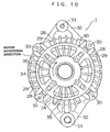
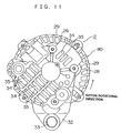
- Fig. 9 is a side sectional view of a conventional vehicular ac generator, Fig. 10 is a front view of the front bracket shown in Fig. 9, Fig. 11 is a front view of the rear bracket shown in Fig. 9 and Fig. 12 is a perspective view of a rotor.
- This ac generator comprises a case 3 composed of a
front bracket 1 and arear bracket 2 made of aluminium, ashaft 6 disposed within the case 3 and having secured to its one end portion apulley 4, arotor 7 of the Lundell type fixed to theshaft 6, afan 5 secured to the opposite side of therotor 7, a pair ofbrushes 10 in a sliding-contact relationship with theslip ring 9, a brush holder 11 housing thebrushes 10, acommutator 12 electrically connected to thestator 8, aheat sink 16 mounted to the brush holder 11 and aregulator 17 bonded to theheat sink 16 and regulating the magnitude of the ac voltage generated at thestator 8. - The
rotor 7 comprises arotor coil 13 through which an electric current is supplied to generate a magnetic flux and apole core 14 positioned over therotor coil 13, where magnetic poles are formed by the magnetic flux. Thepole core 14 is composed of a pair of a firstpole core member 18 and a secondpole core member 19 meshing with each other. The firstpole core member 18 and the secondpole core member 19 comprise pawl-shaped magnetic poles mad of iron and in the shape of a pawl. The neighboring pawl-shapedmagnetic poles magnetic poles rotor coil 13 is defined. - The
stator 8 comprises astator core 15 and astator coil 81 which is an electrical conductor wound on thestator core 15 and in which an ac power is generated due to the change in the magnetic flux in therotor coil 13 as therotor 7 rotates. - The
rectifier 12 comprises adiode 26 for rectifying the ac current generated in thestator 8 into a dc current and aheat sink 27 for dissipating the heat generated at thediode 26. - As shown in Fig. 10, the
front bracket 1 has disposed at an outer circumferential portion of the bracket main body 80 a plurality ofexhaust ports 29 formed by a plurality ofexhaust port ribs 28. Inside of theexhaust port 29,intake ports 34 are defined by a plurality ofintake ribs 35. Also, at the outer circumferential portion of the bracketmain body 80, throughholes 30 are formed at four positions spaced by 90°.Bolts 31 are inserted into these throughholes 30 and thread-engaged into therear bracket 2, whereby therear bracket 2 together with thefront bracket 1 holds thestator core 15 therebetween. Also, mountingholes 33 are provided at a pair ofmounting leg portions 32 arranged in the V-shape. Bolts (not shown) are passed through themounting holes 33 and thread-engaged with the engine main body (not shown), whereby the vehicular ac generator is secured to the engine main body. - Also as for the
rear bracket 2, as illustrated in Fig. 11, similarly to thefront bracket 1, theexhaust ports 29 are defined in the outer circumferential portion of the bracketmain body 80 by the plurality ofexhaust port ribs 28 and theintake ports 34 are defined in side of theexhaust ports 29 by theintake port ribs 35. Also, mountingleg portions 32 having themounting holes 33 corresponding to thefront bracket 1 are provided. - According to the vehicular ac generator having the above structure, an electric current is supplied form a battery (not shown) to the
rotor coil 13 through thebrush 10 and theslip ring 9 to generate a magnetic flux, thereby magnetizing the pawl-shapedmagnetic pole 20 of the firstpawl core member 18 in the N-pole and the pawl-shapedmagnetic pole 21 of the secondpawl core member 19 into the S-pole. On the other hand, thepulley 4 is driven by the engine and theshaft 6 causes the rotation of therotator 7 to rotate, so that a rotating field is applied to thestator coil 81 to generate an electro-motive force in thestator coil 81. This ac electro-motive force is rectified into a dc current through therectifier 12 and regulated in its magnitude by theregulator 17 to thereby charge the battery. - The
rotor coil 13 and thestator coil 81 always generate heat during the power generation. On the other hand, thefan 5 is rotating for dissipating the heat generated by the power generation. - That is, as shown in Fig. 9, the cooling air sucked in the axial direction through the
intake ports 34 on the side of thefront bracket 1 flows between theintake port ribs 35 deflected into the centrifugal direction by thefan 5, cools the front side end positron of thestator coil 81 and is exhausted to the outside through theexhaust ports 29 between theexhaust port ribs 28. Also, the cooling air sucked through theintake ports 29 defined between theexhaust port ribs 28 flows between theintake port rib 35, flows through theheat sink 27 of therectifier 12 and theheat sink 16 of theregulator 17, deflected by thefan 5 in the centrifugal direction, cools the rear side of thestator coil 81 and is exhausted to the outside through theexhaust ports 29 of therear bracket 2. - As for the
fan 5, thecentrifugal fan 5 having a plurality offan blades 55 is used as illustrated in Fig. 12, so that the air flow is deflected by thefan blades 55 at right angles and exhausted in the axial direction, generating pressure oscillation due to the conflicts between thefan blades 55 and the air at the flow incoming portion, giving an adverse effect in the wind noise. Also, anannular plate 56 fastened to connect the tips of the fan blades together is provided for the purpose of noise reduction. - It is to be noted that the intake ports ribs 29, the exhaust port ribs 35 and the front and
rear brackets stator 8 to the front and therear brackets - The exhaust port ribs 28 of the front and
rear brackets intake port ribs 35 of thefront bracket 1 have not had any inclination with respect to the radiation line from the rotational axis. With such the structure, a air flow resistance relative to the direction of the absolute velocity of the cooling air discharged from thefan 5 of therotor 7 is large and the flow rate has been limited, so that the cooling efficiency has been poor. Therefore, the temperature rise is increased and, as a result, the power output had to be limited. Also, as for theintake ports 34, although the air flows with an inclination due to the whirling component of the incoming air generated by the rotation of thefan 5, theintake port ribs 35 cause the air flow resistance to be large, resulting in the decrease in air flow amount. - Also, since the exhaust port ribs 28 and the
intake port ribs 35 have not been in line with the direction of the absolute velocity of the cooling air discharged from thefan 5, the interfering noise was increased. - This invention has been made in order to resolve the above-discussed problems and has as its object the provision of a vehicular ac generator of a low noise and high cooling efficiency and capable of being increased in output power by selecting optimum values of the angles, thickness and the like of the exhaust port ribs and the intake port ribs of the bracket.
- In order to achieve the above object, the present invention, which is defined in
claim 1 below, resides in a vehicular ac generator comprising a case composed of a pair of opposing brackets having exhaust port ribs defining a plurality of exhaust ports and intake port ribs disposed inner side of the exhaust ports and defining a plurality of intake ports; a rotor rotatably disposed within the case; a stator secured within the case and having a stator coil in which an ac current is generated by a rotating magnetic field generated by the rotor; and a pair of fan secured at the axially opposite sides of the rotor for generating a flow of cooling air sucked through the intake ports of the bracket to cool the stator coil and exhausted to outside from the exhaust ports; characterized in that the exhaust port ribs of at least one of the brackets are tilted from 20° to 50° in the direction of rotation of the rotor with respect to the radial direction of the generator. - The rib thickness of the exhaust port ribs in the normal plane of the tilt direction of the exhaust port ribs may be equal to or less than 50 % of the exhaust port width.
- When the rotor rotates the fan rotates to suck air from the intake ports of the bracket which cools the rear side end portions and the front side end portions of the stator coil and which exhausts from the exhaust ports. The air exhausted from the exhaust ports is exhausted at a predetermined angle with respect to the radial line from the rotary axis due to the whirling component due to the rotation of the fan.
- According to experiments, as the tilt angle of the exhaust port ribs is increased, the power output increases up to about 50° which is believed to be the most preferable angle and, the further increase of the tilt angle causes the output to sharply decrease. On the other hand, the wind noise sound pressure sharply is decreased up until about 20°, kept about constant from 20° to 60° and has a transition point at about 60° from where it is decreased again.
- Therefore, when the tilt angle of the exhaust port ribs is set at from 20° to 50° in the direction of rotation of the rotor, both the power output and the wind noise can be made satisfactory.
- Also, the rib thickness of the exhaust port ribs in the normal plane of the tilt direction of the exhaust port ribs may preferably be equal to or less than 50 % of the exhaust port width.
- According to the experiments, as the rib thickness relative to the exhaust port width is increased, the power output is gradually increased and, with a transition point at about 0.5, it is sharply decrease. Contrary to this, the wind noise does not change much because the angle is set at from 20° to 50° which is close to the velocity vector of the exhausted cooling air.
- The intake port ribs of at least one of the brackets are tilted from 25° to 35° in the direction opposite to the direction of rotation of the rotor with respect to the radial line from a rotational axis.
- As for the intake ports, the air flow is also sucked at a predetermined tilt angle with respect to the radial line from the rotary axis due to the whirling component due to the rotation of the fan, so that there is an optimum angle as in the exhaust port ribs. According to the experiments, when the tilt angle of the intake port ribs is set at from 20° to 50° both the power output and the wind noise can be made satisfactory.
- Also, the side surfaces of the intake port ribs on side of the rotational direction of the fan are tilted from 10° to 20° with respect to the axis in a plane perpendicular to the intake port ribs.
- With such arrangement, the incoming air flow is smoothly introduced.
- The ratio of the width in the circumferential direction of the intake port may be made equal to the ratio between the diameter of the innermost edge of the ports and the diameter of the outermost edge of the ports.
- Also, a taper of from 40° to 50° may be provided in the inner circumferential surface on the outermost diameter side of the intake port so that the diameter gradually decreases from the outer air side toward the case inner portion.
- Further, the fan may be provided with an annular plate connecting the tip of each fan blade and wherein the taper in the inner circumferential surface on the outermost diameter side of the intake port is formed with the inner diameter of said annular plate used as the base point.
- The present invention will become more readily apparent from the following detailed description of the preferred embodiments of the present invention taken in conjunction with the accompanying drawings, in which:
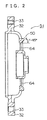
- Fig. 1(a) is a front view of the front bracket of the vehicular ac generator of one embodiment of the present invention and Fig. 1(b) is a sectional view taken along line B - B of Fig. 1(a);
- Fig. 2 is a sectional view of the front bracket of Fig. 1;
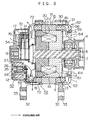
- Fig. 3 is a sectional side view of the vehicular ac generator to which the front bracket shown in Fig. 1 is applied;
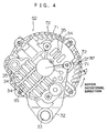
- Fig. 4 is a front view of the rear bracket of the vehicular ac generator of Fig. 3;
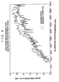
- Fig. 5 is a graph for showing the comparison of the relationship between the rotating speed and the wind sound pressure level of the embodiment of the present invention and the conventional example to indicate the wind noise reducing effect of the embodiment of the present invention;
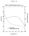
- Fig. 6 is a graph showing the experiment results of the relationship between the tilt angle of the exhaust port ribs and the output and the noise sound pressure level of the embodiment of the present invention;
- Fig. 7 is a graph showing the measurement results of the output and the sound pressure with a parameter of the ratio of the rib thickness of the exhaust port rib relative to the width of the exhaust port of the embodiment of the present invention;
- Fig. 8 is a graph for showing the comparison of the relationship between the rotating speed and the wind sound pressure level of the embodiment of the present invention and the conventional example to indicate the wind noise reducing effect of the embodiment of the present invention;
- Fig. 9 is a sectional side view of the conventional vehicular ac generator;
- Fig. 10 is a front view of the conventional front bracket;
- Fig. 11 is a front view of the conventional rear bracket; and
- Fig. 12 is a perspective view of the conventional rotor.
- In order to describe the present invention in detail, embodiments of the present invention will described in conjunction with the accompanying drawings. In the following description, the components identical to those of the conventional example will be described with the same reference numerals attached thereto.
- Fig. 1 is a front view of the front bracket of one embodiment of the present invention, Fig. 2 is a sectional view of the front bracket of Fig. 1, Fig. 3 is a sectional side view of the vehicular ac generator and Fig. 4 is a front view of the rear bracket of the vehicular ac generator of Fig. 3;
- The vehicular ac generator comprises, as shown in Fig. 3, a
case 53 composed of afront bracket 51 and arear bracket 52 made of aluminum, ashaft 6 disposed within thecase 53 and having secured to its one end portion apulley 4, arotor 7 of the Lundell type fixed to theshaft 6, afan 5 secured to the opposite sides of therotor 7, astator 8 secured to the inner wall surface of thecase 53, aslip ring 9 secured to the other end portion of theshaft 6 for supplying an electric current to therotor 7, a pair ofbrushes 10 in a sliding-contact relationship with theslip ring 9, a brush holder 11 housing thebrushes 10, acommutator 12 electrically connected to thestator 8, aheat sink 16 mounted to the brush holder 11 and aregulator 17 bonded to theheat sink 16 and regulating the magnitude of the ac voltage generated at thestator 8. - The
rotor 7 comprises arotor coil 13 through which an electric current is supplied to generate a magnetic flux and apole core 14 positioned over therotor coil 13, where an magnetic poles are formed by the magnetic flux. Thepole core 14 is composed of a pair of a firstpole core member 18 and a secondpole core member 19 meshing with each other. The firstpole core member 18 and the secondpole core member 19 comprises pawl-shaped magnetic poles made of iron and in the shape of a pawl. The neighboring pawl-shapedmagnetic poles magnetic poles rotor coil 13 is defined. - The
stator 8 comprises astator core 15 and astator coil 81 which is an electrical conductor wound on thestator core 15 and in which an ac power is generated due to the change in the magnetic flux in therotor coil 13 as therotor 7 rotates. - The
rectifier 12 comprises adiode 26 for rectifying the ac current generated in thestator 8 into a dc current and aheat sink 27 for dissipating the heat generated at thediode 26. - As shown in Figs. 1 and 2, the
front bracket 51 has disposed at an outer circumferential portion of the bracket main body 50 a plurality ofexhaust ports 62 formed by a plurality ofexhaust port ribs 61. Inside of theexhaust port 62,intake ports 34 are defined by a plurality ofintake ribs 63. Also, at the outer circumferential portion of the bracketmain body 80, throughholes 30 are formed at four positions spaced by 90°.Bolts 31 are inserted into these throughholes 30 and thread-engaged into therear bracket 2, whereby therear bracket 2 together with thefront bracket 1 holds thestator core 15 therebetween. Also, mountingholes 33 are provided at a pair of mountingleg portions 32 arranged in the V-shape. Bolts (not shown) are passed through the mountingholes 33 and thread-engaged with the engine main body (not shown), whereby the vehicular ac generator is secured to the engine main body. - Also as for the
rear bracket 52 similarly to thefront bracket 51, theexhaust ports 72 are defined in the outer circumferential portion of the bracketmain body 50 by the plurality ofexhaust port ribs 28 and theintake ports 34 are defined in side of theexhaust ports 72 by theintake port ribs 35. Also, mountingleg portions 32 having the mountingholes 33 corresponding to thefront bracket 51 are provided. - According to the vehicular ac generator having the above structure, an electric current is supplied form a battery (not shown) to the
rotor coil 13 through thebrush 10 and theslip ring 9 to generate a magnetic flux, thereby magnetizing the pawl-shapedmagnetic pole 20 of the firstpawl core member 18 in the N-pole and the pawl-shapedmagnetic pole 21 of the secondpawl core member 19 into the S-pole. On the other hand, thepulley 4 is driven by the engine and theshaft 6 causes the rotation of therotator 7 to rotate, so that a rotating field is applied to thestator coil 81 to generate an electro-motive force in thestator coil 81. This ac electro-motive force is rectified into a dc current through therectifier 12 and regulated in its magnitude by theregulator 17 to thereby charged in the battery. - The
rotor coil 13 and thestator coil 81 always generate heat during the power generation. On the other hand, thefan 5 is rotating for dissipating the heat generated by the power generation. - That is, as shown in Fig. 3, the cooling air sucked in the axial direction through the
intake ports 64 on the side of thefront bracket 51 flows between theintake port ribs 63 deflected into the centrifugal direction by thefan 5, cools the front side end positron of thestator coil 81 and is exhausted to the outside through theexhaust ports 62 between theexhaust port ribs 61. Also, the cooling air sucked through theintake ports 34 on therear bracket 52 side flows between theintake port rib 35, flows through theheat sink 27 of therectifier 12 and theheat sink 16 of theregulator 17, deflected by thefan 5 in the centrifugal direction, cools the rear side end of thestator coil 81 and is exhausted to the outside through the exhaust ports 79 of therear bracket 52. - As for the
fan 5, thecentrifugal fan 5 having a plurality offan blades 55 is used, so that the air flow is deflected by thefan blades 55 at right angles and exhausted in the axial direction, generating pressure oscillation due to the conflicts between thefan blades 55 and the air at the flow incoming portion, giving an adverse effect in the wind noise. Also, anannular plate 56 fastened to connect the tips of the fan blades together is provided for the purpose of noise reduction. - According to this embodiment, as for the
exhaust port ribs front bracket 51 and therear bracket 52, the tilt angle α on the rotation direction side of the rotor with respect to the radial line from the rotary axis (radial direction of the rotor) is set α = 20° to 50°. In particular, in this embodiment, theexhaust port ribs 61 of thefront bracket 51 is set α = 40° and theexhaust port ribs 71 of therear bracket 52 is set α = 30°. - Also, the ratio T/L between the exhaust port width L and the thickness of the rib T in the normal plane of the tilt direction of the exhaust port ribs are equal to or less than 50 % and preferably 0.4.
- Further, in the
front bracket 51, the ratio between thecircumferential widths 11 and 12 of the outermost portion and the innermost portion of theintake port 64 is made equal to the ratio between the port innermost diameter d1 and the port outermost diameter d2, and the tilt angle θ of theintake port ribs 63 toward the direction opposite to the rotational direction of the rotor with respect to the radial line from the axis is set at from 25° to 35° and is particularly set at 30° in this embodiment. - Also, the tilt angle β of side surfaces of the intake port ribs on side of the rotational direction of the fan with respect to the axis in a normal plane to the
intake port ribs 63 are set β = 10° to 20°, and particularly 15° in this embodiment. - A taper angle γ of from 40° to 50° is provided in the inner circumferential surface on the outermost diameter side of the
intake port 64 so that the diameter gradually decreases from the outer air side toward the inner portion of thecase 53 with the inner diameter of the annular plate of thefan 5 as a starting point. In this embodiment, γ is set at 45°. - Also, as for the
intake ports 34 and theintake port ribs 35 on the rear side, no angle is provided and they are open in the axial direction as in the conventional design. - During the designing of the generator of the present invention, in view of the previously discussed problems of the conventional design, the absolute velocity direction of cooling air on the intake and the exhaust sides is visualized by the tuft method. This method is to inspect the velocity vector direction of the cooling air on the basis of the stream direction of the tufts. This inspection was conducted at constant 3000 rpm of the generator rotating speed at which the temperature of the
stator 8 of which output is limited and the diode of therectifier 12 reaches at the maximum points. - According to this, it was determined that the cooling air flow is introduced with a large inclination or tilt due to the whirling component due to the rotation of the
rotor 7. It was also determined according to the results of the experiments that the air flows, at theintake port 64 on the front side, with the correspondence with each set angle of theintake port ribs 63, θ = about 30° and β = about 15°, at theexhaust port 62 of the front side, with the correspondence with each set angle of theexhaust port ribs 61, α = about 40° and at theexhaust port 72 on the rear side, α = about 30°. It is to be noted that as to theintake port 35 on the rear side the flow was parallel to the axial direction. The reason for this is considered that the gap between therear bracket 52 and thefan 5 is large and that theregulator 17, therectifier 12 and the like which are components to be cooled are disposed between therear bracket 52 and thefan 5. - When the rotational speed is changed up and down, this angle fluctuates by ± 5° from this value and the most suitable angle exists actually at the respective rotational speed, it is reasonable to determine the optimum angle a generator rotational speed at around 300 rpm which is the highest temperature point for the
stator 8 and the diode of therectifier 12. - As the results of the measurement experiments of the power output and the temperature with the set angles of the above embodiment, the alternator having the fan with the plate utilizing this bracket has the temperature reduction effect of 25 °C for the
stator rectifier regulator 17 as compared to the one employing the conventional bracket, and when the temperature rise is made equal to that of the conventional design to increase the power output, output increase corresponding to 3A was obtained. - Fig. 5 illustrates the data for the wind noise.
- According to this, a high frequency component annoying to ear was reduced by maximum 20 dB according to the present invention as compared to the conventional design, and at 7000 to 13000 rpm the overall value was also reduced by 2 dB.
- The application of the bracket of this embodiment has realized the generator superior in wind noise, power output and temperature.
- Next, in order to establish the design guides for the ac bracket of such the vehicular ac generator, experiments were conducted with models that were manufactured using the ratio T/L of the thickness of the
exhaust ribs exhaust ports exhaust port ribs - Fig. 6 illustrates the results of measurement of the power output and the wind noise sound pressures with the parameter of the T/L = 0.4 constant as well as the tilt angle α of the
exhaust port ribs - The output is the value when the temperature rise at the rotation speed of 3000 rpm is made equal and the wind noise is the value at 10000 rpm. The specimen used at this has the same tilt angle α for both the
exhaust port ribs 61 on the front side and theexhaust port ribs 71 on the rear side. According to this, as the tilt α is increased, the output is increased up to about 50° which is considered to be optimum angle and then sharply deteriorate beyond it. - The reason for this may be considered that, although the velocity vector of the cooling exhaust air includes the whirling component and the vector component in the radial direction which is the direction of exhaustion, the side surface of the exhaust port rib is tilted in the direction to which the exhaustion is efficiently achieved and is open to the vector component in the radial direction up to about 50° of the velocity vector of the cooling exhaust air, but when the angle exceeds this, a large resistance occurs with respect to the velocity vector in the radial direction and the wind flow rate is abruptly decreased.
- On the other hand, the wind noise sound pressure is sharply decreased up to about 20°, is flat from 20° to 60° and has a transition point at about 60° from where it is decreased again. This is considered that, the up to about 20° the sound pressures are sharply decreased due to the decrease in interference between the exhaust port ribs and the exhausting air and that the further decrease of the sound pressures at about 60° is due to the large resistance provided by the exhaust port ribs which causes the decrease in the exhausting air flow rate.
- According to these results, by setting the tilt angle α of the
exhaust port ribs - Fig. 7 illustrates, as similarly to Fig. 6, the results of measurement of the power output and the wind noise sound pressures with the parameter of the ratio T/L of the exhaust port rib with respect to the exhaust port under the conditions that the tilt angle α of the exhaust port ribs is constant (α = 40°), the thickness T of the exhaust port ribs is constant (T = 2[mm]).
- According to this, the output gradually increases as the ratio T/L is increased and then at the transition point at about 0.5 it sharply decreases. This is considered because the number of the exhaust port ribs increases as T/L is increased under a predetermined condition of a constant exhaust port rib thickness, whereby effect of the heat conducted from the stator to the exhaust port ribs as previously described being dissipated from the exhaust port ribs. However, it is considered that, even if T/L is made equal to or larger than 0.5, the exhaust ports become smaller, the power output tends to deteriorate because of the decrease in air flow rate due to increase in flow resistance.
- Contrary to this, no significant change was observed in the wind noise because the tilt angle α of the exhaust port ribs is set at a constant value (40°) dose to the velocity vector of the cooling exhaust air. From this results, it will be well understood that the deterioration of the output can be suppressed by making T/L equal to or less than 0.5.
- From the above, a generator superior in power output as well as in wind noise property can be provided by arranging such that the exhaust port ribs are tilted from 20° to 50° in the direction of rotation of the rotor and that the rib thickness of the exhaust port ribs in the normal plane of the tilt direction of the exhaust port ribs are equal to or less than 50 % of the exhaust port width.
- Although the optimum rib configuration for the exhaust port has been disclosed in the above, the
intake ports 64 of thefront bracket 51 can also be made to have a low wind noise by, as shown in Fig. 1, setting the tilt angle θ of theintake port ribs 63 toward the direction opposite to the rotational direction of the rotor with respect to the radial line from the axis is set at from 25° to 35°, the ratio between thecircumferential widths 11 and 12 of the outermost portion and the innermost portion of theintake port 64 is made equal to the ratio between the port innermost diameter d1 and the port outermost diameter d2, the tilt angle β of side surfaces of the intake port ribs on the side of the rotational direction of thefan 5 are set β = 10° to 20° and by setting the taper angle γ of from 40° to 50° is provided in the axial direction with the inner diameter of the annular plate of thefan 5 as a starting point to substantially match the velocity vector of the incoming air, thereby reducing the wind noise. This effect of reducing the wind noise is illustrated in Fig. 8. - Differing from the exhaust port, the wind noise was reduced in pitch tone noise due to the
fan 5. Particularly, since the inner circumferential surface of the outermost diameter portion is tapered having a starting point at the inner diameter of the annular plate of thefan 5, the air is stream-lined without impinging against the annular plate and introduced smoothly into the fan blade portion. - Although the
intake ports 34 and theintake port ribs 35 of therear bracket 52 of this embodiment are not tilted as in the conventional design, they can be constructed similarly to theintake ports 63 and theintake port ribs 64 on the' side of thefront bracket 51 as long as the clearance between therear bracket 52 and thefan 5 is equal to that between thefront bracket 51 and thefan 5. - Also, during the shot-blasting of the bracket for eliminating burrs and for preventing the damages to the bracket when their rib portions are brought into contact due to biting, the pitch of the exhaust ports may be made uneven within the above range whereby the breakage or the like can be prevented without deteriorating the cooling and low noise properties.
- As has been described, the vehicular ac generator of the present invention is useful as an electric power supply source for various electric devices of an automobile.
Claims (3)
- A vehicular ac generator comprising a case composed of a pair of opposing brackets having exhaust port ribs defining a plurality of exhaust ports and intake port ribs disposed inner side of said exhaust ports and defining a plurality of intake ports;
a rotor rotatably disposed within said case;
a stator secured within said case and having a stator coil in which an ac current is generated by a rotating magnetic field generated by said rotor; and
a pair of fan secured at the axially opposite sides of said rotor for generating a flow of cooling air sucked through the intake ports of said bracket to cool said stator coil and exhausted to outside from the exhaust ports;
characterized in that said exhaust port ribs of at least one of said brackets are tilted from 20° to 50° in the direction of rotation of said rotor with respect to the radial direction of the generator,
intake port ribs of at least one of said brackets are tilted from 25° to 35° in the direction radially outwardly and opposite to the direction of rotation of said rotor with respect to the radial line form a rotational axis,
side surfaces of said intake port ribs on side of the rotational direction of the fan are tilted from 10° to 20° with respect to the axis in a plane perpendicular to said intake port ribs; and
that the ratio between the circumferential widths of the outermost portion and the innermost portion of the intake port is made equal to the ratio between the port innermost diameter and the port outermost diameter. - A vehicular ac generator as claimed in claim 1, wherein a taper of from 40° to 50° is provided in the inner circumferential surface on the outermost diameter side of said intake port so that the diameter gradually decreases from the outer air side toward the case inner portion.
- A vehicular ac generator as claimed in claim 2, wherein the fan is provided with an annular plate connecting the tip of each fan blade and wherein the taper in the inner circumferential surface on the outermost diameter side of the intake port is formed with the inner diameter of said annular plate used as the base point.
Applications Claiming Priority (1)
| Application Number | Priority Date | Filing Date | Title |
|---|---|---|---|
| PCT/JP1998/004120 WO2000016467A1 (en) | 1998-09-11 | 1998-09-11 | Alternating current generator for vehicles |
Publications (3)
| Publication Number | Publication Date |
|---|---|
| EP1032112A1 EP1032112A1 (en) | 2000-08-30 |
| EP1032112A4 EP1032112A4 (en) | 2001-12-05 |
| EP1032112B1 true EP1032112B1 (en) | 2006-07-05 |
Family
ID=14208985
Family Applications (1)
| Application Number | Title | Priority Date | Filing Date |
|---|---|---|---|
| EP98941850A Expired - Lifetime EP1032112B1 (en) | 1998-09-11 | 1998-09-11 | Alternating current generator for vehicles |
Country Status (5)
| Country | Link |
|---|---|
| US (1) | US6417585B1 (en) |
| EP (1) | EP1032112B1 (en) |
| KR (1) | KR100367369B1 (en) |
| DE (1) | DE69835164T2 (en) |
| WO (1) | WO2000016467A1 (en) |
Families Citing this family (27)
| Publication number | Priority date | Publication date | Assignee | Title |
|---|---|---|---|---|
| JP4118548B2 (en) * | 2001-11-06 | 2008-07-16 | 株式会社デンソー | Vehicle alternator |
| FR2841705B1 (en) * | 2002-06-28 | 2009-01-23 | Valeo Equip Electr Moteur | INTERNAL VENTILATION SYSTEM OF A ROTATING ELECTRIC MACHINE SUCH AS AN ALTERNATOR IN PARTICULAR OF A MOTOR VEHICLE |
| US6750578B2 (en) * | 2002-07-22 | 2004-06-15 | Delphi Technologies, Inc. | Rotating electrical machine |
| KR20040011075A (en) * | 2002-07-27 | 2004-02-05 | 발레오만도전장시스템스코리아 주식회사 | Front bracket structure for vehicl alternator |
| JP3982369B2 (en) * | 2002-09-12 | 2007-09-26 | 株式会社デンソー | AC generator for vehicles |
| KR20040042585A (en) * | 2002-11-15 | 2004-05-20 | 현대자동차주식회사 | An alternator for automobile |
| FR2869477B1 (en) * | 2004-03-26 | 2007-07-27 | Valeo Equip Electr Moteur | ROTATING ELECTRICAL MACHINE, IN PARTICULAR ALTERNATOR FOR A MOTOR VEHICLE, WHOSE AIR INPUTS / OUTPUTS INCLUDE INCLINED FINS WITH RESPECT TO THE BLADES OF THE FANS |
| EP1750351B1 (en) * | 2004-05-28 | 2019-12-04 | Mitsubishi Denki Kabushiki Kaisha | Alternator for vehicle |
| MY138646A (en) * | 2005-02-23 | 2009-07-31 | Panasonic Corp | Motor and electric apparatus equipped with a conductive pin for suppressing electrolytic corrosion |
| JP2006271015A (en) * | 2005-03-22 | 2006-10-05 | Denso Corp | Alternator for vehicle |
| JP4548264B2 (en) * | 2005-08-01 | 2010-09-22 | 株式会社デンソー | Vehicle alternator |
| JP4497090B2 (en) * | 2005-12-21 | 2010-07-07 | 株式会社デンソー | Vehicle alternator |
| DE102006052415A1 (en) * | 2006-11-07 | 2008-05-08 | Robert Bosch Gmbh | Bearing device for venting machine, has bearing shield including connecting rod in bearing hub, where bearing rod includes recess, and another connecting rod including chamfered edge in inner side of bearing shield in assembled condition |
| JP5047697B2 (en) * | 2007-06-07 | 2012-10-10 | 株式会社マキタ | Electric tool |
| JP4375456B2 (en) * | 2007-07-26 | 2009-12-02 | 株式会社デンソー | AC generator for brushless vehicles |
| MX340199B (en) * | 2012-06-28 | 2016-06-30 | Mitsubishi Electric Corp | Rotating electrical machine for vehicle. |
| JP5542984B1 (en) * | 2013-02-18 | 2014-07-09 | 三菱電機株式会社 | AC generator for vehicles |
| CN105027398A (en) * | 2013-03-06 | 2015-11-04 | 三菱电机株式会社 | Power electronic module, method for producing such a module, and rotating electrical machine of a motor vehicle comprising same |
| JP2014236616A (en) | 2013-06-04 | 2014-12-15 | 三菱電機株式会社 | Dynamo-electric machine |
| JP5751319B2 (en) * | 2013-12-10 | 2015-07-22 | 三菱電機株式会社 | Rotating electric machine |
| KR101970737B1 (en) * | 2014-01-07 | 2019-04-22 | 한온시스템 주식회사 | Motor |
| JP5805233B2 (en) * | 2014-02-17 | 2015-11-04 | 三菱電機株式会社 | AC generator for vehicles |
| JP6230649B2 (en) * | 2016-04-28 | 2017-11-15 | 三菱電機株式会社 | Rotating electric machine for vehicles |
| US11788626B2 (en) | 2019-12-30 | 2023-10-17 | Eaton Intelligent Power Limited | Dynamic seal rotor |
| CN111555521B (en) * | 2020-05-14 | 2021-08-06 | 太仓荣邦金属制品有限公司 | High-temperature-resistant and corrosion-resistant aluminum alloy automobile engine end cover and preparation process thereof |
| CN112928849B (en) * | 2021-01-22 | 2022-02-15 | 珠海格力电器股份有限公司 | Motor fan cover and motor |
| JP7135138B2 (en) * | 2021-02-22 | 2022-09-12 | 三菱電機株式会社 | Rotating electric machine |
Family Cites Families (16)
| Publication number | Priority date | Publication date | Assignee | Title |
|---|---|---|---|---|
| JPS5657664U (en) * | 1979-10-12 | 1981-05-18 | ||
| JPS5671446A (en) * | 1979-11-14 | 1981-06-15 | Toshiba Corp | Bearing bracket for rotary electric machine |
| JPS56129548A (en) * | 1980-03-12 | 1981-10-09 | Toshiba Corp | Bearing bracket for rotary electric machine |
| JPS576551A (en) | 1980-06-12 | 1982-01-13 | Nippon Denso Co Ltd | Ac generator for vehicle |
| JPS57186168U (en) * | 1981-05-20 | 1982-11-26 | ||
| DE3514207A1 (en) * | 1985-04-19 | 1986-10-30 | Promotec GmbH Ingenieurbüro, Industrievertretungen, 7000 Stuttgart | Dynamo having a rotor wheel for sucking in cooling air for motor vehicles |
| US4684835A (en) * | 1985-10-07 | 1987-08-04 | Ametek, Inc. | Motor cooling fan housing |
| US5095235A (en) * | 1989-12-04 | 1992-03-10 | Mitsubishi Denki K.K. | Vehicle ac generator |
| JPH04140043A (en) * | 1990-09-28 | 1992-05-14 | Mitsubishi Electric Corp | Ac generator for vehicle |
| JPH04140042A (en) * | 1990-09-28 | 1992-05-14 | Mitsubishi Electric Corp | Ac generator for vehicle |
| JP2622215B2 (en) * | 1991-10-15 | 1997-06-18 | 三菱電機株式会社 | AC generator for vehicles |
| JP2661545B2 (en) * | 1993-07-15 | 1997-10-08 | 株式会社デンソー | Rotating electric machine |
| JP2828587B2 (en) * | 1993-12-28 | 1998-11-25 | 三菱電機株式会社 | Cooling fan for vehicle alternator |
| JPH09172752A (en) * | 1995-12-19 | 1997-06-30 | Denso Corp | Ac generator |
| FR2745439B1 (en) * | 1996-02-28 | 1998-04-10 | Valeo Equip Electr Moteur | AUTOMOTIVE VEHICLE ALTERNATOR WITH INTERNAL VENTILATION PROVIDED WITH AN IMPROVED BEARING |
| JP3900677B2 (en) * | 1998-05-14 | 2007-04-04 | 株式会社デンソー | AC generator for vehicles |
-
1998
- 1998-09-11 WO PCT/JP1998/004120 patent/WO2000016467A1/en active IP Right Grant
- 1998-09-11 EP EP98941850A patent/EP1032112B1/en not_active Expired - Lifetime
- 1998-09-11 KR KR10-2000-7004821A patent/KR100367369B1/en not_active IP Right Cessation
- 1998-09-11 DE DE69835164T patent/DE69835164T2/en not_active Expired - Lifetime
-
2000
- 2000-05-11 US US09/568,497 patent/US6417585B1/en not_active Expired - Lifetime
Also Published As
| Publication number | Publication date |
|---|---|
| DE69835164T2 (en) | 2007-05-31 |
| DE69835164D1 (en) | 2006-08-17 |
| US6417585B1 (en) | 2002-07-09 |
| WO2000016467A1 (en) | 2000-03-23 |
| KR100367369B1 (en) | 2003-01-09 |
| KR20010031756A (en) | 2001-04-16 |
| EP1032112A1 (en) | 2000-08-30 |
| EP1032112A4 (en) | 2001-12-05 |
Similar Documents
| Publication | Publication Date | Title |
|---|---|---|
| EP1032112B1 (en) | Alternating current generator for vehicles | |
| US6198187B1 (en) | Automotive alternator | |
| US5710467A (en) | Alternator | |
| KR100364017B1 (en) | Automotive alternator | |
| JP2661545B2 (en) | Rotating electric machine | |
| US7741739B2 (en) | Automotive alternator | |
| JP2001268869A (en) | Alternating current generator | |
| US6018205A (en) | Vehicle alternator | |
| JPH09289756A (en) | Alternator | |
| JP2001298888A (en) | Ac generator for vehicle | |
| KR20010014727A (en) | Alternator | |
| JP3783832B2 (en) | AC generator for vehicles | |
| US6114793A (en) | Automotive alternator | |
| JP3294497B2 (en) | Alternator | |
| JPH09172752A (en) | Ac generator | |
| JP2004104955A (en) | Alternator for vehicle | |
| US7619336B2 (en) | Vehicle-use generator with reduced fan noise | |
| KR100234063B1 (en) | Alternator for a vehicle | |
| JP2634342B2 (en) | AC generator for vehicles | |
| JPH09201009A (en) | Ac generator | |
| JPH11332178A (en) | Alternating-current generator for vehicle | |
| JP2797823B2 (en) | AC generator for vehicles | |
| EP1357659B1 (en) | Automotive alternator | |
| KR0147937B1 (en) | Low noise type ac generator for a vehicle | |
| JPH04183244A (en) | Alternator for vehicle |
Legal Events
| Date | Code | Title | Description |
|---|---|---|---|
| PUAI | Public reference made under article 153(3) epc to a published international application that has entered the european phase |
Free format text: ORIGINAL CODE: 0009012 |
|
| 17P | Request for examination filed |
Effective date: 20000502 |
|
| AK | Designated contracting states |
Kind code of ref document: A1 Designated state(s): DE FR GB IT |
|
| A4 | Supplementary search report drawn up and despatched |
Effective date: 20011019 |
|
| AK | Designated contracting states |
Kind code of ref document: A4 Designated state(s): DE FR GB IT |
|
| RIC1 | Information provided on ipc code assigned before grant |
Free format text: 7H 02K 9/06 A, 7H 02K 5/20 B |
|
| 17Q | First examination report despatched |
Effective date: 20030915 |
|
| GRAP | Despatch of communication of intention to grant a patent |
Free format text: ORIGINAL CODE: EPIDOSNIGR1 |
|
| RAP1 | Party data changed (applicant data changed or rights of an application transferred) |
Owner name: MITSUBISHI DENKI KABUSHIKI KAISHA |
|
| GRAS | Grant fee paid |
Free format text: ORIGINAL CODE: EPIDOSNIGR3 |
|
| GRAA | (expected) grant |
Free format text: ORIGINAL CODE: 0009210 |
|
| AK | Designated contracting states |
Kind code of ref document: B1 Designated state(s): DE FR GB IT |
|
| REG | Reference to a national code |
Ref country code: GB Ref legal event code: FG4D |
|
| REF | Corresponds to: |
Ref document number: 69835164 Country of ref document: DE Date of ref document: 20060817 Kind code of ref document: P |
|
| REG | Reference to a national code |
Ref country code: GB Ref legal event code: 727 |
|
| ET | Fr: translation filed | ||
| PLBE | No opposition filed within time limit |
Free format text: ORIGINAL CODE: 0009261 |
|
| STAA | Information on the status of an ep patent application or granted ep patent |
Free format text: STATUS: NO OPPOSITION FILED WITHIN TIME LIMIT |
|
| 26N | No opposition filed |
Effective date: 20070410 |
|
| REG | Reference to a national code |
Ref country code: GB Ref legal event code: 727A |
|
| REG | Reference to a national code |
Ref country code: GB Ref legal event code: 746 Effective date: 20080125 |
|
| REG | Reference to a national code |
Ref country code: GB Ref legal event code: S27 |
|
| REG | Reference to a national code |
Ref country code: GB Ref legal event code: S47 Free format text: CANCELLATION OF ENTRY; APPLICATION BY FILING PATENTS FORM 15 WITHIN 4 WEEKS FROM THE DATE OF PUBLICATION OF THIS JOURNAL |
|
| REG | Reference to a national code |
Ref country code: GB Ref legal event code: S47 Free format text: ENTRY CANCELLED; NOTICE IS HEREBY GIVEN THAT THE ENTRY ON THE REGISTER 'LICENCES OF RIGHT' UPON THE UNDER MENTIONED PATENT WAS CANCELLED ON 17 FEBRUARY 2011ALTERNATING CURRENT GENERATOR FOR VEHICLES |
|
| PGFP | Annual fee paid to national office [announced via postgrant information from national office to epo] |
Ref country code: DE Payment date: 20140903 Year of fee payment: 17 |
|
| REG | Reference to a national code |
Ref country code: DE Ref legal event code: R084 Ref document number: 69835164 Country of ref document: DE |
|
| REG | Reference to a national code |
Ref country code: GB Ref legal event code: 746 Effective date: 20141104 |
|
| PGFP | Annual fee paid to national office [announced via postgrant information from national office to epo] |
Ref country code: GB Payment date: 20140910 Year of fee payment: 17 |
|
| REG | Reference to a national code |
Ref country code: DE Ref legal event code: R084 Ref document number: 69835164 Country of ref document: DE Effective date: 20141107 |
|
| PGFP | Annual fee paid to national office [announced via postgrant information from national office to epo] |
Ref country code: IT Payment date: 20140912 Year of fee payment: 17 |
|
| PGFP | Annual fee paid to national office [announced via postgrant information from national office to epo] |
Ref country code: FR Payment date: 20140906 Year of fee payment: 17 |
|
| REG | Reference to a national code |
Ref country code: DE Ref legal event code: R119 Ref document number: 69835164 Country of ref document: DE |
|
| PG25 | Lapsed in a contracting state [announced via postgrant information from national office to epo] |
Ref country code: IT Free format text: LAPSE BECAUSE OF NON-PAYMENT OF DUE FEES Effective date: 20150911 |
|
| GBPC | Gb: european patent ceased through non-payment of renewal fee |
Effective date: 20150911 |
|
| REG | Reference to a national code |
Ref country code: FR Ref legal event code: ST Effective date: 20160531 |
|
| PG25 | Lapsed in a contracting state [announced via postgrant information from national office to epo] |
Ref country code: DE Free format text: LAPSE BECAUSE OF NON-PAYMENT OF DUE FEES Effective date: 20160401 Ref country code: GB Free format text: LAPSE BECAUSE OF NON-PAYMENT OF DUE FEES Effective date: 20150911 |
|
| PG25 | Lapsed in a contracting state [announced via postgrant information from national office to epo] |
Ref country code: FR Free format text: LAPSE BECAUSE OF NON-PAYMENT OF DUE FEES Effective date: 20150930 |