EP1034930A1 - Ink jet recording head - Google Patents
Ink jet recording head Download PDFInfo
- Publication number
- EP1034930A1 EP1034930A1 EP00112087A EP00112087A EP1034930A1 EP 1034930 A1 EP1034930 A1 EP 1034930A1 EP 00112087 A EP00112087 A EP 00112087A EP 00112087 A EP00112087 A EP 00112087A EP 1034930 A1 EP1034930 A1 EP 1034930A1
- Authority
- EP
- European Patent Office
- Prior art keywords
- pressure generating
- generating chambers
- ink
- pitch
- recording head
- Prior art date
- Legal status (The legal status is an assumption and is not a legal conclusion. Google has not performed a legal analysis and makes no representation as to the accuracy of the status listed.)
- Granted
Links
- 238000005192 partition Methods 0.000 claims abstract description 32
- 125000006850 spacer group Chemical group 0.000 claims abstract description 19
- 238000007641 inkjet printing Methods 0.000 claims abstract description 11
- 238000004891 communication Methods 0.000 claims description 20
- 239000000758 substrate Substances 0.000 claims description 13
- 238000010030 laminating Methods 0.000 abstract description 3
- 238000004519 manufacturing process Methods 0.000 description 4
- 238000010586 diagram Methods 0.000 description 3
- 238000005245 sintering Methods 0.000 description 3
- MCMNRKCIXSYSNV-UHFFFAOYSA-N Zirconium dioxide Chemical compound O=[Zr]=O MCMNRKCIXSYSNV-UHFFFAOYSA-N 0.000 description 2
- 229910010293 ceramic material Inorganic materials 0.000 description 2
- 238000007639 printing Methods 0.000 description 2
- 239000000853 adhesive Substances 0.000 description 1
- 230000001070 adhesive effect Effects 0.000 description 1
- 239000012790 adhesive layer Substances 0.000 description 1
- 239000000919 ceramic Substances 0.000 description 1
- 230000001419 dependent effect Effects 0.000 description 1
- 238000006073 displacement reaction Methods 0.000 description 1
- 238000001035 drying Methods 0.000 description 1
- 238000010438 heat treatment Methods 0.000 description 1
- 239000010410 layer Substances 0.000 description 1
- 238000000034 method Methods 0.000 description 1
- 238000000465 moulding Methods 0.000 description 1
- 239000011241 protective layer Substances 0.000 description 1
- 230000003014 reinforcing effect Effects 0.000 description 1
Images


Classifications
-
- B—PERFORMING OPERATIONS; TRANSPORTING
- B41—PRINTING; LINING MACHINES; TYPEWRITERS; STAMPS
- B41J—TYPEWRITERS; SELECTIVE PRINTING MECHANISMS, i.e. MECHANISMS PRINTING OTHERWISE THAN FROM A FORME; CORRECTION OF TYPOGRAPHICAL ERRORS
- B41J2/00—Typewriters or selective printing mechanisms characterised by the printing or marking process for which they are designed
- B41J2/005—Typewriters or selective printing mechanisms characterised by the printing or marking process for which they are designed characterised by bringing liquid or particles selectively into contact with a printing material
- B41J2/01—Ink jet
- B41J2/135—Nozzles
- B41J2/145—Arrangement thereof
-
- B—PERFORMING OPERATIONS; TRANSPORTING
- B41—PRINTING; LINING MACHINES; TYPEWRITERS; STAMPS
- B41J—TYPEWRITERS; SELECTIVE PRINTING MECHANISMS, i.e. MECHANISMS PRINTING OTHERWISE THAN FROM A FORME; CORRECTION OF TYPOGRAPHICAL ERRORS
- B41J2/00—Typewriters or selective printing mechanisms characterised by the printing or marking process for which they are designed
- B41J2/005—Typewriters or selective printing mechanisms characterised by the printing or marking process for which they are designed characterised by bringing liquid or particles selectively into contact with a printing material
- B41J2/01—Ink jet
- B41J2/135—Nozzles
- B41J2/14—Structure thereof only for on-demand ink jet heads
- B41J2/14201—Structure of print heads with piezoelectric elements
- B41J2/14233—Structure of print heads with piezoelectric elements of film type, deformed by bending and disposed on a diaphragm
-
- B—PERFORMING OPERATIONS; TRANSPORTING
- B41—PRINTING; LINING MACHINES; TYPEWRITERS; STAMPS
- B41J—TYPEWRITERS; SELECTIVE PRINTING MECHANISMS, i.e. MECHANISMS PRINTING OTHERWISE THAN FROM A FORME; CORRECTION OF TYPOGRAPHICAL ERRORS
- B41J2/00—Typewriters or selective printing mechanisms characterised by the printing or marking process for which they are designed
- B41J2/005—Typewriters or selective printing mechanisms characterised by the printing or marking process for which they are designed characterised by bringing liquid or particles selectively into contact with a printing material
- B41J2/01—Ink jet
- B41J2/135—Nozzles
- B41J2/16—Production of nozzles
- B41J2/1607—Production of print heads with piezoelectric elements
- B41J2/161—Production of print heads with piezoelectric elements of film type, deformed by bending and disposed on a diaphragm
-
- B—PERFORMING OPERATIONS; TRANSPORTING
- B41—PRINTING; LINING MACHINES; TYPEWRITERS; STAMPS
- B41J—TYPEWRITERS; SELECTIVE PRINTING MECHANISMS, i.e. MECHANISMS PRINTING OTHERWISE THAN FROM A FORME; CORRECTION OF TYPOGRAPHICAL ERRORS
- B41J2/00—Typewriters or selective printing mechanisms characterised by the printing or marking process for which they are designed
- B41J2/005—Typewriters or selective printing mechanisms characterised by the printing or marking process for which they are designed characterised by bringing liquid or particles selectively into contact with a printing material
- B41J2/01—Ink jet
- B41J2/135—Nozzles
- B41J2/16—Production of nozzles
- B41J2/1621—Manufacturing processes
- B41J2/1632—Manufacturing processes machining
-
- B—PERFORMING OPERATIONS; TRANSPORTING
- B41—PRINTING; LINING MACHINES; TYPEWRITERS; STAMPS
- B41J—TYPEWRITERS; SELECTIVE PRINTING MECHANISMS, i.e. MECHANISMS PRINTING OTHERWISE THAN FROM A FORME; CORRECTION OF TYPOGRAPHICAL ERRORS
- B41J2/00—Typewriters or selective printing mechanisms characterised by the printing or marking process for which they are designed
- B41J2/005—Typewriters or selective printing mechanisms characterised by the printing or marking process for which they are designed characterised by bringing liquid or particles selectively into contact with a printing material
- B41J2/01—Ink jet
- B41J2/135—Nozzles
- B41J2/16—Production of nozzles
- B41J2/1621—Manufacturing processes
- B41J2/1637—Manufacturing processes molding
-
- B—PERFORMING OPERATIONS; TRANSPORTING
- B41—PRINTING; LINING MACHINES; TYPEWRITERS; STAMPS
- B41J—TYPEWRITERS; SELECTIVE PRINTING MECHANISMS, i.e. MECHANISMS PRINTING OTHERWISE THAN FROM A FORME; CORRECTION OF TYPOGRAPHICAL ERRORS
- B41J2/00—Typewriters or selective printing mechanisms characterised by the printing or marking process for which they are designed
- B41J2/005—Typewriters or selective printing mechanisms characterised by the printing or marking process for which they are designed characterised by bringing liquid or particles selectively into contact with a printing material
- B41J2/01—Ink jet
- B41J2/135—Nozzles
- B41J2/14—Structure thereof only for on-demand ink jet heads
- B41J2/14201—Structure of print heads with piezoelectric elements
- B41J2002/14306—Flow passage between manifold and chamber
-
- B—PERFORMING OPERATIONS; TRANSPORTING
- B41—PRINTING; LINING MACHINES; TYPEWRITERS; STAMPS
- B41J—TYPEWRITERS; SELECTIVE PRINTING MECHANISMS, i.e. MECHANISMS PRINTING OTHERWISE THAN FROM A FORME; CORRECTION OF TYPOGRAPHICAL ERRORS
- B41J2/00—Typewriters or selective printing mechanisms characterised by the printing or marking process for which they are designed
- B41J2/005—Typewriters or selective printing mechanisms characterised by the printing or marking process for which they are designed characterised by bringing liquid or particles selectively into contact with a printing material
- B41J2/01—Ink jet
- B41J2/135—Nozzles
- B41J2/14—Structure thereof only for on-demand ink jet heads
- B41J2002/14387—Front shooter
Definitions
- a groove 13 that extends as far as cutting lines C, C is formed along a boundary region so as to match the forming of the through holes serving as the pressure generating chambers 2 as shown in Fig. 3.
- the both end portions of the sintered sheet 12 are cut away along the cutting lines C which traverse both ends of the groove 13, so that the widths W1, W2 of the partition walls 5a, 5b of the pressure generating chambers 2, 2' positioned toward both outermost ends can be formed with the same accuracy as that of the width W3 of the partition wall 5c that defines the pressure generating chambers 2.
Abstract
Description
- For example, as disclosed in Unexamined Japanese Patent Publication No. Hei. 6-40035, an ink jet recording head, in which piezoelectric vibration elements are stuck to one region of a resilient plate that constitute pressure generating chambers and in which ink droplets are produced by changing the volume of each pressure generating chamber while causing the corresponding piezoelectric vibration element to be flexibly displaced, is designed to displace a wide area of the pressure generating chamber. Therefore, the ink droplets can be produced stably.
- In order to improve the printing speed of such a recording head, attempts have been made to arrange a great number of nozzle openings per recording head. Since a head having a great number of nozzle openings has an extremely low yield, it is also designed to use a plurality of actuator units A, B, C and fix such actuator units in zigzag to a flow path unit D having nozzle openings and common ink chambers formed therein as shown in Fig. 11.
- However, for a color printing recording head that requires at least three rows of nozzle openings, not only the width of the recording head is increased, but also ink jetting timing control becomes complicated since the positions of the nozzle openings that are driven to print an identical row of data are shifted in a carriage moving direction mutually.
- The present invention intends to overcome the aforementioned problems. The object is solved by the ink jet recording head according to
independent claim 1. - Further advantages, features, aspects and details of the invention are evident from the dependent claims, the description and the accompanying drawings. The claims are intended to be understood as a first non-limiting approach of defining the invention in general terms.
- The invention generally relates to an actuator unit for a laminated ink jet recording head and a method of fabricating such an actuator unit. The actuator unit has piezoelectric vibration elements, expandable and contractible pressure generating chambers, ink flowing inlets, and ink jetting outlets, and is adapted to construct a recording head while being laminated on a flow path unit having common ink chambers and nozzle openings formed therein.
- It is the object of the present invention to provide a laminated ink jet recording head using an actuator unit that can be arranged straight in paper feeding direction in pluralities.
- Moreover, disclosed herein is an actuator unit for use with a laminated ink jet recording head according to the present invention, a plurality of actuator units being brought into contact with each other at ends thereof and laminated on a flow path unit including nozzle openings, comprising: a first cover member having piezoelectric vibrators on the surface thereof; a spacer for forming pressure generating chambers, one surface thereof being sealed by the first cover member; and a second cover member laminated on the spacer and having ink jetting outlets communicating with one end of the pressure generating chambers and ink flowing inlets communicating with the other end of the pressure generating chambers; wherein a pitch at which the pressure generating chambers are arranged is set equal to or less than a pitch at which the nozzle openings are arranged and the width of partition walls on an outermost ends of the pressure generating chambers located at the outermost ends of the actuator is set equal to or more than a width of a partition wall defining adjacent pressure generating chambers and equal to or less than 1/2 the nozzle opening arrangement pitch.
- The distance between two pressure generating chambers that interpose the contact line of the two actuator units merely increases by a value substantially equal to the width of the partition wall that defines the pressure generating chambers. Therefore, the nozzle openings that are to communicate with these pressure generating chambers come to be arranged at least at positions corresponding to the pressure generating chambers. Hence, by slightly staggering the nozzle communication holes of the flow path unit that connect the pressure generating chambers to the corresponding nozzle openings, the two actuator units can be connected under such flow path conditions as to allow ink droplets to be jetted. The invention will be better understood by reference to the following descriptionsof embodiments of theinvention taken in conjunction with the accompanying drawings, wherein:
- Fig. 1 is a top view showing an actuator unit for use in an ink jet recording head according to the invention;
- Figs. 2(a) and 2(b) are sectional views showing the actuator unit of Fig. 1 in the form of a structure in the vicinity of pressure generating chambers of a single actuator unit;
- Fig. 3 is a diagram showing an exemplary method of fabricating a spacer constituting the actuator unit;
- Fig. 4 is a diagram showing another exemplary method of fabricating a spacer constituting the actuator unit;
- Fig. 5 is a top view showing an exemplary actuator unit fabricated by the aforementioned method;
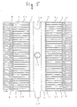
- Fig. 6 is a top view showing an embodiment of the invention when a recording head is formed using two actuator units;
- Figs. 7(a) and 7(b) are sectional views showing how nozzle openings and pressure generating chambers are connected around where the actuator units are connected to each other;
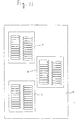
- Fig. 8 is a sectional view showing a laminated ink jet recording head according to the invention the recording head being formed using three actuator units;
- Fig. 9 is a sectional view showing pressure generating chambers and related portions thereof in one actuator unit in another embodiment of the ink jet print head of the invention;
- Fig. 10 is a sectional view showing pressure generating chambers and related portions thereof in one actuator unit in still another embodiment of the ink jet print head of the invention; and
- Fig. 11 is a diagram showing an example of a laminated ink jet recording head.
-
- Figs. 1 and 2 show an actuator unit for use in an ink jet recording head according to the invention. In Figs. 1 and 2,
reference numeral 1 denotes a first cover plate, which comprises a thin zirconia plate having a thickness of about 9 µm and has driveelectrodes 3, 3' formed on a surface thereof in such a manner that thedrive electrodes 3, 3' confrontpressure generating chambers 2, 2' that will be described later.Piezoelectric vibrators 4, 4' made of PZT or the like are deposited on thedrive electrodes 3, 3'. -
Reference numeral 5 denotes a spacer that defines thepressure generating chambers 2, 2'. Thespacer 5 has through holes that will serve as thepressure generating chambers 2, 2' in such a manner that the through holes are arranged at a pitch equal to or less than a pitch P2. The pitch P2 is a pitch at which nozzle openings 30, 30' of aflow path unit 20, which will be described later, are arranged. Thespacer 5 is also designed so that a width W3 of a partition wall 5c that defines onepressure generating chamber 2 from another pressure generating chamber 2' will become about 1/3 the width of each of thepressure generating chambers 2, 2'. -
Reference numeral 6 denotes a second cover body. On sides of thesecond cover body 6 toward which thepressure generating chambers 2, 2' confront each other are inkjetting outlets 7, 7' and on the sides thereof opposite to such sides are ink flowinginlets 8, 8'. Theink jetting outlets 7, 7' and theink flowing inlets 8, 8' are formed so as to communicate with thepressure generating chambers 2, 2'. - By the way,
partition walls 5a, 5b positioned on both outermost ends of thespacer 5 as well as partition walls 6a, 6b on both outermost ends of the second cover body 6'are adequately rigid even if widths W1, W2 thereof are set to a value substantially equal to the width W3 of the partition wall 5c of thespacer 5 and of a partition wall 6c of thesecond cover body 6 that are formed inside. Therefore, the widths W1, W2 are set to values substantially equal to or more than the width W3 of the partition wall 5c of thepressure generating chamber 2 and substantially equal to or less than 1/2 a pitch P1 at which thepressure generating chambers 2 are arranged. Hereupon, the width W1 may be equal to the width W2 or W1 is less or more than the W2. - These
members actuator unit 10 by molding a clay-like ceramic material into predetermined shapes and laminating and sintering the molded shapes without using an adhesive. - The
actuator unit 10 has a positioning throughholes 11 and a positioning through recess in the middle in order to facilitate the assembling operation. - When the
spacer 5 that needs suchthin partition walls 5a, 5b, 5c is to be formed of agreen sheet 12 made of ceramic material, agroove 13 that extends as far as cutting lines C, C is formed along a boundary region so as to match the forming of the through holes serving as thepressure generating chambers 2 as shown in Fig. 3. - Upon completion of sintering after drying the
green sheet 12, the both end portions of the sinteredsheet 12 are cut away along the cutting lines C which traverse both ends of thegroove 13, so that the widths W1, W2 of thepartition walls 5a, 5b of thepressure generating chambers 2, 2' positioned toward both outermost ends can be formed with the same accuracy as that of the width W3 of the partition wall 5c that defines thepressure generating chambers 2. - It may be noted that by forming a projection 15 so as to coincide with the positioning through
recess 14 on the other end as shown in Fig. 4 so that an actuator unit having thethrough recess 14 and the projection 15 can be prepared as shown in Fig. 5. The thus constructed actuator unit is advantageous in allowing two actuator units to be positioned relative to each other with ease when each actuator unit is to be set in a flow path unit. - As shown in Figs. 6, 7(a) and 7(b), the
flow path unit 20 is fixed to the thus constructed twoactuator units 10, 10' by bringingoutermost side walls flow path unit 20 and twoactuator units 10, 10' withfixing members fixing members contact line 18. As a result, a recording head having the twoactuator units 10, 10' arranged on a straight line in tandem can be completed. - In this case, as shown in Figs. 7(a) and (b), the
partition walls 5b, 5a of therespective actuator units 10, 10' confront one another at portions where the two adjacent pressure generating chambers 2a, 2b that are in contact with thecontact line 18 are partitioned, thecontact line 18 being a line with which the twoactuator units 10, 10' come into contact. Therefore, thepartition walls 5b, 5a are about twice as thick as each partition wall 5c that partitions otherpressure generating chambers 2. - However, by slightly shifting
nozzle communication holes flow path unit 20 toward thenozzle openings 30, thesepressure generating chambers nozzle openings 30, 30' that are arranged at the predetermined pitch P2. - The
flow path unit 20 to which theseactuator units 10, 10' are fixed is formed by laminating an ink supplyinlet forming substrate 21, a common inkchamber forming substrate 22, and anozzle plate 23 withadhesive layers -
Ink supply inlets 27, 27' that not only connectcommon ink chambers 26, 26' to thepressure generating chambers 2, 2' but also serve as constrictions that utilize pressure effectively, are formed in the ink supplyinlet forming substrate 21. Thenozzle communication holes 28, 28' that introduce ink from thepressure generating chambers 2, 2' into thenozzle openings 20, 20' are also formed in the ink supplyinlet forming substrate 21. - Further, the common ink
chamber forming substrate 22 is prepared by forming thecommon ink chambers 26, 26' andnozzle communication holes 29, 29'. Thecommon ink chambers 26, 26' receive the ink from a not shown ink tank and distribute, the received ink to the respectivepressure generating chambers 2, 2'. Thenozzle communication holes 29, 29' connect thepressure generating chambers 2, 2' to thenozzle openings - The
nozzle plate 23 is prepared by forming thenozzle openings 30, 30' so as to be arranged on a single line at the predetermined pitch P2. - As described above, the distance between the two pressure generating chambers 2a, 2b located at the boundary at which the two
actuator units 10, 10' are connected to each other is substantially twice the width of the partition wall 5c that defines the respectivepressure generating chambers partition wall 5b. That is, a distance P3 between the pressure generating chambers 2a, 2b is larger than the distance P1 between otherpressure generating chambers - However, by forming the
nozzle communication holes 28, 28' of the ink supplyinlet forming substrate 21 and thenozzle communication holes 29, 29' of the common inkchamber forming substrate 22 so as to shift slightly toward thecontact line 18, these pressure generating chambers 2a, 2b can be connected to each other without causing ink droplets to be jetted out into thenozzle openings nozzle openings - Specifically, if the
pressure generating chambers 2, 2' are arranged at a pitch P1 of about 0.03 cm (about 4/360 inches), then the width W3 of the partition wall 5c defining thepressure generating chambers 2 can be set to about 0.007 cm (about 1/360 inches) and this allows the distance P3 between the two pressure generating chambers 2a, 2b interposing thecontact line 18 therebetween to be set to about 0.04 cm (about 6/360 inches). That is, the distance P3 becomes wider merely by about 0.014 cm (about 2/360 inches) than the pitch P1 of thepressure generating chambers 2, 2' other than the outermost pressure generating chambers. - If the nozzle communication holes 28, 28' of the ink supply
inlet forming substrate 21 and the nozzle communication holes 29, 29' of the common inkchamber forming substrate 22 of theflow path unit 20 are arranged so as to position toward thecontact line 18, the ink can be driven out of thenozzle openings 30 smoothly without stagnation in thepressure generating chambers 2, 2' since steps between the upper and lower communication holes 28, 29, 28', 29' are reduced. - As a result, a plurality of
actuator units 10 can be arranged in tandem on a straight line with respect to thenozzle openings nozzle openings - While the case where the recording head is constructed by connecting two actuator units in tandem has been described in the aforementioned embodiment, a recording head may be constructed by connecting three or
more actuator units flow path unit 20 having nozzle openings at the predetermined pitch P2 by making the pitch P1 at which the pressure generating chambers are arranged slightly smaller than the pitch P2 at which thenozzle openings 30 formed in theflow path unit 20 are arranged as shown in Fig. 8. - That is, assuming that the nozzle arrangement pitch is P2, that the distance between the ends of the adjacent actuator units is P3, and that the number of pressure generating chambers in a single row of a single actuator unit is N, then the pressure generating chamber arrangement pitch P1 may be set as follows.
- The pressure generating chambers in the middle of the
actuator units pressure generating chambers 41, 42 of the actuator unit 10' in the middle are positioned on vertical lines ofnozzle openings pressure generating chambers 41, 42 are to be connected, whereas thepressure generating chambers nozzle openings pressure generating chambers - However, if the nozzle opening arrangement pitch P2 is set to 0.03 cm (4/360 inch) as described above and the number of nozzle openings in a row to which the
actuator units pressure generating chamber 2, 2' are arranged is about 4.6 µm. Therefore, if the pitch P4 at which the nozzle communication holes 28, 28, 28 ·· ·· of the ink supplyinlet forming substrate 21 and a pitch P5 at which the nozzle communication holes 29, 29, 29 ·· ·· of the common inkchamber forming substrate 22 are given aspressure generating chambers 2 to thecorresponding nozzle openings 30. - By making the pressure generating chamber arrangement pitch P1 slightly smaller than the nozzle opening arrangement pitch P2, the pressure generating chambers located in the middles of the
actuator units flow path unit 20 are gradually shifted slightly toward a side end, an increase in the thickness due to the two partition walls 5a', 5b" of the twopressure generating chambers partition walls 5a and 5b' of thepressure generating chambers 50, 57 can be absorbed merely by shifting the positions of the communication holes of the flow path units confronting the actuator units within the ranges of the regions in which the respective actuator units confront. Therefore, four or more actuator units can be connected in tandem. - While the case where a plurality of actuator units are connected in a row has been described in the aforementioned embodiment, it is apparent that an ink jet recording head for a multi-nozzle color printer can be constructed simply by arranging a number of actuator units in tandem in a carriage moving direction.
- In the aforementioned actuator unit, the pressure generating portion comprises the
first cover plate 1, thepiezoelectric vibrators 4 and thedrive electrodes 3 as shown in Figs. 1 and 2. Alternatively, the pressure generating portion which comprises piezoelectric vibrating plates 100,lower electrodes 101 andupper electrodes 102 so as to seal a surface of the space may be applied as shown in Fig. 9. Furthermore, the pressure generating portion comprisingcover plates 106, electricallyconductive layer 103, heating elements 104 andprotective layer 105 may be used as shown in Fig. 10. Other constitutions which make the pressure in the pressure generating chamber change may be used for the present invention. - As described in the foregoing, the invention is characterized in that an actuator unit for a laminated ink jet recording head, a plurality of actuator units being brought into contact with each other at ends thereof and laminated on a flow path unit including nozzle openings, comprising: a first cover member having piezoelectric vibrators on the surface thereof; a spacer for forming pressure generating chambers, one surface thereof being sealed by the first cover member; and a second cover member laminated on the spacer and having ink jetting outlets communicating with one end of the pressure generating chambers and ink flowing inlets communicating with the other end of the pressure generating chambers; wherein a pitch at which the pressure generating chambers are arranged is set equal to or less than a pitch at which the nozzle openings are arranged and the width of partition walls on an outermost ends of the pressure generating chambers located at the
- Furthermore, there is provided an actuator unit (10) for an ink jet recording head comprising: a plurality of pressure generating chambers (2, 2') communicating respectively with nozzle openings (30, 30'); and pressure generating means for pressurizing respectively said plurality of pressure generating chambers (2, 2'); wherein a pitch at which said pressure generating chambers (2, 2') are arranged is set equal to or less than a pitch at which said nozzle openings (30, 30') are arranged, and the width of partition walls (5a, 5b) on the outermost ends of said pressure generating chambers (2, 2') located at the outermost ends of said actuator (10) is set equal to or more than a width of a partition wall (5c) defining adjacent pressure generating chambers (2, 2') and equal to or less than 1/2 the nozzle opening arrangement pitch. Within an ink jet recording head a plurality of actuator units (10, 10', 10") are preferaybly brought into contact with each other at ends thereof and laminated on a flow path unit (20) includin gnozzle openings (30, 30'). Such an actuator unit for an ink jet recording head preferably further comprises: a first cover member (1) having piezoelectric vibrators (4, 4') on the surface thereof; a spacer (5) for forming said pressure generating chambers (2, 2'), one surface thereof being sealed by said first cover member (1); and a second cover member (6) laminated on said spacer (5) and having ink jetting outlets (7, 7') communicating with one end of said pressure generating chambers (2, 2') and ink flowing inlets (8, 8') communicating with the other end of said pressure generating chambers (2, 2').
- Preferably the pressure generating chamber arrangement pitch P1 is given as follows:
- Preferably the pressure generating chamber arrangement pitch is set substantially equal to 0.03 cm (4/360 inches) and the width of the partition defining the pressure generating chambers is set substantially equal to about 0.007 cm (about 1/360 inches).
- Preferably a positioning through recess (14) is formed on one end in a pressure generating chamber arrangement direction.
- Preferably a positioning through recess (14) is arranged on one end in a pressure generating chamber arrangement direction and a projection (15) engageable with said through recess (14) is formed on the other end.
- Furthermore, there is provided a method of fabricating an actuator unit according to one of
claims 1 to 7 for an ink jet recording head according to one ofclaims 8 to 12 comprising the steps of: forming cutting lines on both ends of a green sheet made of ceramic; forming through holes serving as pressure generating chambers of the actuator unit in the green sheet; forming a groove in a boundary region to separate a plurality of spacers of the actuator unit, wherein the groove extends as far as the cutting lines and vertically to the arrangement direction of the through holes and have a width such that the width of partition walls on outermost ends of the pressure generating chambers located at the outermost ends of the actuator unit can be set; sintering the green sheet; and cutting away both end portions of the green sheet from the cutting line.
Claims (6)
- An ink jet recording head using a plurality of actuator units, each of said actuator units (10, 10', 10") comprising:a plurality of pressure generating chambers (2, 2') communicating respectively with said nozzle openings (30, 30'); andpressure generating means for pressurizing respectively said plurality of pressure generating chambers (2, 2'); andsaid ink jet recording head further comprising:a flow path unit (20) including nozzle openings (30, 30') communicating with said pressure generating chambers (2, 2');wherein a plurality of said actuator units (10, 10', 10") are brought into contact with each other at ends thereof so that said actuator units (10, 10', 10") are arranged straight in an arrangement direction of said pressure generating chamber (2, 2') on said flow path unit (20),characterized in thata pitch P1 at which said pressure generating chambers (2, 2') are arranged is set equal to or less than a pitch P2 at which nozzle openings (30, 30') are arranged, and the width (W1, W2) of partition walls (5a, 5b) on the outermost ends of said pressure generating chambers (2, 2') located at the outermost ends of said actuator unit (10, 10', 10") is set equal to or more than a width (W3) of a partition wall (5c) defining adjacent pressure generating chambers (2, 2') and equal to or less than 1/2 the nozzle opening arrangement pitch.
- The ink jet recording head according to claim 1, wherein said flow path unit (20) includes a common ink chamber (26, 26') that is provided for said plurality of actuator units (10, 10', 10").
- The ink jet recording head according to claim 1 or 2, further comprising:a first cover member (1) having piezoelectric vibrators (4) on the surface thereof;a spacer (5) for forming pressure generating chambers (2, 2'), one surface thereof being sealed by said first cover member (1); anda second cover member (6) laminated on said spacer (5) and having ink jetting outlets (7, 7') communicating with one end of said pressure generating chambers (2, 2'); and ink flowing inlets (8, 8') communicating with the other end of said pressure generating chambers (2, 2').
- The ink jet recording head according to one of claims 1 to 3, wherein said flow path unit (20) comprises:an ink supply inlet forming substrate (21) for forming ink supply inlets (27, 27') communicating with said ink flowing inlets (8, 8') and first nozzle communication holes (28, 28') communication with said ink jetting outlets (7, 7');a common ink chamber forming substrate (22) for forming said common ink chamber (26, 26'); andsecond nozzle communication holes (29, 29') communicating with said first nozzle communication holes (28, 28'); anda nozzle plate (23) for forming said nozzle openings (30, 30').
- The ink jet recording head according to one of claims 1 to 4, wherein the pressure generating chamber arrangement pitch P1 is given as follows:
- The ink jet recording head according to one of claims 1 to 5, wherein a fixing member (17) is arranged so as to mount over a contact surface between said actuator units (10, 10', 10").
Applications Claiming Priority (3)
| Application Number | Priority Date | Filing Date | Title |
|---|---|---|---|
| JP20839795 | 1995-07-24 | ||
| JP20839795 | 1995-07-24 | ||
| EP96111942A EP0755791B1 (en) | 1995-07-24 | 1996-07-24 | Actuator unit for an ink jet recording head and method of fabricating same |
Related Parent Applications (1)
| Application Number | Title | Priority Date | Filing Date |
|---|---|---|---|
| EP96111942A Division EP0755791B1 (en) | 1995-07-24 | 1996-07-24 | Actuator unit for an ink jet recording head and method of fabricating same |
Publications (2)
| Publication Number | Publication Date |
|---|---|
| EP1034930A1 true EP1034930A1 (en) | 2000-09-13 |
| EP1034930B1 EP1034930B1 (en) | 2003-06-11 |
Family
ID=16555584
Family Applications (2)
| Application Number | Title | Priority Date | Filing Date |
|---|---|---|---|
| EP96111942A Expired - Lifetime EP0755791B1 (en) | 1995-07-24 | 1996-07-24 | Actuator unit for an ink jet recording head and method of fabricating same |
| EP00112087A Expired - Lifetime EP1034930B1 (en) | 1995-07-24 | 1996-07-24 | Ink jet recording head |
Family Applications Before (1)
| Application Number | Title | Priority Date | Filing Date |
|---|---|---|---|
| EP96111942A Expired - Lifetime EP0755791B1 (en) | 1995-07-24 | 1996-07-24 | Actuator unit for an ink jet recording head and method of fabricating same |
Country Status (4)
| Country | Link |
|---|---|
| US (1) | US5907340A (en) |
| EP (2) | EP0755791B1 (en) |
| DE (2) | DE69613636T2 (en) |
| HK (1) | HK1011323A1 (en) |
Families Citing this family (18)
| Publication number | Priority date | Publication date | Assignee | Title |
|---|---|---|---|---|
| JP3473675B2 (en) * | 1997-01-24 | 2003-12-08 | セイコーエプソン株式会社 | Ink jet recording head |
| EP0921003A1 (en) * | 1997-12-03 | 1999-06-09 | Océ-Technologies B.V. | Ink-jet array printhead |
| EP0963846B1 (en) * | 1998-06-08 | 2005-08-31 | Seiko Epson Corporation | Ink jet recording head and ink jet recording apparatus |
| JP4403353B2 (en) * | 2000-02-18 | 2010-01-27 | 富士フイルム株式会社 | Inkjet recording head manufacturing method and printer apparatus |
| US6862806B2 (en) * | 2000-10-17 | 2005-03-08 | Brother Kogyo Kabushiki Kaisha | Method for fabricating an ink-jet printer head |
| JP2002254649A (en) | 2001-03-06 | 2002-09-11 | Sony Corp | Printer head, printer, and driving method for printer head |
| JP2004001338A (en) | 2001-12-27 | 2004-01-08 | Seiko Epson Corp | Liquid ejection head and its manufacturing method |
| US6994428B2 (en) | 2002-05-21 | 2006-02-07 | Brother Kogyo Kabushiki Kaisha | Ink-jet printing head having a plurality of actuator units and/or a plurality of manifold chambers |
| US7052117B2 (en) | 2002-07-03 | 2006-05-30 | Dimatix, Inc. | Printhead having a thin pre-fired piezoelectric layer |
| US8491076B2 (en) | 2004-03-15 | 2013-07-23 | Fujifilm Dimatix, Inc. | Fluid droplet ejection devices and methods |
| US7281778B2 (en) | 2004-03-15 | 2007-10-16 | Fujifilm Dimatix, Inc. | High frequency droplet ejection device and method |
| JP2006175845A (en) * | 2004-11-29 | 2006-07-06 | Ricoh Co Ltd | Liquid discharge head, liquid discharge apparatus, and image forming apparatus |
| KR20070087223A (en) | 2004-12-30 | 2007-08-27 | 후지필름 디마틱스, 인크. | Ink jet printing |
| KR100738102B1 (en) * | 2006-02-01 | 2007-07-12 | 삼성전자주식회사 | Piezoelectric inkjet printhead |
| ATE548193T1 (en) * | 2006-04-07 | 2012-03-15 | Oce Tech Bv | INKJET PRINTHEAD |
| US7988247B2 (en) | 2007-01-11 | 2011-08-02 | Fujifilm Dimatix, Inc. | Ejection of drops having variable drop size from an ink jet printer |
| JP4944687B2 (en) * | 2007-06-28 | 2012-06-06 | 株式会社リコー | Piezoelectric actuator and manufacturing method thereof, liquid ejection head, and image forming apparatus |
| US9844941B2 (en) * | 2016-02-26 | 2017-12-19 | Seiko Epson Corporation | Liquid ejecting head and liquid ejecting apparatus |
Citations (8)
| Publication number | Priority date | Publication date | Assignee | Title |
|---|---|---|---|---|
| US4730196A (en) * | 1985-07-01 | 1988-03-08 | U.S. Philips Corporation | Ink-jet printer |
| US4937597A (en) * | 1988-02-16 | 1990-06-26 | Fuji Electric Co., Ltd. | Ink jet printing head |
| JPH05261918A (en) * | 1992-03-18 | 1993-10-12 | Seiko Epson Corp | Ink jet head |
| EP0572230A2 (en) * | 1992-05-27 | 1993-12-01 | Ngk Insulators, Ltd. | Piezoelectric/electrostrictive actuator having integral ceramic base member and film-type piezoelectric/electrostrictive element(s) |
| EP0584823A1 (en) * | 1992-08-26 | 1994-03-02 | Seiko Epson Corporation | Ink jet recording head and manufacturing method therefor |
| EP0600743A2 (en) * | 1992-12-04 | 1994-06-08 | Ngk Insulators, Ltd. | Actuator having ceramic substrate and ink jet print head using the actuator |
| EP0648607A2 (en) * | 1993-10-19 | 1995-04-19 | Francotyp-Postalia GmbH | Face shooter thermal ink-jet printhead and method for manufacturing it |
| EP0659562A2 (en) * | 1993-12-24 | 1995-06-28 | Seiko Epson Corporation | Laminated ink jet recording head |
Family Cites Families (1)
| Publication number | Priority date | Publication date | Assignee | Title |
|---|---|---|---|---|
| JPS6119367A (en) * | 1984-07-05 | 1986-01-28 | Canon Inc | Liquid injection recording head |
-
1996
- 1996-07-23 US US08/681,376 patent/US5907340A/en not_active Expired - Lifetime
- 1996-07-24 EP EP96111942A patent/EP0755791B1/en not_active Expired - Lifetime
- 1996-07-24 DE DE69613636T patent/DE69613636T2/en not_active Expired - Lifetime
- 1996-07-24 EP EP00112087A patent/EP1034930B1/en not_active Expired - Lifetime
- 1996-07-24 DE DE69628680T patent/DE69628680T2/en not_active Expired - Lifetime
-
1998
- 1998-11-26 HK HK98112349A patent/HK1011323A1/en not_active IP Right Cessation
Patent Citations (9)
| Publication number | Priority date | Publication date | Assignee | Title |
|---|---|---|---|---|
| US4730196A (en) * | 1985-07-01 | 1988-03-08 | U.S. Philips Corporation | Ink-jet printer |
| US4937597A (en) * | 1988-02-16 | 1990-06-26 | Fuji Electric Co., Ltd. | Ink jet printing head |
| JPH05261918A (en) * | 1992-03-18 | 1993-10-12 | Seiko Epson Corp | Ink jet head |
| EP0572230A2 (en) * | 1992-05-27 | 1993-12-01 | Ngk Insulators, Ltd. | Piezoelectric/electrostrictive actuator having integral ceramic base member and film-type piezoelectric/electrostrictive element(s) |
| JPH0640035A (en) | 1992-05-27 | 1994-02-15 | Ngk Insulators Ltd | Piezoelectric/electrostrictive actuator |
| EP0584823A1 (en) * | 1992-08-26 | 1994-03-02 | Seiko Epson Corporation | Ink jet recording head and manufacturing method therefor |
| EP0600743A2 (en) * | 1992-12-04 | 1994-06-08 | Ngk Insulators, Ltd. | Actuator having ceramic substrate and ink jet print head using the actuator |
| EP0648607A2 (en) * | 1993-10-19 | 1995-04-19 | Francotyp-Postalia GmbH | Face shooter thermal ink-jet printhead and method for manufacturing it |
| EP0659562A2 (en) * | 1993-12-24 | 1995-06-28 | Seiko Epson Corporation | Laminated ink jet recording head |
Non-Patent Citations (1)
| Title |
|---|
| PATENT ABSTRACTS OF JAPAN vol. 18, no. 25 (M - 1542) 14 January 1994 (1994-01-14) * |
Also Published As
| Publication number | Publication date |
|---|---|
| DE69628680D1 (en) | 2003-07-17 |
| DE69628680T2 (en) | 2003-12-18 |
| US5907340A (en) | 1999-05-25 |
| EP0755791A2 (en) | 1997-01-29 |
| EP0755791A3 (en) | 1997-11-05 |
| EP1034930B1 (en) | 2003-06-11 |
| DE69613636T2 (en) | 2002-05-08 |
| DE69613636D1 (en) | 2001-08-09 |
| HK1011323A1 (en) | 1999-07-09 |
| EP0755791B1 (en) | 2001-07-04 |
Similar Documents
| Publication | Publication Date | Title |
|---|---|---|
| US11305536B2 (en) | Ink-jet head having passage unit and actuator units attached to the passage unit, and ink-jet printer having the ink-jet head | |
| EP0755791B1 (en) | Actuator unit for an ink jet recording head and method of fabricating same | |
| EP1034931B1 (en) | Ink jet type recording head | |
| US6945636B2 (en) | Ink-jet head, method for manufacturing ink-jet head and ink-jet printer having ink-jet head | |
| US7712885B2 (en) | Liquid-droplet jetting apparatus | |
| EP1510343B1 (en) | Ink-jet head and ink-jet printer | |
| JP4324757B2 (en) | Inkjet printer head | |
| EP0950525A2 (en) | Ink jet recording head | |
| JP6641023B2 (en) | Liquid ejection head and recording device | |
| EP1806228B1 (en) | Ink-jet head | |
| EP0985536B1 (en) | Ink jet type recording head | |
| JP3525978B2 (en) | Laminated ink jet recording head and method of manufacturing actuator unit thereof | |
| US6874869B1 (en) | Inkjet printhead | |
| JP6641022B2 (en) | Liquid ejection head and recording device | |
| JP3925648B2 (en) | Inkjet printer head |
Legal Events
| Date | Code | Title | Description |
|---|---|---|---|
| PUAI | Public reference made under article 153(3) epc to a published international application that has entered the european phase |
Free format text: ORIGINAL CODE: 0009012 |
|
| 17P | Request for examination filed |
Effective date: 20000605 |
|
| AC | Divisional application: reference to earlier application |
Ref document number: 755791 Country of ref document: EP |
|
| AK | Designated contracting states |
Kind code of ref document: A1 Designated state(s): DE FR GB IT |
|
| AKX | Designation fees paid |
Free format text: DE FR GB IT |
|
| GRAG | Despatch of communication of intention to grant |
Free format text: ORIGINAL CODE: EPIDOS AGRA |
|
| 17Q | First examination report despatched |
Effective date: 20020618 |
|
| GRAG | Despatch of communication of intention to grant |
Free format text: ORIGINAL CODE: EPIDOS AGRA |
|
| GRAG | Despatch of communication of intention to grant |
Free format text: ORIGINAL CODE: EPIDOS AGRA |
|
| GRAH | Despatch of communication of intention to grant a patent |
Free format text: ORIGINAL CODE: EPIDOS IGRA |
|
| GRAH | Despatch of communication of intention to grant a patent |
Free format text: ORIGINAL CODE: EPIDOS IGRA |
|
| GRAA | (expected) grant |
Free format text: ORIGINAL CODE: 0009210 |
|
| AC | Divisional application: reference to earlier application |
Ref document number: 0755791 Country of ref document: EP Kind code of ref document: P |
|
| AK | Designated contracting states |
Designated state(s): DE FR GB IT |
|
| REG | Reference to a national code |
Ref country code: GB Ref legal event code: FG4D |
|
| REF | Corresponds to: |
Ref document number: 69628680 Country of ref document: DE Date of ref document: 20030717 Kind code of ref document: P |
|
| ET | Fr: translation filed | ||
| PLBE | No opposition filed within time limit |
Free format text: ORIGINAL CODE: 0009261 |
|
| STAA | Information on the status of an ep patent application or granted ep patent |
Free format text: STATUS: NO OPPOSITION FILED WITHIN TIME LIMIT |
|
| 26N | No opposition filed |
Effective date: 20040312 |
|
| PGFP | Annual fee paid to national office [announced via postgrant information from national office to epo] |
Ref country code: DE Payment date: 20140716 Year of fee payment: 19 |
|
| PGFP | Annual fee paid to national office [announced via postgrant information from national office to epo] |
Ref country code: GB Payment date: 20140723 Year of fee payment: 19 Ref country code: FR Payment date: 20140708 Year of fee payment: 19 |
|
| PGFP | Annual fee paid to national office [announced via postgrant information from national office to epo] |
Ref country code: IT Payment date: 20140715 Year of fee payment: 19 |
|
| REG | Reference to a national code |
Ref country code: DE Ref legal event code: R119 Ref document number: 69628680 Country of ref document: DE |
|
| GBPC | Gb: european patent ceased through non-payment of renewal fee |
Effective date: 20150724 |
|
| PG25 | Lapsed in a contracting state [announced via postgrant information from national office to epo] |
Ref country code: DE Free format text: LAPSE BECAUSE OF NON-PAYMENT OF DUE FEES Effective date: 20160202 Ref country code: IT Free format text: LAPSE BECAUSE OF NON-PAYMENT OF DUE FEES Effective date: 20150724 Ref country code: GB Free format text: LAPSE BECAUSE OF NON-PAYMENT OF DUE FEES Effective date: 20150724 |
|
| REG | Reference to a national code |
Ref country code: FR Ref legal event code: ST Effective date: 20160331 |
|
| PG25 | Lapsed in a contracting state [announced via postgrant information from national office to epo] |
Ref country code: FR Free format text: LAPSE BECAUSE OF NON-PAYMENT OF DUE FEES Effective date: 20150731 |