EP1039628A1 - Highly integrated radio frequency transmitter with image rejection, optionally auto-calibrated - Google Patents
Highly integrated radio frequency transmitter with image rejection, optionally auto-calibrated Download PDFInfo
- Publication number
- EP1039628A1 EP1039628A1 EP00460019A EP00460019A EP1039628A1 EP 1039628 A1 EP1039628 A1 EP 1039628A1 EP 00460019 A EP00460019 A EP 00460019A EP 00460019 A EP00460019 A EP 00460019A EP 1039628 A1 EP1039628 A1 EP 1039628A1
- Authority
- EP
- European Patent Office
- Prior art keywords
- frequency
- digital
- signal
- transmitter according
- quadrature
- Prior art date
- Legal status (The legal status is an assumption and is not a legal conclusion. Google has not performed a legal analysis and makes no representation as to the accuracy of the status listed.)
- Granted
Links
Images

Classifications
-
- H—ELECTRICITY
- H04—ELECTRIC COMMUNICATION TECHNIQUE
- H04L—TRANSMISSION OF DIGITAL INFORMATION, e.g. TELEGRAPHIC COMMUNICATION
- H04L27/00—Modulated-carrier systems
- H04L27/18—Phase-modulated carrier systems, i.e. using phase-shift keying
- H04L27/20—Modulator circuits; Transmitter circuits
- H04L27/2032—Modulator circuits; Transmitter circuits for discrete phase modulation, e.g. in which the phase of the carrier is modulated in a nominally instantaneous manner
- H04L27/2053—Modulator circuits; Transmitter circuits for discrete phase modulation, e.g. in which the phase of the carrier is modulated in a nominally instantaneous manner using more than one carrier, e.g. carriers with different phases
- H04L27/206—Modulator circuits; Transmitter circuits for discrete phase modulation, e.g. in which the phase of the carrier is modulated in a nominally instantaneous manner using more than one carrier, e.g. carriers with different phases using a pair of orthogonal carriers, e.g. quadrature carriers
-
- H—ELECTRICITY
- H03—ELECTRONIC CIRCUITRY
- H03C—MODULATION
- H03C3/00—Angle modulation
- H03C3/38—Angle modulation by converting amplitude modulation to angle modulation
- H03C3/40—Angle modulation by converting amplitude modulation to angle modulation using two signal paths the outputs of which have a predetermined phase difference and at least one output being amplitude-modulated
- H03C3/403—Angle modulation by converting amplitude modulation to angle modulation using two signal paths the outputs of which have a predetermined phase difference and at least one output being amplitude-modulated using two quadrature frequency conversion stages in cascade
-
- H—ELECTRICITY
- H03—ELECTRONIC CIRCUITRY
- H03D—DEMODULATION OR TRANSFERENCE OF MODULATION FROM ONE CARRIER TO ANOTHER
- H03D7/00—Transference of modulation from one carrier to another, e.g. frequency-changing
- H03D7/16—Multiple-frequency-changing
- H03D7/165—Multiple-frequency-changing at least two frequency changers being located in different paths, e.g. in two paths with carriers in quadrature
- H03D7/166—Multiple-frequency-changing at least two frequency changers being located in different paths, e.g. in two paths with carriers in quadrature using two or more quadrature frequency translation stages
Definitions
- the field of the invention is that of signal transmission by channel over the air.
- the invention relates to a radiofrequency transmitter of the type supplied by two signals (or components) in baseband and quadrature, i (t) and q (t), which are images of two bit streams representing a information to be transmitted.
- i (t) and q (t) are images of two bit streams representing a information to be transmitted.
- the radiofrequency transmitter with frequency transposition which allows transposition to an IF intermediate frequency, requires the use of filters selective bandpass, in order to reject the image frequency to that of the useful signal at issue.
- This first type of radiofrequency transmitter offers good performance, thanks to frequency transposition in the field digital.
- the need to use high-performance filters limits its degree of integration on silicon.
- the direct conversion radio frequency transmitter presents the architecture simpler and offers a high level of integration. Its weak point is its great sensitivity to the performance of the elements that make it up. In particular, it avoid leaking the local oscillator through the mixer, or ensure perfect quadrature of the sine and cosine signals. Now, these imperatives are often difficult to meet.
- the phase locked loop radiofrequency transmitter has many advantages, including the freedom from RF filters thanks to the bandpass characteristic of the phase locked loop (or PLL, for "Phase Lock Loop” in English). The need to have signals strictly in squaring is also avoided. However, these results are only possible if the voltage controlled oscillator (or VCO, for "Voltage Controlled Oscillator” in English) included in the PLL has high performance. However, this is not not yet the case of integrated VCOs. Therefore, the radio frequency transmitter PLL does not offer a high level of integration.
- the invention particularly aims to overcome these different disadvantages of the state of the art.
- one of the objectives of the present invention is to provide a radiofrequency transmitter with good precision and very strong degree of integration on silicon.
- the invention also aims to provide such a transmitter radio frequency with very low sensitivity to imperfections in elements that compose it.
- Another object of the invention is to provide such a transmitter radio frequency to avoid degradation of the useful signal.
- An additional objective of the invention is to provide such a transmitter radio frequency which is simple and has a small excess of complexity by compared to known architectures.
- the invention also aims to provide such a transmitter radio frequency to generate a resulting signal having a frequency image weak enough to be deleted with an aux filter constraints relaxed (this filter can therefore possibly be integrated).
- the invention also aims to provide such a radiofrequency transmitter having no image frequency, the output image frequency being completely attenuated, automatically, thanks to a self-calibration system and compensation for gain imperfections and in phase.
- the present invention therefore proposes an original transmitter architecture radiofrequency, combining architectures with direct conversion and frequency transposition, and also providing for processing means digital, which provide a pre-processing to attenuate, at output image frequency introduced by the frequency transposition means intermediate.
- this new architecture combines the main advantage of the direct conversion radiofrequency transmitter (no image frequency) with that of the radio frequency transmitter with frequency transposition (no degradation of the useful signal), while avoiding their disadvantages (sensitivity to imperfections, powerful image filter).
- the first frequency transposition and the processing of signal are carried out in the digital domain, which makes it possible to exploit the precision and the high degree of integration (on silicon for example).
- the radiofrequency transmitter according to the invention has a very high degree of integration (for example on silicon), and can even advantageously be produced entirely in the form of an integrated circuit.
- the means of direct conversion are known for their high degree of integration silicon.
- the level of integration of the means of transposition into intermediate frequency can be relatively high since it is not necessary use effective filters.
- digital processing resources can be summarized as a set of elements commonly used in integrated systems on silicon, and in particular in transposition transmitters frequency. This set of elements includes for example an oscillator digitally controlled (or NCO for "Numerically Controlled Oscillator) and linear operators (multipliers and adders).
- said transmitter radio frequency further comprises means for digital compensation of imperfections in gain and phase of said direct conversion means.
- radiofrequency transmitter therefore operates independently of the carrier frequency chosen and is therefore particularly suitable for multistandard radiocommunication systems.
- GSM Global System for Mobile communications
- DCS 1800 for “Digital Cellular System 1800 MHz” in English
- PCS 1900 for “Personal Communication System” in English
- DECT for "Digital European Cordless Telecommunications” in English
- UMTS for "Universal Mobile Telecommunication System” in English
- said analog / digital conversion means have a working frequency substantially identical to the working frequency of digital / analog conversion means included in said direct conversion means.
- said digital compensation means are included in said integrated circuit.
- the radiofrequency transmitter according to the present invention can be fully integrated, for example on silicon.
- the invention therefore relates to a radiofrequency transmitter of the powered type.
- i (nT) and q (nT) which are images of two bit streams representing information to transmit.
- T is the sampling period.
- the radiofrequency transmitter comprises means 1 for transposition into intermediate frequency and digital processing and means 2 for direct conversion.
- This filter 17 can possibly also be included in the integrated circuit in the form of which the radiofrequency transmitter is made.
- the principle therefore consists in generating two signals m 1 (t) and m 2 (t) composed of the two quadrature channels i (t) and q (t).
- the direct conversion means 2 transpose the two signals around the carrier frequency ⁇ 1 by multiplying them by sin ( ⁇ 1 t + ⁇ ) and cos ( ⁇ 1 t + ⁇ ).
- m (t) i (t) .cos ( ⁇ 2 t + ⁇ ) - q (t) .sin ( ⁇ 2 t + ⁇ )
- m (t) g 1 .m 1 (t) .cos ( ⁇ 1 t + ⁇ 1 ) + g 2 .m 2 (t) .sin ( ⁇ 1 t + ⁇ 2 )
- Equation (2) makes it possible to write equation (5) by making i (t) and q (t) appear:
- Equation (11) shows that the gain and phase imperfections generate a parasitic component in ⁇ -2 of sufficiently low power to be easily filtered. On the other hand, they have very little influence on the quality of the useful signal.
- the C / I of the useful signal (signal power / disturbance power at frequency ⁇ 2 ) is 68 dBc , instead of 28 dBc for a classic direct conversion architecture.
- the power level of the disturber present at the image frequency ⁇ -2 is approximately 28 dB below the useful signal whereas it would be 25 times higher with a structure with conventional frequency transposition.
- a first intermediate frequency FI ( ⁇ 0 ) generated in the digital domain makes it possible to be able to attenuate the possible leakage of the local oscillator via the mixers.
- This second embodiment differs from the first embodiment (presented above in relation to FIG. 1), in that it further comprises means 10, 11 for digital compensation of imperfections in gain ⁇ g and in phase ⁇ means 2 for direct conversion.
- These compensation means themselves comprise means 10 for estimating the imperfections ⁇ g and ⁇ , and means 11 for applying a correction to the two signals m 1 (t) and m 2 (t), so as to generate two corrected signals, m 1c (t) and m 2c (t).
- the resulting signal m (t) is multiplied by the frequency ⁇ 1 of the local oscillator 7 (the latter is included in the direct conversion means 2).
- ⁇ 1 of the local oscillator 7 the latter is included in the direct conversion means 2.
- m (t) is transposed to a lower, fixed frequency, before analog / digital conversion.
- the low-pass filtering removes the components 2 ⁇ 1 t ⁇ ⁇ 0 t and gives:
- the new corrected emission signal m c (t) must be constructed: where m 1c (t) and m 2c (t) are the two gain and phase corrected channels:
- the algorithms for calculating ⁇ g and ⁇ have been successfully simulated: the error is compensated after 5 iterations at most, according to the orders of magnitude of ⁇ g and ⁇ (up to 10% and 8 ° respectively) and with a error of up to 12% on the value of g 3 .
- the signal processing functions are performed in the digital domain in order to exploit its precision and the high degree of integration on silicon.
- the analog / digital converter (ADC) 14 is for example of the “delta-sigma bandpass” type, the working frequency of which is preferably identical to that of the two DACs 5 1 and 5 2 .
- the analog low-pass filter 13 has relaxed constraints: a filter of order 2 is sufficient in most cases.
- the radio frequency transmitter according to the invention has a complexity relatively low compared to the rest of the broadcast chain and has the advantage of being completely integrable on silicon.
Abstract
Description
Le domaine de l'invention est celui de la transmission de signaux par voie hertzienne.The field of the invention is that of signal transmission by channel over the air.
On rappelle que l'émission d'un signal par voie hertzienne fait de plus en plus souvent appel à la modulation numérique, dont le principal avantage est de permettre l'utilisation d'algorithmes de traitement du signal. Ces derniers ont pour but d'augmenter la robustesse du signal à émettre vis-à-vis du canal de propagation.It is recalled that the emission of a signal by radio means is increasingly most often using digital modulation, the main advantage of which is allow the use of signal processing algorithms. These have for aim of increasing the robustness of the signal to be emitted with respect to the spread.
Plus précisément, l'invention concerne un émetteur radiofréquence du type alimenté par deux signaux (ou composantes) en bande de base et en quadrature, i(t) et q(t), qui sont des images de deux flux binaires représentant une information à transmettre. En effet, quel que soit le type de modulation numérique, le signal à émettre m(t) peut s'écrire : m(t) = i(t).cos(ωt) - q(t).sin(ωt), avec ω (= 2πf) la fréquence d'émission du signal (aussi appelée fréquence porteuse).More specifically, the invention relates to a radiofrequency transmitter of the type supplied by two signals (or components) in baseband and quadrature, i (t) and q (t), which are images of two bit streams representing a information to be transmitted. Indeed, whatever the type of modulation digital, the signal to be transmitted m (t) can be written: m (t) = i (t) .cos (ωt) - q (t) .sin (ωt), with ω (= 2πf) the frequency of emission of the signal (also called frequency carrier).
On connaít, dans l'état de la technique, différents types d'émetteur radiofréquence, basés chacun sur une architecture distincte. Les plus connus sont l'émetteur radiofréquence à transposition de fréquence, l'émetteur radiofréquence à conversion directe et l'émetteur radiofréquence à boucle à verrouillage de phase. Leurs inconvénients respectifs sont maintenant discutés.We know in the prior art, different types of transmitter radiofrequency, each based on a separate architecture. The most famous are the frequency transposition radio frequency transmitter, the radio frequency transmitter with direct conversion and the interlocking loop radiofrequency transmitter phase. Their respective disadvantages are now discussed.
L'émetteur radiofréquence à transposition de fréquence, qui permet une transposition à une fréquence intermédiaire FI, nécessite l'utilisation de filtres passe-bande sélectifs, afin de rejeter la fréquence image à celle du signal utile à émettre. Ce premier type d'émetteur radiofréquence offre de bonnes performances, grâce à une transposition en fréquence dans le domaine numérique. En revanche, la nécessité d'utiliser des filtres performants limite son degré d'intégration sur silicium.The radiofrequency transmitter with frequency transposition, which allows transposition to an IF intermediate frequency, requires the use of filters selective bandpass, in order to reject the image frequency to that of the useful signal at issue. This first type of radiofrequency transmitter offers good performance, thanks to frequency transposition in the field digital. However, the need to use high-performance filters limits its degree of integration on silicon.
L'émetteur radiofréquence à conversion directe présente l'architecture la plus simple et offre un niveau d'intégration élevé. Son point faible est sa grande sensibilité aux performances des éléments qui le composent. Notamment, il convient d'éviter toute fuite de l'oscillateur local via le mélangeur, ou encore d'assurer une parfaite quadrature des signaux en sinus et cosinus. Or, ces impératifs sont souvent difficiles à respecter.The direct conversion radio frequency transmitter presents the architecture simpler and offers a high level of integration. Its weak point is its great sensitivity to the performance of the elements that make it up. In particular, it avoid leaking the local oscillator through the mixer, or ensure perfect quadrature of the sine and cosine signals. Now, these imperatives are often difficult to meet.
L'émetteur radiofréquence à boucle à verrouillage de phase présente de nombreux avantages, dont le fait de s'affranchir de filtres RF grâce à la caractéristique passe-bande de la boucle à verrouillage de phase (ou PLL, pour "Phase Lock Loop" en anglais). La nécessité d'avoir des signaux strictement en quadrature est également évitée. Toutefois, ces résultats ne sont possibles que si l'oscillateur contrôlé en tension (ou VCO, pour "Voltage Controlled Oscillator" en anglais) compris dans la PLL présente des performances élevées. Or, ceci n'est pas encore le cas des VCO intégrés. Par conséquent, l'émetteur radiofréquence à PLL ne permet pas d'offrir un niveau d'intégration élevé.The phase locked loop radiofrequency transmitter has many advantages, including the freedom from RF filters thanks to the bandpass characteristic of the phase locked loop (or PLL, for "Phase Lock Loop" in English). The need to have signals strictly in squaring is also avoided. However, these results are only possible if the voltage controlled oscillator (or VCO, for "Voltage Controlled Oscillator" in English) included in the PLL has high performance. However, this is not not yet the case of integrated VCOs. Therefore, the radio frequency transmitter PLL does not offer a high level of integration.
D'une manière générale, ces trois types d'architecture connus présentent donc un nécessaire compromis entre intégration, consommation et complexité. En d'autres termes, aucune de ces trois solutions connues n'est entièrement satisfaisante.In general, these three known types of architecture have therefore a necessary compromise between integration, consumption and complexity. In other words, none of these three known solutions is entirely satisfactory.
L'invention a notamment pour objectif de pallier ces différents inconvénients de l'état de la technique.The invention particularly aims to overcome these different disadvantages of the state of the art.
Plus précisément, l'un des objectifs de la présente invention est de fournir un émetteur radiofréquence offrant une bonne précision et présentant un très fort degré d'intégration sur silicium.More specifically, one of the objectives of the present invention is to provide a radiofrequency transmitter with good precision and very strong degree of integration on silicon.
L'invention a également pour objectif de fournir un tel émetteur radiofréquence présentant une très faible sensibilité aux imperfections des éléments qui le composent.The invention also aims to provide such a transmitter radio frequency with very low sensitivity to imperfections in elements that compose it.
Un autre objectif de l'invention est de fournir un tel émetteur radiofréquence permettant d'éviter une dégradation du signal utile.Another object of the invention is to provide such a transmitter radio frequency to avoid degradation of the useful signal.
Un objectif complémentaire de l'invention est de fournir un tel émetteur radiofréquence qui soit simple et présente un faible surplus de complexité par rapport aux architectures connues.An additional objective of the invention is to provide such a transmitter radio frequency which is simple and has a small excess of complexity by compared to known architectures.
L'invention a également pour objectif de fournir un tel émetteur radiofréquence permettant de générer un signal résultant présentant une fréquence image suffisamment faible pour pouvoir être supprimée avec un filtre aux contraintes relâchées (ce filtre pouvant donc être éventuellement intégré).The invention also aims to provide such a transmitter radio frequency to generate a resulting signal having a frequency image weak enough to be deleted with an aux filter constraints relaxed (this filter can therefore possibly be integrated).
Dans une variante de réalisation, l'invention a également pour objectif de fournir un tel émetteur radiofréquence ne présentant pas de fréquence image, la fréquence image en sortie étant complètement atténuée, de façon automatique, grâce à un système d'auto-calibrage et de compensation des imperfections en gain et en phase.In an alternative embodiment, the invention also aims to provide such a radiofrequency transmitter having no image frequency, the output image frequency being completely attenuated, automatically, thanks to a self-calibration system and compensation for gain imperfections and in phase.
Ces différents objectifs, ainsi que d'autres qui apparaítront par la suite, sont atteints selon l'invention à l'aide d'un émetteur radiofréquence, du type alimenté par deux signaux en bande de base et en quadrature, i(nT) et q(nT), qui sont des images de deux flux binaires représentant une information à transmettre, l'émetteur radiofréquence comprenant :
- des moyens de transposition en fréquence intermédiaire et de traitement numérique, assurant une première transposition dans le domaine numérique, à une fréquence intermédiaire ω0, desdits signaux en bande de base, et générant, par combinaison, deux signaux à la fréquence intermédiaire et en quadrature ;
- des moyens de conversion directe, assurant une seconde transposition dans le domaine analogique, après multiplication par une fréquence ω1, suivi d'une sommation, desdits deux signaux à la fréquence intermédiaire et en quadrature, de façon à générer un signal résultant qui se trouve au final modulé autour d'une fréquence ω2, avec : ω2 = ω0 + ω1.
- intermediate frequency transposition and digital processing means, ensuring a first transposition in the digital domain, at an intermediate frequency ω 0 , of said baseband signals, and generating, by combination, two signals at the intermediate frequency and in quadrature ;
- direct conversion means, ensuring a second transposition in the analog domain, after multiplication by a frequency ω 1 , followed by a summation, of said two signals at the intermediate frequency and in quadrature, so as to generate a resulting signal which is found ultimately modulated around a frequency ω 2 , with: ω 2 = ω 0 + ω 1 .
La présente invention propose donc une architecture originale d'émetteur radiofréquence, combinant les architectures à conversion directe et à transposition de fréquence, et prévoyant en outre des moyens de traitement numérique, qui assurent un pré-traitement permettant d'atténuer, en sortie, la fréquence image introduite par les moyens de transposition en fréquence intermédiaire. Ainsi, cette nouvelle architecture combine le principal avantage de l'émetteur radiofréquence à conversion directe (pas de fréquence image) avec celui de l'émetteur radiofréquence à transposition de fréquence (pas de dégradation du signal utile), tout en évitant leurs inconvénients (sensibilité aux imperfections, filtre image performant).The present invention therefore proposes an original transmitter architecture radiofrequency, combining architectures with direct conversion and frequency transposition, and also providing for processing means digital, which provide a pre-processing to attenuate, at output image frequency introduced by the frequency transposition means intermediate. Thus, this new architecture combines the main advantage of the direct conversion radiofrequency transmitter (no image frequency) with that of the radio frequency transmitter with frequency transposition (no degradation of the useful signal), while avoiding their disadvantages (sensitivity to imperfections, powerful image filter).
Dans la suite de la description, on montre que la présente invention fonctionne parfaitement si les deux voies des moyens de conversion directe ont le même gain et si les sinus et cosinus délivrés par l'oscillateur compris dans les moyens de conversion directe ne souffrent pas d'une mauvaise mise en quadrature.In the following description, it is shown that the present invention works perfectly if both ways of direct conversion have the same gain and if the sines and cosines delivered by the oscillator included in the means of direct conversion do not suffer from poor implementation quadrature.
On montre également que, dans le cas contraire, un signal perturbateur de faible puissance apparaít à la fréquence image, mais le signal utile n'est pratiquement pas dégradé. Par conséquent, il n'est pas impératif d'utiliser, en sortie, un filtre atténuant la fréquence image du signal utile. En tout état de cause, lorsque les performances exigées de la chaíne d'émission nécessitent l'utilisation d'un tel filtre, ce dernier peut présenter des contraintes relâchées du fait que la fréquence image est très atténuée et peut donc être supprimée aisément. En d'autres termes, la qualité du signal émis peut être conservée sans impliquer des contraintes de filtrage image élevées. Dans certains cas, si ces contraintes sont suffisamment relâchées, le filtre image peut éventuellement être lui aussi intégré.We also show that, otherwise, a disturbing signal of low power appears at the frame rate, but the useful signal is not practically not degraded. Therefore, it is not imperative to use, in output, a filter attenuating the image frequency of the useful signal. In any case, when the required performance of the broadcast chain requires the use of such a filter, the latter may have relaxed constraints because the frame rate is very attenuated and can therefore be deleted easily. In in other words, the quality of the transmitted signal can be preserved without involving high image filtering constraints. In some cases, if these constraints are sufficiently released, the image filter can possibly also be integrated.
Il est à noter que la première transposition en fréquence et le traitement du signal sont effectués dans le domaine numérique, ce qui permet d'en exploiter la précision et le fort degré d'intégration (sur silicium par exemple).It should be noted that the first frequency transposition and the processing of signal are carried out in the digital domain, which makes it possible to exploit the precision and the high degree of integration (on silicon for example).
On notera également que l'émetteur radiofréquence selon l'invention présente un très fort degré d'intégration (par exemple sur silicium), et peut même avantageusement être réalisé entièrement sous forme de circuit intégré. En effet, les moyens de conversion directe sont connus pour leur fort degré d'intégration silicium. Par ailleurs, le niveau d'intégration des moyens de transposition en fréquence intermédiaire peut être relativement élevé puisqu'il n'est pas nécessaire d'utiliser des filtres performants. Enfin, les moyens de traitement numérique peuvent se résumer à un ensemble d'éléments couramment utilisés dans les systèmes intégrés sur silicium, et notamment dans les émetteurs à transposition de fréquence. Cet ensemble d'éléments comprend par exemple un oscillateur contrôlé numériquement (ou NCO pour "Numerically Controlled Oscillator) et des opérateurs linéaires (multiplieurs et additionneurs).It will also be noted that the radiofrequency transmitter according to the invention has a very high degree of integration (for example on silicon), and can even advantageously be produced entirely in the form of an integrated circuit. Indeed, the means of direct conversion are known for their high degree of integration silicon. Furthermore, the level of integration of the means of transposition into intermediate frequency can be relatively high since it is not necessary use effective filters. Finally, digital processing resources can be summarized as a set of elements commonly used in integrated systems on silicon, and in particular in transposition transmitters frequency. This set of elements includes for example an oscillator digitally controlled (or NCO for "Numerically Controlled Oscillator) and linear operators (multipliers and adders).
Par ailleurs, le surplus de complexité comparée à une architecture à conversion directe est négligeable.In addition, the excess of complexity compared to an architecture with direct conversion is negligible.
Enfin, le passage par une première fréquence intermédiaire ω0 générée dans le domaine numérique rend possible l'atténuation d'une éventuelle fuite de l'oscillateur local via les mélangeurs.Finally, passing through a first intermediate frequency ω 0 generated in the digital domain makes it possible to attenuate any leakage from the local oscillator via the mixers.
Dans un mode de réalisation avantageux de l'invention, ledit émetteur radiofréquence comprend en outre des moyens de compensation numérique des imperfections en gain et en phase desdits moyens de conversion directe.In an advantageous embodiment of the invention, said transmitter radio frequency further comprises means for digital compensation of imperfections in gain and phase of said direct conversion means.
Ainsi, en s'assurant qu'en sortie de l'émetteur radiofréquence le signal à la fréquence image est complètement atténué, on optimise les performances de l'émetteur radiofréquence selon l'invention et le signal résultant émis a des caractéristiques proches du cas idéal. Grâce à cette technique d'annulation d'image auto-calibrée, les erreurs introduites par la partie analogique (c'est-à-dire les moyens de conversion directe), sensible aux imperfections, sont compensées dans le domaine numérique.Thus, by ensuring that at the output of the radiofrequency transmitter the signal at the frame rate is completely attenuated, we optimize the performance of the radiofrequency transmitter according to the invention and the resulting signal emitted has characteristics close to the ideal case. Thanks to this cancellation technique of self-calibrated image, the errors introduced by the analog part (i.e. means of direct conversion), sensitive to imperfections, are compensated in the digital domain.
Il est important de noter que, dans ce mode de réalisation particulier,
aucun filtre de fréquence image n'est nécessaire. Cette nouvelle architecture
d'émetteur radiofréquence fonctionne donc indépendamment de la fréquence
porteuse choisie et est donc particulièrement adaptée aux systèmes de
radiocommunication multistandards. Parmi les standards possibles, on peut citer,
uniquement à titre d'exemple, les standards GSM (pour "Global System for
Mobile communications" en anglais), DCS 1800 (pour "Digital Cellular System
1800 MHz" en anglais), PCS 1900 (pour "Personal Communication System" en
anglais), DECT (pour "Digital European Cordless Telecommunications" en
anglais), UMTS (pour "Universal Mobile Telecommunication System" en
anglais), ...
Préférentiellement, lesdits moyens de conversion analogique/numérique
présentent une fréquence de travail sensiblement identique à la fréquence de
travail de moyens de conversion numérique/analogique compris dans lesdits
moyens de conversion directe.It is important to note that, in this particular embodiment, no image frequency filter is necessary. This new architecture of radiofrequency transmitter therefore operates independently of the carrier frequency chosen and is therefore particularly suitable for multistandard radiocommunication systems. Among the possible standards, mention may be made, by way of example only, of GSM (for "Global System for Mobile communications" in English), DCS 1800 (for "Digital Cellular System 1800 MHz" in English), PCS 1900 ( for "Personal Communication System" in English), DECT (for "Digital European Cordless Telecommunications" in English), UMTS (for "Universal Mobile Telecommunication System" in English), ...
Preferably, said analog / digital conversion means have a working frequency substantially identical to the working frequency of digital / analog conversion means included in said direct conversion means.
De façon préférentielle, lesdits moyens de compensation numérique sont inclus dans ledit circuit intégré. Ainsi, l'émetteur radiofréquence selon la présente invention peut être entièrement intégré, par exemple sur silicium.Preferably, said digital compensation means are included in said integrated circuit. Thus, the radiofrequency transmitter according to the present invention can be fully integrated, for example on silicon.
D'autres caractéristiques et avantages de l'invention apparaítront à la lecture de la description suivante de deux modes de réalisation préférentiels de l'invention, donnés à titre d'exemple indicatif et non limitatif, et des dessins annexés, dans lesquels :
- la figure 1 présente un schéma synoptique d'un premier mode de réalisation d'un émetteur radiofréquence selon la présente invention, avec annulation d'image "simple" ; et
- la figure 2 présente un schéma synoptique d'un second mode de réalisation d'un émetteur radiofréquence selon la présente invention, avec annulation d'image "auto-calibrée".
- FIG. 1 presents a block diagram of a first embodiment of a radiofrequency transmitter according to the present invention, with "simple" image cancellation; and
- FIG. 2 presents a block diagram of a second embodiment of a radiofrequency transmitter according to the present invention, with "self-calibrated" image cancellation.
L'invention concerne donc un émetteur radiofréquence du type alimenté par deux signaux numériques en bande de base et en quadrature, i(nT) et q(nT), qui sont des images de deux flux binaires représentant une information à transmettre. T est la période d'échantillonnage.The invention therefore relates to a radiofrequency transmitter of the powered type. by two digital signals in baseband and quadrature, i (nT) and q (nT), which are images of two bit streams representing information to transmit. T is the sampling period.
De façon classique, et quelle que soit la modulation numérique mise en
oeuvre, on cherche à obtenir un signal à émettre m(t) pouvant s'écrire :
On présente maintenant, en relation avec la figure 1, un premier mode de réalisation d'un émetteur radiofréquence selon la présente invention.We now present, in relation to FIG. 1, a first mode of realization of a radiofrequency transmitter according to the present invention.
Dans ce premier mode de réalisation, l'émetteur radiofréquence comprend des moyens 1 de transposition en fréquence intermédiaire et de traitement numérique et des moyens 2 de conversion directe. In this first embodiment, the radiofrequency transmitter comprises means 1 for transposition into intermediate frequency and digital processing and means 2 for direct conversion.
Les moyens 1 de transposition en fréquence intermédiaire et de traitement numérique génèrent deux signaux m1(t) et m2(t) à une fréquence intermédiaire ω0 et en quadrature. Ils comprennent :
- un oscillateur numérique (NCO, non représenté) à une fréquence intermédiaire ω0, délivrant les signaux suivants : cos(ω0.nT) et sin(ω0.nT) ;
- quatre multiplieurs 31 à 34 ; et
- deux additionneurs 41 et 42.
- a digital oscillator (NCO, not shown) at an intermediate frequency ω 0 , delivering the following signals: cos (ω 0 .nT) and sin (ω 0 .nT);
- four multipliers 3 1 to 3 4 ; and
- two adders 4 1 and 4 2 .
Les multiplieurs 31 à 34 et les additionneurs 41 et 42 sont agencés de façon que les
signaux m1(nT) et m2(nT) soient de la forme :
Les moyens 2 de conversion directe génèrent un signal résultant m(t). Ils comprennent :
- sur chacune des deux voies en quadrature, un convertisseur numérique/analogique (CNA) 51, 52 et un filtre passe-bas 61, 62, permettant de transformer les deux signaux numériques m1(nT) et m2(nT) en deux signaux analogiques m1(t) et m2(t) ;
- un oscillateur local 7 à une fréquence d'émission ω1, délivrant les signaux suivants : cos(ω1.t) et sin(ω1.t) ;
- deux multiplieurs 81 et 82 ;
- un additionneur 9
- on each of the two quadrature channels, a digital / analog converter (DAC) 5 1 , 5 2 and a low-pass filter 6 1 , 6 2 , making it possible to transform the two digital signals m 1 (nT) and m 2 (nT ) into two analog signals m 1 (t) and m 2 (t);
- a
local oscillator 7 at a transmission frequency ω 1 , delivering the following signals: cos (ω 1 .t) and sin (ω 1 .t);
- two multipliers 8 1 and 8 2 ;
- an adder 9
Les multiplieurs 81 et 82 et l'additionneur 9 sont agencés de façon que le signal
résultant m(t) soit de la forme :
Comme présenté en détail dans la suite de la description, on montre que le signal résultant se trouve au final modulé autour d'une fréquence ω2 (= ω0 + ω1). As presented in detail in the following description, we show that the resulting signal is ultimately modulated around a frequency ω 2 (= ω 0 + ω 1 ).
Optionnellement, un filtre 17 à la fréquence image ω-2 (=ω1 - ω0) peut
être placé en sortie de l'émetteur radiofréquence. Ce filtre 17 peut éventuellement
être lui aussi inclus dans le circuit intégré sous la forme duquel est réalisé
l'émetteur radiofréquence.Optionally, a
Le principe consiste donc à générer deux signaux m1(t) et m2(t) composés
des deux voies en quadrature i(t) et q(t).

Ensuite, les moyens 2 de conversion directe transposent les deux signaux autour de la fréquence porteuse ω1 en les multipliant par sin(ω1t+) et cos(ω1t+).Then, the direct conversion means 2 transpose the two signals around the carrier frequency ω 1 by multiplying them by sin (ω 1 t + ) and cos (ω 1 t + ).
Le signal résultant m(t) s'écrit de la manière suivante :

On obtient dont un signal modulé autour de la porteuse ω2 = ω0 + ω1, dont la particularité est de ne pas avoir de fréquence image autour de ω1. Le résultat formulé dans l'équation (4) se vérifie dans le cas idéal où l'émetteur à conversion directe a des caractéristiques parfaites. Malheureusement, ceci est rarement le cas.One obtains of which a signal modulated around the carrier ω 2 = ω 0 + ω 1 , whose particularity is to have no image frequency around ω 1 . The result formulated in equation (4) is verified in the ideal case where the direct conversion transmitter has perfect characteristics. Unfortunately, this is rarely the case.
En tenant compte des imperfections, le signal résulant émis m(t) s'écrit :
L'équation (2) permet d'écrire l'équation (5) en faisant apparaítre i(t) et
q(t) :

En vue de simplifier le résultat décrit par l'équation (6), on pose :

Ce qui nous permet d'exprimer m(t) sous la forme :


En faisant intervenir la fréquence porteuse ω2 = ω1 + ω0 et sa fréquence
image ω-2 = ω1 - ω0 :


Le signal résultant m(t) est donc constitué de :
- un signal utile (modulé autour de la porteuse ω2), pondéré d'un
gain égal à

- une composante indésirable, dont l'amplitude est de l'ordre de

- une image en ω-2 (due aux imperfections), dont la puissance dépend de l'écart en gain Δg et en phase Δ entre les deux voies.
- a useful signal (modulated around the carrier ω 2 ), weighted by a gain equal to
- an undesirable component, the amplitude of which is of the order of
- an image in ω -2 (due to imperfections), the power of which depends on the difference in gain Δg and in phase Δ between the two channels.
Le résultat de l'équation (11) montre que les imperfections en gain et en phase génèrent une composante parasite en ω-2 de puissance suffisamment faible pour être facilement filtrée. Par contre, elles influent très peu sur la qualité du signal utile.The result of equation (11) shows that the gain and phase imperfections generate a parasitic component in ω -2 of sufficiently low power to be easily filtered. On the other hand, they have very little influence on the quality of the useful signal.
Si on choisit une erreur sur le gain Δg = 3% et sur la phase (quadrature) Δ = 3°, le C/I du signal utile (puissance du signal / puissance du perturbateur à la fréquence ω2) est de 68 dBc, au lieu de 28 dBc pour une architecture à conversion directe classique. Le niveau de puissance du perturbateur présent à la fréquence image ω-2 est environ 28 dB en dessous du signal utile alors qu'il serait 25 fois plus élevé avec une structure à transposition de fréquence classique.If an error is chosen on the gain Δg = 3% and on the phase (quadrature) Δ = 3 °, the C / I of the useful signal (signal power / disturbance power at frequency ω 2 ) is 68 dBc , instead of 28 dBc for a classic direct conversion architecture. The power level of the disturber present at the image frequency ω -2 is approximately 28 dB below the useful signal whereas it would be 25 times higher with a structure with conventional frequency transposition.
Comparée aux autres architectures, ce système original présente les avantages suivants :
- un gain identique pour les voies i(t) et q(t) ;
- une dégradation négligeable du signal utile (≈Δg.Δ/4) ;
- une fréquence image très atténuée et pouvant être supprimée avec un filtre aux contraintes relâchées ;
- une complexité réduite comparée à un émetteur à conversion directe grâce à un traitement du signal effectué dans le domaine numérique.
- identical gain for channels i (t) and q (t);
- negligible degradation of the useful signal (≈Δg.Δ / 4);
- a very attenuated image frequency which can be eliminated with a filter with relaxed constraints;
- reduced complexity compared to a direct conversion transmitter thanks to signal processing carried out in the digital domain.
De plus, le passage par une première fréquence intermédiaire FI (ω0) générée dans le domaine numérique permet de pouvoir atténuer l'éventuelle fuite de l'oscillateur local via les mélangeurs.In addition, the passage through a first intermediate frequency FI (ω 0 ) generated in the digital domain makes it possible to be able to attenuate the possible leakage of the local oscillator via the mixers.
On présente maintenant, en relation avec la figure 2, un second mode de réalisation d'un émetteur radiofréquence selon la présente invention.We now present, in relation to FIG. 2, a second mode of realization of a radiofrequency transmitter according to the present invention.
En effet, afin d'aller encore plus loin avec l'émetteur radiofréquence selon la présente invention, on se propose de compenser numériquement les erreurs en gain et en phase introduites dans les moyens 2 de conversion directe. Ainsi, en sortie, le signal présent à la fréquence image sera complètement atténué. Ce second mode de réalisation diffère du premier mode de réalisation (présenté ci-dessus en relation avec la figure 1), en ce qu'il comprend en outre des moyens 10, 11 de compensation numérique des imperfections en gain Δg et en phase Δ des moyens 2 de conversion directe. Ces moyens de compensation comprennent eux-mêmes des moyens 10 d'estimation des imperfections Δg et Δ, et des moyens 11 d'application d'une correction aux deux signaux m1(t) et m2(t), de façon à générer deux signaux corrigés, m1c(t) et m2c(t).In fact, in order to go even further with the radiofrequency transmitter according to the present invention, it is proposed to compensate digitally for the gain and phase errors introduced into the direct conversion means 2. Thus, at the output, the signal present at the image frequency will be completely attenuated. This second embodiment differs from the first embodiment (presented above in relation to FIG. 1), in that it further comprises means 10, 11 for digital compensation of imperfections in gain Δg and in phase Δ means 2 for direct conversion. These compensation means themselves comprise means 10 for estimating the imperfections Δg and Δ, and means 11 for applying a correction to the two signals m 1 (t) and m 2 (t), so as to generate two corrected signals, m 1c (t) and m 2c (t).
Dans le mode de réalisation présenté sur la figure 2, les moyens 10 d'estimation des imperfections comprennent :
- des moyens 12 de transposition, assurant une troisième transposition dans le domaine analogique, par multiplication du signal résultant m(t) par la fréquence d'émission ω1, de façon à générer un signal intermédiaire : m'(t) = g3.m(t).cos(ω1t+1), où g3 est le gain introduit par les moyens 12 de transposition, 13 de filtrage, 14 de conversion A/N.
- un filtre passe-
bas 13, assurant un filtrage du signal intermédiaire m'(t) et générant un signal intermédiaire filtré m'(t) ; - un convertisseur analogique/numérique (CAN) 14, permettant de convertir en numérique le signal intermédiaire filtré m'(t) ;
- des moyens 15 de calcul des imperfections en gain Δg et en phase Δ à partir du signal intermédiaire filtré numérique m'(t).
- transposition means 12, ensuring a third transposition in the analog domain, by multiplication of the resulting signal m (t) by the transmission frequency ω 1 , so as to generate an intermediate signal: m '(t) = g 3 . m (t) .cos (ω 1 t + 1 ), where g 3 is the gain introduced by the
means 12 for transposition, 13 for filtering, 14 for A / D conversion. - a low-
pass filter 13, filtering the intermediate signal m '(t) and generating a filtered intermediate signal m'(t); - an analog / digital converter (ADC) 14, making it possible to convert the filtered intermediate signal m '(t) to digital;
- means 15 for calculating the imperfections in gain Δg and in phase Δ from the digital filtered intermediate signal m '(t).
Il est à noter que les moyens 1 de transposition en fréquence intermédiaire et de traitement numérique, les moyens 15 de calcul des imperfections et les moyens 11 d'application d'une correction aux deux signaux m1(t) et m2(t) peuvent être compris dans un même processeur de signaux numériques (ou DSP) 16. Le fonctionnement de ce second mode de réalisation de l'émetteur radiofréquence peut être décomposé en trois phases successives, à savoir :
- récupération du signal résultant émis m(t) ;
- calcul des coefficients de correction Δg et Δ ;
- calcul du signal résultant corrigé mc(t).
- recovery of the resulting signal emitted m (t);
- calculation of the correction coefficients Δg and Δ;
- calculation of the corrected resulting signal m c (t).
Ces trois phases sont maintenante décrites successivement, dans les paragraphes 2.2 à 2.4 respectivement.These three phases are now described successively, in the paragraphs 2.2 to 2.4 respectively.
Le signal résultant m(t) est multiplié par la fréquence ω1 de l'oscillateur local 7 (ce dernier est compris dans les moyens 2 de conversion directe). Ainsi, m(t) est transposé à une fréquence plus basse, fixe, avant conversion analogique/numérique.The resulting signal m (t) is multiplied by the frequency ω 1 of the local oscillator 7 (the latter is included in the direct conversion means 2). Thus, m (t) is transposed to a lower, fixed frequency, before analog / digital conversion.
Le signal résultant s'écrit :

En développant le produit ci-dessus et en supposant g3 = 1, m'(t) s'exprime :

Le filtrage passe-bas (filtre 13) supprime les composantes 2ω1t ± ω0t et donne :


A partir de l'équation (18), on cherche à extraire les coefficients 'a' et 'b' afin
d'en déduire les valeurs de Δg et Δ. Sachant que i2(t) + q2(t) = 1, on a :

Dans le cas réel où g3 ≠ 0, les coefficients 'a' et 'b' s'écrivent :
Connaissant les valeurs théoriques des gains 'g' et 'g3', on veut calculer Δg, Δ
et la valeur réelle de g3 à partir des coefficients 'a' et 'b'. L'équation (20) nous
donne :
En supposant, dans une première approximation sin Δ ≈ 0 et Δg << g, on en
déduit une estimation du gain g3 :
En conservant l'approximation sin Δ ≈ 0 et connaissant la valeur théorique de
g3, on détermine rapidement Δg :
En faisant intervenir le gain calculé dans (22), le coefficient Δ se déduit de
l'équation (20) avec l'hypothèse que sin Δ ≈ Δ et Δg.sin Δ ≈ 0 :
En choisissant des valeurs en puissance de 2 pour les gains théoriques 'g' et 'g3', on simplifie le calcul des coefficients de correction en évitant une division coûteuse en silicium.By choosing power values of 2 for the theoretical gains 'g' and 'g3', we simplify the calculation of the correction coefficients by avoiding a division expensive in silicon.
Après calcul des coefficients de correction Δg et Δ, il faut construire le
nouveau signal d'émission corrigé mc(t) :


En développant l'équation (25), il vient :
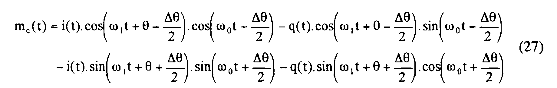


En posant à nouveau ω2 = ω1 + ω0, on retrouve l'expression du signal m(t) formulée dans le cas idéal (équation (4), avec g = 1) avec un gain cos Δ. En considérant cosΔ ≈ 1 - Δ2 / 2 ≈ 1, on simplifie le système de correction sans dégrader la qualité signal puisque ce gain s'applique aux deux voies i(t) et q(t). Si Δ = 5°, l'erreur résultante est d'environ 0,4% sur l'amplitude du signal émis.By setting again ω 2 = ω 1 + ω 0 , we find the expression of the signal m (t) formulated in the ideal case (equation (4), with g = 1) with a gain cos Δ. By considering cosΔ ≈ 1 - Δ 2/2 ≈ 1, the correction system is simplified without degrading the signal quality since this gain applies to the two channels i (t) and q (t). If Δ = 5 °, the resulting error is approximately 0.4% on the amplitude of the transmitted signal.
L'expression simplifiée des deux voies corrigées en gain et en
phase m1c(t) et m2c(t) s'écrit :

En d'autres termes, les moyens 11 d'application d'une correction aux deux signaux m1(t) et m2(t) appliquent :
- sur la première voie : un gain égal à (1 + Δg/2g), ainsi qu'un déphasage égal à (- Δ/2) ;
- sur la seconde voie : un gain égal à (1 - Δg/2g), ainsi qu'un déphasage égal à (+ Δ/2).
- on the first channel: a gain equal to (1 + Δg / 2g), as well as a phase shift equal to (- Δ / 2);
- on the second channel: a gain equal to (1 - Δg / 2g), as well as a phase shift equal to (+ Δ / 2).
De cette manière, on évite toute opération de division pour le calcul du signal corrigé ; dans l'hypothèse où la valeur théorique du gain 'g' est choisie de façon à être un multiple d'une puissance de 2.In this way, any division operation is avoided for the calculation of the corrected signal; assuming that the theoretical gain value 'g' is chosen so as to be a multiple of a power of 2.
Les algorithmes de calcul de Δg et Δ ont été simulés avec succès : l'erreur est compensée après 5 itérations au plus, selon les ordres de grandeur de Δg et Δ (jusqu'à 10 % et 8° respectivement) et avec une erreur allant jusqu'à 12% sur la valeur de g3.The algorithms for calculating Δg and Δ have been successfully simulated: the error is compensated after 5 iterations at most, according to the orders of magnitude of Δg and Δ (up to 10% and 8 ° respectively) and with a error of up to 12% on the value of g 3 .
A travers la description détaillée ci-dessus de deux modes de réalisation particuliers, la nouvelle architecture d'émetteur radiofréquence selon la présente invention a été décrite.Through the detailed description above of two embodiments individuals, the new radiofrequency transmitter architecture according to the The present invention has been described.
On rappelle qu'elle combine les avantages de l'émetteur à conversion directe (pas de fréquence image) sans en avoir les inconvénients (pas de dégradation du signal utile). Grâce au système d'auto-calibrage, les erreurs introduites par la partie analogique sensible aux imperfections sont compensées dans le domaine numérique. Ainsi, le signal résultant qui est émis a des caractéristiques proches du cas idéal.Remember that it combines the advantages of the conversion transmitter direct (no frame rate) without having the disadvantages (no degradation of the useful signal). Thanks to the self-calibration system, errors introduced by the analog part sensitive to imperfections are compensated in the digital domain. Thus, the resulting signal which is emitted has characteristics close to the ideal case.
Les fonctions de traitement du signal sont réalisées dans le domaine
numérique afin d'en exploiter la précision et le fort degré d'intégration sur
silicium. Le convertisseur analogique/numérique (CAN) 14 est par exemple de
type « delta-sigma passe-bande », dont la fréquence de travail est de préférence
identique à celle des deux CNA 51 et 52. Le filtre analogique passe-bas 13 a des
contraintes relâchées : un filtre d'ordre 2 est suffisant dans la plupart des cas. The signal processing functions are performed in the digital domain in order to exploit its precision and the high degree of integration on silicon. The analog / digital converter (ADC) 14 is for example of the “delta-sigma bandpass” type, the working frequency of which is preferably identical to that of the two DACs 5 1 and 5 2 . The analog low-
L'émetteur radiofréquence selon l'invention présente une complexité relativement faible comparée au reste de la chaíne d'émission et possède l'avantage d'être complètement intégrable sur silicium.The radio frequency transmitter according to the invention has a complexity relatively low compared to the rest of the broadcast chain and has the advantage of being completely integrable on silicon.
Claims (13)
Applications Claiming Priority (2)
| Application Number | Priority Date | Filing Date | Title |
|---|---|---|---|
| FR9903768A FR2791506B1 (en) | 1999-03-23 | 1999-03-23 | RADIO FREQUENCY TRANSMITTER WITH HIGH DEGREE OF INTEGRATION AND WITH IMAGE CANCELLATION, POSSIBLY SELF-CALIBRATED |
| FR9903768 | 1999-03-23 |
Publications (2)
| Publication Number | Publication Date |
|---|---|
| EP1039628A1 true EP1039628A1 (en) | 2000-09-27 |
| EP1039628B1 EP1039628B1 (en) | 2005-08-31 |
Family
ID=9543657
Family Applications (1)
| Application Number | Title | Priority Date | Filing Date |
|---|---|---|---|
| EP00460019A Expired - Lifetime EP1039628B1 (en) | 1999-03-23 | 2000-03-02 | Highly integrated radio frequency transmitter with image rejection, optionally auto-calibrated |
Country Status (4)
| Country | Link |
|---|---|
| US (2) | US6668024B1 (en) |
| EP (1) | EP1039628B1 (en) |
| DE (1) | DE60022247T2 (en) |
| FR (1) | FR2791506B1 (en) |
Cited By (6)
| Publication number | Priority date | Publication date | Assignee | Title |
|---|---|---|---|---|
| WO2003005562A2 (en) * | 2001-07-02 | 2003-01-16 | Nokia Corporation | Radio receiver using a feedback loop to compensate i/q amplitude errors, and method |
| WO2003023948A2 (en) * | 2001-09-12 | 2003-03-20 | Infineon Technologies Ag | Transmitter arrangement especially for mobile radio |
| KR100457175B1 (en) * | 2002-12-14 | 2004-11-16 | 한국전자통신연구원 | Quadrature modulation transmitter |
| EP1536554A2 (en) * | 2003-11-28 | 2005-06-01 | Samsung Electronics Co., Ltd. | Digital frequency converter |
| FR2914515A1 (en) * | 2007-04-02 | 2008-10-03 | St Microelectronics Sa | CALIBRATION IN A RADIO FREQUENCY TRANSMIT MODULE |
| CN102460978A (en) * | 2009-06-23 | 2012-05-16 | 诺基亚公司 | Dual channel transmission |
Families Citing this family (5)
| Publication number | Priority date | Publication date | Assignee | Title |
|---|---|---|---|---|
| DE60109645T2 (en) * | 2000-12-18 | 2006-02-09 | Koninklijke Philips Electronics N.V. | GENERATION OF TWO SIGNALS THROUGH 90 DEGREES |
| US7177372B2 (en) * | 2000-12-21 | 2007-02-13 | Jian Gu | Method and apparatus to remove effects of I-Q imbalances of quadrature modulators and demodulators in a multi-carrier system |
| US7647028B2 (en) * | 2005-04-06 | 2010-01-12 | Skyworks Solutions, Inc. | Internal calibration system for a radio frequency (RF) transmitter |
| DE102010027566A1 (en) * | 2010-05-18 | 2011-11-24 | Rohde & Schwarz Gmbh & Co. Kg | Signal generator with digital intermediate frequency and digital fine tuning |
| WO2018024333A1 (en) * | 2016-08-04 | 2018-02-08 | Telefonaktiebolaget Lm Ericsson (Publ) | Method and transmitter for transmit beamforming in a wireless communication system |
Citations (3)
| Publication number | Priority date | Publication date | Assignee | Title |
|---|---|---|---|---|
| US5351016A (en) * | 1993-05-28 | 1994-09-27 | Ericsson Ge Mobile Communications Inc. | Adaptively self-correcting modulation system and method |
| EP0692867A1 (en) * | 1994-07-11 | 1996-01-17 | Nec Corporation | FM modulation circuit and method |
| WO1998011665A1 (en) * | 1996-09-16 | 1998-03-19 | Ericsson Inc. | Method and apparatus for detecting and compensating for undesired phase shift in a radio transceiver |
Family Cites Families (2)
| Publication number | Priority date | Publication date | Assignee | Title |
|---|---|---|---|---|
| WO1995006987A1 (en) * | 1993-09-03 | 1995-03-09 | Ntt Mobile Communications Network Inc. | Code division multiplex transmitter/receiver |
| US6298096B1 (en) * | 1998-11-19 | 2001-10-02 | Titan Corporation | Method and apparatus for determination of predistortion parameters for a quadrature modulator |
-
1999
- 1999-03-23 FR FR9903768A patent/FR2791506B1/en not_active Expired - Fee Related
-
2000
- 2000-03-02 EP EP00460019A patent/EP1039628B1/en not_active Expired - Lifetime
- 2000-03-02 DE DE60022247T patent/DE60022247T2/en not_active Expired - Lifetime
- 2000-03-06 US US09/518,944 patent/US6668024B1/en not_active Ceased
-
2005
- 2005-12-23 US US11/318,388 patent/USRE42043E1/en not_active Expired - Fee Related
Patent Citations (3)
| Publication number | Priority date | Publication date | Assignee | Title |
|---|---|---|---|---|
| US5351016A (en) * | 1993-05-28 | 1994-09-27 | Ericsson Ge Mobile Communications Inc. | Adaptively self-correcting modulation system and method |
| EP0692867A1 (en) * | 1994-07-11 | 1996-01-17 | Nec Corporation | FM modulation circuit and method |
| WO1998011665A1 (en) * | 1996-09-16 | 1998-03-19 | Ericsson Inc. | Method and apparatus for detecting and compensating for undesired phase shift in a radio transceiver |
Cited By (13)
| Publication number | Priority date | Publication date | Assignee | Title |
|---|---|---|---|---|
| WO2003005562A2 (en) * | 2001-07-02 | 2003-01-16 | Nokia Corporation | Radio receiver using a feedback loop to compensate i/q amplitude errors, and method |
| WO2003005562A3 (en) * | 2001-07-02 | 2004-06-10 | Nokia Corp | Radio receiver using a feedback loop to compensate i/q amplitude errors, and method |
| WO2003023948A2 (en) * | 2001-09-12 | 2003-03-20 | Infineon Technologies Ag | Transmitter arrangement especially for mobile radio |
| WO2003023948A3 (en) * | 2001-09-12 | 2003-09-18 | Infineon Technologies Ag | Transmitter arrangement especially for mobile radio |
| US7409008B2 (en) | 2001-09-12 | 2008-08-05 | Infineon Technologies Ag | Transmitting arrangement for mobile radio |
| KR100457175B1 (en) * | 2002-12-14 | 2004-11-16 | 한국전자통신연구원 | Quadrature modulation transmitter |
| EP1536554A3 (en) * | 2003-11-28 | 2005-07-13 | Samsung Electronics Co., Ltd. | Digital frequency converter |
| EP1536554A2 (en) * | 2003-11-28 | 2005-06-01 | Samsung Electronics Co., Ltd. | Digital frequency converter |
| CN100448163C (en) * | 2003-11-28 | 2008-12-31 | 三星电子株式会社 | Digital frequency converter |
| US7515647B2 (en) | 2003-11-28 | 2009-04-07 | Samsung Electronics Co., Ltd | Digital frequency converter |
| FR2914515A1 (en) * | 2007-04-02 | 2008-10-03 | St Microelectronics Sa | CALIBRATION IN A RADIO FREQUENCY TRANSMIT MODULE |
| US8238469B2 (en) | 2007-04-02 | 2012-08-07 | St-Ericsson Sa | Calibration in a radio frequency transmission module |
| CN102460978A (en) * | 2009-06-23 | 2012-05-16 | 诺基亚公司 | Dual channel transmission |
Also Published As
| Publication number | Publication date |
|---|---|
| US6668024B1 (en) | 2003-12-23 |
| FR2791506A1 (en) | 2000-09-29 |
| DE60022247T2 (en) | 2006-07-20 |
| DE60022247D1 (en) | 2005-10-06 |
| EP1039628B1 (en) | 2005-08-31 |
| FR2791506B1 (en) | 2001-06-22 |
| USRE42043E1 (en) | 2011-01-18 |
Similar Documents
| Publication | Publication Date | Title |
|---|---|---|
| EP0624959B1 (en) | FM receiver with an oversampling circuit | |
| EP0941588B1 (en) | Method and device for mixed analog and digital broadcast of a radio programme broadcast by the same transmitter | |
| EP1331729A1 (en) | A predistortion compensated linear amplifier | |
| EP0616434A1 (en) | Digital superheterodyne receiver and method for baseband filtering | |
| FR3046709B1 (en) | RF RECEIVER WITH FREQUENCY TRACKING | |
| EP1835630A1 (en) | Method for minimising leakage signals in full-duplex systems and a corresponding device | |
| EP1259077A1 (en) | Electronic component for decoding of a radio transmission channel carrying digitally coded information, especially for digital satellite broadcast | |
| EP1039628B1 (en) | Highly integrated radio frequency transmitter with image rejection, optionally auto-calibrated | |
| EP1269707B1 (en) | Device for producing a phase and amplitude modulated radio frequency signal | |
| EP1306978B1 (en) | Direct conversion receiver for a communication system using a non-constant envelope modulation | |
| FR2767429A1 (en) | DEVICE FOR MATCHING DELAYS IN A POWER AMPLIFIER | |
| WO2007101885A1 (en) | Device for receiving and/or transmitting radio frequency signals with noise reduction | |
| FR2728416A1 (en) | PROCESS FOR BALANCING THE CHANNELS OF A "LINC" TYPE AMPLIFIER | |
| EP0150880B1 (en) | Demodulator using phase-locked loop | |
| CA2201387A1 (en) | Heavy-duty phase estimator and recuperator for digital signals affected by phase jitter | |
| FR2798790A1 (en) | FREQUENCY SYNTHESIS DEVICE | |
| FR2781948A1 (en) | Quasi-direct conversion radio receiver architecture for use in mobile telephone, heterodyning RF input to low IF before digitizing | |
| EP1417750B1 (en) | Mixer circuit with image frequency rejection which is intended, in particular, for an rf receiver with zero or low intermediate frequency | |
| EP0169093A1 (en) | Receiver for time division multiplexed television transmission comprising a frequency demodulator | |
| EP2514099B1 (en) | Device and method for receiving rf signals based on heterodyne architecture using complex if sub-sampling | |
| WO2016124835A1 (en) | Method and system for suppressing a parasite signal received by a satellite payload | |
| EP1465429B1 (en) | Electronic component for decoding digital satellite television signals | |
| FR2755808A1 (en) | ESTIMATOR OF A FAULT IN OPERATION OF A MODULATOR IN QUADRATURE AND MODULATION STAGE USING IT | |
| FR2794311A1 (en) | CARRIER FREQUENCY REDUCING PASSET FILTER | |
| EP1089427A1 (en) | Method for the comparison of the amplitudes of two electrical signals |
Legal Events
| Date | Code | Title | Description |
|---|---|---|---|
| PUAI | Public reference made under article 153(3) epc to a published international application that has entered the european phase |
Free format text: ORIGINAL CODE: 0009012 |
|
| AK | Designated contracting states |
Kind code of ref document: A1 Designated state(s): DE FI GB IT NL SE |
|
| AX | Request for extension of the european patent |
Free format text: AL;LT;LV;MK;RO;SI |
|
| 17P | Request for examination filed |
Effective date: 20010119 |
|
| AKX | Designation fees paid |
Free format text: DE FI GB IT NL SE |
|
| GRAP | Despatch of communication of intention to grant a patent |
Free format text: ORIGINAL CODE: EPIDOSNIGR1 |
|
| GRAS | Grant fee paid |
Free format text: ORIGINAL CODE: EPIDOSNIGR3 |
|
| GRAA | (expected) grant |
Free format text: ORIGINAL CODE: 0009210 |
|
| AK | Designated contracting states |
Kind code of ref document: B1 Designated state(s): DE FI GB IT NL SE |
|
| PG25 | Lapsed in a contracting state [announced via postgrant information from national office to epo] |
Ref country code: NL Free format text: LAPSE BECAUSE OF FAILURE TO SUBMIT A TRANSLATION OF THE DESCRIPTION OR TO PAY THE FEE WITHIN THE PRESCRIBED TIME-LIMIT Effective date: 20050831 Ref country code: FI Free format text: LAPSE BECAUSE OF FAILURE TO SUBMIT A TRANSLATION OF THE DESCRIPTION OR TO PAY THE FEE WITHIN THE PRESCRIBED TIME-LIMIT Effective date: 20050831 Ref country code: IT Free format text: LAPSE BECAUSE OF FAILURE TO SUBMIT A TRANSLATION OF THE DESCRIPTION OR TO PAY THE FEE WITHIN THE PRESCRIBED TIME-LIMIT;WARNING: LAPSES OF ITALIAN PATENTS WITH EFFECTIVE DATE BEFORE 2007 MAY HAVE OCCURRED AT ANY TIME BEFORE 2007. THE CORRECT EFFECTIVE DATE MAY BE DIFFERENT FROM THE ONE RECORDED. Effective date: 20050831 |
|
| REG | Reference to a national code |
Ref country code: GB Ref legal event code: FG4D Free format text: NOT ENGLISH |
|
| REF | Corresponds to: |
Ref document number: 60022247 Country of ref document: DE Date of ref document: 20051006 Kind code of ref document: P |
|
| PG25 | Lapsed in a contracting state [announced via postgrant information from national office to epo] |
Ref country code: SE Free format text: LAPSE BECAUSE OF FAILURE TO SUBMIT A TRANSLATION OF THE DESCRIPTION OR TO PAY THE FEE WITHIN THE PRESCRIBED TIME-LIMIT Effective date: 20051130 |
|
| GBT | Gb: translation of ep patent filed (gb section 77(6)(a)/1977) |
Effective date: 20051214 |
|
| NLV1 | Nl: lapsed or annulled due to failure to fulfill the requirements of art. 29p and 29m of the patents act | ||
| PLBE | No opposition filed within time limit |
Free format text: ORIGINAL CODE: 0009261 |
|
| STAA | Information on the status of an ep patent application or granted ep patent |
Free format text: STATUS: NO OPPOSITION FILED WITHIN TIME LIMIT |
|
| 26N | No opposition filed |
Effective date: 20060601 |
|
| REG | Reference to a national code |
Ref country code: GB Ref legal event code: 732E |
|
| PGFP | Annual fee paid to national office [announced via postgrant information from national office to epo] |
Ref country code: GB Payment date: 20120227 Year of fee payment: 13 |
|
| PGFP | Annual fee paid to national office [announced via postgrant information from national office to epo] |
Ref country code: DE Payment date: 20120330 Year of fee payment: 13 |
|
| GBPC | Gb: european patent ceased through non-payment of renewal fee |
Effective date: 20130302 |
|
| REG | Reference to a national code |
Ref country code: DE Ref legal event code: R119 Ref document number: 60022247 Country of ref document: DE Effective date: 20131001 |
|
| PG25 | Lapsed in a contracting state [announced via postgrant information from national office to epo] |
Ref country code: GB Free format text: LAPSE BECAUSE OF NON-PAYMENT OF DUE FEES Effective date: 20130302 Ref country code: DE Free format text: LAPSE BECAUSE OF NON-PAYMENT OF DUE FEES Effective date: 20131001 |