EP1040589B1 - Distributed radio telephone for use in a vehicle - Google Patents
Distributed radio telephone for use in a vehicle Download PDFInfo
- Publication number
- EP1040589B1 EP1040589B1 EP98958005A EP98958005A EP1040589B1 EP 1040589 B1 EP1040589 B1 EP 1040589B1 EP 98958005 A EP98958005 A EP 98958005A EP 98958005 A EP98958005 A EP 98958005A EP 1040589 B1 EP1040589 B1 EP 1040589B1
- Authority
- EP
- European Patent Office
- Prior art keywords
- vehicle
- communication system
- unit
- control unit
- base unit
- Prior art date
- Legal status (The legal status is an assumption and is not a legal conclusion. Google has not performed a legal analysis and makes no representation as to the accuracy of the status listed.)
- Expired - Lifetime
Links
Images


Classifications
-
- H—ELECTRICITY
- H04—ELECTRIC COMMUNICATION TECHNIQUE
- H04B—TRANSMISSION
- H04B1/00—Details of transmission systems, not covered by a single one of groups H04B3/00 - H04B13/00; Details of transmission systems not characterised by the medium used for transmission
- H04B1/38—Transceivers, i.e. devices in which transmitter and receiver form a structural unit and in which at least one part is used for functions of transmitting and receiving
- H04B1/3822—Transceivers, i.e. devices in which transmitter and receiver form a structural unit and in which at least one part is used for functions of transmitting and receiving specially adapted for use in vehicles
-
- B—PERFORMING OPERATIONS; TRANSPORTING
- B60—VEHICLES IN GENERAL
- B60R—VEHICLES, VEHICLE FITTINGS, OR VEHICLE PARTS, NOT OTHERWISE PROVIDED FOR
- B60R11/00—Arrangements for holding or mounting articles, not otherwise provided for
- B60R11/02—Arrangements for holding or mounting articles, not otherwise provided for for radio sets, television sets, telephones, or the like; Arrangement of controls thereof
- B60R11/0241—Arrangements for holding or mounting articles, not otherwise provided for for radio sets, television sets, telephones, or the like; Arrangement of controls thereof for telephones
-
- H—ELECTRICITY
- H04—ELECTRIC COMMUNICATION TECHNIQUE
- H04M—TELEPHONIC COMMUNICATION
- H04M1/00—Substation equipment, e.g. for use by subscribers
- H04M1/60—Substation equipment, e.g. for use by subscribers including speech amplifiers
- H04M1/6033—Substation equipment, e.g. for use by subscribers including speech amplifiers for providing handsfree use or a loudspeaker mode in telephone sets
- H04M1/6041—Portable telephones adapted for handsfree use
- H04M1/6075—Portable telephones adapted for handsfree use adapted for handsfree use in a vehicle
- H04M1/6083—Portable telephones adapted for handsfree use adapted for handsfree use in a vehicle by interfacing with the vehicle audio system
- H04M1/6091—Portable telephones adapted for handsfree use adapted for handsfree use in a vehicle by interfacing with the vehicle audio system including a wireless interface
-
- H—ELECTRICITY
- H04—ELECTRIC COMMUNICATION TECHNIQUE
- H04M—TELEPHONIC COMMUNICATION
- H04M2250/00—Details of telephonic subscriber devices
- H04M2250/02—Details of telephonic subscriber devices including a Bluetooth interface
Definitions
- the present invention relates generally to mobile radio telephones and, more particularly, to a distributed mobile radio telephone for use in a vehicle.
- a standard, handheld cellular telephone may be used by the driver.
- the power for the handheld cellular telephone can be provided by the handheld unit's own battery pack or by an adapter which plugs into the vehicle's cigarette lighter.
- a standard handheld cellular telephone can be held by a cradle mounted within the interior of the vehicle.
- the cradle may include an external speaker and microphone to permit hands-free operation once a call is established.
- the vehicle may be provided with a built-in cellular telephone which is permanently fixed to the vehicle.
- the first solution using a standard handheld terminal -- provides versatility and ease of Installation and maintenance at the expense of ergonomics, aesthetics, and phone performance.
- using a handheld cellular telephone requires awkward exertion on the part of the driver to position the phone next to a window. Even if the phone can be positioned near a window, the vehicle's body often obscures the RF path between the phone's antenna and the cellular base station thereby limiting the phone's performance. Also, the only functions available to the driver are those provided by the handheld phone.
- the second solution mounting a handheld cellular telephone in a cradle is an improvement over the first solution. Nevertheless, this solution also has drawbacks, primarily concerning ergonomics, aesthetics, and phone performance. Since the cradle is normally mounted outside the driver's normal line of sight, the driver must shift his or her field of vision in order to use the cellular telephone. Further, cradles are normally sold as after-market devices whose appearance is not necessarily harmonious with the vehicle's interior decoration. Cradles often suffer from dangling power cables, microphones, and control buttons. As the first solution, the driver is limited to the functions provided by the handheld phone. Also, unless an external booster is used -- which brings its own problems regarding expense, installation, and aesthetics -- the phone's performance is limited by its power amplifier, which is designed to meet the battery constraints of a handheld terminal.
- the trade off is in ergonomics, versatility, ease of maintenance, and ease of modification.
- the phone's controls are normally placed outside the driver's field of vision.
- the driver is required to shift his or her field of vision in order to operate the phone.
- the freedom of having a detachable handheld telephone is lost.
- the phone cannot be removed from the vehicle when the driver departs from the vehicle.
- new features and functions cannot be readily added to a built in phone, nor can a built in phone be readily returned to its manufacturer for maintenance or upgrade.
- US-A-4 629 828 describes a signal transmission apparatus for a steering operation board adapted to transmit signals between a control unit on the vehicle body and the steering operation board in the vicinity of steering wheels wherein the steering Operation board includes an acoustic-electric converter such as a microphone.
- the signal transmission apparatus comprises a steering operation board being equipped on the steering wheel and including the microphone. It further comprises a control unit being equipped at a fixed position on the vehicle body mechanically separated from the steering operation board.
- the steering operation board contains a light signal transmission means composed of a light emitting means adapted to convert an electric signal from the steering operation board to a light beam which is sent to a light receiving means contained in the control unit.
- the light receiving means reconverts the received light beam into an electric signal in accordance with the intensity of the light beam.
- GB-A-2 237 954 relates to a vehicle telephone apparatus for use with a cellular telephone.
- the apparatus comprises a keypad located on the steering wheel of the vehicle, an electromagnetic signal transmitter connectable to the keypad, an electromagnetic signal receiver to be mounted on a fixed part of the vehicle spaced apart from the transmitter and a programmable computer means operative to process the signal from the signal receiver into a suitable serial code for supply to the telephone transceiver, whereby the telephone may be operated from the keypad on the steering wheel without removing the driver's hand from the steering wheel.
- US-A-4 455 454 describes a telephone transmission system on a road-vehicle for telephone transmission between a branch telephone device equipped on a steering wheel and a mobile telephone station on a road-vehicle.
- the system comprises a dialling control board supporting mechanism mounted on the steering wheel adapted to support a dialling control board in stationary state relative to the road-vehicle irrespective of a rotation of the steering wheel. Dialling information input by the driver using key switches on the dialling control board is transmitted between the dialling control board on the steering wheel and the fixed electric controller through a combination of slip rings and brushes or a pair of electric coils.
- the mobile telephony device and the branch connection device are connected to the fixed electric controller in order to provide a hands free telephone transmission system on a road-vehicle.
- the radiotelephone for use in a vehicle.
- the radiotelephone includes a base unit mounted within the vehicle having a wide area transceiver for communicating with a station outside the vehicle, a control unit disposed in the vehicle remotely from the base unit, and a local area network for establishing a communication link between the base unit and the control unit.
- the local area network is adapted to transmit control and data signals between the base unit and the control unit.
- the control unit includes a keypad for entering commands and data which are transmitted to the base unit via the local area network, and a display for displaying information to the user.
- the control unit may also include a speaker and a microphone. Alternatively, the speaker and microphone may be contained in a remote audio unit which is linked to the base unit via the local area network.
- a first local area transceiver is located with the control unit, and a second local area transceiver is located with the base unit to provide wireless communication between the base unit and the control unit. 1f a remote audio unit is used, a third local area transceiver would be located in the remote audio unit.
- the control unit is typically mounted on the steering wheel of the vehicle.
- the control unit may be fully integrated into the steering column of the vehicle or, alternatively, may be a self-contained unit which attaches to the steering wheel of the vehicle.
- Power for the control unit may be provided by the vehicle's battery, by a solar panel disposed within the vehicle, or by its own batteries.
- the base unit is a closed box which is concealed within the vehicle.
- the base unit may be mounted in a console or in a trunk of the vehicle. User interaction with the base unit is strictly through the control unit.
- certain components of the base unit such as the wide area transceiver, may be embodied in cards which plug into the base unit. This allows for easy upgrading and repair of the base unit.
- the base unit could comprise a standard hand-held radiotelephone.
- the local area transceiver could be incorporated into the radiotelephone, or may reside in removable battery pack which attaches to the radiotelephone.
- a third option is to place the transceiver in a separate adapter which connects to the radiotelephone.
- the adapter may consist of a cradle for receiving and holding the hand-held radiotelephone.
- the distributed components of the radiotelephone may communicate over a LAN which is inherent to the vehicle.
- the vehicle's manufacturer will include a local area network in a vehicle which ties together various systems of the vehicle.
- the control unit, base unit, and audio units may use the excess capacity of the vehicle's own LAN to communicate with one another.
- the radiotelephone may be used to augment or work with the inherent systems on the vehicle.
- the vehicle's security system could be programmed to place a telephone call notifying local law enforcement authorities if the vehicle is stolen. This notification may include the position of the vehicle if the vehicle also has an on-board GPS receiver.
- the mobile phone system 10 is particularly adapted for use in a vehicle.
- the mobile phone system 10 is distributed over a number of separate and distinct physical units which are positioned at different locations within the vehicle.
- the separate physical units communicate with one another through a local wireless communications link.
- the mobile phone system preferably includes two physical units: a base unit 20 and a control unit 40.
- the base unit 20 includes a fully functional transceiver capable of sending and receiving radio signals to and from a station located outside of the vehicle.
- the control unit 40 includes the Interface elements needed by the user to control the transceiver.
- the base unit 20 is located in the trunk or console of the vehicle, or under the seat of a vehicle.
- the control unit 40 is preferably integrated into the vehicle's steering wheel or, alternatively, may be attached to the steering wheel.
- the base unit 20 includes an RF transceiver 24, control logic 26, volatile memory (RAM) 28, non-volatile memory (ROM) 30, and a modem 32.
- the RF transceiver 24 may be, for example, a class 1 mobile phone transceiver capable of transmitting and receiving radio signals to and from stations outside of the vehicle.
- the control logic 26 controls the operation of the transceiver 24 and modem 32 according to instructions stored in the non-volatile memory 30.
- the volatile memory 28 provides memory for temporarily storing data which is needed by the control logic 26 during operation of the mobile phone system 10.
- the modem 32 provides a communications link between the base unit 20 and the control unit 40.
- the base unit 20 includes a housing 22 which contains the electronic components of the base unit 20.
- the control logic 26 is contained in a main circuit board.
- the RF transceiver 24 and non-volatile memory 30 are contained in separate cards which plug into sockets on the main circuit board.
- the RF transceiver 24 and non-volatile memory 30 may be contained in a single card or may be on separate cards. By placing the RF transceiver 24 and non-volatile memory 30 on removable cards, these components may be readily replaced or upgraded. For example, a transceiver 24 that operates according to one cellular standard may be replaced by a transceiver 24 operating according to a different cellular standard. Similarly, upgrades or enhancements to the functionality of the phone system 10 can be made by replacing a memory card.
- FIG. 3 is a block diagram of the control unit 40.
- the control unit 40 is preferably integrated into the vehicle's steering wheel.
- the control unit 40 includes a keypad 44, display 46, microphone 48, and speaker 50 which serves as the interface elements between the user and the base unit 20.
- the keypad 44 is used to enter data and commands by the user. For example, a common use for the keypad 44 would be to enter a telephone number and "send" command to establish an outgoing call.
- the display 46 is used to display information, such as the number dialed and call status information, to the user.
- Microphone 48 converts the user's voice into audio signals which are to be transmitted by the base unit 20 to a remote station located outside the vehicle.
- the speaker 50 converts audio signals received by the base unit 20 into audible sounds which can be heard by the user.
- Control logic 52 controls the operation of the control unit 40 according to instructions stored in its internal memory.
- a modem 54 contained within the control unit 40 provides a communications link between the control unit 40 and the base unit 20.
- the modems 32 and 54 that provide the communications link between the base unit 20 and control unit 40 are short range RF transceivers which transmit and receive signals over a limited distance.
- the modems 32 and 54 preferably operate in the license free RF band authorized internationally at 2.4 GHz. Slow frequency hopping is used to combat interference and fading. A binary, frequency modulation scheme is used for transmissions.
- the physical layer of the link provides a gross data rate of 1 mbs with a frame period of 1.25 ms.
- a packet switching, link control protocol is used wherein each packet is transmitted in a different frequency hop.
- Two full duplex logical channels are derived from the flow of packets -- a synchronous voice channel that is used to carry 64 kbs sampled audio signals with robust source and channel encoding, and an asynchronous data channel with ARQ error recovery and a capacity of 170 to 200 kbs.
- the remote audio unit 60 is an accessory whose primary purpose is to enhance audio performance by providing multiple microphones for noise cancellation and external speakers for superior voice output fidelity.
- the remote audio unit 60 includes a pair of speakers 62, each with its own power amplifier, and a microphone 64. Alternatively, the speakers 62 and microphone 64 may be placed in separate audio units 60 so that they may be positioned within the vehicle independently of one another.
- the remote audio unit 60 includes a modem 68 for communicating with the base unit 20. Control logic 66 controls the operation of the remote audio unit 60.
- the driver of a vehicle may initiate a telephone call by entering a telephone number using the keypad 44 and pressing a "send" key.
- the "send" instruction is transmitted via modems 32 and 54 from the control unit 40 to the base unit 20 along with the number to be dialed.
- the base unit 20 then initiates the call according to normal cellular telephony practices.
- audio signals received by the base unit 20 are transmitted to either the control unit 40 or to a remote audio unit 60 and are converted to audible sounds by the speaker 50 or 64.
- the microphone 48 in the control unit 40 converts the driver's voice into audio signals which are transmitted to the base unit 20 for further transmission to a remote station outside of the vehicle.
- the present invention overcomes the limitations of the prior art by eliminating the need to pass either RF signals or wires through the clock springs in the steering wheel. Instead, control information and audio signals are transmitted from the control unit 40 in the steering wheel to the base unit 20 by RF without passing through the clock springs of the steering wheel.
- the clock spring is used only to provide operating power to the control unit 40 in the steering wheel.
- the radiotelephone 100 includes a main housing 102 and a removable battery pack 130.
- the main housing 102 contains an RF transceiver 103, memory 104, control logic 106, keypad 108, display 110, audio processing circuits 112, microphone 114 and speaker 116.
- the main housing 102 may also include a GPS receiver 120 for receiving position data from satellites.
- the battery pack 130 includes a power source 132 which may comprise either rechargeable batteries or an adapter which plugs into a power source.
- the hand-held telephone 100 is no different than a conventional hand-held radiotelephone.
- the hand-held telephone 100 of the present invention includes a built-in modem 118 for communicating with a built-in control unit 40 in a vehicle.
- the modem 118 is shown in the main housing 102 of the hand-held telephone 100.
- the modem 118 could also be contained in the removable battery pack 130 as shown in dotted lines in Figure 6.
- One advantage to the latter approach is that the modem 118 is detachable and therefore may be offered as an optional accessory to the hand-held phone 100 rather than as an integral part of the phone 100.
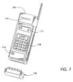
- Figures 7-9 illustrate a hand-held radiotelephone for a distributed phone system that uses a modem adapter 150.
- the modem adapter 150 is in the form of a detachable module that plugs into a system interface on the hand-held telephone 100.
- the modem adapter 150 includes a modem 152 to allow communication with a control unit 40 and a power adapter 154 to provide power to the hand-held telephone 100.
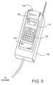
- the modem adapter 150 may also be in the form of a cradle that mounts in a vehicle as shown in Figure 9.
- the hand-held radiotelephone 100 of the present invention may be operated in a conventional manner. That is, the hand-held telephone's own keypad 108, display 110, microphone 114 and speaker 116 operate in a conventional manner to provide a user interface. When placed in a vehicle mode, the hand-held radiotelephone's interface elements may be at least partially disabled, and control passes instead to the control unit 40 which is integrated into the vehicle's steering wheel. The hand-held radiotelephone 100 communicates with the control unit 40 via modem 118.
- the embodiments of the distributed radiotelephone system 10 of the present invention described above rely on a low power, limited distance RF link to provide communication between a base unit 10, control unit 40, and audio unit 60.
- Those skilled in the art will recognize, however, that other types of communication links may also be used in connection with the present invention.
- one alternative would be to use a fiber optic network to link the distinct physical units of the distributed radiotelephone system 10.
- a fiber optic network is installed in the vehicle at the time of its manufacture to link the vehicle's ignition, charging, securing, and accessory systems.
- the physical units of the distributed radiotelephone 10 of the present invention may communicate with one another using such an inherent vehicle network.
- the physical units of the distributed phone system 10 thus become attachments to the vehicle's inherent network.
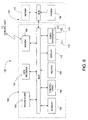
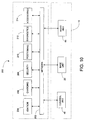
- FIG 10 is a block diagram of a distributed radiotelephone system 10 which uses an inherent vehicle network 200 to communicate among the various physical units.
- the radiotelephone system includes a base unit 20, control unit 40, and optionally, an audio unit 60 which connect via modem to an inherent vehicle network indicated generally at 200.
- the vehicle network 200 includes a communications network 202 such as a fiber optic network. Attached to the communications network 202 are the vehicle's ignition system 204, charging system 206, security system 208, positioning system 210, diagnostic system 212, and various accessories 214. Since these inherent vehicle systems attach to the same network 202 as the distributed radiotelephone 10 of the present invention, the radiotelephone 10 of the present invention may operate in conjunction with the vehicle systems to augment such systems.
- the vehicle security system 208 could be programmed to place a telephone call notifying local law enforcement authorities if the vehicle is stolen. This notification may include the position of the vehicle if either the vehicle or radiotelephone 10 has a GPS receiver.
- the radiotelephone 10 may be used to provide telemetry that carries diagnostic information concerning the vehicle itself, or software upgrades to various microprocessor functions for various vehicle systems.
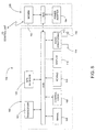
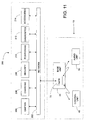
- FIG 11 shows an alternate method for connecting the radiotelephone 10 of the present invention to a vehicle network 200.
- the base unit 20 is connected to the on-board communications network 202 in the vehicle by means of a bridge, gateway, router, packet switch, or similar device.
- the base unit 20 then communicates with the control unit 40 and audio unit 60 via wireless link as previously described.
- the bridge, gateway, or router resides in the base unit 20. but can also be a separate unit.
- the problem associated with connecting to a steering wheel hub are solved by sending control information in baseband digital form over one strand of a multi-strand clock-spring path, or by modulating control information onto a clock-spring path that it used as well for another purpose, such as the clock-spring that powers other electronic devices that are integrated with the steering wheel hub.
- the path so derived is then interconnected to the communications network 202 by a standard modem.
- control unit 40 is replaced by a remote dialing unit 80 having a housing 82 which attaches to the steering wheel of a vehicle by straps, clips, or other suitable fastening means 84.
- the remote data unit 80 is preferably located at the front of the steering wheel. Thus, the user can keep both hands on the steering wheel (at the 10 o'clock and 2 o'clock positions) while driving.
- FIG 13 is a functional diagram of the remote dialing unit 80.
- the remote dialing unit 80 includes a keypad 86 for entering dialing instructions, an encoder 88 for encoding data entered by the user, and a local area transmitter 90 for transmitting dialing instruction to the base unit 20.
- the base unit 20 preferably comprises a radiotelephone 100 as shown in Figures 5 and 6 with the local area transceiver 118 being replaced by a local area receiver capable of receiving transmitted data from the remote data unit 80.
- the RF link is a simple ASK (on/off operation).
- the remote data unit 80 could communicate with a cradle designed to hold the telephone 100.
- the local area receiver would be contained in the cradle and the cradle would send commands to the radiotelephone 100 over the system bus.
Description
- The present invention relates generally to mobile radio telephones and, more particularly, to a distributed mobile radio telephone for use in a vehicle.
- At present, there are three generally accepted ways to provide cellular telephone service to the driver of a vehicle. First, a standard, handheld cellular telephone may be used by the driver. The power for the handheld cellular telephone can be provided by the handheld unit's own battery pack or by an adapter which plugs into the vehicle's cigarette lighter. Second, a standard handheld cellular telephone can be held by a cradle mounted within the interior of the vehicle. The cradle may include an external speaker and microphone to permit hands-free operation once a call is established. Third, the vehicle may be provided with a built-in cellular telephone which is permanently fixed to the vehicle.
- Each of the aforementioned solutions makes undesired tradeoffs among various design goals that include ergonomics, aesthetics, functional versatility, phone performance, expandability, and ease of installation and maintenance. For example, the first solution -- using a standard handheld terminal -- provides versatility and ease of Installation and maintenance at the expense of ergonomics, aesthetics, and phone performance. In brief, using a handheld cellular telephone requires awkward exertion on the part of the driver to position the phone next to a window. Even if the phone can be positioned near a window, the vehicle's body often obscures the RF path between the phone's antenna and the cellular base station thereby limiting the phone's performance. Also, the only functions available to the driver are those provided by the handheld phone.
- The second solution mounting a handheld cellular telephone in a cradle is an improvement over the first solution. Nevertheless, this solution also has drawbacks, primarily concerning ergonomics, aesthetics, and phone performance. Since the cradle is normally mounted outside the driver's normal line of sight, the driver must shift his or her field of vision in order to use the cellular telephone. Further, cradles are normally sold as after-market devices whose appearance is not necessarily harmonious with the vehicle's interior decoration. Cradles often suffer from dangling power cables, microphones, and control buttons. As the first solution, the driver is limited to the functions provided by the handheld phone. Also, unless an external booster is used -- which brings its own problems regarding expense, installation, and aesthetics -- the phone's performance is limited by its power amplifier, which is designed to meet the battery constraints of a handheld terminal.
- The third solution -- a built in cellular phone -- provides improved aesthetics since it is normally designed to be harmonious with the vehicle's interior. The trade off is in ergonomics, versatility, ease of maintenance, and ease of modification. Even in built in phones, the phone's controls are normally placed outside the driver's field of vision. Thus, the driver is required to shift his or her field of vision in order to operate the phone. Moreover, the freedom of having a detachable handheld telephone is lost. The phone cannot be removed from the vehicle when the driver departs from the vehicle. Furthermore, new features and functions cannot be readily added to a built in phone, nor can a built in phone be readily returned to its manufacturer for maintenance or upgrade.
- US-A-4 629 828 describes a signal transmission apparatus for a steering operation board adapted to transmit signals between a control unit on the vehicle body and the steering operation board in the vicinity of steering wheels wherein the steering Operation board includes an acoustic-electric converter such as a microphone. The signal transmission apparatus comprises a steering operation board being equipped on the steering wheel and including the microphone. It further comprises a control unit being equipped at a fixed position on the vehicle body mechanically separated from the steering operation board. The steering operation board contains a light signal transmission means composed of a light emitting means adapted to convert an electric signal from the steering operation board to a light beam which is sent to a light receiving means contained in the control unit. The light receiving means reconverts the received light beam into an electric signal in accordance with the intensity of the light beam. Thus, a wireless transmission of signals is ensured from the steering operation board to the control unit while providing a microphone with relatively high directivity in its sensitivity which is positioned near the driver in the center of the steering wheel.
- GB-A-2 237 954 relates to a vehicle telephone apparatus for use with a cellular telephone. The apparatus comprises a keypad located on the steering wheel of the vehicle, an electromagnetic signal transmitter connectable to the keypad, an electromagnetic signal receiver to be mounted on a fixed part of the vehicle spaced apart from the transmitter and a programmable computer means operative to process the signal from the signal receiver into a suitable serial code for supply to the telephone transceiver, whereby the telephone may be operated from the keypad on the steering wheel without removing the driver's hand from the steering wheel.
- US-A-4 455 454 describes a telephone transmission system on a road-vehicle for telephone transmission between a branch telephone device equipped on a steering wheel and a mobile telephone station on a road-vehicle. The system comprises a dialling control board supporting mechanism mounted on the steering wheel adapted to support a dialling control board in stationary state relative to the road-vehicle irrespective of a rotation of the steering wheel. Dialling information input by the driver using key switches on the dialling control board is transmitted between the dialling control board on the steering wheel and the fixed electric controller through a combination of slip rings and brushes or a pair of electric coils. The mobile telephony device and the branch connection device are connected to the fixed electric controller in order to provide a hands free telephone transmission system on a road-vehicle.
- According to the present invention, there is provided a communication system for a vehicle having a steering wheel according to appended independent Claim 1. Preferred embodiments are defined in the appended dependent claims.
- For a better understanding of the present invention, and to show how the same may be carried into effect, reference will now be made, by way of example, to the accompanying drawings, in which:
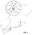
- Figure 1 is a schematic drawing showing the distributed radiotelephone of the present Invention;
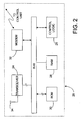
- Figure 2 is a block diagram illustrating the control unit of the radiotelephone;
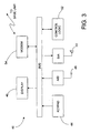
- Figure 3 is a block diagram illustrating the base unit of the radiotelephone;
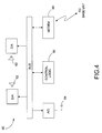
- Figure 4 is a block diagram illustrating an optional audio unit for the radiotelephone;
- Figure 5 is a perspective view of a hand-held radiotelephone for use in the distributed radiotelephone system of the present invention;
- Figure 6 is a block diagram of the hand-held radiotelephone wherein the modern is contained in the radiotelephone housing;
- Figure 7 is a perspective view of the hand-held radiotelephone with a modern adapter in the form of a detachable module;
- Figure 8 is a block diagram of the hand-held radiotelephone with modern adapter;
- Figure 9 is a perspective view of the hand-held radiotelephone with a modern adapter in the form of a cradle;
- Figure 10 is a block diagram of a distributed radiotelephone using an inherent vehicle-based network for communication between separate physical units;
- Figure 11 is a block diagram of a distributed radiotelephone having a base unit connected to a vehicle-based network, and a control unit which communicates with the base unit by wireless link;
- Figure 12 is a schematic diagram of a remote dialing unit for a distributed radiotelephone; and
- Figure 13 is a block diagram of the remote dialing unit.
- The following describes a radiotelephone for use in a vehicle. The radiotelephone includes a base unit mounted within the vehicle having a wide area transceiver for communicating with a station outside the vehicle, a control unit disposed in the vehicle remotely from the base unit, and a local area network for establishing a communication link between the base unit and the control unit. The local area network is adapted to transmit control and data signals between the base unit and the control unit. The control unit includes a keypad for entering commands and data which are transmitted to the base unit via the local area network, and a display for displaying information to the user. The control unit may also include a speaker and a microphone. Alternatively, the speaker and microphone may be contained in a remote audio unit which is linked to the base unit via the local area network. In the radiotelephone, preferably, a first local area transceiver is located with the control unit, and a second local area transceiver is located with the base unit to provide wireless communication between the base unit and the control unit. 1f a remote audio unit is used, a third local area transceiver would be located in the remote audio unit.
- The control unit is typically mounted on the steering wheel of the vehicle. The control unit may be fully integrated into the steering column of the vehicle or, alternatively, may be a self-contained unit which attaches to the steering wheel of the vehicle. Power for the control unit may be provided by the vehicle's battery, by a solar panel disposed within the vehicle, or by its own batteries.
- In one arrangement, the base unit is a closed box which is concealed within the vehicle. For example, the base unit may be mounted in a console or in a trunk of the vehicle. User interaction with the base unit is strictly through the control unit. In this arrangement, certain components of the base unit, such as the wide area transceiver, may be embodied in cards which plug into the base unit. This allows for easy upgrading and repair of the base unit.
- The base unit could comprise a standard hand-held radiotelephone. In this arrangment, the local area transceiver could be incorporated into the radiotelephone, or may reside in removable battery pack which attaches to the radiotelephone. A third option is to place the transceiver in a separate adapter which connects to the radiotelephone. With regard to the third option, the adapter may consist of a cradle for receiving and holding the hand-held radiotelephone. One advantage of locating the transceiver within either a removable battery pack or an adapter is that the transceiver becomes an accessory which can be offered as an option to the user.
- In another arrangement, the distributed components of the radiotelephone may communicate over a LAN which is inherent to the vehicle. Oftentimes, the vehicle's manufacturer will include a local area network in a vehicle which ties together various systems of the vehicle. The control unit, base unit, and audio units may use the excess capacity of the vehicle's own LAN to communicate with one another. Because the radiotelephone shares the LAN with various components of the vehicle, the radiotelephone may be used to augment or work with the inherent systems on the vehicle. For example, the vehicle's security system could be programmed to place a telephone call notifying local law enforcement authorities if the vehicle is stolen. This notification may include the position of the vehicle if the vehicle also has an on-board GPS receiver.
- Referring now to the drawings, the mobile phone system is shown therein and indicated generally by the numeral 10. The
mobile phone system 10 is particularly adapted for use in a vehicle. Themobile phone system 10 is distributed over a number of separate and distinct physical units which are positioned at different locations within the vehicle. The separate physical units communicate with one another through a local wireless communications link. The mobile phone system preferably includes two physical units: abase unit 20 and acontrol unit 40. Thebase unit 20 includes a fully functional transceiver capable of sending and receiving radio signals to and from a station located outside of the vehicle. Thecontrol unit 40 includes the Interface elements needed by the user to control the transceiver. In themobile phone system 10, preferably, thebase unit 20 is located in the trunk or console of the vehicle, or under the seat of a vehicle. Thecontrol unit 40 is preferably integrated into the vehicle's steering wheel or, alternatively, may be attached to the steering wheel. - Referring now to Figure 2, a block diagram of the base unit is shown. The
base unit 20 includes anRF transceiver 24,control logic 26, volatile memory (RAM) 28, non-volatile memory (ROM) 30, and amodem 32. TheRF transceiver 24 may be, for example, a class 1 mobile phone transceiver capable of transmitting and receiving radio signals to and from stations outside of the vehicle. Thecontrol logic 26 controls the operation of thetransceiver 24 andmodem 32 according to instructions stored in thenon-volatile memory 30. Thevolatile memory 28 provides memory for temporarily storing data which is needed by thecontrol logic 26 during operation of themobile phone system 10. Themodem 32 provides a communications link between thebase unit 20 and thecontrol unit 40. - In a preferred embodiment of the invention, the
base unit 20 includes ahousing 22 which contains the electronic components of thebase unit 20. Thecontrol logic 26 is contained in a main circuit board. TheRF transceiver 24 andnon-volatile memory 30 are contained in separate cards which plug into sockets on the main circuit board. TheRF transceiver 24 andnon-volatile memory 30 may be contained in a single card or may be on separate cards. By placing theRF transceiver 24 andnon-volatile memory 30 on removable cards, these components may be readily replaced or upgraded. For example, atransceiver 24 that operates according to one cellular standard may be replaced by atransceiver 24 operating according to a different cellular standard. Similarly, upgrades or enhancements to the functionality of thephone system 10 can be made by replacing a memory card. - Figure 3 is a block diagram of the
control unit 40. Thecontrol unit 40, as previously mentioned, is preferably integrated into the vehicle's steering wheel. Thecontrol unit 40 includes akeypad 44,display 46,microphone 48, andspeaker 50 which serves as the interface elements between the user and thebase unit 20. Thekeypad 44 is used to enter data and commands by the user. For example, a common use for thekeypad 44 would be to enter a telephone number and "send" command to establish an outgoing call. Thedisplay 46 is used to display information, such as the number dialed and call status information, to the user.Microphone 48 converts the user's voice into audio signals which are to be transmitted by thebase unit 20 to a remote station located outside the vehicle. Thespeaker 50 converts audio signals received by thebase unit 20 into audible sounds which can be heard by the user.Control logic 52 controls the operation of thecontrol unit 40 according to instructions stored in its internal memory. Amodem 54 contained within thecontrol unit 40 provides a communications link between thecontrol unit 40 and thebase unit 20. - In the preferred embodiment of the invention, the
modems base unit 20 andcontrol unit 40 are short range RF transceivers which transmit and receive signals over a limited distance. Themodems - A packet switching, link control protocol is used wherein each packet is transmitted in a different frequency hop. Two full duplex logical channels are derived from the flow of packets -- a synchronous voice channel that is used to carry 64 kbs sampled audio signals with robust source and channel encoding, and an asynchronous data channel with ARQ error recovery and a capacity of 170 to 200 kbs.
- Referring now to Figure 4, a block diagram of a
remote audio unit 60 is shown. Theremote audio unit 60 is an accessory whose primary purpose is to enhance audio performance by providing multiple microphones for noise cancellation and external speakers for superior voice output fidelity. As shown in Figure 4, theremote audio unit 60 includes a pair ofspeakers 62, each with its own power amplifier, and amicrophone 64. Alternatively, thespeakers 62 andmicrophone 64 may be placed inseparate audio units 60 so that they may be positioned within the vehicle independently of one another. Theremote audio unit 60 includes amodem 68 for communicating with thebase unit 20.Control logic 66 controls the operation of theremote audio unit 60. - In use, the driver of a vehicle may initiate a telephone call by entering a telephone number using the
keypad 44 and pressing a "send" key. The "send" instruction is transmitted viamodems control unit 40 to thebase unit 20 along with the number to be dialed. Thebase unit 20 then initiates the call according to normal cellular telephony practices. Once the call is established, audio signals received by thebase unit 20 are transmitted to either thecontrol unit 40 or to aremote audio unit 60 and are converted to audible sounds by thespeaker microphone 48 in thecontrol unit 40 converts the driver's voice into audio signals which are transmitted to thebase unit 20 for further transmission to a remote station outside of the vehicle. - The division of the phone into separate physical units that communicate through a wireless, local area network, as shown in Figures 1 through 3, solves a long standing problem in vehicular telephony: how to integrate the cellular phone into the vehicle's steering wheel. In the past, attempts have been made to locate a keypad in the steering wheel. Nevertheless, meaningful integration of the phone's function into the steering wheel have failed, mainly because galvanic clock springs have been the only robust way of providing connection to electronic devices that are integrated into the steering wheel. However, clock springs cannot efficiently provide the large bundle of connections needed to support the wide spectrum of cellular phone functions which are demanded by consumers. Furthermore, clock springs have high self-inductance and are therefore unsuitable for transmitting VHF and UHF signals that arise from radio communication. In particular, VHF and UHF signals cannot be passed through a clock spring to or from an antenna. Thus, in the past, the special needs of a cellular telephone's RF path have blocked the integration of a phone into a steering wheel hub.
- The present invention overcomes the limitations of the prior art by eliminating the need to pass either RF signals or wires through the clock springs in the steering wheel. Instead, control information and audio signals are transmitted from the
control unit 40 in the steering wheel to thebase unit 20 by RF without passing through the clock springs of the steering wheel. The clock spring is used only to provide operating power to thecontrol unit 40 in the steering wheel. - Referring now to Figure 5 and 6, a hand-held
radiotelephone 100 is shown that may be used as abase unit 20 in a distributedphone system 10. Theradiotelephone 100 includes amain housing 102 and aremovable battery pack 130. Themain housing 102 contains anRF transceiver 103,memory 104,control logic 106,keypad 108,display 110,audio processing circuits 112,microphone 114 andspeaker 116. Themain housing 102 may also include aGPS receiver 120 for receiving position data from satellites. Thebattery pack 130 includes apower source 132 which may comprise either rechargeable batteries or an adapter which plugs into a power source. - To the extent thus far described, the hand-held
telephone 100 is no different than a conventional hand-held radiotelephone. However, the hand-heldtelephone 100 of the present invention includes a built-inmodem 118 for communicating with a built-incontrol unit 40 in a vehicle. In Figure 6, themodem 118 is shown in themain housing 102 of the hand-heldtelephone 100. However, themodem 118 could also be contained in theremovable battery pack 130 as shown in dotted lines in Figure 6. One advantage to the latter approach is that themodem 118 is detachable and therefore may be offered as an optional accessory to the hand-heldphone 100 rather than as an integral part of thephone 100. - Figures 7-9 illustrate a hand-held radiotelephone for a distributed phone system that uses a
modem adapter 150. In Figure 7, themodem adapter 150 is in the form of a detachable module that plugs into a system interface on the hand-heldtelephone 100. Themodem adapter 150 includes amodem 152 to allow communication with acontrol unit 40 and apower adapter 154 to provide power to the hand-heldtelephone 100. Themodem adapter 150 may also be in the form of a cradle that mounts in a vehicle as shown in Figure 9. - The hand-held
radiotelephone 100 of the present invention may be operated in a conventional manner. That is, the hand-held telephone'sown keypad 108,display 110,microphone 114 andspeaker 116 operate in a conventional manner to provide a user interface. When placed in a vehicle mode, the hand-held radiotelephone's interface elements may be at least partially disabled, and control passes instead to thecontrol unit 40 which is integrated into the vehicle's steering wheel. The hand-heldradiotelephone 100 communicates with thecontrol unit 40 viamodem 118. - The embodiments of the distributed
radiotelephone system 10 of the present invention described above rely on a low power, limited distance RF link to provide communication between abase unit 10,control unit 40, andaudio unit 60. Those skilled in the art will recognize, however, that other types of communication links may also be used in connection with the present invention. For example, one alternative would be to use a fiber optic network to link the distinct physical units of the distributedradiotelephone system 10. Often times, a fiber optic network is installed in the vehicle at the time of its manufacture to link the vehicle's ignition, charging, securing, and accessory systems. The physical units of the distributedradiotelephone 10 of the present invention, may communicate with one another using such an inherent vehicle network. The physical units of the distributedphone system 10 thus become attachments to the vehicle's inherent network. - Figure 10 is a block diagram of a distributed
radiotelephone system 10 which uses aninherent vehicle network 200 to communicate among the various physical units. The radiotelephone system includes abase unit 20,control unit 40, and optionally, anaudio unit 60 which connect via modem to an inherent vehicle network indicated generally at 200. Thevehicle network 200 includes acommunications network 202 such as a fiber optic network. Attached to thecommunications network 202 are the vehicle'signition system 204, chargingsystem 206,security system 208,positioning system 210,diagnostic system 212, andvarious accessories 214. Since these inherent vehicle systems attach to thesame network 202 as the distributedradiotelephone 10 of the present invention, theradiotelephone 10 of the present invention may operate in conjunction with the vehicle systems to augment such systems. For example, thevehicle security system 208 could be programmed to place a telephone call notifying local law enforcement authorities if the vehicle is stolen. This notification may include the position of the vehicle if either the vehicle orradiotelephone 10 has a GPS receiver. In another example, theradiotelephone 10 may be used to provide telemetry that carries diagnostic information concerning the vehicle itself, or software upgrades to various microprocessor functions for various vehicle systems. - Figure 11 shows an alternate method for connecting the
radiotelephone 10 of the present invention to avehicle network 200. As shown on Figure 11, thebase unit 20 is connected to the on-board communications network 202 in the vehicle by means of a bridge, gateway, router, packet switch, or similar device. Thebase unit 20 then communicates with thecontrol unit 40 andaudio unit 60 via wireless link as previously described. In the preferred embodiment, the bridge, gateway, or router resides in thebase unit 20. but can also be a separate unit. - In the embodiment shown in Figures 10 and 11, the problem associated with connecting to a steering wheel hub are solved by sending control information in baseband digital form over one strand of a multi-strand clock-spring path, or by modulating control information onto a clock-spring path that it used as well for another purpose, such as the clock-spring that powers other electronic devices that are integrated with the steering wheel hub. The path so derived is then interconnected to the
communications network 202 by a standard modem. - Referring now to Figure 12, another embodiment of the present invention is shown. In this embodiment, the
control unit 40 is replaced by aremote dialing unit 80 having ahousing 82 which attaches to the steering wheel of a vehicle by straps, clips, or other suitable fastening means 84. Theremote data unit 80 is preferably located at the front of the steering wheel. Thus, the user can keep both hands on the steering wheel (at the 10 o'clock and 2 o'clock positions) while driving. - Figure 13 is a functional diagram of the
remote dialing unit 80. Theremote dialing unit 80 includes akeypad 86 for entering dialing instructions, anencoder 88 for encoding data entered by the user, and a local area transmitter 90 for transmitting dialing instruction to thebase unit 20. - The
base unit 20 preferably comprises aradiotelephone 100 as shown in Figures 5 and 6 with thelocal area transceiver 118 being replaced by a local area receiver capable of receiving transmitted data from theremote data unit 80. The RF link is a simple ASK (on/off operation). - Rather than communicating directly with the radiotelephone, the
remote data unit 80 could communicate with a cradle designed to hold thetelephone 100. The local area receiver would be contained in the cradle and the cradle would send commands to theradiotelephone 100 over the system bus.
Claims (17)
- A portable communication system (10) for a vehicle having a steering wheel, comprising:a) a base unit (20) including a wide area transceiver (24) arranged to communicate with a station outside of said vehicle;b) a control unit (40) disposed on the steering wheel of said vehicle, said control unit (40) including an input device (44; 86; 108) arranged to receive user input to control said wide area transceiver (24);c) a local area network arranged to operatively connect said base unit (20) and said control unit (40) to transmit control and data signals between said control unit (40) and said base unit (20), and is further arranged to be capable of operatively correcting to the control unit and to the base unit a remote audio unit, wherein each unit comprises a local area transceiver.
- A communication system (10) according to claim 1, wherein said control unit (40) is integrated with the steering wheel of said vehicle.
- A communication system (10) according to claim 1, wherein- said control unit (40) further includes a user display (46; 110) arranged to display user information to said user which is received from said base station; and- said local area network is a wireless local area network.
- The communication system (10) according to claim 1, wherein said control unit (40) comprises a remote dialer (80) having a keypad (44; 86; 108) for inputting dialing commands, and wherein the control unit is arranged to subsequently transmit the input dialing commands to said base unit (20) via said local area network.
- The communication system (10) according to claim 4, wherein said remote dialer (80) is integrated into the steering wheel of said vehicle.
- The communication system (10) according to claim 4, wherein said remote dialer (80) includes a housing (82) and an attachment means (84) arranged to attach said housing (82) to the steering wheel of said vehicle.
- The communication system (10) according to claim 6, wherein said attachment means (84) comprises at least one strap arranged to wrap around a rim of said steering wheel.
- The communication system (10) according to claim 6, wherein said attachment means (84) comprises at least one clip arranged to be fixed to said housing (82) of said remote dialer (80).
- The communication system (10) according to claim 2, wherein said local network comprises a wireless local area transmitter disposed in said control unit (40) and a wireless local area receiver disposed in said base unit (20).
- The communication system (10) according to one of the claims 1 or 9, wherein said base unit (20) comprises a mobile hand-held radiotelephone (100) and a cradle disposed within said vehicle arranged to receive and hold said mobile hand-held unit (100), wherein said cradle includes an interface arranged to connect to said mobile hand-held unit (100).
- The communication system (10) according to claim 10, wherein said local area receiver is disposed within said cradle.
- The communication system (10) according to claim 10, wherein said second local area transceiver is disposed within said cradle.
- The communication system (10) according to claim 10, wherein said base unit (20) further includes an adapter arranged to connect to a system bus on said hand-held unit (100), wherein said local area receiver is disposed within said adapter.
- The communication system (10) according to claim 10, wherein said base unit (20) further includes an adapter arranged to connect to a system bus on said hand-held radiotelephone (100), wherein said second local area transceiver is disposed within said adapter.
- The communication system (10) according to one of the claims 2 or 3, wherein said wide area transceiver (24) is detachable from said base unit (20).
- The communication system (10) according to claim 1, wherein said remote audio unit (60) includes:a microphone (64) arranged to generate audio signals from audible sounds, wherein the communication system is arranged to then transmit the audio signals via said local area network to said base unit (20) for further transmission to said outside station; anda speaker (62) arranged to generate audible sounds from audio signals transmitted to said audio unit (60) from said base station.
- The communication system according to any preceding claim, wherein the control unit (40) and the base unit (20) communicate through full duplex wireless channels.
Applications Claiming Priority (3)
| Application Number | Priority Date | Filing Date | Title |
|---|---|---|---|
| US98911597A | 1997-12-11 | 1997-12-11 | |
| US989115 | 1997-12-11 | ||
| PCT/US1998/024439 WO1999030429A1 (en) | 1997-12-11 | 1998-11-16 | Distributed radio telephone for use in a vehicle |
Publications (2)
| Publication Number | Publication Date |
|---|---|
| EP1040589A1 EP1040589A1 (en) | 2000-10-04 |
| EP1040589B1 true EP1040589B1 (en) | 2007-04-25 |
Family
ID=25534777
Family Applications (1)
| Application Number | Title | Priority Date | Filing Date |
|---|---|---|---|
| EP98958005A Expired - Lifetime EP1040589B1 (en) | 1997-12-11 | 1998-11-16 | Distributed radio telephone for use in a vehicle |
Country Status (14)
| Country | Link |
|---|---|
| US (1) | US6532374B1 (en) |
| EP (1) | EP1040589B1 (en) |
| JP (1) | JP2001526488A (en) |
| KR (1) | KR20010032645A (en) |
| CN (1) | CN1118951C (en) |
| AU (1) | AU749104B2 (en) |
| BR (1) | BR9813362A (en) |
| DE (1) | DE69837680D1 (en) |
| EE (1) | EE200000271A (en) |
| HK (1) | HK1032688A1 (en) |
| IL (1) | IL136153A (en) |
| NO (1) | NO20002280L (en) |
| RU (1) | RU2219657C2 (en) |
| WO (1) | WO1999030429A1 (en) |
Cited By (2)
| Publication number | Priority date | Publication date | Assignee | Title |
|---|---|---|---|---|
| DE102007005869A1 (en) * | 2007-02-06 | 2008-08-07 | Edgar Venhofen | Hands-free kit for mobile telephone, has microphone connected with electrical communication device, and housing including fastening device for detachable connection with steering wheel ring of motor vehicle steering wheel |
| CN110203147A (en) * | 2019-06-04 | 2019-09-06 | 广州小鹏汽车科技有限公司 | Control method, vehicle and the non-transitorycomputer readable storage medium of vehicle |
Families Citing this family (47)
| Publication number | Priority date | Publication date | Assignee | Title |
|---|---|---|---|---|
| US6542758B1 (en) * | 1997-12-11 | 2003-04-01 | Ericsson Inc. | Distributed radio telephone for use in a vehicle |
| DE19921533C1 (en) | 1999-05-11 | 2001-01-04 | Mannesmann Vdo Ag | Communication system of a motor vehicle |
| EP1852836A3 (en) | 1999-05-26 | 2011-03-30 | Johnson Controls Technology Company | Wireless communications system and method |
| US7787907B2 (en) * | 1999-05-26 | 2010-08-31 | Johnson Controls Technology Company | System and method for using speech recognition with a vehicle control system |
| US7346374B2 (en) * | 1999-05-26 | 2008-03-18 | Johnson Controls Technology Company | Wireless communications system and method |
| US6792295B1 (en) * | 2000-01-12 | 2004-09-14 | General Motors Corporation | Wireless device for use with a vehicle embedded phone |
| KR20020079832A (en) * | 2000-02-07 | 2002-10-19 | 퀄컴 인코포레이티드 | System and method for modularizing the functionality of an electronic device |
| FR2809918A1 (en) * | 2000-05-30 | 2001-12-07 | Koninkl Philips Electronics Nv | REMOTE CONTROL FOR MOBILE TELEPHONE AND MOBILE TELEPHONE THAT CAN BE CONTROLLED BY A REMOTE CONTROL |
| DE10030603A1 (en) * | 2000-06-21 | 2002-01-03 | Mannesmann Vdo Ag | External control unit for a mobile phone |
| KR20020003981A (en) * | 2000-06-28 | 2002-01-16 | 이동수 | Handsfree set installed in a steering wheel |
| DE10034286A1 (en) * | 2000-07-14 | 2002-01-24 | Siemens Ag | Speakerphone and method for operating a speakerphone |
| JP3599097B2 (en) * | 2000-10-10 | 2004-12-08 | 日本電気株式会社 | Method of calling portable communication device by peripheral device, portable communication device using the same, and peripheral device |
| US6909907B1 (en) * | 2000-11-10 | 2005-06-21 | Pharos Science & Applications, Inc. | Integrated connection assembly for global positioning system (GPS) receiver and personal digital assistance (PDA) device or cellular phones |
| US7283849B2 (en) * | 2001-01-18 | 2007-10-16 | Andreas Peiker | Assembly comprising a mobile telephone |
| DE10103609A1 (en) * | 2001-01-28 | 2002-08-14 | Audioton Kabelwerk Gmbh | Hands-free system for operating cell phones in motor vehicles |
| DE10103608A1 (en) * | 2001-01-28 | 2002-08-14 | Audioton Kabelwerk Gmbh | Hands-free system for operating cell phones in motor vehicles |
| DE10103610A1 (en) * | 2001-01-28 | 2002-08-14 | Audioton Kabelwerk Gmbh | Hands-free system for operating cell phones in motor vehicles |
| US6687517B2 (en) * | 2001-05-16 | 2004-02-03 | Nokia Corporation | Hands-free operation of mobile terminal using wireless communication link |
| KR20020089631A (en) * | 2001-05-23 | 2002-11-30 | (주)오픈브레인테크 | System for providing music data using a bluetooth headset |
| JP3671881B2 (en) * | 2001-07-18 | 2005-07-13 | ソニー株式会社 | COMMUNICATION SYSTEM AND METHOD, INFORMATION PROCESSING DEVICE AND METHOD, COMMUNICATION TERMINAL AND METHOD, EXPANSION DEVICE, AND PROGRAM |
| KR20010088525A (en) * | 2001-08-01 | 2001-09-28 | 김진경 | A automobile-handle-contacted apparatus with a voice-switch with a portable movie-telephone and a hands-free |
| US7466992B1 (en) | 2001-10-18 | 2008-12-16 | Iwao Fujisaki | Communication device |
| KR20030050311A (en) * | 2001-12-18 | 2003-06-25 | (주)포스퍼전자 | Hands free device for auto mobile using remote controller |
| US20030119566A1 (en) * | 2001-12-26 | 2003-06-26 | E-Lead Electronic Co., Ltd. | Hand-free device equipped with expansion function modules |
| US20030153268A1 (en) * | 2002-02-14 | 2003-08-14 | Huo-Lu Tsai | Number dialing kit for mobile phones that are capable of infrared data transmission |
| US6957090B2 (en) * | 2002-03-08 | 2005-10-18 | Kyocera Wireless Corp. | Hands-free car kit |
| US20040110472A1 (en) * | 2002-04-23 | 2004-06-10 | Johnson Controls Technology Company | Wireless communication system and method |
| US20040204004A1 (en) * | 2002-08-16 | 2004-10-14 | E-Lead Electronic Co., Ltd. | Wireless dialing apparatus for mobile phones |
| JP2006523416A (en) * | 2003-03-24 | 2006-10-12 | ジョンソン コントロールズ テクノロジー カンパニー | System and method for configuring in-vehicle wireless communication system |
| WO2004098164A2 (en) * | 2003-04-29 | 2004-11-11 | Sony Ericsson Mobile Communications Ab | User interface unit for a telephone |
| EP1473913B1 (en) * | 2003-04-29 | 2007-08-08 | Sony Ericsson Mobile Communications AB | User interface unit for a telephone |
| US20050026560A1 (en) * | 2003-07-28 | 2005-02-03 | Fellowes Inc. | Audio communications system including wireless microphone and wireless speaker |
| DE20314317U1 (en) * | 2003-09-16 | 2003-11-20 | Audioton Kabelwerk Scheinfeld | Connection system, base part and adapter part for connecting mobile radio devices |
| DE102004010765A1 (en) * | 2004-03-05 | 2005-10-06 | Autoliv Development Ab | Air bag module for motor vehicle, has microphones arranged at inner contour of cap and fixed on housing, and battery for supplying power to microphones during accident, where distance between microphones and vehicle driver is minimum |
| EP1589731A1 (en) * | 2004-04-23 | 2005-10-26 | C.R.F. Società Consortile per Azioni | General-purpose device for controlling on-vehicle functions |
| RU2004137255A (en) * | 2004-12-20 | 2006-05-27 | Виктор Васильевич Брайловский (RU) | UNIVERSAL SPEAKER FOR MOBILE PHONE |
| US7565180B2 (en) * | 2005-10-11 | 2009-07-21 | Sunrex Technology Corp. | Dial system for a steering wheel of an automobile |
| US7342373B2 (en) * | 2006-01-04 | 2008-03-11 | Nartron Corporation | Vehicle panel control system |
| US7548770B2 (en) * | 2006-01-05 | 2009-06-16 | Sunrex Technology Corp. | Dial system for a steering wheel of an automobile |
| DE102006007959B4 (en) * | 2006-02-21 | 2020-02-13 | Volkswagen Ag | System with vehicle installation module and control system |
| EP2110000B1 (en) | 2006-10-11 | 2018-12-26 | Visteon Global Technologies, Inc. | Wireless network selection |
| DE102006058362B3 (en) | 2006-12-05 | 2008-07-31 | Takata-Petri Ag | Steering wheel assembly for a motor vehicle and method for operating a portable functional component |
| GB2445991B (en) | 2007-01-26 | 2009-04-01 | Key Criteria Connect Ltd | Method of loading software in mobile and desktop environments |
| GB2444305B (en) * | 2007-01-26 | 2010-12-22 | Key Criteria Connect Ltd | Method of identifying devices in mobile and desktop environments |
| US8705762B2 (en) * | 2010-07-28 | 2014-04-22 | Panasonic Automotive Systems Company Of America, Division Of Panasonic Corporation Of North America | Trunk mounted automotive network server with wireless data capability |
| US20140106734A1 (en) * | 2012-10-15 | 2014-04-17 | Beanco Technology L.L.C. | Remote Invocation of Mobile Phone Functionality in an Automobile Environment |
| CN108235294B (en) * | 2018-01-22 | 2022-03-01 | 京东方科技集团股份有限公司 | Intelligent rearview mirror system integrating network talkback function |
Family Cites Families (7)
| Publication number | Priority date | Publication date | Assignee | Title |
|---|---|---|---|---|
| JPS5890836A (en) * | 1981-11-25 | 1983-05-30 | Aisin Seiki Co Ltd | Transmission system of board dial signal for steering operation |
| JPS5932542A (en) * | 1982-08-17 | 1984-02-22 | Aisin Seiki Co Ltd | Signal transmission device on steering operation board |
| JPS6182561A (en) * | 1984-09-28 | 1986-04-26 | Aisin Seiki Co Ltd | Telephone device |
| US4905270A (en) * | 1987-12-18 | 1990-02-27 | Mitsubishi Denki Kabushiki Kaisha | Vehicular hands-free telephone system |
| GB2237954B (en) * | 1989-08-14 | 1994-01-05 | In Car Systems Ltd | Vehicle telephone apparatus |
| DE4300848A1 (en) * | 1992-01-17 | 1993-08-12 | Pioneer Electronic Corp | Car telephone system connected to car radio - transmits telephone signals to car radio for replay over loudspeaker and display on radio display |
| US5802167A (en) * | 1996-11-12 | 1998-09-01 | Hong; Chu-Chai | Hands-free device for use with a cellular telephone in a car to permit hands-free operation of the cellular telephone |
-
1998
- 1998-11-16 KR KR1020007005923A patent/KR20010032645A/en not_active Application Discontinuation
- 1998-11-16 DE DE69837680T patent/DE69837680D1/en not_active Expired - Lifetime
- 1998-11-16 CN CN98812084A patent/CN1118951C/en not_active Expired - Fee Related
- 1998-11-16 IL IL13615398A patent/IL136153A/en not_active IP Right Cessation
- 1998-11-16 JP JP2000524870A patent/JP2001526488A/en active Pending
- 1998-11-16 EP EP98958005A patent/EP1040589B1/en not_active Expired - Lifetime
- 1998-11-16 EE EEP200000271A patent/EE200000271A/en unknown
- 1998-11-16 WO PCT/US1998/024439 patent/WO1999030429A1/en active IP Right Grant
- 1998-11-16 RU RU2000118328/09A patent/RU2219657C2/en not_active IP Right Cessation
- 1998-11-16 BR BR9813362-4A patent/BR9813362A/en not_active Application Discontinuation
- 1998-11-16 AU AU14129/99A patent/AU749104B2/en not_active Ceased
-
2000
- 2000-04-28 NO NO20002280A patent/NO20002280L/en not_active Application Discontinuation
- 2000-06-16 US US09/595,318 patent/US6532374B1/en not_active Expired - Lifetime
-
2001
- 2001-05-11 HK HK01103301A patent/HK1032688A1/en not_active IP Right Cessation
Non-Patent Citations (1)
| Title |
|---|
| None * |
Cited By (3)
| Publication number | Priority date | Publication date | Assignee | Title |
|---|---|---|---|---|
| DE102007005869A1 (en) * | 2007-02-06 | 2008-08-07 | Edgar Venhofen | Hands-free kit for mobile telephone, has microphone connected with electrical communication device, and housing including fastening device for detachable connection with steering wheel ring of motor vehicle steering wheel |
| DE102007005869B4 (en) * | 2007-02-06 | 2008-09-11 | Edgar Venhofen | hands-free device |
| CN110203147A (en) * | 2019-06-04 | 2019-09-06 | 广州小鹏汽车科技有限公司 | Control method, vehicle and the non-transitorycomputer readable storage medium of vehicle |
Also Published As
| Publication number | Publication date |
|---|---|
| DE69837680D1 (en) | 2007-06-06 |
| IL136153A (en) | 2005-03-20 |
| BR9813362A (en) | 2000-10-10 |
| JP2001526488A (en) | 2001-12-18 |
| NO20002280D0 (en) | 2000-04-28 |
| US6532374B1 (en) | 2003-03-11 |
| NO20002280L (en) | 2000-06-13 |
| HK1032688A1 (en) | 2001-07-27 |
| EP1040589A1 (en) | 2000-10-04 |
| RU2219657C2 (en) | 2003-12-20 |
| AU1412999A (en) | 1999-06-28 |
| IL136153A0 (en) | 2001-05-20 |
| KR20010032645A (en) | 2001-04-25 |
| WO1999030429A1 (en) | 1999-06-17 |
| CN1281598A (en) | 2001-01-24 |
| AU749104B2 (en) | 2002-06-20 |
| CN1118951C (en) | 2003-08-20 |
| EE200000271A (en) | 2001-08-15 |
Similar Documents
| Publication | Publication Date | Title |
|---|---|---|
| EP1040589B1 (en) | Distributed radio telephone for use in a vehicle | |
| US6542758B1 (en) | Distributed radio telephone for use in a vehicle | |
| CA2490723C (en) | System and method for providing an adapter module | |
| US5943627A (en) | Mobile cellular phone | |
| JP2503906B2 (en) | Portable radio | |
| RU2000118328A (en) | PORTABLE COMMUNICATION DEVICE FOR VEHICLE | |
| US10905593B2 (en) | Ear protection device, communications system and protective helmet | |
| US9203944B2 (en) | Vehicular multimode cellular/PCS phone | |
| US20020013138A1 (en) | Radio receiver | |
| US20050031344A1 (en) | Wireless communication repeater-built-in vehicle-use mirror device | |
| HU224794B1 (en) | Process for operating a telecommunication terminal and telecommunication terminal | |
| JP3686218B2 (en) | Car phone system | |
| JPH10336311A (en) | Handsfree telephone system | |
| KR19980087808A (en) | Handheld Cell Phone Device | |
| MXPA00002094A (en) | Distributed radio telephone for use in a vehicle | |
| KR200297341Y1 (en) | Helmet with a hand-free device | |
| JPH10329618A (en) | Car-mounted hand free unit for portable telephone | |
| JPH1198578A (en) | Hand-free telephone device | |
| JPH1051522A (en) | On-vehicle telephone set | |
| KR20010001759U (en) | Wireless hands free apparatus for hand phone | |
| JPH10336310A (en) | Handsfree telephone system | |
| KR20000060852A (en) | Handsfree apparatus for vehicles of mobile phone | |
| JPH0733054U (en) | In-vehicle mobile phone expansion device | |
| JPH05235856A (en) | Mobile telephone system |
Legal Events
| Date | Code | Title | Description |
|---|---|---|---|
| PUAI | Public reference made under article 153(3) epc to a published international application that has entered the european phase |
Free format text: ORIGINAL CODE: 0009012 |
|
| 17P | Request for examination filed |
Effective date: 20000314 |
|
| AK | Designated contracting states |
Kind code of ref document: A1 Designated state(s): BE DE ES FI FR GB GR IT PT SE |
|
| 17Q | First examination report despatched |
Effective date: 20020716 |
|
| RAP1 | Party data changed (applicant data changed or rights of an application transferred) |
Owner name: ERICSSON INC. |
|
| GRAP | Despatch of communication of intention to grant a patent |
Free format text: ORIGINAL CODE: EPIDOSNIGR1 |
|
| GRAS | Grant fee paid |
Free format text: ORIGINAL CODE: EPIDOSNIGR3 |
|
| GRAA | (expected) grant |
Free format text: ORIGINAL CODE: 0009210 |
|
| AK | Designated contracting states |
Kind code of ref document: B1 Designated state(s): BE DE ES FI FR GB GR IT PT SE |
|
| PG25 | Lapsed in a contracting state [announced via postgrant information from national office to epo] |
Ref country code: FI Free format text: LAPSE BECAUSE OF FAILURE TO SUBMIT A TRANSLATION OF THE DESCRIPTION OR TO PAY THE FEE WITHIN THE PRESCRIBED TIME-LIMIT Effective date: 20070425 |
|
| REG | Reference to a national code |
Ref country code: GB Ref legal event code: FG4D |
|
| REF | Corresponds to: |
Ref document number: 69837680 Country of ref document: DE Date of ref document: 20070606 Kind code of ref document: P |
|
| PG25 | Lapsed in a contracting state [announced via postgrant information from national office to epo] |
Ref country code: SE Free format text: LAPSE BECAUSE OF FAILURE TO SUBMIT A TRANSLATION OF THE DESCRIPTION OR TO PAY THE FEE WITHIN THE PRESCRIBED TIME-LIMIT Effective date: 20070725 |
|
| PG25 | Lapsed in a contracting state [announced via postgrant information from national office to epo] |
Ref country code: ES Free format text: LAPSE BECAUSE OF FAILURE TO SUBMIT A TRANSLATION OF THE DESCRIPTION OR TO PAY THE FEE WITHIN THE PRESCRIBED TIME-LIMIT Effective date: 20070805 |
|
| PG25 | Lapsed in a contracting state [announced via postgrant information from national office to epo] |
Ref country code: PT Free format text: LAPSE BECAUSE OF FAILURE TO SUBMIT A TRANSLATION OF THE DESCRIPTION OR TO PAY THE FEE WITHIN THE PRESCRIBED TIME-LIMIT Effective date: 20070925 |
|
| ET | Fr: translation filed | ||
| PG25 | Lapsed in a contracting state [announced via postgrant information from national office to epo] |
Ref country code: BE Free format text: LAPSE BECAUSE OF FAILURE TO SUBMIT A TRANSLATION OF THE DESCRIPTION OR TO PAY THE FEE WITHIN THE PRESCRIBED TIME-LIMIT Effective date: 20070425 |
|
| PLBE | No opposition filed within time limit |
Free format text: ORIGINAL CODE: 0009261 |
|
| STAA | Information on the status of an ep patent application or granted ep patent |
Free format text: STATUS: NO OPPOSITION FILED WITHIN TIME LIMIT |
|
| 26N | No opposition filed |
Effective date: 20080128 |
|
| PG25 | Lapsed in a contracting state [announced via postgrant information from national office to epo] |
Ref country code: IT Free format text: LAPSE BECAUSE OF FAILURE TO SUBMIT A TRANSLATION OF THE DESCRIPTION OR TO PAY THE FEE WITHIN THE PRESCRIBED TIME-LIMIT Effective date: 20070425 Ref country code: GR Free format text: LAPSE BECAUSE OF FAILURE TO SUBMIT A TRANSLATION OF THE DESCRIPTION OR TO PAY THE FEE WITHIN THE PRESCRIBED TIME-LIMIT Effective date: 20070726 Ref country code: DE Free format text: LAPSE BECAUSE OF FAILURE TO SUBMIT A TRANSLATION OF THE DESCRIPTION OR TO PAY THE FEE WITHIN THE PRESCRIBED TIME-LIMIT Effective date: 20070726 |
|
| PGFP | Annual fee paid to national office [announced via postgrant information from national office to epo] |
Ref country code: GB Payment date: 20131127 Year of fee payment: 16 Ref country code: FR Payment date: 20131118 Year of fee payment: 16 |
|
| GBPC | Gb: european patent ceased through non-payment of renewal fee |
Effective date: 20141116 |
|
| REG | Reference to a national code |
Ref country code: FR Ref legal event code: ST Effective date: 20150731 |
|
| PG25 | Lapsed in a contracting state [announced via postgrant information from national office to epo] |
Ref country code: GB Free format text: LAPSE BECAUSE OF NON-PAYMENT OF DUE FEES Effective date: 20141116 |
|
| PG25 | Lapsed in a contracting state [announced via postgrant information from national office to epo] |
Ref country code: FR Free format text: LAPSE BECAUSE OF NON-PAYMENT OF DUE FEES Effective date: 20141201 |