EP1045483A2 - Connector and assembly jig for assembling the connector - Google Patents
Connector and assembly jig for assembling the connector Download PDFInfo
- Publication number
- EP1045483A2 EP1045483A2 EP00303001A EP00303001A EP1045483A2 EP 1045483 A2 EP1045483 A2 EP 1045483A2 EP 00303001 A EP00303001 A EP 00303001A EP 00303001 A EP00303001 A EP 00303001A EP 1045483 A2 EP1045483 A2 EP 1045483A2
- Authority
- EP
- European Patent Office
- Prior art keywords
- sleeve
- connector
- bus bar
- housing
- installed position
- Prior art date
- Legal status (The legal status is an assumption and is not a legal conclusion. Google has not performed a legal analysis and makes no representation as to the accuracy of the status listed.)
- Granted
Links
- 230000002093 peripheral effect Effects 0.000 claims abstract description 20
- 238000009434 installation Methods 0.000 description 31
- 238000007789 sealing Methods 0.000 description 27
- 238000003780 insertion Methods 0.000 description 14
- 230000037431 insertion Effects 0.000 description 14
- 230000013011 mating Effects 0.000 description 5
- 239000000463 material Substances 0.000 description 4
- 238000000034 method Methods 0.000 description 3
- 230000002265 prevention Effects 0.000 description 3
- 239000000057 synthetic resin Substances 0.000 description 3
- 229920003002 synthetic resin Polymers 0.000 description 3
- 230000002452 interceptive effect Effects 0.000 description 2
- 239000002184 metal Substances 0.000 description 2
- 230000000149 penetrating effect Effects 0.000 description 2
- XLYOFNOQVPJJNP-UHFFFAOYSA-N water Substances O XLYOFNOQVPJJNP-UHFFFAOYSA-N 0.000 description 2
- 239000011248 coating agent Substances 0.000 description 1
- 238000000576 coating method Methods 0.000 description 1
- 239000003086 colorant Substances 0.000 description 1
- 238000004891 communication Methods 0.000 description 1
- 238000000465 moulding Methods 0.000 description 1
- 239000012260 resinous material Substances 0.000 description 1
- 239000000758 substrate Substances 0.000 description 1
Images


Classifications
-
- H—ELECTRICITY
- H01—ELECTRIC ELEMENTS
- H01R—ELECTRICALLY-CONDUCTIVE CONNECTIONS; STRUCTURAL ASSOCIATIONS OF A PLURALITY OF MUTUALLY-INSULATED ELECTRICAL CONNECTING ELEMENTS; COUPLING DEVICES; CURRENT COLLECTORS
- H01R13/00—Details of coupling devices of the kinds covered by groups H01R12/70 or H01R24/00 - H01R33/00
- H01R13/46—Bases; Cases
- H01R13/52—Dustproof, splashproof, drip-proof, waterproof, or flameproof cases
- H01R13/5205—Sealing means between cable and housing, e.g. grommet
-
- H—ELECTRICITY
- H01—ELECTRIC ELEMENTS
- H01R—ELECTRICALLY-CONDUCTIVE CONNECTIONS; STRUCTURAL ASSOCIATIONS OF A PLURALITY OF MUTUALLY-INSULATED ELECTRICAL CONNECTING ELEMENTS; COUPLING DEVICES; CURRENT COLLECTORS
- H01R13/00—Details of coupling devices of the kinds covered by groups H01R12/70 or H01R24/00 - H01R33/00
- H01R13/40—Securing contact members in or to a base or case; Insulating of contact members
- H01R13/42—Securing in a demountable manner
- H01R13/422—Securing in resilient one-piece base or case, e.g. by friction; One-piece base or case formed with resilient locking means
- H01R13/4223—Securing in resilient one-piece base or case, e.g. by friction; One-piece base or case formed with resilient locking means comprising integral flexible contact retaining fingers
-
- H—ELECTRICITY
- H01—ELECTRIC ELEMENTS
- H01R—ELECTRICALLY-CONDUCTIVE CONNECTIONS; STRUCTURAL ASSOCIATIONS OF A PLURALITY OF MUTUALLY-INSULATED ELECTRICAL CONNECTING ELEMENTS; COUPLING DEVICES; CURRENT COLLECTORS
- H01R31/00—Coupling parts supported only by co-operation with counterpart
- H01R31/08—Short-circuiting members for bridging contacts in a counterpart
-
- H—ELECTRICITY
- H01—ELECTRIC ELEMENTS
- H01R—ELECTRICALLY-CONDUCTIVE CONNECTIONS; STRUCTURAL ASSOCIATIONS OF A PLURALITY OF MUTUALLY-INSULATED ELECTRICAL CONNECTING ELEMENTS; COUPLING DEVICES; CURRENT COLLECTORS
- H01R13/00—Details of coupling devices of the kinds covered by groups H01R12/70 or H01R24/00 - H01R33/00
- H01R13/40—Securing contact members in or to a base or case; Insulating of contact members
- H01R13/42—Securing in a demountable manner
- H01R13/436—Securing a plurality of contact members by one locking piece or operation
- H01R13/4364—Insertion of locking piece from the front
- H01R13/4365—Insertion of locking piece from the front comprising a temporary and a final locking position
Definitions
- the present invention relates to a connector, particularly a connector for use in the wiring of a vehicle such as an automobile, and a jig for assembling the connector.
- a connector which is capable of detecting the incomplete insertion of a terminal is disclosed in Japanese Patent Application Laid-Open No.9-106847.
- the connector cavities are formed in a housing, a lance for preventing removal of a terminal is formed in each cavity such that the lance confronts an outer surface of the housing, and a retainer is installed on the outer surface of the housing.
- the lances are flush with the outer surface of the housing.
- the retainer can be installed on the housing without the retainer interfering with the lances.
- the terminal bears on the lance and the lance is projected outwardly from the outer surface of the housing.
- the retainer when the retainer is installed on the housing it collides with the lance.
- the installation of the retainer on the housing is suspended. In this manner, it is possible to detect whether the terminal has been properly inserted according to whether the retainer can be installed on the housing.
- the present invention seeks to solve the above-described problem. That is, it is an object of the present invention reliably to detect the incomplete insertion of a terminal.
- a connector comprising a housing having a plurality of cavities, a plurality of respective resiliently deformable locking members, and a plurality of respective terminals.
- Each said terminal is inserted in the respective cavity and has (a) a partially inserted position in which the terminal bears on the respective locking member to deform the locking member so that the locking member is proud of a peripheral surface of the housing and (b) a fully inserted position in which the locking member snap-fits to the terminal thereby locking the terminal in the cavity.
- the connector further comprises a bus bar holder having a sleeve and a plurality of bus bar tab pieces which are accommodated in the sleeve.
- the sleeve is push-fitted over the peripheral surface of the housing via a partially installed position, at which the tab pieces do not contact said terminals, to a fully installed position, at which the tab pieces contact said terminals.
- the bus bar holder is installed to the housing with the terminals electrically connected to each other.
- each locking member is adapted so that when a terminal is in its partially inserted position with the respective locking member proud of the peripheral surface of the housing and an attempt is made to push-fit the sleeve to the partially installed position, the sleeve bears on the locking member to prevent the sleeve arriving at the partially installed position.
- the connector also comprises a detent for detaining said bus bar holder at said partially installed position.
- the bus bar holder During installation of the bus bar holder on the housing up to and including when the holder reaches the partially installed position, the bus bar holder is not subjected to any resistance that may be generated by the contact between the bus bar tab pieces and the terminals. However, after the bus bar holder passes the partially installed position, the tab pieces start to contact the terminals. Accordingly, it is possible to discriminate between the installation resistance on the bus bar holder due to the collision between a locking member and the sleeve and the installation resistance that is generated due to collision or friction between the terminals and the tab pieces, because the former installation resistance would be felt before the bus bar holder reached the partially installed position. In this manner, it is possible reliably to detect the inserted state of the terminals.
- an assembly jig for setting thereon the connector of the first aspect of the invention and for assembling the connector by push-fitting the sleeve of the connector from the partially installed position to the fully installed position.
- the jig is sized so that when the sleeve of the connector is prevented from arriving at the partially installed position the connector is prevented from being set on the jig.
- the connector is settable on the jig.
- the connector embodying the present invention shown in Figs. 1 to 10 for electrically connecting a plurality of terminals 20 in a predetermined connection pattern with a bus bar 55 has a housing 10, a plurality of the terminals 20, a sealing member 30, a seal holder 40, two bus bar units 50, and a cap 60.
- the housing 10 is made of a synthetic resinous material.
- the housing 10 has cavities 11 arranged in upper and lower rows and extending through the housing 10 in a front-to-rear direction. In each of the upper and lower rows, the cavities 11 are arranged widthwise at regular intervals. The front half region of the upper-row cavities 11 and the lower-row cavities 11 are open at the upper and lower surfaces of the housing 10, respectively. In each open portion, locking lances (i.e. locking members) 12 project forward in a cantilever manner. Between the upper and lower rows of the cavities 11 there is formed a wide recess 13 for allowing the peripheral walls of the bus bar units 50 to penetrate. An upper surface wall and a lower surface wall of the recess 13 are partly cut away to allow communication with the cavities 11.
- the lance 12 retains and prevents the removal of the terminal 20 inserted into the cavity 11. In cooperation with a cylindrical portion 53 of the bus bar unit 50 it is also used for detecting the degree of insertion of the terminal 20.
- the lance 12 can be outwardly elastically displaced relative to an outer surface of the housing 10. Before the terminal 20 is inserted into the cavity 11 or when the terminal is fully inserted therein, the lance 12 is undeformed, and an outer surface of the lance is flush with the outer surface of the housing 10. In this state, a removal prevention projection formed at a front end of the lance 12 is engaged in a locking hole 24 of the terminal 20 (see lower bus bar unit of Fig. 6), thus preventing removal of the terminal 20.
- the removal prevention projection interferes with the outer surface of a mating portion 21 of the terminal 20.
- the lance 12 is elastically displaced outward such that the outer surface is located outwardly from the outer surface of the housing 10 (see upper bus bar unit of Fig. 6). Therefore, when the bus bar unit 50 is installed on the housing 10, the cylindrical portion 53 of the bus bar unit 50 collides with the front end of the lance 12. This prevents the completion of the bus bar unit-installing operation.
- Each terminal 20 is made of a metal plate material punched into a predetermined configuration.
- the front half part of the terminal 20 is formed as a square pillar-shaped mating portion 21 open forward and rearward.
- the rear half of the terminal 20 is formed as an electric wire connection portion 22 crimped to the core of an electric wire 25.
- a resilient contact piece 23 that contacts a connection piece 57 of the bus bar 55 is formed inside the mating portion 21.
- a locking hole 24 which the locking lance 12 of the housing 10 engages is formed on a peripheral wall of the mating portion 21.
- the terminal 20 is inserted into the cavity 11 of the housing 10 by passing it through the seal member 30 and the seal holder 40 installed on the housing 10 from the rear of the housing 10.
- the lance 12 Immediately before the terminal 20 reaches its fully inserted position, the lance 12 interferes with the peripheral surface of the mating portion 21. Therefore, the lance 12 flexes elastically outward from the housing 10. When the terminal 20 reaches the fully inserted position, the lance 12 is elastically restored to its original state and is engaged in the locking hole 24, thus preventing the terminal 20 from being removed from the cavity 11. The orientation of the terminals in the upper row of cavities 11 is reversed relative to that of the terminals in the lower cavity row.
- the sealing member 30 is made of rubber, oval-shaped, and thick.
- the sealing member 30 is installed on the housing 10 by sandwiching it between the rear end surface of the housing 10 and the front end surface of the seal holder 40.
- a plurality of sealing holes 31 open at the front and rear surfaces of the sealing member 30 is formed coincident with the cavities 11 of the housing 10.
- Each sealing hole 31 is circular.
- a lip portion of corrugated shape having three convexities is circumferentially formed on the inner peripheral surface of each sealing hole 31. The inner diameter of the lip portion is smaller than the outer diameter of the coating of the wire 25. When the wire 25 is in the sealing hole 31, the lip portion contacts the peripheral surface of the wire 25 elastically, thus sealing around the wire 25.
- the peripheral edge of the sealing member 30 is formed as a corrugated sealing edge.
- a lip portion 34 having three convexities approximately semi-circular in section extends circumferentially around the sealing member 30. The lip portion 34 contacts the inner peripheral surface of the cap 60 elastically, thus sealing between the sealing member 30 and the cap 60.
- the seal holder 40 is made of a relatively rigid synthetic resin material. Similarly to the sealing member 30, the seal holder 40 is oval-shaped and thick. The lip portion 34 formed on the periphery of the sealing member 30 is slightly larger than the periphery of the seal holder 40.
- a plurality of terminal insertion openings 41 extend between the front and rear end surfaces of the seal holder 40 in correspondence to the cavities 11 and the sealing holes 31. Each terminal 20 is inserted into the cavity 11 through the terminal insertion opening 41.
- Two locking projections 44 are formed at each of both ends of upper and lower flat peripheral surfaces of the seal holder 40.
- the locking projections 44 engage the cap 60, thus hindering the cap 60 from being easily removed from the housing 10, the sealing member 30, and the seal holder 40.
- An index projection 45 is formed in each circular arc-shaped region located at right and left ends of the peripheral surface of the seal holder 40.
- each of a pair of the index projections 45 is formed such that the inward side thereof is on a level higher than that of the outward side thereof.
- the index projection 45 serves as an index for checking the upper and lower sides of the housing 10 when the terminal fixture 20 is inserted into the cavity 11.
- the bus bar unit 50 is composed of a holding member 51 made of a relatively rigid synthetic resin material and a metal bus bar 55 integrated with the holding member 51 by insert molding.
- the holding member 51 has a wide sheet-shaped holding portion 52 and a flat cylindrical portion 53 projecting rearward (direction toward the housing 10) from the sheet-shaped holding portion 52.
- the bus bar 55 consists of a plurality of connection pieces 57 projecting in parallel with each other in the shape of a cantilever from an edge of a belt-shaped carrier 56.
- the bus bar 55 is held, with the carrier 56 disposed along the sheet-shaped holding portion 52 and with connection pieces 57 facing the cylindrical portion 53.
- a punched hole 54 is formed on the sheet-shaped holding portion 52 in correspondence to the gap between adjacent connection pieces 57 projecting from the carrier 56.
- the carrier 56 In the process of producing the bus bar unit 50, a portion of the carrier 56 facing each punched hole 54 is punched with a punch and die in correspondence to a predetermined connection pattern. As a result, the carrier 56 is divided (not shown) into a plurality of bus bars 55.
- One bus bar 55 has at least three connection pieces 57.
- a plurality of terminals 20 are connected by each bus bar 55 through the connection pieces 57.
- Each bus bar unit 50 is installed on the housing 10 in a direction forward therefrom such that the cylindrical portion 53 covers the upper-row cavities 11 or the lower-row cavities 11.
- the connection pieces 57 are connected with the terminals 20.
- Connection patterns can be discriminated from each other by changing the color of the holding member 51 of the bus bar unit 50.
- the upper part of the holding member 51 and the lower part thereof are not symmetrical with each other.
- the required bus bar unit 50 can be installed on the housing 10 in a correct direction, and a group of the terminal fixtures 20 can be connected in a correct pattern by checking colors and directions of the holding members 51.
- the cap 60 is made of a relatively rigid synthetic resin material.
- the cap 60 is oval-shaped in a front view and has a closed bottom.
- Locking holes 61 to which the locking projections 44 of the seal holder 40 lock are formed at the edge of the open mouth of the cap 60.
- the cap 60 is locked in the installed state by the engagement between the locking projections 44 and the locking holes 61.
- Relief portions 62 projecting outwardly are formed on the edge of the open mouth of the cap 60 to prevent the cap 60 from interfering with the index projections 45 of the seal holder 40.
- the region of the inner peripheral surface of the cap 60 near the edge of its open mouth is formed as a sealing surface 63 with which the lip portion 34 formed on the peripheral edge of the sealing member 30 contacts elastically.
- Guide grooves 58 extend in a front to rear direction at the right and left-hand sides of the cylindrical portion 53 of each bus bar unit 50.
- Front and rear locking projections 17 and 18 (which are also part of the temporary locking means or detent) corresponding to each guide groove 58 are formed on the housing 10.
- Each bus bar unit 50 is held at a temporary locking position (i.e. partially installed position) by sandwiching a rear end portion of the cylindrical portion 53 between the locking projections 17 and 18, the rear end portion being defined by the leading (rear) edge of the cylindrical portion 53 and the proximal (rear) end of the guide groove 58 (see Fig. 5).
- Each bus bar unit 50 is held at a normal installing position (i.e.
- the terminals 20 are electrically connected by the bus bars 55.
- the temporary locking means allows the bus bar unit 50 to be held at the temporary locking position (see lower but bar unit of Fig. 6 and Fig. 7) which is located forward from the normal installing position (see Figs. 8 and 10) where the terminals are electrically connected.
- the temporary locking position is located rearwardly from the collision position at which a lance 12 would collide with the respective bus bar unit 50 if the lance were outwardly displaced from the outer surface of the housing 10 e.g. due to an incomplete terminal insertion (see upper step of Fig. 6).
- each bus bar unit 50 must pass the collision position before it arrives at the temporary locking position. Over the distance between the installation start position of the bus bar unit 50 and the temporary locking position, through the collision position between the lance 12 and the bus bar unit 50, the tab pieces 57 do not make contact with the terminals 20.
- an assembling jig 70 is used.
- the assembling jig 70 has the function of installing the bus bar units 50 on the housing 10 and detecting the state of insertion of the terminals 20.
- the assembling jig 70 includes a lever 72 which is supported at the right end of a substrate 71 and can be pivoted between a waiting posture shown in Figs. 7 and 9 and an assembling posture shown in Fig. 8; a pressing member 73 which is moved leftward in Figs. 7 - 9 in correspondence with the pivotal motion (counterclockwise in Figs. 7 - 9) of the lever 72 by the camming action of the lever 72; and a stationary positioning member 74 located leftward in Figs.
- a return spring biases the lever 72 and the pressing member 73 to the waiting position.
- the connector is dropped between the pressing member 73 (located at the waiting position) and the positioning member 74, with the bus bar units 50 set at the temporary locking position.
- the distance between the pressing member 73 in the waiting position and the positioning member 74 is equal to or a little longer than the distance between the front ends of the bus bar units 50 when the bus bar units are at the temporary locking position and the rear end of the housing 10. Therefore, the connector cannot be set in the jig 70 when a bus bar unit 50 has not reached the temporary locking position. This is because the bus bar unit 50 interferes with the upper surface of the pressing member 73.
- the pressing member 73 moves leftward and presses the bus bar units 50 from the temporary locking position to the normal assembling position.
- the tab pieces 57 of the bus bar units 50 contact the resilient contact pieces 23. Consequently, the terminals 20 are connected to each other.
- the assembly procedure is as follows. Initially, the sealing member 30 is sandwiched between the seal holder 40 and the housing 10. At this time, a projection (not shown) formed on the housing 10 is passed through the sealing member 30 and the tip of the projection is locked to the seal holder 40. This locks the seal member 30 to the housing 10, and the removal of the seal holder 40 is prevented. Then, the terminals 20 are inserted through the openings 41 and the holes 31 into the cavities 11.
- the bus bar unit 50 is installed at the temporary locking position on the housing 10, and the bus bar unit 50 is placed on the assembling jig 70. Then, by operating the lever 72 of the assembling jig 70, the bus bar unit 50 is pressed to the normal installing position from the temporary locking position. As a result, the terminals 20 are connected in a predetermined pattern. When the bus bar unit or units 50 are in the normal installing position, the connector is removed from the assembling jig 70. Finally, the cap 60 is installed on the housing 10 in such a manner that the cap 60 covers the housing 10 and the bus bar unit 50.
- the lip portion 34 formed on the periphery of the sealing member 30 prevents water from penetrating into the cap 60 between the inner periphery of the cap 60 and the periphery of the sealing member 30. Further, the lip portion of the sealing hole 31 contacts the periphery of the wire 25 closely, the inner periphery of the fit-in hole 32 contacts the periphery of the holding projection 14, and the inner periphery of the fit-in hole 33 contacts the periphery of the deformation prevention projection 15. Therefore, water can be prevented from penetrating into the sealing member 30 from outside.
- each lance 12 is undeformed so that its outer surface is flush with the outer surface of the housing 10. Accordingly, when the cylindrical portion 53 slides over the outer surface of the housing 10 during bus bar unit-installation, the cylindrical portion 53 does not interfere with the lances 12.
- the bus bar unit 50 can be securely installed to the temporary locking position of the housing.
- the cylindrical portion 53 faces the lances 12 in such a manner that the inner surface of the cylindrical portion 53 presses downward on the outer surfaces of the lances 12.
- the lances 12 are prevented from being elastically displaced in a direction which would move them away from the terminals 20 (see the lower bus bar unit of Fig. 6).
- the lance 12 is elastically displaced outward, and projects outward from the outer surface of the housing 10.
- the front end of the cylindrical portion 53 collides with the front end of the lance 12 (see upper bus bar unit of Fig. 6).
- the installation operator notices that the installation resistance is suddenly increased. In this manner, the operator can detect that a terminal is in the incomplete inserted state.
- the operator suspends the installation of the bus bar unit 50 on the housing 10 when the cylindrical portion 53 has collided with the lance 12 and resumes the installation after inserting the terminal 20 into the normal position of the cavity 11. If the operator does not feel a sudden increase in the installation resistance, he proceeds to use the assembling jig 70. If the operator feels the installation resistance, but forgets to re-insert of the terminal 20, the operator may attempt to continue with the installation. However, in this case, the connector cannot be set on the assembling jig 70. This alerts the operator to the fact that the bus bar unit 50 has been not arrived at the temporary locking position and that one or some of the terminals 20 may have been incompletely inserted.
- the connector cannot be set on the assembling jig 70 if the bus bar unit 50 has not reached the temporary locking position, even though all the terminals may have been inserted correctly. As is apparent from the foregoing description, if the connector cannot be set on the assembling jig 70, incorrect assembly can be corrected by checking the installation position of the bus bar unit 50 and the inserted states of the terminals 20.
- the bus bar unit 50 is not subjected to an installation resistance caused by contact between the tab pieces 57 of the bus bar unit 50 and the terminal fittings 20. After the bus bar unit passes the temporary locking position, the tab pieces 57 start to contact the terminals 20. Accordingly, it is possible to discriminate between installation resistance on the bus bar unit 50 due to the collision between the lance 12 and the bus bar unit 50 and installation resistance that is caused by collision between the terminals 20 and the tab pieces 57. In this manner, it is possible reliably to detect the state of insertion of the terminals 20.
- the bus bar unit 50 will be at the position of collision between the lance 12 the bus bar unit 50. Thus, it is impossible to set the connector in the assembling jig. In this manner, it is detected that one or some of the terminals are incompletely inserted. That is, a mechanism is provided for detecting the incomplete insertion of a terminal 20 both during the process of installing the bus bar unit 50 on the housing 10 and during the operation of setting the connector on the assembling jig 70. Thus, the incomplete insertion of the terminal 20 can be reliably detected.
- the present invention is not limited to the embodiment described, but may be varied for example as described below.
Abstract
Description
- The present invention relates to a connector, particularly a connector for use in the wiring of a vehicle such as an automobile, and a jig for assembling the connector.
- A connector which is capable of detecting the incomplete insertion of a terminal is disclosed in Japanese Patent Application Laid-Open No.9-106847. In the connector, cavities are formed in a housing, a lance for preventing removal of a terminal is formed in each cavity such that the lance confronts an outer surface of the housing, and a retainer is installed on the outer surface of the housing. In the case where every terminal has been inserted into the normal position of each cavity, the lances are flush with the outer surface of the housing. In this case, the retainer can be installed on the housing without the retainer interfering with the lances. On the other hand, in the case where any of the terminals has not been inserted into the normal position of each cavity, the terminal bears on the lance and the lance is projected outwardly from the outer surface of the housing. In this case, when the retainer is installed on the housing it collides with the lance. Thus, the installation of the retainer on the housing is suspended. In this manner, it is possible to detect whether the terminal has been properly inserted according to whether the retainer can be installed on the housing.
- However, there remains a problem when installation of the retainer is performed at the same time that a bus bar is connected to the terminals. During installation of the bus bar, the bus bar engages the terminals. As a result, frictional resistance is generated, and the operator performing the installation may mistakenly believe that installation resistance has been caused not by the collision between the retainer and the lance but by the friction between the bus bar and the terminals. In this case the operator may continue with the installation of the bus bar and retainer on the housing, and consequently the lance may be broken. Alternatively, the operator may mistakenly believe that installation resistance has been generated not by friction between the bus bar and the terminal fitting but by the collision between the retainer and the lance and may unnecessarily check the inserted state of the terminal.
- The present invention seeks to solve the above-described problem. That is, it is an object of the present invention reliably to detect the incomplete insertion of a terminal.
- According to a first aspect of the present invention there is provided a connector comprising a housing having a plurality of cavities, a plurality of respective resiliently deformable locking members, and a plurality of respective terminals. Each said terminal is inserted in the respective cavity and has (a) a partially inserted position in which the terminal bears on the respective locking member to deform the locking member so that the locking member is proud of a peripheral surface of the housing and (b) a fully inserted position in which the locking member snap-fits to the terminal thereby locking the terminal in the cavity. The connector further comprises a bus bar holder having a sleeve and a plurality of bus bar tab pieces which are accommodated in the sleeve. The sleeve is push-fitted over the peripheral surface of the housing via a partially installed position, at which the tab pieces do not contact said terminals, to a fully installed position, at which the tab pieces contact said terminals. In this way in the fully installed position the bus bar holder is installed to the housing with the terminals electrically connected to each other.
- In addition each locking member is adapted so that when a terminal is in its partially inserted position with the respective locking member proud of the peripheral surface of the housing and an attempt is made to push-fit the sleeve to the partially installed position, the sleeve bears on the locking member to prevent the sleeve arriving at the partially installed position. The connector also comprises a detent for detaining said bus bar holder at said partially installed position.
- During installation of the bus bar holder on the housing up to and including when the holder reaches the partially installed position, the bus bar holder is not subjected to any resistance that may be generated by the contact between the bus bar tab pieces and the terminals. However, after the bus bar holder passes the partially installed position, the tab pieces start to contact the terminals. Accordingly, it is possible to discriminate between the installation resistance on the bus bar holder due to the collision between a locking member and the sleeve and the installation resistance that is generated due to collision or friction between the terminals and the tab pieces, because the former installation resistance would be felt before the bus bar holder reached the partially installed position. In this manner, it is possible reliably to detect the inserted state of the terminals.
- In a second aspect of the present invention there is provided an assembly jig for setting thereon the connector of the first aspect of the invention and for assembling the connector by push-fitting the sleeve of the connector from the partially installed position to the fully installed position. The jig is sized so that when the sleeve of the connector is prevented from arriving at the partially installed position the connector is prevented from being set on the jig. On the other hand, when the sleeve of the connector is at the partially installed position the connector is settable on the jig.
- If the bus bar holder is prevented from arriving at the partially installed position by a collision between the sleeve and a locking member (in turn caused by the corresponding terminal having not been fully inserted), it is impossible to set the connector on the assembly jig. This is so even if the operator has not previously detected the incomplete insertion of the terminal. In this manner, it may be reliably detected that any of the terminals is in an incomplete inserted state.
- An embodiment of the invention will now be described by way of non-limitative example with reference to the accompanying drawings, in which:-
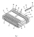
- Fig. 1 is a perspective view of the housing, sealing member and seal holder of the connector embodying the invention.
- Fig. 2 is a partly cut-away perspective view of a bus bar unit of the connector of Fig. 1.
- Fig. 3 is a perspective view of a cap of the connector of Fig. 1.
- Fig. 4 is a partly cut-away plan view of the connector in an assembled state.
- Fig. 5 is a partly cut-away plan view of the connector in which a bus bar unit is positioned at a temporary locking position.
- Fig. 6 is a sectional view on line II-II of Fig. 4 including terminals in the connector cavities (in broken lines), a lower bus bar unit fully installed, and an upper bus bar unit bearing on a lance.
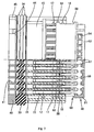
- Fig. 7 is the same sectional view as Fig. 6 with bus bar units in partially installed positions and the connector set on an assembly jig.
- Fig. 8 is the same sectional view as Fig. 7 but with both bus bar units moved to fully installed positions by means of the assembling jig.
- Fig. 9 is the same section view as Fig. 6, but with the upper bus bar unit prevented from arriving at its partially inserted position.
- Fig. 10 is the same section view as Fig. 6 but with both bus bar units fully installed.
-
- The connector embodying the present invention shown in Figs. 1 to 10 for electrically connecting a plurality of
terminals 20 in a predetermined connection pattern with abus bar 55 has ahousing 10, a plurality of theterminals 20, asealing member 30, aseal holder 40, twobus bar units 50, and acap 60. - The
housing 10 is made of a synthetic resinous material. Thehousing 10 hascavities 11 arranged in upper and lower rows and extending through thehousing 10 in a front-to-rear direction. In each of the upper and lower rows, thecavities 11 are arranged widthwise at regular intervals. The front half region of the upper-row cavities 11 and the lower-row cavities 11 are open at the upper and lower surfaces of thehousing 10, respectively. In each open portion, locking lances (i.e. locking members) 12 project forward in a cantilever manner. Between the upper and lower rows of thecavities 11 there is formed awide recess 13 for allowing the peripheral walls of thebus bar units 50 to penetrate. An upper surface wall and a lower surface wall of therecess 13 are partly cut away to allow communication with thecavities 11. - The
lance 12 retains and prevents the removal of theterminal 20 inserted into thecavity 11. In cooperation with acylindrical portion 53 of thebus bar unit 50 it is also used for detecting the degree of insertion of theterminal 20. Thelance 12 can be outwardly elastically displaced relative to an outer surface of thehousing 10. Before theterminal 20 is inserted into thecavity 11 or when the terminal is fully inserted therein, thelance 12 is undeformed, and an outer surface of the lance is flush with the outer surface of thehousing 10. In this state, a removal prevention projection formed at a front end of thelance 12 is engaged in alocking hole 24 of the terminal 20 (see lower bus bar unit of Fig. 6), thus preventing removal of theterminal 20. However, when theterminal 20 is not fully inserted, the removal prevention projection interferes with the outer surface of amating portion 21 of theterminal 20. As a result, thelance 12 is elastically displaced outward such that the outer surface is located outwardly from the outer surface of the housing 10 (see upper bus bar unit of Fig. 6). Therefore, when thebus bar unit 50 is installed on thehousing 10, thecylindrical portion 53 of thebus bar unit 50 collides with the front end of thelance 12. This prevents the completion of the bus bar unit-installing operation. - Each terminal 20 is made of a metal plate material punched into a predetermined configuration. The front half part of the terminal 20 is formed as a square pillar-shaped
mating portion 21 open forward and rearward. The rear half of the terminal 20 is formed as an electricwire connection portion 22 crimped to the core of anelectric wire 25. Aresilient contact piece 23 that contacts aconnection piece 57 of thebus bar 55 is formed inside themating portion 21. A lockinghole 24 which thelocking lance 12 of thehousing 10 engages is formed on a peripheral wall of themating portion 21. The terminal 20 is inserted into thecavity 11 of thehousing 10 by passing it through theseal member 30 and theseal holder 40 installed on thehousing 10 from the rear of thehousing 10. Immediately before the terminal 20 reaches its fully inserted position, thelance 12 interferes with the peripheral surface of themating portion 21. Therefore, thelance 12 flexes elastically outward from thehousing 10. When the terminal 20 reaches the fully inserted position, thelance 12 is elastically restored to its original state and is engaged in the lockinghole 24, thus preventing the terminal 20 from being removed from thecavity 11. The orientation of the terminals in the upper row ofcavities 11 is reversed relative to that of the terminals in the lower cavity row. - The sealing
member 30 is made of rubber, oval-shaped, and thick. The sealingmember 30 is installed on thehousing 10 by sandwiching it between the rear end surface of thehousing 10 and the front end surface of theseal holder 40. A plurality of sealingholes 31 open at the front and rear surfaces of the sealingmember 30 is formed coincident with thecavities 11 of thehousing 10. Each sealinghole 31 is circular. A lip portion of corrugated shape having three convexities is circumferentially formed on the inner peripheral surface of each sealinghole 31. The inner diameter of the lip portion is smaller than the outer diameter of the coating of thewire 25. When thewire 25 is in the sealinghole 31, the lip portion contacts the peripheral surface of thewire 25 elastically, thus sealing around thewire 25. - The peripheral edge of the sealing
member 30 is formed as a corrugated sealing edge. Alip portion 34 having three convexities approximately semi-circular in section extends circumferentially around the sealingmember 30. Thelip portion 34 contacts the inner peripheral surface of thecap 60 elastically, thus sealing between the sealingmember 30 and thecap 60. - The
seal holder 40 is made of a relatively rigid synthetic resin material. Similarly to the sealingmember 30, theseal holder 40 is oval-shaped and thick. Thelip portion 34 formed on the periphery of the sealingmember 30 is slightly larger than the periphery of theseal holder 40. A plurality ofterminal insertion openings 41 extend between the front and rear end surfaces of theseal holder 40 in correspondence to thecavities 11 and the sealing holes 31. Each terminal 20 is inserted into thecavity 11 through theterminal insertion opening 41. - Two locking
projections 44 are formed at each of both ends of upper and lower flat peripheral surfaces of theseal holder 40. The lockingprojections 44 engage thecap 60, thus hindering thecap 60 from being easily removed from thehousing 10, the sealingmember 30, and theseal holder 40. Anindex projection 45 is formed in each circular arc-shaped region located at right and left ends of the peripheral surface of theseal holder 40. Thus, each of a pair of theindex projections 45 is formed such that the inward side thereof is on a level higher than that of the outward side thereof. Theindex projection 45 serves as an index for checking the upper and lower sides of thehousing 10 when theterminal fixture 20 is inserted into thecavity 11. - The
bus bar unit 50 is composed of a holdingmember 51 made of a relatively rigid synthetic resin material and ametal bus bar 55 integrated with the holdingmember 51 by insert molding. The holdingmember 51 has a wide sheet-shaped holdingportion 52 and a flatcylindrical portion 53 projecting rearward (direction toward the housing 10) from the sheet-shaped holdingportion 52. Thebus bar 55 consists of a plurality ofconnection pieces 57 projecting in parallel with each other in the shape of a cantilever from an edge of a belt-shapedcarrier 56. Thebus bar 55 is held, with thecarrier 56 disposed along the sheet-shaped holdingportion 52 and withconnection pieces 57 facing thecylindrical portion 53. A punchedhole 54 is formed on the sheet-shaped holdingportion 52 in correspondence to the gap betweenadjacent connection pieces 57 projecting from thecarrier 56. In the process of producing thebus bar unit 50, a portion of thecarrier 56 facing each punchedhole 54 is punched with a punch and die in correspondence to a predetermined connection pattern. As a result, thecarrier 56 is divided (not shown) into a plurality of bus bars 55. Onebus bar 55 has at least threeconnection pieces 57. A plurality ofterminals 20 are connected by eachbus bar 55 through theconnection pieces 57. - Each
bus bar unit 50 is installed on thehousing 10 in a direction forward therefrom such that thecylindrical portion 53 covers the upper-row cavities 11 or the lower-row cavities 11. When thebus bar unit 50 has been installed on thehousing 10, theconnection pieces 57 are connected with theterminals 20. Connection patterns can be discriminated from each other by changing the color of the holdingmember 51 of thebus bar unit 50. The upper part of the holdingmember 51 and the lower part thereof are not symmetrical with each other. Thus, the requiredbus bar unit 50 can be installed on thehousing 10 in a correct direction, and a group of theterminal fixtures 20 can be connected in a correct pattern by checking colors and directions of the holdingmembers 51. - The
cap 60 is made of a relatively rigid synthetic resin material. Thecap 60 is oval-shaped in a front view and has a closed bottom. Lockingholes 61 to which the lockingprojections 44 of theseal holder 40 lock are formed at the edge of the open mouth of thecap 60. Thecap 60 is locked in the installed state by the engagement between the lockingprojections 44 and the locking holes 61.Relief portions 62 projecting outwardly are formed on the edge of the open mouth of thecap 60 to prevent thecap 60 from interfering with theindex projections 45 of theseal holder 40. The region of the inner peripheral surface of thecap 60 near the edge of its open mouth is formed as a sealingsurface 63 with which thelip portion 34 formed on the peripheral edge of the sealingmember 30 contacts elastically. - Guide grooves 58 (which are part of a temporary locking means or detent) extend in a front to rear direction at the right and left-hand sides of the
cylindrical portion 53 of eachbus bar unit 50. Front andrear locking projections 17 and 18 (which are also part of the temporary locking means or detent) corresponding to eachguide groove 58 are formed on thehousing 10. Eachbus bar unit 50 is held at a temporary locking position (i.e. partially installed position) by sandwiching a rear end portion of thecylindrical portion 53 between the lockingprojections cylindrical portion 53 and the proximal (rear) end of the guide groove 58 (see Fig. 5). Eachbus bar unit 50 is held at a normal installing position (i.e. fully installed position) by locking the front end of theguide groove 58 and the rear end thereof to the lockingprojections guide groove 58 sandwiching the lockingprojections bus bar units 50 are held at the normal installing position, theterminals 20 are electrically connected by the bus bars 55. As described above, during installation at eachbus bar unit 50 on thehousing 10, the temporary locking means allows thebus bar unit 50 to be held at the temporary locking position (see lower but bar unit of Fig. 6 and Fig. 7) which is located forward from the normal installing position (see Figs. 8 and 10) where the terminals are electrically connected. The temporary locking position is located rearwardly from the collision position at which alance 12 would collide with the respectivebus bar unit 50 if the lance were outwardly displaced from the outer surface of thehousing 10 e.g. due to an incomplete terminal insertion (see upper step of Fig. 6). In other words on installation eachbus bar unit 50 must pass the collision position before it arrives at the temporary locking position. Over the distance between the installation start position of thebus bar unit 50 and the temporary locking position, through the collision position between thelance 12 and thebus bar unit 50, thetab pieces 57 do not make contact with theterminals 20. - During assembly of the connector, an assembling
jig 70 is used. The assemblingjig 70 has the function of installing thebus bar units 50 on thehousing 10 and detecting the state of insertion of theterminals 20. As shown in Figs. 7 9, the assemblingjig 70 includes alever 72 which is supported at the right end of asubstrate 71 and can be pivoted between a waiting posture shown in Figs. 7 and 9 and an assembling posture shown in Fig. 8; a pressingmember 73 which is moved leftward in Figs. 7 - 9 in correspondence with the pivotal motion (counterclockwise in Figs. 7 - 9) of thelever 72 by the camming action of thelever 72; and astationary positioning member 74 located leftward in Figs. 7 - 9 from the pressingmember 73. A return spring (not shown) biases thelever 72 and the pressingmember 73 to the waiting position. The connector is dropped between the pressing member 73 (located at the waiting position) and the positioningmember 74, with thebus bar units 50 set at the temporary locking position. - The distance between the pressing
member 73 in the waiting position and the positioningmember 74 is equal to or a little longer than the distance between the front ends of thebus bar units 50 when the bus bar units are at the temporary locking position and the rear end of thehousing 10. Therefore, the connector cannot be set in thejig 70 when abus bar unit 50 has not reached the temporary locking position. This is because thebus bar unit 50 interferes with the upper surface of the pressingmember 73. - When the
lever 72 is pivoted from the waiting posture to the assembling posture after the connector has been set in thejig 70, the pressingmember 73 moves leftward and presses thebus bar units 50 from the temporary locking position to the normal assembling position. During the movement of thebus bar units 50, thetab pieces 57 of thebus bar units 50 contact theresilient contact pieces 23. Consequently, theterminals 20 are connected to each other. - The assembly procedure is as follows. Initially, the sealing
member 30 is sandwiched between theseal holder 40 and thehousing 10. At this time, a projection (not shown) formed on thehousing 10 is passed through the sealingmember 30 and the tip of the projection is locked to theseal holder 40. This locks theseal member 30 to thehousing 10, and the removal of theseal holder 40 is prevented. Then, theterminals 20 are inserted through theopenings 41 and theholes 31 into thecavities 11. - Thereafter, the
bus bar unit 50 is installed at the temporary locking position on thehousing 10, and thebus bar unit 50 is placed on the assemblingjig 70. Then, by operating thelever 72 of the assemblingjig 70, thebus bar unit 50 is pressed to the normal installing position from the temporary locking position. As a result, theterminals 20 are connected in a predetermined pattern. When the bus bar unit orunits 50 are in the normal installing position, the connector is removed from the assemblingjig 70. Finally, thecap 60 is installed on thehousing 10 in such a manner that thecap 60 covers thehousing 10 and thebus bar unit 50. - The
lip portion 34 formed on the periphery of the sealingmember 30 prevents water from penetrating into thecap 60 between the inner periphery of thecap 60 and the periphery of the sealingmember 30. Further, the lip portion of the sealinghole 31 contacts the periphery of thewire 25 closely, the inner periphery of the fit-in hole 32 contacts the periphery of the holding projection 14, and the inner periphery of the fit-in hole 33 contacts the periphery of the deformation prevention projection 15. Therefore, water can be prevented from penetrating into the sealingmember 30 from outside. - On installation of the
bus bar unit 50 on thehousing 10 when all theterminals 20 are fully inserted into theirrespective cavities 11, eachlance 12 is undeformed so that its outer surface is flush with the outer surface of thehousing 10. Accordingly, when thecylindrical portion 53 slides over the outer surface of thehousing 10 during bus bar unit-installation, thecylindrical portion 53 does not interfere with thelances 12. Thus, thebus bar unit 50 can be securely installed to the temporary locking position of the housing. When thebus bar unit 50 has been installed on thehousing 10 in the temporary locking position, thecylindrical portion 53 faces thelances 12 in such a manner that the inner surface of thecylindrical portion 53 presses downward on the outer surfaces of thelances 12. Thus, thelances 12 are prevented from being elastically displaced in a direction which would move them away from the terminals 20 (see the lower bus bar unit of Fig. 6). - On the other hand, if there is any terminal 20 inserted into the
cavity 11 in an incomplete or partially inserted state, thelance 12 is elastically displaced outward, and projects outward from the outer surface of thehousing 10. During installation of thebus bar unit 50 on thehousing 10, the front end of thecylindrical portion 53 then collides with the front end of the lance 12 (see upper bus bar unit of Fig. 6). As a result, the installation operator notices that the installation resistance is suddenly increased. In this manner, the operator can detect that a terminal is in the incomplete inserted state. - The operator suspends the installation of the
bus bar unit 50 on thehousing 10 when thecylindrical portion 53 has collided with thelance 12 and resumes the installation after inserting the terminal 20 into the normal position of thecavity 11. If the operator does not feel a sudden increase in the installation resistance, he proceeds to use the assemblingjig 70. If the operator feels the installation resistance, but forgets to re-insert of the terminal 20, the operator may attempt to continue with the installation. However, in this case, the connector cannot be set on the assemblingjig 70. This alerts the operator to the fact that thebus bar unit 50 has been not arrived at the temporary locking position and that one or some of theterminals 20 may have been incompletely inserted. The connector cannot be set on the assemblingjig 70 if thebus bar unit 50 has not reached the temporary locking position, even though all the terminals may have been inserted correctly. As is apparent from the foregoing description, if the connector cannot be set on the assemblingjig 70, incorrect assembly can be corrected by checking the installation position of thebus bar unit 50 and the inserted states of theterminals 20. - As described above, during installation of the
bus bar unit 50 on thehousing 10, in the range of positions of thebus bar unit 50 including the position of collision between thebus bar unit 50 and thelance 12 and up to and including the temporary locking position, thebus bar unit 50 is not subjected to an installation resistance caused by contact between thetab pieces 57 of thebus bar unit 50 and theterminal fittings 20. After the bus bar unit passes the temporary locking position, thetab pieces 57 start to contact theterminals 20. Accordingly, it is possible to discriminate between installation resistance on thebus bar unit 50 due to the collision between thelance 12 and thebus bar unit 50 and installation resistance that is caused by collision between theterminals 20 and thetab pieces 57. In this manner, it is possible reliably to detect the state of insertion of theterminals 20. - If incomplete insertion of any of the terminals is not noticed and it is attempted to set the connector in the assembling
jig 70, thebus bar unit 50 will be at the position of collision between thelance 12 thebus bar unit 50. Thus, it is impossible to set the connector in the assembling jig. In this manner, it is detected that one or some of the terminals are incompletely inserted. That is, a mechanism is provided for detecting the incomplete insertion of a terminal 20 both during the process of installing thebus bar unit 50 on thehousing 10 and during the operation of setting the connector on the assemblingjig 70. Thus, the incomplete insertion of the terminal 20 can be reliably detected. - The present invention is not limited to the embodiment described, but may be varied for example as described below.
- (1) In the embodiment, a connector of waterproof type has been described. But the present invention is applicable to a connector of non-waterproof type.
- (2) In the embodiment, incomplete insertion of the terminal is detectable during installation of the bus bar unit on the housing and during setting of the connector on the assembling jig. However, according to the present invention, it is possible to detect incomplete insertion of the terminal during installation of the bus bar unit on the housing without using the assembling jig.
-
Claims (6)
- A connector comprising:a housing (10) having a plurality of cavities (11), a plurality of respective resiliently deformable locking members (12), and a plurality of respective terminals (20), each terminal being inserted in the respective said cavity and having (a) a partially inserted position in which the terminal bears on the respective said locking member to deform the locking member so that the locking member is proud of a peripheral surface of the housing, and (b) a fully inserted position in which the locking member snap-fits to the terminal thereby locking the terminal in the cavity, anda bus bar holder (50) having a sleeve (53) and a plurality of bus bar tab pieces (57) which are accommodated in the sleeve, the sleeve being push-fitted over said peripheral surface via a partially installed position, at which the tab pieces do not contact the terminals, to a fully installed position, at which the tab pieces contact the terminals, whereby in the fully installed position the bus bar holder is installed to the housing with the terminals electrically connected to each other,each locking member being adapted so that when said terminal is in the partially inserted position with the respective said locking member proud of said peripheral surface and an attempt is made to push-fit the sleeve to said partially installed position, the sleeve bears on the locking member to prevent the sleeve arriving at said partially installed position,and the connector further comprising a detent for detaining the bus bar holder at said partially installed position.
- A connector according to claim 1, wherein the detent comprises an elongate recess aligned with the push-fit direction of the sleeve and terminated at one end by an end member, and first and second projections which on push-fitting are displaced relative to the recess, whereby in the partially installed position of the sleeve the end member is held between the first and second projections so that the second projection is received in the recess, and in the fully installed position of the sleeve both the first and second projections are received in the recess.
- A connector according to claim 2, wherein the recess is formed in the sleeve and the projections are formed on the housing facing the sleeve.
- A connector according to claim 3, wherein the end member comprises a leading edge portion of the sleeve.
- A connector according to any one of claims 1 to 4, having two detents at opposite sides of the connector.
- An assembly jig (70) for setting thereon a connector of any one of claims 1 to 5 and for assembling the connector by push-fitting the sleeve of the connector from said partially installed position to said fully installed position,the jig being sized so that when the sleeve of the connector is prevented from arriving at said partially installed position the connector is prevented from being set on the jig, whereas when the sleeve of the connector is at said partially installed position the connector is settable on the jig.
Applications Claiming Priority (8)
| Application Number | Priority Date | Filing Date | Title |
|---|---|---|---|
| JP11105919A JP2000299156A (en) | 1999-04-13 | 1999-04-13 | Joint connector |
| JP10591999 | 1999-04-13 | ||
| JP10592099 | 1999-04-13 | ||
| JP10592099A JP3362698B2 (en) | 1999-04-13 | 1999-04-13 | Waterproof joint connector |
| JP11847999A JP3367463B2 (en) | 1999-04-26 | 1999-04-26 | Joint connector |
| JP11847999 | 1999-04-26 | ||
| JP15264599A JP3365350B2 (en) | 1999-05-31 | 1999-05-31 | Joint connector and jig for assembling joint connector |
| JP15264599 | 1999-05-31 |
Publications (3)
| Publication Number | Publication Date |
|---|---|
| EP1045483A2 true EP1045483A2 (en) | 2000-10-18 |
| EP1045483A3 EP1045483A3 (en) | 2002-06-12 |
| EP1045483B1 EP1045483B1 (en) | 2007-08-01 |
Family
ID=27469374
Family Applications (1)
| Application Number | Title | Priority Date | Filing Date |
|---|---|---|---|
| EP00303001A Expired - Lifetime EP1045483B1 (en) | 1999-04-13 | 2000-04-10 | Combination of connector and assembly jig |
Country Status (3)
| Country | Link |
|---|---|
| US (1) | US6186806B1 (en) |
| EP (1) | EP1045483B1 (en) |
| DE (1) | DE60035730T2 (en) |
Cited By (3)
| Publication number | Priority date | Publication date | Assignee | Title |
|---|---|---|---|---|
| EP1659660A1 (en) * | 2004-11-17 | 2006-05-24 | Delphi Technologies, Inc. | Electrical connector |
| EP1701417A1 (en) * | 2005-03-11 | 2006-09-13 | Sumitomo Wiring Systems, Ltd. | A joint connector and method of assembling it |
| CN102684040A (en) * | 2012-05-15 | 2012-09-19 | 成都阿尔刚雷科技有限公司 | Anti-creeping method and anti-creeping connecting device |
Families Citing this family (16)
| Publication number | Priority date | Publication date | Assignee | Title |
|---|---|---|---|---|
| JP4080132B2 (en) * | 2000-03-15 | 2008-04-23 | 新神戸電機株式会社 | Assembled battery |
| US20040253864A1 (en) * | 2001-12-21 | 2004-12-16 | Lear Corporation | Watertight connector-module assembly |
| ES1051490Y (en) * | 2001-12-21 | 2002-12-01 | Lear Automotive Eeds Spain | SEAL MODULE-CONNECTOR ASSEMBLY. |
| JP4259453B2 (en) * | 2004-10-29 | 2009-04-30 | 住友電装株式会社 | Waterproof connector |
| US7867001B2 (en) * | 2006-12-28 | 2011-01-11 | Mitsubishi Cable Industries, Ltd. | Connection member and harness connector |
| EP2279539A1 (en) * | 2008-05-15 | 2011-02-02 | Johnson Controls Saft Advanced Power Solutions LLC | Battery system |
| US8164011B1 (en) * | 2009-03-13 | 2012-04-24 | Sonosite, Inc. | Medical device manual transducer switch |
| JP2011076974A (en) | 2009-10-01 | 2011-04-14 | Yazaki Corp | Connector |
| BR112012023656A2 (en) * | 2010-03-25 | 2017-10-10 | Yazaki Corp | connector and method for connector bus pattern identification |
| JP2012174431A (en) * | 2011-02-18 | 2012-09-10 | Yazaki Corp | Joint connector and terminal semi-insertion inspection method |
| JP5778509B2 (en) * | 2011-07-19 | 2015-09-16 | 矢崎総業株式会社 | Joint connector |
| JP5704025B2 (en) * | 2011-09-08 | 2015-04-22 | 株式会社オートネットワーク技術研究所 | Joint connector |
| JP6024611B2 (en) | 2013-07-17 | 2016-11-16 | 住友電装株式会社 | connector |
| JP6276113B2 (en) * | 2014-06-02 | 2018-02-07 | ホシデン株式会社 | connector |
| JP5835434B1 (en) * | 2014-07-31 | 2015-12-24 | 第一精工株式会社 | Waterproof connector |
| JP6311597B2 (en) * | 2014-12-25 | 2018-04-18 | 住友電装株式会社 | Connector housing |
Citations (5)
| Publication number | Priority date | Publication date | Assignee | Title |
|---|---|---|---|---|
| US5201667A (en) * | 1990-06-27 | 1993-04-13 | Yazaki Corporation | Branch circuit structure |
| EP0654856A2 (en) * | 1993-11-18 | 1995-05-24 | Sumitomo Wiring Systems, Ltd. | Connector examination and correction devices and methods for examining and correcting same |
| EP0750369A2 (en) * | 1995-06-19 | 1996-12-27 | Sumitomo Wiring Systems, Ltd. | Connector and cover therefor |
| JPH09106847A (en) * | 1996-01-26 | 1997-04-22 | Sumitomo Wiring Syst Ltd | Connector |
| US5655928A (en) * | 1994-10-19 | 1997-08-12 | Yazaki Corporation | Incomplete engagement detecting structure in a connector |
Family Cites Families (4)
| Publication number | Priority date | Publication date | Assignee | Title |
|---|---|---|---|---|
| JPH0261082U (en) | 1988-10-28 | 1990-05-07 | ||
| JP2563707Y2 (en) | 1990-08-07 | 1998-02-25 | 矢崎総業株式会社 | connector |
| US5788519A (en) * | 1995-05-02 | 1998-08-04 | Yazaki Corporation | Waterproof grounding connector and method of assembling same |
| JP3239330B2 (en) | 1996-01-31 | 2001-12-17 | 矢崎総業株式会社 | Manufacturing method of joint connector |
-
2000
- 2000-04-10 US US09/545,831 patent/US6186806B1/en not_active Expired - Lifetime
- 2000-04-10 DE DE60035730T patent/DE60035730T2/en not_active Expired - Lifetime
- 2000-04-10 EP EP00303001A patent/EP1045483B1/en not_active Expired - Lifetime
Patent Citations (5)
| Publication number | Priority date | Publication date | Assignee | Title |
|---|---|---|---|---|
| US5201667A (en) * | 1990-06-27 | 1993-04-13 | Yazaki Corporation | Branch circuit structure |
| EP0654856A2 (en) * | 1993-11-18 | 1995-05-24 | Sumitomo Wiring Systems, Ltd. | Connector examination and correction devices and methods for examining and correcting same |
| US5655928A (en) * | 1994-10-19 | 1997-08-12 | Yazaki Corporation | Incomplete engagement detecting structure in a connector |
| EP0750369A2 (en) * | 1995-06-19 | 1996-12-27 | Sumitomo Wiring Systems, Ltd. | Connector and cover therefor |
| JPH09106847A (en) * | 1996-01-26 | 1997-04-22 | Sumitomo Wiring Syst Ltd | Connector |
Non-Patent Citations (1)
| Title |
|---|
| PATENT ABSTRACTS OF JAPAN vol. 1997, no. 08, 29 August 1997 (1997-08-29) & JP 09 106847 A (SUMITOMO WIRING SYST LTD), 22 April 1997 (1997-04-22) * |
Cited By (4)
| Publication number | Priority date | Publication date | Assignee | Title |
|---|---|---|---|---|
| EP1659660A1 (en) * | 2004-11-17 | 2006-05-24 | Delphi Technologies, Inc. | Electrical connector |
| EP1701417A1 (en) * | 2005-03-11 | 2006-09-13 | Sumitomo Wiring Systems, Ltd. | A joint connector and method of assembling it |
| CN102684040A (en) * | 2012-05-15 | 2012-09-19 | 成都阿尔刚雷科技有限公司 | Anti-creeping method and anti-creeping connecting device |
| CN102684040B (en) * | 2012-05-15 | 2015-05-13 | 成都阿尔刚雷科技有限公司 | Anti-creeping method and anti-creeping connecting device |
Also Published As
| Publication number | Publication date |
|---|---|
| EP1045483B1 (en) | 2007-08-01 |
| US6186806B1 (en) | 2001-02-13 |
| DE60035730T2 (en) | 2008-04-30 |
| DE60035730D1 (en) | 2007-09-13 |
| EP1045483A3 (en) | 2002-06-12 |
Similar Documents
| Publication | Publication Date | Title |
|---|---|---|
| EP1045483B1 (en) | Combination of connector and assembly jig | |
| EP1889332B1 (en) | Connector assembly with terminal position assurance device | |
| EP2249440B1 (en) | A connector, connector assembly and connection method | |
| EP1045481B1 (en) | Waterproof connector for electrical terminals | |
| US5769650A (en) | Connector and cover therefor | |
| CA1286379C (en) | Connector assembly | |
| JP3672229B2 (en) | Holder removal prevention connector | |
| EP3955394B1 (en) | Connector | |
| EP0727844B1 (en) | Electrical connector | |
| US5823807A (en) | Connector assembly with mechanism for confirmation of fitting of connector housing and method of attaching connector housing | |
| EP1045482B1 (en) | Connector | |
| GB2249438A (en) | Detecting proper coupling of two-part connector | |
| EP1033788B1 (en) | Connector with secondary locking | |
| EP0955696A1 (en) | Electrical connector with terminal position assurance device | |
| EP1073153B1 (en) | Connector | |
| US5620346A (en) | Connector and connector testing apparatus | |
| EP1528634B1 (en) | A divided connector and a method of assembling it | |
| EP1091451B1 (en) | Connector | |
| US7172459B2 (en) | Electrical connector housing, electrical connector, and connector assembly | |
| US6179660B1 (en) | Connector apparatus | |
| US20030162413A1 (en) | Split-type connector and connector assembly | |
| EP1049209B1 (en) | Connector having a terminal retainer | |
| EP1094559B1 (en) | Electrical connector having a terminal retainer | |
| US5647778A (en) | Electrical connector | |
| US6422894B1 (en) | Connector fitting detection construction |
Legal Events
| Date | Code | Title | Description |
|---|---|---|---|
| PUAI | Public reference made under article 153(3) epc to a published international application that has entered the european phase |
Free format text: ORIGINAL CODE: 0009012 |
|
| 17P | Request for examination filed |
Effective date: 20000502 |
|
| AK | Designated contracting states |
Kind code of ref document: A2 Designated state(s): AT BE CH CY DE DK ES FI FR GB GR IE IT LI LU MC NL PT SE |
|
| AX | Request for extension of the european patent |
Free format text: AL;LT;LV;MK;RO;SI |
|
| PUAL | Search report despatched |
Free format text: ORIGINAL CODE: 0009013 |
|
| AK | Designated contracting states |
Kind code of ref document: A3 Designated state(s): AT BE CH CY DE DK ES FI FR GB GR IE IT LI LU MC NL PT SE |
|
| AX | Request for extension of the european patent |
Free format text: AL;LT;LV;MK;RO;SI |
|
| RIC1 | Information provided on ipc code assigned before grant |
Free format text: 7H 01R 13/629 A, 7H 01R 13/422 B, 7H 01R 13/703 B, 7H 01R 31/08 B, 7H 01R 13/424 B |
|
| AKX | Designation fees paid |
Designated state(s): DE GB |
|
| GRAP | Despatch of communication of intention to grant a patent |
Free format text: ORIGINAL CODE: EPIDOSNIGR1 |
|
| RTI1 | Title (correction) |
Free format text: COMBINATION OF CONNECTOR AND ASSEMBLY JIG |
|
| GRAS | Grant fee paid |
Free format text: ORIGINAL CODE: EPIDOSNIGR3 |
|
| GRAA | (expected) grant |
Free format text: ORIGINAL CODE: 0009210 |
|
| AK | Designated contracting states |
Kind code of ref document: B1 Designated state(s): DE GB |
|
| REG | Reference to a national code |
Ref country code: GB Ref legal event code: FG4D |
|
| REF | Corresponds to: |
Ref document number: 60035730 Country of ref document: DE Date of ref document: 20070913 Kind code of ref document: P |
|
| PLBE | No opposition filed within time limit |
Free format text: ORIGINAL CODE: 0009261 |
|
| STAA | Information on the status of an ep patent application or granted ep patent |
Free format text: STATUS: NO OPPOSITION FILED WITHIN TIME LIMIT |
|
| 26N | No opposition filed |
Effective date: 20080506 |
|
| PGFP | Annual fee paid to national office [announced via postgrant information from national office to epo] |
Ref country code: GB Payment date: 20140409 Year of fee payment: 15 |
|
| GBPC | Gb: european patent ceased through non-payment of renewal fee |
Effective date: 20150410 |
|
| PG25 | Lapsed in a contracting state [announced via postgrant information from national office to epo] |
Ref country code: GB Free format text: LAPSE BECAUSE OF NON-PAYMENT OF DUE FEES Effective date: 20150410 |
|
| REG | Reference to a national code |
Ref country code: DE Ref legal event code: R084 Ref document number: 60035730 Country of ref document: DE |
|
| PGFP | Annual fee paid to national office [announced via postgrant information from national office to epo] |
Ref country code: DE Payment date: 20190326 Year of fee payment: 20 |
|
| REG | Reference to a national code |
Ref country code: DE Ref legal event code: R071 Ref document number: 60035730 Country of ref document: DE |