EP1048317A2 - Systems for positioning therapy delivery elements within a spinal cord or a brain - Google Patents
Systems for positioning therapy delivery elements within a spinal cord or a brain Download PDFInfo
- Publication number
- EP1048317A2 EP1048317A2 EP00107043A EP00107043A EP1048317A2 EP 1048317 A2 EP1048317 A2 EP 1048317A2 EP 00107043 A EP00107043 A EP 00107043A EP 00107043 A EP00107043 A EP 00107043A EP 1048317 A2 EP1048317 A2 EP 1048317A2
- Authority
- EP
- European Patent Office
- Prior art keywords
- lead
- therapy delivery
- therapy
- targeted tissue
- delivery elements
- Prior art date
- Legal status (The legal status is an assumption and is not a legal conclusion. Google has not performed a legal analysis and makes no representation as to the accuracy of the status listed.)
- Withdrawn
Links
Images


Classifications
-
- A—HUMAN NECESSITIES
- A61—MEDICAL OR VETERINARY SCIENCE; HYGIENE
- A61M—DEVICES FOR INTRODUCING MEDIA INTO, OR ONTO, THE BODY; DEVICES FOR TRANSDUCING BODY MEDIA OR FOR TAKING MEDIA FROM THE BODY; DEVICES FOR PRODUCING OR ENDING SLEEP OR STUPOR
- A61M5/00—Devices for bringing media into the body in a subcutaneous, intra-vascular or intramuscular way; Accessories therefor, e.g. filling or cleaning devices, arm-rests
- A61M5/14—Infusion devices, e.g. infusing by gravity; Blood infusion; Accessories therefor
- A61M5/142—Pressure infusion, e.g. using pumps
- A61M5/14244—Pressure infusion, e.g. using pumps adapted to be carried by the patient, e.g. portable on the body
- A61M5/14276—Pressure infusion, e.g. using pumps adapted to be carried by the patient, e.g. portable on the body specially adapted for implantation
-
- A—HUMAN NECESSITIES
- A61—MEDICAL OR VETERINARY SCIENCE; HYGIENE
- A61N—ELECTROTHERAPY; MAGNETOTHERAPY; RADIATION THERAPY; ULTRASOUND THERAPY
- A61N1/00—Electrotherapy; Circuits therefor
- A61N1/02—Details
- A61N1/04—Electrodes
- A61N1/05—Electrodes for implantation or insertion into the body, e.g. heart electrode
- A61N1/0526—Head electrodes
- A61N1/0529—Electrodes for brain stimulation
- A61N1/0531—Brain cortex electrodes
-
- A—HUMAN NECESSITIES
- A61—MEDICAL OR VETERINARY SCIENCE; HYGIENE
- A61N—ELECTROTHERAPY; MAGNETOTHERAPY; RADIATION THERAPY; ULTRASOUND THERAPY
- A61N1/00—Electrotherapy; Circuits therefor
- A61N1/02—Details
- A61N1/04—Electrodes
- A61N1/05—Electrodes for implantation or insertion into the body, e.g. heart electrode
- A61N1/0526—Head electrodes
- A61N1/0529—Electrodes for brain stimulation
- A61N1/0534—Electrodes for deep brain stimulation
-
- A—HUMAN NECESSITIES
- A61—MEDICAL OR VETERINARY SCIENCE; HYGIENE
- A61N—ELECTROTHERAPY; MAGNETOTHERAPY; RADIATION THERAPY; ULTRASOUND THERAPY
- A61N1/00—Electrotherapy; Circuits therefor
- A61N1/02—Details
- A61N1/04—Electrodes
- A61N1/05—Electrodes for implantation or insertion into the body, e.g. heart electrode
- A61N1/0526—Head electrodes
- A61N1/0529—Electrodes for brain stimulation
- A61N1/0539—Anchoring of brain electrode systems, e.g. within burr hole
-
- A—HUMAN NECESSITIES
- A61—MEDICAL OR VETERINARY SCIENCE; HYGIENE
- A61N—ELECTROTHERAPY; MAGNETOTHERAPY; RADIATION THERAPY; ULTRASOUND THERAPY
- A61N1/00—Electrotherapy; Circuits therefor
- A61N1/02—Details
- A61N1/04—Electrodes
- A61N1/05—Electrodes for implantation or insertion into the body, e.g. heart electrode
- A61N1/0551—Spinal or peripheral nerve electrodes
- A61N1/0558—Anchoring or fixation means therefor
-
- A—HUMAN NECESSITIES
- A61—MEDICAL OR VETERINARY SCIENCE; HYGIENE
- A61N—ELECTROTHERAPY; MAGNETOTHERAPY; RADIATION THERAPY; ULTRASOUND THERAPY
- A61N1/00—Electrotherapy; Circuits therefor
- A61N1/18—Applying electric currents by contact electrodes
- A61N1/32—Applying electric currents by contact electrodes alternating or intermittent currents
- A61N1/36—Applying electric currents by contact electrodes alternating or intermittent currents for stimulation
- A61N1/3605—Implantable neurostimulators for stimulating central or peripheral nerve system
- A61N1/3606—Implantable neurostimulators for stimulating central or peripheral nerve system adapted for a particular treatment
- A61N1/36071—Pain
-
- A—HUMAN NECESSITIES
- A61—MEDICAL OR VETERINARY SCIENCE; HYGIENE
- A61M—DEVICES FOR INTRODUCING MEDIA INTO, OR ONTO, THE BODY; DEVICES FOR TRANSDUCING BODY MEDIA OR FOR TAKING MEDIA FROM THE BODY; DEVICES FOR PRODUCING OR ENDING SLEEP OR STUPOR
- A61M2209/00—Ancillary equipment
- A61M2209/04—Tools for specific apparatus
- A61M2209/045—Tools for specific apparatus for filling, e.g. for filling reservoirs
-
- A—HUMAN NECESSITIES
- A61—MEDICAL OR VETERINARY SCIENCE; HYGIENE
- A61M—DEVICES FOR INTRODUCING MEDIA INTO, OR ONTO, THE BODY; DEVICES FOR TRANSDUCING BODY MEDIA OR FOR TAKING MEDIA FROM THE BODY; DEVICES FOR PRODUCING OR ENDING SLEEP OR STUPOR
- A61M2210/00—Anatomical parts of the body
- A61M2210/06—Head
- A61M2210/0693—Brain, cerebrum
-
- A—HUMAN NECESSITIES
- A61—MEDICAL OR VETERINARY SCIENCE; HYGIENE
- A61M—DEVICES FOR INTRODUCING MEDIA INTO, OR ONTO, THE BODY; DEVICES FOR TRANSDUCING BODY MEDIA OR FOR TAKING MEDIA FROM THE BODY; DEVICES FOR PRODUCING OR ENDING SLEEP OR STUPOR
- A61M2210/00—Anatomical parts of the body
- A61M2210/10—Trunk
- A61M2210/1003—Spinal column
-
- A—HUMAN NECESSITIES
- A61—MEDICAL OR VETERINARY SCIENCE; HYGIENE
- A61M—DEVICES FOR INTRODUCING MEDIA INTO, OR ONTO, THE BODY; DEVICES FOR TRANSDUCING BODY MEDIA OR FOR TAKING MEDIA FROM THE BODY; DEVICES FOR PRODUCING OR ENDING SLEEP OR STUPOR
- A61M5/00—Devices for bringing media into the body in a subcutaneous, intra-vascular or intramuscular way; Accessories therefor, e.g. filling or cleaning devices, arm-rests
- A61M5/14—Infusion devices, e.g. infusing by gravity; Blood infusion; Accessories therefor
- A61M5/168—Means for controlling media flow to the body or for metering media to the body, e.g. drip meters, counters ; Monitoring media flow to the body
- A61M5/172—Means for controlling media flow to the body or for metering media to the body, e.g. drip meters, counters ; Monitoring media flow to the body electrical or electronic
- A61M5/1723—Means for controlling media flow to the body or for metering media to the body, e.g. drip meters, counters ; Monitoring media flow to the body electrical or electronic using feedback of body parameters, e.g. blood-sugar, pressure
-
- A—HUMAN NECESSITIES
- A61—MEDICAL OR VETERINARY SCIENCE; HYGIENE
- A61N—ELECTROTHERAPY; MAGNETOTHERAPY; RADIATION THERAPY; ULTRASOUND THERAPY
- A61N1/00—Electrotherapy; Circuits therefor
- A61N1/02—Details
- A61N1/04—Electrodes
- A61N1/05—Electrodes for implantation or insertion into the body, e.g. heart electrode
- A61N1/0551—Spinal or peripheral nerve electrodes
- A61N1/0553—Paddle shaped electrodes, e.g. for laminotomy
-
- A—HUMAN NECESSITIES
- A61—MEDICAL OR VETERINARY SCIENCE; HYGIENE
- A61N—ELECTROTHERAPY; MAGNETOTHERAPY; RADIATION THERAPY; ULTRASOUND THERAPY
- A61N1/00—Electrotherapy; Circuits therefor
- A61N1/02—Details
- A61N1/04—Electrodes
- A61N1/05—Electrodes for implantation or insertion into the body, e.g. heart electrode
- A61N1/056—Transvascular endocardial electrode systems
Definitions
- the present invention relates to stimulation or drug delivery systems, and more particularly relates to systems for positioning the treatment therapy elements, such as electrodes or catheters, to provide more effective treatment therapy.
- an electrical lead having one or more electrodes is implanted near a specific site in the brain or spinal cord of a patient.
- the lead is coupled to a signal generator which delivers electrical energy through the electrodes to nearby neurons and neural tissue.
- the electrical energy delivered through the electrodes creates an electrical field causing excitation of the nearby neurons to directly or indirectly treat the pain or neurological disorder.
- the lead may migrate such that the targeted tissue is outside of the effective steerable treatment range of the lead. Additionally, for some treatment applications, the lead just cannot be placed optimally to provide the desired treatment therapy. For example, in the case of treatment of lower back pain, electrical stimulation may be provided at the middle thoracic vertebral segments, T6-T9. With currently available systems, this often fails mostly due to the great thickness of the cerebral spinal fluid (CSF) layer.
- CSF cerebral spinal fluid
- the steerable electric field is limited by the location of the electrodes. If the electrodes move outside of the desired treatment area or if the desired stimulation area is different due to histological changes or disease migration, the desired treatment area may not be reached even by these steerable electrodes. Further, even if these steerable electrodes may be able to stimulate the desired neural tissue, the distance from the electrodes to the tissue may be too large such that it would require greater electrical power to provide the desired therapy. It has been shown that only a fraction of the current from modern stimulation devices gets to the neurons of interest. See W.A. Wesselink et al. "Analysis of Current Density and Related Parameters in Spinal Cord Stimulation," IEEE Transactions on Rehabilitation Engineering, Vol. 6, pp. 200-207 (1998). This not only more rapidly depletes the energy reserve, but it also may stimulate undesired neural tissue areas thereby creating undesired side effects such as pain, motor affects or discomfort to the patient.
- the present invention overcomes the above-noted and other shortcomings of known electrical stimulation and drug delivery techniques.
- the present invention provides a system for providing treatment therapy to targeted tissue comprising in combination:
- the position may be adjusted laterally in any number of directions relative to the lead or toward or away from the excitable tissue of interest. Any number of position control mechanisms may be incorporated to selectively adjust the position of the therapy delivery elements. Also, a position controller such as a microprocessor may be utilized to operate the position control mechanism to position the therapy delivery elements.
- an implantable lead for providing therapy to a body comprising:
- a system for providing neurostimulation therapy to targeted tissue comprising in combination:
- an implantable paddle-like lead for providing treatment therapy to targeted tissue of a body comprising:
- an implantable paddle-like lead for providing treatment therapy to targeted tissue of a body comprising:
- an implantable paddle-like lead for providing treatment therapy to targeted tissue of a body comprising:
- an implantable paddle-like lead for providing treatment therapy to targeted tissue of a body comprising:
- one or more therapy delivery elements may be placed within the cranial or vertebral bone of the patient so as to maintain the therapy delivery elements in a fixed position relative to the targeted neural tissue.
- the therapy delivery elements may thereafter be adjusted with a position control mechanism and/or a position controller to improve the desired treatment therapy.
- therapy delivery elements may be positioned to provide treatment therapy such as electrical stimulation and/or drug infusion to a precise target. Additionally, the present invention accounts for the problems associated with lead migration, histological changes, neural plasticity or disease progression.
- the present invention may incorporate a closed-loop system which may automatically adjust (1) the positioning of the therapy delivery elements in response to a sensed condition of the body such as a response to the treatment therapy; and/or (2) the treatment therapy parameters in response to a sensed symptom or an important related symptom indicative of the extent of the disorder being treated.
- a closed-loop system which may automatically adjust (1) the positioning of the therapy delivery elements in response to a sensed condition of the body such as a response to the treatment therapy; and/or (2) the treatment therapy parameters in response to a sensed symptom or an important related symptom indicative of the extent of the disorder being treated.
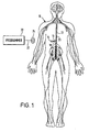
- FIG. 1 depicts a neurostimulation therapy delivery device 14 in accordance with an embodiment of the present invention.
- Therapy delivery device 14 made in accordance with the preferred embodiment is preferably implanted below the skin of a patient or, alternatively, may be an external device. Therapy delivery device 14 may be implanted as shown in Figure 1, in the abdomen or any other portion of the body 10.
- One or more leads 23 are positioned to stimulate a specific site in a spinal cord 12.
- Therapy delivery device 14 may take the form of a modified signal generator Model 7424 manufactured by Medtronic, Inc. under the trademark Itrel II®. Lead 23 may take the form of any of the leads sold with the Model 7424, for stimulating a spinal cord, and is coupled to therapy delivery device 14 by one or more conventional conductors 16 and 18.
- Lead 23 may include a paddle lead, a lead having one or more therapy delivery devices such as stimulation electrodes and/or catheters, or a combination catheter/lead capable of providing electrical stimulation and drug delivery. Lead 23 may also have recording electrodes. Exemplary embodiments of lead 23 incorporating the principles of the present invention are shown in the figures of the present application and discussed herein.
- the distal end of lead 23 terminates in one or more therapy delivery elements such as stimulation electrodes generally implanted into or near a selected portion of the spinal cord by conventional surgical techniques.
- the location of the electrodes is determined by the type of treatment that is desired. Any number of electrodes may be used for various applications.
- Each of the electrodes are preferably individually connected to therapy delivery device 14 through lead 23 and conductors 16 and 18.
- Lead 23 is surgically implanted either by a laminotomy or by a percutaneous needle.
- Therapy delivery device or signal generator 14 may be programmed to provide a predetermined stimulation dosage in terms of pulse amplitude, pulse width, pulse frequency, or duty cycle.
- a programmer 20 may be utilized to provide stimulation parameters to therapy delivery device 14 via telemetry.
- Programmer is coupled to an antenna 24 via conductor 22.
- the system may optionally include one or more sensors to provide closed-loop feedback control of the treatment therapy and/or electrode positioning.
- One or more sensors are attached to or implanted into a portion of a patient's body suitable for detecting a physical and/or chemical symptom or an important related symptom of the body.
- the feedback aspect of the present invention is discussed in further detail herein.
- SCS spinal cord stimulation
- DBS Deep Brain Stimulation
- the invention finds utility in applications other than SCS procedures, including other applications such as Peripheral Nerve or Ganglia Stimulation, Intra-Spinal Stimulation, Sacral Root Stimulation, or Intraventricular Cerebral Stimulation.
- the invention finds applicability to SCS procedures where the lead is placed in the intrathecal or subdural space.
- the present invention may also be utilized to provide stimulation of various muscles of the body such as the cardiac muscle.
- the invention also finds utility to drug therapy where electrical components are replaced with conduits and catheters for conducting drug material to the therapy site. In this case, especially, the lead may be placed in the intrathecal or subdural space.
- FIG. 2 is a cross-sectional view of spinal cord 12 at spinal bone level T-6 having an implanted lead 23A in accordance with a preferred embodiment of the present invention.
- Spinal cord 12 generally includes white matter 31, grey matter 33, and a surrounding dural sack 30.
- lead 23A is implanted in the epidural space outside of dural sack 30, but may alternatively be implanted in intrathecal spinal space or subcortically beneath dura 30.
- Lead 23A has a curved shape to match the shape of dura 30. The curvature may be matched to each spinal level or may be a general shape to approximately match all levels of spinal cord.
- lead 23A may be flat such that it "grips" the vertebral bone on its dorsal edges and is less prone to migration or rotation.
- Lead 23A has a dorsal side 125 away from spinal cord 12 and a ventral side 120 facing spinal cord 12.
- Figures 2-4 show the average width, height and spacing of tissue components at vertebral bone level T6.
- the dashed lines in these figures indicate distances of one standard deviation from the mean. See J. Holsheimer et al., "MR Assessment of the Normal Position of the Spinal Cord in the Spinal Cannal," Am. J. Neuroradiology, Vol. 15, pp. 951-959 (1994).
- lead 23A has two lateral electrode contacts 31 and 32 at opposite ends of lead 23A and a central electrode contact 33 in the central portion of lead 23A.
- Lateral and central electrodes 31-33 may be anodes, cathodes or nonactive. Alternatively, any one or more of lateral and central electrodes 31-33 may be recording electrodes or drug delivery ports.
- Lead 23A is preferably able to control the dorsal cerebral spinal fluid (CSF) width, even though it is placed outside of dura.
- lead 23A includes a position control mechanism capable of adjusting the position of one or more of the lateral or central electrodes 31-33. As shown, central electrode 33 is at a maximal distance dorsally from spinal cord 12.
- a position control mechanism may adjust the distance between central electrode 33 and the spinal cord 12.
- the position control mechanism is in the form of a cavity 34 within lead 23A which is able to expand and fill with fluid (controlled by a pump (not shown)) or other matter in the epidural space to reduce the separation between central electrode 33 and spinal cord 12.
- a pump (not shown) may be powered by signal generator 14 that also provides the stimulation energy for the electrodes at lateral and central electrodes 31-33 and a signal for controlling the position control mechanism.
- position control mechanism may be adjusted using external means and power such as a magnetic signal, a percutaneous needle or bulb on another component that can be pushed.
- central electrode 33 may be positioned such that the targeted neural tissue is stimulated with optimal efficacy and minimal side effects.
- the position control mechanism may take any number of embodiments for allowing movement of the electrodes and holding the electrodes in position.
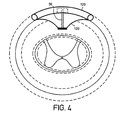
- Figure 3 illustrates a position control mechanism having metal bellows 35
- Figure 4 illustrates a position control mechanism having a piston 36.
- the bellows 35 of Figure 3 may alternatively be a threaded rod.
- a spring may be added to return the electrode to a less extended position.
- the position control mechanism may control all or a selective group of electrodes.
- one position control mechanism may control a longitudinal or transverse row of electrodes.
- each electrode to be adjusted may have its own individual position control mechanism.
- the position control mechanism of the above embodiments is preferably controlled by a position controller which is discussed in further detail herein.
- the position control mechanism is preferably adjustable such that it does not unduly depress neural tissue or hinder blood flow.
- Sensing feedback may be utilized, for example by a mechanical measure within a lead or an ultrasound or other sensor to give information about the distance. Sensing feedback may also be utilized to automatically adjust the positioning of the electrodes to provide optimum treatment therapy. Sensing feedback is discussed in further detail herein.
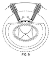
- Figures 5-9 disclose another group of embodiments of the present invention where electrodes are anchored to vertebral bones of the spinal cord.
- the electrodes may be implanted in the cortical bone of the skull. Electrodes may be positioned by drilling one or more holes at preselected locations in the bone. Leads having one or more electrodes may then be passed through the holes and positioned inside the vertebral canal/skull at optimal locations or distances from the target neural tissue. Electrodes may then be selectively adjusted in position after the implant. The depth of the electrodes may then be adjusted to provide the optimal stimulation therapy.
- an electrode 40 at the end of a threaded housing 43 is provided by drilling housing 43 into bone 42 surrounding spinal cord 12.
- bone 42 is preferably the dorsal aspect of vertebral bone.
- the lead 23B is coupled to electrode 40 and extends out through a top portion 41 of threaded housing 43.
- Figures 5B-D illustrate exemplary embodiments of the top portion of housing 41 to allow for engagement of various turning devices.
- Figure 5B depicts a cavity 45 to provide engagement of a screwdriver-like device to turn housing 43 to adjust position of electrode 40 relative to spinal cord 12.
- Figure 5C depicts a similar device but providing engagement of a slotted screwdriver-like device.
- Figure 5D depicts a hexagonal cavity 47 for engagement of a hexagonal wrench-like device or percutaneous needle.
- Housing 43 preferably is threaded with a high pitch so that a relatively small turn provides relatively larger positioning of electrode 40 relative to the spinal cord 12. This minimizes the problem of lead 23B wrapping around housing 43.
- Figure 6 discloses another embodiment of the present invention having a collar 50 screwed into bone 42.
- An inner housing 52 similar to the housing 43 of Figure 5 may be used to move electrode 40 relative to collar 50.
- This embodiment allows adjustment of electrode 40 at times after the system has been implanted and is less affected by growth of tissue over housing 52 and collar 51 to limit subsequent turning of housing 52 relative to collar 51.
- Figure 7 discloses another embodiment where collar 51 has an "O" ring 54 to hold housing 53 in position by pressure. Other means to lock housing 53 in position are also possible.
- a plurality of electrodes may be provided that can be selectively or collectively adjusted relative to spinal cord 12. These electrodes may also be provided in a three-dimensional configuration along spinal cord 12. Further, though electrodes may be positioned closer to spinal cord 12, they preferably do not break the dural sack 30 to avoid leakage of CSF.
- Figure 9 shows a ball and socket 905 or other swivel mechanism to allow turning of the housing but not the lead.
- placement of the lead through the vertebral bone avoids the problem of lead migration.
- the lead may be implanted into the bone, as opposed to implant all the way through the bone, as illustrated in Figures 36A-D.
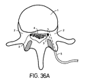
- Figure 36A depicts a lead 5 implanted into the bony aspects of the vertebral body.
- the lumbar spine is shown with the lead inserted into the pedicle 2 of the vertebral body 1 to stimulate nerve roots, particularly as the nerve roots 3 exit the spinal foramen 4.
- the lead 5 is implanted by drilling a hole through the pedicle 2 (from the posterior) and into the vertebral body.
- the lead 5 may then be inserted into the hole and fed to the end. Once in position, the lead 5 may be anchored at the posterior bone entrance site using, for example, a burr cap.
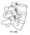
- FIG. 36B shows an isometric drawing of pedicular placement for stimulation of the nerve root as it exits the spinal foramen 4.
- Lead 5 is inserted into the inferior portion of the vertebral pedicle 2 of the vertebral segment to enable stimulation of the dorsal root ganglion 6.
- a lead 5 placed in the superior lateral portion of the vertebral bone will enable stimulation of the spinal nerve 7 of the segment superior.
- lead 5 may be placed so as to target desired neural tissue and avoid other tissue.
- lead 5 is anchored within the vertebral bone, thereby avoiding the risk of lead migration and avoiding compression of nerve tissue common in known techniques.
- lead 5 may be implanted in any other bone areas that are proximal to targeted neural tissue.
- An example of placement to target other neural tissue is illustrated in Figure 36C.
- This Figure illustrates placement for stimulation of the ganglia (8) of the sympathetic trunk.
- the hole for lead 5 is angled more lateral and made deeper up to the wall of the vertebral body 1.
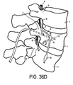
- Figure 36D is an isometric view of the same lead placement shown in Figure 36C.
- the hole in the vertebae begins at the posterior and is extended down the pedicle 2, into the vertebral body 1, toward the ganglion 8, but not through the wall of the vertebral body.
- This method allows stimulation of deep tissues without distrupting soft tissue.
- the lead could be anchored in the posterior bone by a burr hole cap or other means.
- Lead 5 of Figures 36A-D may be adjustable similar to those of Figures 5-9.
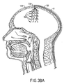
- Figure 38A discloses another embodiment where one or more motor cortex electrodes (MCE) 308 are implanted into the skull of a patient for stimulation and/or recording of the cortex via contact with the dura.
- MCE 308 may be screwed using a burr hole ring 309 and screw 310 within the skull 311 of a patient using known techniques.
- the present embodiment enables several MCEs 308 to be placed to allow flexibility in choosing the best stimulation.
- a MCE targeting grid ( Figure 38C) could be constructed of a material such as, for example, CuSO4, so that the hole locations are visible under magnetic resonance imaging (MRI).
- MCE 308 Placement of the MCE 308 within the skull 311 allows for more accurate placement of the MCEs 308 and avoids the problem of lead migration.
- screw 310 referring to Figure 38B, can be advanced or retracted to ensure an optimal contact between the electrode 308 and dura 314 to maximize stimulation effect while minimizing mechanical deformation of dura and cortex. Further, less invasive surgical procedure is required, thereby minimizing the risk of damage to the dura 314.
- Such a configuration of MCEs 308 may be used for cortex stimulation for any number of disorders, including but not limited to, pain, epilepsy, anxiety/physiological disorders, and movement disorders.
- the present invention also allows the lead to be positioned to be optimally closer to the desired treatment area.
- the embodiments discussed herein illustrate the various techniques that may be used to non-invasively position and re-position therapy delivery elements after they have been surgically implanted. Positioning of the treatment delivery elements may be laterally in any direction or toward or away from the desired treatment site.
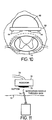
- Figure 10 discloses an embodiment of the present invention where a balloon-like structure 60 is implemented on a dorsal side of a paddle lead 62. The balloon may also be positioned on a lateral side of paddle lead 62.
- Paddle lead 62 may have one or more electrodes 64. Lead 62 may be positioned closer to spinal cord 12 by filling of balloon 60 with a fluid.
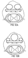
- FIGS 12A-B depict other embodiments wherein a plurality of balloons are implemented to allow more selective adjustment of the electrodes 64 relative to the spinal cord 12. These or other balloons may also be positioned on the sides of the lead so that the lead may be positioned from right to left.
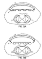
- Figures 13A-B illustrate another embodiment wherein balloon 90 includes a rigid or semi-rigid dorsal component 92.
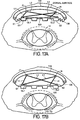
- Figures 14A-B illustrate yet another embodiment wherein balloon 94 includes a rigid or semi-rigid dorsal component 98 having a hinge 96 to allow component to form to the shape of the dorsal aspect of the patient's vertebral canal when balloon 94 is filled with fluid.
- FIG. 12A-B, 13A-B and 14A-B may be controlled by a device similar to the position mechanism of Figure 2. These balloons may be made of an elastic or inelastic material.
- Figure 11 illustrates an alternative technique for adding or removing fluid to balloon 60.
- a septum 70 is provided just underneath the skin 72 of the patient.
- a noncoring needle 74 may be utilized to deliver or remove additional fluid to a reservoir 76 via septum 70. The delivery or removal of fluid may then be controlled to any one of the balloons via tube 78 as needed.
- Figure 15 depicts another embodiment wherein a separate reservoir and septum pair is provided for each of two balloons. In the case of three balloons, three reservoir/septum pairs may be provided.
- FIG 16 discloses yet another embodiment wherein a single septum 80 is provided but reservoirs 82 and 84 may transfer fluid between each other.
- Each reservoir has an associated bulb or depression mechanism 86A-B that can be accessed externally by pressing on the skin 72 of the patient.
- Each depression mechanism includes a spring 87 and ball 88 assembly.
- fluid may be delivered from area 79B of reservoir 84 to reservoir 82 via tube 89.
- bulb 86A is depressed
- fluid in area 79A is delivered from reservoir 82 to reservoir 84.
- a separate reservoir may be utilized to add or remove fluid from reservoirs 82 and 84.
- Such systems are known in the art for an inflatable urinary sphincter and an inflatable penile erector. The system may allow the patient to make these adjustments as needed.
- Figures 17A-E disclose other embodiments whereby the electrodes are adjusted using gliders GL1 and GL2.
- gliders GL1 and GL2 are constrained to move along a groove 115 transverse to ventral component 120 of lead as shown in Figure 17C.
- One or more pulley systems with wires may be utilized to move gliders GL1 and GL2 individually or collectively.
- gliders GL1 and GL2 are attached to ends of rigid arms L1 and L4 respectively.
- the opposite ends of arms L1 and L4 are attached to joints J1 and J4 respectively which are fixed relative to a semi-rigid or flexible dorsal component 110.
- Joints J1 and J4 are also connected to ends of rigid arms L2 and L3 respectively. Opposite ends of arms L2 and L3 are attached to joints S2 and S1 respectively which are fixed relative to ventral component 120 of the lead.
- the entire assembly may be encased within a membrane-like housing 130 to prevent connective tissue in-growth.
- Ventral component 120 may be positioned closer to spinal cord 12 by moving gliders GL1 and GL2 relative to groove 115.
- ventral component 120 may be closest to spinal cord when gliders GL1 and GL2 are positioned under the joints J1 and J4.
- a glider may also be positioned to move parallel to spinal cord 12 along the lead.
- any number of glider geometries may be utilized to adjust to adjust the position of ventral component 120.
- FIGs 18A-C disclose yet other embodiments whereby the electrodes are adjusted using movable, flexing wires.
- ventral component 120 of a lead is positioned relative a semi-rigid dorsal component 125.
- Wires 137 are positioned at opposite sides of the assembly.
- wire 137 is implemented within a sheath 131 whose end is fixed to ventral component 120.
- the distal end of wire 137 is anchored at point P1 and is also fixed relative to ventral component 120 of the lead.
- Wire 137 may be pushed or pulled along sheath 131 causing it to bend or straighten along its body 138.
- wire 137 As wire 137 is pushed toward point P1, it bends causing the body 138 to exert pressure against dorsal component 125 and end P1 to exert pressure against ventral component 120. Wire 137 thus causes a portion of ventral component 120 to move away from dorsal component 125 thereby causing a portion of the lead to expand and position electrodes E1 on that portion to move closer to the spinal cord 12.
- wire 137 When wire 137 is pulled back away from point P1, wire 137 reduces its pressure exerted on dorsal and ventral components 120 and 125, thereby allowing a portion of the lead to reduce its thickness and electrodes E1 on that portion to move away from spinal cord 12.
- a plurality of wire assemblies may be incorporated to adjust the position of lead 120 relative to the spinal cord 12 along various points.
- Figure 19 discloses yet another embodiment whereby the electrodes are adjusted using a piston C1 and a spring S1.
- Piston C1 may be moved to push or pull ventral component 120 relative to semi-rigid dorsal component 125.
- Spring S1 has a preset tension to return ventral component 120 to a default position once the pressure exerted by piston C1 is removed.
- more than one piston/spring assembly may be located laterally as well as along the length of the lead.
- bellows may be used in place of piston C1 and spring S1.
- Figure 20 discloses yet another embodiment whereby the lead is adjusted using a gear mechanism.
- a gear 160 may be rotated about an axis but is held in a fixed position relative to either semi-rigid dorsal component 125 or ventral component 120.
- Slidable elements 165 have ramped surfaces with teeth that interact with gear 160.
- the upper element 165 is coupled to slide relative to semi-rigid dorsal component 125 and the lower slidable element is coupled to slide relative to ventral component 120.
- gear rotates slidable elements 165 are moved in opposite directions relative to each other. With a clockwise turn of gear 160, lower element 165 slides to the left and upper element slides to the right. The elements thereby push ventral component 120 away from semi-rigid dorsal component 125 and toward spinal cord 12.
- Two or more gears may be implemented to minimize asymmetry in lead thickness.
- a gear mechanism may be incorporated into any number of embodiments.
- Figure 21A discloses a toggle mechanism having one gear 170 attached to a component with an associated left or right wing 171. As gear 170 is rotated, wings 171 are rotated accordingly. As shown in Figure 21B, rotation of wings 171 counter-clockwise pushes up against semi-rigid dorsal component 125 causing that portion of lead to increase its thickness, thereby moving that portion of ventral component 120 toward spinal cord 12.
- Gear 170 may be controlled by slidable toothed elements 175. As shown in Figure 21C, there may be two gears (one is shown), each connected to a single-sided wing 171a or 171b to change the lateral lead thickness independently. Wings 171a-b may also have transverse extensions 173a-b (parallel to spinal cord 12) to push against dorsal component 125.
- the lead may be configured in any number of ways using any combination of the above-detailed structures.
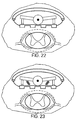
- Figures 22 and 23 illustrate that two or more of the above-detailed techniques (such as wings, flexing wires and/or springs) may be combined to provide the desired control of lead thickness.
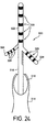
- Figure 24 illustrates yet another embodiment of a lead according to a preferred embodiment of the present invention for use in SCS therapy.
- This design allows movement of electrodes toward or along spinal nerve roots within the spinal canal as they pass caudally and laterally toward their respective foraminae (exits from the vertebral bones).
- a Tuohy needle 314 is utilized and positioned near the spinal cord.
- Lead body 318 is inserted through the lumen 316 of Tuohy needle 314 and positioned near the spinal cord 12.
- a proximal end (not shown) of lead body 318 is ultimately to be connected to a source device (not shown) which may be signal generator 14 of Figure 1, in the case of electrical stimulation, or a drug pump in the case of drug therapy.
- Lead 318 is provided with a distal tip 320 that may be compacted for insertion and unfolded after it has been positioned appropriately within the body.
- Distal tip 320 includes a central portion 322 and at least one span 324 depending therefrom.
- Span 324 is comprised of a flexible, insulative material, such as polyurethane or silicone rubber.
- the term "flexible” as used herein refers to both resilient and non-resilient materials.
- Central portion 322 may have a generally semi-circular cross-section as shown, or may be flat such as in the case of a paddle lead (exemplified in Figure 26).
- Affixed to a surface of spans 324 and to central portion 322 is a series of electrodes 326.
- lead 320 may be configured into a compact insertion position for ease of insertion through lumen 316 of Tuohy needle 314.
- lead tip 320 may be deployed out of Tuohy needle 314, as shown in Figure 24.
- spans 324 are semirigid and tend to span out at a predetermined angle.
- lead 320 may be pulled back into the Tuohy needle 314.
- Needle 314 may be replaced by a sheath component for adjustments after implant.
- spans 324 may be rigid or flaccid and are coupled to a lever 330 capable of adjusting the lateral displacement of spans 324.
- Lever 330 extends from spans 324 to body struts 319. Struts 319 pass inside or along lead body 318 to controllers (not shown). As lever 330 is moved toward distal end of lead 320 by pushing on struts 319, spans 324 are displaced further in a lateral direction. Lever 330 may be coupled to a control mechanism such that spans 324 may be re-positioned at future times to provide optimal treatment therapy.
- Figure 26 discloses another embodiment of a paddle lead 420 having spans 424 which can rotate to lateral positions.
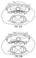
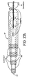
- Figures 27A-B disclose yet another embodiment of a paddle lead 520 capable of extending electrodes laterally to track along spinal nerves.
- Such a mechanism may be similar to that of a car antenna-like device whereby a rigid or semi-rigid wire may extend laterally from lead 520.
- An internal stylet 521 may be utilized to adjust the length of the span 522. As shown in Figure 27A, when stylet 521 is inserted within the lead 520 and is closest to the lead tip, the span 522 is retracted and inside lead 520. As stylet 521 is pulled to the left, span 522 is directed out as shown in Figure 27B to direct electrodes 523 laterally away from lead 520.
- This embodiment may be incorporated with the embodiments of Figures 24-26 and 27A-B to allow adjustment of the extent of the lateral displacement as well as the angle of the lateral displacement.
- the above embodiments illustrate various techniques for allowing therapy delivery elements to be positioned during and/or after implant to effectively provide treatment therapy to the targeted area of the spinal cord or brain. Further, relief may be provided with a lower amplitude, and motor or other undesirable side effects may be minimized. As exemplified in the above embodiments, any number of techniques may be utilized.
- the present invention may also be utilized within the brain to provide electrical stimulation as well as delivery of one or more drugs.
- the present invention may be implemented within a system as disclosed in U.S. Patent Application entitled "Techniques For Selective Activation Of Neurons In The Brain, Spinal Cord Parenchyma, and Peripheral Nerve," invented by Mark Rise and Mike Baudino.
- Treatment therapy may be provided to the brain to treat any number of diseases. Sometimes, the disease will progress to another part of the brain.
- the present invention may thereby be used to advance the electrodes to a different part of the brain. For example, electrodes and/or catheters may be implanted within the brain to treat tremor.
- the present invention may thereby extend or shorten the leads to effect different areas of the brain tissue.
- leads may be adjusted to achieve optimal positioning.
- FIG 37A depicts a lead 37 composed of concentric tubes 38, preferably metal such as platinum. These tubes may be coated with a polymer except for the distal end portions 39 that serve as the electrodes.
- the conductive wires 40 carrying energy to the electrodes are in the interior of the concentric tubes.
- the most distal electrode end 41 may be a small recording microelectrode to help assist in the actual placement of the lead.
- the lead 37 may be implanted within the brain under known techniques.
- a pusher 42 may be placed into the lead through the proximal portion to make the lead 37 stiff during the introduction phase and/or to provide a mechanism to push the concentric tubes 38 out and away from the outer tube or cannula 43. After implant, the outer cannula 43 may optionally be removed.
- the present invention may be operated as an open-loop controlled system.
- the physician or patient may at any time manually or by the use of pumps or motorized elements adjust the positioning of the electrodes in situ and change stimulation parameters. However, this subsequent position adjustment would be independent of any intended changes in stimulation effect or side-effects the patient may be experiencing, and an iterative procedure may be necessary.
- the present invention may incorporate a closed-loop control system which may automatically adjust (1) the positioning of the electrodes in response to a sensed condition of the body such as a response to the treatment therapy; and/or (2) the electrical stimulation parameters in response to a sensed symptom or an important related symptom indicative of the extent of the disorder being treated.
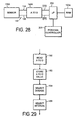
- a sensor 130A ( Figure 28) that senses a condition of the body is preferably utilized.
- sensor 130A may detect patient position to discern whether the patient is lying down or is in an erect position.
- spinal cord stimulation becomes strong when the patient lies down due to the spinal cord moving in a dorsal direction toward the lead.
- the position control mechanism may adjust electrodes to move away from spinal cord.
- one or more recording electrodes may be utilized to provide feedback.
- sensor 130A More detailed description of sensor 130A, other examples of sensors and the feedback control techniques are disclosed in U.S. Patent No. 5,716,377 entitled “Method of Treating Movement Disorders By Brain Infusion,” issued on February 10, 1998 and assigned to Medtronic, Inc.
- the output of sensor 130A is coupled by a cable 132 comprising conductors 134 and 135 to the input of analog to digital converter 140A.
- the output of the sensor 130A could communicate through a "body bus" communication system as described in U.S. Patent No. 5,113,859 (Funke), assigned to Medtronic.
- the output of an external feedback sensor 130A would communicate with signal generator 14 through a telemetry down-link.
- the output of the analog to digital converter 140A is connected to a microprocessor 200 via terminals EF2 BAR and EF3 BAR.
- the sensor signals may then be stored in a memory device such as a Random Access Memory (RAM) 102a.
- RAM Random Access Memory
- Such a configuration may be one similar to that shown in U.S. Patent No. 4,692,147 ("'147 Patent") except that before converter 140A is connected to the terminals, the demodulator of the '147 patent (identified by 101) would be disconnected.
- Microprocessor 200 may then be coupled to a
- microprocessor 200 and analog to digital converter 140A would not be necessary.
- the output from sensor 130A can be filtered by an appropriate electronic filter in order to provide a control signal for position controller.
- An example of such a filter is found in U.S. Patent No. 5,259,387 "Muscle Artifact Filter", Issued to Victor de Pinto on November 9, 1993.
- Closed-loop control of position controller can be achieved by a modified form of the ITREL II signal generator.
- the output of the analog to digital converter 140A is connected to microprocessor 200 through a peripheral bus 202 including address, data and control lines.
- Microprocessor 200 processes the sensor data in different ways depending on the type of transducer in use. Microprocessor may adjust the position of the electrodes in response to the sensor signal information provided by sensor 130A. The type of control provided depends upon the type of position controller utilized and the mechanism utilized (discussed above) to position the electrodes. In the case where position controller relies on electrical energy to cause mechanical movement (e.g., pumps, motors and the like) or is purely electrical control, microprocessor 200 or a second microprocessor may serve as the position controller.
- position controller In the case where position requires mechanical control, an appropriate controlling device is used.
- position controller may be incorporated within a reservoir system for holding the fluid outside the lead's balloon. Torque from percutaneous instruments that engages in a mechanical component may also be used.
- the present invention may also incorporate a closed-loop feedback system to provide automatic adjustment of the electrical stimulation therapy.
- a closed-loop feedback system to provide automatic adjustment of the electrical stimulation therapy.
- Such is system is disclosed in U.S. Patent No. 5,792,186 entitled “Method and Apparatus of Treating Neurodegenerative Disorders by Electrical Brain Stimulation," and assigned to Medtronic, Inc.
- the system may incorporate the same sensor 130A discussed above or one or more additional sensors 130 to provide feedback to provide enhanced results.
- Sensor 130 can be used with a closed loop feedback system in order to automatically determine the level of electrical stimulation necessary to provide the desired treatment.
- sensor 130 may be a motion detector implanted in the arm. More detailed description of sensor 130, other examples of sensors and the feedback control techniques are disclosed in U.S. Patent No.
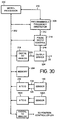
- Closed-loop electrical stimulation can be achieved by a modified form of the ITREL II® signal generator which is described in Figure 30.
- the output of the analog to digital converter 206 is connected to a microprocessor 200 through a peripheral bus 202 including address, data and control lines.
- Microprocessor 200 processes the sensor data in different ways depending on the type of transducer in use. When the signal on sensor 130 exceeds a level programmed by the clinician and stored in a memory 204, increasing amounts of stimulation will be applied through an output driver 224. For some types of sensors, a microprocessor and analog to digital converter will not be necessary.
- the output from sensor 130 can be filtered by an appropriate electronic filter in order to provide a control signal for signal generator 14. An example of such a filter is found in U.S. Patent No. 5,259,387 "Muscle Artifact Filter", Issued to Victor de Pinto on November 9, 1993.
- the stimulus pulse frequency is controlled by programming a value to a programmable frequency generator 208 using bus 202.
- the programmable frequency generator 208 provides an interrupt signal to microprocessor 200 through an interrupt line 210 when each stimulus pulse is to be generated.
- the frequency generator 208 may be implemented by model CDP1878 sold by Harris Corporation.
- the amplitude for each stimulus pulse is programmed to a digital to analog converter 218 using bus 202.
- the analog output is conveyed through a conductor 220 to an output driver circuit 224 to control stimulus amplitude.
- Microprocessor 200 also programs a pulse width control module 214 using bus 202.
- the pulse width control 214 provides an enabling pulse of duration equal to the pulse width via a conductor . Pulses with the selected characteristics are then delivered from signal generator 14 to the lead to the target locations of spinal cord 12.
- Microprocessor 200 executes an algorithm shown in Figures 31-5 to provide stimulation with closed loop feedback control.
- the clinician programs certain key parameters into the memory of the implanted device via telemetry. These parameters may be updated subsequently as needed.
- Step 400 in Figure 31 indicates the process of first choosing whether the neural activity at the stimulation site is to be blocked or facilitated (step 400(1)) and whether the sensor location is one for which an increase in the neural activity at that location is equivalent to an increase in neural activity at the stimulation target or vice versa (step 400(2)).
- the clinician must program the range of values for pulse width (step 400(3)), amplitude (step 400(4)) and frequency (step 400(5)) which signal generator 14 may use to optimize the therapy.
- the clinician may also choose the order in which the parameter changes are made (step 400(6)). Alternatively, the clinician may elect to use default values.
- the algorithm for selecting parameters is different depending on whether the clinician has chosen to block the neural activity at the stimulation target or facilitate the neural activity.
- Figures 31-35 detail the steps of the algorithm to make parameter changes.
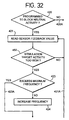
- the algorithm uses the clinician programmed indication of whether the neurons at the particular location of the stimulating electrode are to be facilitated or blocked in order to decide which path of the parameter selection algorithm to follow (step 420, Figure 32). If the neuronal activity is to be blocked, signal generator 14 first reads the feedback sensor 130 in step 421. If the sensor values indicate the activity in the neurons is too high (step 450), the algorithm in this embodiment first increases the frequency of stimulation in step 424 provided this increase does not exceed the preset maximum value set by the physician. Step 423 checks for this condition. If the frequency parameter is not at the maximum, the algorithm returns to step 421 through path 421A to monitor the feedback signal from sensor 130.
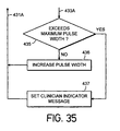
- the algorithm next increases the pulse width in step 426 ( Figure 33), again with the restriction that this parameter has not exceeded the maximum value as checked for in step 451 through path 423A. Not having reached maximum pulse width, the algorithm returns to step 421 to monitor the feedback signal from sensor 130. Should the maximum pulse width have been reached, the algorithm next increases amplitude in a like manner as shown in steps 427 and 428. In the event that all parameters reach the maximum, a notification message is set in step 429 to be sent by telemetry to the clinician indicating that therapy delivery device 14 is unable to reduce neural activity to the desired level.
- the algorithm would follow a different sequence of events.
- the frequency parameter would be fixed at a value chosen by the clinician to facilitate neuronal activity in step 430 ( Figure 34) through path 420A ( Figure 32).
- the algorithm uses the values of the feedback sensor to determine if neuronal activity is being adequately controlled. In this case, inadequate control indicates that the neuronal activity of the stimulation target is too low.
- Neuronal activity is increased by first increasing stimulation amplitude (step 434) provided it doesn't exceed the programmed maximum value checked for in step 433.
- the algorithm increases pulse width to its maximum value in steps 435 and 436 ( Figure 35).
- the algorithm returns to step 431 through path 431A, and the feedback sensor again is read.
- steps 410 through 415 constitute the method to do this.
- a timer is reset in step 415. If there is no need to change any stimulus parameters before the timer has counted out, then it may be possible due to changes in neuronal activity to reduce the parameter values and still maintain appropriate levels of neuronal activity in the target neurons.
- signal generator 14 tries reducing a parameter in step 413 to determine if control is maintained. If it is, the various parameter values will be ratcheted down until such time as the sensor values again indicate a need to increase them. While the algorithms in Figures 31-35 follow the order of parameter selection indicated, other sequences may be programmed by the clinician.
- the stimulation might be applied periodically during the period of stimulation/infusion either routinely or in response to sensor or patient generated demand.
- stimulation could be applied continuously with infusion occurring periodically.
- Patient activation of either infusion or stimulation may occur as a result of an increase in symptoms being experienced by the patient.
- the infusion of an agent to activate a neuronal population might be alternated with application of electrical stimulation of that same population.
- the present invention may be used to selectively position stimulation electrodes optimally closer to the targeted neural tissue to more effectively deliver a desired treatment therapy.
- the present invention may also be implemented within a drug delivery system and/or may be implemented to provide treatment therapy to other parts of the body such as the brain, nerves, muscle tissue, or neural ganglia. Further, the various embodiments of the present invention may be implemented within a percutaneous lead or a paddle lead.
Abstract
Description
- The present invention relates to stimulation or drug delivery systems, and more particularly relates to systems for positioning the treatment therapy elements, such as electrodes or catheters, to provide more effective treatment therapy.
- Electrical stimulation techniques have become increasingly popular for treatment of pain and various neurological disorders. Typically, an electrical lead having one or more electrodes is implanted near a specific site in the brain or spinal cord of a patient. The lead is coupled to a signal generator which delivers electrical energy through the electrodes to nearby neurons and neural tissue. The electrical energy delivered through the electrodes creates an electrical field causing excitation of the nearby neurons to directly or indirectly treat the pain or neurological disorder.
- Presently, only highly skilled and experienced practitioners are able to position a stimulation lead in such a way that the desired overlap between stimulation sites and target tissue is reached and desired results are obtained over time with minimal side effects. It requires much time and effort to focus the stimulation on the desired body region during surgery. These leads cannot be moved by the physician without requiring a second surgery.
- The major practical problem with these systems is that even if the paresthesia (sensation of stimulation) location covers the pain area perfectly during surgery, the required paresthesia pattern often changes later due to lead migration, histological changes (such as the growth of connective tissue around the stimulation electrode), neural plasticity or disease progression. As a result, the electrical energy may stimulate undesired portions of the brain or spinal cord.
- Maintaining the lead in a fixed position and in proximity to the treatment site is therefore highly desirable. Presently known systems are susceptible to lead migration. Accordingly, the lead may migrate such that the targeted tissue is outside of the effective steerable treatment range of the lead. Additionally, for some treatment applications, the lead just cannot be placed optimally to provide the desired treatment therapy. For example, in the case of treatment of lower back pain, electrical stimulation may be provided at the middle thoracic vertebral segments, T6-T9. With currently available systems, this often fails mostly due to the great thickness of the cerebral spinal fluid (CSF) layer.
- Alternatively, it is desirable to redirect paresthesia without requiring a second surgery to account for lead migration, histological changes, neural plasticity or disease progression. With present single channel approaches, however, it is difficult to redirect paresthesia afterwards, even though limited readjustments can be made by selecting a different contact combination, pulse rate, pulse width or voltage. These problems are found not only with spinal cord stimulation (SCS), but also with peripheral nerve stimulation (PNS), depth brain stimulation (DBS), cortical stimulation and also muscle or cardiac stimulation. Similar problems and limitations are present in drug infusion systems.
- Recent advances in this technology have allowed the treating physician or the patient to steer the electrical energy delivered by the electrodes once they have been implanted within the patient. For example, U.S. Patent No. 5,713,922 entitled "Techniques for Adjusting the Locus of Excitation of Neural Tissue in the Spinal Cord or Brain," issued on February 3, 1998 to and assigned to Medtronic, Inc. discloses one such example of a steerable electrical energy. Other techniques are disclosed in Application Serial Nos. 08/814,432 (filed March 10, 1997) and 09/024,162 (filed February 17, 1998). Changing the electric field distribution changes the distribution of neurons recruited during a stimulus output, and thus provides the treating physician or the patient the opportunity to alter the physiological response to the stimulation. The steerability of the electric field allows the user to selectively activate different groups of nerve cells without physically moving the lead or electrodes.
- These systems, however, are limiting in that the steerable electric field is limited by the location of the electrodes. If the electrodes move outside of the desired treatment area or if the desired stimulation area is different due to histological changes or disease migration, the desired treatment area may not be reached even by these steerable electrodes. Further, even if these steerable electrodes may be able to stimulate the desired neural tissue, the distance from the electrodes to the tissue may be too large such that it would require greater electrical power to provide the desired therapy. It has been shown that only a fraction of the current from modern stimulation devices gets to the neurons of interest. See W.A. Wesselink et al. "Analysis of Current Density and Related Parameters in Spinal Cord Stimulation," IEEE Transactions on Rehabilitation Engineering, Vol. 6, pp. 200-207 (1998). This not only more rapidly depletes the energy reserve, but it also may stimulate undesired neural tissue areas thereby creating undesired side effects such as pain, motor affects or discomfort to the patient.
- In short, there remains a need in the art to provide an electrical stimulation device that is not susceptible to lead migration and that may be positioned in proximity to the treatment site. In addition, there remains a need in the art to provide an electrical stimulation device that may be adjusted to account for lead migration, patient movement or position, histological changes, and disease migration.
- As explained in more detail below, the present invention overcomes the above-noted and other shortcomings of known electrical stimulation and drug delivery techniques. The present invention, according to one aspect, provides a system for providing treatment therapy to targeted tissue comprising in combination:
- (a) a therapy delivery device;
- (b) at least one therapy delivery element coupled to the therapy delivery device for providing treatment therapy to the targeted tissue; and
- (c) at least one position control mechanism coupled to at least one of the therapy delivery elements for adjusting, at any time after implanting the therapy delivery elements, the position of the therapy delivery element relative to the targeted tissue.
-
- The position may be adjusted laterally in any number of directions relative to the lead or toward or away from the excitable tissue of interest. Any number of position control mechanisms may be incorporated to selectively adjust the position of the therapy delivery elements. Also, a position controller such as a microprocessor may be utilized to operate the position control mechanism to position the therapy delivery elements.
- According to another aspect, there is provided an implantable lead for providing therapy to a body comprising:
- (a) an elongate central portion;
- (b) at least one extendable member having an end, the extendable member depending from the central portion and being adapted to assume a compact position, in which the end is disposed in close proximity to the central portion, and an extended position, in which the extendable member is disposed removed from the central portion; and
- (c) at least one therapy delivery element disposed on the extendable member for delivering therapy to the body.
-
- According to another aspect, there is provided a system for providing neurostimulation therapy to targeted tissue comprising in combination:
- (a) a signal generator;
- (b) at least one housing member implantable within a bone near the targeted tissue and adjustable relative to the bone; and
- (c) at least one electrode coupled to said signal generator and attached to a distal end of the housing member for providing electrical stimulation to the targeted tissue.
-
- According to another aspect, there is provided an implantable paddle-like lead for providing treatment therapy to targeted tissue of a body comprising:
- (a) a middle portion having at least one central therapy delivery element on a ventral side;
- (b) at least two end portions, each end portion having at least one end therapy delivery element on the ventral side; and
- (c) means capable of expanding the middle portion such that the central therapy delivery element is positioned away from a dorsal side of the lead.
-
- According to another aspect, there is provided an implantable paddle-like lead for providing treatment therapy to targeted tissue of a body comprising:
- (a) a ventral side having at least one therapy delivery element;
- (b) a dorsal side opposite the ventral side;
- (c) at least one balloon-like member attached to
the back side of the lead, the balloon-like member
capable of expanding by receiving a fluid,
whereby expansion of the balloon-like member resulting in positioning at least one of the therapy delivery elements closer to or further from the targeted tissue. -
- According to another aspect, there is provided an implantable paddle-like lead for providing treatment therapy to targeted tissue of a body comprising:
- (a) a ventral side having at least one therapy delivery element;
- (b) at least one means attached to the ventral side of the lead capable of movement; and
- (c) a membrane covering the means capable of
movement,
whereby movement of the means capable of movement results in lead expansion and positioning of at least one of the therapy delivery elements closer to or further from the targeted tissue. -
- According to another aspect, there is provided an implantable paddle-like lead for providing treatment therapy to targeted tissue of a body comprising:
- (a) a ventral side having at least one therapy delivery elements;
- (b) at least one gear mechanism attached to the lead capable of rotating; and
- (e) at least one arm coupled to the gear;
whereby rotation of at least one arm results in lead expansion and positioning of at least one of the therapy delivery elements closer to or further from the targeted tissue. -
- In other embodiments of the present invention, one or more therapy delivery elements may be placed within the cranial or vertebral bone of the patient so as to maintain the therapy delivery elements in a fixed position relative to the targeted neural tissue. The therapy delivery elements may thereafter be adjusted with a position control mechanism and/or a position controller to improve the desired treatment therapy.
- By using the foregoing techniques, therapy delivery elements may be positioned to provide treatment therapy such as electrical stimulation and/or drug infusion to a precise target. Additionally, the present invention accounts for the problems associated with lead migration, histological changes, neural plasticity or disease progression.
- Optionally, the present invention may incorporate a closed-loop system which may automatically adjust (1) the positioning of the therapy delivery elements in response to a sensed condition of the body such as a response to the treatment therapy; and/or (2) the treatment therapy parameters in response to a sensed symptom or an important related symptom indicative of the extent of the disorder being treated.
- Examples of the more important features of this invention have been broadly outlined above so that the detailed description that follows may be better understood and so that contributions which this invention provides to the art may be better appreciated.
- These and other advantages and features of the invention will become apparent upon reading the following detailed description, which is given by way of example only, and referring to the accompanying drawings in which like numbers refer to like parts throughout and in which:
- Figure 1 depicts a neurostimulation device in accordance with an embodiment of the present invention;
- Figure 2 is a cross-sectional view of spinal cord at spinal bone level T-6 having an implanted lead in accordance with a preferred embodiment of the present invention;
- Figure 3 illustrates a position controller having metal bellows;
- Figure 4 illustrates a position controller having a piston;
- Figures 5A-D disclose embodiments of the present invention where electrodes are anchored within vertebral bones of the spinal cord;
- Figure 6 discloses another embodiment of the present invention having a collar screwed into vertebral bone;
- Figure 7 discloses another embodiment of the present invention having a collar with an "O" ring to hold an electrode housing in position by pressure;
- Figures 8 and 9 disclose other embodiments of the present invention where a plurality of electrodes are anchored through vertebral bones of the spinal cord;
- Figure 10 discloses another embodiment of the present invention where a balloon is implemented on a dorsal side of a paddle lead;
- Figure 11 illustrates an alternative technique for adding or removing fluid to a balloon;
- Figures 12A-B depict other embodiments wherein a plurality of balloons are implemented to allow more selective adjustment of the electrodes relative to the spinal cord;
- Figures 13A-B illustrate another embodiment wherein the balloon includes a rigid or semi-rigid dorsal component;
- Figures 14A-B illustrate yet another embodiment wherein the balloon includes a rigid or semi-rigid dorsal component having a hinge;
- Figure 15 depicts another embodiment of a reservoir system for adjusting fluid amounts in a lead;
- Figure 16 depicts yet another embodiment of a reservoir system for adjusting fluid amounts in a lead;
- Figures 17A-E disclose other embodiments whereby a portion of the lead body thickness is adjusted using gliders;
- Figures 18A-C disclose yet other embodiments whereby a portion of the lead body thickness is adjusted using movable wires;
- Figure 19 discloses yet another embodiment whereby a portion of the lead body thickness is adjusted using a piston and a spring;
- Figure 20 discloses yet another embodiment whereby a portion of the lead body thickness is adjusted using a gear mechanism;
- Figures 21A-C disclose various embodiments of the present invention utilizing a single or dual gear mechanism;
- Figures 22 and 23 illustrate embodiments of the present invention where more than one of the elements of the above figures are implemented;
- Figure 24 illustrates yet another embodiment of a lead having two spans extending laterally from its body;
- Figure 25 illustrates yet another embodiment of a lead having two spans that are adjustable by use of guide struts;
- Figure 26 discloses an embodiment of a paddle lead having movable lateral spans;
- Figures 27A-B disclose yet another embodiment of a paddle lead capable of extending electrodes laterally;
- Figure 28 is a schematic block diagram of a sensor and an analog to digital converter circuit used in a preferred embodiment of the invention;
- Figure 29 is a flow chart illustrating a preferred form of a microprocessor program for utilizing the sensor to control the treatment therapy provided to the neural tissue;
- Figure 30 is a schematic block diagram of a microprocessor and related circuitry used in a preferred embodiment of the invention;
- Figures 31-35 are flow charts illustrating a preferred form of a microprocessor program for generating stimulation pulses to be administered to neural tissue;
- Figures 36A-D illustrate other embodiments of a lead being implanted within a vertebral bone of a patient;
- Figures 37A-B illustrate an embodiment of an extendable lead for implant within a brain; and
- Figures 38A-C illustrate an embodiment of the present invention wherein a plurality of MCEs are implanted within the skull of a patient.
-
- Figure 1 depicts a neurostimulation therapy delivery device 14 in accordance with an embodiment of the present invention. Therapy delivery device 14 made in accordance with the preferred embodiment is preferably implanted below the skin of a patient or, alternatively, may be an external device. Therapy delivery device 14 may be implanted as shown in Figure 1, in the abdomen or any other portion of the
body 10. One or more leads 23 are positioned to stimulate a specific site in aspinal cord 12. Therapy delivery device 14 may take the form of a modified signal generator Model 7424 manufactured by Medtronic, Inc. under the trademark Itrel II®.Lead 23 may take the form of any of the leads sold with the Model 7424, for stimulating a spinal cord, and is coupled to therapy delivery device 14 by one or moreconventional conductors 16 and 18.Lead 23 may include a paddle lead, a lead having one or more therapy delivery devices such as stimulation electrodes and/or catheters, or a combination catheter/lead capable of providing electrical stimulation and drug delivery.Lead 23 may also have recording electrodes. Exemplary embodiments oflead 23 incorporating the principles of the present invention are shown in the figures of the present application and discussed herein. - As shown in Figure 1, the distal end of
lead 23 terminates in one or more therapy delivery elements such as stimulation electrodes generally implanted into or near a selected portion of the spinal cord by conventional surgical techniques. The location of the electrodes is determined by the type of treatment that is desired. Any number of electrodes may be used for various applications. Each of the electrodes are preferably individually connected to therapy delivery device 14 throughlead 23 andconductors 16 and 18.Lead 23 is surgically implanted either by a laminotomy or by a percutaneous needle. - Therapy delivery device or signal generator 14 may be programmed to provide a predetermined stimulation dosage in terms of pulse amplitude, pulse width, pulse frequency, or duty cycle. As preferred, a
programmer 20 may be utilized to provide stimulation parameters to therapy delivery device 14 via telemetry. Programmer is coupled to anantenna 24 viaconductor 22. - The system may optionally include one or more sensors to provide closed-loop feedback control of the treatment therapy and/or electrode positioning. One or more sensors are attached to or implanted into a portion of a patient's body suitable for detecting a physical and/or chemical symptom or an important related symptom of the body. The feedback aspect of the present invention is discussed in further detail herein.
- Although the invention will be described herein with reference to spinal cord stimulation (SCS) procedures, Cortical Surface Stimulation, and or Deep Brain Stimulation (DBS) it will be recognized that the invention finds utility in applications other than SCS procedures, including other applications such as Peripheral Nerve or Ganglia Stimulation, Intra-Spinal Stimulation, Sacral Root Stimulation, or Intraventricular Cerebral Stimulation. In addition, the invention finds applicability to SCS procedures where the lead is placed in the intrathecal or subdural space. The present invention may also be utilized to provide stimulation of various muscles of the body such as the cardiac muscle. The invention also finds utility to drug therapy where electrical components are replaced with conduits and catheters for conducting drug material to the therapy site. In this case, especially, the lead may be placed in the intrathecal or subdural space.
- Figure 2 is a cross-sectional view of
spinal cord 12 at spinal bone level T-6 having an implanted lead 23A in accordance with a preferred embodiment of the present invention.Spinal cord 12 generally includeswhite matter 31,grey matter 33, and a surroundingdural sack 30. As shown, lead 23A is implanted in the epidural space outside ofdural sack 30, but may alternatively be implanted in intrathecal spinal space or subcortically beneathdura 30. Lead 23A has a curved shape to match the shape ofdura 30. The curvature may be matched to each spinal level or may be a general shape to approximately match all levels of spinal cord. Alternatively, lead 23A may be flat such that it "grips" the vertebral bone on its dorsal edges and is less prone to migration or rotation. Lead 23A has adorsal side 125 away fromspinal cord 12 and aventral side 120 facingspinal cord 12. - Figures 2-4 show the average width, height and spacing of tissue components at vertebral bone level T6. The dashed lines in these figures indicate distances of one standard deviation from the mean. See J. Holsheimer et al., "MR Assessment of the Normal Position of the Spinal Cord in the Spinal Cannal," Am. J. Neuroradiology, Vol. 15, pp. 951-959 (1994).
- Referring still to Figure 2, lead 23A has two
lateral electrode contacts central electrode contact 33 in the central portion of lead 23A. Lateral and central electrodes 31-33 may be anodes, cathodes or nonactive. Alternatively, any one or more of lateral and central electrodes 31-33 may be recording electrodes or drug delivery ports. Lead 23A is preferably able to control the dorsal cerebral spinal fluid (CSF) width, even though it is placed outside of dura. In accordance with the present invention, lead 23A includes a position control mechanism capable of adjusting the position of one or more of the lateral or central electrodes 31-33. As shown,central electrode 33 is at a maximal distance dorsally fromspinal cord 12. A position control mechanism may adjust the distance betweencentral electrode 33 and thespinal cord 12. In the embodiment of Figure 2, the position control mechanism is in the form of acavity 34 within lead 23A which is able to expand and fill with fluid (controlled by a pump (not shown)) or other matter in the epidural space to reduce the separation betweencentral electrode 33 andspinal cord 12. A pump (not shown) may be powered by signal generator 14 that also provides the stimulation energy for the electrodes at lateral and central electrodes 31-33 and a signal for controlling the position control mechanism. Alternatively, position control mechanism may be adjusted using external means and power such as a magnetic signal, a percutaneous needle or bulb on another component that can be pushed. Advantageously,central electrode 33 may be positioned such that the targeted neural tissue is stimulated with optimal efficacy and minimal side effects. - As shown in Figures 3 and 4, the position control mechanism may take any number of embodiments for allowing movement of the electrodes and holding the electrodes in position. Figure 3 illustrates a position control mechanism having metal bellows 35 and Figure 4 illustrates a position control mechanism having a
piston 36. The bellows 35 of Figure 3 may alternatively be a threaded rod. A spring may be added to return the electrode to a less extended position. - Further, the position control mechanism may control all or a selective group of electrodes. For example, one position control mechanism may control a longitudinal or transverse row of electrodes. Alternatively, each electrode to be adjusted may have its own individual position control mechanism.
- The position control mechanism of the above embodiments is preferably controlled by a position controller which is discussed in further detail herein. The position control mechanism is preferably adjustable such that it does not unduly depress neural tissue or hinder blood flow. Sensing feedback may be utilized, for example by a mechanical measure within a lead or an ultrasound or other sensor to give information about the distance. Sensing feedback may also be utilized to automatically adjust the positioning of the electrodes to provide optimum treatment therapy. Sensing feedback is discussed in further detail herein.
- Figures 5-9 disclose another group of embodiments of the present invention where electrodes are anchored to vertebral bones of the spinal cord. Alternatively, the electrodes may be implanted in the cortical bone of the skull. Electrodes may be positioned by drilling one or more holes at preselected locations in the bone. Leads having one or more electrodes may then be passed through the holes and positioned inside the vertebral canal/skull at optimal locations or distances from the target neural tissue. Electrodes may then be selectively adjusted in position after the implant. The depth of the electrodes may then be adjusted to provide the optimal stimulation therapy.
- As shown in Figure 5A, an
electrode 40 at the end of a threadedhousing 43 is provided by drillinghousing 43 intobone 42 surroundingspinal cord 12. For dorsal column stimulation,bone 42 is preferably the dorsal aspect of vertebral bone. The lead 23B is coupled toelectrode 40 and extends out through atop portion 41 of threadedhousing 43. Figures 5B-D illustrate exemplary embodiments of the top portion ofhousing 41 to allow for engagement of various turning devices. Figure 5B depicts acavity 45 to provide engagement of a screwdriver-like device to turnhousing 43 to adjust position ofelectrode 40 relative tospinal cord 12. Figure 5C depicts a similar device but providing engagement of a slotted screwdriver-like device. Figure 5D depicts ahexagonal cavity 47 for engagement of a hexagonal wrench-like device or percutaneous needle.Housing 43 preferably is threaded with a high pitch so that a relatively small turn provides relatively larger positioning ofelectrode 40 relative to thespinal cord 12. This minimizes the problem oflead 23B wrapping aroundhousing 43. - Figure 6 discloses another embodiment of the present invention having a
collar 50 screwed intobone 42. Aninner housing 52 similar to thehousing 43 of Figure 5 may be used to moveelectrode 40 relative tocollar 50. This embodiment allows adjustment ofelectrode 40 at times after the system has been implanted and is less affected by growth of tissue overhousing 52 andcollar 51 to limit subsequent turning ofhousing 52 relative tocollar 51. Figure 7 discloses another embodiment wherecollar 51 has an "O"ring 54 to holdhousing 53 in position by pressure. Other means to lockhousing 53 in position are also possible. - As shown in Figures 8 and 9, a plurality of electrodes may be provided that can be selectively or collectively adjusted relative to
spinal cord 12. These electrodes may also be provided in a three-dimensional configuration alongspinal cord 12. Further, though electrodes may be positioned closer tospinal cord 12, they preferably do not break thedural sack 30 to avoid leakage of CSF. Figure 9 shows a ball andsocket 905 or other swivel mechanism to allow turning of the housing but not the lead. Advantageously, placement of the lead through the vertebral bone avoids the problem of lead migration. - Alternatively, the lead may be implanted into the bone, as opposed to implant all the way through the bone, as illustrated in Figures 36A-D. For example, Figure 36A depicts a
lead 5 implanted into the bony aspects of the vertebral body. The lumbar spine is shown with the lead inserted into thepedicle 2 of thevertebral body 1 to stimulate nerve roots, particularly as thenerve roots 3 exit thespinal foramen 4. Thelead 5 is implanted by drilling a hole through the pedicle 2 (from the posterior) and into the vertebral body. Thelead 5 may then be inserted into the hole and fed to the end. Once in position, thelead 5 may be anchored at the posterior bone entrance site using, for example, a burr cap. By keeping the lead hole medial and centered, the nerve roots can be stimulated. The specific target nerve site may be selected by varying the placement of thelead 5 relative to the vertebral bone. Figure 36B shows an isometric drawing of pedicular placement for stimulation of the nerve root as it exits thespinal foramen 4.Lead 5 is inserted into the inferior portion of thevertebral pedicle 2 of the vertebral segment to enable stimulation of thedorsal root ganglion 6. By way of another example, in Figure 36C, alead 5 placed in the superior lateral portion of the vertebral bone will enable stimulation of thespinal nerve 7 of the segment superior. Advantageously, lead 5 may be placed so as to target desired neural tissue and avoid other tissue. In addition,lead 5 is anchored within the vertebral bone, thereby avoiding the risk of lead migration and avoiding compression of nerve tissue common in known techniques. - In addition,
lead 5 may be implanted in any other bone areas that are proximal to targeted neural tissue. An example of placement to target other neural tissue is illustrated in Figure 36C. This Figure illustrates placement for stimulation of the ganglia (8) of the sympathetic trunk. The hole forlead 5 is angled more lateral and made deeper up to the wall of thevertebral body 1. Figure 36D is an isometric view of the same lead placement shown in Figure 36C. The hole in the vertebae begins at the posterior and is extended down thepedicle 2, into thevertebral body 1, toward theganglion 8, but not through the wall of the vertebral body. This method allows stimulation of deep tissues without distrupting soft tissue. Again the lead could be anchored in the posterior bone by a burr hole cap or other means.Lead 5 of Figures 36A-D may be adjustable similar to those of Figures 5-9. - The advantages of fixing a lead to a vertebral bone may also be implemented in Cortical Brain Stimulation applications. Figure 38A discloses another embodiment where one or more motor cortex electrodes (MCE) 308 are implanted into the skull of a patient for stimulation and/or recording of the cortex via contact with the dura. As shown in Figure 38B,
MCE 308 may be screwed using aburr hole ring 309 and screw 310 within theskull 311 of a patient using known techniques. Advantageously, the present embodiment enablesseveral MCEs 308 to be placed to allow flexibility in choosing the best stimulation. A MCE targeting grid (Figure 38C) could be constructed of a material such as, for example, CuSO4, so that the hole locations are visible under magnetic resonance imaging (MRI). Placement of theMCE 308 within theskull 311 allows for more accurate placement of theMCEs 308 and avoids the problem of lead migration. In addition,screw 310, referring to Figure 38B, can be advanced or retracted to ensure an optimal contact between theelectrode 308 anddura 314 to maximize stimulation effect while minimizing mechanical deformation of dura and cortex. Further, less invasive surgical procedure is required, thereby minimizing the risk of damage to thedura 314. Such a configuration ofMCEs 308 may be used for cortex stimulation for any number of disorders, including but not limited to, pain, epilepsy, anxiety/physiological disorders, and movement disorders. - In addition to minimizing lead migration, the present invention also allows the lead to be positioned to be optimally closer to the desired treatment area. The embodiments discussed herein illustrate the various techniques that may be used to non-invasively position and re-position therapy delivery elements after they have been surgically implanted. Positioning of the treatment delivery elements may be laterally in any direction or toward or away from the desired treatment site. Figure 10 discloses an embodiment of the present invention where a balloon-
like structure 60 is implemented on a dorsal side of apaddle lead 62. The balloon may also be positioned on a lateral side ofpaddle lead 62.Paddle lead 62 may have one ormore electrodes 64.Lead 62 may be positioned closer tospinal cord 12 by filling ofballoon 60 with a fluid. In the event that it is desired that lead 62 be moved away fromspinal cord 12, fluid may be removed from 60. Figures 12A-B depict other embodiments wherein a plurality of balloons are implemented to allow more selective adjustment of theelectrodes 64 relative to thespinal cord 12. These or other balloons may also be positioned on the sides of the lead so that the lead may be positioned from right to left. Figures 13A-B illustrate another embodiment whereinballoon 90 includes a rigid or semi-rigiddorsal component 92. Figures 14A-B illustrate yet another embodiment whereinballoon 94 includes a rigid or semi-rigiddorsal component 98 having ahinge 96 to allow component to form to the shape of the dorsal aspect of the patient's vertebral canal whenballoon 94 is filled with fluid. - The amount of fluid in the balloon of Figures 12A-B, 13A-B and 14A-B may be controlled by a device similar to the position mechanism of Figure 2. These balloons may be made of an elastic or inelastic material. Figure 11 illustrates an alternative technique for adding or removing fluid to balloon 60. A
septum 70 is provided just underneath theskin 72 of the patient. Anoncoring needle 74 may be utilized to deliver or remove additional fluid to areservoir 76 viaseptum 70. The delivery or removal of fluid may then be controlled to any one of the balloons viatube 78 as needed. Figure 15 depicts another embodiment wherein a separate reservoir and septum pair is provided for each of two balloons. In the case of three balloons, three reservoir/septum pairs may be provided. Figure 16 discloses yet another embodiment wherein asingle septum 80 is provided butreservoirs depression mechanism 86A-B that can be accessed externally by pressing on theskin 72 of the patient. Each depression mechanism includes aspring 87 andball 88 assembly. For example, by depressingmechanism 86B, fluid may be delivered fromarea 79B ofreservoir 84 toreservoir 82 viatube 89. Also, whenbulb 86A is depressed, fluid inarea 79A is delivered fromreservoir 82 toreservoir 84. Also, a separate reservoir may be utilized to add or remove fluid fromreservoirs - Figures 17A-E disclose other embodiments whereby the electrodes are adjusted using gliders GL1 and GL2. As shown in Figures 17A-B, gliders GL1 and GL2 are constrained to move along a
groove 115 transverse toventral component 120 of lead as shown in Figure 17C. One or more pulley systems with wires may be utilized to move gliders GL1 and GL2 individually or collectively. Referring back to Figures 17A-B, gliders GL1 and GL2 are attached to ends of rigid arms L1 and L4 respectively. The opposite ends of arms L1 and L4 are attached to joints J1 and J4 respectively which are fixed relative to a semi-rigid or flexibledorsal component 110. Joints J1 and J4 are also connected to ends of rigid arms L2 and L3 respectively. Opposite ends of arms L2 and L3 are attached to joints S2 and S1 respectively which are fixed relative toventral component 120 of the lead. The entire assembly may be encased within a membrane-like housing 130 to prevent connective tissue in-growth.Ventral component 120 may be positioned closer tospinal cord 12 by moving gliders GL1 and GL2 relative to groove 115. As shown in Figure 17B,ventral component 120 may be closest to spinal cord when gliders GL1 and GL2 are positioned under the joints J1 and J4. A glider may also be positioned to move parallel tospinal cord 12 along the lead. As shown in Figure 17D-E, any number of glider geometries may be utilized to adjust to adjust the position ofventral component 120. - Figures 18A-C disclose yet other embodiments whereby the electrodes are adjusted using movable, flexing wires. As shown in Figure 18A,
ventral component 120 of a lead is positioned relative a semi-rigiddorsal component 125.Wires 137 are positioned at opposite sides of the assembly. As shown in Figure 18B,wire 137 is implemented within asheath 131 whose end is fixed toventral component 120. The distal end ofwire 137 is anchored at point P1 and is also fixed relative toventral component 120 of the lead.Wire 137 may be pushed or pulled alongsheath 131 causing it to bend or straighten along itsbody 138. Aswire 137 is pushed toward point P1, it bends causing thebody 138 to exert pressure againstdorsal component 125 and end P1 to exert pressure againstventral component 120.Wire 137 thus causes a portion ofventral component 120 to move away fromdorsal component 125 thereby causing a portion of the lead to expand and position electrodes E1 on that portion to move closer to thespinal cord 12. Whenwire 137 is pulled back away from point P1,wire 137 reduces its pressure exerted on dorsal andventral components spinal cord 12. As shown in Figure 18C, a plurality of wire assemblies may be incorporated to adjust the position oflead 120 relative to thespinal cord 12 along various points. - Figure 19 discloses yet another embodiment whereby the electrodes are adjusted using a piston C1 and a spring S1. Piston C1 may be moved to push or pull
ventral component 120 relative to semi-rigiddorsal component 125. Spring S1 has a preset tension to returnventral component 120 to a default position once the pressure exerted by piston C1 is removed. As in the previously discussed embodiments, more than one piston/spring assembly may be located laterally as well as along the length of the lead. Alternatively, bellows may be used in place of piston C1 and spring S1. - Figure 20 discloses yet another embodiment whereby the lead is adjusted using a gear mechanism. A
gear 160 may be rotated about an axis but is held in a fixed position relative to either semi-rigiddorsal component 125 orventral component 120.Slidable elements 165 have ramped surfaces with teeth that interact withgear 160. Theupper element 165 is coupled to slide relative to semi-rigiddorsal component 125 and the lower slidable element is coupled to slide relative toventral component 120. As gear rotates,slidable elements 165 are moved in opposite directions relative to each other. With a clockwise turn ofgear 160,lower element 165 slides to the left and upper element slides to the right. The elements thereby pushventral component 120 away from semi-rigiddorsal component 125 and towardspinal cord 12. Two or more gears may be implemented to minimize asymmetry in lead thickness. - As shown in Figures 21A-C, a gear mechanism may be incorporated into any number of embodiments. Figure 21A discloses a toggle mechanism having one
gear 170 attached to a component with an associated left or right wing 171. Asgear 170 is rotated, wings 171 are rotated accordingly. As shown in Figure 21B, rotation of wings 171 counter-clockwise pushes up against semi-rigiddorsal component 125 causing that portion of lead to increase its thickness, thereby moving that portion ofventral component 120 towardspinal cord 12.Gear 170 may be controlled by slidabletoothed elements 175. As shown in Figure 21C, there may be two gears (one is shown), each connected to a single-sided wing Wings 171a-b may also havetransverse extensions 173a-b (parallel to spinal cord 12) to push againstdorsal component 125. - The lead may be configured in any number of ways using any combination of the above-detailed structures. For example, Figures 22 and 23 illustrate that two or more of the above-detailed techniques (such as wings, flexing wires and/or springs) may be combined to provide the desired control of lead thickness.
- Figure 24 illustrates yet another embodiment of a lead according to a preferred embodiment of the present invention for use in SCS therapy. This design allows movement of electrodes toward or along spinal nerve roots within the spinal canal as they pass caudally and laterally toward their respective foraminae (exits from the vertebral bones). In accordance with known techniques, a
Tuohy needle 314 is utilized and positioned near the spinal cord.Lead body 318 is inserted through thelumen 316 ofTuohy needle 314 and positioned near thespinal cord 12. A proximal end (not shown) oflead body 318 is ultimately to be connected to a source device (not shown) which may be signal generator 14 of Figure 1, in the case of electrical stimulation, or a drug pump in the case of drug therapy.Lead 318 is provided with adistal tip 320 that may be compacted for insertion and unfolded after it has been positioned appropriately within the body.Distal tip 320 includes acentral portion 322 and at least onespan 324 depending therefrom.Span 324 is comprised of a flexible, insulative material, such as polyurethane or silicone rubber. The term "flexible" as used herein refers to both resilient and non-resilient materials.Central portion 322 may have a generally semi-circular cross-section as shown, or may be flat such as in the case of a paddle lead (exemplified in Figure 26). Affixed to a surface ofspans 324 and tocentral portion 322 is a series ofelectrodes 326. In accordance with the invention, lead 320 may be configured into a compact insertion position for ease of insertion throughlumen 316 ofTuohy needle 314. - Once in position near the implant site,
lead tip 320 may be deployed out ofTuohy needle 314, as shown in Figure 24. In the embodiment of Figure 24, spans 324 are semirigid and tend to span out at a predetermined angle. To optimally position lead spans 324 along spinal nerve roots, lead 320 may be pulled back into theTuohy needle 314. As it moves back, spans 324 will tend to move laterally as well as downward, along the path of a nerve root.Needle 314 may be replaced by a sheath component for adjustments after implant. In the embodiment of Figure 25, spans 324 may be rigid or flaccid and are coupled to alever 330 capable of adjusting the lateral displacement ofspans 324.Lever 330 extends fromspans 324 to body struts 319.Struts 319 pass inside or alonglead body 318 to controllers (not shown). Aslever 330 is moved toward distal end oflead 320 by pushing onstruts 319, spans 324 are displaced further in a lateral direction.Lever 330 may be coupled to a control mechanism such that spans 324 may be re-positioned at future times to provide optimal treatment therapy. Figure 26, discloses another embodiment of apaddle lead 420 havingspans 424 which can rotate to lateral positions. Figures 27A-B disclose yet another embodiment of apaddle lead 520 capable of extending electrodes laterally to track along spinal nerves. Such a mechanism may be similar to that of a car antenna-like device whereby a rigid or semi-rigid wire may extend laterally fromlead 520. Aninternal stylet 521 may be utilized to adjust the length of thespan 522. As shown in Figure 27A, whenstylet 521 is inserted within thelead 520 and is closest to the lead tip, thespan 522 is retracted and insidelead 520. Asstylet 521 is pulled to the left,span 522 is directed out as shown in Figure 27B todirect electrodes 523 laterally away fromlead 520. This embodiment may be incorporated with the embodiments of Figures 24-26 and 27A-B to allow adjustment of the extent of the lateral displacement as well as the angle of the lateral displacement. - The above embodiments illustrate various techniques for allowing therapy delivery elements to be positioned during and/or after implant to effectively provide treatment therapy to the targeted area of the spinal cord or brain. Further, relief may be provided with a lower amplitude, and motor or other undesirable side effects may be minimized. As exemplified in the above embodiments, any number of techniques may be utilized.
- The present invention may also be utilized within the brain to provide electrical stimulation as well as delivery of one or more drugs. The present invention may be implemented within a system as disclosed in U.S. Patent Application entitled "Techniques For Selective Activation Of Neurons In The Brain, Spinal Cord Parenchyma, and Peripheral Nerve," invented by Mark Rise and Mike Baudino. Treatment therapy may be provided to the brain to treat any number of diseases. Sometimes, the disease will progress to another part of the brain. The present invention may thereby be used to advance the electrodes to a different part of the brain. For example, electrodes and/or catheters may be implanted within the brain to treat tremor. Later, it may be desirable to address symptoms of akinesia or bradykinesia which were not clearly present when the treatment device was originally implanted. The present invention may thereby extend or shorten the leads to effect different areas of the brain tissue. Alternatively, leads may be adjusted to achieve optimal positioning.
- For example Figure 37A depicts a lead 37 composed of
concentric tubes 38, preferably metal such as platinum. These tubes may be coated with a polymer except for thedistal end portions 39 that serve as the electrodes. Theconductive wires 40 carrying energy to the electrodes are in the interior of the concentric tubes. Optionally, the mostdistal electrode end 41 may be a small recording microelectrode to help assist in the actual placement of the lead. As shown in Figure 37B, thelead 37 may be implanted within the brain under known techniques. Apusher 42 may be placed into the lead through the proximal portion to make thelead 37 stiff during the introduction phase and/or to provide a mechanism to push theconcentric tubes 38 out and away from the outer tube orcannula 43. After implant, theouter cannula 43 may optionally be removed. - The present invention may be operated as an open-loop controlled system. In an open-loop system, the physician or patient may at any time manually or by the use of pumps or motorized elements adjust the positioning of the electrodes in situ and change stimulation parameters. However, this subsequent position adjustment would be independent of any intended changes in stimulation effect or side-effects the patient may be experiencing, and an iterative procedure may be necessary.
- Optionally, the present invention may incorporate a closed-loop control system which may automatically adjust (1) the positioning of the electrodes in response to a sensed condition of the body such as a response to the treatment therapy; and/or (2) the electrical stimulation parameters in response to a sensed symptom or an important related symptom indicative of the extent of the disorder being treated. Under a closed-loop feedback system to provide automatic adjustment of the positioning of the electrodes, a
sensor 130A (Figure 28) that senses a condition of the body is preferably utilized. For example,sensor 130A may detect patient position to discern whether the patient is lying down or is in an erect position. Typically, spinal cord stimulation becomes strong when the patient lies down due to the spinal cord moving in a dorsal direction toward the lead. In such a situation, the position control mechanism may adjust electrodes to move away from spinal cord. Alternatively, one or more recording electrodes may be utilized to provide feedback. - More detailed description of
sensor 130A, other examples of sensors and the feedback control techniques are disclosed in U.S. Patent No. 5,716,377 entitled "Method of Treating Movement Disorders By Brain Infusion," issued on February 10, 1998 and assigned to Medtronic, Inc. - Referring to Figure 28, the output of
sensor 130A is coupled by acable 132 comprisingconductors digital converter 140A. Alternatively the output of thesensor 130A could communicate through a "body bus" communication system as described in U.S. Patent No. 5,113,859 (Funke), assigned to Medtronic. Alternatively, the output of anexternal feedback sensor 130A would communicate with signal generator 14 through a telemetry down-link. The output of the analog todigital converter 140A is connected to amicroprocessor 200 via terminals EF2 BAR and EF3 BAR. The sensor signals may then be stored in a memory device such as a Random Access Memory (RAM) 102a. Such a configuration may be one similar to that shown in U.S. Patent No. 4,692,147 ("'147 Patent") except that beforeconverter 140A is connected to the terminals, the demodulator of the '147 patent (identified by 101) would be disconnected.Microprocessor 200 may then be coupled to aposition controller 201. - For some types of sensors,
microprocessor 200 and analog todigital converter 140A would not be necessary. The output fromsensor 130A can be filtered by an appropriate electronic filter in order to provide a control signal for position controller. An example of such a filter is found in U.S. Patent No. 5,259,387 "Muscle Artifact Filter", Issued to Victor de Pinto on November 9, 1993. - Closed-loop control of position controller can be achieved by a modified form of the ITREL II signal generator. Referring to Figure 30, the output of the analog to
digital converter 140A is connected tomicroprocessor 200 through aperipheral bus 202 including address, data and control lines.Microprocessor 200 processes the sensor data in different ways depending on the type of transducer in use. Microprocessor may adjust the position of the electrodes in response to the sensor signal information provided bysensor 130A. The type of control provided depends upon the type of position controller utilized and the mechanism utilized (discussed above) to position the electrodes. In the case where position controller relies on electrical energy to cause mechanical movement (e.g., pumps, motors and the like) or is purely electrical control,microprocessor 200 or a second microprocessor may serve as the position controller. In the case where position requires mechanical control, an appropriate controlling device is used. For example, in the embodiment of Figure 10-16 where position is controlled by filling a balloon with fluid, position controller may be incorporated within a reservoir system for holding the fluid outside the lead's balloon. Torque from percutaneous instruments that engages in a mechanical component may also be used. - The present invention may also incorporate a closed-loop feedback system to provide automatic adjustment of the electrical stimulation therapy. Such is system is disclosed in U.S. Patent No. 5,792,186 entitled "Method and Apparatus of Treating Neurodegenerative Disorders by Electrical Brain Stimulation," and assigned to Medtronic, Inc. The system may incorporate the
same sensor 130A discussed above or one or moreadditional sensors 130 to provide feedback to provide enhanced results.Sensor 130 can be used with a closed loop feedback system in order to automatically determine the level of electrical stimulation necessary to provide the desired treatment. For example, to treat motion disorders that result in abnormal movement of an arm,sensor 130 may be a motion detector implanted in the arm. More detailed description ofsensor 130, other examples of sensors and the feedback control techniques are disclosed in U.S. Patent No. 5,716,377 entitled "Method of Treating Movement Disorders By Brain Infusion," issued on February 10, 1998 and assigned to Medtronic, Inc. Other such sensors are also disclosed in U.S. Patent Nos. 5,683,422; 5,702,429; 5,713,923; 5,716,316; 5,792,186; 5,814,014; and 5,824,021. - Closed-loop electrical stimulation can be achieved by a modified form of the ITREL II® signal generator which is described in Figure 30. The output of the analog to
digital converter 206 is connected to amicroprocessor 200 through aperipheral bus 202 including address, data and control lines.Microprocessor 200 processes the sensor data in different ways depending on the type of transducer in use. When the signal onsensor 130 exceeds a level programmed by the clinician and stored in amemory 204, increasing amounts of stimulation will be applied through anoutput driver 224. For some types of sensors, a microprocessor and analog to digital converter will not be necessary. The output fromsensor 130 can be filtered by an appropriate electronic filter in order to provide a control signal for signal generator 14. An example of such a filter is found in U.S. Patent No. 5,259,387 "Muscle Artifact Filter", Issued to Victor de Pinto on November 9, 1993. - Still referring to Figure 30, the stimulus pulse frequency is controlled by programming a value to a
programmable frequency generator 208 usingbus 202. Theprogrammable frequency generator 208 provides an interrupt signal tomicroprocessor 200 through an interruptline 210 when each stimulus pulse is to be generated. Thefrequency generator 208 may be implemented by model CDP1878 sold by Harris Corporation. The amplitude for each stimulus pulse is programmed to a digital toanalog converter 218 usingbus 202. The analog output is conveyed through aconductor 220 to anoutput driver circuit 224 to control stimulus amplitude.Microprocessor 200 also programs a pulsewidth control module 214 usingbus 202. Thepulse width control 214 provides an enabling pulse of duration equal to the pulse width via a conductor . Pulses with the selected characteristics are then delivered from signal generator 14 to the lead to the target locations ofspinal cord 12. -
Microprocessor 200 executes an algorithm shown in Figures 31-5 to provide stimulation with closed loop feedback control. At the time the stimulation signal generator 14 or an alternative device having stimulation and/or infusion functions is implanted, the clinician programs certain key parameters into the memory of the implanted device via telemetry. These parameters may be updated subsequently as needed. Step 400 in Figure 31 indicates the process of first choosing whether the neural activity at the stimulation site is to be blocked or facilitated (step 400(1)) and whether the sensor location is one for which an increase in the neural activity at that location is equivalent to an increase in neural activity at the stimulation target or vice versa (step 400(2)). Next the clinician must program the range of values for pulse width (step 400(3)), amplitude (step 400(4)) and frequency (step 400(5)) which signal generator 14 may use to optimize the therapy. The clinician may also choose the order in which the parameter changes are made (step 400(6)). Alternatively, the clinician may elect to use default values. - The algorithm for selecting parameters is different depending on whether the clinician has chosen to block the neural activity at the stimulation target or facilitate the neural activity. Figures 31-35 detail the steps of the algorithm to make parameter changes.
- The algorithm uses the clinician programmed indication of whether the neurons at the particular location of the stimulating electrode are to be facilitated or blocked in order to decide which path of the parameter selection algorithm to follow (step 420, Figure 32). If the neuronal activity is to be blocked, signal generator 14 first reads the
feedback sensor 130 instep 421. If the sensor values indicate the activity in the neurons is too high (step 450), the algorithm in this embodiment first increases the frequency of stimulation instep 424 provided this increase does not exceed the preset maximum value set by the physician. Step 423 checks for this condition. If the frequency parameter is not at the maximum, the algorithm returns to step 421 throughpath 421A to monitor the feedback signal fromsensor 130. - If the frequency parameter is at the maximum, the algorithm next increases the pulse width in step 426 (Figure 33), again with the restriction that this parameter has not exceeded the maximum value as checked for in step 451 through
path 423A. Not having reached maximum pulse width, the algorithm returns to step 421 to monitor the feedback signal fromsensor 130. Should the maximum pulse width have been reached, the algorithm next increases amplitude in a like manner as shown insteps step 429 to be sent by telemetry to the clinician indicating that therapy delivery device 14 is unable to reduce neural activity to the desired level. - If, on the other hand, the stimulation electrode is placed in a location which the clinician would like to activate to alter the symptoms of the neurological disorder, the algorithm would follow a different sequence of events. In the preferred embodiment, the frequency parameter would be fixed at a value chosen by the clinician to facilitate neuronal activity in step 430 (Figure 34) through
path 420A (Figure 32). Insteps step 433. When maximum amplitude is reached, the algorithm increases pulse width to its maximum value insteps 435 and 436 (Figure 35). A lack of adequate alteration of the symptoms of the neurological disorder, even though maximum parameters are used, is indicated to the clinician instep 437. Aftersteps path 431A, and the feedback sensor again is read. - It is desirable to reduce parameter values to the minimum level needed to establish the appropriate level of neuronal activity in the spinal cord. Superimposed on the algorithm just described is an additional algorithm to readjust all the parameter levels downward as far as possible. In Figure 31,
steps 410 through 415 constitute the method to do this. When parameters are changed, a timer is reset instep 415. If there is no need to change any stimulus parameters before the timer has counted out, then it may be possible due to changes in neuronal activity to reduce the parameter values and still maintain appropriate levels of neuronal activity in the target neurons. At the end of the programmed time interval, signal generator 14 tries reducing a parameter instep 413 to determine if control is maintained. If it is, the various parameter values will be ratcheted down until such time as the sensor values again indicate a need to increase them. While the algorithms in Figures 31-35 follow the order of parameter selection indicated, other sequences may be programmed by the clinician. - The stimulation might be applied periodically during the period of stimulation/infusion either routinely or in response to sensor or patient generated demand. Alternatively, in the case of simultaneous stimulation and drug therapy, stimulation could be applied continuously with infusion occurring periodically. Patient activation of either infusion or stimulation may occur as a result of an increase in symptoms being experienced by the patient. Alternatively, the infusion of an agent to activate a neuronal population might be alternated with application of electrical stimulation of that same population.
- Advantageously, the present invention may be used to selectively position stimulation electrodes optimally closer to the targeted neural tissue to more effectively deliver a desired treatment therapy. The present invention may also be implemented within a drug delivery system and/or may be implemented to provide treatment therapy to other parts of the body such as the brain, nerves, muscle tissue, or neural ganglia. Further, the various embodiments of the present invention may be implemented within a percutaneous lead or a paddle lead.
Claims (39)
- A system for providing treatment therapy to targeted tissue comprising in combination:(a) a therapy delivery device;(b) at least one therapy delivery element coupled to the therapy delivery device for providing treatment therapy to the targeted tissue; and(c) at least one position control mechanism coupled to at least one of the therapy delivery elements for adjusting, at any time after implanting the therapy delivery elements, the position of the therapy delivery element relative to the targeted tissue.
- A system of claim 1, wherein the therapy delivery device is a signal generator and the therapy delivery element is an electrode.
- A system of claim 1, wherein the therapy delivery device is a pump and the therapy delivery element is a catheter.
- A system of any preceding claim, further comprising:(d) a first sensor for generating a first sensor signal related to a condition of a body; and(e) position controller for adjusting the position of at least one of the therapy delivery elements in response to the first sensor signal.
- A system of claim 4, wherein the sensor senses the body's response to the treatment therapy.
- A system of any preceding claim, further comprising:(d) a second sensor for generating a second sensor signal indicative a condition to be treated; and(e) control means for regulating the operation of the therapy delivery device in response to the second sensor signal.
- A system of any preceding claim, wherein the therapy delivery elements are part of a paddle lead.
- A system of claim 7, wherein the therapy delivery elements have at least one cavity for holding fluid, wherein a change in fluid within the lead would direct at least one of the therapy delivery elements of the lead toward or away from targeted tissue.
- A system of claim 7, wherein the therapy delivery elements have at least one bellows, wherein expansion or compression of the bellows would direct at least one of the therapy delivery elements of the lead toward or away from targeted tissue.
- A system of claim 7, wherein the therapy delivery elements have at least one piston, wherein expansion or compression of the piston would direct at least one of the therapy delivery elements of the lead toward or away from targeted tissue.
- A system of claim 7, wherein the therapy delivery elements have at least one piston and at least one spring, wherein expansion or compression of the piston or spring would direct at least one of the therapy delivery elements of the lead toward or away from targeted tissue.
- A system of any of claim 7 to 11, wherein the therapy delivery elements are part of a paddle lead having a dorsal side and further comprising:(d) at least one inflatable balloon-like member attached to a dorsal side or a lateral side of the paddle lead and capable of being filled with fluid, wherein the addition or removal of fluid from at least one of the balloon-like members would direct at least one of the therapy delivery elements of the lead relative targeted tissue.
- A system of claim 12, wherein the balloon-like member has one or more areas of inelastic material.
- A system of claim 12 or 13, wherein the dorsal component has a hinge coupling two relatively rigid members.
- A system of claim 7, further comprising:(d) at least one glider means attached the paddle lead capable of positioning at least a portion of the paddle lead relative to the targeted tissue.
- A system of claim 7, further comprising:(d) at least one bendable wire means attached to the paddle lead capable of positioning at least a portion of the paddle lead relative to the targeted tissue.
- A system of claim 7, further comprising:(d) at least one gear mechanism attached to the paddle lead capable of positioning at least a portion of the paddle lead relative to the targeted tissue.
- A system of any preceding claim, wherein the therapy delivery elements are part of an implantable lead and wherein the lead has:i.
an elongate central portion; andii.
at least one extendable member having an end, the extendable member depending from the central portion and being adapted to assume a compact position, in which the end is disposed in close proximity to the central portion, and an extended position, in which the end is disposed at a location distal from the central portion,
wherein the therapy delivery elements are positioned at least on the extendable member. - An implantable lead for providing therapy to a body comprising:(a) an elongate central portion;(b) at least one extendable member having an end, the extendable member depending from the central portion and being adapted to assume a compact position, in which the end is disposed in close proximity to the central portion, and an extended position, in which the extendable member is disposed removed from the central portion; and(c) at least one therapy delivery element disposed on the extendable member for delivering therapy to the body.
- The implantable lead according to claim 19, wherein the extendable member is disposed at an angle laterally from the central portion.
- The implantable lead according to claim 19, wherein the extendable member includes a lever to adjust the angle of the extendable member.
- The implantable lead according to claim 19, wherein, in said extended position, the end of the extendable member is disposed at a location distal from the central portion.
- The implantable lead according to claim 22, further comprisinga lever coupled near the end of the extendable member and the central portion capable of selectively adjusting the direction of extension of the extendable member relative to the central portion.
- The implantable lead according to any of claims 19 to 23, wherein the span incorporates a resilient material to urge the span toward the extended position.
- The implantable lead according to any of claims 19 to 24, wherein the lead is a paddle lead.
- The implantable lead according to any of claims 19 to 25, wherein the extendable member may be elongated outwardly from the central portion to position the therapy delivery element toward or away from targeted tissue.
- A system for providing neurostimulation therapy to targeted tissue comprising in combination:(a) a signal generator;(b) at least one housing member implantable within a bone near the targeted tissue and adjustable relative to the bone; and(c) at least one electrode coupled to said signal generator and attached to a distal end of the housing member for providing electrical stimulation to the targeted tissue.
- A system of claim 27, further comprising(d) a collar implantable within a bone near the neural tissue, and
wherein the housing member is insertable within the collar and is adjustable relative to the collar. - An implantable paddle-like lead for providing treatment therapy to targeted tissue of a body comprising:(a) a middle portion having at least one central therapy delivery element on a ventral side;(b) at least two end portions, each end portion having at least one end therapy delivery element on the ventral side; and(c) means capable of expanding the middle portion such that the central therapy delivery element is positioned away from a dorsal side of the lead.
- The lead of claim 29, wherein said means capable of expanding the middle portion comprises a fluid reservoir portion along the middle portion capable of receiving fluid.
- The lead of claim 29, wherein said means capable of expanding the middle portion comprisesa piston coupling the front side and a back side of the lead.
- The lead of claim 29, wherein said means capable of expanding the middle portion comprisesat least one bellows coupling the front side and a back side of the lead.
- An implantable paddle-like lead for providing treatment therapy to targeted tissue of a body comprising:(a) a ventral side having at least one therapy delivery element;(b) a dorsal side opposite the ventral side;(c) at least one balloon-like member attached to the back side of the lead, the balloon-like member capable of expanding by receiving a fluid,
whereby expansion of the balloon-like member resulting in positioning at least one of the therapy delivery elements closer to or further from the targeted tissue. - An implantable paddle-like lead of claim 33 wherein the balloon-like member has a relatively rigid component along a dorsal side of the member.
- An implantable paddle-like lead of claim 434 wherein the relatively rigid component has a hinge coupling two relatively rigid members.
- An implantable paddle-like lead for providing treatment therapy to targeted tissue of a body comprising:(a) a ventral side having at least one therapy delivery element;(b) at least one means attached to the ventral side of the lead capable of movement; and(c) a membrane covering the means capable of movement,
whereby movement of the means capable of movement results in lead expansion and positioning of at least one of the therapy delivery elements closer to or further from the targeted tissue. - The lead of claim 36, wherein said means capable of movement comprises a glider mechanism.
- The lead of claim 36, wherein said means capable of movement comprisesat least one flexible wire means,
whereby flexing of the flexible wire means results in said lead expansion and positioning of at least one of the therapy delivery elements closer to or further from the targeted tissue. - An implantable paddle-like lead for providing treatment therapy to targeted tissue of a body comprising:(a) a ventral side having at least one therapy delivery elements;(b) at least one gear mechanism attached to the lead capable of rotating; and(e) at least one arm coupled to the gear;
whereby rotation of at least one arm results in lead expansion and positioning of at least one of the therapy delivery elements closer to or further from the targeted tissue.
Applications Claiming Priority (2)
| Application Number | Priority Date | Filing Date | Title |
|---|---|---|---|
| US303145 | 1989-01-30 | ||
| US09/303,145 US6319241B1 (en) | 1998-04-30 | 1999-04-30 | Techniques for positioning therapy delivery elements within a spinal cord or a brain |
Publications (2)
| Publication Number | Publication Date |
|---|---|
| EP1048317A2 true EP1048317A2 (en) | 2000-11-02 |
| EP1048317A3 EP1048317A3 (en) | 2003-03-19 |
Family
ID=23170723
Family Applications (1)
| Application Number | Title | Priority Date | Filing Date |
|---|---|---|---|
| EP00107043A Withdrawn EP1048317A3 (en) | 1999-04-30 | 2000-04-03 | Systems for positioning therapy delivery elements within a spinal cord or a brain |
Country Status (2)
| Country | Link |
|---|---|
| US (5) | US6319241B1 (en) |
| EP (1) | EP1048317A3 (en) |
Cited By (26)
| Publication number | Priority date | Publication date | Assignee | Title |
|---|---|---|---|---|
| WO2002045795A2 (en) * | 2000-12-07 | 2002-06-13 | Medtronic, Inc. | Directional brain stimulation and recording leads |
| WO2002068042A1 (en) * | 2001-02-28 | 2002-09-06 | Gill Steven Streatfield | Brain electrode |
| EP1476221A2 (en) * | 2002-02-01 | 2004-11-17 | The Cleveland Clinic Foundation | Adjustable stimulation device and method of using same |
| US7184840B2 (en) | 2002-04-22 | 2007-02-27 | Medtronic, Inc. | Implantable lead with isolated contact coupling |
| EP1786320A2 (en) * | 2004-07-27 | 2007-05-23 | Surgi-Vision, Inc. | Mri systems having mri compatible universal delivery cannulas with cooperating mri antenna probes and related systems and methods |
| EP1863562A2 (en) * | 2005-03-01 | 2007-12-12 | Functional Neuroscience Inc. | Method of treating depression, mood disorders and anxiety disorders using neuromodulation |
| WO2008085528A1 (en) * | 2007-01-12 | 2008-07-17 | Medtronic, Inc. | Expandable systems for medical electrical stimulation |
| WO2008113091A1 (en) * | 2007-03-21 | 2008-09-25 | Med-El Elektromedizinische Geräte Gesellschaft M.B.H. | System for electrically stimulating muscles or nerves |
| US7437197B2 (en) | 2003-10-23 | 2008-10-14 | Medtronic, Inc. | Medical lead and manufacturing method therefor |
| US7499755B2 (en) | 2002-10-23 | 2009-03-03 | Medtronic, Inc. | Paddle-style medical lead and method |
| US7797057B2 (en) | 2002-10-23 | 2010-09-14 | Medtronic, Inc. | Medical paddle lead and method for spinal cord stimulation |
| US7856707B2 (en) | 2002-04-22 | 2010-12-28 | Medtronic, Inc. | Method for performing a coplanar connection between a conductor and a contact on an implantable lead |
| US8442649B2 (en) | 2009-07-22 | 2013-05-14 | Boston Scientific Neuromodulation Corporation | Systems and methods for anchoring leads of electrical stimulation systems in and around bony structures |
| US8538537B2 (en) | 2007-12-07 | 2013-09-17 | Advanced Neuromodulations Systems, Inc. | Systems and methods for providing targeted neural stimulation therapy to address neurological disorders, including neuropyschiatric and neuropyschological disorders |
| EP2870979A1 (en) * | 2013-11-08 | 2015-05-13 | Greatbatch Ltd. | Implantable medical lead for stimulation of multiple nerves |
| EP2809389A4 (en) * | 2012-01-30 | 2015-10-28 | Univ Iowa Res Found | Managing back pain by applying a high frequency electrical stimulus directly to the spinal cord |
| WO2015189435A1 (en) * | 2014-06-08 | 2015-12-17 | Ferré Buj Joan Miquel | Protection element for the head, with cerebral stimulation |
| US9254379B2 (en) | 2012-01-30 | 2016-02-09 | University Of Iowa Research Foundation | System that secures an electrode array to the spinal cord for treating back pain |
| US9486621B2 (en) | 2010-11-11 | 2016-11-08 | University Of Iowa Research Foundation | Implanting an electrode array against the spinal cord inside the dura for stimulating the spinal cord and treating pain |
| US9492655B2 (en) | 2008-04-25 | 2016-11-15 | Boston Scientific Neuromodulation Corporation | Stimulation system with percutaneously deliverable paddle lead and methods of making and using |
| EP3103507A1 (en) * | 2015-06-09 | 2016-12-14 | Nuvectra Corporation | Systems, methods, and devices for evaluating lead placement based on patient physiological responses |
| US9669227B2 (en) | 2015-06-09 | 2017-06-06 | Nuvectra Corporation | Systems, methods, and devices for generating arbitrary stimulation waveforms |
| US9750946B2 (en) | 2015-06-09 | 2017-09-05 | Nuvectra Corporation | Systems, methods, and devices for evaluating lead placement based on generated visual representations of sacrum and lead |
| US10052490B2 (en) | 2015-06-09 | 2018-08-21 | Nuvectra Corporation | Systems, methods, and devices for performing electronically controlled test stimulation |
| US10071240B2 (en) | 2010-11-11 | 2018-09-11 | University Of Iowa Research Foundation | Floating electrodes that engage and accommodate movement of the spinal cord |
| US10076667B2 (en) | 2015-06-09 | 2018-09-18 | Nuvectra Corporation | System and method of performing computer assisted stimulation programming (CASP) with a non-zero starting value customized to a patient |
Families Citing this family (605)
| Publication number | Priority date | Publication date | Assignee | Title |
|---|---|---|---|---|
| US6319241B1 (en) | 1998-04-30 | 2001-11-20 | Medtronic, Inc. | Techniques for positioning therapy delivery elements within a spinal cord or a brain |
| US6161047A (en) * | 1998-04-30 | 2000-12-12 | Medtronic Inc. | Apparatus and method for expanding a stimulation lead body in situ |
| US7890176B2 (en) * | 1998-07-06 | 2011-02-15 | Boston Scientific Neuromodulation Corporation | Methods and systems for treating chronic pelvic pain |
| US6527762B1 (en) | 1999-08-18 | 2003-03-04 | Microchips, Inc. | Thermally-activated microchip chemical delivery devices |
| ATE499988T1 (en) | 2000-03-02 | 2011-03-15 | Microchips Inc | MICROMECHANICAL DEVICES AND METHODS FOR STORAGE AND SELECTIVE EXPOSURE OF CHEMICALS |
| US7756584B2 (en) | 2000-07-13 | 2010-07-13 | Advanced Neuromodulation Systems, Inc. | Methods and apparatus for effectuating a lasting change in a neural-function of a patient |
| US7672730B2 (en) * | 2001-03-08 | 2010-03-02 | Advanced Neuromodulation Systems, Inc. | Methods and apparatus for effectuating a lasting change in a neural-function of a patient |
| US20040176831A1 (en) * | 2000-07-13 | 2004-09-09 | Gliner Bradford Evan | Apparatuses and systems for applying electrical stimulation to a patient |
| US7305268B2 (en) | 2000-07-13 | 2007-12-04 | Northstar Neurscience, Inc. | Systems and methods for automatically optimizing stimulus parameters and electrode configurations for neuro-stimulators |
| US20030125786A1 (en) * | 2000-07-13 | 2003-07-03 | Gliner Bradford Evan | Methods and apparatus for effectuating a lasting change in a neural-function of a patient |
| US7831305B2 (en) | 2001-10-15 | 2010-11-09 | Advanced Neuromodulation Systems, Inc. | Neural stimulation system and method responsive to collateral neural activity |
| US7236831B2 (en) * | 2000-07-13 | 2007-06-26 | Northstar Neuroscience, Inc. | Methods and apparatus for effectuating a lasting change in a neural-function of a patient |
| US7024247B2 (en) | 2001-10-15 | 2006-04-04 | Northstar Neuroscience, Inc. | Systems and methods for reducing the likelihood of inducing collateral neural activity during neural stimulation threshold test procedures |
| US7010351B2 (en) | 2000-07-13 | 2006-03-07 | Northstar Neuroscience, Inc. | Methods and apparatus for effectuating a lasting change in a neural-function of a patient |
| JP2004506469A (en) | 2000-08-18 | 2004-03-04 | アトリテック, インコーポレイテッド | Expandable implantable device for filtering blood flow from the atrial appendage |
| EP1339312B1 (en) | 2000-10-10 | 2006-01-04 | Microchips, Inc. | Microchip reservoir devices using wireless transmission of power and data |
| JP2002134911A (en) * | 2000-10-16 | 2002-05-10 | Internatl Business Mach Corp <Ibm> | Method for manufacturing circuit board having conducting via |
| CA2432438C (en) * | 2001-01-09 | 2011-04-26 | Microchips, Inc. | Flexible microchip devices for ophthalmic and other applications |
| US6907295B2 (en) | 2001-08-31 | 2005-06-14 | Biocontrol Medical Ltd. | Electrode assembly for nerve control |
| US6684105B2 (en) * | 2001-08-31 | 2004-01-27 | Biocontrol Medical, Ltd. | Treatment of disorders by unidirectional nerve stimulation |
| US6892098B2 (en) * | 2001-04-26 | 2005-05-10 | Biocontrol Medical Ltd. | Nerve stimulation for treating spasticity, tremor, muscle weakness, and other motor disorders |
| US7983766B1 (en) | 2001-05-29 | 2011-07-19 | Boston Scientific Neuromodulation Corporation | Method of securing a neural stimulation lead |
| US8295945B1 (en) | 2001-05-29 | 2012-10-23 | Boston Scientific Neuromodulation Corporation | Neural stimulation lead fixation |
| US7099718B1 (en) * | 2001-05-29 | 2006-08-29 | Advanced Bionics Corporation | Neural stimulation lead fixation |
| US7013177B1 (en) | 2001-07-05 | 2006-03-14 | Advanced Bionics Corporation | Treatment of pain by brain stimulation |
| US7150737B2 (en) | 2001-07-13 | 2006-12-19 | Sci/Med Life Systems, Inc. | Methods and apparatuses for navigating the subarachnoid space |
| US7011647B2 (en) * | 2001-07-13 | 2006-03-14 | Scimed Life Systems, Inc. | Introducer sheath |
| US20030093105A1 (en) * | 2001-07-13 | 2003-05-15 | Scimed Life Systems, Inc. | Guide catheter for introduction into the subarachnoid space and methods of use thereof |
| US7455666B2 (en) * | 2001-07-13 | 2008-11-25 | Board Of Regents, The University Of Texas System | Methods and apparatuses for navigating the subarachnoid space |
| US7904176B2 (en) | 2006-09-07 | 2011-03-08 | Bio Control Medical (B.C.M.) Ltd. | Techniques for reducing pain associated with nerve stimulation |
| US7778703B2 (en) | 2001-08-31 | 2010-08-17 | Bio Control Medical (B.C.M.) Ltd. | Selective nerve fiber stimulation for treating heart conditions |
| US7778711B2 (en) | 2001-08-31 | 2010-08-17 | Bio Control Medical (B.C.M.) Ltd. | Reduction of heart rate variability by parasympathetic stimulation |
| US7885709B2 (en) | 2001-08-31 | 2011-02-08 | Bio Control Medical (B.C.M.) Ltd. | Nerve stimulation for treating disorders |
| US7974693B2 (en) | 2001-08-31 | 2011-07-05 | Bio Control Medical (B.C.M.) Ltd. | Techniques for applying, configuring, and coordinating nerve fiber stimulation |
| US8571653B2 (en) | 2001-08-31 | 2013-10-29 | Bio Control Medical (B.C.M.) Ltd. | Nerve stimulation techniques |
| AU2002334749A1 (en) * | 2001-09-28 | 2003-04-07 | Northstar Neuroscience, Inc. | Methods and implantable apparatus for electrical therapy |
| IL145700A0 (en) * | 2001-09-30 | 2002-06-30 | Younis Imad | Electrode system for neural applications |
| US20030105409A1 (en) | 2001-11-14 | 2003-06-05 | Donoghue John Philip | Neurological signal decoding |
| AU2003209287A1 (en) | 2002-01-15 | 2003-07-30 | The Regents Of The University Of California | System and method providing directional ultrasound therapy to skeletal joints |
| US7819826B2 (en) | 2002-01-23 | 2010-10-26 | The Regents Of The University Of California | Implantable thermal treatment method and apparatus |
| US10173008B2 (en) | 2002-01-29 | 2019-01-08 | Baxter International Inc. | System and method for communicating with a dialysis machine through a network |
| US8775196B2 (en) | 2002-01-29 | 2014-07-08 | Baxter International Inc. | System and method for notification and escalation of medical data |
| US7221981B2 (en) | 2002-03-28 | 2007-05-22 | Northstar Neuroscience, Inc. | Electrode geometries for efficient neural stimulation |
| US7136696B2 (en) * | 2002-04-05 | 2006-11-14 | The Cleveland Clinic Foundation | Neuron signal analysis system and method |
| US20030199952A1 (en) * | 2002-04-22 | 2003-10-23 | Stolz Brian T. | Implantable lead with improved distal tip |
| US8234128B2 (en) | 2002-04-30 | 2012-07-31 | Baxter International, Inc. | System and method for verifying medical device operational parameters |
| US7844346B2 (en) | 2002-05-23 | 2010-11-30 | Biocontrol Medical Ltd. | Electrode assembly for nerve control |
| US7885711B2 (en) | 2003-06-13 | 2011-02-08 | Bio Control Medical (B.C.M.) Ltd. | Vagal stimulation for anti-embolic therapy |
| US8204591B2 (en) | 2002-05-23 | 2012-06-19 | Bio Control Medical (B.C.M.) Ltd. | Techniques for prevention of atrial fibrillation |
| US7561922B2 (en) | 2004-12-22 | 2009-07-14 | Biocontrol Medical Ltd. | Construction of electrode assembly for nerve control |
| WO2003101532A2 (en) * | 2002-06-04 | 2003-12-11 | Cyberkinetics, Inc. | Optically-connected implants and related systems and methods of use |
| US20040015202A1 (en) * | 2002-06-14 | 2004-01-22 | Chandler Gilbert S. | Combination epidural infusion/stimulation method and system |
| US7181288B1 (en) | 2002-06-24 | 2007-02-20 | The Cleveland Clinic Foundation | Neuromodulation device and method of using the same |
| WO2004016167A1 (en) * | 2002-08-16 | 2004-02-26 | The General Hospital Corporation | Non-invasive functional imaging of peripheral nervous system activation in humans and animals |
| WO2004071487A2 (en) | 2002-08-16 | 2004-08-26 | Microchips, Inc. | Controlled release device and method |
| US8361067B2 (en) | 2002-09-30 | 2013-01-29 | Relievant Medsystems, Inc. | Methods of therapeutically heating a vertebral body to treat back pain |
| US7258690B2 (en) | 2003-03-28 | 2007-08-21 | Relievant Medsystems, Inc. | Windowed thermal ablation probe |
| US6717804B1 (en) * | 2002-09-30 | 2004-04-06 | Hewlett-Packard Development Company, L.P. | Light-emitting lock device control element and electronic device including the same |
| US6907884B2 (en) | 2002-09-30 | 2005-06-21 | Depay Acromed, Inc. | Method of straddling an intraosseous nerve |
| EP1551499A1 (en) * | 2002-10-04 | 2005-07-13 | Microchips, Inc. | Medical device for neural stimulation and controlled drug delivery |
| DE60331455D1 (en) * | 2002-10-04 | 2010-04-08 | Microchips Inc | MEDICAL DEVICE FOR THE CONTROLLED MEDICAMENTAL ADMINISTRATION AND HEART CONTROL AND / OR HEART STIMULATION |
| US8543214B2 (en) | 2002-10-15 | 2013-09-24 | Medtronic, Inc. | Configuring and testing treatment therapy parameters for a medical device system |
| EP1558128B1 (en) * | 2002-10-15 | 2014-04-30 | Medtronic, Inc. | Signal quality monitoring and control for a medical device system |
| EP1558132B1 (en) | 2002-10-15 | 2011-12-21 | Medtronic, Inc. | Medical device system for scoring of sensed neurological events |
| US7933646B2 (en) | 2002-10-15 | 2011-04-26 | Medtronic, Inc. | Clustering of recorded patient neurological activity to determine length of a neurological event |
| WO2004034879A2 (en) * | 2002-10-15 | 2004-04-29 | Medtronic Inc. | Screening techniques for management of a nervous system disorder |
| WO2004034886A2 (en) * | 2002-10-15 | 2004-04-29 | Medtronic Inc. | Phase shifting of neurological signals in a medical device system |
| WO2004036376A2 (en) * | 2002-10-15 | 2004-04-29 | Medtronic Inc. | Multi-modal operation of a medical device system |
| US7212851B2 (en) * | 2002-10-24 | 2007-05-01 | Brown University Research Foundation | Microstructured arrays for cortex interaction and related methods of manufacture and use |
| US7236830B2 (en) | 2002-12-10 | 2007-06-26 | Northstar Neuroscience, Inc. | Systems and methods for enhancing or optimizing neural stimulation therapy for treating symptoms of Parkinson's disease and/or other movement disorders |
| US7047084B2 (en) * | 2002-11-20 | 2006-05-16 | Advanced Neuromodulation Systems, Inc. | Apparatus for directionally stimulating nerve tissue |
| US20050075680A1 (en) | 2003-04-18 | 2005-04-07 | Lowry David Warren | Methods and systems for intracranial neurostimulation and/or sensing |
| US7302298B2 (en) * | 2002-11-27 | 2007-11-27 | Northstar Neuroscience, Inc | Methods and systems employing intracranial electrodes for neurostimulation and/or electroencephalography |
| AU2003297761A1 (en) * | 2002-12-09 | 2004-06-30 | Northstar Neuroscience, Inc. | Methods for treating neurological language disorders |
| US6959215B2 (en) * | 2002-12-09 | 2005-10-25 | Northstar Neuroscience, Inc. | Methods for treating essential tremor |
| US7627384B2 (en) | 2004-11-15 | 2009-12-01 | Bio Control Medical (B.C.M.) Ltd. | Techniques for nerve stimulation |
| US8880192B2 (en) | 2012-04-02 | 2014-11-04 | Bio Control Medical (B.C.M.) Ltd. | Electrode cuffs |
| US20040122353A1 (en) | 2002-12-19 | 2004-06-24 | Medtronic Minimed, Inc. | Relay device for transferring information between a sensor system and a fluid delivery system |
| JP2006517807A (en) * | 2002-12-30 | 2006-08-03 | パーデュー・リサーチ・ファウンデーション | Treatment of central nervous system damage |
| US7660623B2 (en) * | 2003-01-30 | 2010-02-09 | Medtronic Navigation, Inc. | Six degree of freedom alignment display for medical procedures |
| US8946151B2 (en) | 2003-02-24 | 2015-02-03 | Northern Bristol N.H.S. Trust Frenchay Hospital | Method of treating Parkinson's disease in humans by convection-enhanced infusion of glial cell-line derived neurotrophic factor to the putamen |
| US8060197B2 (en) | 2003-05-23 | 2011-11-15 | Bio Control Medical (B.C.M.) Ltd. | Parasympathetic stimulation for termination of non-sinus atrial tachycardia |
| US6999820B2 (en) * | 2003-05-29 | 2006-02-14 | Advanced Neuromodulation Systems, Inc. | Winged electrode body for spinal cord stimulation |
| US7107104B2 (en) * | 2003-05-30 | 2006-09-12 | Medtronic, Inc. | Implantable cortical neural lead and method |
| WO2005000090A2 (en) * | 2003-05-30 | 2005-01-06 | Medi-Screw, Inc. | Medical implant systems |
| US7149574B2 (en) * | 2003-06-09 | 2006-12-12 | Palo Alto Investors | Treatment of conditions through electrical modulation of the autonomic nervous system |
| US7738952B2 (en) * | 2003-06-09 | 2010-06-15 | Palo Alto Investors | Treatment of conditions through modulation of the autonomic nervous system |
| JP2007501067A (en) | 2003-08-01 | 2007-01-25 | ノーススター ニューロサイエンス インコーポレイテッド | Apparatus and method for applying neural stimulation to patient |
| EP1667764B1 (en) * | 2003-09-16 | 2014-02-26 | Boston Scientific Neuromodulation Corporation | Axial to planar lead conversion device and method |
| WO2005036502A2 (en) * | 2003-10-03 | 2005-04-21 | Medtronic, Inc. | Three-dimensional in-vitro spinal models and methods of analyzing substance distribution therein |
| US20050143378A1 (en) * | 2003-12-29 | 2005-06-30 | Yun Anthony J. | Treatment of conditions through pharmacological modulation of the autonomic nervous system |
| US20050153885A1 (en) * | 2003-10-08 | 2005-07-14 | Yun Anthony J. | Treatment of conditions through modulation of the autonomic nervous system |
| WO2005041767A2 (en) | 2003-11-03 | 2005-05-12 | Microchips, Inc. | Medical device for sensing glucose |
| US20050113744A1 (en) * | 2003-11-21 | 2005-05-26 | Cyberkinetics, Inc. | Agent delivery systems and related methods under control of biological electrical signals |
| US7751877B2 (en) * | 2003-11-25 | 2010-07-06 | Braingate Co., Llc | Neural interface system with embedded id |
| US8060207B2 (en) | 2003-12-22 | 2011-11-15 | Boston Scientific Scimed, Inc. | Method of intravascularly delivering stimulation leads into direct contact with tissue |
| US20050137646A1 (en) | 2003-12-22 | 2005-06-23 | Scimed Life Systems, Inc. | Method of intravascularly delivering stimulation leads into brain |
| US7748389B2 (en) * | 2003-12-23 | 2010-07-06 | Sadra Medical, Inc. | Leaflet engagement elements and methods for use thereof |
| US20050137687A1 (en) | 2003-12-23 | 2005-06-23 | Sadra Medical | Heart valve anchor and method |
| US20120041550A1 (en) | 2003-12-23 | 2012-02-16 | Sadra Medical, Inc. | Methods and Apparatus for Endovascular Heart Valve Replacement Comprising Tissue Grasping Elements |
| US7824442B2 (en) * | 2003-12-23 | 2010-11-02 | Sadra Medical, Inc. | Methods and apparatus for endovascularly replacing a heart valve |
| CN101947146B (en) | 2003-12-23 | 2014-08-06 | 萨德拉医学公司 | Relocatable heart valve |
| US7824443B2 (en) * | 2003-12-23 | 2010-11-02 | Sadra Medical, Inc. | Medical implant delivery and deployment tool |
| US7445631B2 (en) | 2003-12-23 | 2008-11-04 | Sadra Medical, Inc. | Methods and apparatus for endovascularly replacing a patient's heart valve |
| US8182528B2 (en) | 2003-12-23 | 2012-05-22 | Sadra Medical, Inc. | Locking heart valve anchor |
| US9526609B2 (en) | 2003-12-23 | 2016-12-27 | Boston Scientific Scimed, Inc. | Methods and apparatus for endovascularly replacing a patient's heart valve |
| US8579962B2 (en) | 2003-12-23 | 2013-11-12 | Sadra Medical, Inc. | Methods and apparatus for performing valvuloplasty |
| US9005273B2 (en) | 2003-12-23 | 2015-04-14 | Sadra Medical, Inc. | Assessing the location and performance of replacement heart valves |
| US20050137686A1 (en) * | 2003-12-23 | 2005-06-23 | Sadra Medical, A Delaware Corporation | Externally expandable heart valve anchor and method |
| US11278398B2 (en) | 2003-12-23 | 2022-03-22 | Boston Scientific Scimed, Inc. | Methods and apparatus for endovascular heart valve replacement comprising tissue grasping elements |
| US8828078B2 (en) | 2003-12-23 | 2014-09-09 | Sadra Medical, Inc. | Methods and apparatus for endovascular heart valve replacement comprising tissue grasping elements |
| US8603160B2 (en) | 2003-12-23 | 2013-12-10 | Sadra Medical, Inc. | Method of using a retrievable heart valve anchor with a sheath |
| US8287584B2 (en) * | 2005-11-14 | 2012-10-16 | Sadra Medical, Inc. | Medical implant deployment tool |
| US7780725B2 (en) | 2004-06-16 | 2010-08-24 | Sadra Medical, Inc. | Everting heart valve |
| US8840663B2 (en) | 2003-12-23 | 2014-09-23 | Sadra Medical, Inc. | Repositionable heart valve method |
| US7381219B2 (en) | 2003-12-23 | 2008-06-03 | Sadra Medical, Inc. | Low profile heart valve and delivery system |
| US7329279B2 (en) | 2003-12-23 | 2008-02-12 | Sadra Medical, Inc. | Methods and apparatus for endovascularly replacing a patient's heart valve |
| US7959666B2 (en) | 2003-12-23 | 2011-06-14 | Sadra Medical, Inc. | Methods and apparatus for endovascularly replacing a heart valve |
| US8343213B2 (en) | 2003-12-23 | 2013-01-01 | Sadra Medical, Inc. | Leaflet engagement elements and methods for use thereof |
| US20050137694A1 (en) | 2003-12-23 | 2005-06-23 | Haug Ulrich R. | Methods and apparatus for endovascularly replacing a patient's heart valve |
| US7647097B2 (en) | 2003-12-29 | 2010-01-12 | Braingate Co., Llc | Transcutaneous implant |
| US7676269B2 (en) * | 2003-12-29 | 2010-03-09 | Palo Alto Investors | Treatment of female fertility conditions through modulation of the autonomic nervous system |
| WO2005082453A1 (en) * | 2004-02-25 | 2005-09-09 | Advanced Neuromodulation Systems, Inc. | System and method for neurological stimulation of peripheral nerves to treat low back pain |
| US20050203366A1 (en) * | 2004-03-12 | 2005-09-15 | Donoghue John P. | Neurological event monitoring and therapy systems and related methods |
| US7177702B2 (en) * | 2004-03-12 | 2007-02-13 | Scimed Life Systems, Inc. | Collapsible/expandable electrode leads |
| US20050203600A1 (en) * | 2004-03-12 | 2005-09-15 | Scimed Life Systems, Inc. | Collapsible/expandable tubular electrode leads |
| US7590454B2 (en) | 2004-03-12 | 2009-09-15 | Boston Scientific Neuromodulation Corporation | Modular stimulation lead network |
| US8706259B2 (en) | 2004-04-30 | 2014-04-22 | Boston Scientific Neuromodulation Corporation | Insertion tool for paddle-style electrode |
| US8224459B1 (en) | 2004-04-30 | 2012-07-17 | Boston Scientific Neuromodulation Corporation | Insertion tool for paddle-style electrode |
| US7231260B2 (en) * | 2004-05-06 | 2007-06-12 | Boston Scientific Scimed, Inc. | Intravascular self-anchoring electrode body with arcuate springs, spring loops, or arms |
| US7899527B2 (en) * | 2004-05-13 | 2011-03-01 | Palo Alto Investors | Treatment of conditions through modulation of the autonomic nervous system during at least one predetermined menstrual cycle phase |
| US20100260669A1 (en) * | 2004-05-13 | 2010-10-14 | Anthony Joonkyoo Yun | Treatment of Seasonal Conditions Through Modulation of the Autonomic Nervous System |
| SI1759536T1 (en) | 2004-06-01 | 2011-09-30 | Kwalata Trading Ltd | In vitro techniques for use with stem cells |
| US7346382B2 (en) | 2004-07-07 | 2008-03-18 | The Cleveland Clinic Foundation | Brain stimulation models, systems, devices, and methods |
| US8209027B2 (en) | 2004-07-07 | 2012-06-26 | The Cleveland Clinic Foundation | System and method to design structure for delivering electrical energy to tissue |
| JP2008506464A (en) | 2004-07-15 | 2008-03-06 | ノーススター ニューロサイエンス インコーポレイテッド | System and method for enhancing or influencing neural stimulation efficiency and / or efficacy |
| US7286879B2 (en) | 2004-07-16 | 2007-10-23 | Boston Scientific Scimed, Inc. | Method of stimulating fastigium nucleus to treat neurological disorders |
| US8569277B2 (en) | 2004-08-11 | 2013-10-29 | Palo Alto Investors | Methods of treating a subject for a condition |
| US8512283B2 (en) * | 2004-08-27 | 2013-08-20 | Atul Kumar | Tissue cavity distending system with low turbulence |
| WO2006026768A1 (en) | 2004-09-01 | 2006-03-09 | Microchips, Inc. | Multi-cap reservoir devices for controlled release or exposure of reservoir contents |
| US9205261B2 (en) | 2004-09-08 | 2015-12-08 | The Board Of Trustees Of The Leland Stanford Junior University | Neurostimulation methods and systems |
| US20120277839A1 (en) | 2004-09-08 | 2012-11-01 | Kramer Jeffery M | Selective stimulation to modulate the sympathetic nervous system |
| US20060052856A1 (en) * | 2004-09-08 | 2006-03-09 | Kim Daniel H | Stimulation components |
| WO2006041738A2 (en) | 2004-10-04 | 2006-04-20 | Cyberkinetics Neurotechnology Systems, Inc. | Biological interface system |
| US7887538B2 (en) | 2005-10-15 | 2011-02-15 | Baxano, Inc. | Methods and apparatus for tissue modification |
| US9247952B2 (en) | 2004-10-15 | 2016-02-02 | Amendia, Inc. | Devices and methods for tissue access |
| US9101386B2 (en) | 2004-10-15 | 2015-08-11 | Amendia, Inc. | Devices and methods for treating tissue |
| US7578819B2 (en) | 2005-05-16 | 2009-08-25 | Baxano, Inc. | Spinal access and neural localization |
| US8257356B2 (en) | 2004-10-15 | 2012-09-04 | Baxano, Inc. | Guidewire exchange systems to treat spinal stenosis |
| US7938830B2 (en) | 2004-10-15 | 2011-05-10 | Baxano, Inc. | Powered tissue modification devices and methods |
| US8048080B2 (en) | 2004-10-15 | 2011-11-01 | Baxano, Inc. | Flexible tissue rasp |
| US8221397B2 (en) | 2004-10-15 | 2012-07-17 | Baxano, Inc. | Devices and methods for tissue modification |
| US8430881B2 (en) | 2004-10-15 | 2013-04-30 | Baxano, Inc. | Mechanical tissue modification devices and methods |
| US8062300B2 (en) | 2006-05-04 | 2011-11-22 | Baxano, Inc. | Tissue removal with at least partially flexible devices |
| US8613745B2 (en) | 2004-10-15 | 2013-12-24 | Baxano Surgical, Inc. | Methods, systems and devices for carpal tunnel release |
| US20110190772A1 (en) | 2004-10-15 | 2011-08-04 | Vahid Saadat | Powered tissue modification devices and methods |
| US20100331883A1 (en) | 2004-10-15 | 2010-12-30 | Schmitz Gregory P | Access and tissue modification systems and methods |
| US7857813B2 (en) | 2006-08-29 | 2010-12-28 | Baxano, Inc. | Tissue access guidewire system and method |
| US7738969B2 (en) | 2004-10-15 | 2010-06-15 | Baxano, Inc. | Devices and methods for selective surgical removal of tissue |
| JP5243034B2 (en) | 2004-10-15 | 2013-07-24 | バクサノ,インク. | Tissue removal device |
| US7555343B2 (en) | 2004-10-15 | 2009-06-30 | Baxano, Inc. | Devices and methods for selective surgical removal of tissue |
| US20060161216A1 (en) * | 2004-10-18 | 2006-07-20 | John Constance M | Device for neuromuscular peripheral body stimulation and electrical stimulation (ES) for wound healing using RF energy harvesting |
| US9050455B2 (en) | 2004-10-21 | 2015-06-09 | Medtronic, Inc. | Transverse tripole neurostimulation methods, kits and systems |
| US7565200B2 (en) * | 2004-11-12 | 2009-07-21 | Advanced Neuromodulation Systems, Inc. | Systems and methods for selecting stimulation sites and applying treatment, including treatment of symptoms of Parkinson's disease, other movement disorders, and/or drug side effects |
| US7937160B2 (en) * | 2004-12-10 | 2011-05-03 | Boston Scientific Neuromodulation Corporation | Methods for delivering cortical electrode leads into patient's head |
| US7366571B2 (en) * | 2004-12-10 | 2008-04-29 | Cyberonics, Inc. | Neurostimulator with activation based on changes in body temperature |
| US8095209B2 (en) | 2005-01-06 | 2012-01-10 | Braingate Co., Llc | Biological interface system with gated control signal |
| WO2006074029A2 (en) | 2005-01-06 | 2006-07-13 | Cyberkinetics Neurotechnology Systems, Inc. | Neurally controlled and multi-device patient ambulation systems and related methods |
| US7991461B2 (en) | 2005-01-06 | 2011-08-02 | Braingate Co., Llc | Patient training routine for biological interface system |
| US20060189901A1 (en) | 2005-01-10 | 2006-08-24 | Flaherty J C | Biological interface system with surrogate controlled device |
| US20060155343A1 (en) * | 2005-01-11 | 2006-07-13 | Vilims Bradley D | Combination electrical stimulating and infusion medical device and method |
| US7945331B2 (en) * | 2005-01-11 | 2011-05-17 | Bradley D. Vilims | Combination electrical stimulating and infusion medical device and method |
| US20080009927A1 (en) * | 2005-01-11 | 2008-01-10 | Vilims Bradley D | Combination Electrical Stimulating and Infusion Medical Device and Method |
| US8066702B2 (en) | 2005-01-11 | 2011-11-29 | Rittman Iii William J | Combination electrical stimulating and infusion medical device and method |
| US8060194B2 (en) | 2005-01-18 | 2011-11-15 | Braingate Co., Llc | Biological interface system with automated configuration |
| DE102005003632A1 (en) | 2005-01-20 | 2006-08-17 | Fraunhofer-Gesellschaft zur Förderung der angewandten Forschung e.V. | Catheter for the transvascular implantation of heart valve prostheses |
| US20080076975A1 (en) * | 2005-01-25 | 2008-03-27 | Microchips, Inc. | Method and implantable device with reservoir array for pre-clinical in vivo testing |
| US8609082B2 (en) | 2005-01-25 | 2013-12-17 | Bio Control Medical Ltd. | Administering bone marrow progenitor cells or myoblasts followed by application of an electrical current for cardiac repair, increasing blood supply or enhancing angiogenesis |
| US7761985B2 (en) * | 2005-01-31 | 2010-07-27 | Medtronic, Inc. | Method of manufacturing a medical lead |
| US7962208B2 (en) | 2005-04-25 | 2011-06-14 | Cardiac Pacemakers, Inc. | Method and apparatus for pacing during revascularization |
| US7406351B2 (en) * | 2005-04-28 | 2008-07-29 | Medtronic, Inc. | Activity sensing for stimulator control |
| US7389147B2 (en) * | 2005-04-29 | 2008-06-17 | Medtronic, Inc. | Therapy delivery mode selection |
| WO2006119015A1 (en) | 2005-04-30 | 2006-11-09 | Medtronic, Inc. | Impedance-based stimulation adjustment |
| US20060276870A1 (en) * | 2005-06-03 | 2006-12-07 | Mcginnis William J | Osseus stimulating electrodes |
| US8068892B2 (en) * | 2005-06-16 | 2011-11-29 | Aaken Labs | Methods and systems for using intracranial electrodes |
| US9307925B2 (en) | 2005-06-16 | 2016-04-12 | Aaken Laboratories | Methods and systems for generating electrical property maps of biological structures |
| WO2007009070A2 (en) * | 2005-07-12 | 2007-01-18 | Alfred E. Mann Institute For Biomedical Engineering At The University Of Southern California | Probe for identifying injection site for deep brain neural prostheses |
| US7711419B2 (en) * | 2005-07-13 | 2010-05-04 | Cyberonics, Inc. | Neurostimulator with reduced size |
| US20090093403A1 (en) | 2007-03-01 | 2009-04-09 | Feng Zhang | Systems, methods and compositions for optical stimulation of target cells |
| US8926959B2 (en) | 2005-07-22 | 2015-01-06 | The Board Of Trustees Of The Leland Stanford Junior University | System for optical stimulation of target cells |
| US9238150B2 (en) | 2005-07-22 | 2016-01-19 | The Board Of Trustees Of The Leland Stanford Junior University | Optical tissue interface method and apparatus for stimulating cells |
| US9274099B2 (en) | 2005-07-22 | 2016-03-01 | The Board Of Trustees Of The Leland Stanford Junior University | Screening test drugs to identify their effects on cell membrane voltage-gated ion channel |
| JP2009502140A (en) * | 2005-07-22 | 2009-01-29 | ザ ボード オブ トラスティーズ オブ ザ レランド スタンフォード ジュニア ユニバーシティー | Photoactivated cation channel and use thereof |
| US10052497B2 (en) * | 2005-07-22 | 2018-08-21 | The Board Of Trustees Of The Leland Stanford Junior University | System for optical stimulation of target cells |
| US7499752B2 (en) * | 2005-07-29 | 2009-03-03 | Cyberonics, Inc. | Selective nerve stimulation for the treatment of eating disorders |
| US7640064B2 (en) * | 2005-09-03 | 2009-12-29 | Greatbatch Ltd. | Self fixing spinal cord stimulation lead and delivery system |
| US7712606B2 (en) | 2005-09-13 | 2010-05-11 | Sadra Medical, Inc. | Two-part package for medical implant |
| US20070073354A1 (en) * | 2005-09-26 | 2007-03-29 | Knudson Mark B | Neural blocking therapy |
| US8092456B2 (en) | 2005-10-15 | 2012-01-10 | Baxano, Inc. | Multiple pathways for spinal nerve root decompression from a single access point |
| US8062298B2 (en) | 2005-10-15 | 2011-11-22 | Baxano, Inc. | Flexible tissue removal devices and methods |
| US8366712B2 (en) | 2005-10-15 | 2013-02-05 | Baxano, Inc. | Multiple pathways for spinal nerve root decompression from a single access point |
| US8929991B2 (en) | 2005-10-19 | 2015-01-06 | Advanced Neuromodulation Systems, Inc. | Methods for establishing parameters for neural stimulation, including via performance of working memory tasks, and associated kits |
| US7856264B2 (en) | 2005-10-19 | 2010-12-21 | Advanced Neuromodulation Systems, Inc. | Systems and methods for patient interactive neural stimulation and/or chemical substance delivery |
| US7729773B2 (en) | 2005-10-19 | 2010-06-01 | Advanced Neuromodualation Systems, Inc. | Neural stimulation and optical monitoring systems and methods |
| US7555344B2 (en) * | 2005-10-28 | 2009-06-30 | Cyberonics, Inc. | Selective neurostimulation for treating epilepsy |
| US7645238B2 (en) * | 2005-12-02 | 2010-01-12 | The Cooper Health System | Regional anesthetic method and apparatus |
| US7931594B2 (en) * | 2005-12-02 | 2011-04-26 | The Cooper Health System | Regional anesthetic method and apparatus |
| US20070213813A1 (en) | 2005-12-22 | 2007-09-13 | Symetis Sa | Stent-valves for valve replacement and associated methods and systems for surgery |
| US20100023021A1 (en) * | 2005-12-27 | 2010-01-28 | Flaherty J Christopher | Biological Interface and Insertion |
| US9610459B2 (en) | 2009-07-24 | 2017-04-04 | Emkinetics, Inc. | Cooling systems and methods for conductive coils |
| US9339641B2 (en) | 2006-01-17 | 2016-05-17 | Emkinetics, Inc. | Method and apparatus for transdermal stimulation over the palmar and plantar surfaces |
| US7801601B2 (en) | 2006-01-27 | 2010-09-21 | Cyberonics, Inc. | Controlling neuromodulation using stimulus modalities |
| WO2007092330A1 (en) | 2006-02-03 | 2007-08-16 | Synecor, Llc | Intravascular device for neuromodulation |
| CN101415379B (en) | 2006-02-14 | 2012-06-20 | 萨德拉医学公司 | Systems for delivering a medical implant |
| US8027718B2 (en) * | 2006-03-07 | 2011-09-27 | Mayo Foundation For Medical Education And Research | Regional anesthetic |
| TW200734462A (en) | 2006-03-08 | 2007-09-16 | In Motion Invest Ltd | Regulating stem cells |
| US8209018B2 (en) * | 2006-03-10 | 2012-06-26 | Medtronic, Inc. | Probabilistic neurological disorder treatment |
| US7862573B2 (en) * | 2006-04-21 | 2011-01-04 | Darois Roger E | Method and apparatus for surgical fastening |
| US7515968B2 (en) | 2006-04-28 | 2009-04-07 | Medtronic, Inc. | Assembly method for spinal cord stimulation lead |
| US7617006B2 (en) * | 2006-04-28 | 2009-11-10 | Medtronic, Inc. | Medical electrical lead for spinal cord stimulation |
| FR2901686B1 (en) * | 2006-06-02 | 2008-08-15 | Dixi Microtechniques Sas | INTRACEREBRAL ELECTRODE DEVICE |
| US20070287991A1 (en) * | 2006-06-08 | 2007-12-13 | Mckay William F | Devices and methods for detection of markers of axial pain with or without radiculopathy |
| US8401654B1 (en) * | 2006-06-30 | 2013-03-19 | Boston Scientific Neuromodulation Corporation | Methods and systems for treating one or more effects of deafferentation |
| WO2008010948A2 (en) | 2006-07-18 | 2008-01-24 | Davol Inc. | Method and apparatus for surgical fastening |
| US8532778B2 (en) * | 2006-08-28 | 2013-09-10 | The United States Of America As Represented By The Department Of Veterans Affairs | Restoring cough using microstimulators |
| US10786669B2 (en) | 2006-10-02 | 2020-09-29 | Emkinetics, Inc. | Method and apparatus for transdermal stimulation over the palmar and plantar surfaces |
| US9005102B2 (en) * | 2006-10-02 | 2015-04-14 | Emkinetics, Inc. | Method and apparatus for electrical stimulation therapy |
| US11224742B2 (en) | 2006-10-02 | 2022-01-18 | Emkinetics, Inc. | Methods and devices for performing electrical stimulation to treat various conditions |
| KR100730582B1 (en) * | 2006-11-20 | 2007-06-20 | 아람휴비스(주) | An apparatus for iontophoresis |
| WO2008070808A2 (en) | 2006-12-06 | 2008-06-12 | Spinal Modulation, Inc. | Expandable stimulation leads and methods of use |
| EP2099374A4 (en) * | 2006-12-06 | 2012-10-03 | Spinal Modulation Inc | Hard tissue anchors and delivery devices |
| WO2008070189A2 (en) | 2006-12-06 | 2008-06-12 | The Cleveland Clinic Foundation | Method and system for treating acute heart failure by neuromodulation |
| US9314618B2 (en) | 2006-12-06 | 2016-04-19 | Spinal Modulation, Inc. | Implantable flexible circuit leads and methods of use |
| US20080147156A1 (en) * | 2006-12-06 | 2008-06-19 | Spinal Modulation, Inc. | Grouped leads for spinal stimulation |
| JP5414531B2 (en) | 2006-12-06 | 2014-02-12 | スパイナル・モデュレーション・インコーポレイテッド | Delivery device and systems and methods for stimulating neural tissue at multiple spinal levels |
| AU2014202705B2 (en) * | 2006-12-06 | 2015-09-03 | Spinal Modulation, Inc. | Grouped leads for spinal stimulation |
| AU2014201494B2 (en) * | 2006-12-06 | 2015-12-03 | Spinal Modulation Inc. | Delivery Devices, Systems and Methods for Stimulating Nerve Tissue on Multiple Spinal Levels |
| US20080154331A1 (en) * | 2006-12-21 | 2008-06-26 | Varghese John | Device for multicentric brain modulation, repair and interface |
| WO2008086470A1 (en) | 2007-01-10 | 2008-07-17 | The Board Of Trustees Of The Leland Stanford Junior University | System for optical stimulation of target cells |
| US8554337B2 (en) * | 2007-01-25 | 2013-10-08 | Giancarlo Barolat | Electrode paddle for neurostimulation |
| AU2008210504B2 (en) | 2007-01-29 | 2012-07-26 | Spinal Modulation, Inc. | Sutureless lead retention features |
| US8401609B2 (en) * | 2007-02-14 | 2013-03-19 | The Board Of Trustees Of The Leland Stanford Junior University | System, method and applications involving identification of biological circuits such as neurological characteristics |
| US10925637B2 (en) | 2010-03-11 | 2021-02-23 | Mainstay Medical Limited | Methods of implanting electrode leads for use with implantable neuromuscular electrical stimulator |
| US9072897B2 (en) | 2007-03-09 | 2015-07-07 | Mainstay Medical Limited | Systems and methods for restoring muscle function to the lumbar spine |
| US11679261B2 (en) | 2007-03-09 | 2023-06-20 | Mainstay Medical Limited | Systems and methods for enhancing function of spine stabilization muscles associated with a spine surgery intervention |
| US9248278B2 (en) | 2010-03-11 | 2016-02-02 | Mainstay Medical Limited | Modular stimulator for treatment of back pain, implantable RF ablation system and methods of use |
| US11331488B2 (en) | 2007-03-09 | 2022-05-17 | Mainstay Medical Limited | Systems and methods for enhancing function of spine stabilization muscles associated with a spine surgery intervention |
| US11679262B2 (en) | 2007-03-09 | 2023-06-20 | Mainstay Medical Limited | Systems and methods for restoring muscle function to the lumbar spine |
| EP2550991B1 (en) * | 2007-03-09 | 2020-09-02 | Mainstay Medical Limited | Neuromuscular electrical stimulation system |
| US7896915B2 (en) | 2007-04-13 | 2011-03-01 | Jenavalve Technology, Inc. | Medical device for treating a heart valve insufficiency |
| US8549015B2 (en) | 2007-05-01 | 2013-10-01 | Giancarlo Barolat | Method and system for distinguishing nociceptive pain from neuropathic pain |
| PA8781801A1 (en) * | 2007-05-30 | 2009-01-23 | Wyeth Corp | ANTIDEPRESSIVE HETEROARILO DERIVATIVES OF BENZODIOXANOS HETEROCICLO-FUSIONADOS |
| US20090076444A1 (en) * | 2007-07-27 | 2009-03-19 | The Cleveland Clinic Foundation | Method and apparatus for securing a neuromodulation lead to nervous tissue or tissue surrounding the nervous system |
| EP2194861A1 (en) | 2007-09-06 | 2010-06-16 | Baxano, Inc. | Method, system and apparatus for neural localization |
| US8214057B2 (en) | 2007-10-16 | 2012-07-03 | Giancarlo Barolat | Surgically implantable electrodes |
| US20090112327A1 (en) * | 2007-10-26 | 2009-04-30 | Courtney Lane | Burr hole plug designs |
| DE102007051847B4 (en) * | 2007-10-30 | 2014-07-17 | Forschungszentrum Jülich GmbH | Device for stimulating neurons with a pathologically synchronous and oscillatory neuronal activity |
| US10035027B2 (en) * | 2007-10-31 | 2018-07-31 | The Board Of Trustees Of The Leland Stanford Junior University | Device and method for ultrasonic neuromodulation via stereotactic frame based technique |
| US10434327B2 (en) | 2007-10-31 | 2019-10-08 | The Board Of Trustees Of The Leland Stanford Junior University | Implantable optical stimulators |
| US20090204173A1 (en) | 2007-11-05 | 2009-08-13 | Zi-Ping Fang | Multi-Frequency Neural Treatments and Associated Systems and Methods |
| US8192436B2 (en) | 2007-12-07 | 2012-06-05 | Baxano, Inc. | Tissue modification devices |
| US8636670B2 (en) | 2008-05-13 | 2014-01-28 | The Invention Science Fund I, Llc | Circulatory monitoring systems and methods |
| US20090287120A1 (en) | 2007-12-18 | 2009-11-19 | Searete Llc, A Limited Liability Corporation Of The State Of Delaware | Circulatory monitoring systems and methods |
| US9717896B2 (en) | 2007-12-18 | 2017-08-01 | Gearbox, Llc | Treatment indications informed by a priori implant information |
| US8915866B2 (en) | 2008-01-18 | 2014-12-23 | Warsaw Orthopedic, Inc. | Implantable sensor and associated methods |
| US9192409B2 (en) * | 2008-01-23 | 2015-11-24 | Boston Scientific Neuromodulation Corporation | Steerable stylet handle assembly |
| US9220889B2 (en) | 2008-02-11 | 2015-12-29 | Intelect Medical, Inc. | Directional electrode devices with locating features |
| US8019440B2 (en) | 2008-02-12 | 2011-09-13 | Intelect Medical, Inc. | Directional lead assembly |
| US20090210040A1 (en) * | 2008-02-19 | 2009-08-20 | Ochoa Francisco | Variable length medical electrical stimulation lead |
| US9044318B2 (en) | 2008-02-26 | 2015-06-02 | Jenavalve Technology Gmbh | Stent for the positioning and anchoring of a valvular prosthesis |
| WO2011104269A1 (en) | 2008-02-26 | 2011-09-01 | Jenavalve Technology Inc. | Stent for the positioning and anchoring of a valvular prosthesis in an implantation site in the heart of a patient |
| US7925352B2 (en) | 2008-03-27 | 2011-04-12 | Synecor Llc | System and method for transvascularly stimulating contents of the carotid sheath |
| US8326439B2 (en) | 2008-04-16 | 2012-12-04 | Nevro Corporation | Treatment devices with delivery-activated inflatable members, and associated systems and methods for treating the spinal cord and other tissues |
| ES2608498T3 (en) | 2008-04-23 | 2017-04-11 | The Board Of Trustees Of The Leland Stanford Junior University | Systems, methods and compositions for optical stimulation of target cells |
| EP2271400A2 (en) * | 2008-04-29 | 2011-01-12 | Cardiac Pacemakers, Inc. | Systems for delivering spinal cord stimulation |
| EP2271399A2 (en) * | 2008-04-29 | 2011-01-12 | Cardiac Pacemakers, Inc. | Systems for selectively stimulating nerve roots |
| ES2580175T3 (en) * | 2008-05-15 | 2016-08-19 | Intelect Medical Inc. | Clinical programmer system and procedure to direct activation volumes |
| US9272153B2 (en) | 2008-05-15 | 2016-03-01 | Boston Scientific Neuromodulation Corporation | VOA generation system and method using a fiber specific analysis |
| AU2009256457B2 (en) | 2008-05-29 | 2014-06-26 | The Board Of Trustees Of The Leland Stanford Junior University | Cell line, system and method for optical control of secondary messengers |
| US20090306750A1 (en) * | 2008-06-06 | 2009-12-10 | Neuropace, Inc. | Lead Fixation Assembly and Methods of Using Same |
| CA2728402A1 (en) * | 2008-06-17 | 2009-12-23 | The Board Of Trustees Of The Leland Stanford Junior University | Apparatus and methods for controlling cellular development |
| EP3192562B1 (en) * | 2008-06-17 | 2020-03-04 | The Board of Trustees of the Leland Stanford Junior University | Devices for optical stimulation of target cells using an optical transmission element |
| US9314253B2 (en) | 2008-07-01 | 2016-04-19 | Amendia, Inc. | Tissue modification devices and methods |
| US8409206B2 (en) | 2008-07-01 | 2013-04-02 | Baxano, Inc. | Tissue modification devices and methods |
| US8398641B2 (en) | 2008-07-01 | 2013-03-19 | Baxano, Inc. | Tissue modification devices and methods |
| WO2010006049A1 (en) | 2008-07-08 | 2010-01-14 | The Board Of Trustees Of The Leland Stanford Junior University | Materials and approaches for optical stimulation of the peripheral nervous system |
| US10089443B2 (en) | 2012-05-15 | 2018-10-02 | Baxter International Inc. | Home medical device systems and methods for therapy prescription and tracking, servicing and inventory |
| US8057679B2 (en) | 2008-07-09 | 2011-11-15 | Baxter International Inc. | Dialysis system having trending and alert generation |
| CA2730732A1 (en) | 2008-07-14 | 2010-01-21 | Baxano, Inc. | Tissue modification devices |
| US8788042B2 (en) | 2008-07-30 | 2014-07-22 | Ecole Polytechnique Federale De Lausanne (Epfl) | Apparatus and method for optimized stimulation of a neurological target |
| US10028753B2 (en) | 2008-09-26 | 2018-07-24 | Relievant Medsystems, Inc. | Spine treatment kits |
| EP2339972B1 (en) | 2008-09-26 | 2018-04-11 | Relievant Medsystems, Inc. | Systems for navigating an instrument through bone |
| WO2010039817A2 (en) | 2008-10-01 | 2010-04-08 | Sherwin Hua | System and method for wire-guided pedicle screw stabilization of spinal vertebrae |
| JP5607639B2 (en) | 2008-10-10 | 2014-10-15 | サドラ メディカル インコーポレイテッド | Medical devices and systems |
| US8554579B2 (en) | 2008-10-13 | 2013-10-08 | Fht, Inc. | Management, reporting and benchmarking of medication preparation |
| EP3202457B1 (en) | 2008-10-27 | 2020-05-27 | Spinal Modulation Inc. | Selective stimulation systems and signal parameters for medical conditions |
| US20100114283A1 (en) * | 2008-10-31 | 2010-05-06 | Medtronic, Inc. | Implantable medical lead |
| US8311639B2 (en) * | 2009-07-08 | 2012-11-13 | Nevro Corporation | Systems and methods for adjusting electrical therapy based on impedance changes |
| US9327121B2 (en) | 2011-09-08 | 2016-05-03 | Nevro Corporation | Selective high frequency spinal cord modulation for inhibiting pain, including cephalic and/or total body pain with reduced side effects, and associated systems and methods |
| US9403020B2 (en) * | 2008-11-04 | 2016-08-02 | Nevro Corporation | Modeling positions of implanted devices in a patient |
| US8255057B2 (en) | 2009-01-29 | 2012-08-28 | Nevro Corporation | Systems and methods for producing asynchronous neural responses to treat pain and/or other patient conditions |
| US8788064B2 (en) | 2008-11-12 | 2014-07-22 | Ecole Polytechnique Federale De Lausanne | Microfabricated neurostimulation device |
| NZ602416A (en) | 2008-11-14 | 2014-08-29 | Univ Leland Stanford Junior | Optically-based stimulation of target cells and modifications thereto |
| US9522269B2 (en) | 2008-12-08 | 2016-12-20 | Hui Zhu | Needle and lead and methods of use |
| CA2749764A1 (en) * | 2009-01-14 | 2010-07-22 | Spinal Modulation, Inc. | Stimulation leads, delivery systems and methods of use |
| WO2010093720A1 (en) | 2009-02-10 | 2010-08-19 | Nevro Corporation | Systems and methods for delivering neural therapy correlated with patient status |
| CA2749673A1 (en) | 2009-03-13 | 2010-09-16 | Baxano, Inc. | Flexible neural localization devices and methods |
| AU2010229985B2 (en) | 2009-03-24 | 2015-09-17 | Spinal Modulation, Inc. | Pain management with stimulation subthreshold to paresthesia |
| EP2756864B1 (en) | 2009-04-22 | 2023-03-15 | Nevro Corporation | Spinal cord modulation systems for inducing paresthetic and anesthetic effects |
| DE202010018338U1 (en) | 2009-04-22 | 2015-10-12 | Nevro Corporation | Spinal cord modulation system for the relief of chronic pain |
| US9259569B2 (en) | 2009-05-15 | 2016-02-16 | Daniel M. Brounstein | Methods, systems and devices for neuromodulating spinal anatomy |
| US8394102B2 (en) | 2009-06-25 | 2013-03-12 | Baxano, Inc. | Surgical tools for treatment of spinal stenosis |
| WO2011000791A1 (en) | 2009-06-29 | 2011-01-06 | 3Win N.V. | Atraumatic lead for deep brain stimulation |
| US20110022026A1 (en) | 2009-07-21 | 2011-01-27 | Lake Region Manufacturing, Inc. d/b/a Lake Region Medical. Inc. | Methods and Devices for Delivering Drugs Using Drug-Delivery or Drug-Coated Guidewires |
| US8498710B2 (en) | 2009-07-28 | 2013-07-30 | Nevro Corporation | Linked area parameter adjustment for spinal cord stimulation and associated systems and methods |
| JP5734295B2 (en) | 2009-08-27 | 2015-06-17 | ザ クリーブランド クリニック ファウンデーション | System and method for estimating a site of tissue activity |
| US9402997B1 (en) * | 2009-09-14 | 2016-08-02 | Tomasz Andrzej Kosierkiewicz | System and method for stimulating medical electrode with a measurement capability |
| US20110092955A1 (en) | 2009-10-07 | 2011-04-21 | Purdy Phillip D | Pressure-Sensing Medical Devices, Systems and Methods, and Methods of Forming Medical Devices |
| JP2013508119A (en) | 2009-10-26 | 2013-03-07 | エムキネティクス, インコーポレイテッド | Method and apparatus for electromagnetic stimulation of nerves, muscles and body tissues |
| US11045221B2 (en) * | 2009-10-30 | 2021-06-29 | Medtronic, Inc. | Steerable percutaneous paddle stimulation lead |
| US8620456B2 (en) * | 2009-11-30 | 2013-12-31 | Amitabh Goel | Assembly for pain suppressing electrical stimulation of a patient's spinal cord |
| EP2506920B1 (en) | 2009-12-01 | 2016-07-13 | Ecole Polytechnique Fédérale de Lausanne | Microfabricated surface neurostimulation device and method of making the same |
| BR112012015108A2 (en) | 2009-12-21 | 2016-05-17 | Sherwin Hua | insertion of medical devices through non-orthogonal and orthogonal trajectories within the skull and methods of use |
| US20110184306A1 (en) * | 2010-01-28 | 2011-07-28 | Vanderbilt University | Device for treating parkinson's disease and methods of use thereof |
| US20110190858A1 (en) * | 2010-01-29 | 2011-08-04 | Medtronic, Inc. | Lead having expandable distal portion |
| US8801728B2 (en) | 2010-01-29 | 2014-08-12 | Medtronic, Inc. | Introduction of medical lead into patient |
| US8554339B2 (en) * | 2010-01-29 | 2013-10-08 | Medtronic, Inc. | Anchor assembly for use in occipital nerve stimulation |
| US9724126B2 (en) * | 2010-01-29 | 2017-08-08 | Medtronic, Inc. | Introduction of medical lead into patient |
| US11684774B2 (en) | 2010-03-11 | 2023-06-27 | Mainstay Medical Limited | Electrical stimulator for treatment of back pain and methods of use |
| US11786725B2 (en) | 2012-06-13 | 2023-10-17 | Mainstay Medical Limited | Systems and methods for restoring muscle function to the lumbar spine and kits for implanting the same |
| US9950159B2 (en) | 2013-10-23 | 2018-04-24 | Mainstay Medical Limited | Systems and methods for restoring muscle function to the lumbar spine and kits for implanting the same |
| US9999763B2 (en) | 2012-06-13 | 2018-06-19 | Mainstay Medical Limited | Apparatus and methods for anchoring electrode leads adjacent to nervous tissue |
| SG183899A1 (en) | 2010-03-17 | 2012-10-30 | Univ Leland Stanford Junior | Light-sensitive ion-passing molecules |
| WO2011121089A1 (en) | 2010-04-01 | 2011-10-06 | Ecole Polytechnique Federale De Lausanne (Epfl) | Device for interacting with neurological tissue and methods of making and using the same |
| US20110257709A1 (en) * | 2010-04-20 | 2011-10-20 | Boston Scientific Neuromodulation Corporation | Method and apparatus for modifying neurostimulation linear lead shape to correct lead migration |
| EP2568904B1 (en) | 2010-05-10 | 2019-10-02 | Spinal Modulation Inc. | Device for reducing migration |
| CN103002833B (en) | 2010-05-25 | 2016-05-11 | 耶拿阀门科技公司 | Artificial heart valve and comprise artificial heart valve and support through conduit carry interior prosthese |
| US8788045B2 (en) | 2010-06-08 | 2014-07-22 | Bluewind Medical Ltd. | Tibial nerve stimulation |
| JP5830090B2 (en) | 2010-06-14 | 2015-12-09 | ボストン サイエンティフィック ニューロモデュレイション コーポレイション | Programming interface for spinal nerve regulation |
| CA2808673C (en) | 2010-09-10 | 2019-07-02 | Symetis Sa | Valve replacement devices, delivery device for a valve replacement device and method of production of a valve replacement device |
| US8965482B2 (en) | 2010-09-30 | 2015-02-24 | Nevro Corporation | Systems and methods for positioning implanted devices in a patient |
| US8805519B2 (en) | 2010-09-30 | 2014-08-12 | Nevro Corporation | Systems and methods for detecting intrathecal penetration |
| US20120095371A1 (en) | 2010-10-18 | 2012-04-19 | CardioSonic Ltd. | Ultrasound transducer and cooling thereof |
| US9566456B2 (en) | 2010-10-18 | 2017-02-14 | CardioSonic Ltd. | Ultrasound transceiver and cooling thereof |
| US20130211396A1 (en) | 2010-10-18 | 2013-08-15 | CardioSonic Ltd. | Tissue treatment |
| WO2012061690A2 (en) | 2010-11-05 | 2012-05-10 | The Board Of Trustees Of The Leland Stanford Junior University | Optically-controlled cns dysfunction |
| CA2816990A1 (en) | 2010-11-05 | 2012-05-10 | The Board Of Trustees Of The Leland Stanford Junior University | Stabilized step function opsin proteins and methods of using the same |
| WO2012061681A1 (en) | 2010-11-05 | 2012-05-10 | The Board Of Trustees Of The Leland Stanford Junior University. | Control and characterization of memory function |
| JP6355335B2 (en) | 2010-11-05 | 2018-07-11 | ザ ボード オブ トラスティーズ オブ ザ レランド スタンフォード ジュニア ユニバーシティー | Optogenetic control of reward-related behavior |
| CN110215614A (en) | 2010-11-05 | 2019-09-10 | 斯坦福大学托管董事会 | The upper conversion of light for light genetic method |
| CA2816971A1 (en) | 2010-11-05 | 2012-05-10 | The Board Of Trustees Of The Leland Stanford Junior University | Light-activated chimeric opsins and methods of using the same |
| US9186504B2 (en) | 2010-11-15 | 2015-11-17 | Rainbow Medical Ltd | Sleep apnea treatment |
| US9457186B2 (en) | 2010-11-15 | 2016-10-04 | Bluewind Medical Ltd. | Bilateral feedback |
| US8696722B2 (en) | 2010-11-22 | 2014-04-15 | The Board Of Trustees Of The Leland Stanford Junior University | Optogenetic magnetic resonance imaging |
| WO2012075198A2 (en) | 2010-11-30 | 2012-06-07 | Nevro Corporation | Extended pain relief via high frequency spinal cord modulation, and associated systems and methods |
| US9545509B2 (en) | 2010-12-03 | 2017-01-17 | Neuropace, Inc. | Lead fixation device for securing a medical lead in a human patient |
| CN103328037A (en) * | 2010-12-13 | 2013-09-25 | 神经通路有限责任公司 | Handheld emg stimulator device with adjustable shaft length |
| EP4201475A1 (en) | 2011-01-03 | 2023-06-28 | The Regents of the University of California | High density epidural stimulation for facilitation of locomotion, posture, voluntary movement, and recovery of autonomic, sexual, vasomotor, and cognitive function after neurological injury |
| CA2824782C (en) | 2011-01-21 | 2020-06-30 | California Institute Of Technology | A parylene-based microelectrode array implant for spinal cord stimulation |
| AU2012212150B2 (en) | 2011-02-02 | 2016-09-29 | Spinal Modulation, Inc | Devices, systems and methods for the targeted treatment of movement disorders |
| WO2012127309A1 (en) | 2011-03-21 | 2012-09-27 | Ontorfano Matteo | Disk-based valve apparatus and method for the treatment of valve dysfunction |
| EP2688642B1 (en) | 2011-03-24 | 2022-05-11 | California Institute of Technology | Neurostimulator |
| JP2014513622A (en) | 2011-03-29 | 2014-06-05 | ボストン サイエンティフィック ニューロモデュレイション コーポレイション | Communication interface for therapeutic stimulus delivery system |
| EP2520251A1 (en) | 2011-05-05 | 2012-11-07 | Symetis SA | Method and Apparatus for Compressing Stent-Valves |
| US9592389B2 (en) | 2011-05-27 | 2017-03-14 | Boston Scientific Neuromodulation Corporation | Visualization of relevant stimulation leadwire electrodes relative to selected stimulation information |
| WO2013009975A1 (en) | 2011-07-12 | 2013-01-17 | Boston Scientific Scimed, Inc. | Coupling system for medical devices |
| EP2736468B1 (en) | 2011-07-27 | 2016-04-27 | Université Pierre et Marie Curie (Paris 6) | Device for treating the sensory capacity of a person |
| US9079019B2 (en) | 2011-08-02 | 2015-07-14 | Mainstay Medical Limited | Apparatus and methods for anchoring electrode leads for use with implantable neuromuscular electrical stimulator |
| CA2844079A1 (en) | 2011-08-09 | 2013-02-14 | Boston Scientific Neuromodulation Corporation | Voa generation system and method using a fiber specific analysis |
| US9364665B2 (en) | 2011-08-09 | 2016-06-14 | Boston Scientific Neuromodulation Corporation | Control and/or quantification of target stimulation volume overlap and interface therefor |
| AU2012294364A1 (en) | 2011-08-09 | 2014-03-20 | Boston Scientific Neuromodulation Corporation | Remote control for blind clinical trials of electrical stimulation |
| CA2844072A1 (en) | 2011-08-09 | 2013-02-14 | Boston Scientific Neuromodulation Corporation | System and method for weighted atlas generation |
| DE102011110667B4 (en) * | 2011-08-19 | 2018-11-15 | Omar Omar-Pasha | Apparatus for applying a pulsed radiofrequency therapy in the vascular system or other body cavities or tissue of the human or animal body, as well as a catheter, a probe and an insertion aid for such a device |
| EP2750758B1 (en) | 2011-09-01 | 2020-06-17 | Boston Scientific Neuromodulation Corporation | System for targeted brain stimulation using electrical parameter maps |
| US8649880B1 (en) | 2011-10-07 | 2014-02-11 | Autry J. Parker, Jr. | Deployable stimulator array and method of use |
| US9081488B2 (en) | 2011-10-19 | 2015-07-14 | Boston Scientific Neuromodulation Corporation | Stimulation leadwire and volume of activation control and display interface |
| US9814884B2 (en) | 2011-11-04 | 2017-11-14 | Nevro Corp. | Systems and methods for detecting faults and/or adjusting electrical therapy based on impedance changes |
| US9131926B2 (en) | 2011-11-10 | 2015-09-15 | Boston Scientific Scimed, Inc. | Direct connect flush system |
| US10092750B2 (en) | 2011-11-11 | 2018-10-09 | Neuroenabling Technologies, Inc. | Transcutaneous neuromodulation system and methods of using same |
| KR20140098780A (en) | 2011-11-11 | 2014-08-08 | 뉴로이네이블링 테크놀로지스, 인크. | Non invasive neuromodulation device for enabling recovery of motor, sensory, autonomic, sexual, vasomotor and cognitive function |
| CA2864473C (en) | 2011-11-11 | 2021-10-19 | The Regents Of The University Of California | Transcutaneous spinal cord stimulation: noninvasive tool for activation of locomotor circuitry |
| US8940014B2 (en) | 2011-11-15 | 2015-01-27 | Boston Scientific Scimed, Inc. | Bond between components of a medical device |
| US8951243B2 (en) | 2011-12-03 | 2015-02-10 | Boston Scientific Scimed, Inc. | Medical device handle |
| EP3524676A1 (en) | 2011-12-16 | 2019-08-14 | The Board of Trustees of The Leland Stanford Junior University | Opsin polypeptides and methods of use thereof |
| CN105263569B (en) | 2011-12-19 | 2017-05-17 | 梅恩斯塔伊医疗公司 | Apparatus for rehabilitating a muscle and assessing progress of rehabilitation |
| US9510945B2 (en) | 2011-12-20 | 2016-12-06 | Boston Scientific Scimed Inc. | Medical device handle |
| US9277993B2 (en) | 2011-12-20 | 2016-03-08 | Boston Scientific Scimed, Inc. | Medical device delivery systems |
| WO2013101772A1 (en) | 2011-12-30 | 2013-07-04 | Relievant Medsystems, Inc. | Systems and methods for treating back pain |
| US10172708B2 (en) | 2012-01-25 | 2019-01-08 | Boston Scientific Scimed, Inc. | Valve assembly with a bioabsorbable gasket and a replaceable valve implant |
| EP2790773B1 (en) | 2012-01-25 | 2020-10-14 | Nevro Corporation | Lead anchor |
| WO2013111137A2 (en) | 2012-01-26 | 2013-08-01 | Rainbow Medical Ltd. | Wireless neurqstimulatqrs |
| JP6537826B2 (en) | 2012-02-21 | 2019-07-03 | ザ ボード オブ トラスティーズ オブ ザ レランド スタンフォード ジュニア ユニバーシティー | Compositions and methods for treating pelvic floor neurological disorders |
| US8676331B2 (en) | 2012-04-02 | 2014-03-18 | Nevro Corporation | Devices for controlling spinal cord modulation for inhibiting pain, and associated systems and methods, including controllers for automated parameter selection |
| WO2013157011A2 (en) | 2012-04-18 | 2013-10-24 | CardioSonic Ltd. | Tissue treatment |
| US9788952B2 (en) | 2012-05-10 | 2017-10-17 | Neuropace, Inc. | Burr hole covers and methods for using same |
| US8718790B2 (en) * | 2012-05-25 | 2014-05-06 | Boston Scientific Neuromodulation Corporation | Systems and methods for providing electrical stimulation of multiple dorsal root ganglia with a single lead |
| US8768488B2 (en) | 2012-05-25 | 2014-07-01 | Boston Scientific Neuromodulation Corporation | Systems and methods for electrically stimulating patient tissue on or around one or more bony structures |
| US8849422B2 (en) | 2012-05-25 | 2014-09-30 | Boston Scientific Neuromodulation Corporation | Percutaneous implantation of an electrical stimulation lead for stimulating dorsal root ganglion |
| US9919148B2 (en) | 2012-05-25 | 2018-03-20 | Boston Scientific Neuromodulation Corporation | Distally curved electrical stimulation lead and methods of making and using |
| US11357447B2 (en) | 2012-05-31 | 2022-06-14 | Sonivie Ltd. | Method and/or apparatus for measuring renal denervation effectiveness |
| US9186501B2 (en) | 2012-06-13 | 2015-11-17 | Mainstay Medical Limited | Systems and methods for implanting electrode leads for use with implantable neuromuscular electrical stimulator |
| US10195419B2 (en) | 2012-06-13 | 2019-02-05 | Mainstay Medical Limited | Electrode leads for use with implantable neuromuscular electrical stimulator |
| US9408571B2 (en) * | 2012-06-18 | 2016-08-09 | Carnegie Mellon University | Apparatus and method for implantation of devices into soft tissue |
| US9883941B2 (en) | 2012-06-19 | 2018-02-06 | Boston Scientific Scimed, Inc. | Replacement heart valve |
| US9833614B1 (en) | 2012-06-22 | 2017-12-05 | Nevro Corp. | Autonomic nervous system control via high frequency spinal cord modulation, and associated systems and methods |
| EP2879757B1 (en) | 2012-08-04 | 2019-06-26 | Boston Scientific Neuromodulation Corporation | Systems and methods for storing and transferring registration, atlas, and lead information between medical devices |
| EP2891091B1 (en) | 2012-08-28 | 2018-01-31 | Boston Scientific Neuromodulation Corporation | Capture and visualization of clinical effects data in relation to a lead and/or locus of stimulation |
| US10588691B2 (en) | 2012-09-12 | 2020-03-17 | Relievant Medsystems, Inc. | Radiofrequency ablation of tissue within a vertebral body |
| EP2911641B1 (en) | 2012-10-26 | 2018-10-17 | Baxter Corporation Englewood | Improved work station for medical dose preparation system |
| WO2014065871A2 (en) | 2012-10-26 | 2014-05-01 | Baxter Corporation Englewood | Improved image acquisition for medical dose preparation system |
| US9792412B2 (en) | 2012-11-01 | 2017-10-17 | Boston Scientific Neuromodulation Corporation | Systems and methods for VOA model generation and use |
| EP3598952A3 (en) | 2012-11-05 | 2020-04-15 | Relievant Medsystems, Inc. | Systems and methods for creating curved paths through bone and modulating nerves within the bone |
| US9861812B2 (en) | 2012-12-06 | 2018-01-09 | Blue Wind Medical Ltd. | Delivery of implantable neurostimulators |
| US9089705B2 (en) * | 2012-12-07 | 2015-07-28 | Boston Scientific Neuromodulation Corporation | Neurostimulation system with three-dimensional lead migration detection and automatic neurostimulation correction |
| US9308022B2 (en) | 2012-12-10 | 2016-04-12 | Nevro Corporation | Lead insertion devices and associated systems and methods |
| US9435830B2 (en) | 2013-01-18 | 2016-09-06 | Cyberonics, Inc. | Implantable medical device depth estimation |
| US9295840B1 (en) | 2013-01-22 | 2016-03-29 | Nevro Corporation | Systems and methods for automatically programming patient therapy devices |
| US9895538B1 (en) | 2013-01-22 | 2018-02-20 | Nevro Corp. | Systems and methods for deploying patient therapy devices |
| US9731133B1 (en) | 2013-01-22 | 2017-08-15 | Nevro Corp. | Systems and methods for systematically testing a plurality of therapy programs in patient therapy devices |
| US20140257240A1 (en) | 2013-03-08 | 2014-09-11 | Spinal Modulation, Inc. | Articulable introducer sheath |
| US9572973B2 (en) | 2013-03-10 | 2017-02-21 | Neuropace, Inc. | Recessed burr hole covers and methods for using the same |
| US20140276925A1 (en) * | 2013-03-12 | 2014-09-18 | Spinal Modulation, Inc. | Methods and systems for use in guiding implantation of a neuromodulation lead |
| US9072582B2 (en) | 2013-03-14 | 2015-07-07 | Ryan Maaskamp | Rectocele device |
| US9216105B2 (en) | 2013-03-14 | 2015-12-22 | Medicele, Llc. | Rectocele and cystocele device |
| AU2014227964B2 (en) | 2013-03-15 | 2016-12-15 | Boston Scientific Neuromodulation Corporation | Clinical response data mapping |
| US9872997B2 (en) | 2013-03-15 | 2018-01-23 | Globus Medical, Inc. | Spinal cord stimulator system |
| US9440076B2 (en) | 2013-03-15 | 2016-09-13 | Globus Medical, Inc. | Spinal cord stimulator system |
| EP2968997B1 (en) | 2013-03-15 | 2019-06-26 | The Board of Trustees of the Leland Stanford Junior University | Optogenetic control of behavioral state |
| US9636380B2 (en) | 2013-03-15 | 2017-05-02 | The Board Of Trustees Of The Leland Stanford Junior University | Optogenetic control of inputs to the ventral tegmental area |
| US9887574B2 (en) | 2013-03-15 | 2018-02-06 | Globus Medical, Inc. | Spinal cord stimulator system |
| US10016604B2 (en) | 2013-03-15 | 2018-07-10 | Globus Medical, Inc. | Implantable pulse generator that generates spinal cord stimulation signals for a human body |
| US10080896B2 (en) | 2013-03-15 | 2018-09-25 | Cirtec Medical Corp. | Implantable pulse generator that generates spinal cord stimulation signals for a human body |
| WO2014144785A1 (en) | 2013-03-15 | 2014-09-18 | The Regents Of The University Of California | Multi-site transcutaneous electrical stimulation of the spinal cord for facilitation of locomotion |
| US10226628B2 (en) | 2013-03-15 | 2019-03-12 | Cirtec Medical Corp. | Implantable pulse generator that generates spinal cord stimulation signals for a human body |
| US10413730B2 (en) | 2013-03-15 | 2019-09-17 | Cirtec Medical Corp. | Implantable pulse generator that generates spinal cord stimulation signals for a human body |
| US9878170B2 (en) | 2013-03-15 | 2018-01-30 | Globus Medical, Inc. | Spinal cord stimulator system |
| US9370660B2 (en) | 2013-03-29 | 2016-06-21 | Rainbow Medical Ltd. | Independently-controlled bidirectional nerve stimulation |
| AU2014260101B2 (en) | 2013-04-29 | 2018-07-26 | Humboldt-Universitat Zu Berlin | Devices, systems and methods for optogenetic modulation of action potentials in target cells |
| WO2014188430A2 (en) | 2013-05-23 | 2014-11-27 | CardioSonic Ltd. | Devices and methods for renal denervation and assessment thereof |
| US11229789B2 (en) | 2013-05-30 | 2022-01-25 | Neurostim Oab, Inc. | Neuro activator with controller |
| CN105307719B (en) | 2013-05-30 | 2018-05-29 | 格雷厄姆·H.·克雷西 | Local nerve stimulation instrument |
| US9895539B1 (en) | 2013-06-10 | 2018-02-20 | Nevro Corp. | Methods and systems for disease treatment using electrical stimulation |
| US9265935B2 (en) | 2013-06-28 | 2016-02-23 | Nevro Corporation | Neurological stimulation lead anchors and associated systems and methods |
| US9561103B2 (en) | 2013-07-17 | 2017-02-07 | Cephea Valve Technologies, Inc. | System and method for cardiac valve repair and replacement |
| US9724151B2 (en) | 2013-08-08 | 2017-08-08 | Relievant Medsystems, Inc. | Modulating nerves within bone using bone fasteners |
| AU2014306679A1 (en) | 2013-08-14 | 2016-03-10 | Circuit Therapeutics, Inc. | Compositions and methods for controlling pain |
| JP6563394B2 (en) | 2013-08-30 | 2019-08-21 | イェーナヴァルヴ テクノロジー インコーポレイテッド | Radially foldable frame for an artificial valve and method for manufacturing the frame |
| EP3782698A1 (en) | 2013-09-27 | 2021-02-24 | The Regents Of The University Of California | Engaging the cervical spinal cord circuitry to re- enable volitional control of hand function in tetraplegic subjects |
| US10149978B1 (en) | 2013-11-07 | 2018-12-11 | Nevro Corp. | Spinal cord modulation for inhibiting pain via short pulse width waveforms, and associated systems and methods |
| WO2015073411A1 (en) | 2013-11-14 | 2015-05-21 | Boston Scientific Neuromodulation Corporation | Systems, methods, and visualization tools for stimulation and sensing of neural systems with system-level interaction models |
| US9867981B2 (en) | 2013-12-04 | 2018-01-16 | Boston Scientific Neuromodulation Corporation | Insertion tool for implanting a paddle lead and methods and systems utilizing the tool |
| US9114249B2 (en) | 2013-12-20 | 2015-08-25 | Amitabh Goel | Assembly for pain suppressing electrical stimulation of a patient's nerve |
| US20150217120A1 (en) | 2014-01-13 | 2015-08-06 | Mandheerej Nandra | Neuromodulation systems and methods of using same |
| US9750422B2 (en) * | 2014-02-12 | 2017-09-05 | Biosense Webster (Israel) Ltd | Catheter with transverse branches |
| US9192759B2 (en) | 2014-03-31 | 2015-11-24 | Dennison Hamilton | System and method for stabilizing implanted spinal cord stimulators |
| US11311718B2 (en) | 2014-05-16 | 2022-04-26 | Aleva Neurotherapeutics Sa | Device for interacting with neurological tissue and methods of making and using the same |
| EP3476430B1 (en) | 2014-05-16 | 2020-07-01 | Aleva Neurotherapeutics SA | Device for interacting with neurological tissue |
| WO2015179634A2 (en) | 2014-05-22 | 2015-11-26 | CARDIONOMIC, Inc. | Catheter and catheter system for electrical neuromodulation |
| AU2015271098B2 (en) * | 2014-06-03 | 2020-01-23 | Mainstay Medical Limited | Systems and methods for implanting electrode leads for use with implantable neuromuscular electrical stimulator |
| US9959388B2 (en) | 2014-07-24 | 2018-05-01 | Boston Scientific Neuromodulation Corporation | Systems, devices, and methods for providing electrical stimulation therapy feedback |
| US10272247B2 (en) | 2014-07-30 | 2019-04-30 | Boston Scientific Neuromodulation Corporation | Systems and methods for stimulation-related volume analysis, creation, and sharing with integrated surgical planning and stimulation programming |
| US10265528B2 (en) | 2014-07-30 | 2019-04-23 | Boston Scientific Neuromodulation Corporation | Systems and methods for electrical stimulation-related patient population volume analysis and use |
| CA2958924C (en) | 2014-08-21 | 2023-09-12 | The Regents Of The University Of California | Regulation of autonomic control of bladder voiding after a complete spinal cord injury |
| RU2017105405A (en) | 2014-08-26 | 2018-09-27 | Авент, Инк. | SYSTEM AND METHOD OF SAMPLING NERVOUS FIBERS |
| US9474894B2 (en) | 2014-08-27 | 2016-10-25 | Aleva Neurotherapeutics | Deep brain stimulation lead |
| CA2959378A1 (en) | 2014-08-27 | 2016-03-03 | The Regents Of The University Of California | Multi-electrode array for spinal cord epidural stimulation |
| US9403011B2 (en) | 2014-08-27 | 2016-08-02 | Aleva Neurotherapeutics | Leadless neurostimulator |
| US9925376B2 (en) | 2014-08-27 | 2018-03-27 | Aleva Neurotherapeutics | Treatment of autoimmune diseases with deep brain stimulation |
| AU2015315658B2 (en) | 2014-09-08 | 2019-05-23 | CARDIONOMIC, Inc. | Catheter and electrode systems for electrical neuromodulation |
| EP3194017A1 (en) | 2014-09-08 | 2017-07-26 | Cardionomic, Inc. | Methods for electrical neuromodulation of the heart |
| US11107574B2 (en) | 2014-09-30 | 2021-08-31 | Baxter Corporation Englewood | Management of medication preparation with formulary management |
| EP3204112A1 (en) | 2014-10-07 | 2017-08-16 | Boston Scientific Neuromodulation Corporation | Systems, devices, and methods for electrical stimulation using feedback to adjust stimulation parameters |
| US10471268B2 (en) | 2014-10-16 | 2019-11-12 | Mainstay Medical Limited | Systems and methods for monitoring muscle rehabilitation |
| US20160136390A1 (en) * | 2014-11-19 | 2016-05-19 | Boston Scientific Scimed, Inc. | Apparatuses and methods for performing therapy on tissue |
| US9901445B2 (en) | 2014-11-21 | 2018-02-27 | Boston Scientific Scimed, Inc. | Valve locking mechanism |
| EP3227851A4 (en) | 2014-12-05 | 2018-07-11 | Baxter Corporation Englewood | Dose preparation data analytics |
| WO2016093877A1 (en) | 2014-12-09 | 2016-06-16 | Cephea Valve Technologies, Inc. | Replacement cardiac valves and methods of use and manufacture |
| JP6657225B2 (en) | 2014-12-19 | 2020-03-04 | ユニヴェルシテ ピエール エ マリー キュリー(パリ シス)Universite Pierre Et Marie Curie (Paris Vi) | Implantable ultrasound generating therapy device for treatment of the brain, apparatus comprising such a device, and method of implementing such a device |
| EP3242717B1 (en) | 2015-01-05 | 2019-06-12 | Cardionomic, Inc. | Cardiac modulation facilitation systems |
| US9956000B2 (en) | 2015-01-13 | 2018-05-01 | Boston Scientific Neuromodulation Corporation | Insertion tool for implanting a paddle lead and methods and systems utilizing the tool |
| WO2016115375A1 (en) | 2015-01-16 | 2016-07-21 | Boston Scientific Scimed, Inc. | Displacement based lock and release mechanism |
| US9764146B2 (en) | 2015-01-21 | 2017-09-19 | Bluewind Medical Ltd. | Extracorporeal implant controllers |
| US9597521B2 (en) | 2015-01-21 | 2017-03-21 | Bluewind Medical Ltd. | Transmitting coils for neurostimulation |
| US10004896B2 (en) | 2015-01-21 | 2018-06-26 | Bluewind Medical Ltd. | Anchors and implant devices |
| US9861477B2 (en) | 2015-01-26 | 2018-01-09 | Boston Scientific Scimed Inc. | Prosthetic heart valve square leaflet-leaflet stitch |
| US9788942B2 (en) | 2015-02-03 | 2017-10-17 | Boston Scientific Scimed Inc. | Prosthetic heart valve having tubular seal |
| WO2016126524A1 (en) | 2015-02-03 | 2016-08-11 | Boston Scientific Scimed, Inc. | Prosthetic heart valve having tubular seal |
| US11077301B2 (en) | 2015-02-21 | 2021-08-03 | NeurostimOAB, Inc. | Topical nerve stimulator and sensor for bladder control |
| JP2018507487A (en) | 2015-03-03 | 2018-03-15 | バクスター・コーポレーション・イングルウッドBaxter Corporation Englewood | Pharmacy workflow management with alert integration |
| US10426617B2 (en) | 2015-03-06 | 2019-10-01 | Boston Scientific Scimed, Inc. | Low profile valve locking mechanism and commissure assembly |
| US10285809B2 (en) | 2015-03-06 | 2019-05-14 | Boston Scientific Scimed Inc. | TAVI anchoring assist device |
| US9517344B1 (en) | 2015-03-13 | 2016-12-13 | Nevro Corporation | Systems and methods for selecting low-power, effective signal delivery parameters for an implanted pulse generator |
| US10080652B2 (en) | 2015-03-13 | 2018-09-25 | Boston Scientific Scimed, Inc. | Prosthetic heart valve having an improved tubular seal |
| CN107530168B (en) | 2015-05-01 | 2020-06-09 | 耶拿阀门科技股份有限公司 | Device and method with reduced pacemaker ratio in heart valve replacement |
| WO2018136959A1 (en) | 2017-01-23 | 2018-07-26 | Cephea Valve Technologies, Inc. | Replacement mitral valves |
| EP3294221B1 (en) | 2015-05-14 | 2024-03-06 | Cephea Valve Technologies, Inc. | Replacement mitral valves |
| EP3294220B1 (en) | 2015-05-14 | 2023-12-06 | Cephea Valve Technologies, Inc. | Cardiac valve delivery devices and systems |
| CN107530542B (en) | 2015-05-26 | 2020-10-13 | 波士顿科学神经调制公司 | System for analyzing electrical stimulation and selecting or manipulating activation volume |
| US10780283B2 (en) | 2015-05-26 | 2020-09-22 | Boston Scientific Neuromodulation Corporation | Systems and methods for analyzing electrical stimulation and selecting or manipulating volumes of activation |
| US9782589B2 (en) | 2015-06-10 | 2017-10-10 | Bluewind Medical Ltd. | Implantable electrostimulator for improving blood flow |
| WO2016209654A1 (en) | 2015-06-22 | 2016-12-29 | The Board Of Trustees Of The Leland Stanford Junior University | Methods and devices for imaging and/or optogenetic control of light-responsive neurons |
| CN116206744A (en) | 2015-06-25 | 2023-06-02 | 甘布罗伦迪亚股份公司 | Medical device systems and methods with distributed databases |
| WO2017003946A1 (en) | 2015-06-29 | 2017-01-05 | Boston Scientific Neuromodulation Corporation | Systems and methods for selecting stimulation parameters based on stimulation target region, effects, or side effects |
| US10441800B2 (en) | 2015-06-29 | 2019-10-15 | Boston Scientific Neuromodulation Corporation | Systems and methods for selecting stimulation parameters by targeting and steering |
| US10195392B2 (en) | 2015-07-02 | 2019-02-05 | Boston Scientific Scimed, Inc. | Clip-on catheter |
| WO2017004377A1 (en) | 2015-07-02 | 2017-01-05 | Boston Scientific Scimed, Inc. | Adjustable nosecone |
| US10232169B2 (en) | 2015-07-23 | 2019-03-19 | Boston Scientific Neuromodulation Corporation | Burr hole plugs for electrical stimulation systems and methods of making and using |
| US10136991B2 (en) | 2015-08-12 | 2018-11-27 | Boston Scientific Scimed Inc. | Replacement heart valve implant |
| US10179041B2 (en) | 2015-08-12 | 2019-01-15 | Boston Scientific Scimed Icn. | Pinless release mechanism |
| WO2017035512A1 (en) | 2015-08-26 | 2017-03-02 | The Regents Of The University Of California | Concerted use of noninvasive neuromodulation device with exoskeleton to enable voluntary movement and greater muscle activation when stepping in a chronically paralyzed subject |
| US10779940B2 (en) | 2015-09-03 | 2020-09-22 | Boston Scientific Scimed, Inc. | Medical device handle |
| US10071249B2 (en) | 2015-10-09 | 2018-09-11 | Boston Scientific Neuromodulation Corporation | System and methods for clinical effects mapping for directional stimulation leads |
| US11318310B1 (en) | 2015-10-26 | 2022-05-03 | Nevro Corp. | Neuromodulation for altering autonomic functions, and associated systems and methods |
| US11097122B2 (en) | 2015-11-04 | 2021-08-24 | The Regents Of The University Of California | Magnetic stimulation of the spinal cord to restore control of bladder and/or bowel |
| US10105540B2 (en) | 2015-11-09 | 2018-10-23 | Bluewind Medical Ltd. | Optimization of application of current |
| US9713707B2 (en) | 2015-11-12 | 2017-07-25 | Bluewind Medical Ltd. | Inhibition of implant migration |
| US10300277B1 (en) | 2015-12-14 | 2019-05-28 | Nevro Corp. | Variable amplitude signals for neurological therapy, and associated systems and methods |
| CN109310865B (en) | 2016-01-25 | 2022-09-13 | 内弗洛公司 | Electrostimulation treatment of congestive heart failure, and associated systems and methods |
| US10342660B2 (en) | 2016-02-02 | 2019-07-09 | Boston Scientific Inc. | Tensioned sheathing aids |
| EP3426338A4 (en) | 2016-03-09 | 2019-10-30 | Cardionomic, Inc. | Cardiac contractility neurostimulation systems and methods |
| EP3426347A1 (en) | 2016-03-11 | 2019-01-16 | Sorbonne Universite | Implantable ultrasound generating treating device for spinal cord and/or spinal nerve treatment, apparatus comprising such device and method |
| WO2017153799A1 (en) | 2016-03-11 | 2017-09-14 | Universite Pierre Et Marie Curie (Paris 6) | External ultrasound generating treating device for spinal cord and spinal nerves treatment, apparatus comprising such device and method implementing such device |
| US10799701B2 (en) | 2016-03-30 | 2020-10-13 | Nevro Corp. | Systems and methods for identifying and treating patients with high-frequency electrical signals |
| US10716942B2 (en) | 2016-04-25 | 2020-07-21 | Boston Scientific Neuromodulation Corporation | System and methods for directional steering of electrical stimulation |
| US10583005B2 (en) | 2016-05-13 | 2020-03-10 | Boston Scientific Scimed, Inc. | Medical device handle |
| US10245136B2 (en) | 2016-05-13 | 2019-04-02 | Boston Scientific Scimed Inc. | Containment vessel with implant sheathing guide |
| EP4183371A1 (en) | 2016-05-13 | 2023-05-24 | JenaValve Technology, Inc. | Heart valve prosthesis delivery system and method for delivery of heart valve prosthesis with introducer sheath and loading system |
| US10201416B2 (en) | 2016-05-16 | 2019-02-12 | Boston Scientific Scimed, Inc. | Replacement heart valve implant with invertible leaflets |
| US10369354B2 (en) | 2016-05-17 | 2019-08-06 | Boston Scientific Neuromodulation Corporation | Systems and method for anchoring a lead for neurostimulation of a target anatomy |
| US11446504B1 (en) | 2016-05-27 | 2022-09-20 | Nevro Corp. | High frequency electromagnetic stimulation for modulating cells, including spontaneously active and quiescent cells, and associated systems and methods |
| US11331187B2 (en) | 2016-06-17 | 2022-05-17 | Cephea Valve Technologies, Inc. | Cardiac valve delivery devices and systems |
| AU2017281934B2 (en) | 2016-06-24 | 2019-11-14 | Boston Scientific Neuromodulation Corporation | Systems and methods for visual analytics of clinical effects |
| US10327810B2 (en) | 2016-07-05 | 2019-06-25 | Mainstay Medical Limited | Systems and methods for enhanced implantation of electrode leads between tissue layers |
| EP3506817A4 (en) | 2016-08-30 | 2020-07-22 | The Regents of The University of California | Methods for biomedical targeting and delivery and devices and systems for practicing the same |
| US10350404B2 (en) | 2016-09-02 | 2019-07-16 | Boston Scientific Neuromodulation Corporation | Systems and methods for visualizing and directing stimulation of neural elements |
| US10780282B2 (en) | 2016-09-20 | 2020-09-22 | Boston Scientific Neuromodulation Corporation | Systems and methods for steering electrical stimulation of patient tissue and determining stimulation parameters |
| US10751527B2 (en) * | 2016-10-03 | 2020-08-25 | II Erich W. Wolf | Device and method for percutaneous placement and anchoring of stimulating electrodes in spine |
| JP6828149B2 (en) | 2016-10-14 | 2021-02-10 | ボストン サイエンティフィック ニューロモデュレイション コーポレイション | Systems and methods for closed-loop determination of stimulation parameter settings for electrical stimulation systems |
| US10716935B2 (en) | 2016-11-04 | 2020-07-21 | Boston Scientific Neuromodulation Corporation | Electrical stimulation leads, systems and methods for stimulation of dorsal root ganglia |
| US10124178B2 (en) | 2016-11-23 | 2018-11-13 | Bluewind Medical Ltd. | Implant and delivery tool therefor |
| EP3559951B1 (en) | 2016-12-21 | 2022-01-12 | Gambro Lundia AB | Medical device system including information technology infrastructure having secure cluster domain supporting external domain |
| WO2018119252A1 (en) | 2016-12-22 | 2018-06-28 | Medtronic, Inc. | Deployble electrode array lead assembly for implantable electrical stimulaiton |
| WO2018128949A1 (en) | 2017-01-03 | 2018-07-12 | Boston Scientific Neuromodulation Corporation | Systems and methods for selecting mri-compatible stimulation parameters |
| ES2821752T3 (en) | 2017-01-10 | 2021-04-27 | Boston Scient Neuromodulation Corp | Systems and procedures for creating stimulation programs based on user-defined areas or volumes |
| AU2018203053B2 (en) | 2017-01-23 | 2020-03-05 | Cephea Valve Technologies, Inc. | Replacement mitral valves |
| JP7094965B2 (en) | 2017-01-27 | 2022-07-04 | イエナバルブ テクノロジー インク | Heart valve imitation |
| US10709886B2 (en) | 2017-02-28 | 2020-07-14 | Boston Scientific Neuromodulation Corporation | Electrical stimulation leads and systems with elongate anchoring elements and methods of making and using |
| US11351375B2 (en) | 2017-03-03 | 2022-06-07 | John Mansell | Spinal cord stimulator |
| AU2018231031B2 (en) | 2017-03-09 | 2023-11-02 | Nevro Corp. | Paddle leads and delivery tools, and associated systems and methods |
| US10625082B2 (en) | 2017-03-15 | 2020-04-21 | Boston Scientific Neuromodulation Corporation | Visualization of deep brain stimulation efficacy |
| CN110621345A (en) | 2017-03-20 | 2019-12-27 | 索尼维有限公司 | Pulmonary hypertension treatment |
| US10835739B2 (en) | 2017-03-24 | 2020-11-17 | Boston Scientific Neuromodulation Corporation | Electrical stimulation leads and systems with elongate anchoring elements and methods of making and using |
| US11294165B2 (en) | 2017-03-30 | 2022-04-05 | The Board Of Trustees Of The Leland Stanford Junior University | Modular, electro-optical device for increasing the imaging field of view using time-sequential capture |
| WO2018187090A1 (en) | 2017-04-03 | 2018-10-11 | Boston Scientific Neuromodulation Corporation | Systems and methods for estimating a volume of activation using a compressed database of threshold values |
| WO2018226915A1 (en) | 2017-06-08 | 2018-12-13 | Boston Scientific Scimed, Inc. | Heart valve implant commissure support structure |
| US20180353764A1 (en) | 2017-06-13 | 2018-12-13 | Bluewind Medical Ltd. | Antenna configuration |
| EP3421081B1 (en) | 2017-06-30 | 2020-04-15 | GTX medical B.V. | A system for neuromodulation |
| WO2019014224A1 (en) | 2017-07-14 | 2019-01-17 | Boston Scientific Neuromodulation Corporation | Systems and methods for estimating clinical effects of electrical stimulation |
| JP7229989B2 (en) | 2017-07-17 | 2023-02-28 | ボイジャー セラピューティクス インコーポレイテッド | Trajectory array guide system |
| CN111163729B (en) | 2017-08-01 | 2022-03-29 | 波士顿科学国际有限公司 | Medical implant locking mechanism |
| WO2019036180A1 (en) | 2017-08-15 | 2019-02-21 | Boston Scientific Neuromodulation Corporation | Systems and methods for controlling electrical stimulation using multiple stimulation fields |
| US10939996B2 (en) | 2017-08-16 | 2021-03-09 | Boston Scientific Scimed, Inc. | Replacement heart valve commissure assembly |
| EP3664703A4 (en) | 2017-09-13 | 2021-05-12 | Cardionomic, Inc. | Neurostimulation systems and methods for affecting cardiac contractility |
| US10543360B2 (en) | 2017-09-29 | 2020-01-28 | Neuropace, Inc. | Lead fixation accessory, lead stabilization tool, and related procedures |
| JP2021510608A (en) | 2017-11-07 | 2021-04-30 | ニューロスティム オーエービー インコーポレイテッド | Non-invasive nerve activator with adaptive circuit |
| CN111344042B (en) | 2017-11-13 | 2023-09-26 | 波士顿科学神经调制公司 | Systems and methods for manufacturing and using low profile control modules of an electrical stimulation system |
| WO2019143574A1 (en) | 2018-01-16 | 2019-07-25 | Boston Scientific Neuromodulation Corporation | An electrical stimulation system with a case-neutral battery and a control module for such a system |
| US11246625B2 (en) | 2018-01-19 | 2022-02-15 | Boston Scientific Scimed, Inc. | Medical device delivery system with feedback loop |
| JP7055882B2 (en) | 2018-01-19 | 2022-04-18 | ボストン サイエンティフィック サイムド,インコーポレイテッド | Guidance mode indwelling sensor for transcatheter valve system |
| US11147668B2 (en) | 2018-02-07 | 2021-10-19 | Boston Scientific Scimed, Inc. | Medical device delivery system with alignment feature |
| WO2019165394A1 (en) | 2018-02-26 | 2019-08-29 | Boston Scientific Scimed, Inc. | Embedded radiopaque marker in adaptive seal |
| KR102035265B1 (en) * | 2018-02-26 | 2019-10-22 | 사회복지법인 삼성생명공익재단 | The screw type electrode which is connected to a plug type wire |
| US10702692B2 (en) | 2018-03-02 | 2020-07-07 | Aleva Neurotherapeutics | Neurostimulation device |
| WO2019173281A1 (en) | 2018-03-09 | 2019-09-12 | Boston Scientific Neuromodulation Corporation | Burr hole plugs for electrical stimulation systems |
| EP3765146A2 (en) | 2018-03-15 | 2021-01-20 | Avent, Inc. | System and method to percutaneously block painful sensations |
| US11013913B2 (en) | 2018-03-16 | 2021-05-25 | Boston Scientific Neuromodulation Corporation | Kits and methods for securing a burr hole plugs for stimulation systems |
| AU2019242906A1 (en) | 2018-03-29 | 2020-10-15 | Nevro Corp. | Leads having sidewall openings, and associated systems and methods |
| US11285329B2 (en) | 2018-04-27 | 2022-03-29 | Boston Scientific Neuromodulation Corporation | Systems and methods for visualizing and programming electrical stimulation |
| WO2019210202A1 (en) | 2018-04-27 | 2019-10-31 | Boston Scientific Neuromodulation Corporation | Multi-mode electrical stimulation systems and methods of making and using |
| CN112399836A (en) | 2018-05-15 | 2021-02-23 | 波士顿科学国际有限公司 | Replacement heart valve commissure assemblies |
| CN112867532A (en) | 2018-06-01 | 2021-05-28 | 艾奥华大学研究基金会 | Transdural electrode device for stimulating the spinal cord |
| US11241310B2 (en) | 2018-06-13 | 2022-02-08 | Boston Scientific Scimed, Inc. | Replacement heart valve delivery device |
| CA3107959A1 (en) | 2018-08-13 | 2020-02-20 | CARDIONOMIC, Inc. | Systems and methods for affecting cardiac contractility and/or relaxation |
| US10722703B2 (en) * | 2018-08-23 | 2020-07-28 | Advanced Neuromodulation Systems, Inc. | Systems and methods for deploying a paddle neurostimulation lead configured to provide DRG stimulation therapy |
| ES2911465T3 (en) | 2018-11-13 | 2022-05-19 | Onward Medical N V | Control system for the reconstruction and/or restoration of a patient's movement |
| EP3653260A1 (en) | 2018-11-13 | 2020-05-20 | GTX medical B.V. | Sensor in clothing of limbs or footwear |
| US11547850B2 (en) | 2018-11-29 | 2023-01-10 | Neuropace, Inc. | Lead fixation devices for securing a lead to a cranium |
| WO2020123486A1 (en) | 2018-12-10 | 2020-06-18 | Boston Scientific Scimed, Inc. | Medical device delivery system including a resistance member |
| AU2020207940A1 (en) | 2019-01-17 | 2021-08-12 | Nevro Corp. | Sensory threshold and/or adaptation for neurological therapy screening and/or parameter selection, and associated systems and methods |
| US11590352B2 (en) | 2019-01-29 | 2023-02-28 | Nevro Corp. | Ramped therapeutic signals for modulating inhibitory interneurons, and associated systems and methods |
| EP3695878B1 (en) | 2019-02-12 | 2023-04-19 | ONWARD Medical N.V. | A system for neuromodulation |
| IT201900005268A1 (en) | 2019-04-05 | 2020-10-05 | Wise S R L | Device for electrotherapy and / or electrophysiology, kit and assembly |
| US11160580B2 (en) | 2019-04-24 | 2021-11-02 | Spine23 Inc. | Systems and methods for pedicle screw stabilization of spinal vertebrae |
| CA3137307A1 (en) | 2019-05-06 | 2020-11-12 | CARDIONOMIC, Inc. | Systems and methods for denoising physiological signals during electrical neuromodulation |
| US11439504B2 (en) | 2019-05-10 | 2022-09-13 | Boston Scientific Scimed, Inc. | Replacement heart valve with improved cusp washout and reduced loading |
| WO2020264214A1 (en) | 2019-06-26 | 2020-12-30 | Neurostim Technologies Llc | Non-invasive nerve activator with adaptive circuit |
| US11065461B2 (en) | 2019-07-08 | 2021-07-20 | Bioness Inc. | Implantable power adapter |
| CA3150339A1 (en) | 2019-09-12 | 2021-03-18 | Brian W. Donovan | Systems and methods for tissue modulation |
| US11259957B2 (en) | 2019-09-25 | 2022-03-01 | Ryan Maaskamp | Rectocele guide |
| DE19211698T1 (en) | 2019-11-27 | 2021-09-02 | Onward Medical B.V. | Neuromodulation system |
| US11458302B2 (en) | 2019-12-04 | 2022-10-04 | Neuropace, Inc. | Hinged lead fixation devices for securing a lead to a cranium |
| JP2023506713A (en) | 2019-12-16 | 2023-02-20 | ニューロスティム テクノロジーズ エルエルシー | Noninvasive nerve activator using booster charge delivery |
| US20220152397A1 (en) * | 2020-11-16 | 2022-05-19 | Medtronic, Inc. | Neurostimulation evaluation, programming and control based on sensed blood flow |
| US11400299B1 (en) | 2021-09-14 | 2022-08-02 | Rainbow Medical Ltd. | Flexible antenna for stimulator |
| WO2023110355A1 (en) * | 2021-12-14 | 2023-06-22 | Biotronik Se & Co. Kg | Medical electrode device comprising at least one contact element |
Citations (8)
| Publication number | Priority date | Publication date | Assignee | Title |
|---|---|---|---|---|
| US4692147A (en) | 1980-04-02 | 1987-09-08 | Medtronic, Inc. | Drug administration device |
| US5113859A (en) | 1988-09-19 | 1992-05-19 | Medtronic, Inc. | Acoustic body bus medical device communication system |
| US5259387A (en) | 1991-09-09 | 1993-11-09 | Quinton Instrument Company | ECG muscle artifact filter system |
| US5713922A (en) | 1996-04-25 | 1998-02-03 | Medtronic, Inc. | Techniques for adjusting the locus of excitation of neural tissue in the spinal cord or brain |
| US5716377A (en) | 1996-04-25 | 1998-02-10 | Medtronic, Inc. | Method of treating movement disorders by brain stimulation |
| US5792186A (en) | 1996-04-25 | 1998-08-11 | Medtronic, Inc. | Method and apparatus for treating neurodegenerative disorders by electrical brain stimulation |
| US5925070A (en) | 1996-04-04 | 1999-07-20 | Medtronic, Inc. | Techniques for adjusting the locus of excitation of electrically excitable tissue |
| US6038480A (en) | 1996-04-04 | 2000-03-14 | Medtronic, Inc. | Living tissue stimulation and recording techniques with local control of active sites |
Family Cites Families (81)
| Publication number | Priority date | Publication date | Assignee | Title |
|---|---|---|---|---|
| US4141365A (en) | 1977-02-24 | 1979-02-27 | The Johns Hopkins University | Epidural lead electrode and insertion needle |
| US4154247A (en) | 1977-04-01 | 1979-05-15 | Medtronic, Inc. | Formable cardiac pacer lead and method of assembly and attachment to a body organ |
| US4166469A (en) | 1977-12-13 | 1979-09-04 | Littleford Philip O | Apparatus and method for inserting an electrode |
| US4351330A (en) * | 1978-01-30 | 1982-09-28 | Scarberry Eugene N | Emergency internal defibrillation |
| US4374527A (en) | 1978-07-19 | 1983-02-22 | Medtronic, Inc. | Body stimulation lead |
| US4285347A (en) | 1979-07-25 | 1981-08-25 | Cordis Corporation | Stabilized directional neural electrode lead |
| US4304239A (en) | 1980-03-07 | 1981-12-08 | The Kendall Company | Esophageal probe with balloon electrode |
| DK238080A (en) | 1980-06-03 | 1981-12-04 | P Pless | GIANT STIMULATION PROBLEMS FOR ELECTRIC STIMULATION OF THE HEART |
| US4379462A (en) | 1980-10-29 | 1983-04-12 | Neuromed, Inc. | Multi-electrode catheter assembly for spinal cord stimulation |
| US4419819A (en) | 1982-01-29 | 1983-12-13 | Medtronic, Inc. | Method of making biomedical lead with lobed lead anchor |
| US4414986A (en) | 1982-01-29 | 1983-11-15 | Medtronic, Inc. | Biomedical stimulation lead |
| US4549556A (en) | 1982-12-08 | 1985-10-29 | Cordis Corporation | Implantable lead |
| JPS59109366A (en) * | 1982-12-15 | 1984-06-25 | Canon Inc | Multicolor recorder |
| US4519403A (en) | 1983-04-29 | 1985-05-28 | Medtronic, Inc. | Balloon lead and inflator |
| US4509949A (en) * | 1983-06-13 | 1985-04-09 | The B. F. Goodrich Company | Water thickening agents consisting of copolymers of crosslinked acrylic acids and esters |
| US4800898A (en) | 1983-10-07 | 1989-01-31 | Cordis Corporation | Neural stimulator electrode element and lead |
| US4522212A (en) | 1983-11-14 | 1985-06-11 | Mansfield Scientific, Inc. | Endocardial electrode |
| US4590949A (en) | 1984-11-01 | 1986-05-27 | Cordis Corporation | Neural stimulating lead with stabilizing mechanism and method for using same |
| US4658835A (en) | 1985-07-25 | 1987-04-21 | Cordis Corporation | Neural stimulating lead with fixation canopy formation |
| US4699147A (en) | 1985-09-25 | 1987-10-13 | Cordis Corporation | Intraventricular multielectrode cardial mapping probe and method for using same |
| US5231995A (en) | 1986-11-14 | 1993-08-03 | Desai Jawahar M | Method for catheter mapping and ablation |
| US5365926A (en) | 1986-11-14 | 1994-11-22 | Desai Jawahar M | Catheter for mapping and ablation and method therefor |
| US5215103A (en) | 1986-11-14 | 1993-06-01 | Desai Jawahar M | Catheter for mapping and ablation and method therefor |
| US4784141A (en) * | 1987-08-04 | 1988-11-15 | Cordis Leads, Inc. | Lead locking mechanism for cardiac pacers |
| SE8800019D0 (en) | 1988-01-07 | 1988-01-07 | Knut Olof Edhag | FOR CARDIALLY DEFIBLATION USED INTRAVASCULES ELECTRO CABLE |
| US4989617A (en) | 1989-07-14 | 1991-02-05 | Case Western Reserve University | Intramuscular electrode for neuromuscular stimulation system |
| US5056532A (en) | 1989-07-25 | 1991-10-15 | Medtronic, Inc. | Esophageal pacing lead |
| US5117828A (en) | 1989-09-25 | 1992-06-02 | Arzco Medical Electronics, Inc. | Expandable esophageal catheter |
| ES2087143T3 (en) * | 1989-11-01 | 1996-07-16 | Ciba Geigy Ag | DYES FORMAZANO REACTIVE WITH FIBERS, PROCEDURE FOR THEIR OBTAINING AND USE OF THE SAME. |
| FR2659240B1 (en) | 1990-03-06 | 1997-07-04 | Daniel Galley | EPIDURAL ELECTRODE SYSTEM CALLED TO BE INTRODUCED INTO THE EPIDURAL SPACE. |
| US5203770A (en) * | 1990-04-20 | 1993-04-20 | Regents Of The University Of Minnesota | Method and apparatus for catheterization |
| US5360431A (en) * | 1990-04-26 | 1994-11-01 | Cross Medical Products | Transpedicular screw system and method of use |
| US5095905A (en) | 1990-06-07 | 1992-03-17 | Medtronic, Inc. | Implantable neural electrode |
| US5143067A (en) | 1990-06-07 | 1992-09-01 | Medtronic, Inc. | Tool for implantable neural electrode |
| US5121754A (en) | 1990-08-21 | 1992-06-16 | Medtronic, Inc. | Lateral displacement percutaneously inserted epidural lead |
| US5156151A (en) | 1991-02-15 | 1992-10-20 | Cardiac Pathways Corporation | Endocardial mapping and ablation system and catheter probe |
| US5409453A (en) * | 1992-08-12 | 1995-04-25 | Vidamed, Inc. | Steerable medical probe with stylets |
| US5255678A (en) | 1991-06-21 | 1993-10-26 | Ecole Polytechnique | Mapping electrode balloon |
| US5411025A (en) * | 1992-06-30 | 1995-05-02 | Cordis Webster, Inc. | Cardiovascular catheter with laterally stable basket-shaped electrode array |
| US5662108A (en) | 1992-09-23 | 1997-09-02 | Endocardial Solutions, Inc. | Electrophysiology mapping system |
| US5313943A (en) | 1992-09-25 | 1994-05-24 | Ep Technologies, Inc. | Catheters and methods for performing cardiac diagnosis and treatment |
| ATE176404T1 (en) | 1992-09-30 | 1999-02-15 | Cardiac Pacemakers Inc | HINGED CUSHION ELECTRODE FOR CARDIAC REACH WITH A LADDER-FREE AREA THAT SERVES AS A HINGE |
| US5431696A (en) | 1992-10-13 | 1995-07-11 | Atlee, Iii; John L. | Esophageal probe for transeophageal cardiac stimulation |
| US5344439A (en) | 1992-10-30 | 1994-09-06 | Medtronic, Inc. | Catheter with retractable anchor mechanism |
| US5306272A (en) * | 1992-11-02 | 1994-04-26 | Neuro Navigational Corporation | Advancer for surgical instrument |
| SE9203734D0 (en) | 1992-12-11 | 1992-12-11 | Siemens Elema Ab | defibrillation |
| SE9301406D0 (en) * | 1993-04-27 | 1993-04-27 | Medevelop Ab | FOE IMPLANTATION IN THE WEBSITE PROVIDED FOR THE HALLAR ORGAN FOR CONTROLLED RECORDING AND LOCATION FIXING OF WIRELESS WIRES FOR ELECTRIC INFORMATION TRANSFER USEFUL EQUIPMENT AND SET FOR ITS APPLICATION |
| US5397342A (en) | 1993-06-07 | 1995-03-14 | Cardiac Pacemakers, Inc. | Resilient structurally coupled and electrically independent electrodes |
| US5417719A (en) | 1993-08-25 | 1995-05-23 | Medtronic, Inc. | Method of using a spinal cord stimulation lead |
| US5464446A (en) * | 1993-10-12 | 1995-11-07 | Medtronic, Inc. | Brain lead anchoring system |
| US5400784A (en) | 1993-10-15 | 1995-03-28 | Case Western Reserve University | Slowly penetrating inter-fascicular nerve cuff electrode and method of using |
| US5575810A (en) * | 1993-10-15 | 1996-11-19 | Ep Technologies, Inc. | Composite structures and methods for ablating tissue to form complex lesion patterns in the treatment of cardiac conditions and the like |
| US5501703A (en) | 1994-01-24 | 1996-03-26 | Medtronic, Inc. | Multichannel apparatus for epidural spinal cord stimulator |
| US5458629A (en) | 1994-02-18 | 1995-10-17 | Medtronic, Inc. | Implantable lead ring electrode and method of making |
| US5483022A (en) | 1994-04-12 | 1996-01-09 | Ventritex, Inc. | Implantable conductor coil formed from cabled composite wire |
| US5505730A (en) | 1994-06-24 | 1996-04-09 | Stuart D. Edwards | Thin layer ablation apparatus |
| JPH08139360A (en) * | 1994-09-12 | 1996-05-31 | Showa Denko Kk | Semiconductor hetero-junction material |
| WO1996034560A1 (en) | 1995-05-02 | 1996-11-07 | Heart Rhythm Technologies, Inc. | Catheter with expandable probe |
| FR2734181B1 (en) | 1995-05-18 | 1997-06-13 | Commissariat Energie Atomique | TREATMENT OF FLY ASH FROM A WASTE INCINERATOR CONTAINING TOXIC METAL CHLORIDES |
| US5733322A (en) | 1995-05-23 | 1998-03-31 | Medtronic, Inc. | Positive fixation percutaneous epidural neurostimulation lead |
| US5775331A (en) | 1995-06-07 | 1998-07-07 | Uromed Corporation | Apparatus and method for locating a nerve |
| US5954665A (en) * | 1995-06-07 | 1999-09-21 | Biosense, Inc. | Cardiac ablation catheter using correlation measure |
| US5702438A (en) | 1995-06-08 | 1997-12-30 | Avitall; Boaz | Expandable recording and ablation catheter system |
| SE507336C2 (en) * | 1995-10-12 | 1998-05-18 | Nobel Biocare Ab | Holder for bone implantation |
| NL1001890C2 (en) | 1995-12-13 | 1997-06-17 | Cordis Europ | Catheter with plate-shaped electrode array. |
| SE9504675D0 (en) * | 1995-12-28 | 1995-12-28 | Pacesetter Ab | Implantable electrode cable assembly with multiple electrode contact elements |
| EP0921765B1 (en) | 1996-03-05 | 2007-05-02 | Vnus Medical Technologies, Inc. | Vascular catheter-based system for heating tissue |
| US5702429A (en) | 1996-04-04 | 1997-12-30 | Medtronic, Inc. | Neural stimulation techniques with feedback |
| US5824021A (en) | 1996-04-25 | 1998-10-20 | Medtronic Inc. | Method and apparatus for providing feedback to spinal cord stimulation for angina |
| US5735814A (en) | 1996-04-30 | 1998-04-07 | Medtronic, Inc. | Techniques of treating neurodegenerative disorders by brain infusion |
| US5713923A (en) | 1996-05-13 | 1998-02-03 | Medtronic, Inc. | Techniques for treating epilepsy by brain stimulation and drug infusion |
| US6059750A (en) * | 1996-08-01 | 2000-05-09 | Thomas J. Fogarty | Minimally invasive direct cardiac massage device and method |
| US5916213A (en) * | 1997-02-04 | 1999-06-29 | Medtronic, Inc. | Systems and methods for tissue mapping and ablation |
| ATE217132T1 (en) * | 1998-02-05 | 2002-05-15 | Siemens Ag | METHOD FOR TREATING TELEPHONE SIGNALS DELIVERED BY AN ANALOG TELEPHONE DEVICE AND DATA DELIVERED BY A DATA END DEVICE |
| US6522932B1 (en) | 1998-02-10 | 2003-02-18 | Advanced Bionics Corporation | Implantable, expandable, multicontact electrodes and tools for use therewith |
| US6415187B1 (en) | 1998-02-10 | 2002-07-02 | Advanced Bionics Corporation | Implantable, expandable, multicontact electrodes and insertion needle for use therewith |
| US6205361B1 (en) | 1998-02-10 | 2001-03-20 | Advanced Bionics Corporation | Implantable expandable multicontact electrodes |
| US6014588A (en) * | 1998-04-07 | 2000-01-11 | Fitz; William R. | Facet joint pain relief method and apparatus |
| US6161047A (en) | 1998-04-30 | 2000-12-12 | Medtronic Inc. | Apparatus and method for expanding a stimulation lead body in situ |
| US6319241B1 (en) * | 1998-04-30 | 2001-11-20 | Medtronic, Inc. | Techniques for positioning therapy delivery elements within a spinal cord or a brain |
| US6769077B2 (en) * | 2000-12-20 | 2004-07-27 | Microsoft Corporation | System and method for remotely creating a physical memory snapshot over a serial bus |
-
1999
- 1999-04-30 US US09/303,145 patent/US6319241B1/en not_active Expired - Fee Related
-
2000
- 2000-04-03 EP EP00107043A patent/EP1048317A3/en not_active Withdrawn
-
2001
- 2001-08-21 US US09/934,001 patent/US6795737B2/en not_active Expired - Fee Related
-
2004
- 2004-06-30 US US10/881,239 patent/US7191018B2/en not_active Expired - Fee Related
-
2007
- 2007-01-31 US US11/669,758 patent/US7734342B2/en not_active Expired - Fee Related
-
2010
- 2010-06-04 US US12/794,363 patent/US8600495B2/en not_active Expired - Lifetime
Patent Citations (8)
| Publication number | Priority date | Publication date | Assignee | Title |
|---|---|---|---|---|
| US4692147A (en) | 1980-04-02 | 1987-09-08 | Medtronic, Inc. | Drug administration device |
| US5113859A (en) | 1988-09-19 | 1992-05-19 | Medtronic, Inc. | Acoustic body bus medical device communication system |
| US5259387A (en) | 1991-09-09 | 1993-11-09 | Quinton Instrument Company | ECG muscle artifact filter system |
| US5925070A (en) | 1996-04-04 | 1999-07-20 | Medtronic, Inc. | Techniques for adjusting the locus of excitation of electrically excitable tissue |
| US6038480A (en) | 1996-04-04 | 2000-03-14 | Medtronic, Inc. | Living tissue stimulation and recording techniques with local control of active sites |
| US5713922A (en) | 1996-04-25 | 1998-02-03 | Medtronic, Inc. | Techniques for adjusting the locus of excitation of neural tissue in the spinal cord or brain |
| US5716377A (en) | 1996-04-25 | 1998-02-10 | Medtronic, Inc. | Method of treating movement disorders by brain stimulation |
| US5792186A (en) | 1996-04-25 | 1998-08-11 | Medtronic, Inc. | Method and apparatus for treating neurodegenerative disorders by electrical brain stimulation |
Cited By (61)
| Publication number | Priority date | Publication date | Assignee | Title |
|---|---|---|---|---|
| WO2002045795A3 (en) * | 2000-12-07 | 2003-03-13 | Medtronic Inc | Directional brain stimulation and recording leads |
| US7212867B2 (en) | 2000-12-07 | 2007-05-01 | Medtronic, Inc. | Directional brain stimulation and recording leads |
| WO2002045795A2 (en) * | 2000-12-07 | 2002-06-13 | Medtronic, Inc. | Directional brain stimulation and recording leads |
| WO2002068042A1 (en) * | 2001-02-28 | 2002-09-06 | Gill Steven Streatfield | Brain electrode |
| US8442653B2 (en) | 2001-02-28 | 2013-05-14 | Medtronic, Inc. | Brain electrode |
| EP1476221A4 (en) * | 2002-02-01 | 2008-04-23 | Cleveland Clinic Foundation | Adjustable stimulation device and method of using same |
| EP1476221A2 (en) * | 2002-02-01 | 2004-11-17 | The Cleveland Clinic Foundation | Adjustable stimulation device and method of using same |
| US7715924B2 (en) | 2002-02-01 | 2010-05-11 | The Cleveland Clinic Foundation | Adjustable simulation device and method of using same |
| US7184840B2 (en) | 2002-04-22 | 2007-02-27 | Medtronic, Inc. | Implantable lead with isolated contact coupling |
| US8386055B2 (en) | 2002-04-22 | 2013-02-26 | Medtronic, Inc. | Implantable lead with isolated contact coupling |
| US8306631B2 (en) | 2002-04-22 | 2012-11-06 | Medtronic, Inc. | Implantable lead with coplanar contact coupling |
| US8000802B2 (en) | 2002-04-22 | 2011-08-16 | Medtronic, Inc. | Implantable lead with coplanar contact coupling |
| US8504168B2 (en) | 2002-04-22 | 2013-08-06 | Medtronic, Inc. | Implantable lead with coplanar contact coupling |
| US7953496B2 (en) | 2002-04-22 | 2011-05-31 | Medtronic, Inc. | Implantable lead with isolated contact coupling |
| US7856707B2 (en) | 2002-04-22 | 2010-12-28 | Medtronic, Inc. | Method for performing a coplanar connection between a conductor and a contact on an implantable lead |
| US7499755B2 (en) | 2002-10-23 | 2009-03-03 | Medtronic, Inc. | Paddle-style medical lead and method |
| US7797057B2 (en) | 2002-10-23 | 2010-09-14 | Medtronic, Inc. | Medical paddle lead and method for spinal cord stimulation |
| US7437197B2 (en) | 2003-10-23 | 2008-10-14 | Medtronic, Inc. | Medical lead and manufacturing method therefor |
| EP1786320A4 (en) * | 2004-07-27 | 2009-06-03 | Surgivision Inc | Mri systems having mri compatible universal delivery cannulas with cooperating mri antenna probes and related systems and methods |
| US8108028B2 (en) | 2004-07-27 | 2012-01-31 | Surgi-Vision Inc. | MRI systems having MRI compatible universal delivery cannulas with cooperating MRI antenna probes and related systems and methods |
| CN101031237B (en) * | 2004-07-27 | 2012-11-14 | 外科视象公司 | MRI systems having mri compatible universal delivery cannulas with cooperating mri antenna probes and related systems and methods |
| EP1786320A2 (en) * | 2004-07-27 | 2007-05-23 | Surgi-Vision, Inc. | Mri systems having mri compatible universal delivery cannulas with cooperating mri antenna probes and related systems and methods |
| EP1863562A4 (en) * | 2005-03-01 | 2009-10-21 | Northstar Neuroscience Inc | Method of treating depression, mood disorders and anxiety disorders using neuromodulation |
| JP2008535538A (en) * | 2005-03-01 | 2008-09-04 | ファンクショナル ニューロサイエンス インコーポレイテッド | Methods for treating depression, mood disorders and anxiety disorders using neuromodulation |
| US9931500B2 (en) | 2005-03-01 | 2018-04-03 | Andres M. Lozano | Method of treating depression, mood disorders and anxiety disorders using neuromodulation |
| EP1863562A2 (en) * | 2005-03-01 | 2007-12-12 | Functional Neuroscience Inc. | Method of treating depression, mood disorders and anxiety disorders using neuromodulation |
| US7797054B2 (en) | 2007-01-12 | 2010-09-14 | Medtronic, Inc. | Expandable systems for medical electrical stimulation |
| US8369965B2 (en) | 2007-01-12 | 2013-02-05 | Medtronic, Inc. | Expandable systems for medical electrical stimulation |
| WO2008085528A1 (en) * | 2007-01-12 | 2008-07-17 | Medtronic, Inc. | Expandable systems for medical electrical stimulation |
| WO2008113091A1 (en) * | 2007-03-21 | 2008-09-25 | Med-El Elektromedizinische Geräte Gesellschaft M.B.H. | System for electrically stimulating muscles or nerves |
| US8538537B2 (en) | 2007-12-07 | 2013-09-17 | Advanced Neuromodulations Systems, Inc. | Systems and methods for providing targeted neural stimulation therapy to address neurological disorders, including neuropyschiatric and neuropyschological disorders |
| US9492655B2 (en) | 2008-04-25 | 2016-11-15 | Boston Scientific Neuromodulation Corporation | Stimulation system with percutaneously deliverable paddle lead and methods of making and using |
| US8442649B2 (en) | 2009-07-22 | 2013-05-14 | Boston Scientific Neuromodulation Corporation | Systems and methods for anchoring leads of electrical stimulation systems in and around bony structures |
| US11413449B2 (en) | 2010-11-11 | 2022-08-16 | University Of Iowa Research Foundation | Medical device that applies electrical stimulation to the spinal cord from inside the dura for treating back pain and other conditions |
| US9486621B2 (en) | 2010-11-11 | 2016-11-08 | University Of Iowa Research Foundation | Implanting an electrode array against the spinal cord inside the dura for stimulating the spinal cord and treating pain |
| US10576272B2 (en) | 2010-11-11 | 2020-03-03 | University Of Iowa Research Foundation | High frequency stimulation of the spinal cord from inside the dura |
| US10071240B2 (en) | 2010-11-11 | 2018-09-11 | University Of Iowa Research Foundation | Floating electrodes that engage and accommodate movement of the spinal cord |
| EP2809389A4 (en) * | 2012-01-30 | 2015-10-28 | Univ Iowa Res Found | Managing back pain by applying a high frequency electrical stimulus directly to the spinal cord |
| US9254379B2 (en) | 2012-01-30 | 2016-02-09 | University Of Iowa Research Foundation | System that secures an electrode array to the spinal cord for treating back pain |
| US9403008B2 (en) | 2012-01-30 | 2016-08-02 | University Of Iowa Research Foundation | Managing back pain by applying a high frequency electrical stimulus directly to the spinal cord |
| US9572976B2 (en) | 2012-01-30 | 2017-02-21 | University Of Iowa Research Foundation | System that secures an electrode array to the spinal cord for treating back pain |
| US9950165B2 (en) | 2012-01-30 | 2018-04-24 | University Of Iowa Research Foundation | Method for causing stochastic depolarization in the spinal cord to inhibit transmission of synchronous action potentials |
| US9511230B2 (en) | 2013-11-08 | 2016-12-06 | Nuvectra Corporation | Implantable medical lead for stimulation of multiple nerves |
| US10080897B2 (en) | 2013-11-08 | 2018-09-25 | Nuvectra Corporation | IPG configured to deliver different pulse regimes to different leads for pudendal nerve stimulation |
| US9889293B2 (en) | 2013-11-08 | 2018-02-13 | Nuvectra Corporation | Implantable medical lead for stimulation of multiple nerves |
| EP2870979A1 (en) * | 2013-11-08 | 2015-05-13 | Greatbatch Ltd. | Implantable medical lead for stimulation of multiple nerves |
| WO2015189435A1 (en) * | 2014-06-08 | 2015-12-17 | Ferré Buj Joan Miquel | Protection element for the head, with cerebral stimulation |
| US10052490B2 (en) | 2015-06-09 | 2018-08-21 | Nuvectra Corporation | Systems, methods, and devices for performing electronically controlled test stimulation |
| US10391321B2 (en) | 2015-06-09 | 2019-08-27 | Nuvectra Corporation | Systems, methods, and devices for evaluating lead placement based on generated visual representations of sacrum and lead |
| US10076667B2 (en) | 2015-06-09 | 2018-09-18 | Nuvectra Corporation | System and method of performing computer assisted stimulation programming (CASP) with a non-zero starting value customized to a patient |
| US9872988B2 (en) | 2015-06-09 | 2018-01-23 | Nuvectra Corporation | Systems, methods, and devices for evaluating lead placement based on patient physiological responses |
| US10118037B2 (en) | 2015-06-09 | 2018-11-06 | Nuvectra Corporation | System, method, and device for providing feedback to a patient during electrical stimulation |
| US10124171B2 (en) | 2015-06-09 | 2018-11-13 | Nuvectra Corporation | Systems, methods, and devices for automatically enabling different workflows based on selected medical devices |
| US10245434B2 (en) | 2015-06-09 | 2019-04-02 | Nuvectra Corporation | Systems, methods, and devices for evaluating lead placement based on patient physiological responses |
| EP3103507A1 (en) * | 2015-06-09 | 2016-12-14 | Nuvectra Corporation | Systems, methods, and devices for evaluating lead placement based on patient physiological responses |
| US9669227B2 (en) | 2015-06-09 | 2017-06-06 | Nuvectra Corporation | Systems, methods, and devices for generating arbitrary stimulation waveforms |
| US11110277B2 (en) | 2015-06-09 | 2021-09-07 | Cirtec Medical Corp. | System and method of performing computer assisted stimulation programming (CASP) with a non-zero starting value customized to a patient |
| US11116986B2 (en) | 2015-06-09 | 2021-09-14 | Cirtec Medical Corporation | Systems, methods, and devices for performing electronically controlled test stimulation |
| US11260232B2 (en) | 2015-06-09 | 2022-03-01 | Cirtec Medical Corporation | System, method, and device for providing feedback to a patient during electrical stimulation |
| US11324947B2 (en) | 2015-06-09 | 2022-05-10 | Cirtec Medical Corporation | Systems, methods, and devices for evaluating lead placement based on patient physiological responses |
| US9750946B2 (en) | 2015-06-09 | 2017-09-05 | Nuvectra Corporation | Systems, methods, and devices for evaluating lead placement based on generated visual representations of sacrum and lead |
Also Published As
| Publication number | Publication date |
|---|---|
| EP1048317A3 (en) | 2003-03-19 |
| US20070123954A1 (en) | 2007-05-31 |
| US20100241179A1 (en) | 2010-09-23 |
| US20040236388A1 (en) | 2004-11-25 |
| US8600495B2 (en) | 2013-12-03 |
| US7734342B2 (en) | 2010-06-08 |
| US6319241B1 (en) | 2001-11-20 |
| US7191018B2 (en) | 2007-03-13 |
| US20010053885A1 (en) | 2001-12-20 |
| US6795737B2 (en) | 2004-09-21 |
Similar Documents
| Publication | Publication Date | Title |
|---|---|---|
| US6795737B2 (en) | Techniques for positioning therapy delivery elements within a spinal cord or a brain | |
| US6353762B1 (en) | Techniques for selective activation of neurons in the brain, spinal cord parenchyma or peripheral nerve | |
| JP5759519B2 (en) | Collective lead for spinal cord stimulation | |
| US9084881B2 (en) | Implantable lead with braided conductors | |
| JP5922817B2 (en) | Methods, systems, and devices for neuromodulating spinal cord tissue | |
| US8224459B1 (en) | Insertion tool for paddle-style electrode | |
| US7715924B2 (en) | Adjustable simulation device and method of using same | |
| EP2089095B1 (en) | Implantable medical lead with threaded fixation | |
| US8090449B2 (en) | Apparatus and method for expanding a stimulation lead body in situ | |
| US7774072B2 (en) | Attached implantable medical elongated members | |
| US20090112282A1 (en) | Occipital nerve stimulation | |
| AU2004204674A1 (en) | System and method for stimulation of a person's brain stem | |
| US20100114283A1 (en) | Implantable medical lead | |
| AU2003208963A1 (en) | Adjustable simulation device and method of using same |
Legal Events
| Date | Code | Title | Description |
|---|---|---|---|
| PUAI | Public reference made under article 153(3) epc to a published international application that has entered the european phase |
Free format text: ORIGINAL CODE: 0009012 |
|
| AK | Designated contracting states |
Kind code of ref document: A2 Designated state(s): AT BE CH CY DE DK ES FI FR GB GR IE IT LI LU MC NL PT SE |
|
| AX | Request for extension of the european patent |
Free format text: AL;LT;LV;MK;RO;SI |
|
| PUAL | Search report despatched |
Free format text: ORIGINAL CODE: 0009013 |
|
| AK | Designated contracting states |
Kind code of ref document: A3 Designated state(s): AT BE CH CY DE DK ES FI FR GB GR IE IT LI LU MC NL PT SE Designated state(s): AT BE CH CY DE DK ES FI FR GB GR IE IT LI LU MC NL PT SE |
|
| AX | Request for extension of the european patent |
Extension state: AL LT LV MK RO SI |
|
| 17P | Request for examination filed |
Effective date: 20030716 |
|
| AKX | Designation fees paid |
Designated state(s): CH DE FR LI |
|
| 17Q | First examination report despatched |
Effective date: 20040518 |
|
| RAP1 | Party data changed (applicant data changed or rights of an application transferred) |
Owner name: MEDTRONIC, INC. |
|
| STAA | Information on the status of an ep patent application or granted ep patent |
Free format text: STATUS: THE APPLICATION IS DEEMED TO BE WITHDRAWN |
|
| 18D | Application deemed to be withdrawn |
Effective date: 20041130 |