EP1051128B1 - Medical graft connector or plug structures, and methods of making - Google Patents
Medical graft connector or plug structures, and methods of making Download PDFInfo
- Publication number
- EP1051128B1 EP1051128B1 EP98964031A EP98964031A EP1051128B1 EP 1051128 B1 EP1051128 B1 EP 1051128B1 EP 98964031 A EP98964031 A EP 98964031A EP 98964031 A EP98964031 A EP 98964031A EP 1051128 B1 EP1051128 B1 EP 1051128B1
- Authority
- EP
- European Patent Office
- Prior art keywords
- fingers
- medial
- connector
- tubular portion
- axial end
- Prior art date
- Legal status (The legal status is an assumption and is not a legal conclusion. Google has not performed a legal analysis and makes no representation as to the accuracy of the status listed.)
- Expired - Lifetime
Links
Images


Classifications
-
- A—HUMAN NECESSITIES
- A61—MEDICAL OR VETERINARY SCIENCE; HYGIENE
- A61B—DIAGNOSIS; SURGERY; IDENTIFICATION
- A61B17/00—Surgical instruments, devices or methods, e.g. tourniquets
- A61B17/34—Trocars; Puncturing needles
- A61B17/3468—Trocars; Puncturing needles for implanting or removing devices, e.g. prostheses, implants, seeds, wires
-
- A—HUMAN NECESSITIES
- A61—MEDICAL OR VETERINARY SCIENCE; HYGIENE
- A61B—DIAGNOSIS; SURGERY; IDENTIFICATION
- A61B17/00—Surgical instruments, devices or methods, e.g. tourniquets
- A61B17/0057—Implements for plugging an opening in the wall of a hollow or tubular organ, e.g. for sealing a vessel puncture or closing a cardiac septal defect
-
- A—HUMAN NECESSITIES
- A61—MEDICAL OR VETERINARY SCIENCE; HYGIENE
- A61B—DIAGNOSIS; SURGERY; IDENTIFICATION
- A61B17/00—Surgical instruments, devices or methods, e.g. tourniquets
- A61B17/11—Surgical instruments, devices or methods, e.g. tourniquets for performing anastomosis; Buttons for anastomosis
-
- A—HUMAN NECESSITIES
- A61—MEDICAL OR VETERINARY SCIENCE; HYGIENE
- A61F—FILTERS IMPLANTABLE INTO BLOOD VESSELS; PROSTHESES; DEVICES PROVIDING PATENCY TO, OR PREVENTING COLLAPSING OF, TUBULAR STRUCTURES OF THE BODY, e.g. STENTS; ORTHOPAEDIC, NURSING OR CONTRACEPTIVE DEVICES; FOMENTATION; TREATMENT OR PROTECTION OF EYES OR EARS; BANDAGES, DRESSINGS OR ABSORBENT PADS; FIRST-AID KITS
- A61F2/00—Filters implantable into blood vessels; Prostheses, i.e. artificial substitutes or replacements for parts of the body; Appliances for connecting them with the body; Devices providing patency to, or preventing collapsing of, tubular structures of the body, e.g. stents
- A61F2/02—Prostheses implantable into the body
- A61F2/04—Hollow or tubular parts of organs, e.g. bladders, tracheae, bronchi or bile ducts
- A61F2/06—Blood vessels
- A61F2/064—Blood vessels with special features to facilitate anastomotic coupling
-
- A—HUMAN NECESSITIES
- A61—MEDICAL OR VETERINARY SCIENCE; HYGIENE
- A61B—DIAGNOSIS; SURGERY; IDENTIFICATION
- A61B17/00—Surgical instruments, devices or methods, e.g. tourniquets
- A61B17/064—Surgical staples, i.e. penetrating the tissue
-
- A—HUMAN NECESSITIES
- A61—MEDICAL OR VETERINARY SCIENCE; HYGIENE
- A61B—DIAGNOSIS; SURGERY; IDENTIFICATION
- A61B17/00—Surgical instruments, devices or methods, e.g. tourniquets
- A61B17/064—Surgical staples, i.e. penetrating the tissue
- A61B17/0643—Surgical staples, i.e. penetrating the tissue with separate closing member, e.g. for interlocking with staple
-
- A—HUMAN NECESSITIES
- A61—MEDICAL OR VETERINARY SCIENCE; HYGIENE
- A61B—DIAGNOSIS; SURGERY; IDENTIFICATION
- A61B17/00—Surgical instruments, devices or methods, e.g. tourniquets
- A61B17/08—Wound clamps or clips, i.e. not or only partly penetrating the tissue ; Devices for bringing together the edges of a wound
-
- A—HUMAN NECESSITIES
- A61—MEDICAL OR VETERINARY SCIENCE; HYGIENE
- A61B—DIAGNOSIS; SURGERY; IDENTIFICATION
- A61B17/00—Surgical instruments, devices or methods, e.g. tourniquets
- A61B17/34—Trocars; Puncturing needles
- A61B17/3415—Trocars; Puncturing needles for introducing tubes or catheters, e.g. gastrostomy tubes, drain catheters
-
- A—HUMAN NECESSITIES
- A61—MEDICAL OR VETERINARY SCIENCE; HYGIENE
- A61B—DIAGNOSIS; SURGERY; IDENTIFICATION
- A61B17/00—Surgical instruments, devices or methods, e.g. tourniquets
- A61B17/0057—Implements for plugging an opening in the wall of a hollow or tubular organ, e.g. for sealing a vessel puncture or closing a cardiac septal defect
- A61B2017/00575—Implements for plugging an opening in the wall of a hollow or tubular organ, e.g. for sealing a vessel puncture or closing a cardiac septal defect for closure at remote site, e.g. closing atrial septum defects
-
- A—HUMAN NECESSITIES
- A61—MEDICAL OR VETERINARY SCIENCE; HYGIENE
- A61B—DIAGNOSIS; SURGERY; IDENTIFICATION
- A61B17/00—Surgical instruments, devices or methods, e.g. tourniquets
- A61B17/0057—Implements for plugging an opening in the wall of a hollow or tubular organ, e.g. for sealing a vessel puncture or closing a cardiac septal defect
- A61B2017/00646—Type of implements
- A61B2017/00659—Type of implements located only on one side of the opening
-
- A—HUMAN NECESSITIES
- A61—MEDICAL OR VETERINARY SCIENCE; HYGIENE
- A61B—DIAGNOSIS; SURGERY; IDENTIFICATION
- A61B17/00—Surgical instruments, devices or methods, e.g. tourniquets
- A61B17/064—Surgical staples, i.e. penetrating the tissue
- A61B2017/0641—Surgical staples, i.e. penetrating the tissue having at least three legs as part of one single body
Definitions
- Tubular grafts are frequently needed in medical procedures.
- a coronary bypass procedure may involve the installation of a tubular graft between an aperture that has been formed in the side wall of the aorta and an aperture that has been formed in the side wall of a coronary artery downstream from an occlusion or blockage in that artery.
- Each end of the graft must be connected to the side wall of either the aorta or the coronary artery.
- Each such connection must extend annularly around the associated end of the graft conduit and be fluid-tight so that no blood will leak out.
- One common way to produce such connections is by suturing.
- a connector or plug structure preferably formed by starting from a tube of highly elastic material such as nickel and titanium alloy (nitinol) metal. Each end portion of the tube is cut substantially axially at numerous locations spaced circumferentially around the tube to produce a plurality of fingers that extend substantially axially from each end of a remaining medial portion of the tube. The fingers at each end of the medial portion are then deflected so that they extend substantially radially out from the medial portion, and the fingers are set (e.g., by a heat treatment) in that deflected condition.
- the medial portion is attached substantially coaxially to an end portion of a graft conduit.
- the medial portion of the tube is filled with a suitable plugging material or structure.
- FIG. 3 is a side elevational view of the FIG. 1 component after some processing in accordance with the invention.
- FIG. 10 is a view similar to FIG. 7, but for the plug embodiment of FIG. 9.
- FIG. 12 is another view somewhat like FIG. 11, but showing a fully installed plug of the type shown in FIG. 9.
- FIG. 14 is another view similar to a portion of FIG. 5 showing an illustrative modification of a FIG. 5 type structure in accordance with the invention.
- FIG. 15 is a sectional view somewhat like FIG. 8 showing illustrative modifications in accordance with the invention.
- FIG. 18 is a simplified sectional view somewhat like FIG. 4 which is useful in explaining an illustrative modification in accordance with this invention.
- FIG. 19 is a view somewhat like FIG. 7 or FIG. 10 for the modified structure of FIG. 18.
- FIG. 22 is a simplified sectional view similar to FIG. 15 showing other illustrative modifications in accordance with the invention.
- FIG. 24 is another simplified elevational view similar to FIG. 3 showing still more illustrative modifications in accordance with the invention.
- FIG. 25 is a simplified sectional view showing an illustrative alternative to apparatus of the type shown in FIG. 7 in accordance with the invention.
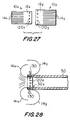
- FIG. 27 is a simplified elevational view somewhat like FIG. 3 showing another illustrative embodiment of the invention.
- FIG. 28 is a simplified sectional view illustrating use of apparatus of the type shown in FIG. 27.
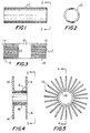
- a first step in processing tube 10 in accordance with the invention is to cut into it substantially axially at many locations 12 spaced circumferentially around each axial end portion as shown in FIG. 3. Cuts 12 reduce starting tube 10 to a plurality of fingers 14 extending substantially axially from each end of an uncut medial tube portion 16. Cuts 12 may be made by any suitable technique such as electron discharge machining ("EDM"), laser cutting, or etching.
- EDM electron discharge machining
- the length of medial portion 16 may be selected based on the intended use of the structure. For example, the length of medial portion 16 may be selected to correspond to the thickness of the patient's body tissue through which the medial portion will extend. Illustrative lengths for medial portion 16 are in the range from about 0.2 millimeters to about 4.0 millimeters.
- the length of fingers 14 may also be selected based on the intended use of the structure. Illustrative lengths for fingers 14 are in the range from about 1.0 millimeter to about 10.0 millimeters.
- FIGS. 4 and 5 show deflecting fingers 14 substantially radially out from the end of medial portion 16 that each finger is attached to.
- FIGS. 4 and 5 show the angle A between each finger 14 and the adjacent axially extending surface of medial portion 16 as approximately 90°, it will be understood that a wide range of angles A (e.g., in the range from about 45° to about 120°) can be used. Indeed, the angle of deflection of various fingers 14 can be different if desired.
- fingers 14 can be curved (e.g., concave curved as viewed from a plane extending radially out from medial portion 16) rather than straight if desired, and indeed outward curvature of the fingers can be used in place of outward deflection by a definite angle A.
- the free ends of the fingers 14 at one or both ends can curve toward or even overlap the free ends of the fingers at the other end.
- FIG. 6 and some subsequent FIGS. show examples of such curvature of fingers 14.
- FIG. 17 shows an example of overlapping fingers 14. In general, however, fingers 14 will be deflected so that they have at least a component of radially outward extension from medial portion 16.
- fingers 14 extend radially out from medial portion 16, even though it will be understood that this wording includes (1) fingers having only a component of such radially outward extension, and (2) fingers that are either substantially straight or curved.
- it might be desirable at this stage in the manufacturing process to deflect fingers 14 more than is shown in FIG. 4 (e.g., to angle A 60°) to increase the security with which fingers 14 will engage tissue surrounding medial portion 16.
- fingers 14 are deflected to (or at least to) approximately their intended final positions, it being understood that this wording includes deflecting fingers beyond the actual intended final positions.
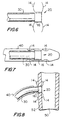
- FIGS. 6-8 show use of a structure of the type shown in FIGS. 4 and 5 to provide a connector 20 for an end of graft conduit 30.
- Graft conduit 30 may be natural conduit (e.g., a relocated portion of the patient's tubular body tissue), artificial conduit or a composite of natural and artificial conduits.
- an axial end portion of graft conduit 30 is inserted substantially coaxially into and attached to medial portion 16.
- graft conduit 30 may be secured together by any suitable means such as suturing, adhesive, welding, etc.
- the next step in use of the graft 30 and connector 20 is to insert that assembly into a delivery tube 40, not part of the invention as shown in FIG. 7.
- Tube 40 is preferably slightly larger in diameter than medial portion 16 or graft conduit 30.
- fingers 14 are resiliently deflected back toward their initial positions as axial extensions from the ends of medial portion 16 as shown in FIG. 7. In other words, fingers 14 are elastically deflected inwardly toward parallelism with a central longitudinal axis of medial portion 16. If connector 20 is made of nitinol, temporary super-cooling of the connector may be used at this stage to facilitate assembly of components 20 and 30 in delivery tube 40 (assuming that graft conduit 30 can tolerate proximity to super-cooled connector 20).
- flexibility of medial portion 16 may allow a connector or plug to be resiliently circumferentially compressed to a relatively small size to facilitate delivery of the connector or plug to an installation site (e.g., delivery through the lumen of a patient's body conduit). After the connector or plug has been delivered to the desired site in the patient's body in its circumferentially compressed size, the connector or plug is released from the delivery apparatus so that it can automatically return to its original larger size.
- perforation of medial portion 16 may allow the tissue of the graft and conduit to which the graft is connected to grow together through the perforations.
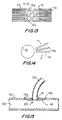
- FIG. 14 shows that the free ends of fingers 14 can be sharply pointed as indicated at 14a to facilitate engagement and or penetration of tissue by the fingers. This can be done, for example, by sharpening the associated axial end of the starting tube 10 to a sharp annular edge prior to making cuts 12 as shown in FIG. 3.
- the fingers 14 on the inside of conduit 50 may be longer, curved and sharply pointed for tissue penetration, and barbed as at 14b, while the fingers 14 on the outside of conduit 50 may be shorter, straighter, blunter, not barbed, and therefore not as adapted for tissue penetration.
- Such differences between the inner and outer fingers 14 may reflect different performance characteristics needed of them. Fluid pressure inside conduits 30 and 50 may attempt to force conduit 30 away from conduit 50, thereby necessitating relatively strong inner fingers 14. Concomitantly, there may be little tendency of conduit 30 to extend farther into conduit 50, so that outer fingers 14 can be relatively weak.
- Other differences that can be made between inner and outer fingers 14 include differences in number, spacing, width, etc.
- FIG. 17 illustrates another possibility mentioned earlier; namely, that the fingers 14 extending from axially opposite ends of medial portion 16 may be deflected and set so that their free ends overlap.
- this construction of fingers 14 helps to increase the contact area between fingers 14 and the tissue between them, as well as compression of the tissue between the fingers.
- FIG. 23 illustrates another point that has already been mentioned briefly; namely, that an end of a connector of this invention can have an angle other than 90° to the longitudinal axis of the connector.
- the left-hand end of the connector is not perpendicular to the longitudinal axis of the connector.
- This type of connector may be particularly suitable for connecting a graft conduit to the sidewall of another conduit at an angle which is not perpendicular to the longitudinal axis of the other conduit.
- FIG. 25 shows another example of a structure 100 for releasably confining fingers 14 on a connector.
- structure 100 is an elongated tube or rod which extends axially through the connector.
- a somewhat enlarged head 102 on one end of structure 100 includes a recess 104 for releasably receiving the free ends of the fingers 14 at one end of medial portion 16.
- recess 104 defines a collar 106 that extends annularly around the adjacent free ends of fingers 14.
- Fingers 14 may be resiliently deflected substantially parallel to the longitudinal axis of conduit 30 and away from the region of holes 120 if that will facilitate assembly of structures 10x and 10y on conduit 30.
- the assembly of structures 10x, 10y, and 30 may be delivered to and installed at a graft site in a patient in the same manner as is described above for any of the other connector embodiments.
- FIGS. 27 and 28 Structures of the type shown in FIGS. 27 and 28 are also usable to make plugs in accordance with this invention.
- a structure like 10x may be assembled with a structure like 10y generally as shown in FIG. 28, but without graft conduit 30.
- the interior of the assembly would be occluded by a plugging material or structure, generally as shown at 70 in FIG. 9, to produce a completed plug.
- a plugging material or structure generally as shown at 70 in FIG. 9, to produce a completed plug.
- Such a plug would be installed as described above for any of the other plug embodiments.
Abstract
Description
- This invention relates to structures that can be used to make connections between tubular medical grafts and a patient's tubular body conduits. The structures of the invention can alternatively be constructed for use as medical plugs (e.g., to close atrial or ventricular septal defects). The invention also relates to methods for making the structures mentioned above.
- Tubular grafts are frequently needed in medical procedures. For example, a coronary bypass procedure may involve the installation of a tubular graft between an aperture that has been formed in the side wall of the aorta and an aperture that has been formed in the side wall of a coronary artery downstream from an occlusion or blockage in that artery. Each end of the graft must be connected to the side wall of either the aorta or the coronary artery. Each such connection must extend annularly around the associated end of the graft conduit and be fluid-tight so that no blood will leak out. One common way to produce such connections is by suturing. It will be appreciated, however, that making such connections by suturing can be extremely difficult, time-consuming, and dependent on the skill of the physician for the quality of the results. There is also increasing interest in less invasive procedures which tend to impose constraints on the physician's access to the sites at which graft connections must be made and thereby make it more difficult or even impossible to use suturing to make such connections
Various types of mechanical connectors have been developed to reduce or eliminate the need for suturing, but improvements are constantly sought for such mechanical connectors with respect to considerations such as ease and speed of use, ease of manufacture, strength and permanence of the resulting connection, etc. - WO-A-98 03118 shows a connecting device made of a tubular sleeve. An end portion of said sleeve is provided with a plurality of axial slots and ribs. Said ribs can be flexed from their axial position to a radial position.
- Plugs are also needed in a variety of medical procedures. For example, it may be necessary to plug an atrial or ventricular septal defect in the heart of a new-born child. Again, improvements are constantly sought for plugs which can be easily and quickly installed using minimally invasive procedures.
- In view of the foregoing, it is an object of this invention to provide improved and simplified graft connectors.
- It is another object of this invention to provide improved and simplified medical plugs.
- It is still another object of this invention to provide improved and simplified methods of making structures that can be used as either medical graft connectors or plugs.
- These and other objects of the invention are accomplished in accordance with the principles of the invention by providing a connector or plug structure preferably formed by starting from a tube of highly elastic material such as nickel and titanium alloy (nitinol) metal. Each end portion of the tube is cut substantially axially at numerous locations spaced circumferentially around the tube to produce a plurality of fingers that extend substantially axially from each end of a remaining medial portion of the tube. The fingers at each end of the medial portion are then deflected so that they extend substantially radially out from the medial portion, and the fingers are set (e.g., by a heat treatment) in that deflected condition. For use of the structure as a graft connector, the medial portion is attached substantially coaxially to an end portion of a graft conduit. For use of the structure as a plug the medial portion of the tube is filled with a suitable plugging material or structure.
- To install the graft connector or plug in a patient the fingers at each axial end of the medial portion may be elastically deformed back toward their initial condition (in which the fingers extend substantially axially from the ends of the medial portion). The structure may then be inserted in a delivery tube, which may maintain the fingers in their substantially axially extending condition. The delivery tube may then be inserted through the aperture in the side wall of the patient's tubular body conduit to which the end of the graft conduit is to be attached, or through the aperture in the patient's tissue structure that is to be plugged. The delivery conduit may then be removed from around the connector or plug structure. This releases the fingers at each end of the medial portion to spring out on respective opposite sides of the tissue structure to which the connection is to be made, or to which the plug is to be applied.
- In some cases fingers may only be formed in one end of a starting tube. A connector may then be provided using two such tubes concentric with one another and with a graft conduit. In such an assembly the fingers on the two tubes extend from generally opposite axial ends of the assembly. Two such tubes may be similarly used to make a plug, although in this case the graft conduit is omitted and the interior of the structure is filled with a plugging material or structure.
- As an alternative or addition to use of a delivery tube to releasably hold the fingers substantially parallel to the longitudinal axis of a connector or plug, another structure may be removably placed around the fingers. Examples of such another structure include a collar or a strand of material such as wire or suture material.
- Further features of the invention, its nature and various advantages will be more apparent from the accompanying drawings- and the following detailed description of the preferred embodiments.
- FIG. 1 is a side elevational view of an illustrative embodiment of a starting component for a structure of this invention.
- FIG. 2 is an end elevational view of the component of FIG. 1.
- FIG. 3 is a side elevational view of the FIG. 1 component after some processing in accordance with the invention.
- FIG. 4 is a sectional view of the FIG. 5 component after further processing in accordance with the invention.
- FIG. 5 is an end elevational view of the FIG. 4 component.
- FIG. 6 is a simplified side elevational view of the FIG. 4 component with a graft conduit added so that the FIG. 4 component can be used as a connector for the graft conduit.
- FIG. 7 is a simplified, partly cut away, side elevational view of the FIG. 6 assembly in illustrative apparatus for use in installing the FIG. 6 assembly in a patient (not part of the invention).
- FIG. 8 illustrates use of the FIG. 7 apparatus to install the FIG. 6 assembly in a patient.
- FIG. 9 is a simplified sectional view of the FIG. 4 component with plug material or structure added so that the FIG. 4 component can be used as a plug.
- FIG. 10 is a view similar to FIG. 7, but for the plug embodiment of FIG. 9.
- FIG. 11 is a view somewhat like FIG. 8, but for the plug embodiment of FIGS. 9 and 10.
- FIG. 12 is another view somewhat like FIG. 11, but showing a fully installed plug of the type shown in FIG. 9.
- FIG. 13 is another view similar to FIG. 3 showing an illustrative modification of a FIG. 3 type structure in accordance with the invention.
- FIG. 14 is another view similar to a portion of FIG. 5 showing an illustrative modification of a FIG. 5 type structure in accordance with the invention.
- FIG. 15 is a sectional view somewhat like FIG. 8 showing illustrative modifications in accordance with the invention.
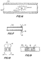
- FIG. 16 is a simplified sectional view showing still other illustrative modifications in accordance with the invention.
- FIG. 17 is a simplified sectional view showing an assembly similar to the assembly shown in FIG. 6, but with an illustrative modification in accordance with the invention.
- FIG. 18 is a simplified sectional view somewhat like FIG. 4 which is useful in explaining an illustrative modification in accordance with this invention.
- FIG. 19 is a view somewhat like FIG. 7 or FIG. 10 for the modified structure of FIG. 18.
- FIG. 20 is a simplified sectional view showing an illustrative precursor structure for embodiments of the type illustrated by FIGS. 18 and 19.
- FIG. 21 is a simplified elevational view showing another illustrative precursor structure for embodiments of the type illustrated by FIGS. 18 and 19.
- FIG. 22 is a simplified sectional view similar to FIG. 15 showing other illustrative modifications in accordance with the invention.
- FIG. 23 is a simplified elevational view similar to FIG. 3 showing more illustrative modifications in accordance with the invention.
- FIG. 24 is another simplified elevational view similar to FIG. 3 showing still more illustrative modifications in accordance with the invention.
- FIG. 25 is a simplified sectional view showing an illustrative alternative to apparatus of the type shown in FIG. 7 in accordance with the invention.
- FIG. 26 is a simplified elevational view illustrating another possible modification of structures in accordance with the invention.
- FIG. 27 is a simplified elevational view somewhat like FIG. 3 showing another illustrative embodiment of the invention.
- FIG. 28 is a simplified sectional view illustrating use of apparatus of the type shown in FIG. 27.
- An illustrative starting component for the connector or plug structures of this invention is a
hollow tube 10 as shown in FIGS. 1 and 2.Tube 10 may have any length, diameter, and wall thickness suitable for the intended use of the finished connector or plug structure. For use as a cardiac bypass graft connector, for example,tube 10 may have a diameter of about 4.0 millimeters, a wall thickness of about 0.0762 mm (0.003 inches), and a length of about 7.0 millimeters. It will be understood, however, that these specific dimensions are only exemplary, and that any other dimensions can be used instead if desired. The material oftube 10 is preferably highly elastic. A particularly preferred material is nickel titanium alloy (nitinol) metal (which can be per se conventional), but other materials such as stainless steel or thermoplastics can be used instead if desired. - A first step in processing
tube 10 in accordance with the invention is to cut into it substantially axially atmany locations 12 spaced circumferentially around each axial end portion as shown in FIG. 3.Cuts 12reduce starting tube 10 to a plurality offingers 14 extending substantially axially from each end of an uncutmedial tube portion 16.Cuts 12 may be made by any suitable technique such as electron discharge machining ("EDM"), laser cutting, or etching. The length ofmedial portion 16 may be selected based on the intended use of the structure. For example, the length ofmedial portion 16 may be selected to correspond to the thickness of the patient's body tissue through which the medial portion will extend. Illustrative lengths formedial portion 16 are in the range from about 0.2 millimeters to about 4.0 millimeters. The length offingers 14 may also be selected based on the intended use of the structure. Illustrative lengths forfingers 14 are in the range from about 1.0 millimeter to about 10.0 millimeters. - The next step is to deflect
fingers 14 to approximately the positions that it is desired for them to have in the finished and installed connector or plug structure. For example, FIGS. 4 and 5show deflecting fingers 14 substantially radially out from the end ofmedial portion 16 that each finger is attached to. Although FIGS. 4 and 5 show the angle A between eachfinger 14 and the adjacent axially extending surface ofmedial portion 16 as approximately 90°, it will be understood that a wide range of angles A (e.g., in the range from about 45° to about 120°) can be used. Indeed, the angle of deflection ofvarious fingers 14 can be different if desired. In addition,fingers 14 can be curved (e.g., concave curved as viewed from a plane extending radially out from medial portion 16) rather than straight if desired, and indeed outward curvature of the fingers can be used in place of outward deflection by a definite angle A. For example, the free ends of thefingers 14 at one or both ends can curve toward or even overlap the free ends of the fingers at the other end. FIG. 6 and some subsequent FIGS. show examples of such curvature offingers 14. FIG. 17 shows an example of overlappingfingers 14. In general, however,fingers 14 will be deflected so that they have at least a component of radially outward extension frommedial portion 16. For convenience and simplicity herein it will therefore sometimes be said thatfingers 14 extend radially out frommedial portion 16, even though it will be understood that this wording includes (1) fingers having only a component of such radially outward extension, and (2) fingers that are either substantially straight or curved. - It will also be appreciated that it may be desirable to deflect
fingers 14 beyond their desired final positions so that when they are subsequently released during deployment, they will resiliently bear on the tissue in which the connector or plug is installed in their effort to return to the positions to which they have been deflected in this step of their manufacture. For example, if FIG. 4 shows the desired final position offingers 14 in use in a patient (i.e., angle A = 90°), it might be desirable at this stage in the manufacturing process to deflectfingers 14 more than is shown in FIG. 4 (e.g., to angle A = 60°) to increase the security with whichfingers 14 will engage tissue surroundingmedial portion 16. Nevertheless, for convenience and simplicity herein it will sometimes be said that in thismanufacturing step fingers 14 are deflected to (or at least to) approximately their intended final positions, it being understood that this wording includes deflecting fingers beyond the actual intended final positions. - When
fingers 14 have been deflected to approximately their final intended positions (e.g., as shown in FIGS. 4 and 5),fingers 14 are set in those positions. For example, a heat treatment may be applied to the structure to setfingers 14 in their deflected positions. - FIGS. 6-8 show use of a structure of the type shown in FIGS. 4 and 5 to provide a
connector 20 for an end ofgraft conduit 30. (The possible alternative use of structures of the type shown in FIGS. 4 and 5 as a plug rather than a graft connector will be discussed after explanation of the connector embodiment is substantially complete.)Graft conduit 30 may be natural conduit (e.g., a relocated portion of the patient's tubular body tissue), artificial conduit or a composite of natural and artificial conduits. - In the illustrative embodiment shown in FIG. 6 an axial end portion of
graft conduit 30 is inserted substantially coaxially into and attached tomedial portion 16. Depending on the materials ofcomponents - The next step in use of the
graft 30 andconnector 20 is to insert that assembly into adelivery tube 40, not part of the invention as shown in FIG. 7.Tube 40 is preferably slightly larger in diameter thanmedial portion 16 orgraft conduit 30. To fitstructure 20 intotube 40fingers 14 are resiliently deflected back toward their initial positions as axial extensions from the ends ofmedial portion 16 as shown in FIG. 7. In other words,fingers 14 are elastically deflected inwardly toward parallelism with a central longitudinal axis ofmedial portion 16. Ifconnector 20 is made of nitinol, temporary super-cooling of the connector may be used at this stage to facilitate assembly ofcomponents graft conduit 30 can tolerate proximity to super-cooled connector 20). Super-cooling nitinol makes it very plastic so thatfingers 14 can be straightened out and so that they will hold that shape for insertion ofcomponents tube 40. Whenconnector 20 warms up again, it "remembers" the shape it was given during the step in which the fingers were set after being radially outwardly deflected. - The next step in use of the assembly shown in FIG. 7 is to insert
delivery tube 40 through an aperture in the side wall of the patient's tubular body conduit (50 in FIG. 8) to whichgraft conduit 30 is to be connected byconnector 20. For example, a tapered distal end portion of delivery tube 40 (shown on the right in FIG. 7) may be used to helptube 40 enter the aperture in tubular bodyconduit side wall 52.Elements side wall 52 so thatmedial portion 16 is approximately centered onside wall 52. This places thefingers 14 at one axial end ofmedial portion 16 insideconduit 50, while thefingers 14 at the other end ofmedial portion 16 areoutside conduit 50. - The next step is illustrated by FIG. 8 and involves the withdrawal of
delivery tube 40 from the aperture inside wall 52, whilecomponents side wall 52. Asdelivery tube 40 is thus withdrawn, thefingers 14 on the inside ofconduit 50 are gradually released to resiliently spring out insideside wall 52 around the aperture through that wall. Thereafter, asdelivery tube 40 continues to be retracted, thefingers 14 on the outside ofconduit 50 are also released to resiliently spring out outsideside wall 52 around the aperture through that wall. Thus the final condition ofconnector 20 is as shown in FIG. 8 (although ofcourse delivery tube 40 is ultimately completely withdrawn from the patient). Thefingers 14 on the inside ofconduit 50 prevent the connector and graft conduit from pulling out of the aperture inside wall 52. Thefingers 14 on the outside ofconduit 50 prevent the connector and graft conduit from protruding undesirably far intoconduit 50. - Although FIGS. 7 and 8
show inserting connector 20 into the aperture in theside wall 52 ofconduit 50 from outside that conduit,connector 20 could alternatively be inserted from inside the lumen ofconduit 50. In thatcase connector 20 would typically be located at a medial position indelivery tube 40, withgraft conduit 30 extending from the connector in the distal direction along the interior oftube 40.Tube 40 would then be inserted intraluminally intoconduit 50 until the location of the aperture inwall 52 is reached.Tube 40 would then be passed out of the aperture inwall 52 untilmedial portion 16 is centered onwall 52.Components conduit 50 whiletube 40 is pulled back proximally via the lumen ofconduit 50, thereby exposinggraft conduit 30outside conduit 50 and similarly exposingconnector 20 so thatfingers 14 can spring out and engage the inner and outer surfaces ofside wall 52 around the aperture in that side wall. A separate axially extending pusher or holder structure may be needed insidetube 40 to help holdcomponents tube 40 is pulled back proximally. - FIG. 9 shows an alternative embodiment in which a structure of the type shown in FIGS. 4 and 5 is adapted for use as a
plug 60. In this alternativemedial portion 16 is substantially filled or occluded with a plug material orstructure 70 such as silicone or thermoplastic.Plug 60 is then inserted in adelivery tube 40 as shown in FIG. 10 in substantially the same way thattube 40 is used withcomponent 20 in FIG. 7. - The next step in the use of
assembly 40/60 is to inserttube 40 through the aperture in thetissue structure 80 that is to be plugged as shown in FIG. 11. As in the previously described connector embodiment,assembly 40/60 is preferably positioned relative totissue structure 80 so that thefingers 14 extending from one axial end ofmedial portion 16 are on one side ofstructure 80, and so that thefingers 14 extending from the other axial end ofmedial portion 16 are on the other side ofstructure 80. - The next step is to withdraw
tube 40 from the aperture intissue structure 80, while holdingplug 60 substantially stationary relative to structure 80. To holdplug 60 stationary in this manner, a holder tube (not shown) may be inserted intotube 40 until the distal end of the holder tube bears onplug structure 70. Then the holder tube can be held stationary relative totissue structure 80 whiletube 40 is withdrawn. Astube 40 is withdrawn, thefingers 14 on the right-hand side ofstructure 80 as viewed in FIGS. 11 and 12 are gradually released to spring resiliently out against that side ofstructure 80. Further withdrawal oftube 40 allows the fingers on the left-hand side ofstructure 80 to spring resiliently out against that side ofstructure 80. The completed plug installation is as shown in FIG. 12. - As in the case of
connector 20, plug 60 can be inserted into the aperture intissue structure 80 from either side of that tissue structure, andtube 40 can similarly be withdrawn in either direction. For example, iftissue structure 80 is the wall of a conduit or chamber, plug 60 can be installed from either the inside or outside of that conduit or chamber, andtube 40 can be withdrawn via either the inside or outside of that conduit or chamber. - Manufacture of the connector or plug structures described above is greatly facilitated by the fact that
elements Elements small fingers 14 on another component. Use of the connector or plug structures of this invention is extremely easy because all that is required is to properly position the connector or plug relative to the appropriate tissue of the patient and then withdraw thedelivery tube 40 from around the connector or plug.Fingers 14 automatically spring out into the positions required to complete and secure the connector or plug. - If desired,
medial portion 16 can be perforated at any suitable time during the course of manufacturing a connector or plug in accordance with this invention. For example, FIG. 13 showsmany perforations 16b inmedial portion 16, thereby effectively reducing the medial portion to an open mesh ofmembers 16a. Such perforation ofmedial portion 16 may increase its flexibility (e.g., axially and radially) and therefore its long-term acceptability in the patient's body. The radial compliance of a flexible connector or plug (i.e. the ability of such a structure to resiliently increase or decrease in circumference) is believed to be beneficial with respect to long-term body circuit lumen patency. Increased flexibility and radial compliance ofmedial portion 16 may also facilitate delivery and/or installation of the connector or plug. For example, flexibility ofmedial portion 16 may allow a connector or plug to be resiliently circumferentially compressed to a relatively small size to facilitate delivery of the connector or plug to an installation site (e.g., delivery through the lumen of a patient's body conduit). After the connector or plug has been delivered to the desired site in the patient's body in its circumferentially compressed size, the connector or plug is released from the delivery apparatus so that it can automatically return to its original larger size. In the case of a connector for a natural tissue graft, perforation ofmedial portion 16 may allow the tissue of the graft and conduit to which the graft is connected to grow together through the perforations. - Perforation of
medial portion 16 may also allow that portion of a connector or plug to exert resilient, radially outward force on surrounding tissue on a long-term basis after the connector or plug has been installed. This may be useful for such purposes as firmer engagement of the surrounding tissue, reduced potential for fluid leakage around the connector or plug, etc. For example, if the elastic recoil of the surrounding tissue diminishes over time or if the tissue is relatively non-elastic due to disease or age, sealing between the tissue and the connector or plug may be reduced. In such cases, resilient outward expansion of the connector or plug can be helpful in compensating for deficiencies of the tissue. A connector or plug with a perforatedmedial portion 16 can resiliently expand to fill any opening that may otherwise tend to develop betweenportion 16 and the surrounding tissue if and when the elastic recoil of the tissue diminishes. - Whereas the depicted connector and plug embodiments are round, other shapes (e.g., ellipses, polygons, etc.) are equally possible. Similarly, the ends of
medial portion 16 do not have to be perpendicular to the longitudinal axis of the connector or plug structure. Particularly in the case of connectors, it may be desired to have one or both ends ofmedial portion 16 skewed relative to the longitudinal axis of the connector (i.e., so that the longitudinal axis is not perpendicular to a plane defined by the skewed end of medial portion 16). The free ends of theadjacent fingers 14 may then be similarly skewed. Such skewing of portions of the connector may facilitate connecting the end of a graft to the side wall of a patient's body conduit at an angle other than 90° to that side wall. These and other illustrative examples of modifications, alternatives, and enhancements in accordance with the invention will now be discussed in more detail with reference to FIGS. 14-28. - FIG. 14 shows that the free ends of
fingers 14 can be sharply pointed as indicated at 14a to facilitate engagement and or penetration of tissue by the fingers. This can be done, for example, by sharpening the associated axial end of the startingtube 10 to a sharp annular edge prior to makingcuts 12 as shown in FIG. 3. - FIG. 15 shows the free ends of the
fingers 14 that are generally on the inside ofconduit 50 penetrating and passing through theconduit wall 52 to more firmlysecure connector 20 toconduit 50. In addition, FIG. 15 shows that the free ends of the above-mentionedfingers 14 may be provided withbarbs 14b (somewhat like the barbs on fishing hooks) that strongly resist withdrawal of the fingers after the fingers have penetrated the tissue ofconduit wall 52. FIG. 15 still further shows that thefingers 14 on the inside ofconduit 50 in a finished connection may be different from thefingers 14 on the outside ofconduit 50. For example, thefingers 14 on the inside ofconduit 50 may be longer, curved and sharply pointed for tissue penetration, and barbed as at 14b, while thefingers 14 on the outside ofconduit 50 may be shorter, straighter, blunter, not barbed, and therefore not as adapted for tissue penetration. Such differences between the inner andouter fingers 14 may reflect different performance characteristics needed of them. Fluid pressure insideconduits conduit 30 away fromconduit 50, thereby necessitating relatively stronginner fingers 14. Concomitantly, there may be little tendency ofconduit 30 to extend farther intoconduit 50, so thatouter fingers 14 can be relatively weak. Other differences that can be made between inner andouter fingers 14 include differences in number, spacing, width, etc. - FIG. 16 illustrates a point made earlier; namely, that a connector or plug in accordance with this invention can have a cross sectional shape other than round. In the particular example shown in FIG. 16 the connector or plug has an elliptical cross section, with the major axis of the ellipse substantially aligned with the longitudinal axis of
conduit 50. In addition, FIG. 16 shows thatdifferent fingers 14 at either or both axial ends ofmedial portion 16 can have different lengths. In the particular example shown in FIG. 16 thefingers 14 that are more nearly aligned with the longitudinal axis ofconduit 50 are longer than the fingers that are more nearly perpendicular to the longitudinal axis ofconduit 50. To producefingers 14 of different lengths, one or both axial ends of the startingtube 10 can be appropriately shaped prior to makingcuts 12, or the free ends of the fingers can be trimmed aftercuts 12 have been made. - FIG. 17 illustrates another possibility mentioned earlier; namely, that the
fingers 14 extending from axially opposite ends ofmedial portion 16 may be deflected and set so that their free ends overlap. When a connector or plug made in this way is installed in a patient, this construction offingers 14 helps to increase the contact area betweenfingers 14 and the tissue between them, as well as compression of the tissue between the fingers. - It may desirable to make
fingers 14 so that their flexural stiffness (especially in directions radial of medial portion 16) varies in a predetermined way along the length of each finger. This feature can be used, for example, to cause the fingers to assume a more nearly cylindrical shape when they are deflected for insertion into adelivery tube 40. Thus FIG. 18 shows a connector or plug which makes use of this possible feature prior to insertion into a delivery tube, and FIG. 19 shows the FIG. 18 structure after insertion intodelivery tube 40. A comparison of FIGS. 7 or 10, on the one hand, with FIG. 19, on the other hand, reveals that in FIG. 19fingers 14 form a more nearly cylindrical array at each axial end ofmedial portion 16 because the flexural stiffness of the fingers in FIGS. 18 and 19 has been tailored to produce this result. - FIGS. 20 and 21 show illustrative techniques for tailoring the flexural stiffness of
fingers 14 along their length as mentioned above in connection with FIGS. 18 and 19. In FIG. 20 the thickness of the wall of the starting tube 10' is varied along the length of the tube to givefingers 14 correspondingly varied thickness along their lengths. In FIG. 21fingers 14 are cut so that their width varies along their length. If desired both techniques (FIG. 20 and FIG. 21) can be combined. In general terms, the geometry offingers 14 can be tailored in any suitable way to causefingers 14 to exhibit any desired elastic behavior. - FIG. 22 illustrates another technique for attaching natural or
artificial graft conduit 30 to a connector in accordance with this invention. As shown in FIG. 22 thefingers 14 at one end ofmedial portion 16 are made to pass through (e.g., by piercing) an annular end portion ofgraft conduit 30. When the connector and graft are installed in the patient through an aperture in the patient'sbody tissue wall 52, thesefingers 14 curve back to contact one surface ofwall 52, while thefingers 14 at the other end ofmedial portion 16 curve back to contact the other surface ofwall 52. - FIG. 23 illustrates another point that has already been mentioned briefly; namely, that an end of a connector of this invention can have an angle other than 90° to the longitudinal axis of the connector. In the example shown in FIG. 23 the left-hand end of the connector is not perpendicular to the longitudinal axis of the connector. This type of connector may be particularly suitable for connecting a graft conduit to the sidewall of another conduit at an angle which is not perpendicular to the longitudinal axis of the other conduit.
- FIG. 24 illustrates a technique that may be used to releasably hold
fingers 14 in a desired configuration prior to deployment of a connector or plug in a patient. In this embodiment the free end portion of eachfinger 14 near one end of the connector or plug has a hole 14c through it. Awire 90 or other suitable material strand is threaded through these holes and formed into a loop that holds the fingers in a desired condition (in this case, a substantially cylindrical extension of medial portion 16). Whenloop 90 is undone and pulled out of holes 14c, the associatedfingers 14 are released to spring radially out (e.g., as shown in FIG. 8 or FIG. 12). This type of releasable retention offingers 14 can be used in place of or in addition to retention inside a delivery tube (e.g.,tube 40 in FIG. 7 or 10) to facilitate control of the associated fingers until it is desired to fully deploy them. For example, such releasable confinement and control offingers 14 may be useful to facilitate intraluminal delivery and deployment of a connector or plug. - FIG. 25 shows another example of a
structure 100 for releasably confiningfingers 14 on a connector. In thiscase structure 100 is an elongated tube or rod which extends axially through the connector. A somewhatenlarged head 102 on one end ofstructure 100 includes arecess 104 for releasably receiving the free ends of thefingers 14 at one end ofmedial portion 16. In other words,recess 104 defines acollar 106 that extends annularly around the adjacent free ends offingers 14. Whenfingers 14 are thus received inrecess 104 orcollar 106, they are prevented from springing radially outwardly. However, whenfingers 14 are released fromrecess 104 or collar 106 (e.g., by shiftingstructure 100 to the left relative to the other elements shown in FIG. 25), the fingers are free to resiliently spring radially outwardly.Structure 100 can then be removed (e.g., by pulling it back to the right as viewed in FIG. 25).Head 102 may additionally be sharply pointed as shown in FIG. 25 to act as an incisor and/or dilator for helping the structure to pass through a patient's body tissue wall prior to release offingers 14 fromrecess 104 orcollar 106.Structure 100 may be adapted for passage into a patient along a guide wire previously installed in the patient. For example,structure 100 may have a central, axially extending bore or lumen through which such a guide wire may pass. A central, axially extending guide structure may similarly be used with embodiments like the one shown in FIG. 7. - FIG. 26 shows possible modification of a connector in accordance with the invention to include a
web 110 of a highly elastic material such as silicone betweenadjacent fingers 14. Such aweb 110 can be provided on thefingers 14 at either or both ends ofmedial portion 16. Possible benefits ofweb 110 include enhanced sealing and faster clotting. If desired, a clot-enhancing or clot-promoting material or drug can be added toweb 110. - Although not always specifically mentioned above, it will be understood that many of the features shown in FIGS. 14-26 are applicable to plugs as well as to graft connectors.
- FIGS. 27 and 28 show an alternative embodiment in which a connector is assembled from two initially
separate parts parts part 10y is somewhat larger than the diameter of the tube used to formpart 10x.Fingers Holes medial portion fingers 14 and the holes 120 of that tube. Thefingers 14 on each tube are treated as described above for other embodiments (i.e., the fingers are deflected radially out and set in that condition). -
Structures graft conduit 30 as shown in FIG. 28. In particular, the perforated and medial portions ofstructure 10y are placed substantially concentrically around the outside ofgraft conduit 30, whilestructure 10x is placed substantially concentrically inside the graft conduit.Structures fingers 14 are oppositely directed along the longitudinal axis ofgraft conduit 30.Structures sutures 130 through radiallyadjacent holes structures Fingers 14 may be resiliently deflected substantially parallel to the longitudinal axis ofconduit 30 and away from the region of holes 120 if that will facilitate assembly ofstructures conduit 30. The assembly ofstructures - Connectors of the type shown in FIGS. 27 and 28 may have the advantage that, even though one
component 10x is insideconduit 30, that component can be radially recessed intoconduit 30 as indicated at 30x, thereby leaving a substantially smooth passageway for fluid flow throughconduit 30 and the connector. Such a smooth passageway is desirable for such purposes as avoiding any obstruction or disturbance (e.g., by causing turbulence) of the fluid flow. The recessing at 30x can be produced by clamping the tissue between the tubular portions ofcomponents - In some applications it might be possible to use only one structure like 10x or 10y in a graft connector. For example, it might be possible to eliminate
structure 10y from FIG. 28. In addition, ifstructure 10y is eliminated from FIG. 28, the assembly shown in FIG. 28 could be further modified by placingstructure 10x outside rather than inside the end ofgraft conduit 30. Any of the modifications and/or enhancements described above for other connector embodiments can also be applied to connectors of the type shown in FIGS. 27 and 28. - Structures of the type shown in FIGS. 27 and 28 are also usable to make plugs in accordance with this invention. For example, a structure like 10x may be assembled with a structure like 10y generally as shown in FIG. 28, but without
graft conduit 30. The interior of the assembly would be occluded by a plugging material or structure, generally as shown at 70 in FIG. 9, to produce a completed plug. Such a plug would be installed as described above for any of the other plug embodiments. - It will be understood that the foregoing is only illustrative of the principles of the invention, and that still other modifications can be made by those skilled in the art without departing from the scope of the invention. For example, the various materials and dimensions mentioned herein are only examples, and other materials and dimensions can be used if desired. As another example of modifications within the scope of the invention, as an alternative to starting with a tube like
tube 10 in FIGS. 1 and 2, one could start with a web of any material that would be suitable fortube 10. Two opposite marginal portions of the web would then be cut at numerous substantially parallel locations (somewhat likecuts 12 in FIG. 3), leaving an uncut medial web portion. Medial web portion would then be formed into a medial tube portion (like 16 in FIG. 3), e.g., by forming it around a mandrel, with or without bonding of the resulting seam. The structure would then be substantially as shown in FIG. 3 and could be further processed and used to produce a connector or plug as described above in connection with any of the subsequent FIGS. Similar web rather than tube starting structures could be used for embodiments of the type shown in FIGS. 27 and 28.
Claims (55)
- A connector (20) for use in connecting an end of a tubular graft conduit (30) to a sidewall (52) of a patient's tubular body conduit (50) via an aperture in that side wall (52) comprising:a medial tubular portion (16, 16x, 26y) ; anda plurality of resilient fingers (14, 14x, 14y) integral with the medial tubular portion (16, 16x, 16y) and extending substantially radially out from an axial end of the medial tubular portion (16, 16x, 16y),wherein the fingers (14, 14x, 14y) are concave curved as viewed from a plane extending radially out from the medial tubular portion (16, 16x, 16y), and wherein the fingers (14, 14x, 14y are elastically deflectable inwardly toward parallelism with a central longitudinal axis of the medical tubular portion (16, 16x 16y).
- The connector (20) defined in claim 1 wherein the medial tubular portion (16, 16x, 16y) and the fingers (14, 14x, 14y) comprise nitinol.
- The connector (20) defined in claim 1 or 2, wherein the fingers (14, 14x, 14y) include fingers (14, 14x, 14y) that extend substantially radially out from each axial end of the medial tubular portion (16, 16x, 16y).
- The connector (20) defined in claim 1, 2 or 3, wherein the medial tubular portion (16, 16x, 16y) is perforated.
- The connector (20) defined in claim 4, wherein the perforations (16b) of the medial tubular portion (16, 16x, 16y) increase flexibility of the medial tubular portion (16, 16x, 16y).
- The connector (20) defined in claim 4, wherein the perforations (16b) of the medial tubular portion (16, 16x, 16y) increase radial flexibility of the medial tubular portion (16, 16x, 16y).
- The connector (20) defined in claim 4, 5 or 6, wherein the perforations (16b) of the medial tubular portion (16, 16x, 16y) provide sites for attachment of the connector (20) to the tubular graft conduit (30).
- The connector (20) defined in any one of claims 1 to 7, wherein end portions of the fingers (14, 14x, 14y) remote from the medial tubular portion (16, 16x, 16y) are pointed (14a).
- The connector (20) defined in any one of claims 1 to 8, wherein end portions of the fingers (14, 14x, 14y) remote from the medial tubular portion (16, 16x, 16y) are barbed (14b).
- The connector (20) defined in any one of claims 1 to 9, wherein the medial tubular portion (16, 16x, 16y) has a substantially round cross section.
- The connector (20) defined in any one of claims 1 to 10, wherein the medial tubular portion (16, 16x, 16y) has a substantially elliptical cross section.
- The connector (20) defined in any one of claims 1 to 11, wherein substantially all of the fingers (14, 14x, 14y) extending from an axial end of the medial tubular portion (16, 16x, 16y) are of substantially similar length.
- The connector (20) defined in any one of claims 1 to 11, wherein different ones of the fingers (14, 14x, 14y) extending from an axial end of the medial tubular portion (16, 16x, 16y) are of different lengths.
- The connector (20) defined in any one of claims 3 to 13, wherein the fingers (14, 14x, 14y) that extend from both axial ends of the medial tubular portion (16, 16x, 16y) are of substantially similar length.
- The connector (20) defined in any one of claims 3 to 13, wherein the fingers (14, 14x, 14y) that extend from one axial end of the medial tubular portion (16, 16x, 16y) are different in length from the fingers (14, 14x, 14y) that extend from the other axial end of the medial tubular portion (16, 16x, 16y).
- The connector (20) defined in any one of claims 11 to 15, wherein the elliptical cross section has a relatively large major axis and a relatively small minor axis, and wherein ones of the fingers (14, 14x, 14y) that extend radially out more nearly parallel to the major axis than to the minor axis are longer than others of the fingers (14, 14x, 14y) that extend radially out more nearly parallel to the minor axis than to the major axis.
- The connector (20) defined in any one of claims 3 to 16, wherein free end portions of the fingers (14, 14x, 14y) that extend from one axial end of the medial tubular portion (16, 16x, 16y) overlap free end portions of the fingers (14, 14x, 14y) that extend from the other axial end of the medial tubular portion (16, 16x, 16y).
- The connector (20) defined in any one of claims 1 to 17, wherein each finger (14, 14x, 14y) has different flexural stiffness radially of the medial tubular portion (16, 16x, 16y) at different points along the length of the finger (14, 14x, 14y).
- The connector (20) defined in any one of claims 1 to 18, wherein each finger (14, 14x, 14y) has different thickness at different points along its length.
- The connector (20) defined any one of claims 1 to 19 wherein each finger (14, 14x, 14y) has different width at different points along its length.
- The connector (20) defined in any one of claims 1 to 20, wherein the axial end of the medial tubular portion (16, 16x, 16y) defines a plane which is transverse but not perpendicular to a longitudinal axis of the medial tubular portion (16, 16x, 16y).
- The connector (20) defined in any one of claims 1 to 21, further comprising structure on free end portions of the fingers (14, 14x, 14y) and configured to facilitate releasable retention of the fingers (14, 14x, 14y) in a condition in which they extend substantially parallel to a longitudinal axis of the medial tubular portion (16, 16x, 16y).
- The connector (20) defined in claim 22 wherein the structure comprises an aperture (14c) through each of the fingers (14, 14x, 14y).
- The connector (20) defined in any one of claims 1 to 23 further comprising:an elastic web (110) between adjacent ones of the fingers (14, 14x, 14y).
- The connector (20) defined in claim 24 wherein the web (110) comprises silicone.
- The connector defined in any one of claims 1 to 25 further comprising:a second medial tubular portion (16y); anda second plurality of resilient fingers (14y) integral with the second medial tubular portion (16y) and extending radially out from an axial end of the second medial tubular portion (16y), the second medial tubular portion (16y) being configured to receive an axial end portion of the tubular graft conduit (30) substantially coaxially inside the second medial tubular portion (16y) with the medial tubular portion (16x) received substantially coaxially inside the axial end portion.
- The connector defined in claim 26, wherein the second medial tubular portion (16y) is further configured so that when the second medial tubular portion (16y) receives the axial end portion of the tubular graft conduit (30) with the medial tubular portion (16x) received substantially coaxially inside the axial end portion, the fingers (14x) on the medial tubular portion (16x) extend out of the axial end portion and the second fingers (14y) on the second medial tubular portion (16y) extend in a direction which is generally away from the fingers (14x) on the medial tubular portion (16x).
- The connector defined in claim 26 or 27, wherein the medial tubular portion (16x) and the second medial tubular portion (16y) include structures configured to facilitate securing those portions relative to one another.
- The connector defined in claim 28 wherein the structures are further configured to facilitate securing the medial tubular portion (16x) and the second medial tubular portion (16y) relative to the axial end portion.
- The connector defined in claim 28 or 29, wherein the structures comprise apertures (120x, 120y) through side walls of the medial tubular portion (16x) and the second medial tubular portion (16y).
- The connector defined in claim 30, wherein the apertures (120x, 120y) are configured to receive suture strands (130) passed through those apertures and the axial end portion.
- A graft assembly comprising:a tubular graft conduit (30); anda connector (20) as defined in any one of claims 1 to 31 substantially coaxially connected to an end portion of the tubular graft conduit (30).
- The graft assembly defined in claim 32, wherein the end portion of the tubular graft conduit (30) is disposed substantially coaxially inside the medial tubular portion (16, 16x, 16y).
- The graft assembly defined in claim 32 or 33, wherein the fingers (14, 14x, 14y) extend through a portion of the side wall (52) of the tubular graft conduit (30).
- A graft installing assembly comprising:a graft assembly as defined in claim 32, 33 or 34 anda delivery structure (100) extending substantially coaxially through the graft assembly and including a collar (106) configured to releasably retain the fingers (14, 14x, 14y) in a condition in which they extend substantially parallel to a longitudinal axis of the medial tubular portion (16, 16x, 16y).
- The graft installing assembly defined in claim 35, wherein the delivery structure (100) is axially shiftable relative to the graft assembly in order to shift the collar (106) out of engagement with the fingers (14, 14x, 14y) and thereby release the fingers (14, 14x, 14y) to extend substantially radially out from the medial tubular portion (16, 16x, 16y).
- The graft installation assembly defined in claim 35 or 36, wherein the delivery structure (100) includes a substantially conical tip (102) extending away from the fingers (14, 14x, 14y) and configured to facilitate entry of the graft assembly into an aperture in a patient's body tissue.
- The method of making a medical graft connector (20) comprising:providing a tube (10) of an elastic material;substantially axially cutting an axial end portion of the tube at a plurality of locations spaced circumferentially around the axial end portion to convert the axial end portion to a plurality of fingers (14, 14x, 14y) that extend substantially axially from an adjacent end of an uncut medial portion (16, 16x, 16y) of the tube (10);deflecting the fingers (14, 14x, 14y) substantially radially out from the medial portion (16, 16x, 16y), wherein the deflecting comprises concave curving the fingers (14, 14x, 14y) as viewed from a plane extending radially out from the medial portion (16, 16x, 16y); andsetting the fingers (14, 14x, 14y) as deflected in the deflecting,
wherein the fingers are elastically deflectable inwardly toward parallelism with a central longitudinal axis of the medial tubular portion - The method defined in claim 38 wherein the setting comprises:heat treating the fingers (14, 14x, 14y).
- The method defined in claim 38 or 39 further comprising:substantially axially cutting a second axial end portion of the tube (10) remote from the axial end portion at a second plurality of locations spaced circumferentially around the second axial end portion to convert the second axial end portion to a second plurality of second fingers (14, 14x, 14y) that extend substantially axially from an adjacent second end of the uncut medial portion (16, 16x, 16y) of the tube (10) ;deflecting the second fingers (14, 14x, 14y) substantially radially out from the medial portion (16, 16x, 16y); andsetting the second fingers (14, 14x, 14y) as deflected in the deflecting of the second fingers (14, 14x, 14y).
- The method defined in claim 38, 39 or 40, further comprising:perforating the medial portion (16, 16x, 16y).
- The method defined in any one of claims 38 to 41, further comprising:pointing free ends of the fingers (14, 14x, 14y).
- The method defined in any one of claims 38 to 42, further comprising:barbing free end portions of the fingers (14, 14x, 14y).
- The method defined in any one of claims 38 to 43, wherein the tube (10) is provided with a substantially round cross section.
- The method defined in any one of claims 38 to 44, wherein the tube (10) is provided with a substantially elliptical cross section.
- The method defined in any one of claims 40 to 45, wherein the deflecting of the fingers (14, 14x, 14y) and the deflecting of the second fingers (14, 14x, 14y) cause free end portions of the fingers (14, 14x, 14y) to overlap with free end portions of the second fingers (14, 14x, 14y).
- The method defined in any one of claims 38 to 46, wherein the tube (10) is provided with different wall thickness at different locations along its length.
- The method defined in any one of claims 38 to 47, wherein the cutting causes each finger (14, 14x, 14y) to have different width at different locations along its length.
- The method defined in any one of claims 38 to 48, wherein the tube (10) is provided with an axial end which is transverse but not perpendicular to a longitudinal axis of the tube (10).
- The method defined in any one of claims 38 to 49, further comprising:providing structure on free end portions of the fingers (14, 14x, 14y) configured to facilitate releasable retention of the fingers (14, 14x, 14y) in a condition in which they extend substantially parallel to a longitudinal axis of the medial portion (16, 16x, 16y).
- The method defined in any one of 38 claims to 50, further comprising:providing an elastic web (110) between adjacent ones of the fingers (14, 14x, 14y).
- The method defined in any one of claims 38 to 51, further comprising:providing a second tube (10) of an elastic material;substantially axially cutting an axial end portion of the second tube (10) at a second plurality of locations spaced circumferentially around the axial end portion of the second tube (10) to convert that axial end portion to a second plurality of second fingers (14y) that extend substantially axially from an adjacent end of an uncut second medial portion (16y) of the second tube (10);deflecting the second fingers (14y) substantially radially out from the second medial portion (16y);setting the second fingers (14y) as deflected in the deflecting of the second fingers (14y); andassembling the medial portion (16x) substantially concentrically inside an axial end section of a tubular graft conduit (30) and the second medial portion (16y) substantially concentrically outside the axial end section.
- The method defined in claim 52 wherein the assembling is performed so that the fingers (14x) extend out of the axial end section and so that the second fingers (14y) extend in a direction which is generally away from the fingers (14x) extending out of the axial end section.
- The method defined in claim 52 or 53 wherein the assembling comprises:securing the medial portion (16x) and the second medial portion (16y) relative to one another via the axial end section.
- The method defined in claim 54 wherein the securing comprises:suturing the medial portion (16x) and the second medial portion (16y) to one another through the axial end section.
Priority Applications (1)
| Application Number | Priority Date | Filing Date | Title |
|---|---|---|---|
| EP06003114.3A EP1685808B1 (en) | 1998-01-30 | 1998-12-18 | Device for use in closing septal defects and an installation assembly for such device |
Applications Claiming Priority (3)
| Application Number | Priority Date | Filing Date | Title |
|---|---|---|---|
| US1672198A | 1998-01-30 | 1998-01-30 | |
| US16721 | 1998-01-30 | ||
| PCT/US1998/026845 WO1999038454A2 (en) | 1998-01-30 | 1998-12-18 | Medical graft connector or plug structures, and methods of making and installing same |
Related Child Applications (1)
| Application Number | Title | Priority Date | Filing Date |
|---|---|---|---|
| EP06003114.3A Division EP1685808B1 (en) | 1998-01-30 | 1998-12-18 | Device for use in closing septal defects and an installation assembly for such device |
Publications (2)
| Publication Number | Publication Date |
|---|---|
| EP1051128A2 EP1051128A2 (en) | 2000-11-15 |
| EP1051128B1 true EP1051128B1 (en) | 2006-03-15 |
Family
ID=21778607
Family Applications (2)
| Application Number | Title | Priority Date | Filing Date |
|---|---|---|---|
| EP98964031A Expired - Lifetime EP1051128B1 (en) | 1998-01-30 | 1998-12-18 | Medical graft connector or plug structures, and methods of making |
| EP06003114.3A Expired - Lifetime EP1685808B1 (en) | 1998-01-30 | 1998-12-18 | Device for use in closing septal defects and an installation assembly for such device |
Family Applications After (1)
| Application Number | Title | Priority Date | Filing Date |
|---|---|---|---|
| EP06003114.3A Expired - Lifetime EP1685808B1 (en) | 1998-01-30 | 1998-12-18 | Device for use in closing septal defects and an installation assembly for such device |
Country Status (7)
| Country | Link |
|---|---|
| US (3) | US6391036B1 (en) |
| EP (2) | EP1051128B1 (en) |
| JP (2) | JP4187411B2 (en) |
| AT (1) | ATE320229T1 (en) |
| AU (1) | AU1923999A (en) |
| DE (1) | DE69833882T2 (en) |
| WO (1) | WO1999038454A2 (en) |
Families Citing this family (316)
| Publication number | Priority date | Publication date | Assignee | Title |
|---|---|---|---|---|
| US20010029383A1 (en) * | 1996-07-24 | 2001-10-11 | Solem Jan Otto | Connecting apparatus and method |
| US6036702A (en) * | 1997-04-23 | 2000-03-14 | Vascular Science Inc. | Medical grafting connectors and fasteners |
| US5976178A (en) * | 1996-11-07 | 1999-11-02 | Vascular Science Inc. | Medical grafting methods |
| FR2768324B1 (en) | 1997-09-12 | 1999-12-10 | Jacques Seguin | SURGICAL INSTRUMENT FOR PERCUTANEOUSLY FIXING TWO AREAS OF SOFT TISSUE, NORMALLY MUTUALLY REMOTE, TO ONE ANOTHER |
| NL1007349C2 (en) | 1997-10-24 | 1999-04-27 | Suyker Wilhelmus Joseph Leonardus | System for the mechanical production of anastomoses between hollow structures; as well as device and applicator for use therewith. |
| US6176864B1 (en) * | 1998-03-09 | 2001-01-23 | Corvascular, Inc. | Anastomosis device and method |
| US20040073247A1 (en) * | 1998-05-29 | 2004-04-15 | By-Pass, Inc. | Method and apparatus for forming apertures in blood vessels |
| US20040049221A1 (en) * | 1998-05-29 | 2004-03-11 | By-Pass, Inc. | Method and apparatus for forming apertures in blood vessels |
| US7396359B1 (en) * | 1998-05-29 | 2008-07-08 | Bypass, Inc. | Vascular port device |
| US20050101983A1 (en) * | 1998-05-29 | 2005-05-12 | By-Pass,Inc. | Method and apparatus for forming apertures in blood vessels |
| US20040087985A1 (en) * | 1999-03-19 | 2004-05-06 | Amir Loshakove | Graft and connector delivery |
| US6726704B1 (en) | 1998-05-29 | 2004-04-27 | By-Pass, Inc. | Advanced closure device |
| US20050283188A1 (en) * | 1998-05-29 | 2005-12-22 | By-Pass, Inc. | Vascular closure device |
| US6613059B2 (en) | 1999-03-01 | 2003-09-02 | Coalescent Surgical, Inc. | Tissue connector apparatus and methods |
| US6945980B2 (en) | 1998-06-03 | 2005-09-20 | Medtronic, Inc. | Multiple loop tissue connector apparatus and methods |
| US6641593B1 (en) | 1998-06-03 | 2003-11-04 | Coalescent Surgical, Inc. | Tissue connector apparatus and methods |
| US6361559B1 (en) | 1998-06-10 | 2002-03-26 | Converge Medical, Inc. | Thermal securing anastomosis systems |
| US6461320B1 (en) * | 1998-08-12 | 2002-10-08 | Cardica, Inc. | Method and system for attaching a graft to a blood vessel |
| US6152937A (en) * | 1998-11-06 | 2000-11-28 | St. Jude Medical Cardiovascular Group, Inc. | Medical graft connector and methods of making and installing same |
| US8118822B2 (en) | 1999-03-01 | 2012-02-21 | Medtronic, Inc. | Bridge clip tissue connector apparatus and methods |
| AU3729400A (en) * | 1999-03-09 | 2000-09-28 | St. Jude Medical Cardiovascular Group, Inc. | Medical grafting methods and apparatus |
| US6695859B1 (en) | 1999-04-05 | 2004-02-24 | Coalescent Surgical, Inc. | Apparatus and methods for anastomosis |
| US8216256B2 (en) * | 1999-04-09 | 2012-07-10 | Evalve, Inc. | Detachment mechanism for implantable fixation devices |
| US7811296B2 (en) | 1999-04-09 | 2010-10-12 | Evalve, Inc. | Fixation devices for variation in engagement of tissue |
| US7226467B2 (en) * | 1999-04-09 | 2007-06-05 | Evalve, Inc. | Fixation device delivery catheter, systems and methods of use |
| US10327743B2 (en) | 1999-04-09 | 2019-06-25 | Evalve, Inc. | Device and methods for endoscopic annuloplasty |
| US6752813B2 (en) | 1999-04-09 | 2004-06-22 | Evalve, Inc. | Methods and devices for capturing and fixing leaflets in valve repair |
| US7604646B2 (en) * | 1999-04-09 | 2009-10-20 | Evalve, Inc. | Locking mechanisms for fixation devices and methods of engaging tissue |
| CA2620783C (en) | 1999-04-09 | 2011-04-05 | Evalve, Inc. | Methods and apparatus for cardiac valve repair |
| US20040044350A1 (en) | 1999-04-09 | 2004-03-04 | Evalve, Inc. | Steerable access sheath and methods of use |
| WO2000064380A1 (en) | 1999-04-23 | 2000-11-02 | St. Jude Medical Cardiovascular Group, Inc. | Artificial heart valve attachment apparatus |
| DE60025601T2 (en) * | 1999-05-13 | 2006-07-20 | St. Jude Medical ATG, Inc., Maple Grove | CLOSURE DEVICE OF A SEPTEME DAMAGE |
| EP1214911B1 (en) * | 1999-05-13 | 2005-12-28 | St. Jude Medical ATG, Inc. | Septal defect closure device |
| AU5143000A (en) * | 1999-05-18 | 2000-12-05 | Vascular Innovations, Inc. | Implantable medical device such as an anastomosis device |
| US6428550B1 (en) * | 1999-05-18 | 2002-08-06 | Cardica, Inc. | Sutureless closure and deployment system for connecting blood vessels |
| US6673088B1 (en) | 1999-05-18 | 2004-01-06 | Cardica, Inc. | Tissue punch |
| US6790229B1 (en) | 1999-05-25 | 2004-09-14 | Eric Berreklouw | Fixing device, in particular for fixing to vascular wall tissue |
| EP1187566A2 (en) * | 1999-06-04 | 2002-03-20 | St. Jude Medical Cardiovascular Group, Inc. | Surgical grafting apparatus and methods |
| US6991643B2 (en) | 2000-12-20 | 2006-01-31 | Usgi Medical Inc. | Multi-barbed device for retaining tissue in apposition and methods of use |
| US20030070676A1 (en) * | 1999-08-05 | 2003-04-17 | Cooper Joel D. | Conduits having distal cage structure for maintaining collateral channels in tissue and related methods |
| US6702828B2 (en) * | 1999-09-01 | 2004-03-09 | Converge Medical, Inc. | Anastomosis system |
| US8529583B1 (en) | 1999-09-03 | 2013-09-10 | Medtronic, Inc. | Surgical clip removal apparatus |
| AU7373700A (en) * | 1999-09-13 | 2001-04-17 | Rex Medical, Lp | Vascular closure |
| US7662161B2 (en) | 1999-09-13 | 2010-02-16 | Rex Medical, L.P | Vascular hole closure device |
| US6926730B1 (en) | 2000-10-10 | 2005-08-09 | Medtronic, Inc. | Minimally invasive valve repair procedure and apparatus |
| US6458153B1 (en) * | 1999-12-31 | 2002-10-01 | Abps Venture One, Ltd. | Endoluminal cardiac and venous valve prostheses and methods of manufacture and delivery thereof |
| US6602263B1 (en) | 1999-11-30 | 2003-08-05 | St. Jude Medical Atg, Inc. | Medical grafting methods and apparatus |
| DE10000137A1 (en) * | 2000-01-04 | 2001-07-12 | Pfm Prod Fuer Die Med Ag | Implantate for closing defect apertures in human or animal bodies, bearing structure of which can be reversed from secondary to primary form by elastic force |
| US9579091B2 (en) | 2000-01-05 | 2017-02-28 | Integrated Vascular Systems, Inc. | Closure system and methods of use |
| US6461364B1 (en) | 2000-01-05 | 2002-10-08 | Integrated Vascular Systems, Inc. | Vascular sheath with bioabsorbable puncture site closure apparatus and methods of use |
| US7842068B2 (en) | 2000-12-07 | 2010-11-30 | Integrated Vascular Systems, Inc. | Apparatus and methods for providing tactile feedback while delivering a closure device |
| US6391048B1 (en) | 2000-01-05 | 2002-05-21 | Integrated Vascular Systems, Inc. | Integrated vascular device with puncture site closure component and sealant and methods of use |
| US8758400B2 (en) | 2000-01-05 | 2014-06-24 | Integrated Vascular Systems, Inc. | Closure system and methods of use |
| NL1014364C2 (en) * | 2000-02-11 | 2001-08-14 | Surgical Innovations Vof | Endoluminal grafting method for treating body conduit e.g. artery, aorta, involves introducing side graft into side branch through primary graft, afterwhich side graft is fixed to primary graft |
| NL1014559C2 (en) * | 2000-02-11 | 2001-08-14 | Surgical Innovations Vof | Umbrella stent. |
| CA2403289A1 (en) * | 2000-03-20 | 2001-09-27 | By-Pass, Inc. | Graft and connector delivery |
| CA2403119A1 (en) * | 2000-03-20 | 2001-09-27 | By-Pass, Inc. | Graft delivery system |
| US6551332B1 (en) | 2000-03-31 | 2003-04-22 | Coalescent Surgical, Inc. | Multiple bias surgical fastener |
| AU8800801A (en) | 2000-09-08 | 2002-03-22 | James E Coleman | Surgical staple |
| US6626918B1 (en) * | 2000-10-06 | 2003-09-30 | Medical Technology Group | Apparatus and methods for positioning a vascular sheath |
| US6918917B1 (en) * | 2000-10-10 | 2005-07-19 | Medtronic, Inc. | Minimally invasive annuloplasty procedure and apparatus |
| US6776785B1 (en) * | 2000-10-12 | 2004-08-17 | Cardica, Inc. | Implantable superelastic anastomosis device |
| US6966917B1 (en) * | 2000-11-09 | 2005-11-22 | Innovation Interventional Technologies B.V. | Deformable connector for mechanically connecting hollow structures |
| US6554764B1 (en) | 2000-11-13 | 2003-04-29 | Cardica, Inc. | Graft vessel preparation device and methods for using the same |
| US7905900B2 (en) | 2003-01-30 | 2011-03-15 | Integrated Vascular Systems, Inc. | Clip applier and methods of use |
| US7211101B2 (en) | 2000-12-07 | 2007-05-01 | Abbott Vascular Devices | Methods for manufacturing a clip and clip |
| US8690910B2 (en) | 2000-12-07 | 2014-04-08 | Integrated Vascular Systems, Inc. | Closure device and methods for making and using them |
| US6695867B2 (en) | 2002-02-21 | 2004-02-24 | Integrated Vascular Systems, Inc. | Plunger apparatus and methods for delivering a closure device |
| US6623510B2 (en) | 2000-12-07 | 2003-09-23 | Integrated Vascular Systems, Inc. | Closure device and methods for making and using them |
| FR2822370B1 (en) | 2001-03-23 | 2004-03-05 | Perouse Lab | TUBULAR ENDOPROSTHESIS COMPRISING A DEFORMABLE RING AND REQUIRED OF INTERVENTION FOR ITS IMPLANTATION |
| US20050148925A1 (en) | 2001-04-20 | 2005-07-07 | Dan Rottenberg | Device and method for controlling in-vivo pressure |
| US8961541B2 (en) | 2007-12-03 | 2015-02-24 | Cardio Vascular Technologies Inc. | Vascular closure devices, systems, and methods of use |
| US20110144661A1 (en) * | 2001-04-24 | 2011-06-16 | Houser Russell A | Tissue closure devices, device and systems for delivery, kits and methods therefor |
| US20080114394A1 (en) | 2001-04-24 | 2008-05-15 | Houser Russell A | Arteriotomy Closure Devices and Techniques |
| US8992567B1 (en) | 2001-04-24 | 2015-03-31 | Cardiovascular Technologies Inc. | Compressible, deformable, or deflectable tissue closure devices and method of manufacture |
| US20020173803A1 (en) * | 2001-05-01 | 2002-11-21 | Stephen Ainsworth | Self-closing surgical clip for tissue |
| EP1387638A2 (en) * | 2001-05-14 | 2004-02-11 | St. Jude Medical ATG, Inc. | Medical grafting methods and apparatus |
| US7338514B2 (en) | 2001-06-01 | 2008-03-04 | St. Jude Medical, Cardiology Division, Inc. | Closure devices, related delivery methods and tools, and related methods of use |
| IES20010547A2 (en) | 2001-06-07 | 2002-12-11 | Christy Cummins | Surgical Staple |
| US7993365B2 (en) * | 2001-06-08 | 2011-08-09 | Morris Innovative, Inc. | Method and apparatus for sealing access |
| US20060004408A1 (en) * | 2001-06-08 | 2006-01-05 | Morris Edward J | Method and apparatus for sealing access |
| US20070038244A1 (en) * | 2001-06-08 | 2007-02-15 | Morris Edward J | Method and apparatus for sealing access |
| NL1018302C1 (en) * | 2001-06-15 | 2002-07-17 | Eric Berreklouw | Applicator for a prosthesis, assembly comprising such an applicator and tensioning system for loading such an applicator. |
| NZ530597A (en) * | 2001-06-20 | 2006-10-27 | Park Medical Llc | Anastomotic device |
| US7115136B2 (en) * | 2001-06-20 | 2006-10-03 | Park Medical Llc | Anastomotic device |
| US6675809B2 (en) * | 2001-08-27 | 2004-01-13 | Richard S. Stack | Satiation devices and methods |
| CN101810521B (en) | 2001-08-27 | 2015-05-13 | 辛尼科有限责任公司 | Satiation devices and methods |
| US7097665B2 (en) | 2003-01-16 | 2006-08-29 | Synecor, Llc | Positioning tools and methods for implanting medical devices |
| US6845776B2 (en) | 2001-08-27 | 2005-01-25 | Richard S. Stack | Satiation devices and methods |
| US6985235B2 (en) * | 2001-08-30 | 2006-01-10 | Micron Optics, Inc. | Cascaded fiber fabry-perot filters |
| US7708712B2 (en) | 2001-09-04 | 2010-05-04 | Broncus Technologies, Inc. | Methods and devices for maintaining patency of surgically created channels in a body organ |
| US20070129755A1 (en) * | 2005-12-05 | 2007-06-07 | Ovalis, Inc. | Clip-based systems and methods for treating septal defects |
| US7182771B1 (en) * | 2001-12-20 | 2007-02-27 | Russell A. Houser | Vascular couplers, techniques, methods, and accessories |
| US20030144578A1 (en) * | 2002-01-25 | 2003-07-31 | Koster J. Kenneth | Anastomosis anchoring device and method |
| US7048754B2 (en) | 2002-03-01 | 2006-05-23 | Evalve, Inc. | Suture fasteners and methods of use |
| US7146984B2 (en) | 2002-04-08 | 2006-12-12 | Synecor, Llc | Method and apparatus for modifying the exit orifice of a satiation pouch |
| AU2003221744A1 (en) * | 2002-04-19 | 2003-11-03 | Broncus Technologies, Inc. | Devices for maintaining surgically created openings |
| US7976564B2 (en) | 2002-05-06 | 2011-07-12 | St. Jude Medical, Cardiology Division, Inc. | PFO closure devices and related methods of use |
| US7850709B2 (en) | 2002-06-04 | 2010-12-14 | Abbott Vascular Inc. | Blood vessel closure clip and delivery device |
| US6666873B1 (en) | 2002-08-08 | 2003-12-23 | Jack L. Cassell | Surgical coupler for joining tubular and hollow organs |
| AU2002950736A0 (en) * | 2002-08-13 | 2002-09-12 | Mark Alexander John Newman | Occlusion device and method of performing an anastomosis |
| US8066724B2 (en) | 2002-09-12 | 2011-11-29 | Medtronic, Inc. | Anastomosis apparatus and methods |
| US20060025788A1 (en) * | 2002-09-25 | 2006-02-02 | By-Pass, Inc. | Anastomotic leg arrangement |
| US8105345B2 (en) | 2002-10-04 | 2012-01-31 | Medtronic, Inc. | Anastomosis apparatus and methods |
| US8905937B2 (en) | 2009-02-26 | 2014-12-09 | Integrated Vascular Systems, Inc. | Methods and apparatus for locating a surface of a body lumen |
| US8202293B2 (en) | 2003-01-30 | 2012-06-19 | Integrated Vascular Systems, Inc. | Clip applier and methods of use |
| US8398656B2 (en) | 2003-01-30 | 2013-03-19 | Integrated Vascular Systems, Inc. | Clip applier and methods of use |
| US8758398B2 (en) | 2006-09-08 | 2014-06-24 | Integrated Vascular Systems, Inc. | Apparatus and method for delivering a closure element |
| US8821534B2 (en) | 2010-12-06 | 2014-09-02 | Integrated Vascular Systems, Inc. | Clip applier having improved hemostasis and methods of use |
| US20050049675A1 (en) * | 2003-03-28 | 2005-03-03 | Board Of Regents, The University Of Texas System | Medical devices and related methods |
| FR2853521B1 (en) * | 2003-04-10 | 2005-12-02 | Claude Mialhe | DEVICE FOR EXPANDING A VESSEL AND INTRODUCING VASCULAR IMPLANT |
| US8372112B2 (en) | 2003-04-11 | 2013-02-12 | St. Jude Medical, Cardiology Division, Inc. | Closure devices, related delivery methods, and related methods of use |
| US20040267306A1 (en) | 2003-04-11 | 2004-12-30 | Velocimed, L.L.C. | Closure devices, related delivery methods, and related methods of use |
| US10646229B2 (en) | 2003-05-19 | 2020-05-12 | Evalve, Inc. | Fixation devices, systems and methods for engaging tissue |
| US8308682B2 (en) | 2003-07-18 | 2012-11-13 | Broncus Medical Inc. | Devices for maintaining patency of surgically created channels in tissue |
| US7182769B2 (en) | 2003-07-25 | 2007-02-27 | Medtronic, Inc. | Sealing clip, delivery systems, and methods |
| DE10335648A1 (en) * | 2003-07-30 | 2005-03-03 | Eberhard-Karls-Universität Tübingen | Closing plug for an opening in a wall of a vessel or hollow organ |
| US20050043749A1 (en) | 2003-08-22 | 2005-02-24 | Coalescent Surgical, Inc. | Eversion apparatus and methods |
| US8394114B2 (en) | 2003-09-26 | 2013-03-12 | Medtronic, Inc. | Surgical connection apparatus and methods |
| US7608086B2 (en) * | 2003-09-30 | 2009-10-27 | Ethicon Endo-Surgery, Inc. | Anastomosis wire ring device |
| CA2482697C (en) * | 2003-09-30 | 2012-11-20 | Ethicon Endo-Surgery, Inc. | Applier for a surgical device |
| US8206456B2 (en) | 2003-10-10 | 2012-06-26 | Barosense, Inc. | Restrictive and/or obstructive implant system for inducing weight loss |
| US20050247320A1 (en) | 2003-10-10 | 2005-11-10 | Stack Richard S | Devices and methods for retaining a gastro-esophageal implant |
| US7879047B2 (en) | 2003-12-10 | 2011-02-01 | Medtronic, Inc. | Surgical connection apparatus and methods |
| US20050149073A1 (en) * | 2003-12-17 | 2005-07-07 | Arani Djavad T. | Mechanisms and methods used in the anastomosis of biological conduits |
| AR043363A1 (en) * | 2004-02-13 | 2005-07-27 | Rafael Carmelo Antonio Perrone | PROTESIS FOR AERO-DIGESTIVE FISTULAS |
| US20050267524A1 (en) * | 2004-04-09 | 2005-12-01 | Nmt Medical, Inc. | Split ends closure device |
| US20050228413A1 (en) * | 2004-04-12 | 2005-10-13 | Binmoeller Kenneth F | Automated transluminal tissue targeting and anchoring devices and methods |
| US8425539B2 (en) * | 2004-04-12 | 2013-04-23 | Xlumena, Inc. | Luminal structure anchoring devices and methods |
| US7717843B2 (en) | 2004-04-26 | 2010-05-18 | Barosense, Inc. | Restrictive and/or obstructive implant for inducing weight loss |
| IES20040368A2 (en) | 2004-05-25 | 2005-11-30 | James E Coleman | Surgical stapler |
| US8409167B2 (en) | 2004-07-19 | 2013-04-02 | Broncus Medical Inc | Devices for delivering substances through an extra-anatomic opening created in an airway |
| US20060047337A1 (en) * | 2004-08-27 | 2006-03-02 | Brenneman Rodney A | Device and method for establishing an artificial arterio-venous fistula |
| US7828814B2 (en) | 2004-08-27 | 2010-11-09 | Rox Medical, Inc. | Device and method for establishing an artificial arterio-venous fistula |
| US9706997B2 (en) | 2004-08-27 | 2017-07-18 | Rox Medical, Inc. | Device and method for establishing an artificial arterio-venous fistula |
| US11207457B2 (en) * | 2004-08-27 | 2021-12-28 | Edwards Lifesciences Corporation | Device and method for establishing an artificial arterio-venous fistula |
| CA2748617C (en) | 2004-09-27 | 2014-09-23 | Evalve, Inc. | Methods and devices for tissue grasping and assessment |
| US9486216B2 (en) * | 2004-09-27 | 2016-11-08 | David W. Wright | Fastener apparatus for tissue and methods of deployment and manufacture |
| US8052592B2 (en) | 2005-09-27 | 2011-11-08 | Evalve, Inc. | Methods and devices for tissue grasping and assessment |
| ITMI20042131A1 (en) * | 2004-11-05 | 2005-02-05 | Ethicon Endo Surgery Inc | DEVICE AND METHOD FOR OBESITY THERAPY |
| US8328837B2 (en) | 2004-12-08 | 2012-12-11 | Xlumena, Inc. | Method and apparatus for performing needle guided interventions |
| US8226592B2 (en) | 2004-12-15 | 2012-07-24 | Rox Medical, Inc. | Method of treating COPD with artificial arterio-venous fistula and flow mediating systems |
| US8470028B2 (en) | 2005-02-07 | 2013-06-25 | Evalve, Inc. | Methods, systems and devices for cardiac valve repair |
| EP3967269A3 (en) | 2005-02-07 | 2022-07-13 | Evalve, Inc. | Systems and devices for cardiac valve repair |
| US7763037B2 (en) * | 2005-03-18 | 2010-07-27 | Castlewood Surgical, Inc. | System and method for attaching a vein, an artery, or a tube in a vascular environment |
| EP1871241B1 (en) | 2005-04-22 | 2012-12-19 | Rex Medical, L.P. | Closure device for left atrial appendage |
| US8784437B2 (en) * | 2005-06-09 | 2014-07-22 | Xlumena, Inc. | Methods and devices for endosonography-guided fundoplexy |
| US8777967B2 (en) * | 2005-06-09 | 2014-07-15 | Xlumena, Inc. | Methods and devices for anchoring to tissue |
| US8926633B2 (en) | 2005-06-24 | 2015-01-06 | Abbott Laboratories | Apparatus and method for delivering a closure element |
| US8313497B2 (en) | 2005-07-01 | 2012-11-20 | Abbott Laboratories | Clip applier and methods of use |
| US20070010833A1 (en) * | 2005-07-07 | 2007-01-11 | Don Tanaka | Method for interconnecting hollow bodies |
| US9055942B2 (en) | 2005-10-03 | 2015-06-16 | Boston Scienctific Scimed, Inc. | Endoscopic plication devices and methods |
| CN103381101B (en) * | 2005-10-19 | 2017-12-01 | 帕尔萨脉管公司 | For the method and system of clamping and repairing lumen and tissue defects in vascular |
| US9681948B2 (en) | 2006-01-23 | 2017-06-20 | V-Wave Ltd. | Heart anchor device |
| DE102006009996A1 (en) * | 2006-03-03 | 2007-09-06 | Albrecht Dr. Elsässer | stent |
| US8808310B2 (en) | 2006-04-20 | 2014-08-19 | Integrated Vascular Systems, Inc. | Resettable clip applier and reset tools |
| US8556930B2 (en) * | 2006-06-28 | 2013-10-15 | Abbott Laboratories | Vessel closure device |
| EP2068719B1 (en) | 2006-09-15 | 2017-10-25 | Boston Scientific Scimed, Inc. | System for anchoring stomach implant |
| WO2008036384A2 (en) * | 2006-09-21 | 2008-03-27 | Synecor, Llc | Stomach wall closure devices |
| US20110257723A1 (en) | 2006-11-07 | 2011-10-20 | Dc Devices, Inc. | Devices and methods for coronary sinus pressure relief |
| US10413284B2 (en) | 2006-11-07 | 2019-09-17 | Corvia Medical, Inc. | Atrial pressure regulation with control, sensing, monitoring and therapy delivery |
| US10624621B2 (en) | 2006-11-07 | 2020-04-21 | Corvia Medical, Inc. | Devices and methods for the treatment of heart failure |
| WO2008094706A2 (en) * | 2007-02-01 | 2008-08-07 | Cook Incorporated | Closure device and method of closing a bodily opening |
| US8617205B2 (en) | 2007-02-01 | 2013-12-31 | Cook Medical Technologies Llc | Closure device |
| WO2008094691A2 (en) * | 2007-02-01 | 2008-08-07 | Cook Incorporated | Closure device and method for occluding a bodily passageway |
| US8906059B2 (en) | 2007-07-13 | 2014-12-09 | Rex Medical, L.P. | Vascular hole closure device |
| US20090024106A1 (en) * | 2007-07-17 | 2009-01-22 | Morris Edward J | Method and apparatus for maintaining access |
| US8486094B2 (en) | 2007-08-21 | 2013-07-16 | Castlewood Surgical, Inc. | System and method for providing an obturator for enhanced directional capabilities in a vascular environment |
| US8728101B2 (en) * | 2007-08-21 | 2014-05-20 | Castlewood Surgical, Inc. | System and method for providing an obturator for enhanced directional capabilities in a vascular environment |
| WO2009048949A1 (en) * | 2007-10-09 | 2009-04-16 | Wilson-Cook Medical, Inc. | Anastomosis plug for bariatric surgery |
| WO2009075869A1 (en) * | 2007-12-11 | 2009-06-18 | John Lonsbury | Coupon dispensing methods and systems |
| US8893947B2 (en) | 2007-12-17 | 2014-11-25 | Abbott Laboratories | Clip applier and methods of use |
| US20090157101A1 (en) * | 2007-12-17 | 2009-06-18 | Abbott Laboratories | Tissue closure system and methods of use |
| US7841502B2 (en) | 2007-12-18 | 2010-11-30 | Abbott Laboratories | Modular clip applier |
| US8070772B2 (en) | 2008-02-15 | 2011-12-06 | Rex Medical, L.P. | Vascular hole closure device |
| US8920462B2 (en) | 2008-02-15 | 2014-12-30 | Rex Medical, L.P. | Vascular hole closure device |
| US20110029013A1 (en) | 2008-02-15 | 2011-02-03 | Mcguckin James F | Vascular Hole Closure Device |
| US9226738B2 (en) | 2008-02-15 | 2016-01-05 | Rex Medical, L.P. | Vascular hole closure delivery device |
| US8491629B2 (en) | 2008-02-15 | 2013-07-23 | Rex Medical | Vascular hole closure delivery device |
| US8920463B2 (en) | 2008-02-15 | 2014-12-30 | Rex Medical, L.P. | Vascular hole closure device |
| US8177836B2 (en) | 2008-03-10 | 2012-05-15 | Medtronic, Inc. | Apparatus and methods for minimally invasive valve repair |
| US8020741B2 (en) | 2008-03-18 | 2011-09-20 | Barosense, Inc. | Endoscopic stapling devices and methods |
| US20090264985A1 (en) * | 2008-04-17 | 2009-10-22 | Medtronic Vascular, Inc. | Branch Vessel Suture Stent System and Method |
| US20090281379A1 (en) * | 2008-05-12 | 2009-11-12 | Xlumena, Inc. | System and method for transluminal access |
| US8454632B2 (en) * | 2008-05-12 | 2013-06-04 | Xlumena, Inc. | Tissue anchor for securing tissue layers |
| US9282965B2 (en) | 2008-05-16 | 2016-03-15 | Abbott Laboratories | Apparatus and methods for engaging tissue |
| US8118832B1 (en) | 2008-06-16 | 2012-02-21 | Morris Innovative, Inc. | Method and apparatus for sealing access |
| US20100016885A1 (en) * | 2008-07-21 | 2010-01-21 | Eidenschink Tracee E J | Device to close openings in body tissue |
| US8192461B2 (en) * | 2008-09-11 | 2012-06-05 | Cook Medical Technologies Llc | Methods for facilitating closure of a bodily opening using one or more tacking devices |
| US20100130835A1 (en) * | 2008-09-30 | 2010-05-27 | Rox Medical, Inc. | Methods for screening and treating patients with compromised cardiopulmonary function |
| US8398676B2 (en) | 2008-10-30 | 2013-03-19 | Abbott Vascular Inc. | Closure device |
| US8197498B2 (en) * | 2008-11-06 | 2012-06-12 | Trinitas Ventures Ltd. | Gastric bypass devices and procedures |
| US7934631B2 (en) | 2008-11-10 | 2011-05-03 | Barosense, Inc. | Multi-fire stapling systems and methods for delivering arrays of staples |
| US8905961B2 (en) * | 2008-12-19 | 2014-12-09 | St. Jude Medical, Inc. | Systems, apparatuses, and methods for cardiovascular conduits and connectors |
| US8858594B2 (en) | 2008-12-22 | 2014-10-14 | Abbott Laboratories | Curved closure device |
| US9173644B2 (en) * | 2009-01-09 | 2015-11-03 | Abbott Vascular Inc. | Closure devices, systems, and methods |
| US9089311B2 (en) | 2009-01-09 | 2015-07-28 | Abbott Vascular Inc. | Vessel closure devices and methods |
| US9414820B2 (en) | 2009-01-09 | 2016-08-16 | Abbott Vascular Inc. | Closure devices, systems, and methods |
| US20110218568A1 (en) * | 2009-01-09 | 2011-09-08 | Voss Laveille K | Vessel closure devices, systems, and methods |
| US9486191B2 (en) | 2009-01-09 | 2016-11-08 | Abbott Vascular, Inc. | Closure devices |
| US20100179589A1 (en) | 2009-01-09 | 2010-07-15 | Abbott Vascular Inc. | Rapidly eroding anchor |
| US20100185234A1 (en) | 2009-01-16 | 2010-07-22 | Abbott Vascular Inc. | Closure devices, systems, and methods |
| US8052741B2 (en) * | 2009-03-23 | 2011-11-08 | Medtronic Vascular, Inc. | Branch vessel prosthesis with a roll-up sealing assembly |
| US8518060B2 (en) | 2009-04-09 | 2013-08-27 | Medtronic, Inc. | Medical clip with radial tines, system and method of using same |
| JP5807970B2 (en) * | 2009-04-09 | 2015-11-10 | カーディオバスキュラー テクノロジーズ、インク. | Tissue suturing device, transfer device and system, kit and method therefor |
| AU2010239605B2 (en) * | 2009-04-20 | 2014-06-26 | Rox Medical, Inc. | Device and method for establishing an artificial arterio-venous fistula |
| US20100268029A1 (en) * | 2009-04-21 | 2010-10-21 | Xlumena, Inc. | Methods and apparatus for advancing a device from one body lumen to another |
| US9364259B2 (en) | 2009-04-21 | 2016-06-14 | Xlumena, Inc. | System and method for delivering expanding trocar through a sheath |
| US20110137394A1 (en) * | 2009-05-29 | 2011-06-09 | Xlumena, Inc. | Methods and systems for penetrating adjacent tissue layers |
| US8668704B2 (en) | 2009-04-24 | 2014-03-11 | Medtronic, Inc. | Medical clip with tines, system and method of using same |
| US9034034B2 (en) | 2010-12-22 | 2015-05-19 | V-Wave Ltd. | Devices for reducing left atrial pressure, and methods of making and using same |
| US20210161637A1 (en) | 2009-05-04 | 2021-06-03 | V-Wave Ltd. | Shunt for redistributing atrial blood volume |
| WO2010138277A1 (en) * | 2009-05-29 | 2010-12-02 | Xlumena, Inc. | Apparatus and method for deploying stent across adjacent tissue layers |
| DE102009024390A1 (en) * | 2009-06-09 | 2010-12-16 | Bentley Surgical Gmbh | Medical implant for closing vascular openings |
| US20110054492A1 (en) | 2009-08-26 | 2011-03-03 | Abbott Laboratories | Medical device for repairing a fistula |
| EP3042615A1 (en) | 2009-09-15 | 2016-07-13 | Evalve, Inc. | Methods, systems and devices for cardiac valve repair |
| DE102009048433A1 (en) * | 2009-10-07 | 2011-04-28 | Technische Universität München | Anastomosierungsvorrichtung |
| US8740970B2 (en) | 2009-12-02 | 2014-06-03 | Castlewood Surgical, Inc. | System and method for attaching a vessel in a vascular environment |
| US8870950B2 (en) | 2009-12-08 | 2014-10-28 | Mitral Tech Ltd. | Rotation-based anchoring of an implant |
| WO2011079222A2 (en) | 2009-12-23 | 2011-06-30 | Boston Scientific Scimed, Inc. | Less traumatic method of delivery of mesh-based devices into human body |
| EP2528537A4 (en) * | 2010-01-27 | 2016-09-07 | Vascular Therapies Inc | Device and method for preventing stenosis at an anastomosis site |
| EP2528646A4 (en) | 2010-01-29 | 2017-06-28 | DC Devices, Inc. | Devices and systems for treating heart failure |
| WO2011111047A2 (en) | 2010-03-10 | 2011-09-15 | Mitraltech Ltd. | Prosthetic mitral valve with tissue anchors |
| WO2011146853A2 (en) | 2010-05-21 | 2011-11-24 | Barosense, Inc. | Tissue-acquisition and fastening devices and methods |
| US9763657B2 (en) | 2010-07-21 | 2017-09-19 | Mitraltech Ltd. | Techniques for percutaneous mitral valve replacement and sealing |
| US9132009B2 (en) | 2010-07-21 | 2015-09-15 | Mitraltech Ltd. | Guide wires with commissural anchors to advance a prosthetic valve |
| US8992604B2 (en) | 2010-07-21 | 2015-03-31 | Mitraltech Ltd. | Techniques for percutaneous mitral valve replacement and sealing |
| US11653910B2 (en) | 2010-07-21 | 2023-05-23 | Cardiovalve Ltd. | Helical anchor implantation |
| US8758399B2 (en) | 2010-08-02 | 2014-06-24 | Abbott Cardiovascular Systems, Inc. | Expandable bioabsorbable plug apparatus and method |
| US8603116B2 (en) | 2010-08-04 | 2013-12-10 | Abbott Cardiovascular Systems, Inc. | Closure device with long tines |
| EP2627265B8 (en) | 2010-10-15 | 2019-02-20 | Cook Medical Technologies LLC | Occlusion device for blocking fluid flow through bodily passages |
| US9345484B2 (en) | 2010-11-11 | 2016-05-24 | Asfora Ip, Llc | Deployment tool for sutureless vascular anastomosis connection |
| US9271733B2 (en) * | 2010-11-11 | 2016-03-01 | Willson T. Asfora | Sutureless vascular anastomosis connection |
| US8489649B2 (en) | 2010-12-13 | 2013-07-16 | Oracle International Corporation | Extensible RDF databases |
| EP2673038B1 (en) | 2011-02-10 | 2017-07-19 | Corvia Medical, Inc. | Apparatus to create and maintain an intra-atrial pressure relief opening |
| US8617184B2 (en) | 2011-02-15 | 2013-12-31 | Abbott Cardiovascular Systems, Inc. | Vessel closure system |
| AU2012225575B9 (en) | 2011-03-08 | 2015-08-20 | W. L. Gore & Associates, Inc. | Medical device for use with a stoma |
| US9149276B2 (en) | 2011-03-21 | 2015-10-06 | Abbott Cardiovascular Systems, Inc. | Clip and deployment apparatus for tissue closure |
| US9055937B2 (en) * | 2011-04-01 | 2015-06-16 | Edwards Lifesciences Corporation | Apical puncture access and closure system |
| US8709034B2 (en) | 2011-05-13 | 2014-04-29 | Broncus Medical Inc. | Methods and devices for diagnosing, monitoring, or treating medical conditions through an opening through an airway wall |
| JP2014521381A (en) | 2011-05-13 | 2014-08-28 | ブロンカス テクノロジーズ, インコーポレイテッド | Methods and devices for tissue ablation |
| US8556932B2 (en) | 2011-05-19 | 2013-10-15 | Abbott Cardiovascular Systems, Inc. | Collapsible plug for tissue closure |
| US11135054B2 (en) | 2011-07-28 | 2021-10-05 | V-Wave Ltd. | Interatrial shunts having biodegradable material, and methods of making and using same |
| WO2013021375A2 (en) | 2011-08-05 | 2013-02-14 | Mitraltech Ltd. | Percutaneous mitral valve replacement and sealing |
| US20140324164A1 (en) | 2011-08-05 | 2014-10-30 | Mitraltech Ltd. | Techniques for percutaneous mitral valve replacement and sealing |
| WO2013021374A2 (en) | 2011-08-05 | 2013-02-14 | Mitraltech Ltd. | Techniques for percutaneous mitral valve replacement and sealing |
| US8852272B2 (en) * | 2011-08-05 | 2014-10-07 | Mitraltech Ltd. | Techniques for percutaneous mitral valve replacement and sealing |
| US8945177B2 (en) | 2011-09-13 | 2015-02-03 | Abbott Cardiovascular Systems Inc. | Gripper pusher mechanism for tissue apposition systems |
| WO2013078235A1 (en) | 2011-11-23 | 2013-05-30 | Broncus Medical Inc | Methods and devices for diagnosing, monitoring, or treating medical conditions through an opening through an airway wall |
| US9332976B2 (en) * | 2011-11-30 | 2016-05-10 | Abbott Cardiovascular Systems, Inc. | Tissue closure device |
| EA201491258A1 (en) * | 2011-12-21 | 2015-01-30 | Уолкил Консептс, Инк. | Self-flashing catheters |
| WO2013096965A1 (en) | 2011-12-22 | 2013-06-27 | Dc Devices, Inc. | Methods and devices for intra-atrial devices having selectable flow rates |
| US10940167B2 (en) | 2012-02-10 | 2021-03-09 | Cvdevices, Llc | Methods and uses of biological tissues for various stent and other medical applications |
| ES2655179T3 (en) * | 2012-02-29 | 2018-02-19 | Occlutech Holding Ag | Occlusion device of an opening of a body and associated methods |
| WO2013173045A1 (en) | 2012-05-17 | 2013-11-21 | Xlumena, Inc. | Methods and devices for access across adjacent tissue layers |
| US20140046347A1 (en) * | 2012-08-10 | 2014-02-13 | W. L. Gore & Associates, Inc. | Devices, systems and methods for engaging tissue |
| US9364209B2 (en) | 2012-12-21 | 2016-06-14 | Abbott Cardiovascular Systems, Inc. | Articulating suturing device |
| EP2948103B1 (en) | 2013-01-24 | 2022-12-07 | Cardiovalve Ltd | Ventricularly-anchored prosthetic valves |
| AU2014214700B2 (en) | 2013-02-11 | 2018-01-18 | Cook Medical Technologies Llc | Expandable support frame and medical device |
| JP6342431B2 (en) | 2013-02-21 | 2018-06-13 | ボストン サイエンティフィック サイムド,インコーポレイテッドBoston Scientific Scimed,Inc. | Stent for forming anastomosis and medical device including the stent |
| EP2999412B1 (en) | 2013-05-21 | 2020-05-06 | V-Wave Ltd. | Apparatus for delivering devices for reducing left atrial pressure |
| JP6167811B2 (en) * | 2013-09-30 | 2017-07-26 | 日本ゼオン株式会社 | Stent for luminal organ bypass |
| WO2015077274A1 (en) * | 2013-11-19 | 2015-05-28 | St. Jude Medical, Cardiology Division, Inc. | Sealing structures for paravalvular leak protection |
| US9775591B2 (en) * | 2013-11-21 | 2017-10-03 | Edwards Lifesciences Corporation | Sealing devices and related delivery apparatuses |
| US10675450B2 (en) | 2014-03-12 | 2020-06-09 | Corvia Medical, Inc. | Devices and methods for treating heart failure |
| US9554801B2 (en) | 2014-03-14 | 2017-01-31 | Cook Medical Technologies Llc | Extravascular implant for facilitating sutured side-to-side arteriovenous fistula creation and maintaining patency |
| US10390943B2 (en) | 2014-03-17 | 2019-08-27 | Evalve, Inc. | Double orifice device for transcatheter mitral valve replacement |
| US9572666B2 (en) | 2014-03-17 | 2017-02-21 | Evalve, Inc. | Mitral valve fixation device removal devices and methods |
| US11712230B2 (en) | 2014-05-02 | 2023-08-01 | W. L. Gore & Associates, Inc. | Occluder and anastomosis devices |
| US11439396B2 (en) | 2014-05-02 | 2022-09-13 | W. L. Gore & Associates, Inc. | Occluder and anastomosis devices |
| US10363040B2 (en) | 2014-05-02 | 2019-07-30 | W. L. Gore & Associates, Inc. | Anastomosis devices |
| JP6799526B2 (en) | 2014-07-23 | 2020-12-16 | コルヴィア メディカル インコーポレイテッド | Equipment and methods for the treatment of heart failure |
| EP4066786A1 (en) | 2014-07-30 | 2022-10-05 | Cardiovalve Ltd. | Articulatable prosthetic valve |
| US10188392B2 (en) | 2014-12-19 | 2019-01-29 | Abbott Cardiovascular Systems, Inc. | Grasping for tissue repair |
| EP3253333B1 (en) | 2015-02-05 | 2024-04-03 | Cardiovalve Ltd | Prosthetic valve with axially-sliding frames |
| US9974651B2 (en) | 2015-02-05 | 2018-05-22 | Mitral Tech Ltd. | Prosthetic valve with axially-sliding frames |
| US10524912B2 (en) | 2015-04-02 | 2020-01-07 | Abbott Cardiovascular Systems, Inc. | Tissue fixation devices and methods |
| WO2016178171A1 (en) | 2015-05-07 | 2016-11-10 | The Medical Research Infrastructure And Health Services Fund Of The Tel-Aviv Medical Center | Temporary interatrial shunts |
| US10376673B2 (en) | 2015-06-19 | 2019-08-13 | Evalve, Inc. | Catheter guiding system and methods |
| US10238494B2 (en) | 2015-06-29 | 2019-03-26 | Evalve, Inc. | Self-aligning radiopaque ring |
| US10667815B2 (en) | 2015-07-21 | 2020-06-02 | Evalve, Inc. | Tissue grasping devices and related methods |
| US10413408B2 (en) | 2015-08-06 | 2019-09-17 | Evalve, Inc. | Delivery catheter systems, methods, and devices |
| US10238495B2 (en) | 2015-10-09 | 2019-03-26 | Evalve, Inc. | Delivery catheter handle and methods of use |
| US10531866B2 (en) | 2016-02-16 | 2020-01-14 | Cardiovalve Ltd. | Techniques for providing a replacement valve and transseptal communication |
| US20170340460A1 (en) | 2016-05-31 | 2017-11-30 | V-Wave Ltd. | Systems and methods for making encapsulated hourglass shaped stents |
| US10835394B2 (en) | 2016-05-31 | 2020-11-17 | V-Wave, Ltd. | Systems and methods for making encapsulated hourglass shaped stents |
| US10736632B2 (en) | 2016-07-06 | 2020-08-11 | Evalve, Inc. | Methods and devices for valve clip excision |
| CN114587712A (en) | 2016-08-10 | 2022-06-07 | 卡迪尔维尔福股份有限公司 | Prosthetic valve with coaxial frame |
| USD800908S1 (en) | 2016-08-10 | 2017-10-24 | Mitraltech Ltd. | Prosthetic valve element |
| US11071564B2 (en) | 2016-10-05 | 2021-07-27 | Evalve, Inc. | Cardiac valve cutting device |
| US10363138B2 (en) | 2016-11-09 | 2019-07-30 | Evalve, Inc. | Devices for adjusting the curvature of cardiac valve structures |
| US10398553B2 (en) | 2016-11-11 | 2019-09-03 | Evalve, Inc. | Opposing disk device for grasping cardiac valve tissue |
| US10426616B2 (en) | 2016-11-17 | 2019-10-01 | Evalve, Inc. | Cardiac implant delivery system |
| US10779837B2 (en) | 2016-12-08 | 2020-09-22 | Evalve, Inc. | Adjustable arm device for grasping tissues |
| US10314586B2 (en) | 2016-12-13 | 2019-06-11 | Evalve, Inc. | Rotatable device and method for fixing tricuspid valve tissue |
| WO2018158747A1 (en) | 2017-03-03 | 2018-09-07 | V-Wave Ltd. | Shunt for redistributing atrial blood volume |
| US11291807B2 (en) | 2017-03-03 | 2022-04-05 | V-Wave Ltd. | Asymmetric shunt for redistributing atrial blood volume |
| US11724075B2 (en) | 2017-04-18 | 2023-08-15 | W. L. Gore & Associates, Inc. | Deployment constraining sheath that enables staged deployment by device section |
| WO2018209313A1 (en) | 2017-05-12 | 2018-11-15 | Evalve, Inc. | Long arm valve repair clip |
| KR102387739B1 (en) | 2017-06-20 | 2022-04-18 | 보스톤 싸이엔티픽 싸이메드 인코포레이티드 | A system that creates a permanent drainage fistula |
| US11246704B2 (en) | 2017-08-03 | 2022-02-15 | Cardiovalve Ltd. | Prosthetic heart valve |
| US10537426B2 (en) | 2017-08-03 | 2020-01-21 | Cardiovalve Ltd. | Prosthetic heart valve |
| US10575948B2 (en) | 2017-08-03 | 2020-03-03 | Cardiovalve Ltd. | Prosthetic heart valve |
| US11793633B2 (en) | 2017-08-03 | 2023-10-24 | Cardiovalve Ltd. | Prosthetic heart valve |
| US10888421B2 (en) | 2017-09-19 | 2021-01-12 | Cardiovalve Ltd. | Prosthetic heart valve with pouch |
| GB201720803D0 (en) | 2017-12-13 | 2018-01-24 | Mitraltech Ltd | Prosthetic Valve and delivery tool therefor |
| GB201800399D0 (en) | 2018-01-10 | 2018-02-21 | Mitraltech Ltd | Temperature-control during crimping of an implant |
| US11458287B2 (en) | 2018-01-20 | 2022-10-04 | V-Wave Ltd. | Devices with dimensions that can be reduced and increased in vivo, and methods of making and using the same |
| US10898698B1 (en) | 2020-05-04 | 2021-01-26 | V-Wave Ltd. | Devices with dimensions that can be reduced and increased in vivo, and methods of making and using the same |
| WO2019142152A1 (en) | 2018-01-20 | 2019-07-25 | V-Wave Ltd. | Devices and methods for providing passage between heart chambers |
| US11504105B2 (en) | 2019-01-25 | 2022-11-22 | Rex Medical L.P. | Vascular hole closure device |
| US11612385B2 (en) | 2019-04-03 | 2023-03-28 | V-Wave Ltd. | Systems and methods for delivering implantable devices across an atrial septum |
| EP3972499A1 (en) | 2019-05-20 | 2022-03-30 | V-Wave Ltd. | Systems and methods for creating an interatrial shunt |
| US11234702B1 (en) | 2020-11-13 | 2022-02-01 | V-Wave Ltd. | Interatrial shunt having physiologic sensor |
| US11324583B1 (en) | 2021-07-06 | 2022-05-10 | Archo Medical LTDA | Multi-lumen stent-graft and related surgical methods |
| WO2023199267A1 (en) | 2022-04-14 | 2023-10-19 | V-Wave Ltd. | Interatrial shunt with expanded neck region |
Family Cites Families (178)
| Publication number | Priority date | Publication date | Assignee | Title |
|---|---|---|---|---|
| GB489316A (en) | 1936-05-05 | 1938-07-25 | Davis & Geck Inc | Improvements in or relating to devices for use in surgery |
| US3221746A (en) | 1963-01-25 | 1965-12-07 | Noble John William | Surgical connecting device |
| US3402710A (en) | 1966-06-27 | 1968-09-24 | Hydra Power Corp | Self-closing valve device for implantation in the human body |
| US3540431A (en) | 1968-04-04 | 1970-11-17 | Kazi Mobin Uddin | Collapsible filter for fluid flowing in closed passageway |
| GB1244685A (en) | 1968-10-28 | 1971-09-02 | American Cyanamid Co | MELAMINES AS LIGHT STABILIZERS IN PIGMENTED (TiO2) POLYMERS |
| US3657744A (en) | 1970-05-08 | 1972-04-25 | Univ Minnesota | Method for fixing prosthetic implants in a living body |
| US3638652A (en) | 1970-06-01 | 1972-02-01 | James L Kelley | Surgical instrument for intraluminal anastomosis |
| US3620212A (en) | 1970-06-15 | 1971-11-16 | Robert D Fannon Jr | Intrauterine contraceptive device |
| US3844302A (en) | 1970-09-14 | 1974-10-29 | Telesco Brophey Ltd | Collapsible umbrella |
| US3874388A (en) * | 1973-02-12 | 1975-04-01 | Ochsner Med Found Alton | Shunt defect closure system |
| US4007743A (en) | 1975-10-20 | 1977-02-15 | American Hospital Supply Corporation | Opening mechanism for umbrella-like intravascular shunt defect closure device |
| US4041931A (en) | 1976-05-17 | 1977-08-16 | Elliott Donald P | Radiopaque anastomosis marker |
| US4083162A (en) * | 1977-04-08 | 1978-04-11 | Regan Joseph F | Connector assembly |
| US4603693A (en) | 1977-05-26 | 1986-08-05 | United States Surgical Corporation | Instrument for circular surgical stapling of hollow body organs and disposable cartridge therefor |
| US4341218A (en) | 1978-05-30 | 1982-07-27 | University Of California | Detachable balloon catheter |
| US4214587A (en) | 1979-02-12 | 1980-07-29 | Sakura Chester Y Jr | Anastomosis device and method |
| US4309776A (en) | 1980-05-13 | 1982-01-12 | Ramon Berguer | Intravascular implantation device and method of using the same |
| US4368736A (en) | 1980-11-17 | 1983-01-18 | Kaster Robert L | Anastomotic fitting |
| US4485816A (en) | 1981-06-25 | 1984-12-04 | Alchemia | Shape-memory surgical staple apparatus and method for use in surgical suturing |
| US4503569A (en) | 1983-03-03 | 1985-03-12 | Dotter Charles T | Transluminally placed expandable graft prosthesis |
| US4592754A (en) | 1983-09-09 | 1986-06-03 | Gupte Pradeep M | Surgical prosthetic vessel graft and catheter combination and method |
| US4665906A (en) | 1983-10-14 | 1987-05-19 | Raychem Corporation | Medical devices incorporating sim alloy elements |
| US5067957A (en) | 1983-10-14 | 1991-11-26 | Raychem Corporation | Method of inserting medical devices incorporating SIM alloy elements |
| WO1985001651A1 (en) | 1983-10-20 | 1985-04-25 | Vettivetpillai Ketharanathan | Biomaterial |
| US5693083A (en) * | 1983-12-09 | 1997-12-02 | Endovascular Technologies, Inc. | Thoracic graft and delivery catheter |
| US5669936A (en) | 1983-12-09 | 1997-09-23 | Endovascular Technologies, Inc. | Endovascular grafting system and method for use therewith |
| US5275622A (en) | 1983-12-09 | 1994-01-04 | Harrison Medical Technologies, Inc. | Endovascular grafting apparatus, system and method and devices for use therewith |
| US5104399A (en) | 1986-12-10 | 1992-04-14 | Endovascular Technologies, Inc. | Artificial graft and implantation method |
| US4787899A (en) | 1983-12-09 | 1988-11-29 | Lazarus Harrison M | Intraluminal graft device, system and method |
| US4617932A (en) | 1984-04-25 | 1986-10-21 | Elliot Kornberg | Device and method for performing an intraluminal abdominal aortic aneurysm repair |
| US5041082A (en) | 1986-06-16 | 1991-08-20 | Samuel Shiber | Mechanical atherectomy system and method |
| DK151404C (en) | 1984-05-23 | 1988-07-18 | Cook Europ Aps William | FULLY FILTER FOR IMPLANTATION IN A PATIENT'S BLOOD |
| US4629451A (en) | 1985-09-23 | 1986-12-16 | Victory Engineering Corp. | Stereotaxic array plug |
| US4733665C2 (en) | 1985-11-07 | 2002-01-29 | Expandable Grafts Partnership | Expandable intraluminal graft and method and apparatus for implanting an expandable intraluminal graft |
| US4710192A (en) | 1985-12-30 | 1987-12-01 | Liotta Domingo S | Diaphragm and method for occlusion of the descending thoracic aorta |
| US4649922A (en) | 1986-01-23 | 1987-03-17 | Wiktor Donimik M | Catheter arrangement having a variable diameter tip and spring prosthesis |
| US4748982A (en) | 1987-01-06 | 1988-06-07 | Advanced Cardiovascular Systems, Inc. | Reinforced balloon dilatation catheter with slitted exchange sleeve and method |
| US4826487A (en) | 1987-05-04 | 1989-05-02 | Victory Engineering Company | Alignment button for stereotaxic plug and method of using the same |
| US4836204A (en) | 1987-07-06 | 1989-06-06 | Landymore Roderick W | Method for effecting closure of a perforation in the septum of the heart |
| US5041090A (en) | 1988-01-12 | 1991-08-20 | Scheglov Viktor I | Occluding device |
| US4832055A (en) | 1988-07-08 | 1989-05-23 | Palestrant Aubrey M | Mechanically locking blood clot filter |
| US4921484A (en) | 1988-07-25 | 1990-05-01 | Cordis Corporation | Mesh balloon catheter device |
| US5067489A (en) | 1988-08-16 | 1991-11-26 | Flexmedics Corporation | Flexible guide with safety tip |
| US4917089A (en) | 1988-08-29 | 1990-04-17 | Sideris Eleftherios B | Buttoned device for the transvenous occlusion of intracardiac defects |
| US4994069A (en) | 1988-11-02 | 1991-02-19 | Target Therapeutics | Vaso-occlusion coil and method |
| JP2754067B2 (en) * | 1989-01-17 | 1998-05-20 | 日本ゼオン株式会社 | Medical body wall hole plugging jig |
| FR2641692A1 (en) | 1989-01-17 | 1990-07-20 | Nippon Zeon Co | Plug for closing an opening for a medical application, and device for the closure plug making use thereof |
| US5207695A (en) | 1989-06-19 | 1993-05-04 | Trout Iii Hugh H | Aortic graft, implantation device, and method for repairing aortic aneurysm |
| US5052386A (en) | 1989-10-12 | 1991-10-01 | Cook, Inc. | Method and apparatus for replacing a placed endotracheal tube |
| US5135467A (en) | 1989-12-07 | 1992-08-04 | Medtronic, Inc. | Implantable system and method for coronary perfusions assistance |
| JPH10511005A (en) | 1990-01-08 | 1998-10-27 | ヘルス リサーチ インコーポレイテッド | Submersible lens fiber optic assembly |
| US5122136A (en) | 1990-03-13 | 1992-06-16 | The Regents Of The University Of California | Endovascular electrolytically detachable guidewire tip for the electroformation of thrombus in arteries, veins, aneurysms, vascular malformations and arteriovenous fistulas |
| DE69102515T2 (en) | 1990-04-02 | 1994-10-20 | Kanji Inoue | DEVICE FOR CLOSING A SHUTTER OPENING BY MEANS OF A NON-OPERATIONAL METHOD. |
| IL94138A (en) | 1990-04-19 | 1997-03-18 | Instent Inc | Device for the treatment of constricted fluid conducting ducts |
| US5171233A (en) | 1990-04-25 | 1992-12-15 | Microvena Corporation | Snare-type probe |
| US5078736A (en) | 1990-05-04 | 1992-01-07 | Interventional Thermodynamics, Inc. | Method and apparatus for maintaining patency in the body passages |
| US5360443A (en) | 1990-06-11 | 1994-11-01 | Barone Hector D | Aortic graft for repairing an abdominal aortic aneurysm |
| FR2663217B1 (en) | 1990-06-15 | 1992-10-16 | Antheor | FILTERING DEVICE FOR THE PREVENTION OF EMBOLIES. |
| US5064435A (en) | 1990-06-28 | 1991-11-12 | Schneider (Usa) Inc. | Self-expanding prosthesis having stable axial length |
| US5098440A (en) | 1990-08-14 | 1992-03-24 | Cordis Corporation | Object retrieval method and apparatus |
| US5234447A (en) * | 1990-08-28 | 1993-08-10 | Robert L. Kaster | Side-to-end vascular anastomotic staple apparatus |
| US5366462A (en) | 1990-08-28 | 1994-11-22 | Robert L. Kaster | Method of side-to-end vascular anastomotic stapling |
| US5042707A (en) | 1990-10-16 | 1991-08-27 | Taheri Syde A | Intravascular stapler, and method of operating same |
| CA2095043A1 (en) | 1990-10-29 | 1992-04-30 | Daniel O. Adams | Guide catheter system for angioplasty balloon catheter |
| US5122156A (en) * | 1990-12-14 | 1992-06-16 | United States Surgical Corporation | Apparatus for securement and attachment of body organs |
| US5219895A (en) | 1991-01-29 | 1993-06-15 | Autogenesis Technologies, Inc. | Collagen-based adhesives and sealants and methods of preparation and use thereof |
| US5108420A (en) | 1991-02-01 | 1992-04-28 | Temple University | Aperture occlusion device |
| GB9103402D0 (en) * | 1991-02-19 | 1991-04-03 | Pilkington Plc | Fire resistance |
| CA2065634C (en) | 1991-04-11 | 1997-06-03 | Alec A. Piplani | Endovascular graft having bifurcation and apparatus and method for deploying the same |
| US5628783A (en) | 1991-04-11 | 1997-05-13 | Endovascular Technologies, Inc. | Bifurcated multicapsule intraluminal grafting system and method |
| US5254133A (en) | 1991-04-24 | 1993-10-19 | Seid Arnold S | Surgical implantation device and related method of use |
| US5350398A (en) | 1991-05-13 | 1994-09-27 | Dusan Pavcnik | Self-expanding filter for percutaneous insertion |
| US5284486A (en) | 1991-06-11 | 1994-02-08 | Microvena Corporation | Self-centering mechanical medical device |
| US5147370A (en) | 1991-06-12 | 1992-09-15 | Mcnamara Thomas O | Nitinol stent for hollow body conduits |
| SE467948B (en) | 1991-06-14 | 1992-10-12 | Ams Medinvent Sa | DEVICE FOR TRANSLUMINAL REMOVAL OR IMPLANTATION OF A STENT AND APPARATUS INCLUDING A SOUND DEVICE |
| US5304220A (en) | 1991-07-03 | 1994-04-19 | Maginot Thomas J | Method and apparatus for implanting a graft prosthesis in the body of a patient |
| US5211683A (en) | 1991-07-03 | 1993-05-18 | Maginot Thomas J | Method of implanting a graft prosthesis in the body of a patient |
| WO1993000868A1 (en) | 1991-07-04 | 1993-01-21 | Earl Ronald Owen | Tubular surgical implant |
| US5370685A (en) | 1991-07-16 | 1994-12-06 | Stanford Surgical Technologies, Inc. | Endovascular aortic valve replacement |
| US5452733A (en) | 1993-02-22 | 1995-09-26 | Stanford Surgical Technologies, Inc. | Methods for performing thoracoscopic coronary artery bypass |
| CA2078530A1 (en) | 1991-09-23 | 1993-03-24 | Jay Erlebacher | Percutaneous arterial puncture seal device and insertion tool therefore |
| US5366504A (en) | 1992-05-20 | 1994-11-22 | Boston Scientific Corporation | Tubular medical prosthesis |
| AU669338B2 (en) | 1991-10-25 | 1996-06-06 | Cook Incorporated | Expandable transluminal graft prosthesis for repair of aneurysm and method for implanting |
| US5387235A (en) | 1991-10-25 | 1995-02-07 | Cook Incorporated | Expandable transluminal graft prosthesis for repair of aneurysm |
| CA2079417C (en) * | 1991-10-28 | 2003-01-07 | Lilip Lau | Expandable stents and method of making same |
| US5211658A (en) | 1991-11-05 | 1993-05-18 | New England Deaconess Hospital Corporation | Method and device for performing endovascular repair of aneurysms |
| CA2082090C (en) | 1991-11-05 | 2004-04-27 | Jack Fagan | Improved occluder for repair of cardiac and vascular defects |
| DE69229539T2 (en) | 1991-11-05 | 2000-02-17 | Childrens Medical Center | Occlusion device for repairing heart and vascular defects |
| US5258000A (en) | 1991-11-25 | 1993-11-02 | Cook Incorporated | Tissue aperture repair device |
| US5176692A (en) | 1991-12-09 | 1993-01-05 | Wilk Peter J | Method and surgical instrument for repairing hernia |
| US5258042A (en) | 1991-12-16 | 1993-11-02 | Henry Ford Health System | Intravascular hydrogel implant |
| US5316023A (en) | 1992-01-08 | 1994-05-31 | Expandable Grafts Partnership | Method for bilateral intra-aortic bypass |
| EP0876793B1 (en) | 1992-01-21 | 2007-12-26 | Regents Of The University Of Minnesota | Septal Defect Closure Device |
| FR2689388B1 (en) | 1992-04-07 | 1999-07-16 | Celsa Lg | PERFECTIONALLY RESORBABLE BLOOD FILTER. |
| GB2269104A (en) | 1992-04-09 | 1994-02-02 | Taha Roudan Lazim | Vascular graft apparatus |
| EP0637224B1 (en) | 1992-04-21 | 1998-12-30 | Baxter International Inc. | Vascular implant system |
| US5540712A (en) | 1992-05-01 | 1996-07-30 | Nitinol Medical Technologies, Inc. | Stent and method and apparatus for forming and delivering the same |
| GR930100244A (en) * | 1992-06-30 | 1994-02-28 | Ethicon Inc | Flexible endoscopic surgical port |
| US5496365A (en) * | 1992-07-02 | 1996-03-05 | Sgro; Jean-Claude | Autoexpandable vascular endoprosthesis |
| GB2269321B (en) * | 1992-08-05 | 1996-06-26 | Nat Heart & Lung Inst | Implantable occluder devices for medical use |
| US5443478A (en) | 1992-09-02 | 1995-08-22 | Board Of Regents, The University Of Texas System | Multi-element intravascular occlusion device |
| AU4926193A (en) | 1992-09-21 | 1994-04-12 | Vitaphore Corporation | Embolization plugs for blood vessels |
| US5304184A (en) | 1992-10-19 | 1994-04-19 | Indiana University Foundation | Apparatus and method for positive closure of an internal tissue membrane opening |
| US5443454A (en) | 1992-12-09 | 1995-08-22 | Terumo Kabushiki Kaisha | Catheter for embolectomy |
| US5417699A (en) | 1992-12-10 | 1995-05-23 | Perclose Incorporated | Device and method for the percutaneous suturing of a vascular puncture site |
| BE1006440A3 (en) | 1992-12-21 | 1994-08-30 | Dereume Jean Pierre Georges Em | Luminal endoprosthesis AND METHOD OF PREPARATION. |
| US5284488A (en) | 1992-12-23 | 1994-02-08 | Sideris Eleftherios B | Adjustable devices for the occlusion of cardiac defects |
| US5797960A (en) * | 1993-02-22 | 1998-08-25 | Stevens; John H. | Method and apparatus for thoracoscopic intracardiac procedures |
| US5306234A (en) | 1993-03-23 | 1994-04-26 | Johnson W Dudley | Method for closing an atrial appendage |
| US5425757A (en) * | 1993-05-21 | 1995-06-20 | Tiefenbrun; Jonathan | Aortic surgical procedure |
| US5478354A (en) | 1993-07-14 | 1995-12-26 | United States Surgical Corporation | Wound closing apparatus and method |
| US5368736A (en) | 1993-07-26 | 1994-11-29 | The United States Of America As Represented By The United States Department Of Energy | Process for the separation and purification of yttrium-90 for medical applications |
| CA2125258C (en) | 1993-08-05 | 1998-12-22 | Dinah B Quiachon | Multicapsule intraluminal grafting system and method |
| US5443497A (en) | 1993-11-22 | 1995-08-22 | The Johns Hopkins University | Percutaneous prosthetic by-pass graft and method of use |
| US5607444A (en) * | 1993-12-02 | 1997-03-04 | Advanced Cardiovascular Systems, Inc. | Ostial stent for bifurcations |
| EP0666065A1 (en) | 1994-02-02 | 1995-08-09 | Katsushi Mori | Stent for biliary, urinary or vascular system |
| US5609627A (en) | 1994-02-09 | 1997-03-11 | Boston Scientific Technology, Inc. | Method for delivering a bifurcated endoluminal prosthesis |
| US5507769A (en) | 1994-10-18 | 1996-04-16 | Stentco, Inc. | Method and apparatus for forming an endoluminal bifurcated graft |
| US5840064A (en) * | 1994-03-31 | 1998-11-24 | United States Surgical Corporation | Method and apparatus for treating stenosis or other constriction in a bodily conduit |
| US5725552A (en) * | 1994-07-08 | 1998-03-10 | Aga Medical Corporation | Percutaneous catheter directed intravascular occlusion devices |
| US6123715A (en) | 1994-07-08 | 2000-09-26 | Amplatz; Curtis | Method of forming medical devices; intravascular occlusion devices |
| DE69529338T3 (en) | 1994-07-08 | 2007-05-31 | Ev3 Inc., Plymouth | Intravascular filter device |
| US5397355A (en) | 1994-07-19 | 1995-03-14 | Stentco, Inc. | Intraluminal stent |
| US5433727A (en) | 1994-08-16 | 1995-07-18 | Sideris; Eleftherios B. | Centering buttoned device for the occlusion of large defects for occluding |
| US5843170A (en) | 1994-09-02 | 1998-12-01 | Ahn; Sam Seunghae | Apparatus and method for performing aneurysm repair |
| AU708360B2 (en) | 1994-09-15 | 1999-08-05 | C.R. Bard Inc. | Hooked endoprosthesis |
| US5618311A (en) * | 1994-09-28 | 1997-04-08 | Gryskiewicz; Joseph M. | Surgical subcuticular fastener system |
| US5522882A (en) * | 1994-10-21 | 1996-06-04 | Impra, Inc. | Method and apparatus for balloon expandable stent-graft delivery |
| JP3611578B2 (en) | 1994-11-09 | 2005-01-19 | エンドテックス インターベンショナル システムズ,インコーポレイテッド | Delivery catheter and graft for the treatment of aneurysms |
| AU3783195A (en) | 1994-11-15 | 1996-05-23 | Advanced Cardiovascular Systems Inc. | Intraluminal stent for attaching a graft |
| US5591226A (en) | 1995-01-23 | 1997-01-07 | Schneider (Usa) Inc. | Percutaneous stent-graft and method for delivery thereof |
| EP0810845A2 (en) | 1995-02-22 | 1997-12-10 | Menlo Care Inc. | Covered expanding mesh stent |
| US5976159A (en) * | 1995-02-24 | 1999-11-02 | Heartport, Inc. | Surgical clips and methods for tissue approximation |
| US6110187A (en) * | 1995-02-24 | 2000-08-29 | Heartport, Inc. | Device and method for minimizing heart displacements during a beating heart surgical procedure |
| US5695504A (en) * | 1995-02-24 | 1997-12-09 | Heartport, Inc. | Devices and methods for performing a vascular anastomosis |
| US5591197A (en) | 1995-03-14 | 1997-01-07 | Advanced Cardiovascular Systems, Inc. | Expandable stent forming projecting barbs and method for deploying |
| CA2171896C (en) | 1995-03-17 | 2007-05-15 | Scott C. Anderson | Multi-anchor stent |
| US5681336A (en) * | 1995-09-07 | 1997-10-28 | Boston Scientific Corporation | Therapeutic device for treating vien graft lesions |
| US5702412A (en) * | 1995-10-03 | 1997-12-30 | Cedars-Sinai Medical Center | Method and devices for performing vascular anastomosis |
| IL151563A0 (en) | 1995-10-13 | 2003-04-10 | Transvascular Inc | A longitudinal compression apparatus for compressing tissue |
| US6616675B1 (en) * | 1996-02-02 | 2003-09-09 | Transvascular, Inc. | Methods and apparatus for connecting openings formed in adjacent blood vessels or other anatomical structures |
| US5830222A (en) | 1995-10-13 | 1998-11-03 | Transvascular, Inc. | Device, system and method for intersititial transvascular intervention |
| DE69612507T2 (en) * | 1995-10-30 | 2001-08-09 | Childrens Medical Center | SELF-CENTERING, SHIELD-LIKE DEVICE FOR CLOSING A SEPTAL DEFECT |
| DE19542733A1 (en) * | 1995-11-16 | 1997-07-24 | Mathias Mandlier | System for anastomising blood vessels |
| US5885258A (en) * | 1996-02-23 | 1999-03-23 | Memory Medical Systems, Inc. | Medical instrument with slotted memory metal tube |
| US5775778A (en) * | 1996-02-29 | 1998-07-07 | Prescient Partners, Lp | Shape adaptable and renewable furniture system |
| US5853422A (en) * | 1996-03-22 | 1998-12-29 | Scimed Life Systems, Inc. | Apparatus and method for closing a septal defect |
| EP0900051A1 (en) * | 1996-05-08 | 1999-03-10 | Salviac Limited | An occluder device |
| US5617878A (en) | 1996-05-31 | 1997-04-08 | Taheri; Syde A. | Stent and method for treatment of aortic occlusive disease |
| US5676670A (en) | 1996-06-14 | 1997-10-14 | Beth Israel Deaconess Medical Center | Catheter apparatus and method for creating a vascular bypass in-vivo |
| RU2108070C1 (en) * | 1996-07-09 | 1998-04-10 | Борис Петрович Кручинин | Microsurgical fastening device and manipulation pusher for its mounting |
| US5833698A (en) * | 1996-07-23 | 1998-11-10 | United States Surgical Corporation | Anastomosis instrument and method |
| SE509389C2 (en) * | 1996-07-24 | 1999-01-18 | Solem Jan Otto | Device for connecting the end of a first blood vessel to the side of a second blood vessel |
| US5741297A (en) * | 1996-08-28 | 1998-04-21 | Simon; Morris | Daisy occluder and method for septal defect repair |
| US5755778A (en) | 1996-10-16 | 1998-05-26 | Nitinol Medical Technologies, Inc. | Anastomosis device |
| US5976178A (en) | 1996-11-07 | 1999-11-02 | Vascular Science Inc. | Medical grafting methods |
| US6120432A (en) * | 1997-04-23 | 2000-09-19 | Vascular Science Inc. | Medical grafting methods and apparatus |
| AU5102198A (en) | 1996-11-07 | 1998-05-29 | Vascular Science Inc. | Medical grafting connectors and fasteners |
| US6036702A (en) | 1997-04-23 | 2000-03-14 | Vascular Science Inc. | Medical grafting connectors and fasteners |
| US6155264A (en) | 1997-03-06 | 2000-12-05 | Scimed Life Systems, Inc. | Percutaneous bypass by tunneling through vessel wall |
| US6026814A (en) | 1997-03-06 | 2000-02-22 | Scimed Life Systems, Inc. | System and method for percutaneous coronary artery bypass |
| US6035856A (en) | 1997-03-06 | 2000-03-14 | Scimed Life Systems | Percutaneous bypass with branching vessel |
| US5853419A (en) * | 1997-03-17 | 1998-12-29 | Surface Genesis, Inc. | Stent |
| US5843175A (en) | 1997-06-13 | 1998-12-01 | Global Therapeutics, Inc. | Enhanced flexibility surgical stent |
| US5922022A (en) * | 1997-09-04 | 1999-07-13 | Kensey Nash Corporation | Bifurcated connector system for coronary bypass grafts and methods of use |
| US6074416A (en) * | 1997-10-09 | 2000-06-13 | St. Jude Medical Cardiovascular Group, Inc. | Wire connector structures for tubular grafts |
| US6013190A (en) | 1998-01-21 | 2000-01-11 | Vascular Science Inc. | Catheters with integrated lumen and methods of their manufacture and use |
| US6193734B1 (en) * | 1998-01-23 | 2001-02-27 | Heartport, Inc. | System for performing vascular anastomoses |
| US5910155A (en) * | 1998-06-05 | 1999-06-08 | United States Surgical Corporation | Vascular wound closure system |
| US6210338B1 (en) * | 1998-08-21 | 2001-04-03 | Aga Medical Corp. | Sizing catheter for measuring cardiovascular structures |
| US6113612A (en) * | 1998-11-06 | 2000-09-05 | St. Jude Medical Cardiovascular Group, Inc. | Medical anastomosis apparatus |
| US6152144A (en) * | 1998-11-06 | 2000-11-28 | Appriva Medical, Inc. | Method and device for left atrial appendage occlusion |
| ATE324072T1 (en) * | 1998-12-30 | 2006-05-15 | Ethicon Inc | THREAD SECURING DEVICE |
| US6206907B1 (en) * | 1999-05-07 | 2001-03-27 | Cardia, Inc. | Occlusion device with stranded wire support arms |
| AU5812299A (en) * | 1999-09-07 | 2001-04-10 | Microvena Corporation | Retrievable septal defect closure device |
| US6458153B1 (en) * | 1999-12-31 | 2002-10-01 | Abps Venture One, Ltd. | Endoluminal cardiac and venous valve prostheses and methods of manufacture and delivery thereof |
| WO2003022344A2 (en) * | 2001-09-06 | 2003-03-20 | Nmt Medical, Inc. | Flexible delivery system |
| US20030139819A1 (en) * | 2002-01-18 | 2003-07-24 | Beer Nicholas De | Method and apparatus for closing septal defects |
-
1998
- 1998-12-18 AU AU19239/99A patent/AU1923999A/en not_active Abandoned
- 1998-12-18 DE DE69833882T patent/DE69833882T2/en not_active Expired - Lifetime
- 1998-12-18 EP EP98964031A patent/EP1051128B1/en not_active Expired - Lifetime
- 1998-12-18 EP EP06003114.3A patent/EP1685808B1/en not_active Expired - Lifetime
- 1998-12-18 AT AT98964031T patent/ATE320229T1/en active
- 1998-12-18 JP JP2000529190A patent/JP4187411B2/en not_active Expired - Lifetime
- 1998-12-18 WO PCT/US1998/026845 patent/WO1999038454A2/en active IP Right Grant
-
2000
- 2000-03-31 US US09/540,665 patent/US6391036B1/en not_active Expired - Lifetime
- 2000-05-10 US US09/569,607 patent/US6660015B1/en not_active Expired - Lifetime
-
2003
- 2003-10-09 US US10/683,537 patent/US7575586B2/en not_active Expired - Fee Related
-
2008
- 2008-07-08 JP JP2008178318A patent/JP4767292B2/en not_active Expired - Lifetime
Also Published As
| Publication number | Publication date |
|---|---|
| ATE320229T1 (en) | 2006-04-15 |
| EP1685808A2 (en) | 2006-08-02 |
| JP4187411B2 (en) | 2008-11-26 |
| EP1685808A3 (en) | 2008-02-20 |
| US6660015B1 (en) | 2003-12-09 |
| JP4767292B2 (en) | 2011-09-07 |
| WO1999038454A2 (en) | 1999-08-05 |
| EP1051128A2 (en) | 2000-11-15 |
| US6391036B1 (en) | 2002-05-21 |
| US20040078053A1 (en) | 2004-04-22 |
| WO1999038454A3 (en) | 1999-10-07 |
| EP1685808B1 (en) | 2016-09-14 |
| JP2002501778A (en) | 2002-01-22 |
| AU1923999A (en) | 1999-08-16 |
| JP2009000535A (en) | 2009-01-08 |
| DE69833882D1 (en) | 2006-05-11 |
| DE69833882T2 (en) | 2006-08-17 |
| US7575586B2 (en) | 2009-08-18 |
Similar Documents
| Publication | Publication Date | Title |
|---|---|---|
| EP1051128B1 (en) | Medical graft connector or plug structures, and methods of making | |
| US6994713B2 (en) | Medical graft connector or plug structures, and methods of making and installing same | |
| US6620176B1 (en) | Medical graft connector and methods of making and installing same | |
| US6152945A (en) | Tubular medical graft connectors | |
| US6440163B1 (en) | Medical anastomosis apparatus | |
| JP4381643B2 (en) | Device for repairing arteries | |
| US6616675B1 (en) | Methods and apparatus for connecting openings formed in adjacent blood vessels or other anatomical structures | |
| US6001124A (en) | Oblique-angle graft connectors | |
| DE202015009843U1 (en) | Bile duct stent | |
| WO1998019630A2 (en) | Tubular medical graft connectors | |
| EP1126795A2 (en) | Medical graft connector component and methods of making and installing same | |
| US7361181B2 (en) | Apparatus and methods for creating anastomoses | |
| JP2004528120A (en) | Medical implantation method and device | |
| CN107802308B (en) | Vascular anastomat and application method thereof | |
| US20040068217A1 (en) | Self-expanding exterior connectors for creating anastomoses to small-diameter vessels and methods of use | |
| US8790358B2 (en) | Methods and apparatus for making anastomotic connections larger than the graft conduit |
Legal Events
| Date | Code | Title | Description |
|---|---|---|---|
| PUAI | Public reference made under article 153(3) epc to a published international application that has entered the european phase |
Free format text: ORIGINAL CODE: 0009012 |
|
| 17P | Request for examination filed |
Effective date: 20000814 |
|
| AK | Designated contracting states |
Kind code of ref document: A2 Designated state(s): AT BE CH CY DE DK ES FI FR GB GR IE IT LI LU MC NL PT SE |
|
| RIN1 | Information on inventor provided before grant (corrected) |
Inventor name: ST. GERMAIN, JON, P. Inventor name: WAHLBERG, MARK, D. Inventor name: PETERSON, ALEX, A. Inventor name: BERG, TODD, A. |
|
| RAP1 | Party data changed (applicant data changed or rights of an application transferred) |
Owner name: ST. JUDE MEDICAL ATG, INC. |
|
| 17Q | First examination report despatched |
Effective date: 20030821 |
|
| RTI1 | Title (correction) |
Free format text: MEDICAL GRAFT CONNECTOR OR PLUG STRUCTURES, AND METHODS OF MAKING |
|
| GRAP | Despatch of communication of intention to grant a patent |
Free format text: ORIGINAL CODE: EPIDOSNIGR1 |
|
| GRAS | Grant fee paid |
Free format text: ORIGINAL CODE: EPIDOSNIGR3 |
|
| GRAA | (expected) grant |
Free format text: ORIGINAL CODE: 0009210 |
|
| AK | Designated contracting states |
Kind code of ref document: B1 Designated state(s): AT BE CH CY DE DK ES FI FR GB GR IE IT LI LU MC NL PT SE |
|
| PG25 | Lapsed in a contracting state [announced via postgrant information from national office to epo] |
Ref country code: NL Free format text: LAPSE BECAUSE OF FAILURE TO SUBMIT A TRANSLATION OF THE DESCRIPTION OR TO PAY THE FEE WITHIN THE PRESCRIBED TIME-LIMIT Effective date: 20060315 Ref country code: LI Free format text: LAPSE BECAUSE OF FAILURE TO SUBMIT A TRANSLATION OF THE DESCRIPTION OR TO PAY THE FEE WITHIN THE PRESCRIBED TIME-LIMIT Effective date: 20060315 Ref country code: FI Free format text: LAPSE BECAUSE OF FAILURE TO SUBMIT A TRANSLATION OF THE DESCRIPTION OR TO PAY THE FEE WITHIN THE PRESCRIBED TIME-LIMIT Effective date: 20060315 Ref country code: CH Free format text: LAPSE BECAUSE OF FAILURE TO SUBMIT A TRANSLATION OF THE DESCRIPTION OR TO PAY THE FEE WITHIN THE PRESCRIBED TIME-LIMIT Effective date: 20060315 |
|
| REG | Reference to a national code |
Ref country code: GB Ref legal event code: FG4D Ref country code: CH Ref legal event code: EP |
|
| REG | Reference to a national code |
Ref country code: IE Ref legal event code: FG4D |
|
| REF | Corresponds to: |
Ref document number: 69833882 Country of ref document: DE Date of ref document: 20060511 Kind code of ref document: P |
|
| PG25 | Lapsed in a contracting state [announced via postgrant information from national office to epo] |
Ref country code: SE Free format text: LAPSE BECAUSE OF FAILURE TO SUBMIT A TRANSLATION OF THE DESCRIPTION OR TO PAY THE FEE WITHIN THE PRESCRIBED TIME-LIMIT Effective date: 20060615 Ref country code: DK Free format text: LAPSE BECAUSE OF FAILURE TO SUBMIT A TRANSLATION OF THE DESCRIPTION OR TO PAY THE FEE WITHIN THE PRESCRIBED TIME-LIMIT Effective date: 20060615 |
|
| PG25 | Lapsed in a contracting state [announced via postgrant information from national office to epo] |
Ref country code: ES Free format text: LAPSE BECAUSE OF FAILURE TO SUBMIT A TRANSLATION OF THE DESCRIPTION OR TO PAY THE FEE WITHIN THE PRESCRIBED TIME-LIMIT Effective date: 20060626 |
|
| PG25 | Lapsed in a contracting state [announced via postgrant information from national office to epo] |
Ref country code: PT Free format text: LAPSE BECAUSE OF FAILURE TO SUBMIT A TRANSLATION OF THE DESCRIPTION OR TO PAY THE FEE WITHIN THE PRESCRIBED TIME-LIMIT Effective date: 20060816 |
|
| NLV1 | Nl: lapsed or annulled due to failure to fulfill the requirements of art. 29p and 29m of the patents act | ||
| REG | Reference to a national code |
Ref country code: CH Ref legal event code: PL |
|
| ET | Fr: translation filed | ||
| PG25 | Lapsed in a contracting state [announced via postgrant information from national office to epo] |
Ref country code: IE Free format text: LAPSE BECAUSE OF NON-PAYMENT OF DUE FEES Effective date: 20061218 |
|
| PG25 | Lapsed in a contracting state [announced via postgrant information from national office to epo] |
Ref country code: MC Free format text: LAPSE BECAUSE OF NON-PAYMENT OF DUE FEES Effective date: 20061231 |
|
| PLBE | No opposition filed within time limit |
Free format text: ORIGINAL CODE: 0009261 |
|
| STAA | Information on the status of an ep patent application or granted ep patent |
Free format text: STATUS: NO OPPOSITION FILED WITHIN TIME LIMIT |
|
| 26N | No opposition filed |
Effective date: 20061218 |
|
| PG25 | Lapsed in a contracting state [announced via postgrant information from national office to epo] |
Ref country code: GR Free format text: LAPSE BECAUSE OF FAILURE TO SUBMIT A TRANSLATION OF THE DESCRIPTION OR TO PAY THE FEE WITHIN THE PRESCRIBED TIME-LIMIT Effective date: 20060616 |
|
| PG25 | Lapsed in a contracting state [announced via postgrant information from national office to epo] |
Ref country code: LU Free format text: LAPSE BECAUSE OF NON-PAYMENT OF DUE FEES Effective date: 20061218 |
|
| PG25 | Lapsed in a contracting state [announced via postgrant information from national office to epo] |
Ref country code: CY Free format text: LAPSE BECAUSE OF FAILURE TO SUBMIT A TRANSLATION OF THE DESCRIPTION OR TO PAY THE FEE WITHIN THE PRESCRIBED TIME-LIMIT Effective date: 20060315 |
|
| PGFP | Annual fee paid to national office [announced via postgrant information from national office to epo] |
Ref country code: AT Payment date: 20121204 Year of fee payment: 15 |
|
| PGFP | Annual fee paid to national office [announced via postgrant information from national office to epo] |
Ref country code: BE Payment date: 20121227 Year of fee payment: 15 |
|
| BERE | Be: lapsed |
Owner name: ST. *JUDE MEDICAL ATG INC. Effective date: 20131231 |
|
| REG | Reference to a national code |
Ref country code: AT Ref legal event code: MM01 Ref document number: 320229 Country of ref document: AT Kind code of ref document: T Effective date: 20131218 |
|
| PG25 | Lapsed in a contracting state [announced via postgrant information from national office to epo] |
Ref country code: BE Free format text: LAPSE BECAUSE OF NON-PAYMENT OF DUE FEES Effective date: 20131231 |
|
| PG25 | Lapsed in a contracting state [announced via postgrant information from national office to epo] |
Ref country code: AT Free format text: LAPSE BECAUSE OF NON-PAYMENT OF DUE FEES Effective date: 20131218 |
|
| REG | Reference to a national code |
Ref country code: DE Ref legal event code: R082 Ref document number: 69833882 Country of ref document: DE |
|
| REG | Reference to a national code |
Ref country code: FR Ref legal event code: PLFP Year of fee payment: 18 |
|
| REG | Reference to a national code |
Ref country code: FR Ref legal event code: PLFP Year of fee payment: 19 |
|
| PG25 | Lapsed in a contracting state [announced via postgrant information from national office to epo] |
Ref country code: IT Free format text: LAPSE BECAUSE OF NON-PAYMENT OF DUE FEES Effective date: 20151218 |
|
| PG25 | Lapsed in a contracting state [announced via postgrant information from national office to epo] |
Ref country code: IT Free format text: LAPSE BECAUSE OF NON-PAYMENT OF DUE FEES Effective date: 20151218 |
|
| PGRI | Patent reinstated in contracting state [announced from national office to epo] |
Ref country code: IT Effective date: 20170710 |
|
| REG | Reference to a national code |
Ref country code: FR Ref legal event code: PLFP Year of fee payment: 20 |
|
| PGFP | Annual fee paid to national office [announced via postgrant information from national office to epo] |
Ref country code: FR Payment date: 20171227 Year of fee payment: 20 |
|
| PGFP | Annual fee paid to national office [announced via postgrant information from national office to epo] |
Ref country code: GB Payment date: 20171227 Year of fee payment: 20 |
|
| PGFP | Annual fee paid to national office [announced via postgrant information from national office to epo] |
Ref country code: DE Payment date: 20171229 Year of fee payment: 20 |
|
| PGFP | Annual fee paid to national office [announced via postgrant information from national office to epo] |
Ref country code: IT Payment date: 20171221 Year of fee payment: 20 |
|
| REG | Reference to a national code |
Ref country code: DE Ref legal event code: R071 Ref document number: 69833882 Country of ref document: DE |
|
| REG | Reference to a national code |
Ref country code: GB Ref legal event code: PE20 Expiry date: 20181217 |
|
| PG25 | Lapsed in a contracting state [announced via postgrant information from national office to epo] |
Ref country code: GB Free format text: LAPSE BECAUSE OF EXPIRATION OF PROTECTION Effective date: 20181217 |