EP1055140B1 - Multilayer infrared reflecting optical body - Google Patents
Multilayer infrared reflecting optical body Download PDFInfo
- Publication number
- EP1055140B1 EP1055140B1 EP98926194A EP98926194A EP1055140B1 EP 1055140 B1 EP1055140 B1 EP 1055140B1 EP 98926194 A EP98926194 A EP 98926194A EP 98926194 A EP98926194 A EP 98926194A EP 1055140 B1 EP1055140 B1 EP 1055140B1
- Authority
- EP
- European Patent Office
- Prior art keywords
- film
- optical body
- optical
- wavelength
- angle
- Prior art date
- Legal status (The legal status is an assumption and is not a legal conclusion. Google has not performed a legal analysis and makes no representation as to the accuracy of the status listed.)
- Expired - Lifetime
Links
Images


Classifications
-
- G—PHYSICS
- G02—OPTICS
- G02B—OPTICAL ELEMENTS, SYSTEMS OR APPARATUS
- G02B5/00—Optical elements other than lenses
- G02B5/30—Polarising elements
- G02B5/3083—Birefringent or phase retarding elements
-
- B—PERFORMING OPERATIONS; TRANSPORTING
- B32—LAYERED PRODUCTS
- B32B—LAYERED PRODUCTS, i.e. PRODUCTS BUILT-UP OF STRATA OF FLAT OR NON-FLAT, e.g. CELLULAR OR HONEYCOMB, FORM
- B32B17/00—Layered products essentially comprising sheet glass, or glass, slag, or like fibres
- B32B17/06—Layered products essentially comprising sheet glass, or glass, slag, or like fibres comprising glass as the main or only constituent of a layer, next to another layer of a specific material
- B32B17/10—Layered products essentially comprising sheet glass, or glass, slag, or like fibres comprising glass as the main or only constituent of a layer, next to another layer of a specific material of synthetic resin
- B32B17/10005—Layered products essentially comprising sheet glass, or glass, slag, or like fibres comprising glass as the main or only constituent of a layer, next to another layer of a specific material of synthetic resin laminated safety glass or glazing
- B32B17/10009—Layered products essentially comprising sheet glass, or glass, slag, or like fibres comprising glass as the main or only constituent of a layer, next to another layer of a specific material of synthetic resin laminated safety glass or glazing characterized by the number, the constitution or treatment of glass sheets
- B32B17/10018—Layered products essentially comprising sheet glass, or glass, slag, or like fibres comprising glass as the main or only constituent of a layer, next to another layer of a specific material of synthetic resin laminated safety glass or glazing characterized by the number, the constitution or treatment of glass sheets comprising only one glass sheet
-
- G—PHYSICS
- G02—OPTICS
- G02B—OPTICAL ELEMENTS, SYSTEMS OR APPARATUS
- G02B5/00—Optical elements other than lenses
- G02B5/08—Mirrors
- G02B5/0816—Multilayer mirrors, i.e. having two or more reflecting layers
- G02B5/0825—Multilayer mirrors, i.e. having two or more reflecting layers the reflecting layers comprising dielectric materials only
- G02B5/0841—Multilayer mirrors, i.e. having two or more reflecting layers the reflecting layers comprising dielectric materials only comprising organic materials, e.g. polymers
-
- G—PHYSICS
- G02—OPTICS
- G02B—OPTICAL ELEMENTS, SYSTEMS OR APPARATUS
- G02B5/00—Optical elements other than lenses
- G02B5/30—Polarising elements
- G02B5/3025—Polarisers, i.e. arrangements capable of producing a definite output polarisation state from an unpolarised input state
- G02B5/3033—Polarisers, i.e. arrangements capable of producing a definite output polarisation state from an unpolarised input state in the form of a thin sheet or foil, e.g. Polaroid
- G02B5/3041—Polarisers, i.e. arrangements capable of producing a definite output polarisation state from an unpolarised input state in the form of a thin sheet or foil, e.g. Polaroid comprising multiple thin layers, e.g. multilayer stacks
- G02B5/305—Polarisers, i.e. arrangements capable of producing a definite output polarisation state from an unpolarised input state in the form of a thin sheet or foil, e.g. Polaroid comprising multiple thin layers, e.g. multilayer stacks including organic materials, e.g. polymeric layers
-
- Y—GENERAL TAGGING OF NEW TECHNOLOGICAL DEVELOPMENTS; GENERAL TAGGING OF CROSS-SECTIONAL TECHNOLOGIES SPANNING OVER SEVERAL SECTIONS OF THE IPC; TECHNICAL SUBJECTS COVERED BY FORMER USPC CROSS-REFERENCE ART COLLECTIONS [XRACs] AND DIGESTS
- Y10—TECHNICAL SUBJECTS COVERED BY FORMER USPC
- Y10S—TECHNICAL SUBJECTS COVERED BY FORMER USPC CROSS-REFERENCE ART COLLECTIONS [XRACs] AND DIGESTS
- Y10S428/00—Stock material or miscellaneous articles
- Y10S428/91—Product with molecular orientation
-
- Y—GENERAL TAGGING OF NEW TECHNOLOGICAL DEVELOPMENTS; GENERAL TAGGING OF CROSS-SECTIONAL TECHNOLOGIES SPANNING OVER SEVERAL SECTIONS OF THE IPC; TECHNICAL SUBJECTS COVERED BY FORMER USPC CROSS-REFERENCE ART COLLECTIONS [XRACs] AND DIGESTS
- Y10—TECHNICAL SUBJECTS COVERED BY FORMER USPC
- Y10T—TECHNICAL SUBJECTS COVERED BY FORMER US CLASSIFICATION
- Y10T428/00—Stock material or miscellaneous articles
- Y10T428/24—Structurally defined web or sheet [e.g., overall dimension, etc.]
- Y10T428/24942—Structurally defined web or sheet [e.g., overall dimension, etc.] including components having same physical characteristic in differing degree
Definitions
- the reflectivity of metal layers originates from a thin coating and if this coating is damaged, the performance of the film is decreased.
- Clear infrared rejecting film can be made from a quarter wave mirror that has its reflecting band in the near infrared.
- Infrared rejecting films made from alternating layers of metal oxides have been described in U.S. Patent No. 5,179,468, U.S. Patent No. 4,705,356 and EP 0 080 182. Films made from a combination of metal and metal oxide layers have been described in U.S. Patent Nos. 4,389,452, 4,799,745; 5,071,206; and 5,306,547.
- the films are highly corrosion resistant, have a neutral color, and can have various properties built into the film, such as antistatic, abrasion resistant, and slip layers incorporated in the film's surface.
- the flexibility and manufacturing cost of the films make them well suited for use as a laminate to glass before window construction as well as for retrofit applications.
- the infrared reflective film reflect as much solar radiation as possible in the infrared portion of the spectrum while maintaining essentially complete transparency in the visible region of the spectrum.
- D r is the sum of the optical thicknesses of the individual polymer layers that make up the optical repeating and the optical thickness is the product of n t , the in plane refractive index of material i, and d 1 , the actual thickness of material i.
- n t the in plane refractive index of material i
- d 1 the actual thickness of material i.
- higher order reflections appear at fractions of the first order reflection.
- a film designed to reflect infrared radiation between about 700 and 2000 nm will also reflect at 1000 nm, 667 nm, 500 nm, of which the latter two are in the visible range and would produce strong iridescent color. It is possible to suppress some higher order reflections by proper selection of the ratio of the optical thicknesses in two component multilaver films.
- the coating is taught to suppress second and third order reflectance bands, but the materials used in the fabrication of the coating are metal oxide and metal halide dielectric materials which must be deposited in separate steps using expensive vacuum deposition techniques.
- Other vacuum deposition techniques used to reduce higher order reflections are taught in U.S. Patent Nos. 3,432,225 and 4,229,066, and in "Design of Three-Layer Equivalent Films", Journal of the Optical Society of America , Vol. 68 (I), 137 (January 1978) U.S Patent No.
- RE 34,605 describes an all polymeric three-component optical interference film formed by coextrusion techniques which reflects infrared light while suppressing second, third and fourth order reflections in the visible region of the spectrum
- the polymers in the film are required to have closely defined refractive indexes, which limits the choice of polymers which may be used, and production of the film requires separate extruders for each of the three polymeric components.
- U.S. Patent No. 5,360,659 describes an all polymeric two-component film which can also be coextruded and reflects infrared light while suppressing second, third, and fourth order wavelengths which occur in the visible portion of the spectrum.
- the film comprises alternating layers of first (A) and second (B) diverse polymeric materials having a six layer alternating repeat unit with relative optical thicknesses of about 7:1:1 7:1:1 for the layers of A:B:A:B:A:B, respectively.
- the two-component film comprises a first portion of alternating layers comprising the six layer alternating layer repeating unit with relative optical thicknesses of about 7 1 1 7:1.1 for the layers of A:B A. B A:B. respectively, and a second portion of alternating layers having a repeating unit AB of equal optical thicknesses.
- the shift in the reflection band is caused by the change in effective index of refraction with angle. Both the band centers and the width of the reflection band change as the incidence angle changes, with the reflecting band always shifting towards shorter wavelengths. This is counterintuitive, as the total path length increases with angle.
- the band position does not depend on the total path length, but the difference in path length between reflections off the interfaces, and this difference decreases with angle.
- the high wavelength bandedge also shifts differently from the low wavelength bandedge.
- the change in center and width with angle tend to cancel.
- the changes add to broaden the band.
- a bandedge shifts to about 80% of its normal incidence wavelength when viewed at grazing incidence
- the low wavelength bandedge of an infrared reflector be positioned sufficiently far into the infrared so that it is not observed at a desired use angle.
- the film must be designed so that the short wavelength edge of the normal angle is shifted 100-150 nm away from the edge of the visible spectrum.
- the short wavelength bandedge must be moved to about 850 nm to eliminate any perceived color with angle. This creates a gap between the edge of the visible spectrum (about 700 nm) and the low wavelength bandedge of about 150 nm.
- U.S. Patent No. 5,486,949 discloses that it may be desirable to incorporate coloring agents such as dyes or pigments into one or more layers of a birefringent polarizer to permit selective absorption of certain wavelengths of light and control the bandwidth of reflected polarized light and the wavelength range of transmitted light.
- U.S. Patent No. 4,705,356 discloses a thin film optically variable article having substantial color shift with varying angle of light incidence and viewing comprising an optically thick substantially transparent structural element carrying a colorant and a multilayer interference coating, whereby the colorant serves to modify in essentially a substractive mode the color at normal incidence and the color shift with angle of the multilayer interference coating as seen by transmission of light through the article.
- Patent No. 4,705,356 disclose an optical body comprising a film having a reflecting band positioned to reflect infrared radiation of at least one polarization at an incident angle normal to the film combined with a component designed to at least partially absorb or reflect infrared radiation at normal incidence in the region resulting from the positioned reflecting band.
- the present invention relates to an optical body comprising (a) a birefringent dielectric multilayer film, which may be a polarizer, mirror, or both, having a reflecting band positioned to reflect infrared radiation of at least one polarization at an incident angle normal to the film, said reflecting band having a short wavelength bandedge ⁇ a0 and long wavelength bandedge ⁇ b0 at a normal incident angle, and a short wavelength bandedge ⁇ a ⁇ and long wavelength bandedge ⁇ b ⁇ at a maximum usage angle ⁇ , wherein ⁇ a ⁇ is less than ⁇ a0 and ⁇ a0 is selectively positioned at a wavelength greater than about 700 nm, and (b) at least one component which at least partially absorbs or reflects radiation in the wavelength region between ⁇ a ⁇ and ⁇ a0 at a normal angle of incidence.
- a birefringent dielectric multilayer film which may be a polarizer, mirror, or both, having a reflecting band positioned to reflect infrare
- the present invention also relates to an optical body comprising (a) an isotropic dielectric multilayer film having a reflecting band positioned to reflect infrared radiation of at least one polarization at an incident angle normal to the film, said reflecting band having a short wavelength bandedge ⁇ a0 and long wavelength bandedge ⁇ b0 at a normal incident angle, and a short wavelength bandedge ⁇ a ⁇ and long wavelength bandedge ⁇ b ⁇ at a maximum usage angle ⁇ , wherein ⁇ a ⁇ is less than ⁇ a0 and ⁇ a0 is selectively positioned at a wavelength greater than about 700 nm; and (b) at least one component which at least partially absorbs or reflects radiation in the wavelength region between ⁇ a ⁇ and ⁇ a0 at a normal angle of incidence.
- the optical body of the present invention provides good reflectivity in the infrared region of the spectrum and improved shading coefficient at normal angles while still transmitting visible light at all desirable angles of incidence.
- the infrared film of the present invention can be designed so that the short wavelength edge of the normal angle spectrum is a certain wavelength, depending on the requirements of the end application, away from the edge of the visible, for example, 100-150 nm away.
- This allows the film to be designed to avoid off-angle color changes for example, the film may be designed so that the off angle shift does not allow the low wavelength bandedge to encroach into the visible and cause color or, when there is already visible color at normal angles, the film can be designed so that the off angle color shift does not cause perceptible color change in the film. Shifting the bandedge to longer wavelengths for the normal incidence condition results in lower spectral coverage at wavelengths where the solar infrared spectrum is a maximum.
- a wavelength gap filler component is used to cover at least a part of the gap between, for example, the short wavelength reflecting bandedge and the edge of the visible spectrum
- the film of the present invention comprises at least two layers and is a dielectric optical film having alternating layers of a material having a high index of refraction and a material having a low index of refraction.
- the film may be isotropic or birefringent.
- the film is a birefringent polymeric film, and more preferably the film is designed to allow the construction of multilayer stacks for which the Brewster angle (the angle at which reflectance of p polarized light goes to zero) is very large or is nonexistent for the polymer layer interfaces.
- the multilayered films of the present invention have high reflectivity (for both s and p polarized light for any incident direction in the case of mirrors, and for the selected direction in the case of polarizers) over a wide bandwidth.
- the film of this invention can be used to prepare multilaver films having an average reflectivity of at least 50% over at least a 100 nm wide band in the infrared region of the spectrum.
- Suitable films include those described in U.S Serial Number 08/402,041 filed March 10, 1995, and U S. Serial Number 09/006,601, entitled “Modified Copolyesters and Improved Multilayer Reflective Film” now published as US 5882774A and WO 99/36262 A2.
- the optical thickness ratio of first material A, f A is 1/5
- the optical thickness ratio of second material B, f B is 1/6
- the optical thickness of third material C, f C is 1/3
- n B n A n C
- a layer thickness gradient may be introduced across the thickness of the film.
- the layer thicknesses may increase monotonically across the thickness of the film.
- the first polymeric material (A) differs in refractive index from the second polymeric material (B) by at least about 0.03
- the second polymeric material (B) differs in refractive index from the third polymeric material (C) by at least about 0.03
- the refractive index of the second polymeric material (B) is intermediate the respective refractive indices of the first (A) and third (C) polymeric materials.
- Any or all of the polymeric materials may be synthesized to have the desired index of refraction by utilizing a copolymer or miscible blend of polymers.
- the second polymeric material may be a copolymer or miscible blend of the first and third polymeric materials.
- Another suitable film includes the film described in U.S. Patent No. 5,360,659, which describes a two component film having a six layer alternating repeating unit suppresses the unwanted second, third, and fourth order reflections in the visible wavelength region of between about 380 - 770 nm while reflecting light in the infrared wavelength region of between about 770 - 2000 nm. Reflections higher than fourth order will generally be in the ultraviolet, not visible, region of the spectrum or will be of such a low intensity as to be unobjectionable.
- the film comprises alternating layers of first (A) and second (B) diverse polymeric materials in which the six layer alternating repeat unit has relative optical thicknesses of about 778A, 111B.111A.778B 111A.111B.
- a repeat unit gradient may be introduced across the thickness of the film.
- the repeat unit thicknesses will increase linearly across the thickness of the film. By linearly, it is meant that the repeat unit thicknesses increase at a constant rate across the thickness of the film.
- the ratio of repeat unit optical thicknesses can be greater or less than two as long as the short wavelength range of the retlectance band is above 770 nm and the long wavelength edge is about 2000 nm.
- Other repeat unit gradients may be introduced by using logarithmic and/or quartic functions.
- the infrared reflecting film of the present invention may comprise a first portion of alternating layers comprising a six layer alternating layer repeating unit or a multicomponent optical design that reflects infrared light of wavelengths between about 1200-2000 nm while minimizing higher order reflections that contribute to visible color, and a second portion of alternating layers having an AB repeat unit and substantially equal optical thicknesses which reflect infrared light of wavelengths between about 700-1200 nm.
- a combination of alternating layers results in reflection of light across the infrared wavelength region through about 2000 nm, and is commonly known as a "hybrid design".
- This hybrid design may be provided as described, for example, in U.S Patent No.
- optical body This is accomplished by forming at least a portion of the optical body out of polymeric materials A, B, and C which are arranged in a repeating sequence ABC, wherein A has refractive indices n x A , n y A , and n z A along mutually orthogonal axes x, y, and z, respectively, B has refractive indices n x B , n y B , and n z B along axes x, y and z, respectively, and C has refractive indices n x C , n y C and n z C along axes x, y, and z, respectively, where axis z is orthogonal to the plane of the film or optical body, wherein n x A > n x B > n x C or n y A > n y B > n y C , and wherein n z C ⁇ n z B ⁇
- the film or optical body By designing the film or optical body within these constraints, at least some combination of second, third and forth higher-order reflections can be suppressed without a substantial decrease of the first harmonic reflection with angle of incidence, particularly when the first reflection band is in the infrared region of the spectrum.
- Such films and optical bodies are particularly useful as IR mirrors, and may be used advantageously as window films and in similar applications where IR protection is desired but good transparency and low color are important.
- optical film of the present invention can be made with dielectric inorganic thin film stacks of materials such as indium tin oxide (ITO), silicon dioxide (SiO2), zirconium dioxide (ZrO2), or titanium dioxide (TiO2) as described, for example, in EP 0 080 182 and U.S. Patent numbers 4,705,356 and 5.179,468, the preferred optical film is a polymeric multilayer film having alternating layers of polymeric materials having high and low indices of refraction.
- ITO indium tin oxide
- SiO2 silicon dioxide
- ZrO2 zirconium dioxide
- TiO2 titanium dioxide
- Multilayer polymeric films can include hundreds or thousands of thin layers, and may contain as many materials as there are layers in the stack. For ease of manufacturing, preferred multilayer films have only a few different materials, and for simplicity those discussed herein typically include only two.
- the multilayer film includes alternating layers of a first polymeric material having a first index of refraction, and a second polymeric material having a second index of refraction that is different from that of the first material.
- the individual layers are typically on the order of 0.05 micrometers to 0 45 micrometers thick.
- a multilayered polymeric film having alternating layers of crystalline naphthalene dicarboxylic acid polyester and another selected polymer, such as copolyester or copolycarbonate, wherein the layers have a thickness of less than 0.5 micrometers, and wherein the refractive indices of one of the polymers can be as high as 1 9 in one direction and 1 64 in the other direction, thereby providing a birefringent effect which is useful in the polarization of light.
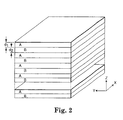
- Adjacent pairs of layers preferably have a total optical thickness that is 1/2 of the wavelength of the light desired to be reflected. as shown in Figure 2.
- the individual layers of a multilayer polymeric film have an optical thickness that is 1/4 of the wavelength of the light desired to be reflected, although other ratios of the optical thicknesses within the layer pairs may be chosen for other reasons.
- optical thickness is defined as the refractive index of a material multiplied by the actual thickness of the material. and that unless stated otherwise, all actual thicknesses discussed herein are measured after any orientation or other processing.
- the film will reflect light of different wavelengths.
- An important feature of the present invention is the selection of layers having desired optical thicknesses (by selecting the actual layer thicknesses and materials) sufficient to reflect light in the near infrared portion of the spectrum.
- pairs of layers will reflect a predictable band width of light, as described below, individual layer pairs may be designed and made to reflect a given band width of light. Thus, if a large number of properly selected layer pairs are combined, superior reflectance of a desired portion of the near infrared spectrum can be achieved.
- the bandwidth of light desired to be blocked, i.e., not transmitted, at a zero degree observation angle in accordance with an optical body of the present invention is from approximately 700 to 1200 nm.
- the layer pairs preferably have optical thicknesses ranging from 350 to 600 nm (1/2 the wavelength of the light desired to be reflected) in order to reflect the near infrared light.
- the multilayer film would have individual layers each having an optical thickness ranging from 175 to 300 nm (1/4 the wavelength of the light desired to be reflected), in order to reflect the near infrared light.
- the first layer material has a refractive index of 1 66 (as does biaxially oriented PET), and the second layer material has a refractive index of 1 52 (as does the biaxially oriented thermoplastic polyester commercially available from Eastman Chemical Co., Knoxville, TN, under the trade designation "Ecdel”)
- the actual thicknesses of the first material layers would range from approximately 105 to 180 nm
- the actual thicknesses of the second layers would range from approximately 115 to 197 nm.
- the optical properties of multilayer films such as this are discussed in detail below.
- the various layers in the film preferably have different thicknesses. This is commonly referred to as the layer thickness gradient.
- a layer thickness gradient is selected to achieve the desired band width of reflection.
- One common layer thickness gradient is a linear one, in which the thickness of the thickest layer pairs is a certain percent thicker than the thickness of the thinnest layer pairs.
- a 1.055:1 layer thickness gradient means that the thickest layer pair (adjacent to one major surface) is 5.5% thicker than the thinnest layer pair (adjacent to the opposite surface of the film).
- the layer thickness could decrease, then increase, then decrease again from one major surface of the film to the other.
- Suitable polymeric materials for use in the optical films of the present invention may be amorphous, semicrystalline, or crystalline polymeric materials.
- the films consist of at least two distinguishable polymers having different indices of refraction. The number is not limited, and three or more materials may be advantageously used in applications wherein it is desirable to eliminate higher order harmonics that would otherwise reflect light in the visible region of the spectrum and give a film with a colored appearance. For simplicity, the films will be described further considering an optical stack made from only two materials.
- the birefringence may be developed between two orthogonal directions in the plane of the film, between one or more in-plane directions and the direction perpendicular to the film plane, or a combination of these.
- the first polymer should be capable of maintaining birefringence after stretching, so that the desired optical properties are imparted to the finished film.
- the other required polymer referred to as the "second polymer” should be chosen so that in the finished film, its refractive index, in at least one direction, differs significantly from the index of refraction of the first polymer in the same direction. Because polymeric materials are typically dispersive, that is, the refractive indices vary with wavelength, these conditions must be considered in terms of a particular spectral bandwidth of interest.
- the difference in the index of refraction of the first and second polymers in one film-plane direction is advantageous for the difference in the index of refraction of the first and second polymers in one film-plane direction to differ significantly in the finished film, while the difference in the orthogonal film-plane index is minimized.
- the first polymer has a large refractive index when isotropic, and is positively birefringent (that is, its refractive index increases in the direction of stretching)
- the second polymer will be chosen to have a matching refractive index, after processing, in the planar direction orthogonal to the stretching direction, and a refractive index in the direction of stretching which is as low as possible.
- the second polymer will be chosen to have a matching refractive index, after processing, in the planar direction orthogonal to the stretching direction, and a refractive index in the direction of stretching which is as high as possible.
- the second polymer may be chosen so that, after processing, its refractive index will match that of the first polymer in either the stretching direction or the planar direction orthogonal to stretching. Further, the second polymer will be chosen such that the difference in index of refraction in the remaining planar direction is maximized, regardless of whether this is best accomplished by a very low or very high index of refraction in that direction.
- One means of achieving this combination of planar index matching in one direction and mismatching in the orthogonal direction is to select a first polymer which develops significant birefringence when stretched, and a second polymer which develops little or no birefringence when stretched, and to stretch the resulting film in only one planar direction.
- the second polymer may be selected from among those which develop birefringence in the sense opposite to that of the first polymer (negative - positive or positive - negative).
- Another alternative method is to select both first and second polymers which are capable of developing birefringence when stretched, but to stretch in two orthogonal planar directions, selecting process conditions, such as temperatures, stretch rates, post-stretch relaxation, and the like, which result in development of unequal levels of orientation in the two stretching directions for the first polymer, and levels of orientation for the second polymer such that one in-plane index is approximately matched to that of the first polymer, and the orthogonal in-plane index is significantly mismatched to that of the first polymer.
- process conditions such as temperatures, stretch rates, post-stretch relaxation, and the like, which result in development of unequal levels of orientation in the two stretching directions for the first polymer, and levels of orientation for the second polymer such that one in-plane index is approximately matched to that of the first polymer, and the orthogonal in-plane index is significantly mismatched to that of the first polymer.
- conditions may be chosen such that the first polymer has a biaxially oriented character in the finished film, while
- a reflective, or mirror, film Different considerations apply to a reflective, or mirror, film. Provided that the film is not meant to have some polarizing properties as well, refractive index criteria apply equally to any direction in the film plane, so it is typical for the indices for any given layer in orthogonal in-plane directions to be equal or nearly so. It is advantageous, however, for the film-plane indices of the first polymer to differ as greatly as possible from the film-plane indices of the second polymer For this reason, if the first polymer has a high index of refraction when isotropic, it is advantageous that it also be positively birefringent. Likewise, if the first polymer has a low index of refraction when isotropic, it is advantageous that it also be negatively birefringent.
- the second polymer advantageously develops little or no birefringence when stretched, or develops birefringence of the opposite sense (positive - negative or negative - positive), such that its film-plane refractive indices differ as much as possible from those of the first polymer in the finished film.
- Colored films can be regarded as special cases of mirror and polarizing films. Thus, the same criteria outlined above apply.
- the perceived color is a result of reflection or polarization over one or more specific bandwidths of the spectrum.
- the bandwidths over which a multilayer film of the current invention is effective will be determined primarily by the distribution of layer thicknesses employed in the optical stack(s), but consideration must also be given to the wavelength dependence, or dispersion, of the refractive indices of the first and second polymers It will be understood that the same rules apply to the infrared and ultraviolet wavelengths as to the visible colors.
- Absorbance is another consideration. For most applications, it is advantageous for neither the first polymer nor the second polymer to have any absorbance bands within the bandwidth of interest for the film in question. Thus, all incident light within the bandwidth is either reflected or transmitted. However, for some applications, it may be useful for one or both of the first and second polymer to absorb specific wavelengths, either totally or in part.
- Polyethylene 2,6-naphthalate is frequently chosen as a first polymer for films of the present invention. It has a large positive stress optical coefficient, retains birefringence effectively after stretching, and has little or no absorbance within the visible range. It also has a large index of refraction in the isotropic state. Its refractive index for polarized incident light of 550 nm wavelength increases when the plane of polarization is parallel to the stretch direction from about 1.64 to as high as about 1.9. Its birefringence can be increased by increasing its molecular orientation which, in turn, may be increased by stretching to greater stretch ratios with other stretching conditions held fixed.
- polystyrene dicarboxylic polyesters are also suitable as first polymers
- Polybutylene 2,6-Naphthalate (PBN) is an example. These polymers may be homopolymers or copolymers, provided that the use of comonomers does not substantially impair the stress optical coefficient or retention of birefringence after stretching.
- PEN herein will be understood to include copolymers of PEN meeting these restrictions. In practice, these restrictions imposes an upper limit on the comonomer content, the exact value of which will vary with the choice of comonomer(s) employed. Some compromise in these properties may be accepted, however, if comonomer incorporation results in improvement of other properties. Such properties include but are not limited to improved interlayer adhesion, lower melting point (resulting in lower extrusion temperature), better rheological matching to other polymers in the film, and advantageous shifts in the process window for stretching due to change in the glass transition temperature.
- Suitable comonomers for use in PEN, PBN or the like may be of the diol or dicarboxylic acid or ester type.
- Dicarboxylic acid comonomers include but are not limited to terephthalic acid, isophthalic acid, phthalic acid, all isomeric naphthalenedicarboxylic acids (2,6-, 1,2-, 1,3-, 1,4-, 1,5-, 1,6-, 1,7-, 1,8-, 2,3-, 2,4-, 2,5-, 2,7-, and 2,8-), bibenzoic acids such as 4,4'-biphenyl dicarboxylic acid and its isomers, trans-4,4'-stilbene dicarboxylic acid and its isomers, 4,4'-diphenyl ether dicarboxylic acid and its isomers, 4,4'-diphenylsulfone dicarboxylic acid and its isomers, 4,4'-benzophenone dicarboxylic acid and its isomers
- Suitable diol comonomers include but are not limited to linear or branched alkane diols or glycols (such as ethylene glycol, propanediols such as trimethylene glycol, butanediols such as tetramethylene glycol, pentanediols such as neopentyl glycol, hexanediols, 2,2,4-trimethyl-1,3-pentanediol and higher diols), ether glycols (such as diethylene glycol, triethylene glycol, and polyethylene glycol), chain-ester diols such as 3-hydroxy-2,2-dimethylpropyl-3-hydroxy-2,2-dimethyl propanoate, cycloalkane glycols such as 1,4-cyclohexanedimethanol and its isomers and 1,4-cyclohexanediol and its isomers, bi- or multicyclic diols (such as the various isomeric
- Tri- or polyfunctional comonomers which can serve to impart a branched structure to the polyester molecules, can also be used. They may be of either the carboxylic acid, ester, hydroxy or ether types. Examples include, but are not limited to, trimellitic acid and its esters, trimethylol propane, and pentaerythritol.
- comonomers are monomers of mixed functionality, including hydroxycarboxylic acids such as parahydroxybenzoic acid and 6-hydroxy-2-naphthalenecarboxylic acid, and their isomers, and tri- or polyfunctional comonomers of mixed functionality such as 5-hydroxyisophthalic acid and the like.
- PET Polyethylene terephthalate
- naphthalene dicarboxylic polyester such as PEN or PBN
- PEN naphthalene dicarboxylic copolyester
- This can be accomplished by choosing comonomers and their concentrations in the copolymer such that crystallizability of the coPEN is eliminated or greatly reduced.
- One typical formulation employs as the dicarboxylic acid or ester components dimethyl naphthalate at from about 20 mole percent to about 80 mole percent and dimethyl terephthalate or dimethyl isophthalate at from about 20 mole percent to about 80 mole percent, and employs ethylene glycol as diol component.
- dicarboxylic acids may be used instead of the esters.
- the number of comonomers which can be employed in the formulation of a coPEN second polymer is not limited. Suitable comonomers for a coPEN second polymer include but are not limited to all of the comonomers listed above as suitable PEN comonomers, including the acid, ester, hydroxy, ether, tri- or polyfunctional, and mixed functionality types.
- polycarbonates having a glass transition temperature compatible with that of PEN and having a refractive index similar to the isotropic refractive index of PEN are also useful as second polymers.
- Polyesters, copolyesters, polycarbonates, and copolycarbonates may also be fed together to an extruder and transesterified into new suitable copolymeric second polymers.
- the second polymer be a copolyester or copolycarbonate.
- Vinyl polymers and copolymers made from monomers such as vinyl naphthalenes, styrenes, ethylene, maleic anhydride, acrylates, acetates, and methacrylates may be employed.
- Condensation polymers other than polyesters and polycarbonates may also be used. Examples include: polysulfones, polyamides, polyurethanes, polyamic acids, and polyimides.
- Naphthalene groups and halogens such as chlorine, bromine and iodine are useful for increasing the refractive index of the second polymer to a desired level. Acrylate groups and fluorine are particularly useful in decreasing refractive index when this is desired.
- Suitable second polymer materials include but are not limited to polyethylene naphthalate (PEN) and isomers thereof (such as 2.6-, 1,4-, 1.5-, 2.7-.
- PEN polyethylene naphthalate
- isomers thereof such as 2.6-, 1,4-, 1.5-, 2.7-.
- polyalkylene terephthalates such as polyethylene terephthalate, polybutylene terephthalate, and poly-1,4-cyclohexanedimethylene terephthalate
- other polyesters polycarbonates, polyarylates, polyamides (such as nylon 6, nylon 11, nylon 12, nylon 4/6, nylon 6/6, nylon 6/9, nylon 6/10, nylon 6/12, and nylon 6/T), polyimides (including thermoplastic polyimides and polyacrylic imides), polyamide-imides, polyether-amides, polyetherimides, polyaryl ethers (such as polyphenylene ether and the ring-substituted polyphenylene oxides), polyarylether ketones such as polyetheretherketone (“PEEK”), aliphatic polyketones (such as copolymers and terpolymers of ethylene and/or propylene with carbon dioxide), polyphenylene sulfide, polysulfones (including polyethersulfones and poly
- copolymers such as the copolymers of PEN discussed above as well as any other non- naphthalene group -containing copolyesters which may be formulated from the above lists of suitable polyester comonomers for PEN
- copolyesters based on PET and comonomers from said lists above are especially suitable.
- first or second polymers may consist of miscible or immiscible blends of two or more of the above-described polymers or copolymers (such as blends of sPS and atactic polystyrene, or of PEN and sPS).
- syndiotactic vinyl aromatic polymers such as syndiotactic polystyrene.
- Syndiotactic vinyl aromatic polymers useful in the current invention include poly(styrene), poly(alkyl styrene)s, poly (aryl styrene)s, poly(styrene halide)s, poly(alkoxy styrene)s, poly(vinyl ester benzoate), poly(vinyl naphthalene), poly(vinylstyrene), and poly(acenaphthalene), as well as the hydrogenated polymers and mixtures or copolymers containing these structural units.
- poly(alkyl styrene)s include the isomers of the following: poly(methyl styrene), poly(ethyl styrene), poly(propyl styrene), and poly(butyl styrene)
- poly(aryl styrene)s include the isomers of poly(phenyl styrene)
- examples include the isomers of the following: poly(chlorostyrene), poly(bromostyrene), and poly(fluorostyrene).
- poly(alkoxy styrene)s include the isomers of the following: poly(methoxy styrene) and poly(ethoxy styrene).
- particularly preferable styrene group polymers are: polystyrene, poly(p-methyl styrene), poly(m-methyl styrene), poly(p-tertiary butyl styrene), poly(p-chlorostyrene), poly(m-chloro styrene), poly(p-fluoro styrene), and copolymers of styrene and p-methyl styrene.
- comonomers may be used to make syndiotactic vinyl aromatic group copolymers.
- suitable comonomers include olefin monomers (such as ethylene, propylene, butenes, pentenes, hexenes, octenes or decenes), diene monomers (such as butadiene and isoprene), and polar vinyl monomers (such as cyclic diene monomers, methyl methacrylate, maleic acid anhydride, or acrylonitrile).
- syndiotactic vinyl aromatic polymers and copolymers referred to in this invention generally have syndiotacticity of higher than 75% or more, as determined by carbon-13 nuclear magnetic resonance.
- the degree of syndiotacticity is higher than 85% racemic diad, or higher than 30%, or more preferably, higher than 50%, racemic pentad.
- the weight average molecular weight is greater than 10,000 and less than 1,000,000, and more preferably, greater than 50,000 and less than 800,000.
- syndiotactic vinyl aromatic polymers and copolymers may also be used in the form of polymer blends with, for instance, vinyl aromatic group polymers with atactic structures, vinyl aromatic group polymers with isotactic structures, and any other polymers that are miscible with the vinyl aromatic polymers.
- vinyl aromatic group polymers with atactic structures vinyl aromatic group polymers with isotactic structures
- any other polymers that are miscible with the vinyl aromatic polymers for example, polyphenylene ethers show good miscibility with many of the previous described vinyl aromatic group polymers.
- PEN/coPEN When a polarizing film is made using a process with predominantly uniaxial stretching, particularly preferred combinations of polymers for optical layers include PEN/coPEN. PET/coPET, PEN/sPS, PET/sPS, PEN/Eastar,TM and PET/Eastar,TM where "coPEN” refers to a copolymer or blend based upon naphthalene dicarboxylic acid (as described above) and EastarTM is a polyester or copolyester (believed to comprise cyclohexanedimethylene diol units and terephthalate units) commercially available from Eastman Chemical Co.
- coPEN refers to a copolymer or blend based upon naphthalene dicarboxylic acid (as described above) and EastarTM is a polyester or copolyester (believed to comprise cyclohexanedimethylene diol units and terephthalate units) commercially available from Eastman Chemical Co.
- PEN.coPEN PEN/PET
- PEN/PBT polybutylene terephthalate
- PET polybutylene terephthalate
- PET polybutylene terephthalate
- PET copolymer of PET employing a second glycol (usually cyclohexanedimethanol)
- PETcoPBT refers to a copolyester of terephthalic acid or an ester thereof with a mixture of ethylene glycol and 1,4-butanediol.
- Particularly preferred combinations of polymers for optical layers in the case of mirrors or colored films include PEN/PMMA, PET/PMMA, PEN/"Ecdel", PET/"Ecdel", PEN/sPS, PET/sPS, PEN/coPET, PEN/PETG, and PEN/a fluoropolymer commercially available from Minnesota Mining and Manufacturing Company (3M), St. Paul, MN under the trade designation "THV", where "PMMA” refers to polymethyl methacrylate, "coPET” refers to a copolymer or blend based upon terephthalic acid (as described above), and "PETG” refers to a copolymer of PET employing a second glycol (usually cyclohexanedimethanol).
- the in-plane refractive indices might be 1.76 for biaxially oriented PEN, while the film plane-normal refractive index might fall to 1.49.
- PMMA is used as the second polymer in the multilayer construction, its refractive index at the same wavelength, in all three directions, might be 1.495.
- PET/"Ecdel Another example is the PET/"Ecdel” system, in which the analogous indices might be 1 66 and 1.51 for PET, while the isotropic index of "Ecdel” might be 1.52.
- the crucial property is that the normal-to-plane index for one material must be closer to the in-plane indices of the other material than to its own in-plane indices.
- the multilaver optical films of the current invention may consist of more than two distinguishable polymers
- a third or subsequent polymer might be fruitfully employed as an adhesion-promoting layer between the first polymer and the second polymer within an optical stack, as an additional component in a stack for optical purposes, as a protective boundary layer between optical stacks, as a skin layer, as a functional coating, or for any other purpose.
- the composition of a third or subsequent polymer, if any, is not limited.
- Preferred multicomponent films include those described in U.S Serial No. 09/006,118 filed on 13.1.98, now published as WO99/36810A1, entitled "Multicomponent Optical Body".
- the reflectance characteristics of multilayer films are determined by several factors, the most important of which for purposes of this discussion are the indices of refraction for each layer of the film stack.
- reflectivity depends upon the relationship between the indices of refraction of each material in the x, y, and z directions (n x , n y , n z ).
- Different relationships between the three indices lead to three general categories of materials: isotropic, uniaxially birefringent, and biaxially birefringent. The latter two are important to the optical performance of the present invention.
- n x and n y In a uniaxially birefringent material, two indices (typically along the x and y axes, or n x and n y ) are equal, and different from the third index (typically along the z axis, or n z ).
- the x and y axes are defined as the in-plane axes, in that they represent the plane of a given layer within the multilayer film, and the respective indices n x and n y are referred to as the in-plane indices.
- One method of creating a uniaxially birefringent system is to biaxially orient (stretch along two axes) a multilayer polymeric film. Biaxial orientation of the multilayer film results in differences between refractive indices of adjoining layers for planes parallel to both axes, resulting in the reflection of light in both planes of polarization.
- a uniaxially birefringent material can have either positive or negative uniaxial birefringence. Positive uniaxial birefringence occurs when the index of refraction in the z direction (n z ) is greater than the in-plane indices (n x and n y ).
- an infrared mirror can be made that is transparent in the visible region of the spectrum, even at high angles of incidence.
- the reflective bandedge may be positioned so that even at grazing angles of incidence, the reflectance band does not shift past the colored portion of the visible spectrum, thereby maintaining the same visible color at grazing angles as at normal angle of incidence. This same effect may be achieved by positioning two uniaxially oriented films (discussed below) with their respective orientation axes at 90° to each other.
- a biaxially birefringent system can be made by uniaxially orienting (stretching along one axis) the multilayer polymeric film, such as along the x direction in Figure 2.
- a biaxially birefringent multilayer film can be designed to provide high reflectivity for light with its plane of polarization parallel to one axis, for all angles of incidence, and simultaneously have low reflectivity (high transmissivity) for light with its plane of polarization parallel to the other axis at all angles of incidence.
- the biaxially birefringent system acts as a polarizer, reflecting light of one polarization and transmitting light of the other polarization.
- a polarizing film is one that receives incident light of random polarity (light vibrating in planes at random angles), and allows incident light rays of one polarity (vibrating in one plane) to pass through the film, while reflecting incident light rays of the other polarity (vibrating in a plane perpendicular to the first plane).
- an infrared polarizer can be made that is transparent in the visible region of the spectrum, even at high angles of incidence.
- the reflective bandedge may be positioned so that even at grazing angles of incidence, the reflectance band does not shift past the colored portion of the visible spectrum, thereby maintaining the same visible color at grazing angles as at normal angle of incidence.
- Two crossed sheets of biaxially birefringent film would yield a highly efficient mirror, and the films would perform similar to a single uniaxially birefringent film.
- PEN/PET An example of a system that produces a good polarizer from biaxial orientation is PEN/PET.
- the indices of refraction can be adjusted over a range of values.
- Copolymers of PEN and PET may also be used. For example, a copolymer comprising approximately 10% PEN subunits and 90% PET subunits by weight may replace the PET homopolymer in the construction.
- n 1x 1 67
- n 1x 1 62
- n 1z 1 52, at 632.8 nm.
- refractive indices in the x direction a large difference (for strong reflection) in the y direction
- a small difference in the z direction This small z index difference minimizes unwanted color leaks at shallow observation angles.
- the film formed by biaxial orientation is strong in all planar directions, while uniaxially oriented polarizer is prone to splitting. Depending on the application, either approach has merit.
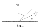
- the infrared reflecting multilayer film of the present invention may be designed so that the reflecting band is positioned within the infrared region at such a wavelength that it does not reflect red light at angles less than the angle of use. If the reflection band is not positioned sufficiently far into the infrared, then the film will reflect red at angles greater than the angle of use. Because cyan is by definition the subtraction of red light from white light, the film appears cyan in transmission. The amount of red light reflected, and thus the degree to which the film appears cyan, depends on the observation angle and the reflected band width.
- the observation angle alpha is measured between the photoreceptor (typically a human eye) and the observation axis perpendicular to the plane of the film.
- the observation angle is approximately zero degrees, very little visible light of any color is reflected by the multilayer film, and the film appears clear against a diffuse white background (or black against a black background).
- the observation angle exceeds a predetermined shift angle and the short wavelength bandedge has not been positioned properly within the infrared, a substantial portion of the red light is reflected by the multilayer film, and the film appears cyan against a diffuse white background (or red against a black background).
- the observation angle increases toward 90 degrees, more red light is reflected by the multilayer film, and the cyan appears to be even deeper.
- the shift into the red region of the spectrum may be acceptable, for example, if the film is already cyan in appearance at normal angles, for example, because of the incorporation of an absorbing dye, then the short wavelength bandedge may shift beyond the visible into the red region so long as it does not move beyond the absorption bandedge of the dye to cause a change in the perceived color with angle.
- the reflectance peak is very narrow.
- the breadth or band width of the transmission minimum is about 42 nm.
- the band width is 77 nm.
- the reflective band of the film of the present invention should be designed to cover from about 850 nm to about 1200 nm.
- the band width for a given pair of materials may be estimated from Equation 3, multiplying by the layer thickness ratio.
- the center of the reflectance band is calculated from Equations I or 2 so that it is positioned approximately one half band width from the desired location of the lower bandedge.
- the compounded effects result in a greater blue shift of the spectrum compared to film stacks composed entirely of isotropic materials.
- the actual blue shift will be determined by the thickness weighted average change in ⁇ with angle of incidence for all material layers in the unit cell.
- the blue shift can be enhanced or lessened by adjusting the relative thickness of the birefringent layer(s) to the isotropic layer(s) in the unit cell. This will result in f-ratio changes that must first be considered in the product design.
- the maximum blue shift in mirrors is attained by using negatively uniaxially birefringent materials in all layers of the stack.
- the minimum blue shift is attained by using only uniaxially positive birefringent materials in the optical stack.
- biaxially birefringent materials are used, but for the simple case of light incident along one of the major axes of a birefringent thin film polarizer, the analysis is the same for both uniaxial and biaxial films. For directions between the major axes of a polarizer, the effect is still observable but the analysis is more complex.
- the in-plane/z-axis index differential of the PEN layers is about 1.75 - 1 50. This index differential is less for PET-based films (i e., about 1.66 - 1.50)
- the effect is even more pronounced because the difference in the PEN in-plane index compared to the PEN z-axis index is much greater (about 1.85 - 1.50), resulting in an even greater blue shift for p-polarized light than that observed in isotropic multilayer film stacks. If only uniaxially positive birefringent materials were used in the stack, the blue shift would be diminished compared to isotropic optical films.
- the angular dependence of the red light reflectance is illustrated in Figures 3 and 4.
- the percent of transmitted light is plotted along the vertical axis, and the wavelengths of light are plotted along the horizontal axis. Note that because the percentage of light transmitted is simply 1 minus the percentage of reflected light (absorption is negligible), information about light transmission also provides information about light reflection.
- the spectra provided in Figures 3 and 4 are taken from a computerized optical modeling system, and actual performance typically corresponds relatively closely with predicted performance. Surface reflections contribute to a decreased transmission in both the computer modeled and measured spectra. In examples for which actual samples were tested, a spectrometer available from the Perkin Elmer Corporation of Norwalk, Connecticut under the designation Lambda 19 was used to measure optical transmission of light at the angles indicated.
- the spectra for this ideal film at a zero degree observation angle and a 60 degree observation angle are plotted in Figures 3 and 4, respectively.
- the low wavelength bandedge for both the s- and p-polarized light shift together from about 750 nm to about 600 nm and transmission is minimized in the desired range of the spectrum, so that to the eye, a very sharp color shift is achieved.
- the low wavelength bandedge for p-polarized light viewed at a 60 degree observation angle shifts by about 100 nm, while that for s-polarized light shifts by about 150 nm.
- This construction does not exhibit an abrupt change from clear to cyan because the s- and p-polarized light do not shift together with change in angle.
- the value for the shift for p-polarized light for a construction with an isotropic film would likely be between the shift achieved using a birefringent film and that achieved using an inorganic isotropic film, depending on the index of refraction of the specific materials used.
- a dielectric reflector is composed of layer groups that have two or more layers of alternating high and low index of refraction. Each group has a halfwave optical thickness that determines the wavelength of the reflection band. Typically, many sets of halfwaves are used to build a stack that has reflective power over a range of wavelengths. Most stack designs have sharp reflectivity decreases at higher and lower wavelengths, know as bandedges.
- the edge above the halfwave position is the high wavelength bandedge, l BEhi , and the one below is the low wavelength bandedge, l BElo . These are illustrated in Figure 8.
- the center, edges, and width of a reflection band change with incident angle.
- the reflecting band can be exactly calculated by using a characteristic matrix method.
- the characteristic matrix relates the electric field at one interface to that at the next. It has terms for each interface and each layer thickness. By using effective indicies for interface and phase terms, both anisotropic and isotropic materials can be evaluated.
- the characteristic matrix for the halfwave is the product of the matrix for each layer of the halfwave.
- the characteristic matrix for each layer is given by Equation 6 where r i and t i are the Fresnel coefficients for the interface reflection of the i th interface, and b i is the phase thickness of the i th layer.
- the characteristic matrix of the entire stack is the product of the matrix for each layer. Other useful results, such as the total transmission and reflection of the stack, can be derived from the characteristic matrix.
- the incident material has an index of n O and an angle of q O .
- the wavelength edge of the high reflectance region can be determined by evaluating the M 11 and M 22 elements of the characteristic matrix of the stack at different wavelengths. At wavelengths where Equation 10 is satisfied, the transmission exponentially decreases as more halfwaves are added to the stack Equation 10: M 11 + M 22 2 ⁇ 1
- the edge of a reflection band can be determined from the characteristic matrix for each halfwave.
- the characteristic matrix for the stack can be derived by matrix multiplication of the component layers to generate the total matrix at any wavelength.
- a bandedge is defined by wavelengths where Equation 11 is satisfied. This can be either the first order reflection band or higher order reflections. For each band, there are two solutions. There are additional solutions at shorter wavelengths where higher order reflections can be found.
- a preferred method of making the multilayer film of the present invention is illustrated schematically in Figure 7, and is described in even greater detail in U S Serial No. 09/006,288 entitled “Process for Making Multilayer Optical Films” filed on 13.01.98, published as WO 99/36248A2.
- materials 100 and 102 selected to have suitably different optical properties are heated above their melting and/or glass transition temperatures and fed into a multilayer feedblock 104, with or without a layer multiplier 106.
- the layer multiplier 106 splits the multilayer how stream, and then redirects and "stacks" one stream atop the second to multiply the number of layers extruded.
- An asymmetric multiplier when used with extrusion equipment that introduces layer thickness deviations throughout the stack, may broaden the distribution of layer thicknesses so as to enable the multilayer film to have layer pairs corresponding to a desired portion of the visible spectrum of light, and provide a desired layer thickness gradient.
- Skin layers may also be introduced by providing material 108 for skin layers to a skin layer feedblock 110.
- the multilayer feedblock feeds a film extrusion die 112.
- Feedblocks useful in the manufacture of the present invention are described in, for example, U.S. Patent Nos. 3,773,882 and 3,884,606, and U.S. Serial No. 09/006,288 entitled "Process for Making Multilayer Optical Films" filed on 13.11.98, now WO99/36248A2.
- the extrusion temperature may be approximately 295° C, and the feed rate approximately 10-150 kg/hour for each material. It is desirable in most cases to have skin layers 111 flowing on the upper and lower surfaces of the film as it goes through feedblock 110 and before it goes through die 112.
- These layers 111 serve to dissipate the large stress gradient found near the wall, leading to smoother extrusion of the optical layers.
- Typical extrusion rates for each skin layer 111 would be 2-50 kg/hr (1-40% of the total throughput).
- the skin material may be the same as one of the optical layers, or a third polymer.
- the melt After exiting die 112, the melt is cooled on a casting wheel 116, which rotates past pinning wire 114. Pinning wire 114 pins the extrudate to casting wheel 116.
- the film then travels through lengthwise orientation pull rolls 118, tenter oven 120, heat set portion 122 of tenter oven 120 and then to wind up roll 124.
- the film is oriented by stretching at ratios determined with reference to the desired optical and mechanical properties.
- Stretch ratios of approximately 3-4 to 1 are preferred, although ratios as small as 2 to 1 and as large as 6 to 1 may also be appropriate to a given film. Stretch temperatures will depend on the type of birefringent polymer used, but 2° to 33° C (5° to 60° F) above its glass transition temperature would generally be an appropriate range.
- the film is typically heat set in the last two zones of tenter oven 120 to impart the maximum crystallinity in the film and reduce its shrinkage. Employing a heat set temperature as high as possible without causing film breakage in the tenter oven 120 reduces the shrinkage during a heated embossing step. A reduction in the width of the tenter rails by about 1-4% also serves to reduce film shrinkage. If the film is not heat set, heat shrink properties are maximized, which may be desirable in some security packaging applications.
- a suitable multilayer optical body may also be prepared using techniques such as spin coating, e.g ., as described, for example, in Boese et al., J. Polym. Sci.: Part B, 30:1321(1992) for birefringent polyimides, and vacuum deposition, e.g. , as described by Zang et. al., Appl. Phys Letters, 59 ⁇ 823 (1991) for crystalline organic compounds; the latter technique is particularly useful for certain combinations of crystalline organic compounds and inorganic materials.
- Orientation of the extruded film may be done by stretching individual sheets of the material in heated air.
- stretching may be accomplished on a continuous basis in a standard length orienter, i.e., lengthwise orientation pull rolls 118, tenter oven 120, or both.
- economies of scale and line speeds of standard polymer film production may be achieved thereby achieving manufacturing costs that are substantially lower than costs associated with commercially available absorptive polarizers.
- other layers and features of the inventive film may include slip agents, low adhesion backsize materials, conductive coatings, antistatic, antireflective or antifogging coatings or films, barrier layers, flame retardants, UV stabilizers or protective layers, abrasion resistant materials, optical coatings, or substrates to improve the mechanical integrity or strength of the film.
- Non-continuous layers may also be incorporated into the film to prevent tampering.
- inorganic or organic adjuvants such as an antioxidant, extrusion aid, heat stabilizer, ultraviolet ray absorber, nucleator, surface projection forming agent, and the like in normal quantities so long as the addition does not substantially interfere with the performance of the present invention.
- Lamination of two or more sheets together may be advantageous, to improve reflectivity or to broaden the bandwidth, or to form a mirror from two polarizers.
- Amorphous copolyesters are useful as laminating materials.
- Exemplary amorphous copolyesters include those commercially available from Goodyear Tire and Rubber Co. of Akron, Ohio, under the trade designations "VITEL Brand 3000” and “VITEL Brand 3300".
- the choice of laminating material is broad, with adhesion to the sheets 10, optical clarity and exclusion of air being the primary guiding principles.
- a characteristic of dielectric multilayer thin interference films is that the reflected wavelength shifts to shorter wavelengths at higher angles of view.
- the thicknesses of the individual layer pairs are increased such that their resonant first order wavelengths occur at a higher wavelength than would normally be desired. This increase follows equation 11.
- the optical body of the present invention further include a wavelength gap filler component in conjunction with the film described above.
- the gap filler component functions to either absorb or reflect the infrared wavelengths that are not reflected by the film at normal angles because of the need to shift the reflective band of the film to higher wavelengths in order to minimize perceived color changes at non-normal incidence.
- the component may not function at non-normal angles because the reflective band shifts to lower wavelengths, preferably coinciding with the wavelength region of the absorption or reflection of the gap filler component.
- Suitable gap filler components include an infrared absorbing dye or pigment, an infrared absorbing glass, a trailing segment, a plurality of isotropic layers, or combinations thereof
- the gap filler component may be a part of the film, for example, as a trailing segment or a plurality of isotropic layers coextruded with the film layers or as a dye or pigment incorporated into one or more of the film layers.
- the gap filler component may be a discrete part of the optical body of the present invention, i.e., separate from the film, that is attached, for example, laminated thereto. Examples of this embodiment include a dye or pigment as a separate layer adhered to the film.
- gap filler as a part of the film and separate from the film is merely exemplary
- the gap filler component disclosed herein may be either be a part of the film or may be separate from the film depending on the characteristics of the component itself and the film with which it is being combined.
- the film and the gap filler components are preferably combined such that the film is placed on a surface nearest the sun as practical because it is more efficient to reflect solar energy than to absorb it.
- the sun's rays first encounter the film and then secondarily encounter the gap filler component
- the most preferable placement for the film is the exterior nearest the sun, the next preferably position is between the panes or plies.
- the film may be placed on the interior surface but this allows absorption of solar light by the glass before the light reaches the film and absorption of part of the light reflected from the film
- This embodiment may be preferable when considered from a UV protection standpoint, since it may be preferable to position the film away from the sun, allowing components which are less sensitive to UV to absorb this part of the light.
- suitable infrared absorbing dyes include cyanine dyes as described, for example, in U.S. Patent No. 4,973,572, as well as bridged cyanine dyes and trinuclear cyanine dyes as described, for example, in U.S. Patent No. 5,034,303, merocyanine dyes as described, for example, in U S. Patent No.
- carbocyanine dyes for example, 3,3'-diethyloxatricarbocyanine iodide, 1,1',3,3,3',3'-hexamethylindotricarbocyanine perchlorate, 1,1',3,3,3',3'-hexamethylindotricarbocyanine iodide, 3,3'-diethylthiatricarbocyanine iodide, 3,3'-diethylthiatricarbocyanine perchlorate, 1,1',3,3,3',3'-hexamethyl-4,4',5,5'-dibenzo-2,2'-indotricarbocyanine perchlorate, all of which are commercially available from Kodak, Rochester, NY), and phthalocyanine dyes as described, for example, in U.S.
- metal dithiolate dyes for example, nickel dithiolate dyes and, for example, bis[4-dimethylaminodithiobenzil] nickel, bis[dithiobenzil] nickel, bis[1,2-bis(n-butylthio)ethene
- polymethine dyes such as bis(chalcogenopyrylo)polymethine dyes as described, for example, in U S. Patent No. 4,948,777, bis(aminoaryl) polymethine dyes as described, for example, in U.S. Patent No. 4,950,639, indene-bridged polymethine dyes as described, for example, in U.S. Patent No. 5,019,480, and tetraaryl polymethine dyes; diphenylmethane dyes; triphenylmethane dyes; quinone dyes; azo dyes; ferrous complexes as described, for example, in U.S. Patent No.
- Patent No 5,035,977 squaraine dyes such as chromylium squaraine dyes, thiopyrylium squaraine dyes as described, for example, in U.S. Patent No. 5.019,549, and thiochromylium squaraine dyes, polyisothianaphthene dyes; indoaniline and azomethine dyes as described, for example, in U.S. Patent No 5,193,737, indoaniline methide dyes; tetraarylaminium radical cation dyes and metallized quinoline indoaniline dyes Squarylium dyes or squaraines are also described, for example, in U.S. Patent No. 4,942,141 and U.S. Patent No. 5,019,549.
- squaraine dyes such as chromylium squaraine dyes, thiopyrylium squaraine dyes as described, for example, in
- phthalocyanine dyes include, for example, those available from Zeneca Corporation, Blackley, Manchester, England under the trade designation "Projet Series” for example, “Projet 830NP”, “Projet 860 NP” and “Projet 900NP”
- metal complex dyes include those available from C.C. Scientific Products, Ft. Worth, TX 76120, for example, bis[4-dimethylaminodithiobenzil] nickel.
- Useful near infrared absorbing dyes include those from Epolin, Inc., Newark, NJ, for example, having the trade designations: Epolight III-57, Epolight III-117, Epolight V-79, Epolight V-138, Epolight V-129, Epolight V-99, Epolight V-130, Epolight V-149, Epolight IV-66, Epolight IV-62A, and Epolight III-189.
- Suitable infrared absorbing pigments include cyanines, metal oxides and squaraines.
- Suitable pigments include those described in U.S. Patent No. 5,215,838, such as metal phthalocyanines, for example, vanadyl phthalocyanine, chloroindium phthalocyanine. titanyl phthalocyanine, chloroaluminum phthalocyanine, copper phthalocyanine, magnesium phthalocyanine, and the like, squaraines, such as hydroxy squaraine, and the like; as well as mixtures thereof.
- Exemplary copper pthalocyanine pigments include the pigment commercially available from BASF under the trade designation "6912".
- Other exemplary infrared pigments include the metal oxide pigment commercially available from Heubach Langelsheim under the trade designation "Heucodor".
- Dyes or pigments useful in the present invention may be narrow-band absorbing, absorbing in the region of the spectrum not covered because of the position of the short wavelength bandedge of the optical body, for example, 700 to 850 nm, or may be broad band, absorbing over substantially all or all of the infrared region.
- the dye or pigment can be applied to either surface of the film, in a layer of glass or polymer, such as polycarbonate or acrylic, laminated to the film, or be present in at least one of the polymer layers of the film.
- the dye is preferably on the innermost surface of the film the toward the room interior and away from the sun) so that when the sun is a high angle, the film reflective band shifts to lower wavelengths. essentially coinciding with the wavelength region of the dye. This is preferred because reflecting solar energy away from the building is preferred to absorbing it.
- the amount of dye or pigment used in the optical body of the present invention varies depending on the type of dye or pigment and/or the end use application.
- the dye or pigment when applied to the surface of the film, the dye or pigment is present on the surface at a concentration and coating thickness suitable to accomplish the desired infrared absorption and visible appearance.
- the concentration ranges from about 0.05 to about 0.5 weight %, based on the total weight of the optical body.
- a pigment when a pigment is used, a small particle size typically is needed, for example, less than the wavelength of light.
- the dyes are non-polar solvent soluble, the dyes can be coated or mixed in with solid plastic pellets and extruded if the dyes can withstand the heat of mixing and extrusion.
- suitable infrared absorbing glasses include clear glass having a thickness generally ranging from about 3 to about 6 mm, such as architectural or automotive glass; blue glass, or green glass which selectively absorb in the near infrared, i.e., about 700 to 1800 nm.
- the film of the present invention is located on the surface of the glass closest to the sun so that the film can reflect away the 850-1250 nm wavelengths, allowing some of the infrared which is not reflected to be absorbed by the glass. If it is not practical to place the film on the exterior surface of a glass layer, for example, on the exterior of a window of a building, it may be useful to place the film between panes of glass, rather than on the surface closest to the interior, in the case of multiple pane windows, in order to minimize absorption.
- the exterior layer (closest to the sun) has minimal infrared absorbing properties so that the film is able to reflect light in the infrared region before this light reaches the interior infrared absorbing glass.
- the glass temperature would be lower and less heat would enter the room due to re-radiation of absorbed light.
- the glass and/or film would be cooler which would reduce cracking of the glass due to thermal stress, a common problem with heavily absorbing materials.
- Infrared absorbing glass is available commercially from companies including Pittsburgh Plate Glass (PPG), Guardian, Pilkington-Libbey Owens Ford, Toledo, OH.
- PPG Pittsburgh Plate Glass
- Guardian Guardian
- Pilkington-Libbey Owens Ford Toledo
- OH OH
- a sharp band edge is desired in optical interference films such as the infrared reflective films described herein.
- Sharp band edges can be obtained from proper design of the layer thickness gradient throughout the multilayer optical stack, as described in U.S. Serial No. 09/006,085 entitled “Optical Film with Sharpened Bandedge” filed by on 13.01.98, now WO 99/36809A1.
- a reflective film of the present invention can be designed to include a trailing segment to partially reflect infrared wavelengths in the gap region without producing strong color in the visible spectrum at non-normal angles.
- a trailing segment can be provided as a multilaver interference film have layer thicknesses and refractive indices such that the reflectance in the gap region is relatively weak, for example, 50% and which may decrease so that transfer from high reflectance to low reflectance of the multilaver film is gradual.
- a layer gradient may provide a sharp bandedge above, for example, the 50% reflectance point and a trailing segment could be provided by additional layers.
- the last 30 layers of a 200 layer stack could be of appropriate optical thickness that their first order reflection occurs in the range of about 800-850 nm. the intensity of which increase from about 90% reflection at 850 nm to about 25% at 800 nm.
- the other 170 layers could provide, for example, about 90% reflection from about 850-1150 nm.
- Achieving the trailing segment can be done in a number of ways, for example, by controlling the volumetric feed of the individual layers.
- the trailing segment may be extruded with the multilayer film of the present invention or laminated thereto.
- trailing segment provides a "softer" transition which may be more aesthetically acceptable and easier to control from a process standpoint.
- An isotropic multilayer film could also be used to cover at least a portion of the wavelength gap.
- the optical body of the present invention may comprise the combination of any film described herein and any gap filler component described herein, with the proviso that when a polymeric isotropic material is selected as the film, the gap filler component is not a polymeric isotropic material and when a polymeric isotropic material is selected as the gap filler component, the film is not selected to be a polymeric isotropic material.
- Isotropic layers lose p-pol reflection intensity at oblique angles. If a birefringent film is used as the multilayer film, for example, PEN/PMMA. isotropic layers can be used to cover at least a portion of the gap. Accordingly, at oblique angles, the z-index matched reflectance band would shift into the gap and the reflectance from the isotropic layers would shift to the visible but also decrease in p-pol intensity. S-pol would be masked or partially masked by the air/optical body surface which would increase its reflectance at oblique angles.
- Exemplary isotropic polymers include but are not limited to isotropic coPEN, PMMA, polycarbonates, styrene acrylonitriles, PETG, PCTG, styrenics, polyurethanes, polyolefins, and fluoropolymers.
- the isotropic film could be coextruded with the film of the present invention or laminated to this film.
- Gap filler components may be used in combination with the multilayer film of the present invention, for example, when each gap filler component only absorbs or reflects in a portion of the gap to be filled.
- shifting the bandedge and, thus, creating the gap also serves to create another, or second, gap in the infrared region at longer wavelengths off angle. Therefore, it may be preferable to also include a component which fills this second gap region off angle.
- the present invention also encompasses an optical body comprising a birefringent or isotropic dielectric multilayer film, as described above, in combination with a gap filler component which only fills the second gap in the infrared region at longer wavelengths off angle.
- Suitable gap filler components to fill this second gap include dyes, pigments, glasses, metals and multilayer films which absorb or reflect in the longer wavelengths of the infrared region, as described above.
- gap filler component (a) is situated such that light hits the multilayer film of the present invention before it hits the gap filler component so that, then when the sun is at normal incidence, the gap filler absorbs light in the region of the gap.
- the film will shift to some of the same wavelengths as the gap filler component and serve to reflect at least some of the light in the region of the gap.
- a multilayered infrared optical body in accordance with the present invention may be combined with a transparent conductor to provide a transparent multilayer optical body having broader reflectivity.
- the transparent conductor provides good far infrared reflection (above about 2500 nm) although its reflectivity in the near infrared region of the spectrum generally is not as good throughout the region of about 700 nm to about 2500 nm.
- the optical body of the present invention can be designed or "tuned" to provide the desired infrared reflection while still transmitting sufficient light to be transparent.
- the transparent conductors useful in the present invention are those that reflect light in the far infrared region of the spectrum, and more particularly include those effective in efficiently partitioning infrared light (above about 700 nm) from visible light (between about 380 nm and about 700 nm). In other words, the transparent conductor passes light in the wavelength region sensitive to the human eye while rejecting light in the infrared region. Because both high visible transmission and low near infrared transmission are desired, the reflective edge necessarily must be above about 700 nm, just out of the sensitivity of the human eye.
- Suitable transparent conductors are electrically conductive materials that reflect well in the far infrared spectrum and include metals, metal alloys, and semiconductive metal oxide materials.
- Preferred metals include silver, gold, copper, and aluminum. Other metals, such as nickel, sodium, chromium, tin, and titanium, may also be used, but they generally are not as effective in partitioning infrared light from visible light. Silver is particularly preferred since it can be applied in the form of a very thin film and optically has a relatively high transmittance over the entire visible light region while also possessing the ability to reflect light of longer wavelengths than visible light.
- Preferred semiconductive metal oxides include doped and undoped tin dioxide (SnO 2 ), zinc oxide (ZnO), and indium tin oxide (ITO) with the latter being particularly preferred.
- Preferred metal alloys include silver alloys, stainless steel, and inconel.
- Silver alloys especially those containing at least 30 wt. % silver, are particularly preferred for the same reasons that silver is preferred, but have the added advantage of improved durability, such as a silver alloy containing, in addition to silver, less than 50 wt. % gold and/or less than 20 wt. % copper.
- the transparent conductor may comprise a single metal layer or a plurality of layers, each of which may contain one or more metals, metal alloys, and metal oxides.
- Metals and metal alloys useful as transparent conductors in the present invention have electrical conductivities ranging between about 0.02 mhos/sq. to about 1.0 mhos/sq., preferably between about 0.05 mhos/sq. to about 1.0 mhos/sq., and may be applied in a thickness from about 10 nm to about 40 nm, preferably between about 12 nm to about 30 nm.
- Preferred semiconductive metal oxide layers have an electrical conductivity ranging between about 0.0001 mhos/sq.
- the transparent conductor is a metalized polymer or glass sheet laminated to the multilayered polymer film
- the metal or metal alloy coatings on the sheet preferably have a thickness from about 10 nm to about 40 nm, while metal oxide coatings on the sheet preferably have a thickness from about 20 nm to about 200 nm.
- thin metal transparent conductors such as silver
- their reflectivity in the near infrared region between about 700 nm and about 1200 nm is not as good as compared to the reflectivity that can be achieved in that region by the multilayered polymer films used in the present invention.
- the multilayered polymer films described above have high transmission of visible light and comparatively good reflection in the near infrared region with relatively low to poor reflectivity in the far infrared region.
- the multilayered polymer films are also generally capable of providing a sharper transition between visible and infrared light than the transparent conductors.
- the combination of the multilayered polymer film with the transparent conductor to form the transparent multilayer optical body of the present invention provides better reflectivity throughout the entire infrared region while still transmitting visible light.
- antireflective coatings which are well known to those of ordinary skill in the art, may be coated over the transparent conductor to increase the transmission of visible light. This includes, for example, an antireflective coating consisting of a metal, dielectric, metal stack with the individual layer thicknesses controlled to provide the desired visible transmission.
- antireflective coatings are not required by the present invention to obtain the desired transmission of light in the visible spectrum.
- the bandwidth of this reflectivity in the infrared region is also dependent upon color and/or the level of transmission desired in the visible range since overtones and third order effects, which occur for first orders above about 1150 nm, will undesirably increase reflection in the visible spectrum as is well known to those of ordinary skill in this art.
- One way to avoid significantly impacting deleteriously the transmission of visible light is to control the thicknesses of the individual layers in the multilayered polymer film as discussed above to limit the reflection band in the near infrared spectrum to a preselected range, such as between 700 nm and about 1150 nm where the solar spectrum is more intense than further out in the infrared spectra.
- the desired transmission in the visible spectrum will be maintained, and the combination of transparent conductor and multilayered polymer film will reflect the desired amount of light, with the multilayer film dominating the reflection in the near infrared from about 700 nm to about 1150 nm, and the transparent conductor dominating the reflection in the infrared spectrum above about 1150 nm.
- Other ways to achieve this result are also known in the art. See, for example, Alfred Thelen, “Multilayer Filters with Wide Transmittance Bands," J. Opt. Soc. Am. 53(11), 1963, p. 1266, and Philip Baumeister, “Multilayer Reflections With Suppressed Higher Order Reflection Peaks," Applied Optics 31(10), 1992, p 1568, and U.S.
- the transparent conductor may be applied to the multilayered polymer films by conventional coating techniques well-known to those of ordinary skill in this art, with the understanding that the resulting multilayered optical body is transparent
- coating techniques well-known to those of ordinary skill in this art, with the understanding that the resulting multilayered optical body is transparent
- Such known processes include pyrolysis, powder coating, vapor deposition, cathode sputtering, ion plating, and the like. Cathode sputtering and vapor deposition are often preferred in view of the uniformity of structure and thickness that can be obtained.
- the transparent conductor may be a separate metalized polymer or glass sheet that is laminated to the multilayered polymer film by means of a suitable adhesive, preferably a hot melt adhesive such as the VITEL 3300 adhesive from Shell Chemical Company, Akron, Ohio, or a pressure sensitive adhesive such as 90/10 IOA/AA and 95/5 IOA/acrylamide acrylic PSAs from Minnesota Mining and Manufacturing Company (3M), St. Paul, MN.
- a suitable adhesive preferably a hot melt adhesive such as the VITEL 3300 adhesive from Shell Chemical Company, Akron, Ohio
- a pressure sensitive adhesive such as 90/10 IOA/AA and 95/5 IOA/acrylamide acrylic PSAs from Minnesota Mining and Manufacturing Company (3M), St. Paul, MN.
- the thickness of the transparent conductor applied to the multilayered polymer films to form the transparent multilayer optical body of the present invention can be selected to provide the desired reflectivity.
- the thinner the metal layer the more light in the visible spectrum will be transmitted.
- the electrical conductivity of the metal layer decreases as its thickness decreases, the amount of light reflected in the far infrared spectrum also decreases as the thickness of the metal layer decreases.
- the transparent conductor can provide the desired balance between transmission of light in the visible spectrum and reflection of light in the far infrared spectrum.
- the thickness of the metal layer deposited on the multilayered polymer film can be monitored by measuring the metal layer's electrical conductivity.
- the optical body of the present invention generally has no perceived color change with a change in viewing angle or angle of incidence of impinging light, and is preferably uncolored, and has a modest shading coefficient.
- the shading coefficient is the amount of solar energy that enters a window as compared to that of a simple pane of clear glass, and can be measured as follows
- the measured sample transmission spectra is multiplied by the sensitivity function of the human eye integrated over the visible spectrum and is referred to as T lum .
- the measured sample reflection (R AM2 ) and transmission spectra (T AM2 ) are integrated over air mass 2 solar spectrum according to ASTM E903, "Standard Test For Solar Absorbance. Reflectance, and Transmittance of Materials Using Integrating Spheres.”
- the dominant wavelength is the apparent color of the sample that is calculated with CIE techniques using Illuminant C and the 10° observer according to ASTM E308, "Standard Test Method for Computing The Colors of Objects Using the CIE System.”
- the color purity is the saturation of the color, with 0% being white and 100% being a pure color.
- the optical body of the present invention preferably has a shading coefficient of less than 0.6.
- the optical body of the present invention have desirable optical properties in that they reflect and/or absorb the desired amount of light in the infrared region of the spectrum, and preferably transmitting sufficient light in the visible region of the spectrum to be transparent.
- the optical body of the present invention controls the amount of solar energy that passes through it preferably without significantly decreasing the intensity or changing the color of light sensed by the human eye at any angle.
- the optical body of the present invention aids in reducing required cooling in summer. Consequently, the optical body can be used by applying it directly to the surface of a glass or plastic substrate, such as an exterior window in a building or the windshield or window of an automobile, truck or aircraft. It is also suitable for laminated glass and plastic articles in which at least one transparent multilayer optical body is sandwiched between pairs of glass or plastic panes. Other uses would be apparent to those of ordinary skill in this art where protection is desired from infrared radiation while still obtaining substantial transparency to light in the visible region of the spectrum, such as, for example, applying the transparent multilayer optical body of the present invention to the window in a door to a refrigerated display case.
- the gap filler is next to the interior surface of the window and the multilayered polymer film faces the house or automobile interior.
- the outer surface of the multilayered polymer film may be covered by an abrasion resistant coating, as is well known in the art.
- the transparent conductor is preferably positioned facing the room or automobile interior.
- a protective polyolefin film such as, for example, a polypropylene film, may be used to cover the optical body, if low emissivity is desired, to maintain the reflectance in the far infrared region.
- Such constructions are well known to those of ordinary skill in the art. If the multilayer optical body of the present invention are used on the exterior of such windows, durability of the optical body is a concern. Accordingly, a protective UV-stabilized polyester or acrylic film layer may be laminated directly to the optical body.
- a 210 layer infrared film or PEN:PMMA which was approximately 85% transmissive in the visible wavelength region was coated with PMMA in toluene commercially available from Rohm & Haas under the trade designation "B48S" diluted further with additional toluene to 27% solids.
- the coating was applied with a #12 meyer bar commercially available from R.D.S. Co., Webster, NY, and dried in an oven for 10 minutes at 210°F (99°C) to produce a 7 ⁇ m thick coating on both sides of the film. Transmission and spectral ringing was measured, the transmission was found to have increased to about 89% and the spectral ringing near the bandedge was reduced as compared to the film without a coating.
- the first sample had no coating, and the second, third and fourth samples was coated with a dye at thickness of 2 ⁇ m, 3.5 ⁇ m, and 7.3 ⁇ m, respectively, on the surface of the outer PEN skin layer using the meier bar technique.
- the dye was a phthalocyanine dye commercially available from Zeneca Corp., Manchester, United Kingdom, under the trade designation "Pro-Jet 830NP" at a concentration of 3% by weight.
- the shading coefficient is 1.15 (TSI ⁇ 0.27 (SA)), where TST is total solar transmission from 300-2500 nm and SA is solar absorption from 300-2500 nm.
Description
- The reduction of solar heat load entering a building or vehicle through its windows is important in minimizing air conditioning load and promoting personal comfort. Clear infrared rejecting films have been made using metalized or dyed polymer films and multilayer polymer stacks that reflect or absorb unwanted infrared radiation. Ideally, such films transmit all light in the wavelength region sensitive to the human eye, typically from about 380 to about 700 nanometers (nm), and reject solar radiation outside the visible portion of the spectrum. Metalized and dyed polymer films suffer from reduced performance when used for extended periods of time in window film applications, as they are susceptible to UV degradation and chemical assault from various sources. Their failure mechanism is typically non-uniform, creating poor visual appearance after prolonged exposure. Also, the reflectivity of metal layers originates from a thin coating and if this coating is damaged, the performance of the film is decreased. Clear infrared rejecting film can be made from a quarter wave mirror that has its reflecting band in the near infrared. Infrared rejecting films made from alternating layers of metal oxides have been described in U.S. Patent No. 5,179,468, U.S. Patent No. 4,705,356 and
EP 0 080 182. Films made from a combination of metal and metal oxide layers have been described in U.S. Patent Nos. 4,389,452, 4,799,745; 5,071,206; and 5,306,547. Infrared rejecting films made from alternating layers of polymers with high and low indices of refraction have been described in U.S. Patent Nos. RE 34,605; 5,233. 465; and 5,360,659; U.S Serial Nos. 08/402,041 entitled "Optical Film" now published as US 5882774 A and 08/672,691 entitled "Transparent Multilayer Device, and U S Serial No 09/006,118 entitled "Multicomponent Optical Body", now published as WO 99/36810A1, in which a generalized scheme is described for controlling higher order reflections while maintaining desired relationships between the in-plane and out-of-plane indices of refraction so that the percent reflection of the first order harmonic remains essentially constant, or increases, as a function of incidence angle. These films are not susceptible to the same degradation mechanisms as thin metal or metal oxide layers or dyed films, as it is necessary to destroy the entire film to reduce performance. The films are highly corrosion resistant, have a neutral color, and can have various properties built into the film, such as antistatic, abrasion resistant, and slip layers incorporated in the film's surface. The flexibility and manufacturing cost of the films make them well suited for use as a laminate to glass before window construction as well as for retrofit applications. - For many applications, it is desirable that the infrared reflective film reflect as much solar radiation as possible in the infrared portion of the spectrum while maintaining essentially complete transparency in the visible region of the spectrum. One problem with the quarter-wave polymeric films is that without proper compensation to eliminate overtones, higher order reflections will appear at fractions of the first order reflection and exhibit iridescence and visible color. Mathematically, higher order reflections will appear at
- A second problem with the quarter-wave polymeric films, or any dielectric reflectors, is that the reflection band shifts in wavelength with observed incident angle. When this happens, there is a dramatic color change at high angles of incidence, with cyan color observed in reflection and deep red observed in transmission. The shift in the reflection band is caused by the change in effective index of refraction with angle. Both the band centers and the width of the reflection band change as the incidence angle changes, with the reflecting band always shifting towards shorter wavelengths. This is counterintuitive, as the total path length increases with angle. The band position does not depend on the total path length, but the difference in path length between reflections off the interfaces, and this difference decreases with angle. The high wavelength bandedge also shifts differently from the low wavelength bandedge. For low wavelength bandedges, the change in center and width with angle tend to cancel. For the high wavelength bandedge, the changes add to broaden the band. Typically, for the materials under consideration, a bandedge shifts to about 80% of its normal incidence wavelength when viewed at grazing incidence For the present applications, in order to not have visible color when the film is viewed at non-normal angles, it is necessary that the low wavelength bandedge of an infrared reflector be positioned sufficiently far into the infrared so that it is not observed at a desired use angle. Typically, the film must be designed so that the short wavelength edge of the normal angle is shifted 100-150 nm away from the edge of the visible spectrum. For example, for a multilayer infrared reflecting film having alternating layers of PEN and PMMA, the short wavelength bandedge must be moved to about 850 nm to eliminate any perceived color with angle. This creates a gap between the edge of the visible spectrum (about 700 nm) and the low wavelength bandedge of about 150 nm.
- For many applications it is desirable to reflect as much of the solar spectrum as possible which contributes to heat load, while transmitting all of the visible spectrum. Shifting the bandedge to longer wavelengths for the normal incidence condition results in a gap between the reflectance band and the visible edge of the spectrum, resulting in lower spectral coverage at wavelengths where the solar infrared spectrum is a maximum. This correlates to an over-all increase in the shading coefficient of the film, which is a measure of the amount of solar energy that enters the window compared to that of a simple pane of glass. Accordingly, the need exists for an infrared film that reflects the maximum amount of solar infrared even when the reflecting band is shifted to compensate for visible color when the film is viewed at non-normal angles. It is further needed that such a film be able to eliminate higher order reflections that also contribute to visible color and iridescence.
- U.S. Patent No. 5,486,949 discloses that it may be desirable to incorporate coloring agents such as dyes or pigments into one or more layers of a birefringent polarizer to permit selective absorption of certain wavelengths of light and control the bandwidth of reflected polarized light and the wavelength range of transmitted light. U.S. Patent No. 4,705,356 discloses a thin film optically variable article having substantial color shift with varying angle of light incidence and viewing comprising an optically thick substantially transparent structural element carrying a colorant and a multilayer interference coating, whereby the colorant serves to modify in essentially a substractive mode the color at normal incidence and the color shift with angle of the multilayer interference coating as seen by transmission of light through the article. Neither U.S. Patent No. 5,486,949 nor U S. Patent No. 4,705,356 disclose an optical body comprising a film having a reflecting band positioned to reflect infrared radiation of at least one polarization at an incident angle normal to the film combined with a component designed to at least partially absorb or reflect infrared radiation at normal incidence in the region resulting from the positioned reflecting band.
- The present invention relates to an optical body comprising (a) a birefringent dielectric multilayer film, which may be a polarizer, mirror, or both, having a reflecting band positioned to reflect infrared radiation of at least one polarization at an incident angle normal to the film, said reflecting band having a short wavelength bandedge λa0 and long wavelength bandedge λb0 at a normal incident angle, and a short wavelength bandedge λa and long wavelength bandedge λb at a maximum usage angle , wherein λa is less than λa0 and λa0 is selectively positioned at a wavelength greater than about 700 nm, and (b) at least one component which at least partially absorbs or reflects radiation in the wavelength region between λa and λa0 at a normal angle of incidence.
- The present invention also relates to an optical body comprising (a) an isotropic dielectric multilayer film having a reflecting band positioned to reflect infrared radiation of at least one polarization at an incident angle normal to the film, said reflecting band having a short wavelength bandedge λa0 and long wavelength bandedge λb0 at a normal incident angle, and a short wavelength bandedge λa and long wavelength bandedge λb at a maximum usage angle , wherein λa is less than λa0 and λa0 is selectively positioned at a wavelength greater than about 700 nm; and (b) at least one component which at least partially absorbs or reflects radiation in the wavelength region between λa and λa0 at a normal angle of incidence.
- The optical body of the present invention provides good reflectivity in the infrared region of the spectrum and improved shading coefficient at normal angles while still transmitting visible light at all desirable angles of incidence.
- The invention will be further explained with reference to the drawings, in which like numbers designate like structures throughout the various Figures, and in which:
- Figure 1 is a schematic illustration of the effect of a multilayer film of the present invention when viewed by an observer at two points relative to the film;
- Figure 2 is a perspective view of a multilayer film useful in the optical body of the present invention,
- Figures 3-6 are transmission spectra associated with various actual and modeled film samples;
- Figure 7 is a schematic diagram of a manufacturing process for making a multilayer film useful in the optical body of the present invention.
- Figure 8 is a reflectance spectrum showing a shift in the reflectivity band with angle.
-
- The infrared film of the present invention can be designed so that the short wavelength edge of the normal angle spectrum is a certain wavelength, depending on the requirements of the end application, away from the edge of the visible, for example, 100-150 nm away. This allows the film to be designed to avoid off-angle color changes, for example, the film may be designed so that the off angle shift does not allow the low wavelength bandedge to encroach into the visible and cause color or, when there is already visible color at normal angles, the film can be designed so that the off angle color shift does not cause perceptible color change in the film. Shifting the bandedge to longer wavelengths for the normal incidence condition results in lower spectral coverage at wavelengths where the solar infrared spectrum is a maximum. In the present invention, a wavelength gap filler component is used to cover at least a part of the gap between, for example, the short wavelength reflecting bandedge and the edge of the visible spectrum
- The film of the present invention comprises at least two layers and is a dielectric optical film having alternating layers of a material having a high index of refraction and a material having a low index of refraction. The film may be isotropic or birefringent. Preferably, the film is a birefringent polymeric film, and more preferably the film is designed to allow the construction of multilayer stacks for which the Brewster angle (the angle at which reflectance of p polarized light goes to zero) is very large or is nonexistent for the polymer layer interfaces. This feature allows for the construction of multilaver mirrors and polarizers whose reflectivity for p polarized light decreases slowly with angle of incidence, is independent of angle of incidence, or increases with angle of incidence away from the normal. As a result, the multilayered films of the present invention have high reflectivity (for both s and p polarized light for any incident direction in the case of mirrors, and for the selected direction in the case of polarizers) over a wide bandwidth. The film of this invention can be used to prepare multilaver films having an average reflectivity of at least 50% over at least a 100 nm wide band in the infrared region of the spectrum.
- Suitable films include those described in U.S Serial Number 08/402,041 filed March 10, 1995, and U S. Serial Number 09/006,601, entitled "Modified Copolyesters and Improved Multilayer Reflective Film" now published as US 5882774A and WO 99/36262 A2.
- Suitable films also include those which prevent higher order harmonics which prevent color in the visible region of the spectrum. Examples of such film include those described in U.S. Patent No. RE 3,034,605, which describes a multilayer optical interference film comprising three diverse substantially transparent polymeric materials, A, B, and C and having a repeating unit of ABCB. The layers have an optical thickness of between about 0.09 and 0.45 micrometers, and each of the polymeric materials has a different index of refraction, ni. The film includes polymeric layers of polymers A, B, and C. Each of the polymeric materials have its own different refractive index, nA, nB, nC, respectively. A preferred relationship of the optical thickness ratios of the polymers produces an optical interference film in which multiple successive higher order reflections are suppressed. In this embodiment, the optical thickness ratio of first material A, f A , is 1/5, the optical thickness ratio of second material B, f B , is 1/6, the optical thickness of third material C, f C is 1/3, and
- For this embodiment, there will be an intense reflection at the first order wavelength, while the reflections at the second, third, and fourth order wavelengths will be suppressed. To produce a film which reflects a broad bandwidth of wavelengths in the solar infrared range (e.g., reflection at from about 0.7 to 2.0 micrometers), a layer thickness gradient may be introduced across the thickness of the film. Thus, the layer thicknesses may increase monotonically across the thickness of the film. Preferably, for the preferred three component system of the present invention, the first polymeric material (A) differs in refractive index from the second polymeric material (B) by at least about 0.03, the second polymeric material (B) differs in refractive index from the third polymeric material (C) by at least about 0.03, and the refractive index of the second polymeric material (B) is intermediate the respective refractive indices of the first (A) and third (C) polymeric materials. Any or all of the polymeric materials may be synthesized to have the desired index of refraction by utilizing a copolymer or miscible blend of polymers. For example, the second polymeric material may be a copolymer or miscible blend of the first and third polymeric materials. By varying the relative amounts of monomers in the copolymer or polymers in the blend, any of the first, second, or third materials can be adjusted so that there is a refractive index relationship where
- Another suitable film includes the film described in U.S. Patent No. 5,360,659, which describes a two component film having a six layer alternating repeating unit suppresses the unwanted second, third, and fourth order reflections in the visible wavelength region of between about 380 - 770 nm while reflecting light in the infrared wavelength region of between about 770 - 2000 nm. Reflections higher than fourth order will generally be in the ultraviolet, not visible, region of the spectrum or will be of such a low intensity as to be unobjectionable. The film comprises alternating layers of first (A) and second (B) diverse polymeric materials in which the six layer alternating repeat unit has relative optical thicknesses of about 778A, 111B.111A.778B 111A.111B. The use of only six layers in the repeat unit results in more efficient use of material and simpler manufacture than previous designs. A repeat unit gradient may be introduced across the thickness of the film. Thus, in one embodiment. the repeat unit thicknesses will increase linearly across the thickness of the film. By linearly, it is meant that the repeat unit thicknesses increase at a constant rate across the thickness of the film. In some embodiments, it may be desirable to force the repeat unit optical thickness to double from one surface of the film to another. The ratio of repeat unit optical thicknesses can be greater or less than two as long as the short wavelength range of the retlectance band is above 770 nm and the long wavelength edge is about 2000 nm. Other repeat unit gradients may be introduced by using logarithmic and/or quartic functions. A logarithmic distribution of repeat unit thicknesses will provide nearly constant reflectance across the infrared band. In an alternative embodiment, the two component film may comprise a first portion of alternating layers comprising the six layer alternating layer repeating unit which reflects infrared light of wave lengths between about 1200 - 2000 nm and a second portion of alternating lavers having an AB repeat unit and substantially equal optical thicknesses which reflect infrared light of wavelengths between about 770 - 1200 nm. Such a combination of alternating layers results in reflection of light across the infrared wavelength region through 2000 nm. Preferably, the first portion of the alternating layers has a repeat unit gradient of about 5/3:1, and the second portion of alternating layers have a layer thickness gradient of about 1.5:1.
- In an alternate embodiment, the infrared reflecting film of the present invention may comprise a first portion of alternating layers comprising a six layer alternating layer repeating unit or a multicomponent optical design that reflects infrared light of wavelengths between about 1200-2000 nm while minimizing higher order reflections that contribute to visible color, and a second portion of alternating layers having an AB repeat unit and substantially equal optical thicknesses which reflect infrared light of wavelengths between about 700-1200 nm. Such a combination of alternating layers results in reflection of light across the infrared wavelength region through about 2000 nm, and is commonly known as a "hybrid design". This hybrid design may be provided as described, for example, in U.S Patent No. 5,360,659, but has broader application in that it is useful with any of the multicomponent optical designs described herein. The layer thicknesses of both portions of alternating layers can then be adjusted to place the reflecting band within the infrared spectrum so as to minimize any perceived color change with angle.
- Another useful film design is described in U.S. Serial No. 09/006,118 entitled "Multicomponent Optical Body" filed on 13 January 1998, now published as WO 99/36810A1. Optical films and other optical bodies are described which exhibit a first order reflection band for at least one polarization of electromagnetic radiation in a first region of the spectrum while suppressing at least the second, and preferably also at least the third, higher order harmonics of the first reflection band. while the % reflection of the first order harmonic remains essentially constant, or increases, as a function of angle of incidence. This is accomplished by forming at least a portion of the optical body out of polymeric materials A, B, and C which are arranged in a repeating sequence ABC, wherein A has refractive indices nx A, ny A, and nz A along mutually orthogonal axes x, y, and z, respectively, B has refractive indices nx B, ny B, and nz B along axes x, y and z, respectively, and C has refractive indices nx C, ny C and nz C along axes x, y, and z, respectively, where axis z is orthogonal to the plane of the film or optical body, wherein nx A > nx B > nx C or ny A > ny B > ny C, and wherein nz C ≥ nz B ≥ nz A. Preferably, at least one of the differences nz A - nz B and nz B - nz C is less than or equal to about -0.05.
- By designing the film or optical body within these constraints, at least some combination of second, third and forth higher-order reflections can be suppressed without a substantial decrease of the first harmonic reflection with angle of incidence, particularly when the first reflection band is in the infrared region of the spectrum. Such films and optical bodies are particularly useful as IR mirrors, and may be used advantageously as window films and in similar applications where IR protection is desired but good transparency and low color are important.
- While the optical film of the present invention can be made with dielectric inorganic thin film stacks of materials such as indium tin oxide (ITO), silicon dioxide (SiO2), zirconium dioxide (ZrO2), or titanium dioxide (TiO2) as described, for example, in
EP 0 080 182 and U.S. Patent numbers 4,705,356 and 5.179,468, the preferred optical film is a polymeric multilayer film having alternating layers of polymeric materials having high and low indices of refraction. The construction, materials, and optical properties of conventional multilayer polymeric films are generally known, and were first described in Alfrey et al., Polymer Engineering and Science, Vol 9, No. 6, pp 400-404, November 1969; Radford et al, Polymer Engineering and Science, Vol. 13, No. 3, pp 216-221, May 1973; and U.S. Patent No. 3,610,729 (Rogers). More recently patents and publications including PCT International Publication Number WO 95/17303 (Ouderkirk et al.), PCT International Publication Number WO 96/19347 (Jonza et al.), U.S. Patent No 5,095,210 (Wheatley et al.), and U S. Patent No. 5,149,578 (Wheatley et al.), discuss useful optical effects which can be achieved with large numbers of alternating thin layers of different polymeric materials that exhibit differing optical properties, in particular different refractive indices in different directions. - Multilayer polymeric films can include hundreds or thousands of thin layers, and may contain as many materials as there are layers in the stack. For ease of manufacturing, preferred multilayer films have only a few different materials, and for simplicity those discussed herein typically include only two. The multilayer film includes alternating layers of a first polymeric material having a first index of refraction, and a second polymeric material having a second index of refraction that is different from that of the first material. The individual layers are typically on the order of 0.05 micrometers to 0 45 micrometers thick. As an example, the PCT Publication to Ouderkirk et al. discloses a multilayered polymeric film having alternating layers of crystalline naphthalene dicarboxylic acid polyester and another selected polymer, such as copolyester or copolycarbonate, wherein the layers have a thickness of less than 0.5 micrometers, and wherein the refractive indices of one of the polymers can be as high as 1 9 in one direction and 1 64 in the other direction, thereby providing a birefringent effect which is useful in the polarization of light.
- Adjacent pairs of layers (one having a high index of refraction, and the other a low index) preferably have a total optical thickness that is 1/2 of the wavelength of the light desired to be reflected. as shown in Figure 2. For maximum reflectivity the individual layers of a multilayer polymeric film have an optical thickness that is 1/4 of the wavelength of the light desired to be reflected, although other ratios of the optical thicknesses within the layer pairs may be chosen for other reasons. These preferred conditions are expressed in Equations 1 and 2, respectively. Note that optical thickness is defined as the refractive index of a material multiplied by the actual thickness of the material. and that unless stated otherwise, all actual thicknesses discussed herein are measured after any orientation or other processing. For biaxially oriented multilayer optical stacks at normal incidence, the following equation applies:
- where λ = wavelength of maximum light reflection
- t1 = optical thickness of the first layer of material
- t2 = optical thickness of the second layer of material and
- n1 = in-plane refractive index of the first material
- n2 = in-plane refractive index of the second material
- d1 = actual thickness of the first material
- d2 = actual thickness of the second material
-
- By creating a multilayer film with layers having different optical thicknesses (for example, in a film having a layer thickness gradient), the film will reflect light of different wavelengths. An important feature of the present invention is the selection of layers having desired optical thicknesses (by selecting the actual layer thicknesses and materials) sufficient to reflect light in the near infrared portion of the spectrum. Moreover, because pairs of layers will reflect a predictable band width of light, as described below, individual layer pairs may be designed and made to reflect a given band width of light. Thus, if a large number of properly selected layer pairs are combined, superior reflectance of a desired portion of the near infrared spectrum can be achieved.
- The bandwidth of light desired to be blocked, i.e., not transmitted, at a zero degree observation angle in accordance with an optical body of the present invention is from approximately 700 to 1200 nm. Thus, the layer pairs preferably have optical thicknesses ranging from 350 to 600 nm (1/2 the wavelength of the light desired to be reflected) in order to reflect the near infrared light. More preferably, the multilayer film would have individual layers each having an optical thickness ranging from 175 to 300 nm (1/4 the wavelength of the light desired to be reflected), in order to reflect the near infrared light. Assuming for purposes of illustration that the first layer material has a refractive index of 1 66 (as does biaxially oriented PET), and the second layer material has a refractive index of 1 52 (as does the biaxially oriented thermoplastic polyester commercially available from Eastman Chemical Co., Knoxville, TN, under the trade designation "Ecdel"), and assuming that both layers have the same optical thickness (1/4 wavelength), then the actual thicknesses of the first material layers would range from approximately 105 to 180 nm, and the actual thicknesses of the second layers would range from approximately 115 to 197 nm. The optical properties of multilayer films such as this are discussed in detail below.
- The various layers in the film preferably have different thicknesses. This is commonly referred to as the layer thickness gradient. A layer thickness gradient is selected to achieve the desired band width of reflection. One common layer thickness gradient is a linear one, in which the thickness of the thickest layer pairs is a certain percent thicker than the thickness of the thinnest layer pairs. For example, a 1.055:1 layer thickness gradient means that the thickest layer pair (adjacent to one major surface) is 5.5% thicker than the thinnest layer pair (adjacent to the opposite surface of the film). In another embodiment, the layer thickness could decrease, then increase, then decrease again from one major surface of the film to the other. This is believed to provide sharper bandedges, and thus a sharper or more abrupt transition from clear to colored in the case of the present invention. This preferred method for achieving sharpened bandedges is described more fully in U S. Serial No 09/006,085 entitled "Optical Film with Sharpened Bandedge" filed 13.01.98, now published as WO 99/36809A1.
- Many different materials may be used in the dielectric color shifting films of the present invention, depending on the specific application to which the film is directed. Such materials include inorganic materials such as SiO2, TiO2, ZrO2, or ITO, or organic materials such as liquid crystals, and polymeric materials, including monomers, copolymers, grafted polymers, and mixtures or blends thereof. The exact choice of materials for a given application will be driven by the desired match and mismatch obtainable in the refractive indices between the various optical layers along a particular axis, as well as the desired physical properties in the resulting product.
- Suitable polymeric materials for use in the optical films of the present invention may be amorphous, semicrystalline, or crystalline polymeric materials. The films consist of at least two distinguishable polymers having different indices of refraction. The number is not limited, and three or more materials may be advantageously used in applications wherein it is desirable to eliminate higher order harmonics that would otherwise reflect light in the visible region of the spectrum and give a film with a colored appearance. For simplicity, the films will be described further considering an optical stack made from only two materials.
- A variety of polymer materials suitable for use in the present invention have been taught for use in making coextruded multilayer optical films. For example, in U.S. Pat. Nos. 4,937,134, 5,103,337, 5,1225,448,404, 5,540,978, and 5.568,316 to Schrenk et al., and in 5,122,905, 5,122,906, and 5,126,880 to Wheatley and Schrenk. Of special interest are birefringent polymers such as those described in 5,486,949 and 5,612,820 to Schrenk et al, U.S. Application No 08/402,041 to Jonza et al, now US 5882774A and U.S. Serial No. 09/006,601 entitled "Modified Copolyesters and Improved Multilayer Reflective Films" filed on 13.01.98, now WO 99/36262A2. Regarding the preferred materials from which the films are to be made, there are several conditions which should be met to make the multilayer optical films of this invention. First, these films should consist of at least two distinguishable polymers; the number is not limited, and three or more polymers may be advantageously used in particular films. Second, at least one of the two required polymers, referred to as the "first polymer", should have a stress optical coefficient having a large absolute value. In other words, it must be capable of developing a large birefringence when stretched. Depending on the application, the birefringence may be developed between two orthogonal directions in the plane of the film, between one or more in-plane directions and the direction perpendicular to the film plane, or a combination of these. Third, the first polymer should be capable of maintaining birefringence after stretching, so that the desired optical properties are imparted to the finished film. Fourth, the other required polymer, referred to as the "second polymer", should be chosen so that in the finished film, its refractive index, in at least one direction, differs significantly from the index of refraction of the first polymer in the same direction. Because polymeric materials are typically dispersive, that is, the refractive indices vary with wavelength, these conditions must be considered in terms of a particular spectral bandwidth of interest.
- Other aspects of polymer selection depend on specific applications. For polarizing films, it is advantageous for the difference in the index of refraction of the first and second polymers in one film-plane direction to differ significantly in the finished film, while the difference in the orthogonal film-plane index is minimized. If the first polymer has a large refractive index when isotropic, and is positively birefringent (that is, its refractive index increases in the direction of stretching), the second polymer will be chosen to have a matching refractive index, after processing, in the planar direction orthogonal to the stretching direction, and a refractive index in the direction of stretching which is as low as possible. Conversely, if the first polymer has a small refractive index when isotropic, and is negatively birefringent, the second polymer will be chosen to have a matching refractive index, after processing, in the planar direction orthogonal to the stretching direction, and a refractive index in the direction of stretching which is as high as possible.
- Alternatively, it is possible to select a first polymer which is positively birefringent and has an intermediate or low refractive index when isotropic, or one which is negatively birefringent and has an intermediate or high refractive index when isotropic In these cases, the second polymer may be chosen so that, after processing, its refractive index will match that of the first polymer in either the stretching direction or the planar direction orthogonal to stretching. Further, the second polymer will be chosen such that the difference in index of refraction in the remaining planar direction is maximized, regardless of whether this is best accomplished by a very low or very high index of refraction in that direction.
- One means of achieving this combination of planar index matching in one direction and mismatching in the orthogonal direction is to select a first polymer which develops significant birefringence when stretched, and a second polymer which develops little or no birefringence when stretched, and to stretch the resulting film in only one planar direction. Alternatively, the second polymer may be selected from among those which develop birefringence in the sense opposite to that of the first polymer (negative - positive or positive - negative). Another alternative method is to select both first and second polymers which are capable of developing birefringence when stretched, but to stretch in two orthogonal planar directions, selecting process conditions, such as temperatures, stretch rates, post-stretch relaxation, and the like, which result in development of unequal levels of orientation in the two stretching directions for the first polymer, and levels of orientation for the second polymer such that one in-plane index is approximately matched to that of the first polymer, and the orthogonal in-plane index is significantly mismatched to that of the first polymer. For example, conditions may be chosen such that the first polymer has a biaxially oriented character in the finished film, while the second polymer has a predominantly uniaxially oriented character in the finished film.
- The foregoing is meant to be exemplary, and it will be understood that combinations of these and other techniques may be employed to achieve the polarizing film goal of index mismatch in one in-plane direction and relative index matching in the orthogonal planar direction.
- Different considerations apply to a reflective, or mirror, film. Provided that the film is not meant to have some polarizing properties as well, refractive index criteria apply equally to any direction in the film plane, so it is typical for the indices for any given layer in orthogonal in-plane directions to be equal or nearly so. It is advantageous, however, for the film-plane indices of the first polymer to differ as greatly as possible from the film-plane indices of the second polymer For this reason, if the first polymer has a high index of refraction when isotropic, it is advantageous that it also be positively birefringent. Likewise, if the first polymer has a low index of refraction when isotropic, it is advantageous that it also be negatively birefringent. The second polymer advantageously develops little or no birefringence when stretched, or develops birefringence of the opposite sense (positive - negative or negative - positive), such that its film-plane refractive indices differ as much as possible from those of the first polymer in the finished film. These criteria may be combined appropriately with those listed above for polarizing films if a mirror film is meant to have some degree of polarizing properties as well.
- Colored films can be regarded as special cases of mirror and polarizing films. Thus, the same criteria outlined above apply. The perceived color is a result of reflection or polarization over one or more specific bandwidths of the spectrum. The bandwidths over which a multilayer film of the current invention is effective will be determined primarily by the distribution of layer thicknesses employed in the optical stack(s), but consideration must also be given to the wavelength dependence, or dispersion, of the refractive indices of the first and second polymers It will be understood that the same rules apply to the infrared and ultraviolet wavelengths as to the visible colors.
- Absorbance is another consideration. For most applications, it is advantageous for neither the first polymer nor the second polymer to have any absorbance bands within the bandwidth of interest for the film in question. Thus, all incident light within the bandwidth is either reflected or transmitted. However, for some applications, it may be useful for one or both of the first and second polymer to absorb specific wavelengths, either totally or in part.
- Polyethylene 2,6-naphthalate (PEN) is frequently chosen as a first polymer for films of the present invention. It has a large positive stress optical coefficient, retains birefringence effectively after stretching, and has little or no absorbance within the visible range. It also has a large index of refraction in the isotropic state. Its refractive index for polarized incident light of 550 nm wavelength increases when the plane of polarization is parallel to the stretch direction from about 1.64 to as high as about 1.9. Its birefringence can be increased by increasing its molecular orientation which, in turn, may be increased by stretching to greater stretch ratios with other stretching conditions held fixed.
- Other semicrystalline naphthalene dicarboxylic polyesters are also suitable as first polymers Polybutylene 2,6-Naphthalate (PBN) is an example. These polymers may be homopolymers or copolymers, provided that the use of comonomers does not substantially impair the stress optical coefficient or retention of birefringence after stretching. The term "PEN" herein will be understood to include copolymers of PEN meeting these restrictions. In practice, these restrictions imposes an upper limit on the comonomer content, the exact value of which will vary with the choice of comonomer(s) employed. Some compromise in these properties may be accepted, however, if comonomer incorporation results in improvement of other properties. Such properties include but are not limited to improved interlayer adhesion, lower melting point (resulting in lower extrusion temperature), better rheological matching to other polymers in the film, and advantageous shifts in the process window for stretching due to change in the glass transition temperature.
- Suitable comonomers for use in PEN, PBN or the like may be of the diol or dicarboxylic acid or ester type. Dicarboxylic acid comonomers include but are not limited to terephthalic acid, isophthalic acid, phthalic acid, all isomeric naphthalenedicarboxylic acids (2,6-, 1,2-, 1,3-, 1,4-, 1,5-, 1,6-, 1,7-, 1,8-, 2,3-, 2,4-, 2,5-, 2,7-, and 2,8-), bibenzoic acids such as 4,4'-biphenyl dicarboxylic acid and its isomers, trans-4,4'-stilbene dicarboxylic acid and its isomers, 4,4'-diphenyl ether dicarboxylic acid and its isomers, 4,4'-diphenylsulfone dicarboxylic acid and its isomers, 4,4'-benzophenone dicarboxylic acid and its isomers, halogenated aromatic dicarboxylic acids such as 2-chloroterephthalic acid and 2,5-dichloroterephthalic acid, other substituted aromatic dicarboxylic acids such as tertiary butyl isophthalic acid and sodium sulfonated isophthalic acid, cycloalkane dicarboxylic acids such as 1,4-cyclohexanedicarboxylic acid and its isomers and 2,6-decahydronaphthalene dicarboxylic acid and its isomers, bi- or multi-cyclic dicarboxylic acids (such as the various isomeric norbornane and norbornene dicarboxylic acids, adamantane dicarboxylic acids, and bicyclo-octane dicarboxylic acids), alkane dicarboxylic acids (such as sebacic acid, adipic acid, oxalic acid, malonic acid, succinic acid, glutaric acid, azelaic acid, and dodecane dicarboxylic acid.), and any of the isomeric dicarboxylic acids of the fused-ring aromatic hydrocarbons (such as indene, anthracene, pheneanthrene, benzonaphthene, fluorene and the like). Alternatively, alkyl esters of these monomers, such as dimethyl terephthalate, may be used.
- Suitable diol comonomers include but are not limited to linear or branched alkane diols or glycols (such as ethylene glycol, propanediols such as trimethylene glycol, butanediols such as tetramethylene glycol, pentanediols such as neopentyl glycol, hexanediols, 2,2,4-trimethyl-1,3-pentanediol and higher diols), ether glycols (such as diethylene glycol, triethylene glycol, and polyethylene glycol), chain-ester diols such as 3-hydroxy-2,2-dimethylpropyl-3-hydroxy-2,2-dimethyl propanoate, cycloalkane glycols such as 1,4-cyclohexanedimethanol and its isomers and 1,4-cyclohexanediol and its isomers, bi- or multicyclic diols (such as the various isomeric tricyclodecane dimethanols, norbornane dimethanols, norbornene dimethanols, and bicyclo-octane dimethanols), aromatic glycols (such as 1,4-benzenedimethanol and its isomers, 1,4-benzenediol and its isomers, bisphenols such as bisphenol A, 2,2'-dihydroxy biphenyl and its isomers, 4,4'-dihydroxymethyl biphenyl and its isomers, and 1,3-bis(2-hydroxyethoxy)benzene and its isomers), and lower alkyl ethers or diethers of these diols, such as dimethyl or diethyl diols.
- Tri- or polyfunctional comonomers, which can serve to impart a branched structure to the polyester molecules, can also be used. They may be of either the carboxylic acid, ester, hydroxy or ether types. Examples include, but are not limited to, trimellitic acid and its esters, trimethylol propane, and pentaerythritol.
- Also suitable as comonomers are monomers of mixed functionality, including hydroxycarboxylic acids such as parahydroxybenzoic acid and 6-hydroxy-2-naphthalenecarboxylic acid, and their isomers, and tri- or polyfunctional comonomers of mixed functionality such as 5-hydroxyisophthalic acid and the like.
- Polyethylene terephthalate (PET) is another material that exhibits a significant positive stress optical coefficient, retains birefringence effectively after stretching, and has little or no absorbance within the visible range. Thus, it and its high PET-content copolymers employing comonomers listed above may also be used as first polymers in some applications of the current invention.
- When a naphthalene dicarboxylic polyester such as PEN or PBN is chosen as first polymer, there are several approaches which may be taken to the selection of a second polymer. One preferred approach for some applications is to select a naphthalene dicarboxylic copolyester (coPEN) formulated so as to develop significantly less or no birefringence when stretched. This can be accomplished by choosing comonomers and their concentrations in the copolymer such that crystallizability of the coPEN is eliminated or greatly reduced. One typical formulation employs as the dicarboxylic acid or ester components dimethyl naphthalate at from about 20 mole percent to about 80 mole percent and dimethyl terephthalate or dimethyl isophthalate at from about 20 mole percent to about 80 mole percent, and employs ethylene glycol as diol component. Of course, the corresponding dicarboxylic acids may be used instead of the esters. The number of comonomers which can be employed in the formulation of a coPEN second polymer is not limited. Suitable comonomers for a coPEN second polymer include but are not limited to all of the comonomers listed above as suitable PEN comonomers, including the acid, ester, hydroxy, ether, tri- or polyfunctional, and mixed functionality types.
- Often it is useful to predict the isotropic refractive index of a coPEN second polymer. A volume average of the refractive indices of the monomers to be employed has been found to be a suitable guide. Similar techniques well-known in the art can be used to estimate glass transition temperatures for coPEN second polymers from the glass transitions of the homopolymers of the monomers to be employed.
- In addition, polycarbonates having a glass transition temperature compatible with that of PEN and having a refractive index similar to the isotropic refractive index of PEN are also useful as second polymers. Polyesters, copolyesters, polycarbonates, and copolycarbonates may also be fed together to an extruder and transesterified into new suitable copolymeric second polymers.
- It is not required that the second polymer be a copolyester or copolycarbonate. Vinyl polymers and copolymers made from monomers such as vinyl naphthalenes, styrenes, ethylene, maleic anhydride, acrylates, acetates, and methacrylates may be employed. Condensation polymers other than polyesters and polycarbonates may also be used. Examples include: polysulfones, polyamides, polyurethanes, polyamic acids, and polyimides. Naphthalene groups and halogens such as chlorine, bromine and iodine are useful for increasing the refractive index of the second polymer to a desired level. Acrylate groups and fluorine are particularly useful in decreasing refractive index when this is desired.
- It will be understood from the foregoing discussion that the choice of a second polymer is dependent not only on the intended application of the multilayer optical film in question, but also on the choice made for the first polymer, and the processing conditions employed in stretching. Suitable second polymer materials include but are not limited to polyethylene naphthalate (PEN) and isomers thereof (such as 2.6-, 1,4-, 1.5-, 2.7-. and 2,3-PEN), polyalkylene terephthalates (such as polyethylene terephthalate, polybutylene terephthalate, and poly-1,4-cyclohexanedimethylene terephthalate), other polyesters, polycarbonates, polyarylates, polyamides (such as nylon 6, nylon 11, nylon 12, nylon 4/6, nylon 6/6, nylon 6/9, nylon 6/10, nylon 6/12, and nylon 6/T), polyimides (including thermoplastic polyimides and polyacrylic imides), polyamide-imides, polyether-amides, polyetherimides, polyaryl ethers (such as polyphenylene ether and the ring-substituted polyphenylene oxides), polyarylether ketones such as polyetheretherketone ("PEEK"), aliphatic polyketones (such as copolymers and terpolymers of ethylene and/or propylene with carbon dioxide), polyphenylene sulfide, polysulfones (including polyethersulfones and polyaryl sulfones), atactic polystyrene, syndiotactic polystyrene ("sPS") and its derivatives (such as syndiotactic poly-alpha-methyl styrene and syndiotactic polydichlorostyrene), blends of any of these polystyrenes (with each other or with other polymers, such as polyphenylene oxides), copolymers of any of these polystyrenes (such as styrene-butadiene copolymers, styrene-acrylonitrile copolymers, and acrylonitrile-butadiene-styrene terpolymers), polyacrylates (such as polymethyl acrylate, polyethyl acrylate, and polybutyl acrylate), polymethacrylates (such as polymethyl methacrylate, polyethyl methacrylate, polypropyl methacrylate, and polyisobutyl methacrylate), cellulose derivatives (such as ethyl cellulose, cellulose acetate, cellulose propionate, cellulose acetate butyrate, and cellulose nitrate), polyalkylene polymers (such as polyethylene, polypropylene, polybutylene, polyisobutylene, and poly(4-methyl)pentene), fluorinated polymers and copolymers (such as polytetrafluoroethylene, polytrifluoroethylene, polyvinylidene fluoride, polyvinyl fluoride, fluorinated ethylene-propylene copolymers, perfluoroalkoxy resins, polychlorotrifluoroethylene, polvethylene-co-trifluoroethylene, polyethylene-co-chlorotrifluoroethylene), chlorinated polymers (such as polyvinylidene chloride and polyvinyl chloride), polyacrylonitrile polyvinylacetate, polyethers (such as polyoxymethylene and polyethylene oxide), ionomeric resins, elastomers (such as polybutadiene, polyisoprene. and neoprene), silicone resins, epoxy resins, and polyurethanes.
- Also suitable are copolymers, such as the copolymers of PEN discussed above as well as any other non- naphthalene group -containing copolyesters which may be formulated from the above lists of suitable polyester comonomers for PEN In some applications, especially when PFT serves as the first polymer, copolyesters based on PET and comonomers from said lists above (coPETs) are especially suitable. In addition, either first or second polymers may consist of miscible or immiscible blends of two or more of the above-described polymers or copolymers (such as blends of sPS and atactic polystyrene, or of PEN and sPS). The coPENs and coPETs described may be synthesized directly, or may be formulated as a blend of pellets where at least one component is a polymer based on naphthalene dicarboxylic acid or terephthalic acid and other components are polycarbonates or other polyesters, such as a PET, a PEN, a coPET, or a co-PEN.
- Another preferred family of materials for the second polymer for some applications are the syndiotactic vinyl aromatic polymers, such as syndiotactic polystyrene. Syndiotactic vinyl aromatic polymers useful in the current invention include poly(styrene), poly(alkyl styrene)s, poly (aryl styrene)s, poly(styrene halide)s, poly(alkoxy styrene)s, poly(vinyl ester benzoate), poly(vinyl naphthalene), poly(vinylstyrene), and poly(acenaphthalene), as well as the hydrogenated polymers and mixtures or copolymers containing these structural units. Examples of poly(alkyl styrene)s include the isomers of the following: poly(methyl styrene), poly(ethyl styrene), poly(propyl styrene), and poly(butyl styrene) Examples of poly(aryl styrene)s include the isomers of poly(phenyl styrene) As for the poly(styrene halide)s, examples include the isomers of the following: poly(chlorostyrene), poly(bromostyrene), and poly(fluorostyrene). Examples of poly(alkoxy styrene)s include the isomers of the following: poly(methoxy styrene) and poly(ethoxy styrene). Among these examples, particularly preferable styrene group polymers, are: polystyrene, poly(p-methyl styrene), poly(m-methyl styrene), poly(p-tertiary butyl styrene), poly(p-chlorostyrene), poly(m-chloro styrene), poly(p-fluoro styrene), and copolymers of styrene and p-methyl styrene.
- Furthermore, comonomers may be used to make syndiotactic vinyl aromatic group copolymers. In addition to the monomers for the homopolymers listed above in defining the syndiotactic vinyl aromatic polymers group, suitable comonomers include olefin monomers (such as ethylene, propylene, butenes, pentenes, hexenes, octenes or decenes), diene monomers (such as butadiene and isoprene), and polar vinyl monomers (such as cyclic diene monomers, methyl methacrylate, maleic acid anhydride, or acrylonitrile).
- The syndiotactic vinyl aromatic copolymers of the present invention may be block copolymers, random copolymers, or alternating copolymers.
- The syndiotactic vinyl aromatic polymers and copolymers referred to in this invention generally have syndiotacticity of higher than 75% or more, as determined by carbon-13 nuclear magnetic resonance. Preferably, the degree of syndiotacticity is higher than 85% racemic diad, or higher than 30%, or more preferably, higher than 50%, racemic pentad.
- In addition, although there are no particular restrictions regarding the molecular weight of these syndiotactic vinyl aromatic polymers and copolymers, preferably, the weight average molecular weight is greater than 10,000 and less than 1,000,000, and more preferably, greater than 50,000 and less than 800,000.
- The syndiotactic vinyl aromatic polymers and copolymers may also be used in the form of polymer blends with, for instance, vinyl aromatic group polymers with atactic structures, vinyl aromatic group polymers with isotactic structures, and any other polymers that are miscible with the vinyl aromatic polymers. For example, polyphenylene ethers show good miscibility with many of the previous described vinyl aromatic group polymers.
- When a polarizing film is made using a process with predominantly uniaxial stretching, particularly preferred combinations of polymers for optical layers include PEN/coPEN. PET/coPET, PEN/sPS, PET/sPS, PEN/Eastar,™ and PET/Eastar,™ where "coPEN" refers to a copolymer or blend based upon naphthalene dicarboxylic acid (as described above) and Eastar™ is a polyester or copolyester (believed to comprise cyclohexanedimethylene diol units and terephthalate units) commercially available from Eastman Chemical Co. When a polarizing film is to be made by manipulating the process conditions of a biaxial stretching process, particularly preferred combinations of polymers for optical layers include PEN.coPEN, PEN/PET, PEN/PBT, PEN/PETG and PEN/PETcoPBT, where "PBT" refers to polybutylene terephthalate, "PETG" refers to a copolymer of PET employing a second glycol (usually cyclohexanedimethanol), and "PETcoPBT" refers to a copolyester of terephthalic acid or an ester thereof with a mixture of ethylene glycol and 1,4-butanediol.
- Particularly preferred combinations of polymers for optical layers in the case of mirrors or colored films include PEN/PMMA, PET/PMMA, PEN/"Ecdel", PET/"Ecdel", PEN/sPS, PET/sPS, PEN/coPET, PEN/PETG, and PEN/a fluoropolymer commercially available from Minnesota Mining and Manufacturing Company (3M), St. Paul, MN under the trade designation "THV", where "PMMA" refers to polymethyl methacrylate, "coPET" refers to a copolymer or blend based upon terephthalic acid (as described above), and "PETG" refers to a copolymer of PET employing a second glycol (usually cyclohexanedimethanol).
- For mirror films, a match of the refractive indices of the first polymer and second polymer in the direction normal to the film plane is preferred, because it provides for constant reflectance with respect to the angle of incident light (that is. there is no Brewster's angle). For example, at a specific wavelength, the in-plane refractive indices might be 1.76 for biaxially oriented PEN, while the film plane-normal refractive index might fall to 1.49. When PMMA is used as the second polymer in the multilayer construction, its refractive index at the same wavelength, in all three directions, might be 1.495. Another example is the PET/"Ecdel" system, in which the analogous indices might be 1 66 and 1.51 for PET, while the isotropic index of "Ecdel" might be 1.52. The crucial property is that the normal-to-plane index for one material must be closer to the in-plane indices of the other material than to its own in-plane indices.
- As described previously, it is sometimes preferred for the multilaver optical films of the current invention to consist of more than two distinguishable polymers A third or subsequent polymer might be fruitfully employed as an adhesion-promoting layer between the first polymer and the second polymer within an optical stack, as an additional component in a stack for optical purposes, as a protective boundary layer between optical stacks, as a skin layer, as a functional coating, or for any other purpose. As such, the composition of a third or subsequent polymer, if any, is not limited. Preferred multicomponent films include those described in U.S Serial No. 09/006,118 filed on 13.1.98, now published as WO99/36810A1, entitled "Multicomponent Optical Body".
- The reflectance characteristics of multilayer films are determined by several factors, the most important of which for purposes of this discussion are the indices of refraction for each layer of the film stack. In particular, reflectivity depends upon the relationship between the indices of refraction of each material in the x, y, and z directions (nx, ny, nz). Different relationships between the three indices lead to three general categories of materials: isotropic, uniaxially birefringent, and biaxially birefringent. The latter two are important to the optical performance of the present invention.
- In a uniaxially birefringent material, two indices (typically along the x and y axes, or nx and ny) are equal, and different from the third index (typically along the z axis, or nz). The x and y axes are defined as the in-plane axes, in that they represent the plane of a given layer within the multilayer film, and the respective indices nx and ny are referred to as the in-plane indices.
- One method of creating a uniaxially birefringent system is to biaxially orient (stretch along two axes) a multilayer polymeric film. Biaxial orientation of the multilayer film results in differences between refractive indices of adjoining layers for planes parallel to both axes, resulting in the reflection of light in both planes of polarization. A uniaxially birefringent material can have either positive or negative uniaxial birefringence. Positive uniaxial birefringence occurs when the index of refraction in the z direction (nz) is greater than the in-plane indices (nx and ny). Negative uniaxial birefringence occurs when the index of refraction in the z direction (nz) is less than the in-plane indices (nx and ny). It can be shown that when n1z is selected to match n2x = n2y = n2z and the multilayer film is biaxiallv oriented, there is no Brewster's angle for p-polarized light and thus there is constant reflectivity for all angles of incidence. In other words, properly designed multilayer films that are oriented in two mutually perpendicular in-plane axes reflect an extraordinarily high percentage of incident light, and are highly efficient mirrors. By selecting the layers as previously described to reflect near infrared light, and positioning the reflective bandedge within the infrared region such that even at grazing angles of incidence the reflectance band does not shift into the visible region of the spectrum, an infrared mirror can be made that is transparent in the visible region of the spectrum, even at high angles of incidence. Alternatively, if some color is acceptable or desirable, the reflective bandedge may be positioned so that even at grazing angles of incidence, the reflectance band does not shift past the colored portion of the visible spectrum, thereby maintaining the same visible color at grazing angles as at normal angle of incidence. This same effect may be achieved by positioning two uniaxially oriented films (discussed below) with their respective orientation axes at 90° to each other.
- In a biaxially birefringent material, all three indices are different. Biaxially birefringent materials are important to the film of the present invention. A biaxially birefringent system can be made by uniaxially orienting (stretching along one axis) the multilayer polymeric film, such as along the x direction in Figure 2. A biaxially birefringent multilayer film can be designed to provide high reflectivity for light with its plane of polarization parallel to one axis, for all angles of incidence, and simultaneously have low reflectivity (high transmissivity) for light with its plane of polarization parallel to the other axis at all angles of incidence. As a result, the biaxially birefringent system acts as a polarizer, reflecting light of one polarization and transmitting light of the other polarization. Stated differently, a polarizing film is one that receives incident light of random polarity (light vibrating in planes at random angles), and allows incident light rays of one polarity (vibrating in one plane) to pass through the film, while reflecting incident light rays of the other polarity (vibrating in a plane perpendicular to the first plane). By controlling the three indices of refraction -- nx, ny, and n2 -- the desired polarizing effects can be obtained. If the layers were appropriately designed to reflect light in the near infrared, and the reflective band positioned within the infrared region such that even at grazing angles of incidence the reflectance band does not shift into the visible region of the spectrum, an infrared polarizer can be made that is transparent in the visible region of the spectrum, even at high angles of incidence. Alternatively, if some color is acceptable or desirable, the reflective bandedge may be positioned so that even at grazing angles of incidence, the reflectance band does not shift past the colored portion of the visible spectrum, thereby maintaining the same visible color at grazing angles as at normal angle of incidence. Two crossed sheets of biaxially birefringent film would yield a highly efficient mirror, and the films would perform similar to a single uniaxially birefringent film.
- A novel way of making multilayer polymeric polarizers using biaxial orientation is described U.S. Serial No. 09/006,455 filed on 13.01.98, now published as US 6179948B1, entitled "An Optical Film and Process for Manufacture Thereof". In this approach, two polymers capable of permanent birefringence are drawn sequentially such that in the first draw, the conditions are chosen to produce little birefringence in one of the materials, and considerable birefringence in the other. In the second draw, the second material develops considerable birefringence, sufficient to match the final refractive index of the first material in that direction. Often the first material assumes an in-plane biaxial character after the second draw. An example of a system that produces a good polarizer from biaxial orientation is PEN/PET. In that case, the indices of refraction can be adjusted over a range of values. The following set of values demonstrates the principle for PEN, n1x= 1.68, n1y=1.82, n1z = 1.49; for PET n1x = 1.67, n1y = 1.56 and n1z = 1.56, all at 632.8 nm. Copolymers of PEN and PET may also be used. For example, a copolymer comprising approximately 10% PEN subunits and 90% PET subunits by weight may replace the PET homopolymer in the construction. Indices for the copolymer under similar processing are about n1x = 1 67, n1x =1 62, n1z = 1 52, at 632.8 nm. There is a good match of refractive indices in the x direction, a large difference (for strong reflection) in the y direction, and a small difference in the z direction. This small z index difference minimizes unwanted color leaks at shallow observation angles. The film formed by biaxial orientation is strong in all planar directions, while uniaxially oriented polarizer is prone to splitting. Depending on the application, either approach has merit.
- To make an infrared reflecting film with minimal or no visible perceived color, the infrared reflecting multilayer film of the present invention may be designed so that the reflecting band is positioned within the infrared region at such a wavelength that it does not reflect red light at angles less than the angle of use. If the reflection band is not positioned sufficiently far into the infrared, then the film will reflect red at angles greater than the angle of use. Because cyan is by definition the subtraction of red light from white light, the film appears cyan in transmission. The amount of red light reflected, and thus the degree to which the film appears cyan, depends on the observation angle and the reflected band width. As shown in Figure 1, the observation angle alpha is measured between the photoreceptor (typically a human eye) and the observation axis perpendicular to the plane of the film. When the observation angle is approximately zero degrees, very little visible light of any color is reflected by the multilayer film, and the film appears clear against a diffuse white background (or black against a black background). When the observation angle exceeds a predetermined shift angle and the short wavelength bandedge has not been positioned properly within the infrared, a substantial portion of the red light is reflected by the multilayer film, and the film appears cyan against a diffuse white background (or red against a black background). As the observation angle increases toward 90 degrees, more red light is reflected by the multilayer film, and the cyan appears to be even deeper. For some applications, the shift into the red region of the spectrum may be acceptable, for example, if the film is already cyan in appearance at normal angles, for example, because of the incorporation of an absorbing dye, then the short wavelength bandedge may shift beyond the visible into the red region so long as it does not move beyond the absorption bandedge of the dye to cause a change in the perceived color with angle.
- One common description of reflectance band width depends on the relationship between the in-plane indices of refraction of the materials in the stack, as shown by the following equation.
- Thus, if n1 is close to n2, the reflectance peak is very narrow. For example, in the case of a multilayer film having alternating layers of PET (n1 = 1.66) and Ecdel (n2 = 1.52) of the same optical thickness, selected for λ = 750 nm minimum transmission, the breadth or band width of the transmission minimum is about 42 nm. In the case of a multilayer film having alternating layers of PEN (n1 = 1.75) and PMMA (n2=1.49) under the same conditions, the band width is 77 nm. To reflect as much of the solar spectrum as possible without having higher order harmonics give perceptible color, the reflective band of the film of the present invention should be designed to cover from about 850 nm to about 1200 nm. The band width for a given pair of materials may be estimated from Equation 3, multiplying by the layer thickness ratio. The center of the reflectance band is calculated from Equations I or 2 so that it is positioned approximately one half band width from the desired location of the lower bandedge.
- The value of the blue shift with angle of incidence in any thin film stack can be derived from the basic wavelength tuning formula for an individual layer, shown as Equation 4, below
- λ = design wavelength (the bandedge will actually extend below λ)
- = angle of incidence measured from perpendicular in that layer
- n = index of refraction for the material layer for the given direction and polarization of the light traveling through the layer, and
- d = actual thickness of the layer
-
- In an isotropic thin film stack, only the value of (Cos ) decreases as increases. In a birefringent film, however, both n and (Cos ) decrease for p-polarized light as increases. When the unit cell includes one or more layers of a negatively birefringent material such as PEN, the p-polarized light senses the low z-index value instead of only the in-plane value of the index, resulting in a reduced effective index of refraction for the negatively birefringent layers. Accordingly, the effective low z-index caused by the presence of negatively birefringent layers in the unit cell creates a secondary blue shift in addition to the blue shift present in an isotropic thin stack. The compounded effects result in a greater blue shift of the spectrum compared to film stacks composed entirely of isotropic materials. The actual blue shift will be determined by the thickness weighted average change in λ with angle of incidence for all material layers in the unit cell. Thus, the blue shift can be enhanced or lessened by adjusting the relative thickness of the birefringent layer(s) to the isotropic layer(s) in the unit cell. This will result in f-ratio changes that must first be considered in the product design. The maximum blue shift in mirrors is attained by using negatively uniaxially birefringent materials in all layers of the stack. The minimum blue shift is attained by using only uniaxially positive birefringent materials in the optical stack. For polarizers, biaxially birefringent materials are used, but for the simple case of light incident along one of the major axes of a birefringent thin film polarizer, the analysis is the same for both uniaxial and biaxial films. For directions between the major axes of a polarizer, the effect is still observable but the analysis is more complex.
- For mirror films made with PEN with equal stretch ratios along the two major axes of the film, the in-plane/z-axis index differential of the PEN layers is about 1.75 - 1 50. This index differential is less for PET-based films (i e., about 1.66 - 1.50) For polarizers, with light incident with the plane of polarization along the extinction axis, the effect is even more pronounced because the difference in the PEN in-plane index compared to the PEN z-axis index is much greater (about 1.85 - 1.50), resulting in an even greater blue shift for p-polarized light than that observed in isotropic multilayer film stacks. If only uniaxially positive birefringent materials were used in the stack, the blue shift would be diminished compared to isotropic optical films.
- For the uniaxially birefringent case of PEN/PMMA, the angular dependence of the red light reflectance is illustrated in Figures 3 and 4. In those graphs, the percent of transmitted light is plotted along the vertical axis, and the wavelengths of light are plotted along the horizontal axis. Note that because the percentage of light transmitted is simply 1 minus the percentage of reflected light (absorption is negligible), information about light transmission also provides information about light reflection. The spectra provided in Figures 3 and 4 are taken from a computerized optical modeling system, and actual performance typically corresponds relatively closely with predicted performance. Surface reflections contribute to a decreased transmission in both the computer modeled and measured spectra. In examples for which actual samples were tested, a spectrometer available from the Perkin Elmer Corporation of Norwalk, Connecticut under the designation Lambda 19 was used to measure optical transmission of light at the angles indicated.
- A uniaxially birefringent film having a total of 224 alternating layers of PEN (nx,y = 1 75; nz = 1.5) and PMMA (nx,y,z = 1.5) with a linear ratio of thickest layer pairs to thinnest of 1.13·1 was modeled The spectra for this ideal film at a zero degree observation angle and a 60 degree observation angle are plotted in Figures 3 and 4, respectively. The low wavelength bandedge for both the s- and p-polarized light shift together from about 750 nm to about 600 nm and transmission is minimized in the desired range of the spectrum, so that to the eye, a very sharp color shift is achieved. In fact, the concurrent shift of the s- and p-polarized light is a desirable aspect of the present invention. In Figures 3 and 4, this effect may be observed by determining whether the low wavelength bandedges of the s- and p-polarized light spectra are spaced apart or not.
- For comparison, a 24 layer construction of zirconia and silica was modeled to demonstrate the shift observed for multilayer films made from isotropic materials. The refractive index of zirconia was nx,y,z = 1.93, the refractive index of silica was nx,y,z = 1.45, and the model assumed a linear layer thickness gradient in which the thickest layer pair was 1.12 times thicker than the thinnest layer pair. At a zero degree observation angle, the two films spectra look similar (compare Figure 5 to Figure 3), and to the naked eye, both would be clear. As shown in Figure 6, however, the low wavelength bandedge for p-polarized light viewed at a 60 degree observation angle shifts by about 100 nm, while that for s-polarized light shifts by about 150 nm. This construction does not exhibit an abrupt change from clear to cyan because the s- and p-polarized light do not shift together with change in angle.
- Typically, the value for the shift for p-polarized light for a construction with an isotropic film would likely be between the shift achieved using a birefringent film and that achieved using an inorganic isotropic film, depending on the index of refraction of the specific materials used.
- It is believed that one way to design a multilayer film in which those bandedges are coincident is to choose materials with an F ratio of approximately 0.25. The F ratio, usually used to describe the F ratio of the birefringent layer, is calculated as shown in Equation 5:
- The optical theory underlying the modeled data described above will now be described in greater detail. A dielectric reflector is composed of layer groups that have two or more layers of alternating high and low index of refraction. Each group has a halfwave optical thickness that determines the wavelength of the reflection band. Typically, many sets of halfwaves are used to build a stack that has reflective power over a range of wavelengths. Most stack designs have sharp reflectivity decreases at higher and lower wavelengths, know as bandedges. The edge above the halfwave position is the high wavelength bandedge, lBEhi, and the one below is the low wavelength bandedge, lBElo. These are illustrated in Figure 8. The center, edges, and width of a reflection band change with incident angle.
- The reflecting band can be exactly calculated by using a characteristic matrix method. The characteristic matrix relates the electric field at one interface to that at the next. It has terms for each interface and each layer thickness. By using effective indicies for interface and phase terms, both anisotropic and isotropic materials can be evaluated. The characteristic matrix for the halfwave is the product of the matrix for each layer of the halfwave. The characteristic matrix for each layer is given by Equation 6where ri and ti are the Fresnel coefficients for the interface reflection of the ith interface, and bi is the phase thickness of the ith layer.

- The characteristic matrix of the entire stack is the product of the matrix for each layer. Other useful results, such as the total transmission and reflection of the stack, can be derived from the characteristic matrix. The Fresnel coefficients for the ith interface are given by Equations 7(a) and 7(b):
- The effective indicies used for the Fresnel coefficients are given by Equations 8(a) and 8(b)
- When these indicies are used, then the Fresnel coefficients are evaluated at normal incidence. The incident material has an index of nO and an angle of qO.
- The total phase change of a halfwave pair, one or both may have anisotropic indicies. Analytical expressions for the effective refractive index were used. The phase change is different for s and p polarization. For each polarization, the phase change for a double transversal of layer i, b, is shown in Equations 9(a) and 9(b):
- Born & Wolf, in Principles of Optics. Pergamon Press 6th ed, 1980, p 66, showed that the wavelength edge of the high reflectance region can be determined by evaluating the M11 and M22 elements of the characteristic matrix of the stack at different wavelengths. At wavelengths where
Equation 10 is satisfied, the transmission exponentially decreases as more halfwaves are added to the stack - The wavelength where this expression equals I is the bandedge. For a halfwave composed of two layers, multiplying the matrix results in the analytical expression given in Equation 11.

- The edge of a reflection band can be determined from the characteristic matrix for each halfwave. For a halfwave with more than two layers, the characteristic matrix for the stack can be derived by matrix multiplication of the component layers to generate the total matrix at any wavelength. A bandedge is defined by wavelengths where Equation 11 is satisfied. This can be either the first order reflection band or higher order reflections. For each band, there are two solutions. There are additional solutions at shorter wavelengths where higher order reflections can be found.
- A preferred method of making the multilayer film of the present invention is illustrated schematically in Figure 7, and is described in even greater detail in U S Serial No. 09/006,288 entitled "Process for Making Multilayer Optical Films" filed on 13.01.98, published as WO 99/36248A2. To make multilayer optical films,
materials multilayer feedblock 104, with or without alayer multiplier 106. Thelayer multiplier 106 splits the multilayer how stream, and then redirects and "stacks" one stream atop the second to multiply the number of layers extruded. An asymmetric multiplier, when used with extrusion equipment that introduces layer thickness deviations throughout the stack, may broaden the distribution of layer thicknesses so as to enable the multilayer film to have layer pairs corresponding to a desired portion of the visible spectrum of light, and provide a desired layer thickness gradient. Skin layers may also be introduced by providingmaterial 108 for skin layers to askin layer feedblock 110. - The multilayer feedblock feeds a film extrusion die 112. Feedblocks useful in the manufacture of the present invention are described in, for example, U.S. Patent Nos. 3,773,882 and 3,884,606, and U.S. Serial No. 09/006,288 entitled "Process for Making Multilayer Optical Films" filed on 13.11.98, now WO99/36248A2. As an example, the extrusion temperature may be approximately 295° C, and the feed rate approximately 10-150 kg/hour for each material. It is desirable in most cases to have
skin layers 111 flowing on the upper and lower surfaces of the film as it goes throughfeedblock 110 and before it goes throughdie 112. Theselayers 111 serve to dissipate the large stress gradient found near the wall, leading to smoother extrusion of the optical layers. Typical extrusion rates for eachskin layer 111 would be 2-50 kg/hr (1-40% of the total throughput). The skin material may be the same as one of the optical layers, or a third polymer. - After exiting
die 112, the melt is cooled on acasting wheel 116, which rotates past pinningwire 114. Pinningwire 114 pins the extrudate tocasting wheel 116. The film then travels through lengthwise orientation pull rolls 118,tenter oven 120, heat setportion 122 oftenter oven 120 and then to wind uproll 124. To achieve a clear film over a broader range of angles, one need only make the film thicker by running the casting wheel more slowly. This moves the low bandedge farther away from the edge of the visible spectrum (700 nm). In this way, the color shift of the films of this invention may be adjusted for the desired color shift. The film is oriented by stretching at ratios determined with reference to the desired optical and mechanical properties. Stretch ratios of approximately 3-4 to 1 are preferred, although ratios as small as 2 to 1 and as large as 6 to 1 may also be appropriate to a given film. Stretch temperatures will depend on the type of birefringent polymer used, but 2° to 33° C (5° to 60° F) above its glass transition temperature would generally be an appropriate range. The film is typically heat set in the last two zones oftenter oven 120 to impart the maximum crystallinity in the film and reduce its shrinkage. Employing a heat set temperature as high as possible without causing film breakage in thetenter oven 120 reduces the shrinkage during a heated embossing step. A reduction in the width of the tenter rails by about 1-4% also serves to reduce film shrinkage. If the film is not heat set, heat shrink properties are maximized, which may be desirable in some security packaging applications. - A suitable multilayer optical body may also be prepared using techniques such as spin coating, e.g., as described, for example, in Boese et al., J. Polym. Sci.: Part B, 30:1321(1992) for birefringent polyimides, and vacuum deposition, e.g., as described by Zang et. al., Appl. Phys Letters, 59·823 (1991) for crystalline organic compounds; the latter technique is particularly useful for certain combinations of crystalline organic compounds and inorganic materials.
- Orientation of the extruded film may be done by stretching individual sheets of the material in heated air. For economical production, stretching may be accomplished on a continuous basis in a standard length orienter, i.e., lengthwise orientation pull rolls 118,
tenter oven 120, or both. Economies of scale and line speeds of standard polymer film production may be achieved thereby achieving manufacturing costs that are substantially lower than costs associated with commercially available absorptive polarizers. - In addition to the skin laver described above, which add physical strength to the film and reduce problems during processing, other layers and features of the inventive film may include slip agents, low adhesion backsize materials, conductive coatings, antistatic, antireflective or antifogging coatings or films, barrier layers, flame retardants, UV stabilizers or protective layers, abrasion resistant materials, optical coatings, or substrates to improve the mechanical integrity or strength of the film. Non-continuous layers may also be incorporated into the film to prevent tampering.
- It may be desirable to add to one or more of the layers, one or more inorganic or organic adjuvants such as an antioxidant, extrusion aid, heat stabilizer, ultraviolet ray absorber, nucleator, surface projection forming agent, and the like in normal quantities so long as the addition does not substantially interfere with the performance of the present invention.
- Lamination of two or more sheets together may be advantageous, to improve reflectivity or to broaden the bandwidth, or to form a mirror from two polarizers. Amorphous copolyesters are useful as laminating materials. Exemplary amorphous copolyesters include those commercially available from Goodyear Tire and Rubber Co. of Akron, Ohio, under the trade designations "VITEL Brand 3000" and "VITEL Brand 3300". The choice of laminating material is broad, with adhesion to the
sheets 10, optical clarity and exclusion of air being the primary guiding principles. - A characteristic of dielectric multilayer thin interference films is that the reflected wavelength shifts to shorter wavelengths at higher angles of view. To ensure that the encroachment of the reflecting band on the visible range of wavelengths is acceptable, the thicknesses of the individual layer pairs are increased such that their resonant first order wavelengths occur at a higher wavelength than would normally be desired. This increase follows equation 11.
- Since solar energy and some other light sources have significant emission in the near infrared, there may be a substantial loss of the film's efficiency if the gap which has been created is not filled. Furthermore, while the gap is generally filled off-angle by the wavelength shift, many industry standard tests for energy efficiency of windows only involve measurements at normal incidence.
- The optical body of the present invention further include a wavelength gap filler component in conjunction with the film described above. The gap filler component functions to either absorb or reflect the infrared wavelengths that are not reflected by the film at normal angles because of the need to shift the reflective band of the film to higher wavelengths in order to minimize perceived color changes at non-normal incidence. Depending on the placement of the gap filler component relative to the film, the component may not function at non-normal angles because the reflective band shifts to lower wavelengths, preferably coinciding with the wavelength region of the absorption or reflection of the gap filler component. Suitable gap filler components include an infrared absorbing dye or pigment, an infrared absorbing glass, a trailing segment, a plurality of isotropic layers, or combinations thereof The gap filler component may be a part of the film, for example, as a trailing segment or a plurality of isotropic layers coextruded with the film layers or as a dye or pigment incorporated into one or more of the film layers. Alternatively, the gap filler component may be a discrete part of the optical body of the present invention, i.e., separate from the film, that is attached, for example, laminated thereto. Examples of this embodiment include a dye or pigment as a separate layer adhered to the film. The description of the gap filler as a part of the film and separate from the film is merely exemplary The gap filler component disclosed herein may be either be a part of the film or may be separate from the film depending on the characteristics of the component itself and the film with which it is being combined.
- The film and the gap filler components are preferably combined such that the film is placed on a surface nearest the sun as practical because it is more efficient to reflect solar energy than to absorb it. In other words, where possible, it is preferable that the sun's rays first encounter the film and then secondarily encounter the gap filler component In a multiple pane or two-ply windshield, the most preferable placement for the film is the exterior nearest the sun, the next preferably position is between the panes or plies. The film may be placed on the interior surface but this allows absorption of solar light by the glass before the light reaches the film and absorption of part of the light reflected from the film This embodiment may be preferable when considered from a UV protection standpoint, since it may be preferable to position the film away from the sun, allowing components which are less sensitive to UV to absorb this part of the light.
- Examples of suitable infrared absorbing dyes include cyanine dyes as described, for example, in U.S. Patent No. 4,973,572, as well as bridged cyanine dyes and trinuclear cyanine dyes as described, for example, in U.S. Patent No. 5,034,303, merocyanine dyes as described, for example, in U S. Patent No. 4,950,640, carbocyanine dyes (for example, 3,3'-diethyloxatricarbocyanine iodide, 1,1',3,3,3',3'-hexamethylindotricarbocyanine perchlorate, 1,1',3,3,3',3'-hexamethylindotricarbocyanine iodide, 3,3'-diethylthiatricarbocyanine iodide, 3,3'-diethylthiatricarbocyanine perchlorate, 1,1',3,3,3',3'-hexamethyl-4,4',5,5'-dibenzo-2,2'-indotricarbocyanine perchlorate, all of which are commercially available from Kodak, Rochester, NY), and phthalocyanine dyes as described, for example, in U.S. Patent No. 4,788,128, naphthaline dyes; metal complex dyes, for example, metal dithiolate dyes (for example, nickel dithiolate dyes and, for example, bis[4-dimethylaminodithiobenzil] nickel, bis[dithiobenzil] nickel, bis[1,2-bis(n-butylthio)ethene-1,2-dithiol]nickel, bis [4,4'-dimethoxydithiobenzil] nickel, bis[dithiobenzil] platinum, bis[dithioacetyl] nickel) and metal dithiolene dyes (for example, nickeldithiolene dyes as described, for example, in U.S Patent No. 5,036,040); polymethine dyes such as bis(chalcogenopyrylo)polymethine dyes as described, for example, in U S. Patent No. 4,948,777, bis(aminoaryl) polymethine dyes as described, for example, in U.S. Patent No. 4,950,639, indene-bridged polymethine dyes as described, for example, in U.S. Patent No. 5,019,480, and tetraaryl polymethine dyes; diphenylmethane dyes; triphenylmethane dyes; quinone dyes; azo dyes; ferrous complexes as described, for example, in U.S. Patent No. 4,912,083; squarylium dyes as described, for example, in U.S. Patent No. 4,942,141; chalcogenopyrylo-arylidene dyes as described, for example, in U.S. Patent No. 4,948,776; oxoindolizine dyes as described, for example, in U.S. Patent No. 4,948,778; anthraquinone and naphthoquinone derived dyes as described, for example, in U.S Patent No. 4,952,552; pyrrocoline dyes as described, for example, in U.S Patent No 5,196,393. oxonol dyes as described, for example, in U.S. Patent No 5,035,977, squaraine dyes such as chromylium squaraine dyes, thiopyrylium squaraine dyes as described, for example, in U.S. Patent No. 5.019,549, and thiochromylium squaraine dyes, polyisothianaphthene dyes; indoaniline and azomethine dyes as described, for example, in U.S. Patent No 5,193,737, indoaniline methide dyes; tetraarylaminium radical cation dyes and metallized quinoline indoaniline dyes Squarylium dyes or squaraines are also described, for example, in U.S. Patent No. 4,942,141 and U.S. Patent No. 5,019,549.
- Commercially available phthalocyanine dyes include, for example, those available from Zeneca Corporation, Blackley, Manchester, England under the trade designation "Projet Series" for example, "Projet 830NP", "Projet 860 NP" and "Projet 900NP"
- Commercially available metal complex dyes include those available from C.C. Scientific Products, Ft. Worth, TX 76120, for example, bis[4-dimethylaminodithiobenzil] nickel.
- Additional suitable dyes include those described in Jurgen Fabian's article entitled "Near Infrared Absorbing Dyes" Chem Rev, 1992, 1197-1226 and "The Sigma Aldrich Handbook of Stains, Dyes and Indicators" by Floyd J. Green, Aldrich Chemical Company, Inc., Milwaukee, Wisconsin. ISBN 0-941633-22-5, 1991. Useful near infrared absorbing dyes include those from Epolin, Inc., Newark, NJ, for example, having the trade designations: Epolight III-57, Epolight III-117, Epolight V-79, Epolight V-138, Epolight V-129, Epolight V-99, Epolight V-130, Epolight V-149, Epolight IV-66, Epolight IV-62A, and Epolight III-189.
- Suitable infrared absorbing pigments include cyanines, metal oxides and squaraines. Suitable pigments include those described in U.S. Patent No. 5,215,838, such as metal phthalocyanines, for example, vanadyl phthalocyanine, chloroindium phthalocyanine. titanyl phthalocyanine, chloroaluminum phthalocyanine, copper phthalocyanine, magnesium phthalocyanine, and the like, squaraines, such as hydroxy squaraine, and the like; as well as mixtures thereof. Exemplary copper pthalocyanine pigments include the pigment commercially available from BASF under the trade designation "6912". Other exemplary infrared pigments include the metal oxide pigment commercially available from Heubach Langelsheim under the trade designation "Heucodor".
- Dyes or pigments useful in the present invention may be narrow-band absorbing, absorbing in the region of the spectrum not covered because of the position of the short wavelength bandedge of the optical body, for example, 700 to 850 nm, or may be broad band, absorbing over substantially all or all of the infrared region.
- The dye or pigment can be applied to either surface of the film, in a layer of glass or polymer, such as polycarbonate or acrylic, laminated to the film, or be present in at least one of the polymer layers of the film. From a solar energy standpoint, the dye is preferably on the innermost surface of the film the toward the room interior and away from the sun) so that when the sun is a high angle, the film reflective band shifts to lower wavelengths. essentially coinciding with the wavelength region of the dye. This is preferred because reflecting solar energy away from the building is preferred to absorbing it.
- The amount of dye or pigment used in the optical body of the present invention varies depending on the type of dye or pigment and/or the end use application. Typically, when applied to the surface of the film, the dye or pigment is present on the surface at a concentration and coating thickness suitable to accomplish the desired infrared absorption and visible appearance. Typically, if the dye or pigment is within an additional layer or within the multilayer optical body, the concentration ranges from about 0.05 to about 0.5 weight %, based on the total weight of the optical body. In addition, when a pigment is used, a small particle size typically is needed, for example, less than the wavelength of light. If the dyes are non-polar solvent soluble, the dyes can be coated or mixed in with solid plastic pellets and extruded if the dyes can withstand the heat of mixing and extrusion.
- Examples of suitable infrared absorbing glasses include clear glass having a thickness generally ranging from about 3 to about 6 mm, such as architectural or automotive glass; blue glass, or green glass which selectively absorb in the near infrared, i.e., about 700 to 1800 nm.
- In the embodiments where blue or green glass is used, it is preferable that the film of the present invention is located on the surface of the glass closest to the sun so that the film can reflect away the 850-1250 nm wavelengths, allowing some of the infrared which is not reflected to be absorbed by the glass. If it is not practical to place the film on the exterior surface of a glass layer, for example, on the exterior of a window of a building, it may be useful to place the film between panes of glass, rather than on the surface closest to the interior, in the case of multiple pane windows, in order to minimize absorption. Preferably, the exterior layer (closest to the sun) has minimal infrared absorbing properties so that the film is able to reflect light in the infrared region before this light reaches the interior infrared absorbing glass. In this embodiment, the glass temperature would be lower and less heat would enter the room due to re-radiation of absorbed light. Additionally, the glass and/or film would be cooler which would reduce cracking of the glass due to thermal stress, a common problem with heavily absorbing materials.
- Infrared absorbing glass is available commercially from companies including Pittsburgh Plate Glass (PPG), Guardian, Pilkington-Libbey Owens Ford, Toledo, OH.
- Generally a sharp band edge is desired in optical interference films such as the infrared reflective films described herein. Sharp band edges can be obtained from proper design of the layer thickness gradient throughout the multilayer optical stack, as described in U.S. Serial No. 09/006,085 entitled "Optical Film with Sharpened Bandedge" filed by on 13.01.98, now WO 99/36809A1. Instead, a reflective film of the present invention can be designed to include a trailing segment to partially reflect infrared wavelengths in the gap region without producing strong color in the visible spectrum at non-normal angles. A trailing segment can be provided as a multilaver interference film have layer thicknesses and refractive indices such that the reflectance in the gap region is relatively weak, for example, 50% and which may decrease so that transfer from high reflectance to low reflectance of the multilaver film is gradual. For example, a layer gradient may provide a sharp bandedge above, for example, the 50% reflectance point and a trailing segment could be provided by additional layers. For example, instead of providing a sharp edge, the last 30 layers of a 200 layer stack could be of appropriate optical thickness that their first order reflection occurs in the range of about 800-850 nm. the intensity of which increase from about 90% reflection at 850 nm to about 25% at 800 nm. The other 170 layers could provide, for example, about 90% reflection from about 850-1150 nm. Achieving the trailing segment can be done in a number of ways, for example, by controlling the volumetric feed of the individual layers. The trailing segment may be extruded with the multilayer film of the present invention or laminated thereto.
- Possible advantages of a trailing segment is that instead of an abrupt transition from no color to maximum color, the trailing segment provides a "softer" transition which may be more aesthetically acceptable and easier to control from a process standpoint.
- An isotropic multilayer film, as described above, could also be used to cover at least a portion of the wavelength gap. The optical body of the present invention may comprise the combination of any film described herein and any gap filler component described herein, with the proviso that when a polymeric isotropic material is selected as the film, the gap filler component is not a polymeric isotropic material and when a polymeric isotropic material is selected as the gap filler component, the film is not selected to be a polymeric isotropic material.
- Isotropic layers lose p-pol reflection intensity at oblique angles. If a birefringent film is used as the multilayer film, for example, PEN/PMMA. isotropic layers can be used to cover at least a portion of the gap. Accordingly, at oblique angles, the z-index matched reflectance band would shift into the gap and the reflectance from the isotropic layers would shift to the visible but also decrease in p-pol intensity. S-pol would be masked or partially masked by the air/optical body surface which would increase its reflectance at oblique angles. Exemplary isotropic polymers include but are not limited to isotropic coPEN, PMMA, polycarbonates, styrene acrylonitriles, PETG, PCTG, styrenics, polyurethanes, polyolefins, and fluoropolymers. The isotropic film could be coextruded with the film of the present invention or laminated to this film.
- Gap filler components may be used in combination with the multilayer film of the present invention, for example, when each gap filler component only absorbs or reflects in a portion of the gap to be filled. In addition, shifting the bandedge and, thus, creating the gap, also serves to create another, or second, gap in the infrared region at longer wavelengths off angle. Therefore, it may be preferable to also include a component which fills this second gap region off angle. The present invention also encompasses an optical body comprising a birefringent or isotropic dielectric multilayer film, as described above, in combination with a gap filler component which only fills the second gap in the infrared region at longer wavelengths off angle. Suitable gap filler components to fill this second gap include dyes, pigments, glasses, metals and multilayer films which absorb or reflect in the longer wavelengths of the infrared region, as described above.
- Preferably, gap filler component (a) is situated such that light hits the multilayer film of the present invention before it hits the gap filler component so that, then when the sun is at normal incidence, the gap filler absorbs light in the region of the gap. However, when the sun is at high angles, the film will shift to some of the same wavelengths as the gap filler component and serve to reflect at least some of the light in the region of the gap.
- A multilayered infrared optical body in accordance with the present invention may be combined with a transparent conductor to provide a transparent multilayer optical body having broader reflectivity. In particular, the transparent conductor provides good far infrared reflection (above about 2500 nm) although its reflectivity in the near infrared region of the spectrum generally is not as good throughout the region of about 700 nm to about 2500 nm. The optical body of the present invention can be designed or "tuned" to provide the desired infrared reflection while still transmitting sufficient light to be transparent.
- The transparent conductors useful in the present invention are those that reflect light in the far infrared region of the spectrum, and more particularly include those effective in efficiently partitioning infrared light (above about 700 nm) from visible light (between about 380 nm and about 700 nm). In other words, the transparent conductor passes light in the wavelength region sensitive to the human eye while rejecting light in the infrared region. Because both high visible transmission and low near infrared transmission are desired, the reflective edge necessarily must be above about 700 nm, just out of the sensitivity of the human eye. Suitable transparent conductors are electrically conductive materials that reflect well in the far infrared spectrum and include metals, metal alloys, and semiconductive metal oxide materials. Preferred metals include silver, gold, copper, and aluminum. Other metals, such as nickel, sodium, chromium, tin, and titanium, may also be used, but they generally are not as effective in partitioning infrared light from visible light. Silver is particularly preferred since it can be applied in the form of a very thin film and optically has a relatively high transmittance over the entire visible light region while also possessing the ability to reflect light of longer wavelengths than visible light. Preferred semiconductive metal oxides include doped and undoped tin dioxide (SnO2), zinc oxide (ZnO), and indium tin oxide (ITO) with the latter being particularly preferred. Preferred metal alloys include silver alloys, stainless steel, and inconel. Silver alloys, especially those containing at least 30 wt. % silver, are particularly preferred for the same reasons that silver is preferred, but have the added advantage of improved durability, such as a silver alloy containing, in addition to silver, less than 50 wt. % gold and/or less than 20 wt. % copper. The transparent conductor may comprise a single metal layer or a plurality of layers, each of which may contain one or more metals, metal alloys, and metal oxides.
- Metals and metal alloys useful as transparent conductors in the present invention have electrical conductivities ranging between about 0.02 mhos/sq. to about 1.0 mhos/sq., preferably between about 0.05 mhos/sq. to about 1.0 mhos/sq., and may be applied in a thickness from about 10 nm to about 40 nm, preferably between about 12 nm to about 30 nm. Preferred semiconductive metal oxide layers have an electrical conductivity ranging between about 0.0001 mhos/sq. to about 0.1 mhos/sq., preferably between about 0.001 mhos/sq to about 0.1 mhos/sq., and may be applied in a thickness from about 20 nm to about 200 nm, preferably from about 80 nm to about 120 nm Where the transparent conductor is a metalized polymer or glass sheet laminated to the multilayered polymer film, the metal or metal alloy coatings on the sheet preferably have a thickness from about 10 nm to about 40 nm, while metal oxide coatings on the sheet preferably have a thickness from about 20 nm to about 200 nm.
- Although thin metal transparent conductors, such as silver, may be sufficiently thin to have high visible transmissions, their reflectivity in the near infrared region between about 700 nm and about 1200 nm is not as good as compared to the reflectivity that can be achieved in that region by the multilayered polymer films used in the present invention. In contrast, the multilayered polymer films described above have high transmission of visible light and comparatively good reflection in the near infrared region with relatively low to poor reflectivity in the far infrared region. The multilayered polymer films are also generally capable of providing a sharper transition between visible and infrared light than the transparent conductors. Thus, the combination of the multilayered polymer film with the transparent conductor to form the transparent multilayer optical body of the present invention provides better reflectivity throughout the entire infrared region while still transmitting visible light. In addition, antireflective coatings, which are well known to those of ordinary skill in the art, may be coated over the transparent conductor to increase the transmission of visible light. This includes, for example, an antireflective coating consisting of a metal, dielectric, metal stack with the individual layer thicknesses controlled to provide the desired visible transmission. However, such antireflective coatings are not required by the present invention to obtain the desired transmission of light in the visible spectrum.
- In a two component film, for example, the bandwidth of this reflectivity in the infrared region, however, is also dependent upon color and/or the level of transmission desired in the visible range since overtones and third order effects, which occur for first orders above about 1150 nm, will undesirably increase reflection in the visible spectrum as is well known to those of ordinary skill in this art. One way to avoid significantly impacting deleteriously the transmission of visible light is to control the thicknesses of the individual layers in the multilayered polymer film as discussed above to limit the reflection band in the near infrared spectrum to a preselected range, such as between 700 nm and about 1150 nm where the solar spectrum is more intense than further out in the infrared spectra. In such an embodiment, the desired transmission in the visible spectrum will be maintained, and the combination of transparent conductor and multilayered polymer film will reflect the desired amount of light, with the multilayer film dominating the reflection in the near infrared from about 700 nm to about 1150 nm, and the transparent conductor dominating the reflection in the infrared spectrum above about 1150 nm. Other ways to achieve this result are also known in the art. See, for example, Alfred Thelen, "Multilayer Filters with Wide Transmittance Bands," J. Opt. Soc. Am. 53(11), 1963, p. 1266, and Philip Baumeister, "Multilayer Reflections With Suppressed Higher Order Reflection Peaks," Applied Optics 31(10), 1992, p 1568, and U.S. Pat. Nos. RE 34,605 and 5,360,659 and U.S Serial No. 09/006,118 entitled "Multicomponent Optical Body" filed on 13.01.98, now WO 99/36810A1. In these other designs, which suppress additional orders, one may determine the maximum first order bandwidth extent into the infrared without encroaching into the visible blue region by an unsuppressed overtone.
- The transparent conductor may be applied to the multilayered polymer films by conventional coating techniques well-known to those of ordinary skill in this art, with the understanding that the resulting multilayered optical body is transparent Such known processes include pyrolysis, powder coating, vapor deposition, cathode sputtering, ion plating, and the like. Cathode sputtering and vapor deposition are often preferred in view of the uniformity of structure and thickness that can be obtained. Alternately, the transparent conductor may be a separate metalized polymer or glass sheet that is laminated to the multilayered polymer film by means of a suitable adhesive, preferably a hot melt adhesive such as the VITEL 3300 adhesive from Shell Chemical Company, Akron, Ohio, or a pressure sensitive adhesive such as 90/10 IOA/AA and 95/5 IOA/acrylamide acrylic PSAs from Minnesota Mining and Manufacturing Company (3M), St. Paul, MN.
- The thickness of the transparent conductor applied to the multilayered polymer films to form the transparent multilayer optical body of the present invention can be selected to provide the desired reflectivity. In general, the thinner the metal layer, the more light in the visible spectrum will be transmitted. However, because the electrical conductivity of the metal layer decreases as its thickness decreases, the amount of light reflected in the far infrared spectrum also decreases as the thickness of the metal layer decreases. Accordingly, by adjusting the thickness of the metal layer for any particular metal, metal alloy, or semiconductive metal oxide, the transparent conductor can provide the desired balance between transmission of light in the visible spectrum and reflection of light in the far infrared spectrum. Moreover, the thickness of the metal layer deposited on the multilayered polymer film can be monitored by measuring the metal layer's electrical conductivity.
- The optical body of the present invention generally has no perceived color change with a change in viewing angle or angle of incidence of impinging light, and is preferably uncolored, and has a modest shading coefficient. The shading coefficient is the amount of solar energy that enters a window as compared to that of a simple pane of clear glass, and can be measured as follows
- The measured sample transmission spectra is multiplied by the sensitivity function of the human eye integrated over the visible spectrum and is referred to as Tlum. The measured sample reflection (RAM2) and transmission spectra (TAM2) are integrated over air mass 2 solar spectrum according to ASTM E903, "Standard Test For Solar Absorbance. Reflectance, and Transmittance of Materials Using Integrating Spheres." The dominant wavelength is the apparent color of the sample that is calculated with CIE techniques using Illuminant C and the 10° observer according to ASTM E308, "Standard Test Method for Computing The Colors of Objects Using the CIE System." The color purity is the saturation of the color, with 0% being white and 100% being a pure color. The shading coefficient is calculated from the air mass 2 integrated R and T spectra of the silver-coated multilayered polymer film by the following formula:
- The lower the shading coefficient value, the lower the amount of solar heat entering a room. The gap filler component creates a lower shading coefficient at normal angles. The optical body of the present invention preferably has a shading coefficient of less than 0.6.
- The optical body of the present invention have desirable optical properties in that they reflect and/or absorb the desired amount of light in the infrared region of the spectrum, and preferably transmitting sufficient light in the visible region of the spectrum to be transparent. Thus, the optical body of the present invention controls the amount of solar energy that passes through it preferably without significantly decreasing the intensity or changing the color of light sensed by the human eye at any angle.
- By keeping out light in the infrared region, the optical body of the present invention aids in reducing required cooling in summer. Consequently, the optical body can be used by applying it directly to the surface of a glass or plastic substrate, such as an exterior window in a building or the windshield or window of an automobile, truck or aircraft. It is also suitable for laminated glass and plastic articles in which at least one transparent multilayer optical body is sandwiched between pairs of glass or plastic panes. Other uses would be apparent to those of ordinary skill in this art where protection is desired from infrared radiation while still obtaining substantial transparency to light in the visible region of the spectrum, such as, for example, applying the transparent multilayer optical body of the present invention to the window in a door to a refrigerated display case.
- When the transparent multilayer optical body of the present invention are applied to a window in a house or automobile to reflect solar heat, such as during the summer, preferably the gap filler is next to the interior surface of the window and the multilayered polymer film faces the house or automobile interior. The outer surface of the multilayered polymer film may be covered by an abrasion resistant coating, as is well known in the art. Where it is desired to reflect radiant heat from the room back into the room during colder weather, the transparent conductor is preferably positioned facing the room or automobile interior. In addition, a protective polyolefin film, such as, for example, a polypropylene film, may be used to cover the optical body, if low emissivity is desired, to maintain the reflectance in the far infrared region. Such constructions are well known to those of ordinary skill in the art. If the multilayer optical body of the present invention are used on the exterior of such windows, durability of the optical body is a concern. Accordingly, a protective UV-stabilized polyester or acrylic film layer may be laminated directly to the optical body.
- In order to more fully and clearly describe the present invention so that those skilled in the art may better understand how to practice the present invention, the invention will now be described by way of the following examples. The examples are intended to illustrate the invention and should not be construed as limiting the invention disclosed and claimed herein in any manner.
- 99.87% by weight 0.56 intrinsic viscosity (IV) PEN commercially available from Eastman Chemical Co., Knoxville, Tennessee under the trade designation "PEN 19109" and 0.13% by weight of a phthalocyanine dye commercially available from Zeneca Corp., Manchester, United Kingdom, under the trade designation "Pro-Jet 830NP" were mixed together and extruded, at a temperature of 555°F (291°C) in a 1 ¼" extruder commercially available from Killion, Inc., Cedar Grove, NJ into a three layer construction with the outer layers being the PEN:dye mixture and the inner layer being 100% by weight PEN. All three layers were approximately 0 004 inches (0.001 mm).
- A 210 layer infrared film or PEN:PMMA which was approximately 85% transmissive in the visible wavelength region was coated with PMMA in toluene commercially available from Rohm & Haas under the trade designation "B48S" diluted further with additional toluene to 27% solids. The coating was applied with a #12 meyer bar commercially available from R.D.S. Co., Webster, NY, and dried in an oven for 10 minutes at 210°F (99°C) to produce a 7 µm thick coating on both sides of the film. Transmission and spectral ringing was measured, the transmission was found to have increased to about 89% and the spectral ringing near the bandedge was reduced as compared to the film without a coating.
- Four samples of a 224 layer multilayer infrared reflecting film consisting of PEN:PMMA layers were prepared. The first sample had no coating, and the second, third and fourth samples was coated with a dye at thickness of 2 µm, 3.5 µm, and 7.3 µm, respectively, on the surface of the outer PEN skin layer using the meier bar technique. The dye was a phthalocyanine dye commercially available from Zeneca Corp., Manchester, United Kingdom, under the trade designation "Pro-Jet 830NP" at a concentration of 3% by weight.
- Solar properties for each sample are provided below

- The shading coefficient is 1.15 (TSI · 0.27 (SA)), where TST is total solar transmission from 300-2500 nm and SA is solar absorption from 300-2500 nm.
- Since a lower value of shading coefficient means that less solar heat enters a room, this data show an improvement in performance using a dye in accordance with the present invention.
- Other modifications and variations of the present invention are possible in light of the above teachings. It is to be understood, however, that changes may be made in the particular embodiments described above which are within the full intended scope of the invention as defined in the appended claims.
Claims (16)
- An optical body comprising:(a) a birefringent dielectric multilayer film having a reflecting band positioned to reflect infrared radiation of at least one polarization at an incident angle normal to the film, said reflecting band having a short wavelength bandedge λa0 and long wavelength bandedge λb0 at a normal incident angle, and a short wavelength bandedge λa and long wavelength bandedge λb at a maximum usage angle , wherein λa is less than λa0 and λa0 is selectively positioned at a wavelength greater than about 700 nm; and(b) at least one component which at least partially absorbs or reflects radiation in the wavelength region between λa and λa0 at a normal angle of incidence.
- The optical body of claim 1 wherein said at least one component also at least partially absorbs or reflects radiation in the wavelength region between λb and λb0 at a maximum usage angle .
- The optical body of claim I further comprising another component which at least partially absorbs or reflects radiation in the wavelength region between λb and λb0 at a maximum usage angle .
- The optical body of claim 1 wherein said at least one component partially absorbs or reflects at λa or greater where λa is 700 nm or greater at the maximum usage angle .
- The optical body of claim 1 wherein said at least one component is part of the film and comprises a trailing segment.
- The optical body of claim 1 wherein said at least one component is separate from the film and comprises a dye or pigment.
- The optical body of claim 1 wherein said at least one component is part of the film and comprises a dye or pigment.
- The optical body of claim 1 wherein said at least one component is a pigment comprising copper phthalocyanine.
- An optical body comprising:(a) an isotropic dielectric multilayer film having a reflecting band positioned to reflect infrared radiation of at least one polarization at an incident angle normal to the film, said reflecting band having a short wavelength bandedge λa0 and long wavelength bandedge λb0 at a normal incident angle, and a short wavelength bandedge λa and long wavelength bandedge λb at a maximum usage angle , wherein λa is less than λa0 and λa0 is selectively positioned at a wavelength greater than about 700 nm; and(b) at least one component which at least partially absorbs or reflects radiation in the wavelength region between λa and λa0 at a normal angle of incidence.
- The optical body of claim 9 wherein said at least one component also at least partially absorbs or reflects radiation in the wavelength region between λb and λb0 at a maximum usage angle .
- The optical body of claim 9 further comprising another component which at least partially absorbs or reflects radiation in the wavelength region between λb and λb0 at a maximum usage angle .
- The optical body of claim 9 wherein said at least one component partially absorbs or reflects at λa or greater where λa is 700 nm or greater at the maximum usage angle .
- The optical body of claim 9 wherein said at least one component is part of the film and comprises a trailing segment.
- The optical body of claim 9 wherein said at least one component is separate from the film and comprises a dye or pigment.
- The optical body of claim 9 wherein said at least one component is part of the film and comprises a dye or pigment.
- The optical body of claim 9 wherein said at least one component is a pigment comprising copper phthalocyanine.
Applications Claiming Priority (3)
| Application Number | Priority Date | Filing Date | Title |
|---|---|---|---|
| US5727 | 1998-01-13 | ||
| US09/005,727 US6049419A (en) | 1998-01-13 | 1998-01-13 | Multilayer infrared reflecting optical body |
| PCT/US1998/011313 WO1999036808A1 (en) | 1998-01-13 | 1998-06-08 | Multilayer infrared reflecting optical body |
Publications (2)
| Publication Number | Publication Date |
|---|---|
| EP1055140A1 EP1055140A1 (en) | 2000-11-29 |
| EP1055140B1 true EP1055140B1 (en) | 2002-09-04 |
Family
ID=21717414
Family Applications (1)
| Application Number | Title | Priority Date | Filing Date |
|---|---|---|---|
| EP98926194A Expired - Lifetime EP1055140B1 (en) | 1998-01-13 | 1998-06-08 | Multilayer infrared reflecting optical body |
Country Status (6)
| Country | Link |
|---|---|
| US (2) | US6049419A (en) |
| EP (1) | EP1055140B1 (en) |
| JP (1) | JP5088988B2 (en) |
| CN (1) | CN1132027C (en) |
| DE (1) | DE69807754T2 (en) |
| WO (1) | WO1999036808A1 (en) |
Cited By (3)
| Publication number | Priority date | Publication date | Assignee | Title |
|---|---|---|---|---|
| WO2013020629A1 (en) * | 2011-08-08 | 2013-02-14 | Merck Patent Gmbh | Layer arrangement for the regulation of light transmission |
| US9588268B2 (en) | 2012-01-11 | 2017-03-07 | Konica Minolta, Inc. | Infrared shielding film |
| WO2017041085A1 (en) * | 2015-09-04 | 2017-03-09 | President And Fellows Of Harvard College | Modifying optical properties of thin film structures using an absorbing element |
Families Citing this family (265)
| Publication number | Priority date | Publication date | Assignee | Title |
|---|---|---|---|---|
| DE69435173D1 (en) | 1993-12-21 | 2009-01-15 | Minnesota Mining & Mfg | Multilayer optical film |
| US6498683B2 (en) * | 1999-11-22 | 2002-12-24 | 3M Innovative Properties Company | Multilayer optical bodies |
| US5882774A (en) * | 1993-12-21 | 1999-03-16 | Minnesota Mining And Manufacturing Company | Optical film |
| US6080467A (en) * | 1995-06-26 | 2000-06-27 | 3M Innovative Properties Company | High efficiency optical devices |
| AU716525B2 (en) * | 1995-06-26 | 2000-02-24 | Minnesota Mining And Manufacturing Company | Backlight system with multilayer optical film reflector |
| WO1998035248A1 (en) * | 1997-02-11 | 1998-08-13 | Massachusetts Institute Of Technology | Polymeric photonic band gap materials |
| US7023602B2 (en) * | 1999-05-17 | 2006-04-04 | 3M Innovative Properties Company | Reflective LCD projection system using wide-angle Cartesian polarizing beam splitter and color separation and recombination prisms |
| US6486997B1 (en) | 1997-10-28 | 2002-11-26 | 3M Innovative Properties Company | Reflective LCD projection system using wide-angle Cartesian polarizing beam splitter |
| US6049419A (en) * | 1998-01-13 | 2000-04-11 | 3M Innovative Properties Co | Multilayer infrared reflecting optical body |
| US6788463B2 (en) * | 1998-01-13 | 2004-09-07 | 3M Innovative Properties Company | Post-formable multilayer optical films and methods of forming |
| EP1047551B1 (en) * | 1998-01-13 | 2005-03-23 | Minnesota Mining And Manufacturing Company | Modified copolyesters and improved multilayer reflective films |
| US7799416B1 (en) | 1998-07-02 | 2010-09-21 | Massachusetts Institute Of Technology | Periodic porous and relief nanostructured articles |
| CA2353506A1 (en) | 1998-11-02 | 2000-05-11 | 3M Innovative Properties Company | Transparent conductive oxides for plastic flat panel displays |
| US6515785B1 (en) * | 1999-04-22 | 2003-02-04 | 3M Innovative Properties Company | Optical devices using reflecting polarizing materials |
| US6764014B2 (en) * | 1999-09-07 | 2004-07-20 | American Express Travel Related Services Company, Inc. | Transaction card |
| US8066190B2 (en) | 1999-09-07 | 2011-11-29 | American Express Travel Related Services Company, Inc. | Transaction card |
| US7837116B2 (en) | 1999-09-07 | 2010-11-23 | American Express Travel Related Services Company, Inc. | Transaction card |
| US7306158B2 (en) | 2001-07-10 | 2007-12-11 | American Express Travel Related Services Company, Inc. | Clear contactless card |
| US6290180B1 (en) * | 1999-09-09 | 2001-09-18 | Lockheed Martin Corporation | Photocatalytic coatings on optical solar reflectors to decompose organic contaminants |
| JP3752410B2 (en) * | 1999-12-24 | 2006-03-08 | 帝人株式会社 | Multilayer laminated stretched film |
| US6811867B1 (en) * | 2000-02-10 | 2004-11-02 | 3M Innovative Properties Company | Color stable pigmented polymeric films |
| US7238401B1 (en) | 2000-06-09 | 2007-07-03 | 3M Innovative Properties Company | Glazing element and laminate for use in the same |
| US6797396B1 (en) * | 2000-06-09 | 2004-09-28 | 3M Innovative Properties Company | Wrinkle resistant infrared reflecting film and non-planar laminate articles made therefrom |
| AU2002218750A1 (en) * | 2000-07-06 | 2002-01-21 | Massachusetts Institute Of Technology | Photoactivated drug therapy |
| JP2002060698A (en) * | 2000-08-15 | 2002-02-26 | Origin Electric Co Ltd | Infrared transmitting layer-forming composition, infrared reflector and treated matter |
| US6316531B1 (en) * | 2000-11-15 | 2001-11-13 | Shashikant B Garware | Process for dyeing UV stabilized polyester film |
| AU2002221035A1 (en) * | 2000-11-27 | 2002-06-03 | Teijin Limited | Multilayered film and near-infrared-ray reflection film |
| CN1249464C (en) * | 2001-01-15 | 2006-04-05 | 3M创新有限公司 | Multilayer infrared reflecting film with high and smooth transmission in visible wavelength region and laminate articles made therefrom |
| JP5052716B2 (en) * | 2001-03-27 | 2012-10-17 | 三菱樹脂株式会社 | Infrared filter |
| DE10117786A1 (en) * | 2001-04-10 | 2002-10-17 | Bayer Ag | Heat absorbing layer system useful for heat radiation screening of synthetic plastic displacement (sic) elements having outstanding long term weathering resistance, and high transparency, glaze and heat resistance |
| US6609795B2 (en) * | 2001-06-11 | 2003-08-26 | 3M Innovative Properties Company | Polarizing beam splitter |
| US6676859B2 (en) * | 2001-09-19 | 2004-01-13 | Gentex Corporation | Substrate mounting for organic, dielectric, optical film |
| DE10150874A1 (en) * | 2001-10-04 | 2003-04-30 | Zeiss Carl | Optical element and method for its production as well as a lithography device and a method for the production of a semiconductor component |
| US6949297B2 (en) * | 2001-11-02 | 2005-09-27 | 3M Innovative Properties Company | Hybrid adhesives, articles, and methods |
| US7189447B2 (en) | 2002-01-04 | 2007-03-13 | 3M Innovative Properties Company | Laminates |
| EP1471848B1 (en) * | 2002-01-08 | 2006-05-17 | Bio Scan Ltd. | Ultrasonic transducer probe |
| AU2003267186A1 (en) * | 2002-05-08 | 2003-11-11 | Target Technology Company, Llc. | Silver alloy thin film reflector and transparent electrical conductor |
| DE10221518A1 (en) * | 2002-05-14 | 2003-11-27 | Merck Patent Gmbh | Infrared reflective material |
| US7396493B2 (en) * | 2002-05-21 | 2008-07-08 | 3M Innovative Properties Company | Multilayer optical film with melt zone to control delamination |
| US7095009B2 (en) * | 2002-05-21 | 2006-08-22 | 3M Innovative Properties Company | Photopic detector system and filter therefor |
| US20050041292A1 (en) * | 2002-05-21 | 2005-02-24 | Wheatley John A. | Visible wavelength detector systems and filters therefor |
| US6991695B2 (en) * | 2002-05-21 | 2006-01-31 | 3M Innovative Properties Company | Method for subdividing multilayer optical film cleanly and rapidly |
| JP2004026547A (en) * | 2002-06-24 | 2004-01-29 | Nippon Sheet Glass Co Ltd | Heat-insulating laminated glass |
| US6818291B2 (en) * | 2002-08-17 | 2004-11-16 | 3M Innovative Properties Company | Durable transparent EMI shielding film |
| US6929864B2 (en) * | 2002-08-17 | 2005-08-16 | 3M Innovative Properties Company | Extensible, visible light-transmissive and infrared-reflective film and methods of making and using the film |
| US6933051B2 (en) * | 2002-08-17 | 2005-08-23 | 3M Innovative Properties Company | Flexible electrically conductive film |
| US7215473B2 (en) | 2002-08-17 | 2007-05-08 | 3M Innovative Properties Company | Enhanced heat mirror films |
| GB2396436B (en) * | 2002-12-19 | 2006-06-28 | Thales Plc | An optical filter |
| US6887917B2 (en) * | 2002-12-30 | 2005-05-03 | 3M Innovative Properties Company | Curable pressure sensitive adhesive compositions |
| US7064897B2 (en) * | 2002-12-31 | 2006-06-20 | 3M Innovative Properties Company | Optical polarizing films with designed color shifts |
| US7038746B2 (en) * | 2003-03-31 | 2006-05-02 | Sumitomo Chemical Company, Limited | Laminated polarizing film |
| US7927703B2 (en) * | 2003-04-11 | 2011-04-19 | 3M Innovative Properties Company | Adhesive blends, articles, and methods |
| US20040219338A1 (en) * | 2003-05-01 | 2004-11-04 | Hebrink Timothy J. | Materials, configurations, and methods for reducing warpage in optical films |
| TWI245130B (en) * | 2003-05-02 | 2005-12-11 | Optimax Tech Corp | Color compensational layer's structure and manufacturing method thereof |
| US20040227994A1 (en) * | 2003-05-16 | 2004-11-18 | Jiaying Ma | Polarizing beam splitter and projection systems using the polarizing beam splitter |
| KR100521179B1 (en) * | 2003-06-11 | 2005-10-12 | 현대자동차주식회사 | infrared rays irradiation apparatus for a night vision system |
| US7025501B2 (en) * | 2003-06-18 | 2006-04-11 | J. A. Woollam Co., Inc | Tracking temperature change in birefringent materials |
| JP4555289B2 (en) * | 2003-07-16 | 2010-09-29 | スリーエム イノベイティブ プロパティズ カンパニー | Laminate and method for producing the same |
| US7473331B2 (en) * | 2003-10-08 | 2009-01-06 | General Electric Company | Method of applying an optical coating to an article surface |
| US7291398B2 (en) | 2003-10-28 | 2007-11-06 | E. I. Du Pont De Nemours And Company | Ionomer resins as interlayers for use with imbedded or attached IR reflective or absorptive films in laminated glazing applications |
| US20050100665A1 (en) * | 2003-11-06 | 2005-05-12 | General Electric Company | Method for applying an optical coating to a surface of an article |
| US6859323B1 (en) | 2003-12-11 | 2005-02-22 | Optical Coating Laboratory, Inc. | Dichroic neutral density optical filter |
| US7019905B2 (en) * | 2003-12-30 | 2006-03-28 | 3M Innovative Properties Company | Multilayer reflector with suppression of high order reflections |
| US20050242301A1 (en) * | 2004-01-12 | 2005-11-03 | Advanced Light Technologies, Llc, A Corporation Of The State Of California | Targeted radiation treatment using a spectrally selective radiation emitter |
| US7133197B2 (en) * | 2004-02-23 | 2006-11-07 | Jds Uniphase Corporation | Metal-dielectric coating for image sensor lids |
| CN1989429B (en) * | 2004-07-21 | 2010-05-05 | 罗利克有限公司 | Anisotropic optical device and method for making same |
| US7255920B2 (en) * | 2004-07-29 | 2007-08-14 | 3M Innovative Properties Company | (Meth)acrylate block copolymer pressure sensitive adhesives |
| US7345137B2 (en) * | 2004-10-18 | 2008-03-18 | 3M Innovative Properties Company | Modified copolyesters and optical films including modified copolyesters |
| US20060159888A1 (en) * | 2004-10-29 | 2006-07-20 | Hebrink Timothy J | Optical films incorporating cyclic olefin copolymers |
| US20060093809A1 (en) * | 2004-10-29 | 2006-05-04 | Hebrink Timothy J | Optical bodies and methods for making optical bodies |
| US7329465B2 (en) * | 2004-10-29 | 2008-02-12 | 3M Innovative Properties Company | Optical films incorporating cyclic olefin copolymers |
| KR101165487B1 (en) * | 2004-10-29 | 2012-07-13 | 쓰리엠 이노베이티브 프로퍼티즈 컴파니 | Optical films incorporating cyclic olefin copolymers |
| US20070014018A1 (en) * | 2004-12-30 | 2007-01-18 | Wheatley John A | Internal components of optical device comprising hardcoat |
| JP2006201725A (en) * | 2005-01-24 | 2006-08-03 | Matsushita Electric Ind Co Ltd | Multilayer film interference filter, manufacturing method of multilayer film interference filter, solid-state imaging apparatus and camera |
| EP1850154A1 (en) * | 2005-02-16 | 2007-10-31 | Mitsubishi Polyester Film Corporation | Near infrared ray absorbing filter, optical filter for plasma display and plasma display panel |
| US7525604B2 (en) * | 2005-03-15 | 2009-04-28 | Naxellent, Llc | Windows with electrically controllable transmission and reflection |
| US9709700B2 (en) * | 2005-04-06 | 2017-07-18 | 3M Innovative Properties Company | Optical bodies including rough strippable boundary layers |
| ATE411161T1 (en) | 2005-04-06 | 2008-10-15 | 3M Innovative Properties Co | OPTICAL BODY WITH ROUGH PEELABLE BOUNDARY LAYERS AND ASYMMETRIC SURFACE STRUCTURES |
| US20060227421A1 (en) * | 2005-04-06 | 2006-10-12 | Stover Carl A | Optical bodies including strippable boundary layers |
| US20060226777A1 (en) * | 2005-04-07 | 2006-10-12 | Cunningham David W | Incandescent lamp incorporating extended high-reflectivity IR coating and lighting fixture incorporating such an incandescent lamp |
| EP1876212A4 (en) * | 2005-04-28 | 2009-05-27 | Api Corp | Pressure-sensitive adhesive containing near infrared absorbing coloring matter |
| JP4890800B2 (en) | 2005-06-29 | 2012-03-07 | スリーエム イノベイティブ プロパティズ カンパニー | Transparent wavelength selective retroreflector |
| US7686906B2 (en) * | 2005-06-30 | 2010-03-30 | Solutia Inc. | Methods of making polymer interlayers comprising poly(cyclohexanedimethylene terephthalate-co-ethylene terephthalate) copolyester |
| US20070003746A1 (en) * | 2005-06-30 | 2007-01-04 | Solutia, Inc. | Polymer interlayers comprising poly(cyclohexanedimethylene terephthalate-co-ethylene terephthalate) copolyester |
| WO2007020791A1 (en) * | 2005-08-16 | 2007-02-22 | Asahi Glass Company, Limited | Laminated glass for vehicle window |
| JP4765504B2 (en) * | 2005-09-16 | 2011-09-07 | 東レ株式会社 | Optical filter |
| US7652736B2 (en) * | 2005-10-25 | 2010-01-26 | 3M Innovative Properties Company | Infrared light reflecting film |
| US7439000B2 (en) * | 2005-10-25 | 2008-10-21 | 3M Innovative Properties Company | High clarity cholesteric liquid crystal films |
| US20070097509A1 (en) * | 2005-10-31 | 2007-05-03 | Nevitt Timothy J | Optical elements for high contrast applications |
| US7636193B2 (en) * | 2006-05-02 | 2009-12-22 | 3M Innovative Properties Company | Visible light-transmissive IR filter with distorted portions |
| US7491287B2 (en) * | 2006-06-09 | 2009-02-17 | 3M Innovative Properties Company | Bonding method with flowable adhesive composition |
| US20070285779A1 (en) * | 2006-06-13 | 2007-12-13 | Walker Christopher B | Optical films comprising high refractive index and antireflective coatings |
| US20070285778A1 (en) * | 2006-06-13 | 2007-12-13 | Walker Christopher B | Optical films comprising high refractive index and antireflective coatings |
| US20070298271A1 (en) * | 2006-06-23 | 2007-12-27 | 3M Innovative Properties Company | Multilayer optical film, method of making the same, and transaction card having the same |
| US20080016655A1 (en) * | 2006-07-18 | 2008-01-24 | Thomas & Betts International, Inc. | Cable ties authentically verifiable |
| US8067110B2 (en) * | 2006-09-11 | 2011-11-29 | 3M Innovative Properties Company | Organic vapor sorbent protective device with thin-film indicator |
| US7906223B2 (en) | 2006-09-11 | 2011-03-15 | 3M Innovative Properties Company | Permeable nanoparticle reflector |
| WO2008048974A1 (en) * | 2006-10-17 | 2008-04-24 | Rensselaer Polytechnic Institute | Process for making rare earth containing glass |
| KR100809849B1 (en) * | 2006-11-10 | 2008-03-04 | 엘지.필립스 엘시디 주식회사 | Optical film and method for fabricating the same, liquid crystal display device having the same |
| CN101573228B (en) * | 2006-12-28 | 2015-08-05 | 3M创新有限公司 | For the nucleating layer that thin film metal layer is formed |
| US8197928B2 (en) | 2006-12-29 | 2012-06-12 | E. I. Du Pont De Nemours And Company | Intrusion resistant safety glazings and solar cell modules |
| US7684109B2 (en) * | 2007-02-28 | 2010-03-23 | Maxim Integrated Products, Inc. | Bragg mirror optimized for shear waves |
| US7973998B2 (en) * | 2007-05-18 | 2011-07-05 | Serious Materials, Inc. | Temperature activated optical films |
| US10690823B2 (en) | 2007-08-12 | 2020-06-23 | Toyota Motor Corporation | Omnidirectional structural color made from metal and dielectric layers |
| US8736959B2 (en) * | 2007-08-12 | 2014-05-27 | Toyota Motor Engineering & Manufacturing North America, Inc. | Omnidirectional reflector |
| US8861087B2 (en) * | 2007-08-12 | 2014-10-14 | Toyota Motor Corporation | Multi-layer photonic structures having omni-directional reflectivity and coatings incorporating the same |
| US8593728B2 (en) * | 2009-02-19 | 2013-11-26 | Toyota Motor Engineering & Manufacturing North America, Inc. | Multilayer photonic structures |
| US9612369B2 (en) | 2007-08-12 | 2017-04-04 | Toyota Motor Engineering & Manufacturing North America, Inc. | Red omnidirectional structural color made from metal and dielectric layers |
| US10870740B2 (en) | 2007-08-12 | 2020-12-22 | Toyota Jidosha Kabushiki Kaisha | Non-color shifting multilayer structures and protective coatings thereon |
| US10788608B2 (en) | 2007-08-12 | 2020-09-29 | Toyota Jidosha Kabushiki Kaisha | Non-color shifting multilayer structures |
| US10048415B2 (en) | 2007-08-12 | 2018-08-14 | Toyota Motor Engineering & Manufacturing North America, Inc. | Non-dichroic omnidirectional structural color |
| US9739917B2 (en) | 2007-08-12 | 2017-08-22 | Toyota Motor Engineering & Manufacturing North America, Inc. | Red omnidirectional structural color made from metal and dielectric layers |
| US8329247B2 (en) * | 2009-02-19 | 2012-12-11 | Toyota Motor Engineering & Manufacturing North America, Inc. | Methods for producing omni-directional multi-layer photonic structures |
| WO2009062106A1 (en) | 2007-11-07 | 2009-05-14 | Ming-Liang Shiao | Photovoltaic roofing elements and roofs using them |
| WO2009061673A2 (en) | 2007-11-08 | 2009-05-14 | 3M Innovative Properties Company | Optical adhesive with diffusive properties |
| CN101925664B (en) * | 2007-12-27 | 2013-05-29 | 3M创新有限公司 | Urea-based pressure sensitive adhesives |
| KR20160008653A (en) * | 2008-01-11 | 2016-01-22 | 쓰리엠 이노베이티브 프로퍼티즈 컴파니 | Stretch releasing optically clear pressure sensitive adhesive |
| US9359531B2 (en) * | 2008-02-21 | 2016-06-07 | 3M Innovative Properties Company | Temporarily repositionable pressure sensitive adhesive blends |
| US8673419B2 (en) * | 2008-03-14 | 2014-03-18 | 3M Innovative Properties Company | Stretch releasable adhesive tape |
| US8350451B2 (en) * | 2008-06-05 | 2013-01-08 | 3M Innovative Properties Company | Ultrathin transparent EMI shielding film comprising a polymer basecoat and crosslinked polymer transparent dielectric layer |
| US7901780B2 (en) * | 2008-06-25 | 2011-03-08 | Solutia Inc. | Polymer interlayers comprising blends of plasticized poly(vinyl butyral) and poly(cyclohexanedimethylene terephthalate-co-ethylene terephthalate) copolyester |
| US20110165361A1 (en) * | 2008-09-17 | 2011-07-07 | Sherman Audrey A | Optical adhesive with diffusive properties |
| WO2010062339A1 (en) | 2008-10-28 | 2010-06-03 | Steven Allen Carlson | Stable infrared reflective films |
| US8314991B2 (en) | 2008-10-31 | 2012-11-20 | Cpfilms Inc. | Variable transmission composite interference filter |
| US10549504B2 (en) * | 2008-12-05 | 2020-02-04 | Case Western Reserve University | Confined crystallization multilayer films |
| US20110255155A1 (en) * | 2008-12-30 | 2011-10-20 | 3M Innovative Properties Company | Fluoropolymeric multilayer optical film and methods of making and using the same |
| WO2010078105A1 (en) * | 2008-12-30 | 2010-07-08 | 3M Innovative Properties Company | Broadband reflectors, concentrated solar power systems, and methods of using the same |
| CN102326103A (en) * | 2008-12-30 | 2012-01-18 | 3M创新有限公司 | Fluoropolymer multi-layer optical film and preparation thereof and method of application |
| IT1392502B1 (en) * | 2008-12-31 | 2012-03-09 | St Microelectronics Srl | SENSOR INCLUDING AT LEAST ONE DOUBLE-JOINT VERTICAL PHOTODIOD INTEGRATED ON A SEMICONDUCTIVE SUBSTRATE AND ITS INTEGRATION PROCESS |
| SG172431A1 (en) | 2008-12-31 | 2011-07-28 | 3M Innovative Properties Co | Stretch releasable adhesive tape |
| US20100163759A1 (en) * | 2008-12-31 | 2010-07-01 | Stmicroelectronics S.R.L. | Radiation sensor with photodiodes being integrated on a semiconductor substrate and corresponding integration process |
| JP2010197305A (en) | 2009-02-26 | 2010-09-09 | Fujifilm Corp | Method for proving genuineness of product using naphthalocyanine compound, signal conversion method, printing ink or toner, and method for manufacturing the naphthalocyanine compound |
| KR101747980B1 (en) | 2009-05-15 | 2017-06-15 | 쓰리엠 이노베이티브 프로퍼티즈 컴파니 | Urethane-based pressure sensitive adhesives |
| US8336543B2 (en) * | 2009-05-22 | 2012-12-25 | 3M Innovative Properties Company | Filter cartridge having cover for masking service life indicator |
| US8225782B2 (en) * | 2009-05-22 | 2012-07-24 | 3M Innovative Properties Company | Filter cartridge having location-registered view window for end-of-service-life-indicator (ESLI) |
| US8365723B2 (en) * | 2009-05-22 | 2013-02-05 | 3M Innovative Properties Company | Filter cartridge having cone of visibility for end-of-service-life-indicator (ESLI) |
| US20110007388A1 (en) * | 2009-07-10 | 2011-01-13 | Wilson Stephen S | Vehicles Having a High Efficiency Solar Control System |
| US20110014481A1 (en) * | 2009-07-14 | 2011-01-20 | Wilson Stephen S | Low Absorption Spectral Selective Solar Control Film for Fenestration |
| US8361260B2 (en) * | 2009-07-14 | 2013-01-29 | Wilson Stephen S | Automobiles having a radiant barrier |
| US20110014485A1 (en) * | 2009-07-15 | 2011-01-20 | Wilson Stephen S | Solar Control Film |
| US20110013273A1 (en) * | 2009-07-15 | 2011-01-20 | Wilson Stephen S | Spectral Selective Solar Control Film Containing an Air Layer for Windows |
| US20110010994A1 (en) * | 2009-07-15 | 2011-01-20 | Wilson Stephen S | Spectral Selective Solar Control Film Containing an Air Layer for Windows |
| KR20110007408A (en) * | 2009-07-16 | 2011-01-24 | 삼성전자주식회사 | Semiconductor device having optical filter for the single chip three-dimension color image sensor and method for manufacturing same |
| US8955515B2 (en) * | 2009-10-23 | 2015-02-17 | 3M Innovative Properties Company | Patterned chemical sensor having inert occluding layer |
| JP5389616B2 (en) * | 2009-11-18 | 2014-01-15 | 日東電工株式会社 | Infrared reflective substrate |
| US10088610B2 (en) | 2009-12-17 | 2018-10-02 | 3M Innovative Properties Company | Light redirecting constructions |
| CN102656489B (en) | 2009-12-17 | 2015-09-02 | 3M创新有限公司 | Light-redirecting film lamilated body |
| JP5277189B2 (en) | 2010-02-02 | 2013-08-28 | 富士フイルム株式会社 | Heat shielding member and laminated glass |
| AU2011235303A1 (en) | 2010-04-02 | 2012-11-01 | 3M Innovative Properties Company | Filter systems including optical analyte sensors and optical readers |
| BR112012025178A2 (en) | 2010-04-02 | 2016-06-14 | 3M Innovative Properties Co | filter system that include optical analyte sensors |
| KR101765972B1 (en) | 2010-04-02 | 2017-08-07 | 쓰리엠 이노베이티브 프로퍼티즈 컴파니 | Alignment registration feature for analyte sensor optical reader |
| US20170031525A1 (en) | 2010-05-14 | 2017-02-02 | Racing Optics, Inc. | Touch screen shield |
| US9041885B2 (en) * | 2010-06-10 | 2015-05-26 | 3M Innovative Properties Company | Display device and method of LC panel protection |
| WO2012008587A1 (en) * | 2010-07-16 | 2012-01-19 | 旭硝子株式会社 | Infrared-ray reflecting substrate and laminated glass |
| US8257784B2 (en) | 2010-08-10 | 2012-09-04 | Toyota Motor Engineering & Manufacturing North America, Inc. | Methods for identifying articles of manufacture |
| US8196823B2 (en) | 2010-08-10 | 2012-06-12 | Toyota Motor Engineering & Manufacturing North America, Inc. | Optical lock systems and methods |
| US9945127B2 (en) | 2010-09-08 | 2018-04-17 | 3M Innovative Properties Company | Above-deck roof venting article, system and methods |
| US8936152B2 (en) | 2010-09-21 | 2015-01-20 | Signode Industrial Group Llc | Condensation control film |
| WO2012047749A1 (en) | 2010-10-06 | 2012-04-12 | 3M Innovative Properties Company | Anti-reflective articles with nanosilica-based coatings and barrier layer |
| CN103154320B (en) | 2010-10-06 | 2015-12-16 | 3M创新有限公司 | There is the antireflective article of the silica-based coating of nanometer titanium dioxide |
| US10067265B2 (en) | 2010-10-12 | 2018-09-04 | Toyota Motor Engineering & Manufacturing North America, Inc. | Semi-transparent reflectors |
| KR101920505B1 (en) * | 2010-10-25 | 2018-11-20 | 코베스트로 도이칠란드 아게 | Multilayer plastic structure having low energy transmission |
| US10520655B2 (en) | 2010-12-10 | 2019-12-31 | 3M Innovative Properties Company | Glare reducing glazing articles |
| WO2012082706A2 (en) | 2010-12-16 | 2012-06-21 | 3M Innovative Properties Company | Methods for preparing optically clear adhesives and coatings |
| US8854730B2 (en) | 2010-12-30 | 2014-10-07 | 3M Innovative Properties Company | Negatively birefringent polyesters and optical films |
| WO2012170483A1 (en) | 2011-06-07 | 2012-12-13 | 3M Innovative Properties Company | System and method for management of a roof |
| JP2014521126A (en) | 2011-07-19 | 2014-08-25 | スリーエム イノベイティブ プロパティズ カンパニー | Double-sided daylight turning film |
| JP2013041141A (en) * | 2011-08-17 | 2013-02-28 | Asahi Glass Co Ltd | Imaging device, solid-state imaging element, lens for imaging device, and near infrared light cut-off filter |
| US9228356B2 (en) | 2011-12-22 | 2016-01-05 | 3M Innovative Properties Company | Above-deck roof venting article |
| WO2013099564A1 (en) | 2011-12-28 | 2013-07-04 | コニカミノルタ株式会社 | Infrared shielding film, heat reflective laminated glass using same, and method for producing heat reflective laminated glass |
| JP5831242B2 (en) * | 2012-01-18 | 2015-12-09 | コニカミノルタ株式会社 | Infrared shielding film evaluation method and infrared shielding film manufacturing method |
| IL218364A0 (en) | 2012-02-28 | 2012-04-30 | Kilolambda Tech Ltd | Responsivity enhancement for thermochromic compositions and devices |
| US9268158B2 (en) | 2012-02-22 | 2016-02-23 | Kilolambda Technologies Ltd. | Responsivity enhancement of solar light compositions and devices for thermochromic windows |
| WO2013137288A1 (en) * | 2012-03-16 | 2013-09-19 | 東レ株式会社 | Multi-layer laminated film |
| CN104583353B (en) | 2012-03-30 | 2017-10-13 | 3M创新有限公司 | Urea groups and polyurethanes based pressure-sensitive adhesive blend |
| JP5984111B2 (en) * | 2012-03-30 | 2016-09-06 | 株式会社クラレ | Wavelength selective filter having retroreflectivity and window material |
| JP6305331B2 (en) * | 2012-04-25 | 2018-04-04 | 株式会社Adeka | Wavelength cut filter |
| US9606280B2 (en) * | 2012-05-24 | 2017-03-28 | Extend Optronics Corp. | Method for manufacturing a reflective optical film |
| JP2015531883A (en) * | 2012-06-28 | 2015-11-05 | コーロン インダストリーズ インク | Brightness enhancement film and backlight unit including the same |
| US10239301B2 (en) | 2012-07-03 | 2019-03-26 | 3M Innovative Properties Company | Heat-activatable siloxane-based adhesives |
| JPWO2014010562A1 (en) | 2012-07-13 | 2016-06-23 | コニカミノルタ株式会社 | Infrared shielding film |
| KR102058512B1 (en) | 2012-07-26 | 2019-12-23 | 쓰리엠 이노베이티브 프로퍼티즈 컴파니 | Heat de-bondable optical articles |
| EP2877547A4 (en) | 2012-07-26 | 2016-01-27 | 3M Innovative Properties Co | Heat de-bondable adhesive articles |
| EP2881769A4 (en) | 2012-08-06 | 2016-03-09 | Konica Minolta Inc | Light-reflective film, and light reflector produced using same |
| US9678260B2 (en) | 2012-08-10 | 2017-06-13 | Toyota Motor Engineering & Manufacturing North America, Inc. | Omnidirectional high chroma red structural color with semiconductor absorber layer |
| US9664832B2 (en) | 2012-08-10 | 2017-05-30 | Toyota Motor Engineering & Manufacturing North America, Inc. | Omnidirectional high chroma red structural color with combination semiconductor absorber and dielectric absorber layers |
| US9658375B2 (en) | 2012-08-10 | 2017-05-23 | Toyota Motor Engineering & Manufacturing North America, Inc. | Omnidirectional high chroma red structural color with combination metal absorber and dielectric absorber layers |
| US9228355B2 (en) | 2012-11-01 | 2016-01-05 | 3M Innovative Properties Company | Above-deck roof venting article |
| US9365450B2 (en) * | 2012-12-27 | 2016-06-14 | Intermolecular, Inc. | Base-layer consisting of two materials layer with extreme high/low index in low-e coating to improve the neutral color and transmittance performance |
| CN104870594B (en) | 2012-12-28 | 2017-12-26 | 3M创新有限公司 | The heat fusing processability high refractive index adhesives of optical clarity |
| CN103235356B (en) | 2013-04-16 | 2016-06-29 | 京东方科技集团股份有限公司 | Optical filter and preparation method thereof, color membrane substrates and display device |
| US9279921B2 (en) * | 2013-04-19 | 2016-03-08 | 3M Innovative Properties Company | Multilayer stack with overlapping harmonics for wide visible-infrared coverage |
| JP2014219531A (en) * | 2013-05-08 | 2014-11-20 | リコーイメージング株式会社 | Polarization optical element, optical low-pass filter, and imaging apparatus |
| US10316226B2 (en) | 2013-06-06 | 2019-06-11 | 3M Innovative Properties Company | Method for preparing structured laminating adhesive articles |
| US10106707B2 (en) | 2013-06-06 | 2018-10-23 | 3M Innovative Properties Company | Method for preparing structured adhesive articles |
| WO2014197375A1 (en) | 2013-06-06 | 2014-12-11 | 3M Innovative Properties Company | Method for preparing structured adhesive articles |
| US9850705B2 (en) * | 2013-07-16 | 2017-12-26 | University Of Cincinnati | Energy efficient shading systems for windows |
| CN105745559B (en) | 2013-11-19 | 2018-06-01 | 3M创新有限公司 | Multiple layer polymer reflector |
| US10928571B2 (en) * | 2013-12-06 | 2021-02-23 | 3M Innovative Properties Company | Multilayer reflective polarizer with embedded absorbing elements |
| EP3081545B8 (en) | 2013-12-13 | 2018-10-24 | AGC Inc. | Method for producing composite film |
| DE112015001639B4 (en) * | 2014-04-01 | 2023-12-14 | Toyota Jidosha Kabushiki Kaisha | NON-COLOR-SHIFTING MULTI-LAYER STRUCTURES |
| US9295297B2 (en) | 2014-06-17 | 2016-03-29 | Racing Optics, Inc. | Adhesive mountable stack of removable layers |
| CN107075315B (en) | 2014-09-05 | 2021-12-17 | 3M创新有限公司 | Heat conformable curable adhesive films |
| CN104237993B (en) * | 2014-09-26 | 2017-10-20 | 中国科学院上海光学精密机械研究所 | Multilayer dielectric film reflection arrowband separation optical filter assembling device |
| KR20170074934A (en) | 2014-10-20 | 2017-06-30 | 쓰리엠 이노베이티브 프로퍼티즈 캄파니 | Sun-facing light redirecting films with reduced glare |
| CN107003439B (en) | 2014-10-20 | 2019-04-23 | 3M创新有限公司 | The light redirecting films towards room reduced with glare |
| US10723894B2 (en) | 2014-12-23 | 2020-07-28 | 3M Innovative Properties Company | Tie layers prepared from particle-containing waterborne suspensions |
| KR102444532B1 (en) | 2014-12-23 | 2022-09-16 | 쓰리엠 이노베이티브 프로퍼티즈 컴파니 | Double Sided Multilayer Adhesive |
| US9810824B2 (en) | 2015-01-28 | 2017-11-07 | Toyota Motor Engineering & Manufacturing North America, Inc. | Omnidirectional high chroma red structural colors |
| EP3308201A1 (en) * | 2015-06-15 | 2018-04-18 | 3M Innovative Properties Company | Optical stack including reflecting-absorbing polarizer |
| JP2018526599A (en) | 2015-06-18 | 2018-09-13 | ザ トラスティーズ オブ コロンビア ユニヴァーシティ イン ザ シティ オブ ニューヨーク | System and method for radiant cooling and heating |
| EP3389848B1 (en) | 2015-12-18 | 2023-11-15 | 3M Innovative Properties Company | Metal-containing sorbents for nitrogen-containing compounds |
| EP3394193B1 (en) | 2015-12-22 | 2020-03-18 | 3M Innovative Properties Company | Packaged pre-adhesive composition including a polylactic acid-containing packaging material, adhesives, and articles |
| WO2017112450A1 (en) | 2015-12-22 | 2017-06-29 | 3M Innovative Properties Company | Internally incorporated phenolic resins in water-based (meth)acrylate adhesive compositions, pre-adhesive reaction mixtures, methods, and articles |
| CN108431161A (en) | 2015-12-30 | 2018-08-21 | 3M创新有限公司 | Contact adhesive containing organized enzyme |
| WO2017130934A1 (en) * | 2016-01-29 | 2017-08-03 | パナソニックIpマネジメント株式会社 | Heat insulating filter and surveillance system |
| JP6934703B2 (en) * | 2016-02-03 | 2021-09-15 | スリーエム イノベイティブ プロパティズ カンパニー | Display device and infrared light cut film |
| KR20180115728A (en) | 2016-02-24 | 2018-10-23 | 쓰리엠 이노베이티브 프로퍼티즈 컴파니 | Modification of Siloxane Polyoxamide Copolymer Using Ultraviolet Light |
| DE102017107230A1 (en) * | 2016-05-02 | 2017-11-02 | Toyota Motor Engineering & Manufacturing North America Inc. | Omnidirectional red structural color of high chroma |
| EP3458886A1 (en) | 2016-05-15 | 2019-03-27 | 3M Innovative Properties Company | Light redirecting film constructions and methods of making them |
| WO2017213911A1 (en) * | 2016-06-09 | 2017-12-14 | 3M Innovative Properties Company | Optical filter |
| JP6654515B2 (en) * | 2016-06-15 | 2020-02-26 | 日本化薬株式会社 | Infrared shielding sheet, interlayer for infrared shielding laminated glass, infrared shielding laminated glass and method for producing the same |
| KR20190018550A (en) | 2016-07-12 | 2019-02-22 | 쓰리엠 이노베이티브 프로퍼티즈 컴파니 | Optical stack |
| JP6740762B2 (en) * | 2016-07-13 | 2020-08-19 | 日亜化学工業株式会社 | Light emitting device and manufacturing method thereof |
| WO2018013784A2 (en) * | 2016-07-13 | 2018-01-18 | 3M Innovative Properties Company | Optical film |
| JP6919248B2 (en) * | 2016-07-27 | 2021-08-18 | 株式会社リコー | Multilayer films, multilayer film complexes, optics, and windows |
| WO2018023032A1 (en) * | 2016-07-28 | 2018-02-01 | Racing Optics, Inc. | Low reflectance optical web |
| JP7050050B2 (en) | 2016-08-12 | 2022-04-07 | アクロン ポリマー システムズ,インク. | Method for producing nitrated styrene fluoropolymer |
| JP7042799B2 (en) * | 2016-08-12 | 2022-03-28 | アクロン ポリマー システムズ,インク. | Optical compensation film with reverse wavelength |
| US10126479B2 (en) * | 2016-08-12 | 2018-11-13 | Akron Polymer Systems, Inc. | Multilayer optical compensation film having reversed wavelength dispersion |
| KR102169582B1 (en) | 2016-09-13 | 2020-10-23 | 쓰리엠 이노베이티브 프로퍼티즈 컴파니 | Single packet reflective polarizer with adjusted thickness profile for low colors at tilt angles |
| CN109789667A (en) | 2016-09-30 | 2019-05-21 | 3M创新有限公司 | The broadband infrared mirror film of visible transparent |
| CN106680921A (en) * | 2016-12-08 | 2017-05-17 | 北京化工大学 | Infrared reflection composite film |
| CN110087883B (en) | 2016-12-16 | 2021-11-09 | 3M创新有限公司 | Infrared reflection type optical transparent component and manufacturing method thereof |
| EP3670303B1 (en) * | 2017-08-14 | 2022-04-13 | Nissan Motor Co., Ltd. | Mobile body having reflection control layer |
| EP3670304B1 (en) * | 2017-08-14 | 2021-10-06 | Nissan Motor Co., Ltd. | Mobile body having reflection control layer |
| CN111032497A (en) * | 2017-08-14 | 2020-04-17 | 日产自动车株式会社 | Moving body having reflection control layer |
| EP3676332A1 (en) | 2017-08-28 | 2020-07-08 | 3M Innovative Properties Company | Solid siloxane polymers as delivery agents for siloxane tackifying resins |
| US11414525B2 (en) | 2017-08-31 | 2022-08-16 | 3M Innovative Properties Company | Hyperbranched polydiorganosiloxane polyoxamide polymers |
| CN108099299B (en) * | 2017-12-18 | 2020-05-01 | 中国科学院光电技术研究所 | Visible light transparent radiation refrigeration multilayer film |
| WO2019130175A1 (en) | 2017-12-28 | 2019-07-04 | 3M Innovative Properties Company | Method for preparing multi-layer optical laminates |
| JP2021510856A (en) * | 2018-01-26 | 2021-04-30 | スリーエム イノベイティブ プロパティズ カンパニー | Multilayer reflective polarizer with a crystalline low index of refraction layer |
| CN112639546B (en) * | 2018-09-12 | 2022-06-28 | 东丽株式会社 | Laminated film |
| US11846788B2 (en) | 2019-02-01 | 2023-12-19 | Racing Optics, Inc. | Thermoform windshield stack with integrated formable mold |
| US11524493B2 (en) | 2019-02-01 | 2022-12-13 | Racing Optics, Inc. | Thermoform windshield stack with integrated formable mold |
| TW202102882A (en) * | 2019-03-11 | 2021-01-16 | 美商3M新設資產公司 | High efficiency infrared reflector having reduced color |
| TWI705269B (en) * | 2019-03-27 | 2020-09-21 | 群光電子股份有限公司 | Image captured device, optical filter film, and method for manufacturing optical thin film |
| US11364715B2 (en) | 2019-05-21 | 2022-06-21 | Racing Optics, Inc. | Polymer safety glazing for vehicles |
| US11739425B2 (en) | 2019-08-14 | 2023-08-29 | Apple Inc. | Electronic device coatings for reflecting mid-spectrum visible light |
| US20220411670A1 (en) | 2019-11-15 | 2022-12-29 | 3M Innovative Properties Company | Ionomeric Polyester-Based Pressure Sensitive Adhesives |
| CN110873909A (en) * | 2019-12-02 | 2020-03-10 | 华东交通大学 | Ultra-wideband polarization insensitive absorber of full ultraviolet-mid-infrared band |
| US11648723B2 (en) | 2019-12-03 | 2023-05-16 | Racing Optics, Inc. | Method and apparatus for reducing non-normal incidence distortion in glazing films |
| CN114867805B (en) | 2019-12-09 | 2024-04-02 | 3M创新有限公司 | Flame retardant pressure sensitive adhesive |
| US11548356B2 (en) | 2020-03-10 | 2023-01-10 | Racing Optics, Inc. | Protective barrier for safety glazing |
| WO2021195283A1 (en) * | 2020-03-25 | 2021-09-30 | Magic Leap, Inc. | Optical device with one-way mirror |
| CN111880255B (en) * | 2020-05-08 | 2023-01-03 | 浙江水晶光电科技股份有限公司 | Band-pass filter and preparation method thereof |
| WO2021229378A1 (en) | 2020-05-15 | 2021-11-18 | 3M Innovative Properties Company | Hybrid solar window and ir absorbing assemblies |
| WO2022101783A1 (en) | 2020-11-16 | 2022-05-19 | 3M Innovative Properties Company | High temperature stable optically transparent pressure sensitive ahdesives |
| US11490667B1 (en) | 2021-06-08 | 2022-11-08 | Racing Optics, Inc. | Low haze UV blocking removable lens stack |
| CN117581125A (en) * | 2021-06-28 | 2024-02-20 | 3M创新有限公司 | Optical film for display system |
| US11307329B1 (en) | 2021-07-27 | 2022-04-19 | Racing Optics, Inc. | Low reflectance removable lens stack |
| US11709296B2 (en) | 2021-07-27 | 2023-07-25 | Racing Optics, Inc. | Low reflectance removable lens stack |
| CN114428091A (en) * | 2021-12-29 | 2022-05-03 | 苏州闻道电子科技有限公司 | Ni/Ti aperiodic multilayer film, preparation method and application thereof, and Ni/Ti aperiodic multilayer film neutron super-reflector |
| US11933943B2 (en) | 2022-06-06 | 2024-03-19 | Laminated Film Llc | Stack of sterile peelable lenses with low creep |
| US11808952B1 (en) | 2022-09-26 | 2023-11-07 | Racing Optics, Inc. | Low static optical removable lens stack |
Family Cites Families (105)
| Publication number | Priority date | Publication date | Assignee | Title |
|---|---|---|---|---|
| US34605A (en) * | 1862-03-04 | George westinghouse | ||
| US3124639A (en) * | 1964-03-10 | figure | ||
| US3247392A (en) | 1961-05-17 | 1966-04-19 | Optical Coating Laboratory Inc | Optical coating and assembly used as a band pass interference filter reflecting in the ultraviolet and infrared |
| US3432225A (en) | 1964-05-04 | 1969-03-11 | Optical Coating Laboratory Inc | Antireflection coating and assembly having synthesized layer of index of refraction |
| US3588216A (en) * | 1966-09-02 | 1971-06-28 | Polaroid Corp | Plastic optical elements |
| US3610729A (en) * | 1969-06-18 | 1971-10-05 | Polaroid Corp | Multilayered light polarizer |
| US3682528A (en) * | 1970-09-10 | 1972-08-08 | Optical Coating Laboratory Inc | Infra-red interference filter |
| US3860036A (en) * | 1970-11-02 | 1975-01-14 | Dow Chemical Co | Variable geometry feed block for multilayer extrusion |
| US3711176A (en) * | 1971-01-14 | 1973-01-16 | Dow Chemical Co | Highly reflective thermoplastic bodies for infrared, visible or ultraviolet light |
| BE789478A (en) | 1971-10-01 | 1973-03-29 | Dow Chemical Co | METHOD AND DEVICE FOR EXTRUDING PLASTICS IN MULTI-LAYER SHEETS |
| US3884606A (en) | 1971-10-01 | 1975-05-20 | Dow Chemical Co | Apparatus for multilayer coextrusion of sheet or film |
| US4389452A (en) * | 1974-05-20 | 1983-06-21 | The Southwall Corporation | Transparent infrared radiation absorption system |
| US4721349A (en) * | 1974-08-16 | 1988-01-26 | Massachusetts Institute Of Technology | Transparent heat-mirror |
| US4337990A (en) * | 1974-08-16 | 1982-07-06 | Massachusetts Institute Of Technology | Transparent heat-mirror |
| US4229066A (en) | 1978-09-20 | 1980-10-21 | Optical Coating Laboratory, Inc. | Visible transmitting and infrared reflecting filter |
| DE3039821A1 (en) * | 1980-10-22 | 1982-06-03 | Robert Bosch Gmbh, 7000 Stuttgart | MULTI-LAYER SYSTEM FOR HEAT PROTECTION APPLICATION |
| US4520189A (en) * | 1981-03-02 | 1985-05-28 | Polaroid Corporation | Optical device including birefringent aromatic amino carboxylic acid polymer |
| US4446305A (en) * | 1981-03-02 | 1984-05-01 | Polaroid Corporation | Optical device including birefringent polymer |
| US4525413A (en) * | 1981-03-02 | 1985-06-25 | Polaroid Corporation | Optical device including birefringent polymer |
| US4521588A (en) * | 1981-03-02 | 1985-06-04 | Polaroid Corporation | Optical device including birefringent polyhydrazide polymer |
| JPS5890604A (en) * | 1981-11-25 | 1983-05-30 | Toyota Central Res & Dev Lab Inc | Infrared-ray shielding laminate |
| EP0098088B1 (en) * | 1982-06-30 | 1987-03-11 | Teijin Limited | Optical laminar structure |
| US4590118A (en) * | 1983-02-17 | 1986-05-20 | Teijin Limited | Selective light transmission sheet |
| GB8408259D0 (en) | 1984-03-30 | 1984-05-10 | Ici Plc | Printing apparatus |
| US4705356A (en) * | 1984-07-13 | 1987-11-10 | Optical Coating Laboratory, Inc. | Thin film optical variable article having substantial color shift with angle and method |
| JPS6177018A (en) * | 1984-09-25 | 1986-04-19 | Canon Inc | Filter |
| US4779745A (en) | 1985-09-23 | 1988-10-25 | Trans-World Manufacturing Corp. | Dispenser for displaying and dispensing merchandise |
| US4720426A (en) * | 1986-06-30 | 1988-01-19 | General Electric Company | Reflective coating for solid-state scintillator bar |
| US5071206A (en) * | 1986-06-30 | 1991-12-10 | Southwall Technologies Inc. | Color-corrected heat-reflecting composite films and glazing products containing the same |
| US4799745A (en) * | 1986-06-30 | 1989-01-24 | Southwall Technologies, Inc. | Heat reflecting composite films and glazing products containing the same |
| JPH01154001A (en) * | 1987-12-10 | 1989-06-16 | Minolta Camera Co Ltd | Optical filter |
| US4973572A (en) | 1987-12-21 | 1990-11-27 | Eastman Kodak Company | Infrared absorbing cyanine dyes for dye-donor element used in laser-induced thermal dye transfer |
| US5211878A (en) * | 1988-03-10 | 1993-05-18 | Merck Patent Gesellschaft Mit Beschrankter Haftung | Difluorobenzonitrile derivatives |
| US5037977A (en) | 1988-08-11 | 1991-08-06 | Mitsui Petrochemical Industries Ltd. | Method for production of dimeric alkaloids |
| US4937134A (en) | 1989-04-17 | 1990-06-26 | The Dow Chemical Company | Elastomeric optical interference films |
| US4942141A (en) | 1989-06-16 | 1990-07-17 | Eastman Kodak Company | Infrared absorbing squarylium dyes for dye-donor element used in laser-induced thermal dye transfer |
| US4948777A (en) | 1989-06-16 | 1990-08-14 | Eastman Kodak Company | Infrared absorbing bis(chalcogenopyrylo)polymethine dyes for dye-donor element used in laser-induced thermal dye transfer |
| US4950639A (en) | 1989-06-16 | 1990-08-21 | Eastman Kodak Company | Infrared absorbing bis(aminoaryl)polymethine dyes for dye-donor element used in laser-induced thermal dye transfer |
| US5019480A (en) | 1989-06-16 | 1991-05-28 | Eastman Kodak Company | Infrared absorbing indene-bridged-polymethine dyes for dye-donor element used in laser-induced thermal dye transfer |
| US5035977A (en) | 1989-06-16 | 1991-07-30 | Eastman Kodak Company | Infrared absorbing oxonol dyes for dye-donor element used in laser-induced thermal dye transfer |
| US5034303A (en) | 1989-06-16 | 1991-07-23 | Eastman Kodak Company | Infrared absorbing trinuclear cyanine dyes for dye-donor element used in laser-induced thermal dye transfer |
| US4948776A (en) | 1989-06-16 | 1990-08-14 | Eastman Kodak Company | Infrared absorbing chalcogenopyrylo-arylidene dyes for dye-donor element used in laser-induced thermal dye transfer |
| US4950640A (en) | 1989-06-16 | 1990-08-21 | Eastman Kodak Company | Infrared absorbing merocyanine dyes for dye-donor element used in laser-induced thermal dye transfer |
| US5122905A (en) | 1989-06-20 | 1992-06-16 | The Dow Chemical Company | Relective polymeric body |
| US4952552A (en) | 1989-06-20 | 1990-08-28 | Eastman Kodak Company | Infrared absorbing quinoid dyes for dye-donor element used in laser-induced thermal dye transfer |
| US5486949A (en) * | 1989-06-20 | 1996-01-23 | The Dow Chemical Company | Birefringent interference polarizer |
| US5262894A (en) * | 1989-06-20 | 1993-11-16 | The Dow Chemical Company | Multicomponent, multilayer polymeric reflective bodies |
| US4912083A (en) | 1989-06-20 | 1990-03-27 | Eastman Kodak Company | Infrared absorbing ferrous complexes for dye-donor element used in laser-induced thermal dye transfer |
| US5036040A (en) | 1989-06-20 | 1991-07-30 | Eastman Kodak Company | Infrared absorbing nickel-dithiolene dye complexes for dye-donor element used in laser-induced thermal dye transfer |
| US5235443A (en) * | 1989-07-10 | 1993-08-10 | Hoffmann-La Roche Inc. | Polarizer device |
| US5193737A (en) | 1989-10-12 | 1993-03-16 | General Electric Company | Method and apparatus for diffusion bonding |
| KR100203549B1 (en) * | 1989-11-01 | 1999-06-15 | 샤트 마르틴, 부헥커 리하르트 | Temperature compensation of liquid crystal parameters |
| US5149578A (en) | 1989-12-26 | 1992-09-22 | The Dow Chemical Company | Multilayer film for tamper indication by use of optical interference reflection |
| US5095210A (en) | 1990-04-06 | 1992-03-10 | The Dow Chemical Company | Multilayer film indicator for determining the integrity or authenticity of an item and process for using same |
| NL9000808A (en) * | 1990-04-06 | 1991-11-01 | Koninkl Philips Electronics Nv | LIQUID CRYSTALLINE MATERIAL AND IMAGE DISPLAY CELL CONTAINING THIS MATERIAL. |
| US5103337A (en) | 1990-07-24 | 1992-04-07 | The Dow Chemical Company | Infrared reflective optical interference film |
| US5019549A (en) | 1990-10-25 | 1991-05-28 | Kellogg Reid E | Donor element for thermal imaging containing infra-red absorbing squarylium compound |
| US5196393A (en) | 1990-10-26 | 1993-03-23 | Fuji Photo Film Co., Ltd. | Heat transfer dye-providing material |
| US5306547A (en) * | 1990-12-14 | 1994-04-26 | Southwall Technologies Inc. | Low transmission heat-reflective glazing materials |
| US5126880A (en) | 1990-12-18 | 1992-06-30 | The Dow Chemical Company | Polymeric reflective bodies with multiple layer types |
| US5217794A (en) * | 1991-01-22 | 1993-06-08 | The Dow Chemical Company | Lamellar polymeric body |
| JPH04349339A (en) * | 1991-05-24 | 1992-12-03 | Stanley Electric Co Ltd | Colored electric bulb |
| US5215838A (en) | 1991-10-04 | 1993-06-01 | Xerox Corporation | Infrared or red light sensitive migration imaging member |
| US5179468A (en) * | 1991-11-05 | 1993-01-12 | Gte Products Corporation | Interleaving of similar thin-film stacks for producing optical interference coatings |
| JPH07507152A (en) | 1992-02-25 | 1995-08-03 | ミネソタ マイニング アンド マニュファクチャリング カンパニー | All polymer UV reflective film |
| US5294657A (en) * | 1992-05-15 | 1994-03-15 | Melendy Peter S | Adhesive composition with decorative glitter |
| US5233465A (en) * | 1992-05-27 | 1993-08-03 | The Dow Chemical Company | Visibly transparent infrared reflecting film with color masking |
| CA2097388A1 (en) * | 1992-07-16 | 1994-01-17 | Susan Nord Bohlke | Topographical selective patterns |
| DE4326521B4 (en) * | 1992-08-10 | 2005-12-22 | Bridgestone Corp. | Light scattering material and method for its production |
| US5269995A (en) * | 1992-10-02 | 1993-12-14 | The Dow Chemical Company | Coextrusion of multilayer articles using protective boundary layers and apparatus therefor |
| JP4001619B2 (en) * | 1992-10-29 | 2007-10-31 | スリーエム カンパニー | Moldable reflective multilayer object |
| JP3335397B2 (en) * | 1992-12-25 | 2002-10-15 | 三井化学株式会社 | Heat shielding sheet |
| DE69409977T2 (en) * | 1993-01-11 | 1998-10-22 | Koninkl Philips Electronics Nv | Lighting system and such a comprehensive display device |
| TW289095B (en) * | 1993-01-11 | 1996-10-21 | ||
| JPH06214113A (en) * | 1993-01-20 | 1994-08-05 | Mitsui Toatsu Chem Inc | Near infrared-absorbing film and heat ray shielding sheet using same |
| US5360659A (en) * | 1993-05-24 | 1994-11-01 | The Dow Chemical Company | Two component infrared reflecting film |
| US5389324A (en) * | 1993-06-07 | 1995-02-14 | The Dow Chemical Company | Layer thickness gradient control in multilayer polymeric bodies |
| US5486935A (en) * | 1993-06-29 | 1996-01-23 | Kaiser Aerospace And Electronics Corporation | High efficiency chiral nematic liquid crystal rear polarizer for liquid crystal displays having a notch polarization bandwidth of 100 nm to 250 nm |
| DE69435173D1 (en) * | 1993-12-21 | 2009-01-15 | Minnesota Mining & Mfg | Multilayer optical film |
| US5882774A (en) | 1993-12-21 | 1999-03-16 | Minnesota Mining And Manufacturing Company | Optical film |
| IL112071A0 (en) * | 1993-12-21 | 1995-03-15 | Minnesota Mining & Mfg | Reflective polarizer with brightness enhancement |
| JP3448626B2 (en) * | 1993-12-21 | 2003-09-22 | スリーエム イノベイティブ プロパティズ カンパニー | Reflective polarizer display |
| KR100344364B1 (en) * | 1993-12-21 | 2002-11-30 | 미네소타 마이닝 앤드 매뉴팩춰링 캄파니 | Optical Polarizers and Display Devices |
| US5629055A (en) * | 1994-02-14 | 1997-05-13 | Pulp And Paper Research Institute Of Canada | Solidified liquid crystals of cellulose with optically variable properties |
| CA2187177A1 (en) * | 1994-04-06 | 1995-10-19 | Mark E. Gardiner | Polarized light sources |
| US5451449A (en) * | 1994-05-11 | 1995-09-19 | The Mearl Corporation | Colored iridescent film |
| JP4034365B2 (en) * | 1995-03-09 | 2008-01-16 | 大日本印刷株式会社 | Ultrafine particle-containing antireflection film, polarizing plate and liquid crystal display device |
| US5751388A (en) * | 1995-04-07 | 1998-05-12 | Honeywell Inc. | High efficiency polarized display |
| US5686979A (en) | 1995-06-26 | 1997-11-11 | Minnesota Mining And Manufacturing Company | Optical panel capable of switching between reflective and transmissive states |
| CA2225629A1 (en) * | 1995-06-26 | 1997-01-16 | The Minnesota Mining & Manufacturing Company | Transparent multilayer device |
| US6080467A (en) * | 1995-06-26 | 2000-06-27 | 3M Innovative Properties Company | High efficiency optical devices |
| EP0855043B1 (en) * | 1995-06-26 | 2003-02-05 | Minnesota Mining And Manufacturing Company | Diffusely reflecting multilayer polarizers and mirrors |
| CN1106937C (en) * | 1995-06-26 | 2003-04-30 | 美国3M公司 | Multilayer polymer film with additional coatings or layers |
| US5699188A (en) * | 1995-06-26 | 1997-12-16 | Minnesota Mining And Manufacturing Co. | Metal-coated multilayer mirror |
| US5767935A (en) * | 1995-08-31 | 1998-06-16 | Sumitomo Chemical Company, Limited | Light control sheet and liquid crystal display device comprising the same |
| US5825543A (en) * | 1996-02-29 | 1998-10-20 | Minnesota Mining And Manufacturing Company | Diffusely reflecting polarizing element including a first birefringent phase and a second phase |
| US5783120A (en) * | 1996-02-29 | 1998-07-21 | Minnesota Mining And Manufacturing Company | Method for making an optical film |
| WO1997032226A1 (en) * | 1996-02-29 | 1997-09-04 | Minnesota Mining And Manufacturing Company | Brightness enhancement film |
| US5808794A (en) * | 1996-07-31 | 1998-09-15 | Weber; Michael F. | Reflective polarizers having extended red band edge for controlled off axis color |
| US5940149A (en) | 1997-12-11 | 1999-08-17 | Minnesota Mining And Manufacturing Company | Planar polarizer for LCD projectors |
| WO1999036248A2 (en) | 1998-01-13 | 1999-07-22 | Minnesota Mining And Manufacturing Company | Process for making multilayer optical films |
| EP1047551B1 (en) | 1998-01-13 | 2005-03-23 | Minnesota Mining And Manufacturing Company | Modified copolyesters and improved multilayer reflective films |
| US6049419A (en) * | 1998-01-13 | 2000-04-11 | 3M Innovative Properties Co | Multilayer infrared reflecting optical body |
| US6024455A (en) * | 1998-01-13 | 2000-02-15 | 3M Innovative Properties Company | Reflective article with concealed retroreflective pattern |
| JP3651611B2 (en) * | 2003-08-12 | 2005-05-25 | 富士ゼロックス株式会社 | Reflective color display |
-
1998
- 1998-01-13 US US09/005,727 patent/US6049419A/en not_active Expired - Lifetime
- 1998-06-08 WO PCT/US1998/011313 patent/WO1999036808A1/en active IP Right Grant
- 1998-06-08 EP EP98926194A patent/EP1055140B1/en not_active Expired - Lifetime
- 1998-06-08 JP JP2000540462A patent/JP5088988B2/en not_active Expired - Lifetime
- 1998-06-08 DE DE69807754T patent/DE69807754T2/en not_active Expired - Lifetime
- 1998-06-08 CN CN98813084.XA patent/CN1132027C/en not_active Expired - Lifetime
-
1999
- 1999-11-22 US US09/447,336 patent/US6451414B1/en not_active Expired - Lifetime
Cited By (5)
| Publication number | Priority date | Publication date | Assignee | Title |
|---|---|---|---|---|
| WO2013020629A1 (en) * | 2011-08-08 | 2013-02-14 | Merck Patent Gmbh | Layer arrangement for the regulation of light transmission |
| US10139658B2 (en) | 2011-08-08 | 2018-11-27 | Merck Patent Gmbh | Layer arrangement for the regulation of light transmission |
| US9588268B2 (en) | 2012-01-11 | 2017-03-07 | Konica Minolta, Inc. | Infrared shielding film |
| WO2017041085A1 (en) * | 2015-09-04 | 2017-03-09 | President And Fellows Of Harvard College | Modifying optical properties of thin film structures using an absorbing element |
| US10539727B2 (en) | 2015-09-04 | 2020-01-21 | President And Fellows Of Harvard College | Modifying optical properties of thin film structures using an absorbing element |
Also Published As
| Publication number | Publication date |
|---|---|
| US6049419A (en) | 2000-04-11 |
| JP2002509279A (en) | 2002-03-26 |
| US6451414B1 (en) | 2002-09-17 |
| DE69807754D1 (en) | 2002-10-10 |
| EP1055140A1 (en) | 2000-11-29 |
| JP5088988B2 (en) | 2012-12-05 |
| CN1132027C (en) | 2003-12-24 |
| WO1999036808A1 (en) | 1999-07-22 |
| CN1285922A (en) | 2001-02-28 |
| DE69807754T2 (en) | 2003-06-05 |
Similar Documents
| Publication | Publication Date | Title |
|---|---|---|
| EP1055140B1 (en) | Multilayer infrared reflecting optical body | |
| EP1051649B1 (en) | Multicomponent optical body | |
| AU694884B2 (en) | Transparent multilayer device | |
| KR100691544B1 (en) | Anti-reflective polymer constructions and method for producing same | |
| JP3971455B2 (en) | Multilayer optical film | |
| EP1047967B1 (en) | Optical device with a dichroic polarizer and a multilayer optical film | |
| KR100552889B1 (en) | Reflective Article with Concealed Retroreflective Pattern | |
| EP2292423B1 (en) | Color shifting film | |
| AU735678B2 (en) | Multilayered optical film | |
| US7952805B2 (en) | Solar control film |
Legal Events
| Date | Code | Title | Description |
|---|---|---|---|
| PUAI | Public reference made under article 153(3) epc to a published international application that has entered the european phase |
Free format text: ORIGINAL CODE: 0009012 |
|
| 17P | Request for examination filed |
Effective date: 20000621 |
|
| AK | Designated contracting states |
Kind code of ref document: A1 Designated state(s): DE FR GB IT |
|
| GRAG | Despatch of communication of intention to grant |
Free format text: ORIGINAL CODE: EPIDOS AGRA |
|
| 17Q | First examination report despatched |
Effective date: 20010808 |
|
| GRAG | Despatch of communication of intention to grant |
Free format text: ORIGINAL CODE: EPIDOS AGRA |
|
| GRAH | Despatch of communication of intention to grant a patent |
Free format text: ORIGINAL CODE: EPIDOS IGRA |
|
| GRAH | Despatch of communication of intention to grant a patent |
Free format text: ORIGINAL CODE: EPIDOS IGRA |
|
| GRAH | Despatch of communication of intention to grant a patent |
Free format text: ORIGINAL CODE: EPIDOS IGRA |
|
| GRAA | (expected) grant |
Free format text: ORIGINAL CODE: 0009210 |
|
| AK | Designated contracting states |
Kind code of ref document: B1 Designated state(s): DE FR GB IT |
|
| PG25 | Lapsed in a contracting state [announced via postgrant information from national office to epo] |
Ref country code: IT Free format text: LAPSE BECAUSE OF FAILURE TO SUBMIT A TRANSLATION OF THE DESCRIPTION OR TO PAY THE FEE WITHIN THE PRESCRIBED TIME-LIMIT;WARNING: LAPSES OF ITALIAN PATENTS WITH EFFECTIVE DATE BEFORE 2007 MAY HAVE OCCURRED AT ANY TIME BEFORE 2007. THE CORRECT EFFECTIVE DATE MAY BE DIFFERENT FROM THE ONE RECORDED. Effective date: 20020904 Ref country code: FR Free format text: LAPSE BECAUSE OF NON-PAYMENT OF DUE FEES Effective date: 20020904 |
|
| REG | Reference to a national code |
Ref country code: GB Ref legal event code: FG4D |
|
| REF | Corresponds to: |
Ref document number: 69807754 Country of ref document: DE Date of ref document: 20021010 |
|
| EN | Fr: translation not filed | ||
| PLBE | No opposition filed within time limit |
Free format text: ORIGINAL CODE: 0009261 |
|
| STAA | Information on the status of an ep patent application or granted ep patent |
Free format text: STATUS: NO OPPOSITION FILED WITHIN TIME LIMIT |
|
| 26N | No opposition filed |
Effective date: 20030605 |
|
| PGFP | Annual fee paid to national office [announced via postgrant information from national office to epo] |
Ref country code: GB Payment date: 20100602 Year of fee payment: 13 |
|
| GBPC | Gb: european patent ceased through non-payment of renewal fee |
Effective date: 20110608 |
|
| PG25 | Lapsed in a contracting state [announced via postgrant information from national office to epo] |
Ref country code: GB Free format text: LAPSE BECAUSE OF NON-PAYMENT OF DUE FEES Effective date: 20110608 |
|
| PGFP | Annual fee paid to national office [announced via postgrant information from national office to epo] |
Ref country code: DE Payment date: 20170530 Year of fee payment: 20 |
|
| REG | Reference to a national code |
Ref country code: DE Ref legal event code: R071 Ref document number: 69807754 Country of ref document: DE |