EP1056544B1 - Continuous magnetic separation of components from a mixture - Google Patents
Continuous magnetic separation of components from a mixture Download PDFInfo
- Publication number
- EP1056544B1 EP1056544B1 EP99934256A EP99934256A EP1056544B1 EP 1056544 B1 EP1056544 B1 EP 1056544B1 EP 99934256 A EP99934256 A EP 99934256A EP 99934256 A EP99934256 A EP 99934256A EP 1056544 B1 EP1056544 B1 EP 1056544B1
- Authority
- EP
- European Patent Office
- Prior art keywords
- magnets
- magnetic
- separation chamber
- bed
- channels
- Prior art date
- Legal status (The legal status is an assumption and is not a legal conclusion. Google has not performed a legal analysis and makes no representation as to the accuracy of the status listed.)
- Expired - Lifetime
Links
Images


Classifications
-
- B—PERFORMING OPERATIONS; TRANSPORTING
- B03—SEPARATION OF SOLID MATERIALS USING LIQUIDS OR USING PNEUMATIC TABLES OR JIGS; MAGNETIC OR ELECTROSTATIC SEPARATION OF SOLID MATERIALS FROM SOLID MATERIALS OR FLUIDS; SEPARATION BY HIGH-VOLTAGE ELECTRIC FIELDS
- B03C—MAGNETIC OR ELECTROSTATIC SEPARATION OF SOLID MATERIALS FROM SOLID MATERIALS OR FLUIDS; SEPARATION BY HIGH-VOLTAGE ELECTRIC FIELDS
- B03C1/00—Magnetic separation
- B03C1/02—Magnetic separation acting directly on the substance being separated
- B03C1/28—Magnetic plugs and dipsticks
- B03C1/288—Magnetic plugs and dipsticks disposed at the outer circumference of a recipient
-
- B—PERFORMING OPERATIONS; TRANSPORTING
- B03—SEPARATION OF SOLID MATERIALS USING LIQUIDS OR USING PNEUMATIC TABLES OR JIGS; MAGNETIC OR ELECTROSTATIC SEPARATION OF SOLID MATERIALS FROM SOLID MATERIALS OR FLUIDS; SEPARATION BY HIGH-VOLTAGE ELECTRIC FIELDS
- B03C—MAGNETIC OR ELECTROSTATIC SEPARATION OF SOLID MATERIALS FROM SOLID MATERIALS OR FLUIDS; SEPARATION BY HIGH-VOLTAGE ELECTRIC FIELDS
- B03C1/00—Magnetic separation
- B03C1/02—Magnetic separation acting directly on the substance being separated
- B03C1/035—Open gradient magnetic separators, i.e. separators in which the gap is unobstructed, characterised by the configuration of the gap
-
- G—PHYSICS
- G01—MEASURING; TESTING
- G01N—INVESTIGATING OR ANALYSING MATERIALS BY DETERMINING THEIR CHEMICAL OR PHYSICAL PROPERTIES
- G01N33/00—Investigating or analysing materials by specific methods not covered by groups G01N1/00 - G01N31/00
- G01N33/48—Biological material, e.g. blood, urine; Haemocytometers
- G01N33/50—Chemical analysis of biological material, e.g. blood, urine; Testing involving biospecific ligand binding methods; Immunological testing
- G01N33/53—Immunoassay; Biospecific binding assay; Materials therefor
- G01N33/543—Immunoassay; Biospecific binding assay; Materials therefor with an insoluble carrier for immobilising immunochemicals
- G01N33/54313—Immunoassay; Biospecific binding assay; Materials therefor with an insoluble carrier for immobilising immunochemicals the carrier being characterised by its particulate form
- G01N33/54326—Magnetic particles
-
- B—PERFORMING OPERATIONS; TRANSPORTING
- B03—SEPARATION OF SOLID MATERIALS USING LIQUIDS OR USING PNEUMATIC TABLES OR JIGS; MAGNETIC OR ELECTROSTATIC SEPARATION OF SOLID MATERIALS FROM SOLID MATERIALS OR FLUIDS; SEPARATION BY HIGH-VOLTAGE ELECTRIC FIELDS
- B03C—MAGNETIC OR ELECTROSTATIC SEPARATION OF SOLID MATERIALS FROM SOLID MATERIALS OR FLUIDS; SEPARATION BY HIGH-VOLTAGE ELECTRIC FIELDS
- B03C2201/00—Details of magnetic or electrostatic separation
- B03C2201/22—Details of magnetic or electrostatic separation characterised by the magnetical field, special shape or generation
-
- B—PERFORMING OPERATIONS; TRANSPORTING
- B03—SEPARATION OF SOLID MATERIALS USING LIQUIDS OR USING PNEUMATIC TABLES OR JIGS; MAGNETIC OR ELECTROSTATIC SEPARATION OF SOLID MATERIALS FROM SOLID MATERIALS OR FLUIDS; SEPARATION BY HIGH-VOLTAGE ELECTRIC FIELDS
- B03C—MAGNETIC OR ELECTROSTATIC SEPARATION OF SOLID MATERIALS FROM SOLID MATERIALS OR FLUIDS; SEPARATION BY HIGH-VOLTAGE ELECTRIC FIELDS
- B03C2201/00—Details of magnetic or electrostatic separation
- B03C2201/26—Details of magnetic or electrostatic separation for use in medical applications
Definitions
- the present invention relates to a magnetic system and apparatus having a multi-dimensional gradient for the continuous, on-line separation of components from a mixture of chemical entities.
- the system and apparatus of the present invention can be used specifically to separate blood components from a whole blood sample.
- the invention also relates to a method of continuously and magnetically separating a component from a mixture of chemical entities using a multi-dimensional gradient, and a method of manufacturing a continuous magnetic separation apparatus.
- the separation and isolation of blood components from a whole blood sample is a significant aspect of the treatment and clinical and laboratory testing of such blood components. There are numerous methods and apparati for the separation of blood components.
- Plasma is about 92% water and contains electrolytes, lipoproteins, proteins, hormones, other nutrients and vitamins.
- the lipoproteins are lipid-protein complexes. Lipoproteins are the primary transport molecules for lipids and also transport vitamin E and beta-carotene (provitamin A). Lipoproteins are further divided into very low density lipoprotein, low density lipoprotein and high density lipoprotein. High levels of low density lipoprotein are associated with atherosclerosis and cardiovascular disease. In contrast, high levels of high density lipoprotein are thought to protect against atherosclerosis.
- albumin The primary proteins found in plasma are albumin, globulins, fibrinogen.
- Albumin is the most abundant plasma protein (about 60%) and is a carrier molecule for nonesterified fatty acids. Albumin also plays a role in maintaining the osmotic pressure of blood.
- the globulins are further divided into alpha-, beta-, and gamma-globulins.
- the gamma-globulin fraction contains molecules that function as antibodies in the humoral immune system. Fibrinogen functions in clot formation.
- the red blood cell (or erythocyte) is the primary cell found in blood. This unique cell has a membrane but no other membranous organelles and does not have a cell nucleus.
- the primary function of red blood cells is oxygen transport to tissues and the removal of carbon dioxide.
- the oxygen carrying molecule in the red blood cell is hemoglobin.
- the red blood has a biconcave shape and is extremely deformable and able to move through very small capillaries. In anemia, the number of red blood cells in a given volume of blood is low resulting in a decreased ability to deliver oxygen to tissues. Nutritional and/or genetic factors can contribute to anemia.
- Blood also contains white blood cells and platelets.
- White blood cells include monocytes, lymphocytes, neutrophils, eosinophils, and basophils. Neutrophils, eosinophiles, and basophils (all three are also called granulocytes) as well as monocytes are phagocytic cells. Phagocytic cells and lymphocytes play a key role in the immune system. Platelets function in clot formation.
- EP-A-0672458 discloses a magnetic apparatus with a separation chamber and a plurality of magnets, and a method for separation of components from a mixture of chemical entities.
- U.S. Patent No. 4,910,148 to Sorenson et al. relates to a method and device for separating magnetized particles from biological fluids, particularly white blood cells using a monoclonal antibody to link the cells to magnetic beads.
- the Sorenson separation is static (i.e., no flow) and is conducted in a plastic blood bag.
- the magnetic beads are linked to the cancer white cells by an agitation process and then a magnetic field is applied to keep the white blood cells with the magnetic beads in the disposable plastic bag.
- the Sorenson device also requires space between the magnets which does not optimize the magnetic gradient (magnetic force).
- the back plate of the Sorenson device is a soft magnetized material and the magnets are Samruim-Cobalt. Sorenson has a volume limitation since it uses a blood bag (150 ml) and there is no decoupling between the beads and the white blood cells. Matter of fact, the cells remain in the disposable blood bag after separation.
- U.S. Patent No. 5,514,340 to Lansdorp, et al. relates to a device for separating magnetically labeled cells in a sample using an applied magnetic field.
- Lansdorp uses magnetized screens to attract the magnetic particles allowing the biological fluid to be caught in the magnetic wires of the screen.
- the magnets used in Lansdorp must constantly be cleaned since there is contact between the magnets and the blood cells.
- U.S. Patent No. 5,567,326 to Ekenberg et al. relates to an apparatus and methods for separating magnetically responsive particles from a non-magnetic test medium in which the magnetically responsive particles are suspended.
- Ekenberg small patch amounts of biological fluid are placed in a tube then a magnetic pin is inserted in the fluid for separation.
- U.S. Patent No. 5,541,072 to Wang et al. relates to methods and devices for separation of magnetic particles and/or magnetic-associated substances from non-magnetic associated substances and media. Unlike the present invention, the Wang method does not utilize the optimum magnetic gradient (magnetic force) available since Wang situates its magnets on two opposing sides.
- U.S. Patent No. 4,988,618 to Li et al. relates to a magnetic separation device for use in immunoassay or hybridization assay procedures.
- the Li device comprises a base having a plurality of orifices for receiving nonferrous containers which hold the sample and the assay components including ferrous particles.
- the orifices are surrounded by a plurality of magnets which are spaced about the peripheral of the orifices.
- U.S. Patent No. 4,935,147 to Ullman et al. relates to a method for separating a substance from a liquid medium, particularly applicable for cells and microorganisms from aqueous suspension and also for the determination of a analyte.
- Ullman discusses a method with a reversible non-specific coupling, the method is not continuous nor does it utilize a multi-dimensional gradient.
- the presently claimed invention overcomes the above mentioned problems by providing a system, an apparatus and a method for continuous separation of components from a mixture of chemical entities using a multi-dimensional gradient.
- the object of the present invention is to provide a magnetic apparatus and system having a multi-dimensional gradient for continuous, on-line separation of components from a mixture of chemical entities as defined by the features of claims 1 and 23, respectively.
- Another object of the present invention is to provide an apparatus and system for continuous, on-line magnetic separation of blood components from a whole blood sample.
- Yet another object of the invention is to provide a method for continuously and magnetically separating a component from a mixture of chemical entities utilizing a multi-dimensional gradient, as defined by the features of claim 35.
- a further object of the present invention is to provide a method of manufacturing, a continuous magnetic blood separating apparatus, as defined by the features of claim 22.
- Still another object of the present invention is to provide a system and a method for a continuous magnetic separation of blood components from a whole blood sample using a continuous blood flow and having a decoupling process.
- the present invention relates to a magnetic system having a multi-dimensional gradient for continuous, on-line separation of components from a mixture of chemical entities.
- the system comprising: (a) at least one mixing chamber for agitating the mixture and magnetic particles, the particles being attached to the components of the mixture upon agitation, and (b) at least one separation chamber.
- the separation chamber comprises a plurality of magnets and a plurality of channels having an inlet and an outlet. The magnets are arranged on one side of the channels and are in contact with one another to create a magnetic field.
- the mixture containing the particle attached components are introduced into the inlet of the channels of the separation chamber, and the magnetic field of the magnets captures the particle attached components within the channels and the remaining mixture exits the outlet of the channels of the separation chamber.
- the magnetic system further comprises a solution reservoir for introducing solution through the inlet and the channels for flushing out the particle attached components through the outlet of the channels of the separation chamber upon deactivation of the magnetic field.
- the magnetic system also comprises a decoupling agent reservoir for introducing a decoupling agent to the particle attached components and an additional mixing chamber for agitating the decoupling agent and the particle attached components allowing the separation of the particles and the components.
- the decoupling agent attaches to the components and the magnetic particles deattach.
- the decoupling agent attached components and particle mixture are reintroduced into the separation chamber and the magnets are reactivated to produce the magnetic field which captures the magnetic particles and the remaining decoupling agent/components exit the outlet of the channel of the separation chamber.
- the separation of the components and magnetic particles can be done in numerous ways. Adjusting the temperature or pressure can physically separate the components and particles. Decoupling agents such as sugar, salt or pH changes can be used to chemically separate the components and particles.
- the magnetic system can also comprise a treatment device for treating the remaining mixture; a collection chamber for reintroducing the components to the treated mixture; and a plurality of directional valves for controlling the flow of the mixture, components, solutions and decoupling agent.
- the separation chamber of the magnetic system comprises a bed for supporting the magnets.
- the preferred material for the bed is a soft magnetic iron metal.
- the magnets can be any high energy rare earth magnets such as NdFeB or SmCo magnets.
- Each of the magnets has an axis with opposing north and south poles, one of the poles rests on the bed and the other pole faces the plurality of channels.
- Each of the magnets are aligned side-by-side to the other magnets.
- the axis of each of the magnets is perpendicular to the bed. In another embodiment, the axis of each of the magnets is parallel to the axis of the other magnets and perpendicular to the channels.
- the mixture of chemical entities can be a whole blood sample and the components can be any biological micromolecule such as red blood cells, white blood cells, platelets and other plasma borne components.
- the plurality of magnets can be arranged in alternating magnetic poles so that the magnets are aligned side-by-side with a configuration of north-south-north-south, or are slightly offset from the side-by-side configuration.
- the plurality of magnets are vertically aligned in alternating poles so that there is a vertical line of north poles aligned side-by-side with a vertical line of south poles, or are slightly offset from the side-by-side configuration.
- the plurality of magnets are horizontally aligned in alternating poles so that there is a horizontal line of north poles aligned side-by-side with a horizontal line of south poles, or are slightly offset from the side-by-side configuration.
- the magnets are arranged so that one magnet having one pole is surrounded by other magnets of opposing poles on four sides.
- each of the channels has varying widths, and the channel width is increased at an entrance near the inlet and the channel width is tapered at an exit near the outlet.
- the plurality of magnets can also be situated underneath the channel near the inlet and the outlet of the separation chamber.
- the bed can be tilted on one side in relation to the separation chamber. The tilted side of the bed is in contact with one side of the separation chamber and the untilted side of said bed being from about .5 to about 3 cm in distance from the separation chamber.
- the magnetic system comprises a switching mechanism for bringing the separation chamber in contact with the plurality of magnets and the magnet bed thereby activating the magnetic field produced by the magnets and for distancing the separation chamber from the plurality of the magnets and the bed thereby deactivating the magnetic field.
- the switching mechanism can include, but is not limited to the following: a plurality of guide rails and electromagnetic coils, rack and pinion, or belt driven mechanism.
- the magnetic particles in one of the embodiments, can be microspheres which are ligand covered and coupling agent bound.
- the ligand is protein and the coupling agent is lectin.
- the present invention relates to a magnetic apparatus having a multi-dimensional gradient for separation of components from a mixture of chemical entities.
- the apparatus comprises a separation chamber comprising a plurality of magnets and a plurality of channels having an inlet and an outlet.
- the magnets are arranged on one side of the channels and are in contact with one another to create a magnetic field.
- a mixture containing a magnetic particle attached components is introduced into the inlet of the channels of the separation chamber and the magnetic field of the magnets captures the particle attached components within the channels and the remaining mixture exits the outlet of the channels of the separation chamber.
- the separation chamber comprises a bed for supporting the magnets and the bed is preferably composed of a soft magnetic iron metal.
- the bed upon which the magnets are set can be flat or staggered.
- the magnets are high energy rare earth magnets, and preferably NdFeB or SmCo magnets.
- Each of the magnets has an axis with opposing north and south poles, one of the poles rests on the magnetic bed and the other pole faces the plurality of the channels, and each of the magnets are aligned side-by-side to the other magnets.
- the axis of each of the magnets is perpendicular to the bed and in other embodiments, the axis can be parallel to the axis of the other magnets and perpendicular to the channels.
- the plurality of magnets are arranged in alternating magnetic poles so that the magnets are aligned side-by-side with a configuration of north-south-north-south, or are slightly offset from the side-by-side configuration.
- the plurality of magnets are vertically aligned in alternating poles so that there is a vertical line of north poles aligned side-by-side with a vertical line of south poles, or are slightly offset from the side-by-side configuration.
- the plurality of magnets are horizontally aligned in alternating poles so that there is a horizontal line of north poles aligned side-by-side with a horizontal line of south poles, or are slightly offset from the side-by-side configuration.
- the magnets are arranged so that one magnet having one pole is surrounded by other magnets of opposing poles on four sides.
- each of the channels has varying widths and the channel width is increased at an entrance near the inlet and the channel width is tapered at an exit near the outlet.
- the plurality of magnets can be situated underneath the channel near the inlet and the outlet of the separation chamber.
- the bed can be tilted on one side in relation to the separation chamber. The tilted side of the bed is in contact with one side of the separation chamber and the untilted side of the magnetic bed is from about .5 to about 3 cm in distance from the separation chamber.
- the magnetic apparatus comprises a switching mechanism for bringing the separation chamber in contact with the plurality of magnets and the magnetic bed thereby activating the magnetic field produced by the magnets, or for distancing the separation chamber from the plurality of magnets and the bed thereby deactivating the magnetic field.
- the switching mechanism can be a plurality of guide rails and electromagnetic coils, rack and pinions or belt driven.
- the mixture of chemical entities can be a whole blood sample and the components can be any biological micromolecules such as red blood cells, white blood cells, platelets and other plasma borne components.
- the present invention provides a magnetic system having a multi-dimensional gradient for continuous, on-line separation of blood components from whole blood.
- the system comprising: (a) at least one mixing chamber for agitating a blood sample and magnetic particles, the particles being attached to a blood component of the blood sample upon agitation, and (b) at least one separation chamber.
- the separation chamber comprises a plurality of magnets and a plurality of channels having an inlet and an outlet. The magnets are arranged on one side of the channels and are in contact with one another to create a magnetic field.
- the blood samples containing the particle attached blood components are introduced into the inlet of the channels of the separation chamber, and the magnetic field of the magnets captures the particle attached blood components within the channels and the remaining blood sample exits the outlet of the channels of the separation chamber.
- the magnetic system further comprises a solution reservoir for introducing solution through the inlet and the channels for flushing out the particle attached blood components through the outlet of the channels of the separation chamber upon deactivation of the magnetic field.
- the magnetic system comprises a decoupling agent reservoir for introducing a decoupling agent to the particle attached blood components and an additional mixing chamber for agitating the decoupling agent and the particle attached blood components allowing the separation of the particle and the components.
- the decoupling agent attaches to the blood components and the magnetic particle to deattach.
- the decoupling agent attached blood components and microspheres mixture are reintroduced into the separation chamber and the magnets are reactivated to produce the magnetic field which captures the particles and the remaining decoupling agent/blood components exit the outlet of the channel of the separation chamber.
- the decoupling agent can either be physical such as pressure and temperature or chemical such as sugar, salt or pH changes.
- the magnetic system can also comprise a treatment device for treating the remaining blood sample; a collection chamber for reintroducing the blood components to the remaining blood sample; and a plurality of directional valves for controlling the flow of the blood sample, blood components, solutions and decoupling agent.
- each of the channels has varying widths, and the channel width is increased at an entrance near the inlet and the channel width is tapered at an exit near the outlet.
- the plurality of magnets can also be situated underneath the channel near the inlet and the outlet of the separation chamber.
- the bed can be tilted on one side in relation to the separation chamber. The tilted side of the bed is in contact with one side of the separation chamber and the untilted side of said bed being from about .5 to about 3 cm in distance from the separation chamber.
- the present invention also provides a magnetic apparatus having a multi-dimensional gradient for separation of blood components from whole blood.
- the apparatus comprises a separation chamber comprising a plurality of magnets and a plurality of channels having an inlet and an outlet.
- the magnets are arranged on one side of the channels and are in contact with one another to create a magnetic field.
- a blood sample containing magnetic particle attached blood components is introduced into the inlet of the channels of the separation chamber and the magnetic field of the magnets captures the particle attached blood components within the channels and the remaining blood sample exits the outlet of the channels of the separation chamber.
- the separation chamber comprises a bed for supporting the magnets and the bed is composed of a magnetizable material such as soft iron metal.
- the present invention also provides method of continuously and magnetically separating a component from a mixture of chemical entities utilizing a multi-dimensional gradient.
- the method comprising the steps of: a) introducing a blood sample to a plurality of magnetic microspheres; b) agitating the blood sample and microspheres and inducing the microspheres to attach to blood components of the blood sample; c) providing a separation chamber, the separation chamber comprising a plurality of magnets and a plurality of channels having an inlet and an outlet, the magnets being arranged on one side of said channels and in contact with one another to create a magnetic field; d) introducing the blood sample containing the microsphere attached blood components into the inlet and through the channels of the separation chamber; e) activating the magnets to produce a magnetic field to capture the microsphere attached blood components within the channels; and f) allowing the remaining blood sample to exit the outlet of the channels of the separation chamber.
- the method can further comprise the step of (g) providing a solution reservoir and upon deactivation of the magnetic field, introducing solution through the inlet and the channels flushing out the microsphere attached blood components through the outlet.
- the method can also further comprise the steps of (h) introducing a decoupling agent to the microsphere attached blood components and (i) separating the magnetic particles and components using the decoupling agent, and (j) reintroducing the decoupling agent attached blood components and particles mixture into the separation chamber and reactivating the magnetic field allowing the capture of the particles and exiting of the decoupling agent attached blood components from the separation chamber.
- the separation of the particles and the components by allowing the decoupling agent to attach to the blood components and microspheres to deattach.
- the method can further comprise the step of treating the remaining blood sample of step (f) and step (k) wherein the magnetic field is deactivated and solution is introduced into the inlet and through the channels flushing out the magnetic particles through the outlet.
- the method can further comprise the step of reintroducing the blood components to the remaining blood sample using a collection chamber and controlling the travel of the blood sample, the blood components, solutions and decoupling agent using a plurality of directional valves.
- the method can also comprise the step of providing the separation chamber with a bed for supporting the magnets.
- the bed is preferably composed of a magnetizable material such as soft iron metal.
- the magnets are a high energy rare earth magnets and preferably NdFeB or SmCo magnets.
- Each of the magnets has an axis with opposing north and south poles and further comprises the step of arranging the magnets so that one of the poles rests on the magnetic bed and the other pole faces the plurality of the channels and aligning each of the magnets side-by-side to the other magnets.
- the axis of each magnet is perpendicular to the magnetic bed. In one embodiment, the axis of each of the magnets is parallel to the axis of the other magnets and perpendicular to the channels.
- the method comprises arranging the magnets in alternating magnetic poles with a configuration of north-south-north-south, or slightly offset from the side-by-side configuration.
- the method comprises the step of vertically aligning the plurality of magnets in alternating poles so that there is a vertical line of north poles aligned side-by-side with a vertical line of south poles, or slightly offset from the side-by-side configuration.
- the method comprises the step of horizontally aligning the plurality of magnets in alternating poles so that there is a horizontal line of north poles aligned side-by-side with a horizontal line of south poles, or slightly offset from the side-by-side configuration.
- the method comprises arranging the magnets so that one magnet having one pole is surrounded by other magnets of opposing poles on four sides.
- the method can further comprise the step of varying the widths of the channels.
- the channel width is increased at an entrance near the inlet and the channel width is tapered at an exit near the outlet.
- the method can also comprise situating the plurality of magnets underneath the channel near the inlet and the outlet of the separation chamber.
- the method also includes tilting the bed on one side in relation to the separation chamber. The tilted side of the bed is in contact with one side of the separation chamber and the untilted side of said bed is from about .5 to about 3 cm in distance from the separation chamber.
- the method comprises the step of providing a switching mechanism for bringing the separation chamber in contact with the bed and the magnets, thereby activating the magnetic field.
- the method can also include providing guide rails and electromagnetic coils for distancing the separation chamber and the magnets/bed thereby deactivating the magnetic field.
- the present invention also provides method of manufacturing a continuous blood separating apparatus.
- the method comprising the steps of: a) providing a separation chamber, the separation chamber comprising a plurality of magnets and a plurality of channels having an inlet and outlet, the magnets being arranged on one side of the channels and being in contact with one another to create a magnetic field; and b) providing a bed for supporting the magnets.
- Lectin is bound to a protein covered magnetic particle such as a microsphere in mixing chamber 10 and the lectin-bound microsphere is agitated with a whole blood sample in mixing chamber 12.
- the agitation causes the microspheres to be bound to blood components (red blood cells) of the whole blood sample.
- the blood sample containing the microsphere attached blood components are then introduced into a first magnetic apparatus 20 having a separation chamber 22.
- the sample enters the chamber 22 through its inlet 23.
- the chamber 22 has a plurality of channels 25 and a plurality of magnets 27.
- the magnets 27 are in contact with one another.
- the magnets create a magnetic field and the magnetic field captures the microsphere attached blood components with the channels 25 and the remaining blood (white blood cells, platelets and plasma) travels through the channels 25 and exits the outlet 24 of the separation chamber 22.
- the exiting remaining blood sample then enters a treatment device 30 such as a UVAR photophoresis system.
- the magnetic field is deactivated and a solution is introduced into the separation chamber 22 from a solution reservoir 14.
- the solution enters to inlet 23, travels through the channels 25 and flushes out the microsphere attached blood components through the outlet 24 of the separation chamber 22.
- the microsphere attached blood components travel through directional valve 16 and enter another mixing chamber 17 where a decoupling agent (such as sugar or salt) from the decoupling agent reservoir 18 is introduced.
- a decoupling agent such as sugar or salt
- the decoupling agent attached blood components and microspheres mixture is introduced to a second magnetic apparatus 40 having a separation chamber 42.
- the mixture enters the chamber 42 through its inlet 43.
- the mixture flows through a plurality of channels 45 and a plurality of magnets 47 situated underneath the channels 45.
- the magnetic field of the magnets 47 are activated and the microspheres are captured within the separation chamber 42.
- the decoupling agent attached blood components travel through the channels 45 and exit outlet 44 of the chamber 42.
- the treated blood and blood components are then reintroduced to one another using collection chamber 19.
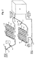
- FIGURE 2 illustrates a perspective view of an assembled magnetic apparatus 50 comprising separation chamber 52 and a bed 58.
- the separation chamber 52 comprises a plurality of magnets 57 and a plurality of channels 55 having an inlet 53 and an outlet 54.
- the bed 58 can be composed of a soft iron magnetic metal.
- the magnets 57 are high energy rare earth magnets and preferably NdFeB or SmCo magnets.
- the magnets 57 have an axis with opposing north and south poles, and one of the poles rests on the magnetic bed 58 while the other pole faces the channels 55.
- Each of the magnets 57 are aligned side-by-side to the other magnets.
- FIGURE 3 illustrates a perspective view of a disassembled magnetic apparatus 50, particularly focusing on the various components of the apparatus 50.
- the bed 58 has a surface upon which a plurality of magnets 57 are aligned.
- the bed 58 has at least two elevated edges 59 and the separation chamber 52 is set between the edges 59 of the bed 58 and above the plurality of magnets 57.
- FIGURE 4 illustrates an alternate embodiment of the magnetic separation apparatus 50 of the present invention.
- the apparatus 50 comprises a separation chamber 52 and a bed 58.
- the separation chamber 52 has a plurality of channels 55 and an inlet 53 and outlet 54.
- the chamber 52 also has a plurality of magnets 57 situated upon the bed 58.
- the bed 58 has at least two elevated edges 59 and apertures 61 on the edges 59.
- the apparatus 50 also comprises a plurality of electromagnetic coils 62, each coil 62 having at least two guide rails 60.
- the coils 62 are attached to the chamber 52 and the guide rails 60 are inserted in the apertures 61 of the edges 59 of the bed 58.
- the coils 62 travel up and down the guide rails 60 determining the distance between the chamber 52 and the magnets 57, thereby allowing the activation and deactivation of the magnetic field of the magnetic apparatus 50.
- FIGURE 5a illustrates a cutaway view of the magnetic apparatus 50 of the present invention in a de-energized or magnetic field deactivated state.
- the magnets 57 are set on the bed 58 which has elevated edges 59.
- the separation chamber 52 is connected to electromagnetic coils 62. There is a distance between the coils 62 and the edges 59 creating a distance between the chamber 52 and the magnets 57 on the bed 58.
- FIGURE 5b illustrates a cutaway view of the magnetic apparatus 50 of the present invention in an energized or magnetic field activated state.
- the coils 62 are in contact with edges 59 thus creating contact between the magnets 57 on the bed 58.
- FIGURES 6a-g illustrate various configurations of the magnets in the present invention.
- FIGURE 6a depicts a plurality of magnets arranged in alternating magnetic poles so that the magnets are aligned side-by-side with a configuration of north-south-north-south.
- FIGURE 6b illustrates the magnets in FIGURE 6a slightly offset from the side-by-side configuration.
- FIGURE 6c depicts a plurality of magnets vertically aligned in alternating poles so that there is a vertical line of north poles aligned side-by-side with a vertical line of south poles.
- FIGURE 6d illustrates a plurality of magnets horizontally aligned in alternating poles so that there is a horizontal line of north poles aligned side-by-side with a horizontal line of south poles.
- FIGURE 6e depicts a slightly offset configuration of FIGURE 6d.
- FIGURE 6f depicts a slightly offset configuration of FIGURE 6c.
- FIGURE 6g illustrates a plurality of magnets arranged so that one magnet having one pole is surrounded by other magnets of opposing poles on four sides.
- FIGURE 7 illustrates another embodiment of the magnetic separation apparatus 50 of the present invention wherein the bed 58 is tilted on one side 70 in relation to the separation chamber 52.
- the tilted side 70 of the bed 58 can be in contact with one side of the chamber 52 and the untilted side 71 of the bed 58 being from about .5 to about 3 cm is distance from the chamber 52.
Abstract
Description
- The present invention relates to a magnetic system and apparatus having a multi-dimensional gradient for the continuous, on-line separation of components from a mixture of chemical entities. The system and apparatus of the present invention can be used specifically to separate blood components from a whole blood sample. The invention also relates to a method of continuously and magnetically separating a component from a mixture of chemical entities using a multi-dimensional gradient, and a method of manufacturing a continuous magnetic separation apparatus.
- The separation and isolation of blood components from a whole blood sample is a significant aspect of the treatment and clinical and laboratory testing of such blood components. There are numerous methods and apparati for the separation of blood components.
- Whole blood can be separated by low speed centrifugation into a cell free fluid called serum (or plasma if a blood anticoagulant is present) and a pellet containing cells and platelets. Plasma is about 92% water and contains electrolytes, lipoproteins, proteins, hormones, other nutrients and vitamins. The lipoproteins are lipid-protein complexes. Lipoproteins are the primary transport molecules for lipids and also transport vitamin E and beta-carotene (provitamin A). Lipoproteins are further divided into very low density lipoprotein, low density lipoprotein and high density lipoprotein. High levels of low density lipoprotein are associated with atherosclerosis and cardiovascular disease. In contrast, high levels of high density lipoprotein are thought to protect against atherosclerosis.
- The primary proteins found in plasma are albumin, globulins, fibrinogen. Albumin is the most abundant plasma protein (about 60%) and is a carrier molecule for nonesterified fatty acids. Albumin also plays a role in maintaining the osmotic pressure of blood. The globulins are further divided into alpha-, beta-, and gamma-globulins. The gamma-globulin fraction contains molecules that function as antibodies in the humoral immune system. Fibrinogen functions in clot formation.
- The red blood cell (or erythocyte) is the primary cell found in blood. This unique cell has a membrane but no other membranous organelles and does not have a cell nucleus. The primary function of red blood cells is oxygen transport to tissues and the removal of carbon dioxide. The oxygen carrying molecule in the red blood cell is hemoglobin. The red blood has a biconcave shape and is extremely deformable and able to move through very small capillaries. In anemia, the number of red blood cells in a given volume of blood is low resulting in a decreased ability to deliver oxygen to tissues. Nutritional and/or genetic factors can contribute to anemia.
- Blood also contains white blood cells and platelets. White blood cells (or leukocytes) include monocytes, lymphocytes, neutrophils, eosinophils, and basophils. Neutrophils, eosinophiles, and basophils (all three are also called granulocytes) as well as monocytes are phagocytic cells. Phagocytic cells and lymphocytes play a key role in the immune system. Platelets function in clot formation.
- Since blood components have magnetization properties, there have been numerous efforts to utilize magnetism to separate and isolate such blood components. The most common problems with the prior art is that they cannot perform the separation in a continuous manner and they do not use a multi-dimensional gradient. In addition, the prior art does not provide a decoupling process and some of the prior art conduct separation in a static stage rather than a constant flow stage.
- EP-A-0672458 discloses a magnetic apparatus with a separation chamber and a plurality of magnets, and a method for separation of components from a mixture of chemical entities.
- U.S. Patent No. 4,910,148 to Sorenson et al. relates to a method and device for separating magnetized particles from biological fluids, particularly white blood cells using a monoclonal antibody to link the cells to magnetic beads. In contrast to the present invention, the Sorenson separation is static (i.e., no flow) and is conducted in a plastic blood bag. The magnetic beads are linked to the cancer white cells by an agitation process and then a magnetic field is applied to keep the white blood cells with the magnetic beads in the disposable plastic bag. The Sorenson device also requires space between the magnets which does not optimize the magnetic gradient (magnetic force). The back plate of the Sorenson device is a soft magnetized material and the magnets are Samruim-Cobalt. Sorenson has a volume limitation since it uses a blood bag (150 ml) and there is no decoupling between the beads and the white blood cells. Matter of fact, the cells remain in the disposable blood bag after separation.
- U.S. Patent No. 5,514,340 to Lansdorp, et al. relates to a device for separating magnetically labeled cells in a sample using an applied magnetic field. Lansdorp uses magnetized screens to attract the magnetic particles allowing the biological fluid to be caught in the magnetic wires of the screen. The magnets used in Lansdorp must constantly be cleaned since there is contact between the magnets and the blood cells.
- U.S. Patent No. 5,567,326 to Ekenberg et al. relates to an apparatus and methods for separating magnetically responsive particles from a non-magnetic test medium in which the magnetically responsive particles are suspended. In Ekenberg, small patch amounts of biological fluid are placed in a tube then a magnetic pin is inserted in the fluid for separation.
- U.S. Patent No. 5,541,072 to Wang et al. relates to methods and devices for separation of magnetic particles and/or magnetic-associated substances from non-magnetic associated substances and media. Unlike the present invention, the Wang method does not utilize the optimum magnetic gradient (magnetic force) available since Wang situates its magnets on two opposing sides.
- U.S. Patent No. 4,988,618 to Li et al. relates to a magnetic separation device for use in immunoassay or hybridization assay procedures. The Li device comprises a base having a plurality of orifices for receiving nonferrous containers which hold the sample and the assay components including ferrous particles. The orifices are surrounded by a plurality of magnets which are spaced about the peripheral of the orifices.
- U.S. Patent No. 4,935,147 to Ullman et al. relates to a method for separating a substance from a liquid medium, particularly applicable for cells and microorganisms from aqueous suspension and also for the determination of a analyte. Although Ullman discusses a method with a reversible non-specific coupling, the method is not continuous nor does it utilize a multi-dimensional gradient.
- The presently claimed invention overcomes the above mentioned problems by providing a system, an apparatus and a method for continuous separation of components from a mixture of chemical entities using a multi-dimensional gradient.
- Accordingly, the object of the present invention is to provide a magnetic apparatus and system having a multi-dimensional gradient for continuous, on-line separation of components from a mixture of chemical entities as defined by the features of
claims 1 and 23, respectively. - Another object of the present invention is to provide an apparatus and system for continuous, on-line magnetic separation of blood components from a whole blood sample.
- Yet another object of the invention is to provide a method for continuously and magnetically separating a component from a mixture of chemical entities utilizing a multi-dimensional gradient, as defined by the features of claim 35.
- A further object of the present invention is to provide a method of manufacturing, a continuous magnetic blood separating apparatus, as defined by the features of
claim 22. - Still another object of the present invention is to provide a system and a method for a continuous magnetic separation of blood components from a whole blood sample using a continuous blood flow and having a decoupling process.
- The present invention relates to a magnetic system having a multi-dimensional gradient for continuous, on-line separation of components from a mixture of chemical entities. The system comprising: (a) at least one mixing chamber for agitating the mixture and magnetic particles, the particles being attached to the components of the mixture upon agitation, and (b) at least one separation chamber. The separation chamber comprises a plurality of magnets and a plurality of channels having an inlet and an outlet. The magnets are arranged on one side of the channels and are in contact with one another to create a magnetic field. The mixture containing the particle attached components are introduced into the inlet of the channels of the separation chamber, and the magnetic field of the magnets captures the particle attached components within the channels and the remaining mixture exits the outlet of the channels of the separation chamber.
- In another embodiment of the invention, the magnetic system further comprises a solution reservoir for introducing solution through the inlet and the channels for flushing out the particle attached components through the outlet of the channels of the separation chamber upon deactivation of the magnetic field. The magnetic system also comprises a decoupling agent reservoir for introducing a decoupling agent to the particle attached components and an additional mixing chamber for agitating the decoupling agent and the particle attached components allowing the separation of the particles and the components. In one embodiment, the decoupling agent attaches to the components and the magnetic particles deattach. The decoupling agent attached components and particle mixture are reintroduced into the separation chamber and the magnets are reactivated to produce the magnetic field which captures the magnetic particles and the remaining decoupling agent/components exit the outlet of the channel of the separation chamber. The separation of the components and magnetic particles can be done in numerous ways. Adjusting the temperature or pressure can physically separate the components and particles. Decoupling agents such as sugar, salt or pH changes can be used to chemically separate the components and particles.
- The magnetic system can also comprise a treatment device for treating the remaining mixture; a collection chamber for reintroducing the components to the treated mixture; and a plurality of directional valves for controlling the flow of the mixture, components, solutions and decoupling agent.
- The separation chamber of the magnetic system comprises a bed for supporting the magnets. The preferred material for the bed is a soft magnetic iron metal.
- The magnets can be any high energy rare earth magnets such as NdFeB or SmCo magnets. Each of the magnets has an axis with opposing north and south poles, one of the poles rests on the bed and the other pole faces the plurality of channels. Each of the magnets are aligned side-by-side to the other magnets. The axis of each of the magnets is perpendicular to the bed. In another embodiment, the axis of each of the magnets is parallel to the axis of the other magnets and perpendicular to the channels.
- The mixture of chemical entities can be a whole blood sample and the components can be any biological micromolecule such as red blood cells, white blood cells, platelets and other plasma borne components.
- In one embodiment, the plurality of magnets can be arranged in alternating magnetic poles so that the magnets are aligned side-by-side with a configuration of north-south-north-south, or are slightly offset from the side-by-side configuration.
- In yet another embodiment, the plurality of magnets are vertically aligned in alternating poles so that there is a vertical line of north poles aligned side-by-side with a vertical line of south poles, or are slightly offset from the side-by-side configuration.
- In still another embodiment, the plurality of magnets are horizontally aligned in alternating poles so that there is a horizontal line of north poles aligned side-by-side with a horizontal line of south poles, or are slightly offset from the side-by-side configuration.
- In a further embodiment, the magnets are arranged so that one magnet having one pole is surrounded by other magnets of opposing poles on four sides.
- In one embodiment, each of the channels has varying widths, and the channel width is increased at an entrance near the inlet and the channel width is tapered at an exit near the outlet. The plurality of magnets can also be situated underneath the channel near the inlet and the outlet of the separation chamber. The bed can be tilted on one side in relation to the separation chamber. The tilted side of the bed is in contact with one side of the separation chamber and the untilted side of said bed being from about .5 to about 3 cm in distance from the separation chamber.
- The magnetic system comprises a switching mechanism for bringing the separation chamber in contact with the plurality of magnets and the magnet bed thereby activating the magnetic field produced by the magnets and for distancing the separation chamber from the plurality of the magnets and the bed thereby deactivating the magnetic field. The switching mechanism can include, but is not limited to the following: a plurality of guide rails and electromagnetic coils, rack and pinion, or belt driven mechanism.
- The magnetic particles, in one of the embodiments, can be microspheres which are ligand covered and coupling agent bound. The ligand is protein and the coupling agent is lectin.
- The present invention relates to a magnetic apparatus having a multi-dimensional gradient for separation of components from a mixture of chemical entities. The apparatus comprises a separation chamber comprising a plurality of magnets and a plurality of channels having an inlet and an outlet. The magnets are arranged on one side of the channels and are in contact with one another to create a magnetic field. A mixture containing a magnetic particle attached components is introduced into the inlet of the channels of the separation chamber and the magnetic field of the magnets captures the particle attached components within the channels and the remaining mixture exits the outlet of the channels of the separation chamber.
- The separation chamber comprises a bed for supporting the magnets and the bed is preferably composed of a soft magnetic iron metal. The bed upon which the magnets are set can be flat or staggered.
- The magnets are high energy rare earth magnets, and preferably NdFeB or SmCo magnets. Each of the magnets has an axis with opposing north and south poles, one of the poles rests on the magnetic bed and the other pole faces the plurality of the channels, and each of the magnets are aligned side-by-side to the other magnets. The axis of each of the magnets is perpendicular to the bed and in other embodiments, the axis can be parallel to the axis of the other magnets and perpendicular to the channels.
- In another embodiment, the plurality of magnets are arranged in alternating magnetic poles so that the magnets are aligned side-by-side with a configuration of north-south-north-south, or are slightly offset from the side-by-side configuration.
- In yet another embodiment, the plurality of magnets are vertically aligned in alternating poles so that there is a vertical line of north poles aligned side-by-side with a vertical line of south poles, or are slightly offset from the side-by-side configuration.
- In still another embodiment, the plurality of magnets are horizontally aligned in alternating poles so that there is a horizontal line of north poles aligned side-by-side with a horizontal line of south poles, or are slightly offset from the side-by-side configuration.
- In a further embodiment, the magnets are arranged so that one magnet having one pole is surrounded by other magnets of opposing poles on four sides.
- In one embodiment of the invention, each of the channels has varying widths and the channel width is increased at an entrance near the inlet and the channel width is tapered at an exit near the outlet. The plurality of magnets can be situated underneath the channel near the inlet and the outlet of the separation chamber. The bed can be tilted on one side in relation to the separation chamber. The tilted side of the bed is in contact with one side of the separation chamber and the untilted side of the magnetic bed is from about .5 to about 3 cm in distance from the separation chamber.
- The magnetic apparatus comprises a switching mechanism for bringing the separation chamber in contact with the plurality of magnets and the magnetic bed thereby activating the magnetic field produced by the magnets, or for distancing the separation chamber from the plurality of magnets and the bed thereby deactivating the magnetic field. The switching mechanism can be a plurality of guide rails and electromagnetic coils, rack and pinions or belt driven.
- The mixture of chemical entities can be a whole blood sample and the components can be any biological micromolecules such as red blood cells, white blood cells, platelets and other plasma borne components.
- The present invention provides a magnetic system having a multi-dimensional gradient for continuous, on-line separation of blood components from whole blood. The system comprising: (a) at least one mixing chamber for agitating a blood sample and magnetic particles, the particles being attached to a blood component of the blood sample upon agitation, and (b) at least one separation chamber. The separation chamber comprises a plurality of magnets and a plurality of channels having an inlet and an outlet. The magnets are arranged on one side of the channels and are in contact with one another to create a magnetic field. The blood samples containing the particle attached blood components are introduced into the inlet of the channels of the separation chamber, and the magnetic field of the magnets captures the particle attached blood components within the channels and the remaining blood sample exits the outlet of the channels of the separation chamber.
- In another embodiment of the invention, the magnetic system further comprises a solution reservoir for introducing solution through the inlet and the channels for flushing out the particle attached blood components through the outlet of the channels of the separation chamber upon deactivation of the magnetic field. The magnetic system comprises a decoupling agent reservoir for introducing a decoupling agent to the particle attached blood components and an additional mixing chamber for agitating the decoupling agent and the particle attached blood components allowing the separation of the particle and the components. In one embodiment, the decoupling agent attaches to the blood components and the magnetic particle to deattach. The decoupling agent attached blood components and microspheres mixture are reintroduced into the separation chamber and the magnets are reactivated to produce the magnetic field which captures the particles and the remaining decoupling agent/blood components exit the outlet of the channel of the separation chamber. The decoupling agent can either be physical such as pressure and temperature or chemical such as sugar, salt or pH changes.
- The magnetic system can also comprise a treatment device for treating the remaining blood sample; a collection chamber for reintroducing the blood components to the remaining blood sample; and a plurality of directional valves for controlling the flow of the blood sample, blood components, solutions and decoupling agent.
- The channels can have numerous shapes including serpentine configurations. In one embodiment, each of the channels has varying widths, and the channel width is increased at an entrance near the inlet and the channel width is tapered at an exit near the outlet. The plurality of magnets can also be situated underneath the channel near the inlet and the outlet of the separation chamber. The bed can be tilted on one side in relation to the separation chamber. The tilted side of the bed is in contact with one side of the separation chamber and the untilted side of said bed being from about .5 to about 3 cm in distance from the separation chamber.
- The present invention also provides a magnetic apparatus having a multi-dimensional gradient for separation of blood components from whole blood. The apparatus comprises a separation chamber comprising a plurality of magnets and a plurality of channels having an inlet and an outlet. The magnets are arranged on one side of the channels and are in contact with one another to create a magnetic field. A blood sample containing magnetic particle attached blood components is introduced into the inlet of the channels of the separation chamber and the magnetic field of the magnets captures the particle attached blood components within the channels and the remaining blood sample exits the outlet of the channels of the separation chamber.
- The separation chamber comprises a bed for supporting the magnets and the bed is composed of a magnetizable material such as soft iron metal.
- The present invention also provides method of continuously and magnetically separating a component from a mixture of chemical entities utilizing a multi-dimensional gradient. The method comprising the steps of: a) introducing a blood sample to a plurality of magnetic microspheres; b) agitating the blood sample and microspheres and inducing the microspheres to attach to blood components of the blood sample; c) providing a separation chamber, the separation chamber comprising a plurality of magnets and a plurality of channels having an inlet and an outlet, the magnets being arranged on one side of said channels and in contact with one another to create a magnetic field; d) introducing the blood sample containing the microsphere attached blood components into the inlet and through the channels of the separation chamber; e) activating the magnets to produce a magnetic field to capture the microsphere attached blood components within the channels; and f) allowing the remaining blood sample to exit the outlet of the channels of the separation chamber.
- The method can further comprise the step of (g) providing a solution reservoir and upon deactivation of the magnetic field, introducing solution through the inlet and the channels flushing out the microsphere attached blood components through the outlet. The method can also further comprise the steps of (h) introducing a decoupling agent to the microsphere attached blood components and (i) separating the magnetic particles and components using the decoupling agent, and (j) reintroducing the decoupling agent attached blood components and particles mixture into the separation chamber and reactivating the magnetic field allowing the capture of the particles and exiting of the decoupling agent attached blood components from the separation chamber. In one embodiment, the separation of the particles and the components by allowing the decoupling agent to attach to the blood components and microspheres to deattach. The method can further comprise the step of treating the remaining blood sample of step (f) and step (k) wherein the magnetic field is deactivated and solution is introduced into the inlet and through the channels flushing out the magnetic particles through the outlet.
- In one embodiment, the method can further comprise the step of reintroducing the blood components to the remaining blood sample using a collection chamber and controlling the travel of the blood sample, the blood components, solutions and decoupling agent using a plurality of directional valves.
- The method can also comprise the step of providing the separation chamber with a bed for supporting the magnets. The bed is preferably composed of a magnetizable material such as soft iron metal. The magnets are a high energy rare earth magnets and preferably NdFeB or SmCo magnets.
- Each of the magnets has an axis with opposing north and south poles and further comprises the step of arranging the magnets so that one of the poles rests on the magnetic bed and the other pole faces the plurality of the channels and aligning each of the magnets side-by-side to the other magnets. The axis of each magnet is perpendicular to the magnetic bed. In one embodiment, the axis of each of the magnets is parallel to the axis of the other magnets and perpendicular to the channels.
- In one embodiment, the method comprises arranging the magnets in alternating magnetic poles with a configuration of north-south-north-south, or slightly offset from the side-by-side configuration.
- In another embodiment the method comprises the step of vertically aligning the plurality of magnets in alternating poles so that there is a vertical line of north poles aligned side-by-side with a vertical line of south poles, or slightly offset from the side-by-side configuration.
- In still another embodiment, the method comprises the step of horizontally aligning the plurality of magnets in alternating poles so that there is a horizontal line of north poles aligned side-by-side with a horizontal line of south poles, or slightly offset from the side-by-side configuration.
- In a further embodiment, the method comprises arranging the magnets so that one magnet having one pole is surrounded by other magnets of opposing poles on four sides.
- The method can further comprise the step of varying the widths of the channels. The channel width is increased at an entrance near the inlet and the channel width is tapered at an exit near the outlet. The method can also comprise situating the plurality of magnets underneath the channel near the inlet and the outlet of the separation chamber. The method also includes tilting the bed on one side in relation to the separation chamber. The tilted side of the bed is in contact with one side of the separation chamber and the untilted side of said bed is from about .5 to about 3 cm in distance from the separation chamber.
- The method comprises the step of providing a switching mechanism for bringing the separation chamber in contact with the bed and the magnets, thereby activating the magnetic field. The method can also include providing guide rails and electromagnetic coils for distancing the separation chamber and the magnets/bed thereby deactivating the magnetic field.
- The present invention also provides method of manufacturing a continuous blood separating apparatus. The method comprising the steps of: a) providing a separation chamber, the separation chamber comprising a plurality of magnets and a plurality of channels having an inlet and outlet, the magnets being arranged on one side of the channels and being in contact with one another to create a magnetic field; and b) providing a bed for supporting the magnets.
- A more complete appreciation of the present invention and many of the attendant advantages thereof will be readily understood by reference to the following description when considered in connection with the accompanying drawings in which:
- FIGURE 1 illustrates a perspective view of the magnetic system of the presently claimed invention.
- FIGURE 2 illustrates a perspective view of the magnetic apparatus of the present invention.
- FIGURE 3 illustrates a perspective view of the magnetic apparatus of the present invention including the separation chamber, the bed and the plurality of magnets.
- FIGURE 4 illustrates a perspective view of one embodiment of the switching mechanism of the magnetic apparatus of the present invention including guide rails and electromagnetic coils.
- FIGURE 5a illustrates a cutaway view of the magnetic apparatus with guide rails and electromagnetic coils in a de-energized state.
- FIGURE 5b illustrates a cutaway view of the magnetic apparatus in an energized state.
- FIGURES 6 a-g illustrate overhead views of the various magnetic configurations of the magnetic apparatus of the present invention.
- FIGURE 7 illustrates a perspective view of the magnetic apparatus wherein the bed is in a tilted configuration.
- Referring now to the drawings wherein like reference numerals designate identical or corresponding parts throughout the several views and more particularly to FIGURE 1 wherein the system and method of the present invention are illustrated. Lectin is bound to a protein covered magnetic particle such as a microsphere in mixing
chamber 10 and the lectin-bound microsphere is agitated with a whole blood sample in mixingchamber 12. The agitation causes the microspheres to be bound to blood components (red blood cells) of the whole blood sample. The blood sample containing the microsphere attached blood components are then introduced into a firstmagnetic apparatus 20 having aseparation chamber 22. The sample enters thechamber 22 through itsinlet 23. Thechamber 22 has a plurality ofchannels 25 and a plurality ofmagnets 27. Themagnets 27 are in contact with one another. The magnets create a magnetic field and the magnetic field captures the microsphere attached blood components with thechannels 25 and the remaining blood (white blood cells, platelets and plasma) travels through thechannels 25 and exits theoutlet 24 of theseparation chamber 22. - The exiting remaining blood sample then enters a
treatment device 30 such as a UVAR photophoresis system. The magnetic field is deactivated and a solution is introduced into theseparation chamber 22 from asolution reservoir 14. The solution enters toinlet 23, travels through thechannels 25 and flushes out the microsphere attached blood components through theoutlet 24 of theseparation chamber 22. The microsphere attached blood components travel throughdirectional valve 16 and enter another mixingchamber 17 where a decoupling agent (such as sugar or salt) from thedecoupling agent reservoir 18 is introduced. In mixingchamber 17, the microsphere attached blood components and the decoupling agent are agitated causing the decoupling agent to attach to the blood components and the microspheres to deattach. The decoupling agent attached blood components and microspheres mixture is introduced to a secondmagnetic apparatus 40 having aseparation chamber 42. The mixture enters thechamber 42 through itsinlet 43. The mixture flows through a plurality ofchannels 45 and a plurality ofmagnets 47 situated underneath thechannels 45. The magnetic field of themagnets 47 are activated and the microspheres are captured within theseparation chamber 42. The decoupling agent attached blood components travel through thechannels 45 andexit outlet 44 of thechamber 42. The treated blood and blood components are then reintroduced to one another usingcollection chamber 19. - FIGURE 2 illustrates a perspective view of an assembled
magnetic apparatus 50 comprisingseparation chamber 52 and abed 58. Theseparation chamber 52 comprises a plurality ofmagnets 57 and a plurality ofchannels 55 having aninlet 53 and anoutlet 54. Thebed 58 can be composed of a soft iron magnetic metal. Themagnets 57 are high energy rare earth magnets and preferably NdFeB or SmCo magnets. Themagnets 57 have an axis with opposing north and south poles, and one of the poles rests on themagnetic bed 58 while the other pole faces thechannels 55. Each of themagnets 57 are aligned side-by-side to the other magnets. - FIGURE 3 illustrates a perspective view of a disassembled
magnetic apparatus 50, particularly focusing on the various components of theapparatus 50. Thebed 58 has a surface upon which a plurality ofmagnets 57 are aligned. Thebed 58 has at least twoelevated edges 59 and theseparation chamber 52 is set between theedges 59 of thebed 58 and above the plurality ofmagnets 57. - FIGURE 4 illustrates an alternate embodiment of the
magnetic separation apparatus 50 of the present invention. Theapparatus 50 comprises aseparation chamber 52 and abed 58. Theseparation chamber 52 has a plurality ofchannels 55 and aninlet 53 andoutlet 54. Thechamber 52 also has a plurality ofmagnets 57 situated upon thebed 58. Thebed 58 has at least twoelevated edges 59 andapertures 61 on theedges 59. Theapparatus 50 also comprises a plurality ofelectromagnetic coils 62, eachcoil 62 having at least twoguide rails 60. Thecoils 62 are attached to thechamber 52 and the guide rails 60 are inserted in theapertures 61 of theedges 59 of thebed 58. Thecoils 62 travel up and down the guide rails 60 determining the distance between thechamber 52 and themagnets 57, thereby allowing the activation and deactivation of the magnetic field of themagnetic apparatus 50. - FIGURE 5a illustrates a cutaway view of the
magnetic apparatus 50 of the present invention in a de-energized or magnetic field deactivated state. Themagnets 57 are set on thebed 58 which has elevated edges 59. Theseparation chamber 52 is connected toelectromagnetic coils 62. There is a distance between thecoils 62 and theedges 59 creating a distance between thechamber 52 and themagnets 57 on thebed 58. - FIGURE 5b illustrates a cutaway view of the
magnetic apparatus 50 of the present invention in an energized or magnetic field activated state. Thecoils 62 are in contact withedges 59 thus creating contact between themagnets 57 on thebed 58. - FIGURES 6a-g illustrate various configurations of the magnets in the present invention. FIGURE 6a depicts a plurality of magnets arranged in alternating magnetic poles so that the magnets are aligned side-by-side with a configuration of north-south-north-south. FIGURE 6b illustrates the magnets in FIGURE 6a slightly offset from the side-by-side configuration. FIGURE 6c depicts a plurality of magnets vertically aligned in alternating poles so that there is a vertical line of north poles aligned side-by-side with a vertical line of south poles. FIGURE 6d illustrates a plurality of magnets horizontally aligned in alternating poles so that there is a horizontal line of north poles aligned side-by-side with a horizontal line of south poles. FIGURE 6e depicts a slightly offset configuration of FIGURE 6d. FIGURE 6f depicts a slightly offset configuration of FIGURE 6c. FIGURE 6g illustrates a plurality of magnets arranged so that one magnet having one pole is surrounded by other magnets of opposing poles on four sides.
- FIGURE 7 illustrates another embodiment of the
magnetic separation apparatus 50 of the present invention wherein thebed 58 is tilted on oneside 70 in relation to theseparation chamber 52. The tiltedside 70 of thebed 58 can be in contact with one side of thechamber 52 and theuntilted side 71 of thebed 58 being from about .5 to about 3 cm is distance from thechamber 52.
Claims (69)
- A magnetic apparatus (50) having a multi-dimensional gradient for separation of components from a mixture of chemical entities, said system comprising:(A) a separation chamber (52) comprising a plurality of channels (55) and having an inlet (53) and an outlet (54), and(B) a plurality of magnets (57) being arranged external to and on a bed (58) on one side of said separation chamber (52), said magnets (57) being in magnetic contact with one another to create a magnetic field,and characterized in that said apparatus (50) further comprises:(C) a switching mechanism for activating and deactivating the magnetic field produced in said separation chamber (52) by said magnets (57).
- The magnetic apparatus (50) of claim 1 wherein said bed (58) is composed of a magnetizable soft iron metal.
- The magnetic apparatus (50) of claim 1 wherein said magnets (57) are NdFeB magnets.
- The magnetic apparatus (50) of claim 1 wherein said magnets (57) are SmCo magnets.
- The magnetic apparatus (50) of claim 1 wherein each of said magnets (57) has an axis with opposing north and south poles, one of said poles rests on the top surface of said bed (58) and the other pole faces said plurality of channels (55), said axis of each of said magnets (57) being perpendicular to said bed (58), each of said magnets (57) being aligned side-by-side to other said magnets (57).
- The magnetic apparatus (50) of claim 5 wherein said axis of each of said magnets (57) being parallel to said axis of other magnets (57) and perpendicular to said channels (55).
- The magnetic apparatus (50) of claim 5 wherein said plurality of said magnets (57) are arranged in alternating magnetic poles so that said magnets (57) are aligned side-by-side with a configuration of north-south-north-south.
- The magnetic apparatus (50) of claim 7 wherein said magnets (57) are slightly offset from the side-by-side configuration.
- The magnetic apparatus (50) of claim 5 wherein said plurality of said magnets (57) are vertically aligned in alternating poles so that there is a vertical line of north poles aligned side-by-side with a vertical line of south poles.
- The magnetic apparatus (50) of claim 9 wherein said magnets (57) are slightly offset from the side-by-side configuration.
- The magnetic apparatus (50) of claim 5 wherein said plurality of said magnets (57) are horizontally aligned in alternating poles so that there is a horizontal line of north poles aligned side-by-side with a horizontal line of south poles.
- The magnetic apparatus (50) of claim 11 wherein said plurality of said magnets (57) are slightly offset from the side-by-side configuration.
- The magnetic apparatus (50) of claim 5 wherein said magnets are arranged so that one magnet (57) having one pole is surrounded by other magnets (57) of opposing pole on four sides.
- The magnetic apparatus (50) of claim 1 wherein each of said channels (55) has varying widths, said channel width is increased at an entrance near said inlet (53) and said channel width is tapered at an exit near said outlet (54).
- The magnetic apparatus (50) of claim 14 wherein said tilted side of said bed (58) is in contact with one side of said separation chamber (52) and an untilted side of said bed (58) being 0.5 to 3 cm in distance from said separation chamber (52).
- The magnetic apparatus (50) of claim 1 wherein said plurality of said magnets (57) are situated underneath said channel near said inlet (53) and said outlet of said separation chamber (52).
- The magnetic apparatus (50) of claim 1 wherein said bed (58) is tilted on one side in relation to said separation chamber (52).
- The magnetic apparatus (50) of claim 17, wherein said tilted side of said bed (58) is in contact with one side of said separation chamber (52) and an untilted side of said bed (58) is from 0.5cm to 3cm in distance from said separation chamber (52).
- The magnetic apparatus (50) of claim 1 wherein said magnets (57) are in magnetic contact with more than one other of said magnets (57).
- The magnetic apparatus (50) of claim 1 wherein said switching mechanism is for bridging said separation chamber (52) into contact with said bed (58) for activating said magnetic field produced in said separation chamber (52) by said magnets (57) and for distancing said separation chamber (52) away from said bed (58) for deactivating said magnetic field produced in said separation chamber (52) by said magnets (57).
- The magnetic apparatus (50) of claim 20 wherein said switching mechanism comprises a plurality of guide rails (60) and electromagnetic coils (62).
- A method of manufacturing the magnetic apparatus (50) of any one of claims 1 to 20,
said method comprising the steps of :(a) providing a separation chamber comprising a plurality of channels and having an inlet and an outlet(b) providing a plurality of magnets being arranged external to and on a bed on one side of said separation chamber, said magnets being in magnetic contact with one another to create a magnetic field,(c) providing a switching mechanism for activating and deactivating the magnetic field produced in said separation chamber by said magnets. - A magnetic system having a multi-dimensional gradient for continuous, on-line separation of a component from a mixture of chemical entities, said system comprising:(A) at least one mixing chamber for agitating a mixture of chemical entities and magnetic particles, the particles being attached to a component of the mixture upon agitation, and(B) the magnetic separation apparatus (50) of any one of claims 1 to 20.
- The magnetic system of claim 23 further comprising a solution reservoir for introducing solution through said inlet (53) and said channels (55) for flushing out the magnetic particle attached components through said outlet (54) of said channels of said separation chamber (52) upon deactivation of the magnetic field produced by said magnets (57).
- The magnetic system of claim 24 further comprising a decoupling agent reservoir for introducing a decoupling agent to the magnetic particle attached components.
- The magnetic system of claim 25 further comprising an additional mixing chamber for agitating the decoupling agent and the magnetic particle attached components allowing the separation of the magnetic particle and components.
- The magnetic system of claim 26 wherein the separation of the magnetic particles and components is caused by the decoupling agent attaching to the components and causing the magnetic particles to detach.
- The magnetic system of claim 26, configured to reintroduce the components and magnetic particles mixture into said separation chamber (52) and reactivate said magnets (57) to produce the magnetic field for capturing the magnetic particles and permitting the components to exit said outlet (54) of said channel of said separation chamber (52).
- The magnetic system of claim 28 further comprising a collection chamber for reintroducing the components to the remaining mixture.
- The magnetic system of claim 28 further comprising a plurality of directional valves for controlling the flow of mixture, components, solutions and decoupling agent.
- The magnetic system of claim 25 wherein the decoupling agent is sugar.
- The magnetic system of claim 23 further comprising a treatment device for treating the remaining mixture.
- The magnetic system of claim 23 wherein the magnetic particle is a microsphere that is ligand covered and coupling agent bound.
- The magnetic system of claim 33 wherein ligand is a protein and said coupling agent is lectin.
- A method of continuously and magnetically separating a component from a mixture of chemical entities utilizing a multi-dimensional gradient, said method comprising the steps of:(a) introducing a mixture of chemicals entities to a plurality of magnetic particles;(b) agitating the mixture and magnetic particles and inducing the magnetic particles to attach to a component of said mixture;(c) providing a first magnetic separation apparatus (20) comprising:(1) a first separation chamber (22) having a plurality of channels (25) and an inlet (23) and an outlet (24), and(2) a first plurality of magnets (27) being arranged external and to one side of said first separation chamber (22), said magnets (27) being in magnetic contact with one another to create a magnetic field;(d) introducing the mixture containing the magnetic-particle-attached component into said inlet (23) and through said channels (25) of said first separation chamber (22);(e) activating said first plurality of magnets (27) to produce a magnetic field to capture said magnetic-particle-attached component within said channels (25) and thereby creating a remaining mixture; and(f) allowing the remaining mixture to exit said outlet (24) of said channels (25) of said first separation chamber (22),and characterized in that:the first magnetic separation apparatus (20) further comprises a first switching mechanism for activating and deactivating the magnetic field produced in the first separation chamber (22) by said magnets (27).
- The method of claim 35 further comprising the step of (g) providing a solution reservoir (14) and upon deactivation of said magnetic field, introducing solution through said inlet (23) and said channels (25) flushing out the magnetic-particle-attached component through said outlet.
- The method of claim 35 further comprising the step of (h) introducing a decoupling agent to the magnetic-particle-attached component.
- The method of claim 37 further comprising the step of (i) separating the magnetic particles from said component using the decoupling agent.
- The method of claim 38 wherein the separation of said component and the magnetic particles is caused by the decoupling agent attaching to said component and causing the magnetic particles to deattach.
- The method of claim 38 further comprising the steps of:(j) providing a second magnetic separation apparatus (40) comprising:(1) a second separation chamber (42) comprising a plurality of channels (45) and having an inlet (43) and an outlet (44),(2) a second plurality of magnets (47) being arranged external to and on one side of said separation chamber (42), said magnets (47) being in magnetic contact with one another to create a magnetic field, and(3) a second switching mechanism for activating and deactivating the magnetic field produced in said separation chamber (42) by said magnets (47);(k) introducing the separated component and said magnetic particles into said inlet (43) and through said channels (45) of said second separation chamber (42);(l) activating said second plurality of magnets (47) to capture the magnetic particles; and(m) allowing the remaining mixture containing said separated component to exit said outlet (44) of said channels (45) of said second separation chamber (42).
- The method of claim 40 wherein said second magnetic separation apparatus (40) and said first magnetic separation apparatus (20) are one and the same apparatus.
- The method of claim 37 wherein the decoupling agent is sugar.
- The method of claim 37 further comprising the step of controlling the flow of the mixture, the remaining mixture and decoupling agent.
- The method of claim 40 further comprising the step of (k) deactivating said magnetic field and introducing solution through said second inlet (43) and said second channels (45) flushing out said magnetic particles through said second outlet (44).
- The method of claim 35 further comprising the step of treating the remaining mixture of step (f).
- The method of claim 45 further comprising the step of recombining said separated component with the remaining mixture of step (f) using a collection chamber (19).
- The method of claim 35 comprising the step providing said first separation chamber (22) with a bed for supporting said first plurality of magnets (27).
- The method of claim 47 wherein the bed is composed of a magnetizable soft iron metal.
- The method of claim 35 wherein each of said first plurality of magnets (27) has opposing north and south poles, the axis of each of said first plurality of magnets (27) being perpendicular to said bed.
- The method of claim 49, wherein said axis of each of said first plurality of magnets (27) being parallel to said axis of the other of said first plurality of magnets (27) and perpendicular to said channels (25).
- The method of claim 49 further comprising the step of arranging said first plurality of magnets (27) so that one of said poles rests on a top surface of said bed and the other pole faces said plurality of channels (25) and aligning each of said first plurality of magnets (27) in a side-by-side configuration to the other said first plurality of magnets (27).
- The method of claim 49 further comprising the step of arranging said first plurality of magnets (27) in alternating magnetic poles with a configuration of a north-south-north-south.
- The method of claim 51 wherein said first plurality of magnets (47) are slightly offset from said side-by-side configuration.
- The method of claim 49 further comprising the step of tilting said bed on one side in relation to said first separation chamber (22).
- The method of claim 54 wherein said tilted side of said bed is in contact with one side of said first separation chamber (22) and an untilted side of said bed being from 0.5 to 3 cm in distance from said first separation chamber (22).
- The method of claim 49 further comprising the step of having the first switching mechanism bring said first separation chamber (22) in contact with said bed and said first plurality of magnets (27) thereby activating the magnetic field produced by the first plurality of magnets (27) and separating said first separation chamber (22) from said first plurality of magnets (27) and said bed thereby deactivating the magnetic field.
- The method of claim 47 further comprising the step of vertically aligning said first plurality of magnets (27) in alternating poles so that there is a vertical line of north poles aligned in a side-by-side configuration with a vertical line of south poles.
- The method of claim 57 wherein said first plurality of magnets (27) and slightly offset from the side-by-side configuration.
- The method of claim 47 further comprising the step of horizontally aligning said first plurality of said magnets (27) in alternating poles so that there is a horizontal line of north poles aligned in a side-by-side configuration with a horizontal line of south poles.
- The method of claim 59 wherein said first plurality of magnets (27) are slightly offset from said side-by-side configuration.
- The method of claim 47 further comprising the step of arranging said first plurality of magnets (27) so that one of said first plurality of magnets (27) is surrounded by other of said first plurality of magnets (27) of opposing poles on four sides.
- The method of claim 35 further comprising the step of varying the widths of the first channels (25), said channel width is increased at an entrance near said first inlet (23) and said channel width is tapered at an exit near said first outlet (24).
- The method of claim 35 further comprising the step of situating said first plurality of magnets (27) underneath said at least one of said first channels (25) near said inlet and said outlet (24) of said first separation chamber (22).
- The method of claim 35 wherein the magnetic particle is a microsphere that is ligand covered and coupling agent bound.
- The method of claim 64 wherein the ligand is a protein and the coupling agent is a lectin.
- The method of claim 35 wherein said component is selected from the group consisting of red blood cells, white blood cells, platelets and plasma borne components.
- The method of claim 35 wherein said component comprises red blood cells.
- The method of claim 35 wherein said component comprises white blood cells.
- The method of claim 35 wherein the mixture of chemical entities is a whole blood sample.
Applications Claiming Priority (3)
| Application Number | Priority Date | Filing Date | Title |
|---|---|---|---|
| US09/027,084 US6036857A (en) | 1998-02-20 | 1998-02-20 | Apparatus for continuous magnetic separation of components from a mixture |
| US27084 | 1998-02-20 | ||
| PCT/US1999/003579 WO1999042219A1 (en) | 1998-02-20 | 1999-02-19 | Continuous magnetic separation of components from a mixture |
Publications (2)
| Publication Number | Publication Date |
|---|---|
| EP1056544A1 EP1056544A1 (en) | 2000-12-06 |
| EP1056544B1 true EP1056544B1 (en) | 2005-09-21 |
Family
ID=21835596
Family Applications (1)
| Application Number | Title | Priority Date | Filing Date |
|---|---|---|---|
| EP99934256A Expired - Lifetime EP1056544B1 (en) | 1998-02-20 | 1999-02-19 | Continuous magnetic separation of components from a mixture |
Country Status (16)
| Country | Link |
|---|---|
| US (3) | US6036857A (en) |
| EP (1) | EP1056544B1 (en) |
| JP (2) | JP4642227B2 (en) |
| CN (1) | CN1263548C (en) |
| AT (1) | ATE304897T1 (en) |
| AU (1) | AU3301999A (en) |
| CA (1) | CA2320929C (en) |
| CZ (1) | CZ302485B6 (en) |
| DE (1) | DE69927359T2 (en) |
| ES (1) | ES2249902T3 (en) |
| HK (1) | HK1032554A1 (en) |
| HU (1) | HU227544B1 (en) |
| IL (3) | IL157807A (en) |
| NO (1) | NO320231B1 (en) |
| TR (3) | TR200002375T2 (en) |
| WO (1) | WO1999042219A1 (en) |
Cited By (2)
| Publication number | Priority date | Publication date | Assignee | Title |
|---|---|---|---|---|
| WO2013126774A2 (en) * | 2012-02-24 | 2013-08-29 | President And Fellows Of Harvard College | Microfluidic devices for capture of target species |
| US11112410B2 (en) | 2016-04-13 | 2021-09-07 | President And Fellows Of Harvard College | Methods for capturing, isolation, and targeting of circulating tumor cells and diagnostic and therapeutic applications thereof |
Families Citing this family (105)
| Publication number | Priority date | Publication date | Assignee | Title |
|---|---|---|---|---|
| US6616623B1 (en) * | 1997-07-02 | 2003-09-09 | Idializa Ltd. | System for correction of a biological fluid |
| US8722422B2 (en) | 1999-09-03 | 2014-05-13 | Therakos, Inc. | Uninterrupted flow pump apparatus and method |
| US6495366B1 (en) * | 1999-09-03 | 2002-12-17 | Therakos, Inc. | Uninterrupted flow pump apparatus and method |
| US6692952B1 (en) * | 1999-11-10 | 2004-02-17 | Massachusetts Institute Of Technology | Cell analysis and sorting apparatus for manipulation of cells |
| US20020001855A1 (en) * | 2000-03-22 | 2002-01-03 | Prentiss Mara G. | Methods and apparatus for parallel magnetic biological analysis and manipulation |
| WO2001087458A1 (en) * | 2000-05-12 | 2001-11-22 | University Of Cincinnati | Magnetic bead-based arrays |
| US20040048354A1 (en) * | 2000-08-21 | 2004-03-11 | Darashkevitch Oleg N. | Method and device for simultaneous detection of multiple components in a mixture |
| US6689615B1 (en) | 2000-10-04 | 2004-02-10 | James Murto | Methods and devices for processing blood samples |
| US6913697B2 (en) | 2001-02-14 | 2005-07-05 | Science & Technology Corporation @ Unm | Nanostructured separation and analysis devices for biological membranes |
| US20020166760A1 (en) * | 2001-05-11 | 2002-11-14 | Prentiss Mara G. | Micromagentic systems and methods for microfluidics |
| US7255793B2 (en) * | 2001-05-30 | 2007-08-14 | Cort Steven L | Methods for removing heavy metals from water using chemical precipitation and field separation methods |
| US7081489B2 (en) * | 2001-08-09 | 2006-07-25 | Florida State University Research Foundation | Polymeric encapsulation of nanoparticles |
| US7329392B2 (en) * | 2001-10-19 | 2008-02-12 | Sri International | Device and method for handling reaction components |
| US20040234898A1 (en) * | 2002-02-06 | 2004-11-25 | Batishko Charles R. | Magnetic flowcell systems and methods |
| US7005408B2 (en) | 2002-05-01 | 2006-02-28 | Mcneil-Ppc, Inc. | Warming and nonirritating lubricant compositions and method of comparing irritation |
| ATE531257T1 (en) | 2002-09-27 | 2011-11-15 | Gen Hospital Corp | MICROFLUIDIC DEVICE FOR CELL SEPARATION AND USES THEREOF |
| US6989196B2 (en) * | 2002-10-02 | 2006-01-24 | Florida State University Research Foundation | Microencapsulation of magnetic material using heat stabilization |
| EP1580555B1 (en) * | 2002-11-07 | 2014-02-12 | Mitsubishi Chemical Medience Corporation | Magnetic material for collecting magnetic particles and utilization thereof |
| US20040157219A1 (en) * | 2003-02-06 | 2004-08-12 | Jianrong Lou | Chemical treatment of biological samples for nucleic acid extraction and kits therefor |
| WO2004077021A2 (en) * | 2003-02-27 | 2004-09-10 | Lesko Stephen A | Standardized evaluation of therapeutic efficacy based on cellular biomarkers |
| AU2003209572A1 (en) * | 2003-03-08 | 2004-09-28 | Ecole Polytechnique Federale De Lausanne (Epfl) | Magnetic bead manipulation and transport device |
| WO2004113877A1 (en) * | 2003-06-13 | 2004-12-29 | The General Hospital Corporation | Microfluidic systems for size based removal of red blood cells and platelets from blood |
| RU2252037C1 (en) * | 2003-10-14 | 2005-05-20 | Германов Евгений Павлович | System for correcting biological fluid |
| FI20031635A0 (en) * | 2003-11-11 | 2003-11-11 | Thermo Electron Oy | Particle Separator |
| FR2863626B1 (en) * | 2003-12-15 | 2006-08-04 | Commissariat Energie Atomique | METHOD AND DEVICE FOR DIVIDING A BIOLOGICAL SAMPLE BY MAGNETIC EFFECT |
| US20050266394A1 (en) * | 2003-12-24 | 2005-12-01 | Massachusette Institute Of Technology | Magnetophoretic cell clarification |
| CN1311878C (en) * | 2003-12-25 | 2007-04-25 | 东南大学 | Nano magnetic particle in vivo collector and collecting method |
| JP2007533305A (en) * | 2004-03-03 | 2007-11-22 | ザ ジェネラル ホスピタル コーポレーション | Magnetic apparatus for isolating cells and biomolecules in a microfluidic environment |
| US7803262B2 (en) * | 2004-04-23 | 2010-09-28 | Florida State University Research Foundation | Alignment of carbon nanotubes using magnetic particles |
| US20050239091A1 (en) * | 2004-04-23 | 2005-10-27 | Collis Matthew P | Extraction of nucleic acids using small diameter magnetically-responsive particles |
| US7842281B2 (en) * | 2004-05-10 | 2010-11-30 | The Florida State University Research Foundation | Magnetic particle composition for therapeutic hyperthermia |
| US7459121B2 (en) * | 2004-07-21 | 2008-12-02 | Florida State University Research Foundation | Method for continuous fabrication of carbon nanotube networks or membrane materials |
| US7641829B2 (en) * | 2004-07-21 | 2010-01-05 | Florida State University Research Foundation | Method for mechanically chopping carbon nanotube and nanoscale fibrous materials |
| AU2005271688B2 (en) * | 2004-08-03 | 2011-10-06 | Becton, Dickinson And Company | Use of magnetic material to direct isolation of compounds and fractionation of multipart samples |
| US7527979B2 (en) * | 2004-08-18 | 2009-05-05 | Florida State University Research Foundation | Devices and methods for rapid detection of pathogens |
| US7527980B2 (en) * | 2004-08-18 | 2009-05-05 | Florida State University Research Foundation | Indirect detection of cardiac markers for assessing acute myocardial infarction |
| US7147108B2 (en) * | 2004-10-29 | 2006-12-12 | Hewlett-Packard Development Company, Lp. | Method and apparatus for the separation and collection of particles |
| US20060171855A1 (en) * | 2005-02-03 | 2006-08-03 | Hongfeng Yin | Devices,systems and methods for multi-dimensional separation |
| JP4485380B2 (en) * | 2005-02-21 | 2010-06-23 | 株式会社日立製作所 | Blood purification equipment |
| JP2008538282A (en) * | 2005-04-05 | 2008-10-23 | セルポイント ダイアグノスティクス, インコーポレイテッド | Device and method for enrichment and modification of circulating tumor cells and other particles |
| US20070026413A1 (en) * | 2005-07-29 | 2007-02-01 | Mehmet Toner | Devices and methods for enrichment and alteration of circulating tumor cells and other particles |
| US20070196820A1 (en) | 2005-04-05 | 2007-08-23 | Ravi Kapur | Devices and methods for enrichment and alteration of cells and other particles |
| US20070026415A1 (en) * | 2005-07-29 | 2007-02-01 | Martin Fuchs | Devices and methods for enrichment and alteration of circulating tumor cells and other particles |
| US20070026414A1 (en) * | 2005-07-29 | 2007-02-01 | Martin Fuchs | Devices and methods for enrichment and alteration of circulating tumor cells and other particles |
| US20070026417A1 (en) * | 2005-07-29 | 2007-02-01 | Martin Fuchs | Devices and methods for enrichment and alteration of circulating tumor cells and other particles |
| US20070059680A1 (en) * | 2005-09-15 | 2007-03-15 | Ravi Kapur | System for cell enrichment |
| US20090181421A1 (en) * | 2005-07-29 | 2009-07-16 | Ravi Kapur | Diagnosis of fetal abnormalities using nucleated red blood cells |
| US20070026416A1 (en) * | 2005-07-29 | 2007-02-01 | Martin Fuchs | Devices and methods for enrichment and alteration of circulating tumor cells and other particles |
| US8921102B2 (en) | 2005-07-29 | 2014-12-30 | Gpb Scientific, Llc | Devices and methods for enrichment and alteration of circulating tumor cells and other particles |
| US20070039894A1 (en) * | 2005-08-17 | 2007-02-22 | Cort Steven L | Water treatment using magnetic and other field separation technologies |
| US20070059774A1 (en) * | 2005-09-15 | 2007-03-15 | Michael Grisham | Kits for Prenatal Testing |
| US20070059683A1 (en) * | 2005-09-15 | 2007-03-15 | Tom Barber | Veterinary diagnostic system |
| US20070059718A1 (en) * | 2005-09-15 | 2007-03-15 | Mehmet Toner | Systems and methods for enrichment of analytes |
| US20070059716A1 (en) * | 2005-09-15 | 2007-03-15 | Ulysses Balis | Methods for detecting fetal abnormality |
| US20070059719A1 (en) * | 2005-09-15 | 2007-03-15 | Michael Grisham | Business methods for prenatal Diagnosis |
| US20070059781A1 (en) * | 2005-09-15 | 2007-03-15 | Ravi Kapur | System for size based separation and analysis |
| EP1996931B1 (en) | 2005-12-28 | 2013-11-27 | The General Hospital Corporation | Blood cell sorting methods and systems |
| US7955535B2 (en) * | 2006-02-02 | 2011-06-07 | Florida State University Research Foundation | Method for fabricating macroscale films comprising multiple-walled nanotubes |
| US8415012B2 (en) * | 2006-02-02 | 2013-04-09 | Florida State University Research Foundation, Inc. | Carbon nanotube and nanofiber film-based membrane electrode assemblies |
| US7862766B2 (en) * | 2006-05-16 | 2011-01-04 | Florida State University Research Foundation, Inc. | Method for functionalization of nanoscale fiber films |
| US20080057265A1 (en) * | 2006-05-22 | 2008-03-06 | Florida State University Research Foundation | Electromagnetic Interference Shielding Structure Including Carbon Nanotubes and Nanofibers |
| US20090280324A1 (en) * | 2006-05-22 | 2009-11-12 | Florida State University Research Foundation | Prepreg Nanoscale Fiber Films and Methods |
| EP2589668A1 (en) | 2006-06-14 | 2013-05-08 | Verinata Health, Inc | Rare cell analysis using sample splitting and DNA tags |
| US20080124721A1 (en) * | 2006-06-14 | 2008-05-29 | Martin Fuchs | Analysis of rare cell-enriched samples |
| US20080050739A1 (en) | 2006-06-14 | 2008-02-28 | Roland Stoughton | Diagnosis of fetal abnormalities using polymorphisms including short tandem repeats |
| US20070292889A1 (en) * | 2006-06-16 | 2007-12-20 | The Regents Of The University Of California | Immunoassay magnetic trapping device |
| TWI296713B (en) * | 2006-08-02 | 2008-05-11 | Ind Tech Res Inst | Magnetic beads-based sample separating device |
| CN101149376B (en) * | 2006-09-19 | 2012-07-25 | 财团法人工业技术研究院 | Magnetic bead type inspected body separation device |
| CA2673669A1 (en) * | 2006-11-14 | 2008-11-06 | The Cleveland Clinic Foundation | Magnetic cell separation |
| JP5232858B2 (en) * | 2007-06-29 | 2013-07-10 | ベクトン・ディキンソン・アンド・カンパニー | Method for extracting and purifying components of biological samples |
| WO2009022994A1 (en) | 2007-08-13 | 2009-02-19 | Agency For Science, Technology And Research | Microfluidic separation system |
| EP2030689B1 (en) * | 2007-08-31 | 2013-02-13 | Tecan Trading AG | Microplate support with magnets |
| WO2009030669A2 (en) * | 2007-09-03 | 2009-03-12 | Basf Se | Processing rich ores using magnetic particles |
| US20090148637A1 (en) * | 2007-10-26 | 2009-06-11 | Florida State University Research Foundation | Fabrication of fire retardant materials with nanoadditives |
| US8058364B2 (en) | 2008-04-15 | 2011-11-15 | Florida State University Research Foundation | Method for functionalization of nanoscale fibers and nanoscale fiber films |
| US8784603B2 (en) * | 2008-04-28 | 2014-07-22 | Florida State University Research Foundation, Inc. | Actuator device including nanoscale fiber films |
| US8020456B2 (en) * | 2008-05-30 | 2011-09-20 | Florida State University Research Foundation | Sensor and a method of making a sensor |
| AU2009260042A1 (en) * | 2008-06-17 | 2009-12-23 | Georgia Tech Research Corporation | Superparamagnetic nanoparticles for removal of cells, pathogens or viruses |
| WO2010006328A2 (en) * | 2008-07-11 | 2010-01-14 | The General Hospital Corporation | Magnetic apparatus for blood separation |
| US9254606B2 (en) * | 2009-01-20 | 2016-02-09 | Florida State University Research Foundation | Nanoscale fiber films, composites, and methods for alignment of nanoscale fibers by mechanical stretching |
| DE102009005925B4 (en) | 2009-01-23 | 2013-04-04 | Hahn-Schickard-Gesellschaft für angewandte Forschung e.V. | Apparatus and method for handling biomolecules |
| US20110045274A1 (en) * | 2009-01-28 | 2011-02-24 | Florida State University Research Foundation | Functionalized nanoscale fiber films, composites, and methods for functionalization of nanoscale fiber films |
| CN101598738B (en) * | 2009-04-13 | 2013-04-24 | 广州市怡文环境科技股份有限公司 | Multichannel bridge type flow path sampling system and sampling method thereof applied to analytical instrument |
| US8790916B2 (en) * | 2009-05-14 | 2014-07-29 | Genestream, Inc. | Microfluidic method and system for isolating particles from biological fluid |
| EP2380228B1 (en) * | 2009-07-17 | 2014-09-10 | Florida State University Research Foundation, Inc. | Catalytic electrode with gradient porosity and catalyst density for fuel cells |
| WO2011103288A1 (en) | 2010-02-17 | 2011-08-25 | Precelleon, Inc. | Biological cell separator and disposable kit |
| US8585864B2 (en) | 2010-04-16 | 2013-11-19 | Florida State University Research Foundation, Inc. | Fire and smoke retardant composite materials |
| US8916651B2 (en) | 2010-04-20 | 2014-12-23 | Florida State University Research Foundation, Inc. | Composite materials and method for making high-performance carbon nanotube reinforced polymer composites |
| US20110262989A1 (en) * | 2010-04-21 | 2011-10-27 | Nanomr, Inc. | Isolating a target analyte from a body fluid |
| EP2537589A1 (en) * | 2011-06-21 | 2012-12-26 | Siemens Aktiengesellschaft | Method for separating a material from a flowable primary material, device for separating a material from a flowable primary material and control and/or regulating device |
| WO2015034428A1 (en) * | 2013-09-09 | 2015-03-12 | Lab-On-A-Bead Ab | New process and system for magnetic separation |
| EP3560591B1 (en) | 2013-10-18 | 2021-02-17 | The General Hospital Corporation | Microfluidic sorting using high gradient magnetic fields |
| US10004841B2 (en) | 2013-12-09 | 2018-06-26 | Michael C. Larson | Blood purifier device and method |
| EP3061529A1 (en) * | 2015-02-24 | 2016-08-31 | AdnaGen GmbH | Apparatus and method for the analysis, isolation and/or enrichment of target structures in a fluid sample |
| EP3280535B1 (en) * | 2015-04-07 | 2021-06-23 | Terumo BCT, Inc. | De-beading |
| CN105413858A (en) * | 2016-01-11 | 2016-03-23 | 潘静娴 | Magnetic separation device for forming high-density magnetic peak value through small pole pitch |
| WO2017190254A1 (en) | 2016-05-06 | 2017-11-09 | Stemcell Technologies Inc. | Plate magnet |
| WO2017197278A1 (en) | 2016-05-12 | 2017-11-16 | University Of Florida Research Foundation, Inc. | Magnetic separation system and deivices |
| JP6420433B1 (en) * | 2017-09-12 | 2018-11-07 | 株式会社 マトリックス細胞研究所 | Reaction promoting device and reaction promoting method |
| CN108414305B (en) * | 2018-01-24 | 2020-08-04 | 广州市丰华生物工程有限公司 | Sample processing method and treating agent for determination of tuberculosis infection T cells |
| JP6370017B1 (en) * | 2018-03-15 | 2018-08-08 | 株式会社 マトリックス細胞研究所 | Reaction promoting device and reaction promoting method |
| JP6370018B1 (en) * | 2018-03-15 | 2018-08-08 | 株式会社 マトリックス細胞研究所 | Reaction promoting device and reaction promoting method |
| EP3790832A4 (en) | 2018-05-08 | 2021-05-05 | Biomagnetic Solutions LLC | A rigid chamber for cell separation from a flexible disposable bag |
| US11618963B2 (en) | 2018-10-01 | 2023-04-04 | Florida State University Research Foundation, Inc. | Method for making ultralow platinum loading and high durability membrane electrode assembly for polymer electrolyte membrane fuel cells |
| EP3922711A4 (en) * | 2019-02-05 | 2022-11-30 | Universal Bio Research Co., Ltd. | Sample treating device |
Family Cites Families (22)
| Publication number | Priority date | Publication date | Assignee | Title |
|---|---|---|---|---|
| FR2396592A1 (en) * | 1977-07-08 | 1979-02-02 | Commissariat Energie Atomique | MAGNETIC FILTER WITH PERMANENT MAGNETS |
| US4508625A (en) * | 1982-10-18 | 1985-04-02 | Graham Marshall D | Magnetic separation using chelated magnetic ions |
| US4672040A (en) * | 1983-05-12 | 1987-06-09 | Advanced Magnetics, Inc. | Magnetic particles for use in separations |
| US4935147A (en) * | 1985-12-20 | 1990-06-19 | Syntex (U.S.A.) Inc. | Particle separation method |
| DE3764390D1 (en) * | 1986-04-21 | 1990-09-27 | Siemens Ag | METHOD FOR CONTINUOUS SEPARATION OF MAGNETIZABLE PARTICLES AND DEVICE FOR ITS IMPLEMENTATION. |
| NO162946C (en) * | 1987-08-21 | 1990-03-14 | Otto Soerensen | DEVICE FOR MAGNETIC SEPARATION OF CELLS. |
| US4988618A (en) * | 1987-11-16 | 1991-01-29 | Gene-Trak Systems | Magnetic separation device and methods for use in heterogeneous assays |
| EP0374251A4 (en) * | 1988-05-25 | 1990-09-05 | Ukrainsky Institut Inzhenerov Vodnogo Khozyaistva | Device for separating ferromagnetic materials from fluid media |
| US5536475A (en) * | 1988-10-11 | 1996-07-16 | Baxter International Inc. | Apparatus for magnetic cell separation |
| US4946603A (en) * | 1988-11-17 | 1990-08-07 | Crystal Diagnostics, Inc. | Electronegatively charged blood filter and blood cell separation method |
| DD298055A5 (en) * | 1989-09-14 | 1992-02-06 | ����������@�����������@���Kk�� | METHOD AND NUTRITIONAL APPARATUS FOR PREPARING PHARMACEUTICAL COMPOSITIONS |
| JP2953753B2 (en) * | 1990-06-28 | 1999-09-27 | テルモ株式会社 | Plasma collection device |
| US5541072A (en) * | 1994-04-18 | 1996-07-30 | Immunivest Corporation | Method for magnetic separation featuring magnetic particles in a multi-phase system |
| US5622831A (en) * | 1990-09-26 | 1997-04-22 | Immunivest Corporation | Methods and devices for manipulation of magnetically collected material |
| FR2679660B1 (en) * | 1991-07-22 | 1993-11-12 | Pasteur Diagnostics | METHOD AND MAGNETIC DEVICE FOR IMMUNOLOGICAL ANALYSIS ON A SOLID PHASE. |
| ATE195081T1 (en) * | 1992-09-24 | 2000-08-15 | Amersham Pharm Biotech Uk Ltd | METHOD AND DEVICE FOR MAGNETIC DEPOSITION |
| US5409813A (en) * | 1993-09-30 | 1995-04-25 | Systemix, Inc. | Method for mammalian cell separation from a mixture of cell populations |
| US5514340A (en) * | 1994-01-24 | 1996-05-07 | Magnetix Biotechnology, Inc. | Device for separating magnetically labelled cells |
| EP0672458A3 (en) * | 1994-03-04 | 1996-02-28 | Cleveland Clinic Foundation | Method and apparatus for magnetic cytometry. |
| US5567326A (en) * | 1994-09-19 | 1996-10-22 | Promega Corporation | Multisample magnetic separation device |
| GB2300258A (en) * | 1995-04-28 | 1996-10-30 | Philip John Jewess | A separation device for magnetisable particles |
| US5882514A (en) * | 1996-08-22 | 1999-03-16 | Fletcher; Charles J. | Apparatus for magnetically treating fluids |
-
1998
- 1998-02-20 US US09/027,084 patent/US6036857A/en not_active Expired - Lifetime
-
1999
- 1999-02-09 TR TR2000/02375T patent/TR200002375T2/en unknown
- 1999-02-19 IL IL15780799A patent/IL157807A/en not_active IP Right Cessation
- 1999-02-19 ES ES99934256T patent/ES2249902T3/en not_active Expired - Lifetime
- 1999-02-19 CN CNB998052442A patent/CN1263548C/en not_active Expired - Lifetime
- 1999-02-19 AT AT99934256T patent/ATE304897T1/en active
- 1999-02-19 AU AU33019/99A patent/AU3301999A/en not_active Abandoned
- 1999-02-19 TR TR2011/01357T patent/TR201101357T2/en unknown
- 1999-02-19 WO PCT/US1999/003579 patent/WO1999042219A1/en active Application Filing
- 1999-02-19 JP JP2000532218A patent/JP4642227B2/en not_active Expired - Lifetime
- 1999-02-19 DE DE69927359T patent/DE69927359T2/en not_active Expired - Lifetime
- 1999-02-19 IL IL15780899A patent/IL157808A/en not_active IP Right Cessation
- 1999-02-19 HU HU0102555A patent/HU227544B1/en unknown
- 1999-02-19 CZ CZ20003040A patent/CZ302485B6/en not_active IP Right Cessation
- 1999-02-19 CA CA002320929A patent/CA2320929C/en not_active Expired - Lifetime
- 1999-02-19 EP EP99934256A patent/EP1056544B1/en not_active Expired - Lifetime
- 1999-02-19 IL IL13792499A patent/IL137924A/en not_active IP Right Cessation
- 1999-02-19 TR TR2011/01358T patent/TR201101358T2/en unknown
- 1999-12-15 US US09/461,585 patent/US6132607A/en not_active Expired - Lifetime
- 1999-12-16 US US09/461,586 patent/US6129848A/en not_active Expired - Lifetime
-
2000
- 2000-08-18 NO NO20004163A patent/NO320231B1/en not_active IP Right Cessation
-
2001
- 2001-05-04 HK HK01103172A patent/HK1032554A1/en unknown
-
2009
- 2009-07-17 JP JP2009168453A patent/JP5031800B2/en not_active Expired - Lifetime
Cited By (3)
| Publication number | Priority date | Publication date | Assignee | Title |
|---|---|---|---|---|
| WO2013126774A2 (en) * | 2012-02-24 | 2013-08-29 | President And Fellows Of Harvard College | Microfluidic devices for capture of target species |
| WO2013126774A3 (en) * | 2012-02-24 | 2013-10-17 | President And Fellows Of Harvard College | Microfluidic devices for capture of target species |
| US11112410B2 (en) | 2016-04-13 | 2021-09-07 | President And Fellows Of Harvard College | Methods for capturing, isolation, and targeting of circulating tumor cells and diagnostic and therapeutic applications thereof |
Also Published As
Similar Documents
| Publication | Publication Date | Title |
|---|---|---|
| EP1056544B1 (en) | Continuous magnetic separation of components from a mixture | |
| US9415399B2 (en) | Device for mixing and separation of magnetic particles | |
| US6500343B2 (en) | Method for mixing and separation employing magnetic particles | |
| US6120735A (en) | Fractional cell sorter | |
| US5968820A (en) | Method for magnetically separating cells into fractionated flow streams | |
| EP0810905B1 (en) | Apparatus and method for mixing and separation employing magnetic particles | |
| EP1441225A1 (en) | Apparatus and method for processing magnetic particles | |
| US6312910B1 (en) | Multistage electromagnetic separator for purifying cells, chemicals and protein structures | |
| US6699669B2 (en) | Multistage electromagnetic separator for purifying cells, chemicals and protein structures | |
| JPS61293562A (en) | Separator for magnetically removing magnetizable particle | |
| US20200171509A1 (en) | Devices and methods for one-step static or continuous magnetic separation |
Legal Events
| Date | Code | Title | Description |
|---|---|---|---|
| PUAI | Public reference made under article 153(3) epc to a published international application that has entered the european phase |
Free format text: ORIGINAL CODE: 0009012 |
|
| 17P | Request for examination filed |
Effective date: 20000919 |
|
| AK | Designated contracting states |
Kind code of ref document: A1 Designated state(s): AT CH DE ES FR GB IE IT LI NL SE |
|
| 17Q | First examination report despatched |
Effective date: 20040115 |
|
| GRAP | Despatch of communication of intention to grant a patent |
Free format text: ORIGINAL CODE: EPIDOSNIGR1 |
|
| RIN1 | Information on inventor provided before grant (corrected) |
Inventor name: PAI, VINAY, M. Inventor name: HAIK, YOUSEF Inventor name: CHEN, CHING-JEN |
|
| GRAS | Grant fee paid |
Free format text: ORIGINAL CODE: EPIDOSNIGR3 |
|
| GRAA | (expected) grant |
Free format text: ORIGINAL CODE: 0009210 |
|
| AK | Designated contracting states |
Kind code of ref document: B1 Designated state(s): AT CH DE ES FR GB IE IT LI NL SE |
|
| REG | Reference to a national code |
Ref country code: GB Ref legal event code: FG4D |
|
| REG | Reference to a national code |
Ref country code: CH Ref legal event code: EP |
|
| REG | Reference to a national code |
Ref country code: IE Ref legal event code: FG4D |
|
| REF | Corresponds to: |
Ref document number: 69927359 Country of ref document: DE Date of ref document: 20051027 Kind code of ref document: P |
|
| REG | Reference to a national code |
Ref country code: SE Ref legal event code: TRGR |
|
| REG | Reference to a national code |
Ref country code: CH Ref legal event code: NV Representative=s name: PATENTANWAELTE SCHAAD, BALASS, MENZL & PARTNER AG |
|
| REF | Corresponds to: |
Ref document number: 69927359 Country of ref document: DE Date of ref document: 20060202 Kind code of ref document: P |
|
| REG | Reference to a national code |
Ref country code: HK Ref legal event code: GR Ref document number: 1032554 Country of ref document: HK |
|
| REG | Reference to a national code |
Ref country code: ES Ref legal event code: FG2A Ref document number: 2249902 Country of ref document: ES Kind code of ref document: T3 |
|
| ET | Fr: translation filed | ||
| PLBE | No opposition filed within time limit |
Free format text: ORIGINAL CODE: 0009261 |
|
| STAA | Information on the status of an ep patent application or granted ep patent |
Free format text: STATUS: NO OPPOSITION FILED WITHIN TIME LIMIT |
|
| 26N | No opposition filed |
Effective date: 20060622 |
|
| REG | Reference to a national code |
Ref country code: FR Ref legal event code: PLFP Year of fee payment: 18 |
|
| REG | Reference to a national code |
Ref country code: FR Ref legal event code: PLFP Year of fee payment: 19 |
|
| REG | Reference to a national code |
Ref country code: FR Ref legal event code: PLFP Year of fee payment: 20 |
|
| PGFP | Annual fee paid to national office [announced via postgrant information from national office to epo] |
Ref country code: NL Payment date: 20180214 Year of fee payment: 20 |
|
| PGFP | Annual fee paid to national office [announced via postgrant information from national office to epo] |
Ref country code: ES Payment date: 20180301 Year of fee payment: 20 Ref country code: DE Payment date: 20180206 Year of fee payment: 20 Ref country code: GB Payment date: 20180214 Year of fee payment: 20 Ref country code: CH Payment date: 20180213 Year of fee payment: 20 |
|
| PGFP | Annual fee paid to national office [announced via postgrant information from national office to epo] |
Ref country code: AT Payment date: 20180125 Year of fee payment: 20 Ref country code: SE Payment date: 20180213 Year of fee payment: 20 Ref country code: IE Payment date: 20180212 Year of fee payment: 20 Ref country code: FR Payment date: 20180111 Year of fee payment: 20 Ref country code: IT Payment date: 20180221 Year of fee payment: 20 |
|
| REG | Reference to a national code |
Ref country code: DE Ref legal event code: R071 Ref document number: 69927359 Country of ref document: DE |
|
| REG | Reference to a national code |
Ref country code: NL Ref legal event code: MK Effective date: 20190218 |
|
| REG | Reference to a national code |
Ref country code: CH Ref legal event code: PL |
|
| REG | Reference to a national code |
Ref country code: GB Ref legal event code: PE20 Expiry date: 20190218 |
|
| REG | Reference to a national code |
Ref country code: IE Ref legal event code: MK9A |
|
| REG | Reference to a national code |
Ref country code: SE Ref legal event code: EUG |
|
| REG | Reference to a national code |
Ref country code: AT Ref legal event code: MK07 Ref document number: 304897 Country of ref document: AT Kind code of ref document: T Effective date: 20190219 |
|
| PG25 | Lapsed in a contracting state [announced via postgrant information from national office to epo] |
Ref country code: IE Free format text: LAPSE BECAUSE OF EXPIRATION OF PROTECTION Effective date: 20190219 Ref country code: GB Free format text: LAPSE BECAUSE OF EXPIRATION OF PROTECTION Effective date: 20190218 |
|
| REG | Reference to a national code |
Ref country code: ES Ref legal event code: FD2A Effective date: 20210129 |
|
| PG25 | Lapsed in a contracting state [announced via postgrant information from national office to epo] |
Ref country code: ES Free format text: LAPSE BECAUSE OF EXPIRATION OF PROTECTION Effective date: 20190220 |