EP1063785A1 - Transmit power control for network devices in a wireless network - Google Patents
Transmit power control for network devices in a wireless network Download PDFInfo
- Publication number
- EP1063785A1 EP1063785A1 EP99112130A EP99112130A EP1063785A1 EP 1063785 A1 EP1063785 A1 EP 1063785A1 EP 99112130 A EP99112130 A EP 99112130A EP 99112130 A EP99112130 A EP 99112130A EP 1063785 A1 EP1063785 A1 EP 1063785A1
- Authority
- EP
- European Patent Office
- Prior art keywords
- network device
- transmit power
- recommendation
- network
- power level
- Prior art date
- Legal status (The legal status is an assumption and is not a legal conclusion. Google has not performed a legal analysis and makes no representation as to the accuracy of the status listed.)
- Granted
Links
Images


Classifications
-
- H—ELECTRICITY
- H04—ELECTRIC COMMUNICATION TECHNIQUE
- H04W—WIRELESS COMMUNICATION NETWORKS
- H04W52/00—Power management, e.g. TPC [Transmission Power Control], power saving or power classes
- H04W52/04—TPC
- H04W52/06—TPC algorithms
- H04W52/08—Closed loop power control
-
- H—ELECTRICITY
- H04—ELECTRIC COMMUNICATION TECHNIQUE
- H04W—WIRELESS COMMUNICATION NETWORKS
- H04W52/00—Power management, e.g. TPC [Transmission Power Control], power saving or power classes
- H04W52/04—TPC
- H04W52/38—TPC being performed in particular situations
- H04W52/383—TPC being performed in particular situations power control in peer-to-peer links
-
- H—ELECTRICITY
- H04—ELECTRIC COMMUNICATION TECHNIQUE
- H04W—WIRELESS COMMUNICATION NETWORKS
- H04W52/00—Power management, e.g. TPC [Transmission Power Control], power saving or power classes
- H04W52/04—TPC
- H04W52/38—TPC being performed in particular situations
- H04W52/50—TPC being performed in particular situations at the moment of starting communication in a multiple access environment
-
- H—ELECTRICITY
- H04—ELECTRIC COMMUNICATION TECHNIQUE
- H04W—WIRELESS COMMUNICATION NETWORKS
- H04W52/00—Power management, e.g. TPC [Transmission Power Control], power saving or power classes
- H04W52/04—TPC
- H04W52/54—Signalisation aspects of the TPC commands, e.g. frame structure
Definitions
- the present invention relates to a transmit power control for network devices in a wireless network, in particular to a transmit power control to be performed by network devices communicating in direct mode.
- a typical wireless network such as the IEEE 1394 based HIPERLAN type 2 broadband radio access network which specification is developed by ETSI is shown in Fig. 3.
- An access point or central controller 18 has an up- and downlink communication with several mobile terminals 1, 15, 16, and 17 and the mobile terminals can also have a direct communication in-between each other so that apart from the granting of resources for peer mobile terminals, e. g. the first mobile terminal 1 and the second mobile terminal 15, the access point or central controller 18 is not involved in the communication.
- Such direct communications in-between two or more mobile terminals are called direct mode.
- An IEEE 1394 bus with connected network devices is exemplary shown only for the fourth mobile terminal 17.
- a transmit power control method is known according to which for uplink transmit power control the access point or central controller indicates its used transmit power and its desired received power levels. Based on these values and a measurement of the received signal strength each of the mobile terminals regulates its transmit power level to achieve a constant received power at the access point or central controller 18.
- each of the first to fourth mobile terminals 1, 15, 16, 17 regulates its transmit power level individually independent of the transmit power of the other mobile terminals. Furtheron, the transmit power level of the access point or central controller 18 is often chosen so that all mobile terminals 1, 15, 16, 17 have sufficient reception.
- a network device is defined in independent claim 1 and a method to perform a transmit power control in-between two network devices of a wireless network according to the present invention is defined in independent claim 6. Preferred embodiments thereof are respectively defined in the dependent claims.
- a network device for a wireless network is characterized by means to adjust its transmit power on the basis of a recommendation for the transmit power regulation received from another network device and to generate a recommendation for the transmit power regulation for another network device on basis of the signal received from said other network device.
- a network device enables a direct setting of the transmit power for a communication in-between peer network devices by exchanging messages in which recommendations for power control are carried.
- a method to perform a transmit power control in-between a first network device and a second network device of a wireless network therefore comprises the steps to transmit a message from the first network device to the second network device, measuring the received signal quality within the second network device and replying to the first network device by giving a recommendation to the first network device how to adjust its power level according to the measured received signal quality and the wanted received signal quality.
- a receiving network device communicates a recommendation to the sending network device how to increase or decrease its transmit power level. This directly leads to an adaptation of the received signal strength to the signal strength desired by the receiving device. Therefore, the receiving device itself can adjust the strength of a signal incoming from another device to its optimal signal reception point.
- a network device ensures that a maximum number of direct communications can be set up, since an adequate transmit power is initially used to reach the maximum number of mobile terminals.
- the information about the radio link quality between peer network devices can either be taken from a topology map of the network that shows the radio link quality between all network devices of the network or in case a message has recently been received from the network device to which the link quality is in question, it can be based on the received signal quality of this message.
- the adjustment of the transmit power of the second network device of the peer network devices is performed in the same way as the adjustment of the first network device, but the message giving a recommendation to the first network device how to adjust its power level will be used by the first network device to measure the received signal quality and to give a recommendation to the second network device how to adjust its power level.
- a transmit power control is performed in that an adjustment of the transmit power of a network device is performed every time said device receives a recommendation to change its transmit power level. Further preferably a recommendation to change the transmit power level is given to a transmitting device whenever the received power level exceeds a maximum deviation of the wanted received signals strength. Therewith, a dynamic update of the transmit power level is achieved which does not need an excitation from outside, e. g. from the central controller.
- every wireless network supporting direct mode can be adapted according to the present invention.
- the present invention is used within an IEEE 1394 based HIPERLAN type 2 network.
- a network device according to the present invention can either be an access point/central controller or a mobile terminal.
- the mobile terminal shown in Fig. 1 is adapted to perform a direct mode transmit power control according to the present invention.
- the shown mobile terminal has one antenna 1 which is connected to the movable terminal of a transmit/receive selection switch 2 which fixed terminals are respectively connected to the transmitter and receiver signal path of the mobile terminal.
- a receiver 3 is directly connected to the respective fixed terminal of the transmit/receive selection switch 2.
- This receiver 3 produces a data and control signal input to a controller 6 and also outputs a signal wherefrom a signal quality measurement unit 5 can determine the received signal strength which is output to the controller 6.
- the controller 6 For the transmitter signal path the controller 6 outputs a data and control signal to a transmitter 4 which modulates, up-converts and amplifies this signal to a given signal strength which is indicated to the transmitter 4 by a control signal generated by the controller 6 and outputs the generated transmission signal to the respective fixed terminal of the transmit/receive selection switch 2.
- a control signal generated by the controller 6 Bi-directionally connected to the controller are a user interface 7 and a memory 8. Furtheron, the controller 6 is connected to a direct mode transmit power control decoder 9 and a direct mode transmit power control encoder 10.
- the direct mode transmit power control decoder 9 receives a respective control signal from the receiving path via the controller 6 and decodes it to supply the recommendation for a change in transmit power level to the controller 6. Based on this recommendation, the controller 6 determines the signal strength needed for transmission and supplies an appropriate signal strength control signal to the transmitter 4 which then adapts its transmission power accordingly.
- a difference signal is generated within the controller 6 and supplied to the direct mode transmit power control encoder 10.
- Said direct mode transmit power control encoder 10 generates a control signal including a recommendation for power control and supplies it via the controller 6 as control signal to the transmitter 4.
- Said control signal is transmitted via the transmit/receive selection switch 2 and the antenna 1 to the peer mobile terminal adapting its transmission power accordingly in a similar way.
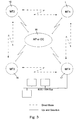
- Fig. 2 shows a typical message flow according to a preferred embodiment of the transmit power control according to the present invention.
- a central controller 18 with MAC-ID CC grants resources for the peer mobile terminals 1 and 15 to exchange transmit power control messages.
- those messages mainly carry a recommendation to the peer mobile terminal to increase/decrease its transmit power level by a certain value.
- source and destination identifiers i. e. the MAC-IDs MT1 and MT2, could be included so that the receiving mobile terminal can identify the link for which the recommendation is valid.
- the receiving mobile terminal can identify the link for which the recommendation is valid on basis of the time slot in which the recommendation is transmitted. If wanted, the transmit power level of the source mobile terminal and its desired receive power level can also be included.
- the grant of resources for the peer mobile terminals 1 and 15 by the central controller 18 is performed in step S0.
- the first mobile terminal 1 sends a message to the second mobile terminal 15 comprising the information not to adjust the transmit power level and optionally both MAC-IDs as well as its own transmit power level and its desired received power level.
- the first mobile terminal 1 transmits this message either using the maximum transmit power level or, in case that information about the link quality to the second mobile terminal 15 is known, an accordingly lower transmit power level.
- information about the radio link quality between all mobile terminals within a network can be taken from a topology map of the network which might be created by the central controller 18 during a network calibration process.
- the second mobile terminal 15 receives in step S2 this message, measures the received signal quality and replies to the first mobile terminal 1 by sending a message with the recommendation how to adjust the transmit power level and optionally both MAC-IDs as well as its own transmitter power level and its desired received power level.
- the recommendation to the first mobile terminal 1 how to adjust its transmit power level is preferably given as a certain value.
- the power level of the second mobile terminal 15 is set similar to the power level of the first mobile terminal 1.
- the first mobile terminal MT1 transmits the message with the recommendation how the second mobile terminal 15 should amend its power level by a certain value and optionally both MAC-IDs as well as its own transmit power level and its desired received power level.
- This message is transmitted to the second mobile terminal 15 with the transmit power level adjusted according to the recommendation of the second mobile terminal generated and transmitted in step S2.
- time slots for the direct mode transmit power control according to the present invention are granted in each frame, three frames are required to perform the transmit power control. During this time data can be transmitted using the power level identified during calibration.
- the second mobile terminal 15 transmits its message in step S2 using an appropriate transmit power level based on the received signal quality from the first mobile terminal 1 and the desired received signal quality thereof.
- step S3 might be redundant and therefore skipped.
- step S3 should be carried out to adjust the transmit power level of the second mobile terminal 15 accordingly.
- the transmit power level gets dynamically updated every time one of the peer mobile terminals finds it necessary. Therefore, each mobile terminal monitors the received signal quality and if a mobile terminal detects a deviation of a signal quality above a certain threshold, it notifies the peer mobile terminal to increase or decrease its transmit power level accordingly with a recommendation message according to the present invention.
- the threshold level is set to the wanted power level ⁇ 3 dB.
- a wireless network to be adapted according to the present invention is not necessarily, but preferably an IEEE 1394 based HIPERLAN type 2 network and a network device according to the present invention is preferably a mobile terminal to introduce a transmit power control for direct mode, but according to the present invention also transmit power control in-between the mobile terminal and the central controller/access point can be performed.
- a dedicated control channel can be used that conveys radio control protocol messages in direct mode.
Abstract
Description
- The present invention relates to a transmit power control for network devices in a wireless network, in particular to a transmit power control to be performed by network devices communicating in direct mode.
- A typical wireless network, such as the IEEE 1394 based HIPERLAN
type 2 broadband radio access network which specification is developed by ETSI is shown in Fig. 3. An access point orcentral controller 18 has an up- and downlink communication with severalmobile terminals mobile terminal 1 and the secondmobile terminal 15, the access point orcentral controller 18 is not involved in the communication. Such direct communications in-between two or more mobile terminals are called direct mode. An IEEE 1394 bus with connected network devices is exemplary shown only for the fourthmobile terminal 17. - For access point based wireless networks, i. e. for up- and downlink traffic, a transmit power control method is known according to which for uplink transmit power control the access point or central controller indicates its used transmit power and its desired received power levels. Based on these values and a measurement of the received signal strength each of the mobile terminals regulates its transmit power level to achieve a constant received power at the access point or
central controller 18. Thus, each of the first to fourthmobile terminals central controller 18 is often chosen so that allmobile terminals - On the other hand, no transmit power control is performed in direct mode, but the mobile terminals always use a maximum transmit power level to be able to establish the maximum number of direct communications. Therefore, all the advantages of transmit power control introduced for up- and downlink traffic disappear when direct connections are set up.
- Therefore, it is the object of the present invention to achieve the advantages of a transmit power control within a wireless network not only in up- and down-link mode, but also in direct mode.
- To solve this object a network device according to the present invention is defined in
independent claim 1 and a method to perform a transmit power control in-between two network devices of a wireless network according to the present invention is defined inindependent claim 6. Preferred embodiments thereof are respectively defined in the dependent claims. - A network device for a wireless network according to the present invention is characterized by means to adjust its transmit power on the basis of a recommendation for the transmit power regulation received from another network device and to generate a recommendation for the transmit power regulation for another network device on basis of the signal received from said other network device.
- Therefore, a network device according to the present invention enables a direct setting of the transmit power for a communication in-between peer network devices by exchanging messages in which recommendations for power control are carried.
- A method to perform a transmit power control in-between a first network device and a second network device of a wireless network according to the present invention therefore comprises the steps to transmit a message from the first network device to the second network device, measuring the received signal quality within the second network device and replying to the first network device by giving a recommendation to the first network device how to adjust its power level according to the measured received signal quality and the wanted received signal quality.
- Therefore, according to the inventive method, a receiving network device communicates a recommendation to the sending network device how to increase or decrease its transmit power level. This directly leads to an adaptation of the received signal strength to the signal strength desired by the receiving device. Therefore, the receiving device itself can adjust the strength of a signal incoming from another device to its optimal signal reception point.
- Preferably, a network device according to the present invention ensures that a maximum number of direct communications can be set up, since an adequate transmit power is initially used to reach the maximum number of mobile terminals.
- According to the present invention, preferably the maximum transmit power level or in case that information about the link quality in-between the peer network devices is known an accordingly lower transmit power level is used as appropriate power level. The information about the radio link quality between peer network devices can either be taken from a topology map of the network that shows the radio link quality between all network devices of the network or in case a message has recently been received from the network device to which the link quality is in question, it can be based on the received signal quality of this message.
- The adjustment of the transmit power of the second network device of the peer network devices is performed in the same way as the adjustment of the first network device, but the message giving a recommendation to the first network device how to adjust its power level will be used by the first network device to measure the received signal quality and to give a recommendation to the second network device how to adjust its power level.
- According to a further preferred embodiment of the inventive method, a transmit power control is performed in that an adjustment of the transmit power of a network device is performed every time said device receives a recommendation to change its transmit power level. Further preferably a recommendation to change the transmit power level is given to a transmitting device whenever the received power level exceeds a maximum deviation of the wanted received signals strength. Therewith, a dynamic update of the transmit power level is achieved which does not need an excitation from outside, e. g. from the central controller.
- Basically, every wireless network supporting direct mode can be adapted according to the present invention. Preferably the present invention is used within an IEEE 1394 based HIPERLAN
type 2 network. A network device according to the present invention can either be an access point/central controller or a mobile terminal. - The present invention and its numerous preferred embodiments will better be understood from the following detailed description of an exemplary embodiment thereof taken in conjunction of the accompanying drawings, in which
- Fig. 1 shows a network device according to the present invention;
- Fig. 2 shows the messaging in-between the central controller and two mobile terminals during setup of a direct mode communication and transmit power control; and
- Fig. 3 shows an exemplary wireless network.
-
- The mobile terminal shown in Fig. 1 is adapted to perform a direct mode transmit power control according to the present invention. The shown mobile terminal has one
antenna 1 which is connected to the movable terminal of a transmit/receiveselection switch 2 which fixed terminals are respectively connected to the transmitter and receiver signal path of the mobile terminal. In the receiver signal path areceiver 3 is directly connected to the respective fixed terminal of the transmit/receiveselection switch 2. Thisreceiver 3 produces a data and control signal input to acontroller 6 and also outputs a signal wherefrom a signalquality measurement unit 5 can determine the received signal strength which is output to thecontroller 6. For the transmitter signal path thecontroller 6 outputs a data and control signal to atransmitter 4 which modulates, up-converts and amplifies this signal to a given signal strength which is indicated to thetransmitter 4 by a control signal generated by thecontroller 6 and outputs the generated transmission signal to the respective fixed terminal of the transmit/receiveselection switch 2. Bi-directionally connected to the controller are auser interface 7 and amemory 8. Furtheron, thecontroller 6 is connected to a direct mode transmitpower control decoder 9 and a direct mode transmitpower control encoder 10. - The direct mode transmit
power control decoder 9 receives a respective control signal from the receiving path via thecontroller 6 and decodes it to supply the recommendation for a change in transmit power level to thecontroller 6. Based on this recommendation, thecontroller 6 determines the signal strength needed for transmission and supplies an appropriate signal strength control signal to thetransmitter 4 which then adapts its transmission power accordingly. - Based on the received signal strength determined by the signal
quality measurement unit 5 which is communicated to thecontroller 6 and the wanted received signal strength of thereceiver 3, which is known to thecontroller 6, a difference signal is generated within thecontroller 6 and supplied to the direct mode transmitpower control encoder 10. Said direct mode transmitpower control encoder 10 generates a control signal including a recommendation for power control and supplies it via thecontroller 6 as control signal to thetransmitter 4. Said control signal is transmitted via the transmit/receiveselection switch 2 and theantenna 1 to the peer mobile terminal adapting its transmission power accordingly in a similar way. - Fig. 2 shows a typical message flow according to a preferred embodiment of the transmit power control according to the present invention. After the connection setup in-between a first mobile terminal having the medium access control identifier, i. e MAC-ID, MT1 and a second
mobile terminal 15 having the MAC-ID MT2, acentral controller 18 with MAC-ID CC grants resources for the peermobile terminals mobile terminals central controller 18 is performed in step S0. - In the following step S1 the first
mobile terminal 1 sends a message to the secondmobile terminal 15 comprising the information not to adjust the transmit power level and optionally both MAC-IDs as well as its own transmit power level and its desired received power level. The firstmobile terminal 1 transmits this message either using the maximum transmit power level or, in case that information about the link quality to the secondmobile terminal 15 is known, an accordingly lower transmit power level. As stated above, such information about the radio link quality between all mobile terminals within a network can be taken from a topology map of the network which might be created by thecentral controller 18 during a network calibration process. - Thereafter, the second
mobile terminal 15 receives in step S2 this message, measures the received signal quality and replies to the firstmobile terminal 1 by sending a message with the recommendation how to adjust the transmit power level and optionally both MAC-IDs as well as its own transmitter power level and its desired received power level. The recommendation to the firstmobile terminal 1 how to adjust its transmit power level is preferably given as a certain value. The power level of the secondmobile terminal 15 is set similar to the power level of the firstmobile terminal 1. - In the last step S3 the first mobile terminal MT1 transmits the message with the recommendation how the second
mobile terminal 15 should amend its power level by a certain value and optionally both MAC-IDs as well as its own transmit power level and its desired received power level. This message is transmitted to the secondmobile terminal 15 with the transmit power level adjusted according to the recommendation of the second mobile terminal generated and transmitted in step S2. - If time slots for the direct mode transmit power control according to the present invention are granted in each frame, three frames are required to perform the transmit power control. During this time data can be transmitted using the power level identified during calibration.
- According to a further embodiment, the second
mobile terminal 15 transmits its message in step S2 using an appropriate transmit power level based on the received signal quality from the firstmobile terminal 1 and the desired received signal quality thereof. In this case, step S3 might be redundant and therefore skipped. However, if the firstmobile terminal 1 is located in a noisy environment and requires a higher signal strength from the secondmobile terminal 15, step S3 should be carried out to adjust the transmit power level of the secondmobile terminal 15 accordingly. - Preferably, the transmit power level gets dynamically updated every time one of the peer mobile terminals finds it necessary. Therefore, each mobile terminal monitors the received signal quality and if a mobile terminal detects a deviation of a signal quality above a certain threshold, it notifies the peer mobile terminal to increase or decrease its transmit power level accordingly with a recommendation message according to the present invention. Preferably, the threshold level is set to the wanted power level ± 3 dB.
- As mentioned above, a wireless network to be adapted according to the present invention is not necessarily, but preferably an IEEE 1394 based
HIPERLAN type 2 network and a network device according to the present invention is preferably a mobile terminal to introduce a transmit power control for direct mode, but according to the present invention also transmit power control in-between the mobile terminal and the central controller/access point can be performed. - To exchange the control messages which are generated according to the above exemplary embodiment by the direct mode transmit
power control encoder 10 and decoded by the direct mode transmitpower control decoder 9, a dedicated control channel can be used that conveys radio control protocol messages in direct mode.
Claims (12)
- Network device for a wireless network, characterized by means (5, 6, 9, 10) to adjust its transmit power on basis of a recommendation for the transmit power regulation received from another network device and to generate a recommendation for the transmit power regulation for another network device on basis of the transmission signal received from said other network device.
- Network device according to claim 1, characterized by a transmit power control decoder (9) that receives a transmit power control signal and decodes therefrom a recommendation signal indicating the amount to change the transmit power.
- Network device according to claim 1 or 2, characterized by a transmit power control encoder (10) that receives a transmit power deviation signal and encodes therefrom a transmit power control signal.
- Network device according to anyone of claims 1 to 3, characterized in that it is a mobile terminal or a central controller.
- Network device according to anyone of claims 1 to 4, characterized in that it is used in an IEEE 1394 based HIPERLAN type 2 network.
- Method to perform a transmit power control in-between a first network device (1) and a second network device (15) of a wireless network, characterized by the following steps:transmitting a message from the first network device(1) to the second network device (15);measuring the received signal quality of the signal carrying said message within the second network device, comparing it to the wanted received signal quality within the second network device (15), and based on this generating and transmitting a recommendation from the second network device (15) to the first network device (1) how to adjust its transmit power; andadjusting the transmission power within the first network device (1) on basis of the received recommendation how to adjust its transmit power.
- Method according to claim 6, characterized by the following additional steps:measuring the received signal quality of the signal carrying said recommendation within the first network device, comparing it to the wanted received signal quality within the first network device (1), and based on this generating and transmitting a recommendation from the first network device (1) to the second network device (15) how to adjust its transmit power; andadjusting the transmission power within the second network device (15) on basis of the received recommendation how to adjust its transmit power.
- Method according to claim 6 or 7, characterized in that the first transmitted message from the first network device (1) to the second network device (15) and/or the signal carrying the recommendation for the first network device how to adjust its transmit power has the maximum transmit power level of the first network device (1).
- Method according to claim 6 or 7, characterized in that the first transmitted message from the first network device (1) to the second network device (15) and/or the signal carrying the recommendation for the first network device how to adjust its transmit power has a transmit power level determined on basis of a topology map of the network indicating the quality of connectivity of all network devices within the network.
- Method according to claim 6 or 7, characterized in that the signal carrying the recommendation for the first network device how to adjust its transmit power has a transmit power level determined on basis of an information indicating the wanted received power level and the transmit power level of the first network device (1) which is transmitted with the first transmitted message from the first network device (1) to the second network device (15) and the received power level of said message at the second network device (15).
- Method according to anyone of claims 6 to 10, characterized in that a recommendation for a network device how to adjust its transmit power is always given from a peer network device in case the received power level exceeds a maximum deviation.
- Method according to anyone of claims 6 to 10, characterized in that it is performed within a network device according to anyone of claims 1 to 6.
Priority Applications (7)
| Application Number | Priority Date | Filing Date | Title |
|---|---|---|---|
| EP99112130A EP1063785B1 (en) | 1999-06-23 | 1999-06-23 | Transmit power control for network devices in a wireless network |
| DE69935131T DE69935131T2 (en) | 1999-06-23 | 1999-06-23 | Transmitter power control for network devices in a wireless network |
| US09/599,135 US6925286B1 (en) | 1999-06-23 | 2000-06-22 | Transmit power control for network devices in a wireless network |
| JP2000190066A JP2001044932A (en) | 1999-06-23 | 2000-06-23 | Network device and method for controlling transmission power |
| JP2012205777A JP5827194B2 (en) | 1999-06-23 | 2012-09-19 | Network device and transmission power control method |
| JP2014130616A JP2014171268A (en) | 1999-06-23 | 2014-06-25 | Network device and method for controlling transmission power |
| JP2014241673A JP2015084539A (en) | 1999-06-23 | 2014-11-28 | Network device and method for controlling transmission power |
Applications Claiming Priority (1)
| Application Number | Priority Date | Filing Date | Title |
|---|---|---|---|
| EP99112130A EP1063785B1 (en) | 1999-06-23 | 1999-06-23 | Transmit power control for network devices in a wireless network |
Publications (2)
| Publication Number | Publication Date |
|---|---|
| EP1063785A1 true EP1063785A1 (en) | 2000-12-27 |
| EP1063785B1 EP1063785B1 (en) | 2007-02-14 |
Family
ID=8238409
Family Applications (1)
| Application Number | Title | Priority Date | Filing Date |
|---|---|---|---|
| EP99112130A Expired - Lifetime EP1063785B1 (en) | 1999-06-23 | 1999-06-23 | Transmit power control for network devices in a wireless network |
Country Status (4)
| Country | Link |
|---|---|
| US (1) | US6925286B1 (en) |
| EP (1) | EP1063785B1 (en) |
| JP (4) | JP2001044932A (en) |
| DE (1) | DE69935131T2 (en) |
Cited By (14)
| Publication number | Priority date | Publication date | Assignee | Title |
|---|---|---|---|---|
| WO2003041297A1 (en) * | 2001-11-08 | 2003-05-15 | Telefonaktiebolaget Lm Ericsson Ab (Publ) | Method for link adaptation and transmit power control |
| DE10251314A1 (en) * | 2002-11-04 | 2004-05-19 | Advanced Micro Devices, Inc., Sunnyvale | Tuning based on broadcast statistics |
| WO2004077920A2 (en) * | 2003-03-07 | 2004-09-16 | Koninklijke Philips Electronics N.V. | Method and system for radio link establishment and maintenance with p2p communication in wireless communication |
| US7010313B2 (en) * | 2001-07-16 | 2006-03-07 | Motorola, Inc. | Communication system with controlled talk around mode |
| US7428423B2 (en) | 2001-07-16 | 2008-09-23 | Motorola, Inc. | Communication system with controlled talk around mode |
| US7653410B2 (en) | 2004-12-08 | 2010-01-26 | Sharp Kabushiki Kaisha | Radio communication device, radio communication system and measurement method capable of conducting appropriate transmit power control |
| US20100130126A1 (en) * | 2008-11-27 | 2010-05-27 | Sony Corporation | Communication device, communication method, program and communication system |
| WO2012106557A3 (en) * | 2011-02-03 | 2012-10-11 | Qualcomm Incorporated | Peer-to-peer/wan association control and resource coordination for mobile entities using aggregate neighborhood utility metrics |
| CN103096447A (en) * | 2011-11-01 | 2013-05-08 | 财团法人资讯工业策进会 | Mobile Apparatus, Base Station, Direct Communication System And Power Control Method Thereof |
| EP2224776A3 (en) * | 2009-02-25 | 2014-01-22 | LG Electronics Inc. | method of exchanging messages between devices in a wireless network, and devices for the same |
| CN105657808A (en) * | 2015-12-24 | 2016-06-08 | 杭州华三通信技术有限公司 | Radio frequency resource control method and device |
| EP2901774B1 (en) * | 2012-09-26 | 2017-01-18 | BlackBerry Limited | Transmit power adjustment for inter-device communication in wireless communication systems |
| US9591679B2 (en) | 2012-09-17 | 2017-03-07 | Blackberry Limited | Initiation of inter-device communication in wireless communication systems |
| US9826381B2 (en) | 2012-09-18 | 2017-11-21 | Blackberry Limited | Device handshake/discovery for inter-device communication in wireless communication systems |
Families Citing this family (32)
| Publication number | Priority date | Publication date | Assignee | Title |
|---|---|---|---|---|
| EP1063785B1 (en) * | 1999-06-23 | 2007-02-14 | Sony Deutschland GmbH | Transmit power control for network devices in a wireless network |
| DE69922797T2 (en) * | 1999-06-23 | 2005-10-13 | Sony International (Europe) Gmbh | Calibration procedure for wireless networks with direct traffic |
| EP2490489A3 (en) * | 2000-12-26 | 2012-10-31 | Fujitsu Limited | Error rate control apparatus |
| USRE47911E1 (en) | 2001-06-29 | 2020-03-17 | Koninklijke Philips N.V. | Noise margin information for power control and link adaptation in IEEE 802.11h WLAN |
| US7801544B2 (en) | 2001-06-29 | 2010-09-21 | Koninklijke Philips Electronics N.V. | Noise margin information for power control and link adaptation in IEEE 802.11h WLAN |
| US7245592B2 (en) * | 2001-07-09 | 2007-07-17 | Koninklijke Philips Electronics N.V. | Aligning 802.11e HCF and 802.11h TPC operations |
| EP1326386A1 (en) * | 2002-01-08 | 2003-07-09 | Canon Kabushiki Kaisha | Method and device for communication in a network |
| US8787988B2 (en) | 2003-01-29 | 2014-07-22 | Intellectual Ventures I Llc | Power management for wireless direct link |
| USRE43127E1 (en) | 2002-06-12 | 2012-01-24 | Intellectual Ventures I Llc | Event-based multichannel direct link |
| US7948951B2 (en) * | 2002-06-12 | 2011-05-24 | Xocyst Transfer Ag L.L.C. | Automatic peer discovery |
| US7933293B2 (en) * | 2002-06-12 | 2011-04-26 | Xocyst Transfer Ag L.L.C. | Link margin notification using return frame |
| US8050360B2 (en) | 2002-06-12 | 2011-11-01 | Intellectual Ventures I Llc | Direct link relay in a wireless network |
| US7545771B2 (en) * | 2003-01-29 | 2009-06-09 | Xocyst Transfer Ag L.L.C. | Independent direct link protocol |
| US20050130634A1 (en) * | 2003-10-31 | 2005-06-16 | Globespanvirata, Inc. | Location awareness in wireless networks |
| US20060116179A1 (en) * | 2004-11-30 | 2006-06-01 | Sarosh Vensuna | System and method for optimizing power consumption in a wireless device |
| JP4559207B2 (en) | 2004-12-21 | 2010-10-06 | 株式会社エヌ・ティ・ティ・ドコモ | Control device, mobile terminal, and communication control method |
| US8364185B2 (en) * | 2005-04-18 | 2013-01-29 | Samsung Electronics Co., Ltd. | Method and system for synchronizing a clock for an adjacent network to a clock for an overlay network |
| US8184655B2 (en) * | 2005-04-21 | 2012-05-22 | Interdigital Technology Corporation | Wireless communication method and WLAN for signaling deferral management messages |
| JP4470858B2 (en) * | 2005-10-28 | 2010-06-02 | 株式会社デンソー | Transceiver and transmitter / receiver adjustment system |
| WO2007054127A1 (en) * | 2005-11-10 | 2007-05-18 | Telefonaktiebolaget Lm Ericsson (Publ) | Arrangements in a mobile telecommunication network |
| US20070201540A1 (en) * | 2006-02-14 | 2007-08-30 | Berkman William H | Hybrid power line wireless communication network |
| US7733221B2 (en) * | 2006-06-30 | 2010-06-08 | Globalfoundries Inc. | Apparatus and method for wireless network parameter logging and reporting within a portable device having wireless communication functionality |
| US8483108B2 (en) * | 2006-07-24 | 2013-07-09 | Apple Inc. | Apparatus and methods for de-emphasis training on a point-to-point connection |
| CN101651481B (en) * | 2008-08-15 | 2013-04-17 | 工业和信息化部电信传输研究所 | Method for improving quality of broadcasting service in mobile communication network |
| US9014104B2 (en) * | 2008-11-04 | 2015-04-21 | Qualcomm Incorporated | Transmit power control based on receiver gain setting in a wireless communication network |
| US8401030B2 (en) * | 2008-12-08 | 2013-03-19 | Motorola Solutions, Inc. | Allocation of channels in a dedicated frequency spectrum on a secondary basis |
| US9161317B2 (en) * | 2010-11-08 | 2015-10-13 | Lg Electronics Inc. | Transmission power reporting method and apparatus |
| CN102710296A (en) * | 2011-03-28 | 2012-10-03 | 索尼爱立信移动通讯有限公司 | Working mode switching method, working mode switching module and terminal equipment |
| JP6154377B2 (en) * | 2012-07-27 | 2017-06-28 | 京セラ株式会社 | Mobile communication system, mobile communication method, radio base station, radio terminal, and processor |
| EP2950595B1 (en) * | 2013-01-24 | 2019-07-31 | LG Electronics Inc. | Method for controlling transmission power of discovery signal for device-to-device communication in wireless communication system and device for same |
| KR20160030970A (en) | 2013-07-10 | 2016-03-21 | 콘비다 와이어리스, 엘엘씨 | Context-aware proximity services |
| US20190246300A1 (en) * | 2018-02-05 | 2019-08-08 | Mediatek Inc. | Communication link checking method |
Citations (5)
| Publication number | Priority date | Publication date | Assignee | Title |
|---|---|---|---|---|
| US5003619A (en) * | 1989-01-31 | 1991-03-26 | Motorola, Inc. | Method and apparatus for adjusting the power of a transmitter |
| EP0548939A2 (en) * | 1991-12-26 | 1993-06-30 | Nec Corporation | Transmission power control system capable of keeping signal quality constant in mobile communication network |
| EP0579372A2 (en) * | 1992-07-03 | 1994-01-19 | NCR International, Inc. | Power control method in a wireless communication system |
| WO1998023044A2 (en) * | 1996-11-20 | 1998-05-28 | Qualcomm Incorporated | Method and apparatus for adjusting thresholds and measurements of received signals by anticipating power control commands yet to be executed |
| US5822682A (en) * | 1995-01-20 | 1998-10-13 | Nokia Telecommunications Oy | Communicating on a direct mode channel |
Family Cites Families (22)
| Publication number | Priority date | Publication date | Assignee | Title |
|---|---|---|---|---|
| JPS60165129A (en) * | 1984-02-07 | 1985-08-28 | Toyo Commun Equip Co Ltd | Extension connecting system controlling communication possible range |
| JPH04145733A (en) * | 1990-10-08 | 1992-05-19 | Nippon Telegr & Teleph Corp <Ntt> | In-zone communication system in mobile communication |
| JP3025712B2 (en) * | 1991-05-20 | 2000-03-27 | パイオニアコミュニケーションズ株式会社 | Cordless telephone communication between slave units |
| JPH05268141A (en) * | 1992-03-17 | 1993-10-15 | Clarion Co Ltd | Automatic adjustment device of transmission output for radio equipment and its method |
| KR100289630B1 (en) * | 1992-07-13 | 2001-05-02 | 리패치 | Wireless LAN output control method and device |
| JPH06334588A (en) * | 1993-05-25 | 1994-12-02 | Nec Corp | System and device for mobile radio station communication |
| JPH07212303A (en) * | 1994-01-12 | 1995-08-11 | Hitachi Ltd | Power control system |
| JPH07312610A (en) * | 1994-05-18 | 1995-11-28 | Oki Electric Ind Co Ltd | Radio communication control system |
| JPH08107382A (en) * | 1994-10-05 | 1996-04-23 | Tec Corp | Radio communication system |
| JPH09181722A (en) * | 1995-12-26 | 1997-07-11 | Kodo Tsushin Syst Kenkyusho:Kk | System for automatically generating network map using bgp routing information |
| KR980007105A (en) * | 1996-06-28 | 1998-03-30 | 김광호 | Method for controlling transmission power of mobile station |
| US6055429A (en) * | 1996-10-07 | 2000-04-25 | Lynch; Michael R. | Distributed wireless call processing system |
| JP3442593B2 (en) * | 1996-11-20 | 2003-09-02 | 株式会社東芝 | Network connection device and network connection method |
| DE19700303B4 (en) * | 1997-01-08 | 2005-11-03 | Deutsches Zentrum für Luft- und Raumfahrt e.V. | Radio transmission method for digital multimedia signals between subscriber stations in a local area network |
| US5983073A (en) * | 1997-04-04 | 1999-11-09 | Ditzik; Richard J. | Modular notebook and PDA computer systems for personal computing and wireless communications |
| GB9717868D0 (en) * | 1997-08-23 | 1997-10-29 | Philips Electronics Nv | Wireless network |
| JP3437070B2 (en) * | 1997-10-20 | 2003-08-18 | 富士通株式会社 | Subscriber wireless access system |
| US6298220B1 (en) * | 1998-01-15 | 2001-10-02 | Hughes Electronics Corporation | Power control system for communications channels |
| US6381230B1 (en) * | 1998-07-28 | 2002-04-30 | Qualcomm Incorporated | Method and system for providing personal base station communications |
| US6119010A (en) * | 1998-10-13 | 2000-09-12 | Motorola, Inc. | Method and apparatus for adjusting channel powers in a wireless communication system based on a predicted mobile location |
| US6363267B1 (en) * | 1999-04-07 | 2002-03-26 | Telefonaktiebolaget Lm Ericsson (Publ) | Mobile terminal decode failure procedure in a wireless local area network |
| EP1063785B1 (en) * | 1999-06-23 | 2007-02-14 | Sony Deutschland GmbH | Transmit power control for network devices in a wireless network |
-
1999
- 1999-06-23 EP EP99112130A patent/EP1063785B1/en not_active Expired - Lifetime
- 1999-06-23 DE DE69935131T patent/DE69935131T2/en not_active Expired - Lifetime
-
2000
- 2000-06-22 US US09/599,135 patent/US6925286B1/en not_active Expired - Lifetime
- 2000-06-23 JP JP2000190066A patent/JP2001044932A/en active Pending
-
2012
- 2012-09-19 JP JP2012205777A patent/JP5827194B2/en not_active Expired - Lifetime
-
2014
- 2014-06-25 JP JP2014130616A patent/JP2014171268A/en active Pending
- 2014-11-28 JP JP2014241673A patent/JP2015084539A/en active Pending
Patent Citations (5)
| Publication number | Priority date | Publication date | Assignee | Title |
|---|---|---|---|---|
| US5003619A (en) * | 1989-01-31 | 1991-03-26 | Motorola, Inc. | Method and apparatus for adjusting the power of a transmitter |
| EP0548939A2 (en) * | 1991-12-26 | 1993-06-30 | Nec Corporation | Transmission power control system capable of keeping signal quality constant in mobile communication network |
| EP0579372A2 (en) * | 1992-07-03 | 1994-01-19 | NCR International, Inc. | Power control method in a wireless communication system |
| US5822682A (en) * | 1995-01-20 | 1998-10-13 | Nokia Telecommunications Oy | Communicating on a direct mode channel |
| WO1998023044A2 (en) * | 1996-11-20 | 1998-05-28 | Qualcomm Incorporated | Method and apparatus for adjusting thresholds and measurements of received signals by anticipating power control commands yet to be executed |
Cited By (27)
| Publication number | Priority date | Publication date | Assignee | Title |
|---|---|---|---|---|
| US7010313B2 (en) * | 2001-07-16 | 2006-03-07 | Motorola, Inc. | Communication system with controlled talk around mode |
| US7428423B2 (en) | 2001-07-16 | 2008-09-23 | Motorola, Inc. | Communication system with controlled talk around mode |
| WO2003041297A1 (en) * | 2001-11-08 | 2003-05-15 | Telefonaktiebolaget Lm Ericsson Ab (Publ) | Method for link adaptation and transmit power control |
| CN1331312C (en) * | 2001-11-08 | 2007-08-08 | 艾利森电话股份有限公司 | Method for link adaptation and transmit power control |
| DE10251314A1 (en) * | 2002-11-04 | 2004-05-19 | Advanced Micro Devices, Inc., Sunnyvale | Tuning based on broadcast statistics |
| US7418054B2 (en) | 2002-11-04 | 2008-08-26 | Advanced Micro Devices, Inc. | Transmitter adjustment based on transmission statistics |
| WO2004077920A2 (en) * | 2003-03-07 | 2004-09-16 | Koninklijke Philips Electronics N.V. | Method and system for radio link establishment and maintenance with p2p communication in wireless communication |
| WO2004077920A3 (en) * | 2003-03-07 | 2005-04-28 | Koninkl Philips Electronics Nv | Method and system for radio link establishment and maintenance with p2p communication in wireless communication |
| US7653410B2 (en) | 2004-12-08 | 2010-01-26 | Sharp Kabushiki Kaisha | Radio communication device, radio communication system and measurement method capable of conducting appropriate transmit power control |
| US9325387B2 (en) | 2008-11-27 | 2016-04-26 | Sony Corporation | Communication device, communication method, program and communication system |
| US20100130126A1 (en) * | 2008-11-27 | 2010-05-27 | Sony Corporation | Communication device, communication method, program and communication system |
| US9960817B2 (en) | 2008-11-27 | 2018-05-01 | Sony Corporation | Communication device, communication method, program and communication system |
| EP2192810A3 (en) * | 2008-11-27 | 2011-06-15 | Sony Corporation | Communication device, communication method, program and communication system |
| US20150140931A1 (en) * | 2008-11-27 | 2015-05-21 | Sony Corporation | Communication device, communication method, program and communication system |
| RU2532618C2 (en) * | 2008-11-27 | 2014-11-10 | Сони Корпорейшн | Data transmission device, data transmission method and data transmission system |
| CN101753200B (en) * | 2008-11-27 | 2014-12-17 | 索尼株式会社 | Communication device, communication method, program and communication system |
| US8965278B2 (en) * | 2008-11-27 | 2015-02-24 | Sony Corporation | Communication device, communication method, program and communication system |
| EP2224776A3 (en) * | 2009-02-25 | 2014-01-22 | LG Electronics Inc. | method of exchanging messages between devices in a wireless network, and devices for the same |
| WO2012106557A3 (en) * | 2011-02-03 | 2012-10-11 | Qualcomm Incorporated | Peer-to-peer/wan association control and resource coordination for mobile entities using aggregate neighborhood utility metrics |
| CN103096447A (en) * | 2011-11-01 | 2013-05-08 | 财团法人资讯工业策进会 | Mobile Apparatus, Base Station, Direct Communication System And Power Control Method Thereof |
| CN103096447B (en) * | 2011-11-01 | 2016-07-20 | 财团法人资讯工业策进会 | Mobile device, base station, Direct Communication system and Poewr control method thereof |
| US9591679B2 (en) | 2012-09-17 | 2017-03-07 | Blackberry Limited | Initiation of inter-device communication in wireless communication systems |
| US9826381B2 (en) | 2012-09-18 | 2017-11-21 | Blackberry Limited | Device handshake/discovery for inter-device communication in wireless communication systems |
| EP2901774B1 (en) * | 2012-09-26 | 2017-01-18 | BlackBerry Limited | Transmit power adjustment for inter-device communication in wireless communication systems |
| US10154467B2 (en) | 2012-09-26 | 2018-12-11 | Blackberry Limited | Transmit power adjustment for inter-device communication in wireless communication systems |
| CN105657808A (en) * | 2015-12-24 | 2016-06-08 | 杭州华三通信技术有限公司 | Radio frequency resource control method and device |
| CN105657808B (en) * | 2015-12-24 | 2019-06-07 | 新华三技术有限公司 | A kind of radio frequency resource control method and device |
Also Published As
| Publication number | Publication date |
|---|---|
| EP1063785B1 (en) | 2007-02-14 |
| DE69935131D1 (en) | 2007-03-29 |
| JP2015084539A (en) | 2015-04-30 |
| DE69935131T2 (en) | 2007-11-22 |
| JP2001044932A (en) | 2001-02-16 |
| US6925286B1 (en) | 2005-08-02 |
| JP2014171268A (en) | 2014-09-18 |
| JP2013017229A (en) | 2013-01-24 |
| JP5827194B2 (en) | 2015-12-02 |
Similar Documents
| Publication | Publication Date | Title |
|---|---|---|
| US6925286B1 (en) | Transmit power control for network devices in a wireless network | |
| US7844276B2 (en) | Calibration procedure for wireless networks with direct mode traffic | |
| KR100343487B1 (en) | Access to Communication systems | |
| EP1231807B1 (en) | Controlling data transmission rate on the reserve link for each mobile station in a dedicated manner | |
| KR100973024B1 (en) | Power control for communications systems utilizing high speed shared channels | |
| US6728550B1 (en) | Coverage and cell extension in downlink power controlled wireless radio communication systems | |
| US20050059421A1 (en) | System, method, and apparatus for establishing headroom for a mobile station | |
| JP2007517475A (en) | Method and apparatus for providing individual power control information in a wireless local area network / wireless wide area network (WLAN / WWAN) | |
| US20070129094A1 (en) | Power control apparatus and method of time division duplex (TDD) telecommunication system | |
| CN101895978A (en) | The power control of point-to-multipoint physical channels | |
| KR101123191B1 (en) | A radio communication system, a radio station, and a method of transmitting data | |
| WO2005107101A1 (en) | Wireless communication system, base station apparatus, and transmission power control method | |
| US7574229B2 (en) | Output power control in multislot uplinks | |
| GB2354402A (en) | Radio transmitter | |
| US8200272B2 (en) | Apparatus and method for transmission power control of home base transceiver station (BTS) | |
| KR100729418B1 (en) | A method of controlling power | |
| KR20030059283A (en) | Allocation of shared channel data rates in a communication system | |
| AU713180B2 (en) | Data packet transmission method and apparatus for practicing the same | |
| KR101134756B1 (en) | Method, transmitter and receiver for selection of optimal transmit path in wideband high frequency wireless system with multiple transmit antenna | |
| JP4602456B2 (en) | Mobile communication system, base station and subscriber station | |
| KR20120069276A (en) | Method and apparatus for controlling transmission line category | |
| JP2003078483A (en) | Sending power control method and apparatus |
Legal Events
| Date | Code | Title | Description |
|---|---|---|---|
| PUAI | Public reference made under article 153(3) epc to a published international application that has entered the european phase |
Free format text: ORIGINAL CODE: 0009012 |
|
| AK | Designated contracting states |
Kind code of ref document: A1 Designated state(s): CH DE FI FR GB LI SE |
|
| AX | Request for extension of the european patent |
Free format text: AL;LT;LV;MK;RO;SI |
|
| 17P | Request for examination filed |
Effective date: 20010528 |
|
| AKX | Designation fees paid |
Free format text: CH DE FI FR GB LI SE |
|
| 17Q | First examination report despatched |
Effective date: 20050310 |
|
| RAP1 | Party data changed (applicant data changed or rights of an application transferred) |
Owner name: SONY DEUTSCHLAND GMBH |
|
| GRAP | Despatch of communication of intention to grant a patent |
Free format text: ORIGINAL CODE: EPIDOSNIGR1 |
|
| GRAS | Grant fee paid |
Free format text: ORIGINAL CODE: EPIDOSNIGR3 |
|
| GRAA | (expected) grant |
Free format text: ORIGINAL CODE: 0009210 |
|
| RBV | Designated contracting states (corrected) |
Designated state(s): DE FI FR GB SE |
|
| RIN1 | Information on inventor provided before grant (corrected) |
Inventor name: ENDERLEIN, JANOS,C/O SONY DEUTSCHLAND GMBH Inventor name: KRAIEM, BESMA,C/O SONY DEUTSCHLAND GMBH |
|
| AK | Designated contracting states |
Kind code of ref document: B1 Designated state(s): DE FI FR GB SE |
|
| PG25 | Lapsed in a contracting state [announced via postgrant information from national office to epo] |
Ref country code: FI Free format text: LAPSE BECAUSE OF FAILURE TO SUBMIT A TRANSLATION OF THE DESCRIPTION OR TO PAY THE FEE WITHIN THE PRESCRIBED TIME-LIMIT Effective date: 20070214 |
|
| REG | Reference to a national code |
Ref country code: GB Ref legal event code: FG4D |
|
| REF | Corresponds to: |
Ref document number: 69935131 Country of ref document: DE Date of ref document: 20070329 Kind code of ref document: P |
|
| PG25 | Lapsed in a contracting state [announced via postgrant information from national office to epo] |
Ref country code: SE Free format text: LAPSE BECAUSE OF FAILURE TO SUBMIT A TRANSLATION OF THE DESCRIPTION OR TO PAY THE FEE WITHIN THE PRESCRIBED TIME-LIMIT Effective date: 20070514 |
|
| RAP2 | Party data changed (patent owner data changed or rights of a patent transferred) |
Owner name: SONY DEUTSCHLAND GMBH |
|
| ET | Fr: translation filed | ||
| PLBE | No opposition filed within time limit |
Free format text: ORIGINAL CODE: 0009261 |
|
| STAA | Information on the status of an ep patent application or granted ep patent |
Free format text: STATUS: NO OPPOSITION FILED WITHIN TIME LIMIT |
|
| 26N | No opposition filed |
Effective date: 20071115 |
|
| REG | Reference to a national code |
Ref country code: FR Ref legal event code: PLFP Year of fee payment: 18 |
|
| REG | Reference to a national code |
Ref country code: FR Ref legal event code: PLFP Year of fee payment: 19 |
|
| PGFP | Annual fee paid to national office [announced via postgrant information from national office to epo] |
Ref country code: FR Payment date: 20170523 Year of fee payment: 19 Ref country code: DE Payment date: 20170522 Year of fee payment: 19 Ref country code: GB Payment date: 20170526 Year of fee payment: 19 |
|
| REG | Reference to a national code |
Ref country code: DE Ref legal event code: R119 Ref document number: 69935131 Country of ref document: DE |
|
| GBPC | Gb: european patent ceased through non-payment of renewal fee |
Effective date: 20180623 |
|
| PG25 | Lapsed in a contracting state [announced via postgrant information from national office to epo] |
Ref country code: FR Free format text: LAPSE BECAUSE OF NON-PAYMENT OF DUE FEES Effective date: 20180630 Ref country code: GB Free format text: LAPSE BECAUSE OF NON-PAYMENT OF DUE FEES Effective date: 20180623 Ref country code: DE Free format text: LAPSE BECAUSE OF NON-PAYMENT OF DUE FEES Effective date: 20190101 |