EP1069447B1 - Coated fiber strands having one or more heterogeneous regions and methods of making the same - Google Patents
Coated fiber strands having one or more heterogeneous regions and methods of making the same Download PDFInfo
- Publication number
- EP1069447B1 EP1069447B1 EP00303682A EP00303682A EP1069447B1 EP 1069447 B1 EP1069447 B1 EP 1069447B1 EP 00303682 A EP00303682 A EP 00303682A EP 00303682 A EP00303682 A EP 00303682A EP 1069447 B1 EP1069447 B1 EP 1069447B1
- Authority
- EP
- European Patent Office
- Prior art keywords
- coating layer
- strand
- fiber
- curable
- secondary coating
- Prior art date
- Legal status (The legal status is an assumption and is not a legal conclusion. Google has not performed a legal analysis and makes no representation as to the accuracy of the status listed.)
- Expired - Lifetime
Links
Images
Classifications
-
- C—CHEMISTRY; METALLURGY
- C03—GLASS; MINERAL OR SLAG WOOL
- C03C—CHEMICAL COMPOSITION OF GLASSES, GLAZES OR VITREOUS ENAMELS; SURFACE TREATMENT OF GLASS; SURFACE TREATMENT OF FIBRES OR FILAMENTS MADE FROM GLASS, MINERALS OR SLAGS; JOINING GLASS TO GLASS OR OTHER MATERIALS
- C03C25/00—Surface treatment of fibres or filaments made from glass, minerals or slags
- C03C25/10—Coating
- C03C25/48—Coating with two or more coatings having different compositions
- C03C25/50—Coatings containing organic materials only
-
- C—CHEMISTRY; METALLURGY
- C03—GLASS; MINERAL OR SLAG WOOL
- C03C—CHEMICAL COMPOSITION OF GLASSES, GLAZES OR VITREOUS ENAMELS; SURFACE TREATMENT OF GLASS; SURFACE TREATMENT OF FIBRES OR FILAMENTS MADE FROM GLASS, MINERALS OR SLAGS; JOINING GLASS TO GLASS OR OTHER MATERIALS
- C03C25/00—Surface treatment of fibres or filaments made from glass, minerals or slags
- C03C25/10—Coating
- C03C25/104—Coating to obtain optical fibres
- C03C25/1065—Multiple coatings
-
- C—CHEMISTRY; METALLURGY
- C03—GLASS; MINERAL OR SLAG WOOL
- C03C—CHEMICAL COMPOSITION OF GLASSES, GLAZES OR VITREOUS ENAMELS; SURFACE TREATMENT OF GLASS; SURFACE TREATMENT OF FIBRES OR FILAMENTS MADE FROM GLASS, MINERALS OR SLAGS; JOINING GLASS TO GLASS OR OTHER MATERIALS
- C03C25/00—Surface treatment of fibres or filaments made from glass, minerals or slags
- C03C25/10—Coating
- C03C25/465—Coatings containing composite materials
- C03C25/475—Coatings containing composite materials containing colouring agents
Description
- Coated fiber strands can be used in making a variety of products. For example, optical fibers typically comprise a fiber optic strand having one or more resin coating layers which protect the fiber from environmental conditions such as dust and moisture that can adversely effect its properties.
- Examples of multiple coating layers for optical fibers are disclosed in
U.S. Patent Nos. 4,480,898 ;4,474,830 ;4,851,165 ; and5,146,531 . - These coating layers often include a first, or primary, coating layer directly applied to the glass fiber, which acts as a "buffer" to cushion and protect the fiber, and a secondary coating layer. The secondary coating layer typically functions as a protective outer layer preventing damage to the fiber during processing and use.
- Because optical fiber coatings are typically clear, the resulting optical fiber is not colored. However, it is known to provide a colored coating and therefore a colored optical fiber. In this regard, a desired color is mixed into the prepolymer containing composition that forms the desired coating. This colored coating is then introduced as a substitute for the secondary coating or as an additional tertiary coating onto the fiber.
- While this technique has allowed for the "coloring" of fibers, it has introduced its own set of difficulties. For example, in processes which seek to cure both the primary and secondary coatings in a single curing step, the use of a colored secondary coating can adversely effect the cure of the inner or primary coatings and thus, lead to poor mechanical performance of the fiber.
- Moreover, from a practical standpoint, insofar as a manufacturer must maintain a separate inventory for each of the colored coatings, inventory management is more complicated. For example, at least twelve different colors are employed in the field of telephony. Accordingly, to provide color fibers for use in such environments, manufacturers would be required to maintain a separate inventory for each of the desired colored secondary coatings.
-
US-A-576905 discloses an optical fiber with a coating for the cladding of one or more plastic layers containing the fiber core and a color marking on or in the outer plastic layer, the color marking is covered by a further transparent or translucent layer. - The invention provides for a coated fiber strand according to
claim 1 and a method for making a coated fiber-strand according to claim 5. - The invention is based, at least in part, on the surprising discovery that one or more heterogeneous regions, e.g., coding stripes, can be introduced into or onto a coating layer on a fiber strand so as to provide for a desired functionality, e.g., coding of the fiber. Moreover, the region(s) can be introduced without adversely effecting subsequent processing steps used in making the fibers, e.g., curing of the coating layer(s).
- One aspect of the present invention relates to a coated fiber which includes a fiber strand, at least one coating layer which is directly or indirectly on the strand, and at least one heterogeneous region present in or on one or more of the coating layer(s). The invention involves the use of a primary coating layer and a secondary coating layer where the heterogeneous region(s) are in the secondary coating layer.
- While the heterogeneous region(s) preferably comprise a colored material useful in color coding of the fiber, the region can be used to provide a number of desired functionalities to the resulting fiber.
- Another aspect of the invention relates to a method for forming a coated fiber which includes introducing at least one coating layer onto a fiber strand such that the coating layer directly or indirectly covers at least a portion of the surface of the strand and introducing at least one heterogeneous region into or on one or more of the coating layer(s). The coated fiber can then be treated, e.g., cured so as to provide a desired product.
- Once again, the method involves introducing a primary coating layer and a secondary coating layer onto a strand. The region(s) are preferably introduced simultaneously with or subsequent to the secondary coating layer prior to curing of the coating layer.
-
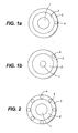
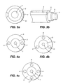
Figs. 1, 2 and4 illustrate coated fiber strands according to the present invention whileFigs. 1b ,3 and5 illustrate comparative examples of coated fiber strands withFigs. 1a, 1b, 2 ,3a, 3b, 4a, 4b, 4c ,and5 providing cross-sectional views of coated fibers having one or more heterogeneous regions; -
Figs. 6-9 illustrate suitable techniques for the simultaneous introduction of heterogeneous regions together with one or more coating layers onto a fiber strand. - The present invention relates to a fiber arrangement suitable for use in connection with optical fibers. The fiber arrangement according to the invention includes at least one heterogeneous region that is present in a coating layer which itself is directly or indirectly located on the surface of a fiber strand.
- By "heterogeneous region" it is meant that the region comprises a composition which differs from the composition of the surrounding layer. This heterogeneous region comprises a material that provides a desired functionality to the region.
- While one or more heterogeneous regions can extend around at least a portion of the periphery of the fiber strand, it is preferred that, particularly in connection with UV curing, the heterogeneous region(s) do not extend continuously around the circumference of the fiber. However, often curing techniques, e.g., electron beam, may allow for a more fully "covered" surface.
- It is further preferred that the heterogeneous regions extend longitudinally along the length of the strand defining, one or more heterogeneous "stripes" along at least a portion of the fiber strand. However, it is within the context of this invention that the regions can also be discontinuous along the length of the strand, defining, for example, a series of, e.g., "dots" and/or "dashes" along the length of the fiber strand.
- The fibers according to the invention include fiber strands that are recognized in the art, preferably a fiber strand suitable for forming an optical fiber, one or more coating layers on the fiber strand and one or more heterogeneous regions.
- The fiber strands can be produced for a variety of materials, including glass, polymers including plastics and the like. Moreover, coating materials suitable for use in the invention are dependent on the desired use for the coated fiber. For example, in the field of optical fibers, suitable primary and secondary coating material are well recognized in the field and include a variety of epoxy, urethane and acrylate-based resins.
- Specific techniques for introducing a primary and secondary coating layer onto an optical fiber strand are also known. See, for example, in
U.S. Patent 5,147,433 . Other examples of and techniques relating to multiple coating of optical fibers are discussed inU.S. Patent Nos. 4,480,898 ;4,474,830 ;4,851,165 ; and5,146,531 . These patents also illustrate suitable materials for both the primary and secondary coating layers. Accordingly, the general process of forming coated fibers suitable for use as optical fibers will not be described in detail here. - As discussed above, the present invention also includes one or more heterogeneous regions associated with a coating layer.
Figs. 1-5 illustrate examples of suitable arrangements. As can be seen fromFig. 1a , the heterogeneous region(s) can be located entirely within a coating layer whileFig. 1b illustrates a comparative example wherein the presence of a region is on the outside of a coating layer. In addition,Figs. 2 ,3a-3b ,4a-4c , and5 illustrate the use of multiple regions in connection with the fiber optic strand. In each case, afiber strand 1 coated with aprimary coating 2 andsecondary coating 3 including one ormore regions 4. - While these drawing figures illustrate the use of fibers having a two coating arrangement of primary and secondary coating layers, the present invention is not limited to such an arrangement.
- Moreover, where more than one region is employed, the regions can be either radially spaced within a coating layer from the glass fiber and/or circumferentially spaced around the periphery of the coated fiber. The approximate number and location of regions is dependent upon the nature of the ultimate end-use of the fiber. In the field of coated optical fibers, the use of one to four regions is preferred.
- While this specification will focus on the preferred use of one or more color-containing heterogeneous regions for coding of optical fibers, the region(s) can be used to provide a variety of different functions. For example, the region can comprise a conductive material to provide a conductive area within the fiber arrangement. In another embodiment, the stripe can comprise a material that would allow for bar coding of the strand. The region can also be used, e.g., to modify the properties of the fiber. For example, the region can comprise a material having a property, e.g., refractive index which differs from the coating(s) on the strand.
- Yet another use for the region would be as a sensor element, such as a curing sensor for the fiber. For example, the region can comprise a material capable of changing color during a subsequent processing step, e.g., UV curing. Such a material would be used as a sensor to determine when the coating layer(s) were subjected to a UV radiation level suitable for curing by way of a color change in the region.
- As discussed above, in the field of optical fibers, the region preferably comprises a colored material that would allow for coding of the fiber. To this end, the optical fibers according to the present invention preferably include one or more longitudinally extending heterogeneous regions so as to provide "stripes" on the fiber. The stripes can be of the same or different functionalities depending upon their intended purpose(s). Where coloring coding is the function, the stripes can be, for example, of the same or different colors.
- The composition of the heterogeneous region-forming material can vary greatly depending on its function. In this regard, where the region is a colored stripe, the material can be any material suitable to add color to a coating layer of an optical fiber without adversely affecting the properties of the coating layer(s).
- While not limited thereto, it is preferred that the stripe(s) be produced from a material that is compatible with the coating(s) on the fiber strand. The use of the UV curable materials as a secondary coating layer is well recognized in the field of forming optical fibers. Where UV curable formulations, e.g., UV curable prepolymers, are employed in forming a secondary coating layer, it is preferred that the stripe-forming composition also includes the same base prepolymer as the secondary coating layer.
- Where color stripes are desired, the stripe-forming compositions include one or more pigments or dyes. Such pigments and dyes can be premixed into the stripe forming composition. Suitable pigmented coating compositions for optical fibers are commercially available from Borden and DSM Desotech, Inc.
- A desired color scheme for the fiber can also be provided through the use of photo bleaching. In this regard, a coating material comprises a material which allows for photo bleachability, i.e., a change in the absorption properties of the material such that it absorbs at a different wave length subsequent to opposition to radiation, e.g., visible light.
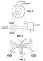
- Yet another technique for providing a variety of colors to the fiber involves the use of one or more color stripes selectively arranged to alter the perceived color of the stripe and/or the fiber strand. As illustrated in
Fig. 5 , combining ared stripe 4r and ayellow stripe 4y together onto a fiber is capable of providing a perceived orange stripe. In this regard, approximately twelve colors can be provided by various combinations of five colors, e.g., white, black, blue, red, and yellow.COLOR DESIRED STRIPES NEEDED Red Red Only Blue Blue Only Yellow Yellow Only Violet Red and Blue Brown Red and yellow and Green Orange Red and Yellow Green Blue and Yellow Black Blue and Green and Red White White Aqua White and Blue or Blue and Green Slate or Grey Black and White Rose White and Red - In forming color stripe(s), color brighteners may be added to enhance the brilliance or hue of the colors in addition to the desired pigments. Suitable examples of such materials include stilbenes, phenanthrenes and the like. Such materials include optical brighteners that function by the mechanism of absorbing UV light and fluorescing or phosphorescing at longer wavelengths near or in the visible spectrum.
- Another aspect of the invention involves methods for producing coated fiber strands and, in particular, an optical fiber including one or more heterogeneous regions. The method for making the fibers preferably involves introducing one or more heterogeneous region(s) within a coating layer which itself is directly or indirectly on the surface of the fiber strand.
- As discussed above, techniques for producing optical fibers and, in particular, optical fibers including one or more coating layers are known in the art. The present invention can be employed with such processes. For example, this invention is effectively employed with the recognized curing technique including ultra-violet (UV) curing of the coating layer(s).
-
Figs. 6 -9 illustrate examples of preferred techniques for introducing the heterogeneous region into the coated fiber strand. This invention may, however, be embodied in many different forms and should not be construed as limited to the embodiments set forth in the drawing figure; rather, these embodiments are provided so that this disclosure will be thorough and complete, and will fully convey the scope of the invention to those skilled in the art. Like numbers refer to like elements throughout. - In
Fig. 6 , a glass fiber drawn in the direction generally indicated byreference numeral 10 is coated with both a primarycoating layer application 12 and a secondarycoating layer application 13. In addition, a suitable heterogeneous region-forming material, e.g., a UV color coating liquid, is introduced at one ormore positions 14. - In this regard, most polymeric materials, e.g., UV curable prepolymer mixtures, do not typically mix during use, thus, the one or more heterogeneous region-forming compositions will flow onto the fiber strand to provide the desired stripe(s).
- An example of a suitable arrangement is illustrated in
Fig. 7 . InFig. 7 , the fiber is drawn in thedirection 10 withprimary coating feed 12 andsecondary coating feed 13 being introduced onto the strand. One or more of these heterogeneous region-formingmaterial streams 14 are introduced with the secondary coating layer. - Once again, where insofar as the primary layer, secondary layer and stripe-forming material is selected such that the primary and secondary coating layers do not mix, the desired stripes are formed on the fiber.
- Subsequent to stripe introduction the fiber is passed into a curing step (not shown) where the coating layers are subjected to UV radiation so as to cure the coating layers.
- Suitable apparatus elements for use in the present invention are recognized in the art. For example, any art recognized die can be effectively employed in the invention and as such are not described in detail here. However, for the sake of completeness, specific examples of suitable die include dual compact die and dual fixed die.
- The amount of heterogeneous region-forming material can be controlled through a variety of techniques including pressure reduction, and apparatus such as metering valves.
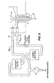
- A specific example of a suitable process for introducing stripes is illustrated by the pressure feed configuration in
Fig. 8 , the pressure of both the reservoir for the secondary coating and the reservoir for the stripe-forming material is applied from asingle gas source 20. Where pressure is maintained equal between the reservoir, the relative flow of the stripe-forming material is controlled by adjusting the ratio of resistance to flow between the feed lines of the secondary coating and the feed lines of the stripe-forming material:
where Rs is the resistance to flow in the feedline for the secondary coating and Rcc is the resistance in the feedline for the stripe forming material. - In addition, the location of the stripe relative to the coating layer can be adjusted depending upon the relationship of the strip material feed line to that of the secondary coating feedline. For example, in
Fig. 8 , if the striping material is introduced at point A, the stripe will be completely encapsulated within the secondary coating material. - While the present invention has been discussed in connection with formation of a preferred stripe which extends longitudinally along the length of the optical fiber, additional modifications and optimizations can be employed.
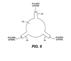
- For example, one or more pulse stripes can be introduced circumferentially around the fiber to produce random "lumps" of stripe-forming material on the fiber. Such a technique can be produced by the arrangement schematically illustrated be
Fig. 9 where the pulses can be generated, for example, by a pulse pressure delivery system - Many modifications and other embodiments of the invention will come to mind to one skilled in the art to which this invention pertains having the benefit of the teachings presented in the foregoing descriptions and the associated drawings. Therefore, it is to be understood that the invention is not to be limited to the specific embodiments disclosed and that modifications and other embodiments are intended to be included within the scope of the appended claims. Although specific terms are employed herein, they are used in a generic and descriptive sense only and not for purposes of limitation.
Claims (10)
- A coated fiber strand comprising:(a) a fiber strand (1);(b) a primary coating layer (2) on the fiber strand (1) such that the primary coating layer (2) directly or indirectly covers at least a portion of the fiber strand (1);(c) a single secondary UV curable coating layer (3) applied from a single reservoir on the fiber strand (1) such that the secondary coating layer (3) directly or indirectly covers at least a portion of the primary coating layer (2); and(d) one or more UV curable coding regions (4) made of a composition which differs from the composition of the secondary coating layer and which are entirely embedded within the secondary coating layer (3) such that the secondary coating layer (3) alone contacts the UV curable coding regions (4) on all sides.
- A coated fiber strand according to claim 1 wherein the one or more UV curable coding regions (4) extend longitudinally along at least a portion of the fiber strand (1).
- The coated fiber strand according to claim 1 wherein the one or more UV curable coding regions (4) is colored.
- The coated fiber strand according to claim 1 wherein the one or more UV curable coding regions (4) each have a different color.
- A method for making a coated fiber strand comprises:(a) providing a fiber strand (1);(b) introducing a primary coating layer (2) onto the fiber strand (1) such that the primary coating layer (2) directly or indirectly covers at least a portion of the surface of the fiber strand (1); and(c) introducing a single secondary UV curable coating layer (3) applied from a single reservoir and one or more UV curable coding regions (4) made of a composition which differs from the composition of the secondary coating layer such that the secondary coating layer (3) directly or indirectly covers at least a portion of the surface of the primary layer (2) and the one or more UV curable coding regions (4) are entirely embedded within the secondary coating layer (3) such that the secondary coating layer (3) alone contacts the UV curable coding regions (4) on all sides.
- The method according to claim 5 further comprising:(d) curing the primary coating layer (2);(e) curing the secondary coating layer (3); and(f) curing the one or more UV curable coding region (4).
- The method according to claim 6 wherein steps (d), (e), and (f) are performed simultaneously.
- The method according to claim 5 wherein the at least one UV curable coding regions (4) is colored.
- A method according to claim 5,
wherein step (a) comprises(a1) passing a fiber optic strand through a primary coating die;(a2) applying a primary coating layer (2) about and along the length of the strand during the drawing of the fiber optic strand;wherein step (b) comprises(b 1) passing the coated strand through a secondary coating die;(b2) applying a secondary coating layer (3) about and along the length of the coated strand during the drawing of the fiber optic strand; andwherein step (c) comprises(c1) applying one or more UV curable coding regions (4) into the strand during application of the secondary coating and during the drawing of the fiber optic strand, such that the one or more coding regions (4) are entirely embedded within the secondary coating layer (3) such that the secondary coating layer (3) alone contacts the UV curable coding regions (4) on all sides. - The method according to claim 5, wherein the primary coating layer (2) and secondary coating layer (3) are applied by a single coating applicator.
Applications Claiming Priority (2)
| Application Number | Priority Date | Filing Date | Title |
|---|---|---|---|
| US09/307,306 US6317553B1 (en) | 1999-05-07 | 1999-05-07 | Coated fiber strands having one or more heterogeneous regions and methods of making the same |
| US307306 | 1999-05-07 |
Publications (3)
| Publication Number | Publication Date |
|---|---|
| EP1069447A2 EP1069447A2 (en) | 2001-01-17 |
| EP1069447A3 EP1069447A3 (en) | 2002-02-06 |
| EP1069447B1 true EP1069447B1 (en) | 2011-07-06 |
Family
ID=23189150
Family Applications (1)
| Application Number | Title | Priority Date | Filing Date |
|---|---|---|---|
| EP00303682A Expired - Lifetime EP1069447B1 (en) | 1999-05-07 | 2000-05-03 | Coated fiber strands having one or more heterogeneous regions and methods of making the same |
Country Status (3)
| Country | Link |
|---|---|
| US (2) | US6317553B1 (en) |
| EP (1) | EP1069447B1 (en) |
| JP (2) | JP2000351654A (en) |
Families Citing this family (36)
| Publication number | Priority date | Publication date | Assignee | Title |
|---|---|---|---|---|
| US6602601B2 (en) * | 2000-12-22 | 2003-08-05 | Corning Incorporated | Optical fiber coating compositions |
| KR20030085553A (en) * | 2001-03-16 | 2003-11-05 | 스미토모덴키고교가부시키가이샤 | Optical fiber and method of manufacturing the optical fiber |
| US6733186B2 (en) * | 2001-09-27 | 2004-05-11 | Siemens Information & Communication Networks, Inc. | Optical connection verification apparatus and method |
| US6904212B2 (en) * | 2001-12-11 | 2005-06-07 | Tyco Telecommunications (Us) Inc. | System and method for coloring an optical fiber |
| US6859600B2 (en) * | 2002-05-30 | 2005-02-22 | Alcatel | Coated optical fiber and optical fiber ribbon and method for the fabrication thereof |
| US7072554B2 (en) * | 2002-08-09 | 2006-07-04 | Fujikura Ltd. | Optical fiber and optical fiber cable using the same |
| US7400808B2 (en) * | 2003-01-10 | 2008-07-15 | The Furukawa Electric Co., Ltd. | Optical fiber, light amplifier, and light source |
| US7591904B2 (en) * | 2004-09-22 | 2009-09-22 | Fueukawa Electric North America, Inc. | System and method for manufacturing color-coated optical fiber |
| US20100140851A1 (en) * | 2007-03-20 | 2010-06-10 | Jin Yu-Syuan | In-Mould Coating Method |
| WO2011063214A1 (en) | 2009-11-20 | 2011-05-26 | Corning Incorporated | Illumination system with side - emitting optical photonic fibre and manufacturing method thereof |
| US8351749B2 (en) * | 2009-12-17 | 2013-01-08 | Ofs Fitel, Llc | Optical fiber coating with a color concentrate having slickness additive |
| CN103221862B (en) | 2010-10-28 | 2016-10-26 | 康宁光缆系统有限责任公司 | There is extruded type close to the fiber optic cables of feature and for the method manufacturing fiber optic cables |
| US9201208B2 (en) | 2011-10-27 | 2015-12-01 | Corning Cable Systems Llc | Cable having core, jacket and polymeric jacket access features located in the jacket |
| US8620123B2 (en) * | 2012-02-13 | 2013-12-31 | Corning Cable Systems Llc | Visual tracer system for fiber optic cable |
| CN102584000A (en) * | 2012-02-28 | 2012-07-18 | 南京烽火藤仓光通信有限公司 | Optical fiber manufacture method of optical fiber belt capable of being stripped by means of windowing |
| US8768128B1 (en) | 2013-01-22 | 2014-07-01 | Ofs Fitel, Llc | Color coded optical fibers |
| US9517971B2 (en) | 2013-02-19 | 2016-12-13 | Teldor Cables & Systems Ltd. | Dual-color coating of optical fibers with UV curable inks |
| US9429731B2 (en) | 2013-08-12 | 2016-08-30 | Corning Optical Communications LLC | Optical fiber cable assembly comprising optical tracer fiber |
| RU2602594C2 (en) * | 2013-08-15 | 2016-11-20 | Общество с ограниченной ответственностью "Сферастек" | Glass |
| RU2602328C2 (en) * | 2013-08-15 | 2016-11-20 | Общество с ограниченной ответственностью "Сферастек" | Glass microsphere |
| US10379309B2 (en) | 2014-11-18 | 2019-08-13 | Corning Optical Communications LLC | Traceable optical fiber cable and filtered viewing device for enhanced traceability |
| US9304278B1 (en) * | 2015-03-31 | 2016-04-05 | Corning Optical Communications LLC | Traceable cable with side-emitting optical fiber and method of forming the same |
| US10228526B2 (en) | 2015-03-31 | 2019-03-12 | Corning Optical Communications LLC | Traceable cable with side-emitting optical fiber and method of forming the same |
| US10101553B2 (en) | 2015-05-20 | 2018-10-16 | Corning Optical Communications LLC | Traceable cable with side-emitting optical fiber and method of forming the same |
| WO2017015084A1 (en) | 2015-07-17 | 2017-01-26 | Corning Optical Communications LLC | Systems and methods for traceable cables |
| WO2017015085A1 (en) | 2015-07-17 | 2017-01-26 | Corning Optical Communications LLC | Systems and methods for tracing cables and cables for such systems and methods |
| US10101545B2 (en) | 2015-10-30 | 2018-10-16 | Corning Optical Communications LLC | Traceable cable assembly and connector |
| JP6627486B2 (en) * | 2015-12-18 | 2020-01-08 | 日立金属株式会社 | Optical fiber cable and optical fiber cable identification method |
| CN109154701A (en) | 2016-04-08 | 2019-01-04 | 康宁研究与开发公司 | With light structures and for carrying the traceable fiber optical cable assembly from the tracking optical fiber of the received light of light originating device |
| US10107983B2 (en) | 2016-04-29 | 2018-10-23 | Corning Optical Communications LLC | Preferential mode coupling for enhanced traceable patch cord performance |
| US10222560B2 (en) | 2016-12-21 | 2019-03-05 | Corning Research & Development Corporation | Traceable fiber optic cable assembly with fiber guide and tracing optical fibers for carrying light received from a light launch device |
| US10234614B2 (en) | 2017-01-20 | 2019-03-19 | Corning Research & Development Corporation | Light source assemblies and systems and methods with mode homogenization |
| US10539747B2 (en) | 2017-12-05 | 2020-01-21 | Corning Research & Development Corporation | Bend induced light scattering fiber and cable assemblies and method of making |
| US10539758B2 (en) | 2017-12-05 | 2020-01-21 | Corning Research & Development Corporation | Traceable fiber optic cable assembly with indication of polarity |
| JP7078459B2 (en) * | 2018-05-31 | 2022-05-31 | 三菱電線工業株式会社 | Optical fiber manufacturing and processing equipment |
| JP7474391B1 (en) | 2023-11-30 | 2024-04-24 | Swcc株式会社 | Method for manufacturing optical fiber ribbon |
Family Cites Families (20)
| Publication number | Priority date | Publication date | Assignee | Title |
|---|---|---|---|---|
| US576905A (en) | 1897-02-09 | Alfred j | ||
| JPS5626708U (en) * | 1979-08-06 | 1981-03-12 | ||
| US4480898A (en) | 1982-12-29 | 1984-11-06 | At&T Bell Laboratories | Fibers with multiple coatings |
| US4474830A (en) | 1982-12-29 | 1984-10-02 | At&T Bell Laboratories | Multiple coating of fibers |
| US4629285A (en) * | 1984-02-21 | 1986-12-16 | Fusion Uv Curing Systems Corporation | Color coded optical fiber waveguides and method for coloring same |
| FR2613981B1 (en) * | 1987-04-15 | 1989-10-13 | Swisscab E A Schoen Sa | METHOD AND HEAD FOR EXTRUDING PROFILES IN SYNTHETIC MATERIAL HAVING COLORED STRIPS |
| US4851165A (en) | 1987-09-02 | 1989-07-25 | American Telephone And Telegraph Company At&T Bell Laboratories | Methods of and apparatus for coating optical fiber |
| CA1321671C (en) | 1989-05-11 | 1993-08-24 | Paul J. Shustack | Ultraviolet radiation-curable coatings for optical fibers and optical fibers coated therewith |
| US5147433A (en) | 1990-02-15 | 1992-09-15 | At&T Bell Laboratories | Methods of making coated optical fiber |
| DE4209830A1 (en) * | 1992-03-26 | 1993-09-30 | Rheydt Kabelwerk Ag | Optical fiber with additional color marking |
| FR2694417B1 (en) * | 1992-07-31 | 1994-09-16 | Alcatel Cable | Ribbon of individualized optical fibers. |
| US5259060A (en) * | 1992-08-11 | 1993-11-02 | Corning Incorporated | Coated optical fibers and method |
| IT1271484B (en) * | 1993-10-12 | 1997-05-28 | Alcatel Cavi Spa | MODULAR OPTICAL FIBER TAPE, SEPARABLE INTO A PLURALITY OF TAPES OR MODULES, PROCEDURE FOR MANUFACTURING SUCH TAPE AND OPTICAL CABLE USING THE SAME |
| DE4407406A1 (en) * | 1993-12-23 | 1995-06-29 | Rheydt Kabelwerk Ag | Optical fiber with a color coding |
| DE4438090A1 (en) * | 1994-10-25 | 1996-05-02 | Siemens Ag | Coating and integrated durable marking of electrical and optical cables |
| US5837750A (en) * | 1995-03-13 | 1998-11-17 | Dsm N.V. | Radiation curable optical fiber coating composition |
| DE19525816A1 (en) * | 1995-07-15 | 1997-01-16 | Alcatel Kabel Ag | Optical fiber with color coding |
| JPH0980275A (en) * | 1995-09-11 | 1997-03-28 | Fujikura Ltd | Structure of coated optical fiber |
| US5903695A (en) * | 1996-03-27 | 1999-05-11 | Lumenyte International Corp. | Linear light form with light diverting layer |
| US6301415B1 (en) * | 1997-08-14 | 2001-10-09 | Dsm N.V | Optical glass fiber ribbon assemblies, matrix forming compositions radiation-curable compositions |
-
1999
- 1999-05-07 US US09/307,306 patent/US6317553B1/en not_active Expired - Lifetime
-
2000
- 2000-05-02 JP JP2000133424A patent/JP2000351654A/en active Pending
- 2000-05-03 EP EP00303682A patent/EP1069447B1/en not_active Expired - Lifetime
-
2001
- 2001-09-12 US US09/952,805 patent/US6649215B2/en not_active Expired - Lifetime
-
2007
- 2007-04-25 JP JP2007115033A patent/JP4685829B2/en not_active Expired - Lifetime
Also Published As
| Publication number | Publication date |
|---|---|
| US20020034584A1 (en) | 2002-03-21 |
| JP2007246394A (en) | 2007-09-27 |
| EP1069447A3 (en) | 2002-02-06 |
| JP2000351654A (en) | 2000-12-19 |
| US6649215B2 (en) | 2003-11-18 |
| JP4685829B2 (en) | 2011-05-18 |
| EP1069447A2 (en) | 2001-01-17 |
| US6317553B1 (en) | 2001-11-13 |
Similar Documents
| Publication | Publication Date | Title |
|---|---|---|
| EP1069447B1 (en) | Coated fiber strands having one or more heterogeneous regions and methods of making the same | |
| LT4044B (en) | Optical fibre with a colour marking | |
| US6381390B1 (en) | Color-coded optical fiber ribbon and die for making the same | |
| US5377292A (en) | Optical fiber with additional color markings | |
| US6678449B2 (en) | Visibly distinguishable colored optical fiber ribbons | |
| AU657867B2 (en) | Coated optical fibers and method | |
| EP1065546B1 (en) | Incorporation of UV transparent perlescent pigments to UV curable optical fiber materials | |
| US8358894B2 (en) | Optical cable with identifiable optical fibers | |
| US6026207A (en) | Black appearing color coating for optical fiber and method using same | |
| EP0411310B1 (en) | Coated optical fiber | |
| US8452146B2 (en) | Process for manufacturing an optical fiber and an optical fiber so obtained | |
| KR100490610B1 (en) | Process for producing colored shaped article from curable resin, colored shaped article produced from curable resin, and shaping apparatus | |
| CA2227311A1 (en) | Color coded optical fiber | |
| EP2757080A2 (en) | Color coded optical fibers | |
| JP2000009971A (en) | Color coding of optical fiber | |
| JP2001183558A (en) | Optical fiber and method of manufacturing optical fiber | |
| DE19512511C2 (en) | Process for the continuous production of optical waveguide ribbons | |
| JPH0792360A (en) | Coated optical fiber ribbon | |
| JP2002362946A (en) | Colored and coated optical fiber and optical fiber unit |
Legal Events
| Date | Code | Title | Description |
|---|---|---|---|
| PUAI | Public reference made under article 153(3) epc to a published international application that has entered the european phase |
Free format text: ORIGINAL CODE: 0009012 |
|
| AK | Designated contracting states |
Kind code of ref document: A2 Designated state(s): AT BE CH CY DE DK ES FI FR GB GR IE IT LI LU MC NL PT SE Kind code of ref document: A2 Designated state(s): DE FR GB |
|
| AX | Request for extension of the european patent |
Free format text: AL;LT;LV;MK;RO;SI |
|
| PUAL | Search report despatched |
Free format text: ORIGINAL CODE: 0009013 |
|
| AK | Designated contracting states |
Kind code of ref document: A3 Designated state(s): AT BE CH CY DE DK ES FI FR GB GR IE IT LI LU MC NL PT SE |
|
| AX | Request for extension of the european patent |
Free format text: AL;LT;LV;MK;RO;SI |
|
| RIC1 | Information provided on ipc code assigned before grant |
Free format text: 7G 02B 6/44 A, 7C 03C 25/10 B |
|
| 17P | Request for examination filed |
Effective date: 20020412 |
|
| AKX | Designation fees paid |
Free format text: DE FR GB |
|
| 17Q | First examination report despatched |
Effective date: 20041116 |
|
| 17Q | First examination report despatched |
Effective date: 20041116 |
|
| RAP3 | Party data changed (applicant data changed or rights of an application transferred) |
Owner name: LUCENT TECHNOLOGIES INC. |
|
| GRAP | Despatch of communication of intention to grant a patent |
Free format text: ORIGINAL CODE: EPIDOSNIGR1 |
|
| GRAS | Grant fee paid |
Free format text: ORIGINAL CODE: EPIDOSNIGR3 |
|
| GRAA | (expected) grant |
Free format text: ORIGINAL CODE: 0009210 |
|
| AK | Designated contracting states |
Kind code of ref document: B1 Designated state(s): DE FR GB |
|
| REG | Reference to a national code |
Ref country code: GB Ref legal event code: FG4D |
|
| REG | Reference to a national code |
Ref country code: DE Ref legal event code: R096 Ref document number: 60046168 Country of ref document: DE Effective date: 20110825 |
|
| PLBE | No opposition filed within time limit |
Free format text: ORIGINAL CODE: 0009261 |
|
| STAA | Information on the status of an ep patent application or granted ep patent |
Free format text: STATUS: NO OPPOSITION FILED WITHIN TIME LIMIT |
|
| 26N | No opposition filed |
Effective date: 20120411 |
|
| REG | Reference to a national code |
Ref country code: DE Ref legal event code: R097 Ref document number: 60046168 Country of ref document: DE Effective date: 20120411 |
|
| PGFP | Annual fee paid to national office [announced via postgrant information from national office to epo] |
Ref country code: GB Payment date: 20140527 Year of fee payment: 15 |
|
| PGFP | Annual fee paid to national office [announced via postgrant information from national office to epo] |
Ref country code: FR Payment date: 20140519 Year of fee payment: 15 Ref country code: DE Payment date: 20140529 Year of fee payment: 15 |
|
| REG | Reference to a national code |
Ref country code: DE Ref legal event code: R119 Ref document number: 60046168 Country of ref document: DE |
|
| GBPC | Gb: european patent ceased through non-payment of renewal fee |
Effective date: 20150503 |
|
| REG | Reference to a national code |
Ref country code: FR Ref legal event code: ST Effective date: 20160129 |
|
| PG25 | Lapsed in a contracting state [announced via postgrant information from national office to epo] |
Ref country code: GB Free format text: LAPSE BECAUSE OF NON-PAYMENT OF DUE FEES Effective date: 20150503 Ref country code: DE Free format text: LAPSE BECAUSE OF NON-PAYMENT OF DUE FEES Effective date: 20151201 |
|
| PG25 | Lapsed in a contracting state [announced via postgrant information from national office to epo] |
Ref country code: FR Free format text: LAPSE BECAUSE OF NON-PAYMENT OF DUE FEES Effective date: 20150601 |