EP1072842A2 - Power tools having lighting devices - Google Patents
Power tools having lighting devices Download PDFInfo
- Publication number
- EP1072842A2 EP1072842A2 EP00116429A EP00116429A EP1072842A2 EP 1072842 A2 EP1072842 A2 EP 1072842A2 EP 00116429 A EP00116429 A EP 00116429A EP 00116429 A EP00116429 A EP 00116429A EP 1072842 A2 EP1072842 A2 EP 1072842A2
- Authority
- EP
- European Patent Office
- Prior art keywords
- circuit
- light emitters
- previous
- lighting
- electric
- Prior art date
- Legal status (The legal status is an assumption and is not a legal conclusion. Google has not performed a legal analysis and makes no representation as to the accuracy of the status listed.)
- Granted
Links
Images

Classifications
-
- B—PERFORMING OPERATIONS; TRANSPORTING
- B25—HAND TOOLS; PORTABLE POWER-DRIVEN TOOLS; MANIPULATORS
- B25F—COMBINATION OR MULTI-PURPOSE TOOLS NOT OTHERWISE PROVIDED FOR; DETAILS OR COMPONENTS OF PORTABLE POWER-DRIVEN TOOLS NOT PARTICULARLY RELATED TO THE OPERATIONS PERFORMED AND NOT OTHERWISE PROVIDED FOR
- B25F5/00—Details or components of portable power-driven tools not particularly related to the operations performed and not otherwise provided for
- B25F5/02—Construction of casings, bodies or handles
- B25F5/021—Construction of casings, bodies or handles with guiding devices
-
- F—MECHANICAL ENGINEERING; LIGHTING; HEATING; WEAPONS; BLASTING
- F21—LIGHTING
- F21V—FUNCTIONAL FEATURES OR DETAILS OF LIGHTING DEVICES OR SYSTEMS THEREOF; STRUCTURAL COMBINATIONS OF LIGHTING DEVICES WITH OTHER ARTICLES, NOT OTHERWISE PROVIDED FOR
- F21V23/00—Arrangement of electric circuit elements in or on lighting devices
- F21V23/04—Arrangement of electric circuit elements in or on lighting devices the elements being switches
- F21V23/0442—Arrangement of electric circuit elements in or on lighting devices the elements being switches activated by means of a sensor, e.g. motion or photodetectors
-
- Y—GENERAL TAGGING OF NEW TECHNOLOGICAL DEVELOPMENTS; GENERAL TAGGING OF CROSS-SECTIONAL TECHNOLOGIES SPANNING OVER SEVERAL SECTIONS OF THE IPC; TECHNICAL SUBJECTS COVERED BY FORMER USPC CROSS-REFERENCE ART COLLECTIONS [XRACs] AND DIGESTS
- Y10—TECHNICAL SUBJECTS COVERED BY FORMER USPC
- Y10S—TECHNICAL SUBJECTS COVERED BY FORMER USPC CROSS-REFERENCE ART COLLECTIONS [XRACs] AND DIGESTS
- Y10S362/00—Illumination
- Y10S362/802—Position or condition responsive switch
-
- Y—GENERAL TAGGING OF NEW TECHNOLOGICAL DEVELOPMENTS; GENERAL TAGGING OF CROSS-SECTIONAL TECHNOLOGIES SPANNING OVER SEVERAL SECTIONS OF THE IPC; TECHNICAL SUBJECTS COVERED BY FORMER USPC CROSS-REFERENCE ART COLLECTIONS [XRACs] AND DIGESTS
- Y10—TECHNICAL SUBJECTS COVERED BY FORMER USPC
- Y10T—TECHNICAL SUBJECTS COVERED BY FORMER US CLASSIFICATION
- Y10T408/00—Cutting by use of rotating axially moving tool
- Y10T408/21—Cutting by use of rotating axially moving tool with signal, indicator, illuminator or optical means
-
- Y—GENERAL TAGGING OF NEW TECHNOLOGICAL DEVELOPMENTS; GENERAL TAGGING OF CROSS-SECTIONAL TECHNOLOGIES SPANNING OVER SEVERAL SECTIONS OF THE IPC; TECHNICAL SUBJECTS COVERED BY FORMER USPC CROSS-REFERENCE ART COLLECTIONS [XRACs] AND DIGESTS
- Y10—TECHNICAL SUBJECTS COVERED BY FORMER USPC
- Y10T—TECHNICAL SUBJECTS COVERED BY FORMER US CLASSIFICATION
- Y10T83/00—Cutting
- Y10T83/828—With illuminating or viewing means for work
Definitions
- the present invention relates to electric tools having lighting devices, and in particular, to portable electric drills and screwdrivers having lighting devices. Such lighting devices permit the operator to illuminate the working in accordance ambient light levels.
- the present invention also relates to lighting devices that can be utilized, for example, in machine tools.
- German Patent No. 3831344 discloses a portable drill having a lighting device comprising a plurality of light emitting diodes (LEDs), which are suitable to illuminate the working area. These LEDs are powered and controlled by the same electric power supply and motor control means of the machine tool.
- LEDs light emitting diodes
- the ambient light intensity when the ambient light intensity is high, the light from the lighting device may be too bright and may possibly stun the operator if the operator looks into the light Further, if lighting device shines even though the ambient light intensity is already sufficient to light the work area, energy will be wasted, which is disadvantageous for battery powered tools.
- an object of the present invention is to provide a lighting device that overcomes these problems and can be utilized in power tools, and in particular in portable drills and screwdrivers.
- a power tool in one aspect of the present teachings, has a light adapted to illuminate a work area, an ambient light sensor and a controller adapted to change the intensity of the light based upon the ambient light conditions detected by the sensor.
- the controller can automatically turn the light on and off depending upon ambient light conditions.
- the controller may also be adapted to adjust the intensity of the light based upon the ambient light conditions in an inversely proportional manner.
- the light is supplied by light emitting diodes (LEDs).
- the tool may further include circuits for improving the efficiency of the tool and to reduce the energy consumption of the tool.
- a delay circuit may be provided to delay turning off the light emitting diodes, so as to continue to illuminate the working area for a period of time after the motor of the power tool has stopped.
- Embodiments are taught that provide an advantageous shape for a printed circuit that holds the sensor and a printed circuit protection cap.
- a voltage limiting circuit is taught that permits the present teachings to be utilized with several different kinds of power tools, irrespective of the supply voltage.
- Lighting devices are taught for machine tools.
- One or more light emitters may be controlled by signals output from at least one light detector (also, referred to as a sensor or photometer in this specification). Means also may be provided to automatically control the lighting of the light emitters in accordance with ambient light conditions detected by the light detector.
- the control means may include a sensor circuit having at least one photodiode adapted to adjust the light intensity of said light emitters.
- This sensor circuit may be connected to a modulator circuit that is adapted to modulate the lighting frequency of the light emitters according to the light intensity sensed by said photometer.
- the modulator circuit may be connected to a buffer memory circuit, which is connected to one or more on/off circuits, each of which may comprise one or more transistors adapted to control the turning on and off of said light emitters.
- the control circuit may include a terminal adapted to connect the switch of the machine tool to the light emitters in accordance with the voltage sensed at said terminal.
- the control circuit may also include a delay circuit coupled to the light emitters, which delay circuit will cause the light emitters to continue to shine after the power supply to the motor has stopped.
- the controller may include a voltage limiting circuit adapted to regulate the voltage of the electric power source.
- the control circuit may be disposed on a printed circuit board that has a substantially annular shape.
- the light emitters and the light sensor may be disposed on the printed circuit board.
- a protective cap which is adapted to be attached to the casing of the power tool, maybe provided with a plurality of holes for the light emitters and the light sensor.
- the printed circuit board is preferably disposed between the cap and the casing.
- the light emitters may be one or more light emitting diodes or other light sources, such as incandescent lights.
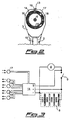
- an electric drill may include outer casing 1, usually made of plastic, which is divided into lower portion 2 acting as a handle and upper portion 3 comprising electric motor 4 and gearing system 5 for driving shaft 6.
- outer casing 1 usually made of plastic
- Handle 2 comprises a cavity 7 for housing battery 8 (shown only in Figure 3) and switch 9 provided with button 10 and connectors 11 coupling switch 9 to battery 8. By pushing button 10 of switch 9, the user can therefore control the supply power to motor 4 and thus the rotation of shaft 6.
- Three electric conductors suitably start from switch 9 and/or connectors 11, wherein the first conductor is connected to the positive pole of battery 8, the second conductor is connected to the negative pole of battery 8 and the third conductor is connected between the power supply and motor 4. Therefore, a variable voltage is supplied to motor 4 based upon the position of switch 9.
- These conductors pass through a hole provided in casing 1 and end in a tripolar male connector 12 disposed outside the casing 1.
- Such an external connector has been provided in known drills and thus, further details concerning the construction of the external connector are not necessary.
- Male connector 12 can be coupled to a complementary tripolar female connector 13 arranged at one end of a plurality of conductors terminating at the lighting device in the representative embodiment.
- This lighting device may comprise an electric circuit 14, and in particular may include a printed circuit board preferably having an annular shape, which is disposed around shaft 6.
- the printed circuit board may be kept in place by a protective cap 15 having a substantially cylindrical shape, which is fixed to the upper portion 3 of casing 1 of the drill.
- a plurality of light emitters 16 and a photometer 17 are disposed on the electric circuit 14 and protrude outside cap 15 through corresponding holes provided in the cap 15.
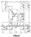
- electric circuit 14 has a ground terminal extending from the negative pole of battery 8. Terminal S extends from switch 9 and is connected to filter circuit A, which is adapted to eliminate possible spurious pulses caused by this switch.
- Filter circuit A comprises a resistor R1 connected in series to NOT logic gate GI, as well as resistor R2 and capacitor C1 connected in parallel to ground and disposed between resistor R1 and logic gate G1.
- the terminal extending from the positive pole of battery 8 is connected to a voltage limiting circuit B, which may include a resistor R3 and a Zener diode ZI connected in series to ground. Due to the Zener breakdown voltage of this diode, voltage limiting circuit B supplies a constant voltage, for instance 14 V, irrespective of the voltage of battery 8. Thus, Zener diode ZI provides a regulated power supply.
- a delay circuit C is connected downstream of filter circuit A and voltage limiting circuit B and is adapted to delay the turning off of the light emitters 16 after the power supply to motor 4 has stopped.
- Delay circuit C may comprise a diode D1 connected to logic gate G1 of circuit A and a resistor R4 connected in series to Zener diode Z1 of circuit B.
- Diode D1 and resistor R4 are connected to ground via a capacitor C2 and are further connected to a second NOT logic gate G2.
- the duration of the turning off delay of light emitters 16 is determined by the values of the resistance of resistor R4 and the capacitance of capacitor C2.
- a sensor circuit D is connected downstream of voltage limiting circuit B and comprises photometer 17, which may be a photodiode FD1.
- the photometer 17 is connected to ground via a capacitor C3 and is also connected to a third NOT logic gate G3, as well as to a resistor R5 and to a diode D2 connected in series.
- Photodiode FD1 is adapted to detect the intensity of ambient visible light
- photodiode FD1 detects wavelengths of between about 400 and 1100 nm.
- a modulator circuit E comprises a diode D3 adapted to modulate the lighting frequency of light emitters 16 according to the ambient light intensity detected by photodiode FD1 of sensor circuit D.
- Diode D3 is connected to logic gate G3 and diode D2 of sensor circuit D.
- Modulator circuit E also may comprise a resistor R6 connected to gate G2 of delay circuit C, as well as to diode D3 and to a fourth NOT logic gate G4.
- a buffer memory circuit F is connected downstream of logic gate G4 of modulator circuit E and may comprise a NOT logic gate G5, the output of which is connected to ground via a capacitor C4.
- Two on/off circuits G and H are connected in parallel to the output of logic gate G5, both respectively comprising a pair of BJT transistors TI, T2 and T3, T4 which are biased in a known manner by a pair of resistors R7, R8 and R9, R10. Resistors R8 and R10 are connected to ground. Circuits G and H control the turning on and off of light emitters 16 according to the signal output from logic gate G5. In the present embodiment, light emitters 16 are divided into two lighting circuits I and L, both comprising a pair of light emitting diodes, respectively LD1, LD2 and LD3, LD4, connected in series.
- Circuits I and L are arranged in parallel between the terminal extending from the positive pole of battery 8 and the collectors of transistors T2 and T4 of on/off circuits G and H, respectively.
- light emitting diodes LD1, LD2, LD3 and LD4 consist of high luminosity diodes of about 3 cd each.
- NOT logic gates GI, G2, G3, G4 and G5 may be known CMOS integrated circuits, which comprise 6 NOT logic gates and is powered by the output of voltage limiting circuit B.
- the part numbers for Diodes FD1 and LD1, LD2, LD3 and LD4 are part numbers of Siemens.
- the part number for Integrated Circuits G1, G2, G3, G4 and G5 is a part number of Fairchild.
- This representative power tool can be operated as follows. After battery 8 has been inserted into housing 7, the user can turn on motor 4 of the drill by pushing button 10 of switch 9. Thus, an electric voltage is transmitted to terminal S of filter circuit A of the electric circuit 14, which is already powered by the positive and negative terminals connected to battery 8. Filtered by circuit A, said signal passes through delay circuit C and is transformed by modulator circuit E into a square wave. The frequency of the square wave changes from about 20 Hz to about 20 kHz according to the ambient light intensity detected by photodiode FD1 of sensor circuit D.
- the on/off signal generated by modulator circuit E and held by buffer memory circuit F, is then transmitted to on/off circuits G and H, which from time to time turn on and off the diodes of circuits I and L according to said signal. Therefore, if the ambient light intensity is high, the light emitting diodes LD1, LD2, LD3 and LD4 turn on and off with a low frequency, so that also the illumination directed to the working point is low. On the other hand, if the ambient light intensity is low, said diodes turn on and off with a high frequency, so that also the illumination directed to the working point is high. When button 10 is released, the light continues to shine on the working area for a certain period of time, due to delay circuit C.
- the present embodiment relates to lighting devices have been applied to portable electric drills powered by a battery
- other embodiments of the present invention can relate to lighting devices applied to power tools of another types, such as for instance screwdrivers or other machine tools
- the power tools can be powered by an alternating current supplied by an external electric source, for example by a socket of an electric network, instead of a continuous current supplied by a battery.
- power tool may include a transformer and/or a voltage rectifier, if a transformer and/or a voltage rectifier have not already been provided in the power tool.
- controllers can be utilized to control the operating of the light emitters based upon the output of the ambient light detector, and the present teachings are not limited to the specific controller taught in the representative example.
Abstract
Description

Claims (12)
- Lighting device for machine tools, which comprises one or more light emitters (16) controlled by an electric circuit (14) suitable to be connected through one or more conductors to the inner circuit of an electric machine tool, characterized in that said electric circuit (14) comprises at least one photometer (17) and means (D, E, F, G, H) for automatically controlling the lighting of said light emitters (16) according to the luminous intensity sensed by said photometer (17).
- Device according to the previous claim, characterized in that said means (D, E, F, G, H) for automatically controlling the lighting of said light emitters (16) according to the luminous intensity sensed by said photometer (17) comprise a sensor circuit (D) provided with at least one photodiode (FD1) suitable to adjust the luminous intensity of said light emitters (16).
- Device according to the previous claim, characterized in that said sensor circuit (D) is connected to a modulator circuit (E) suitable to modulate the lighting frequency of the light emitters (16) according to the luminous intensity sensed by said photometer (17).
- Device according to the previous claim, characterized in that said modulator circuit (E) is connected to a buffer memory circuit (F) connected to one or more on/off circuits (G, H), each of them comprising one or more transistors (TI, T2, T3, T4) suitable to control the turning on and off of said light emitters (16).
- Device according to any previous claim, characterized in that said electric circuit (14) comprises at least one terminal (S) for the connection through one of said conductors to the switch (9) of the machine tool, as well as means (A, C) for controlling the lighting of said light emitters (16) according to the voltage sensed at said terminal (S).
- Device according to the previous claim, characterized in that said means (A, C) for controlling the lighting of said light emitters (16) according to the voltage sensed at said terminal (S) comprise at least one delay circuit (C).
- Device according to any previous claim, characterized in that said electric circuit (14) comprises a positive terminal and a negative terminal for the connection through a pair of said conductors to the electric power source (8) of the machine tool.
- Device according to the previous claim, characterized in that said electric circuit (14) comprises a voltage limiting circuit (B) suitable to limit the voltage of said electric power source (8).
- Device according to any previous claim, characterized in that said electric circuit (14) comprises a printed circuit having a substantially annular shape on which the light emitters (16) and the photometer (17) are arranged.
- Device according to any previous claim, characterized in that it comprises a protective cap (15), which is suitable to be fixed to the casing (1) of the machine tool and is provided with a plurality of holes for the light emitters (16) and the photometer (17), said electric circuit (14) suitable to be arranged between said cap (15) and said casing (1).
- Device according to any previous claim, characterized in that the light emitters (16) comprise one or more light emitting diodes (LD1, LD2, LD3, LD4).
- Electric machine tool, characterized in that it comprises at least a lighting device according to any previous claim.
Applications Claiming Priority (2)
| Application Number | Priority Date | Filing Date | Title |
|---|---|---|---|
| ITMI991722 | 1999-07-30 | ||
| IT99MI001722 IT1313279B1 (en) | 1999-07-30 | 1999-07-30 | LIGHTING DEVICE FOR ELECTRIC MACHINE TOOLS AND MACHINE TOOL INCLUDING SUCH DEVICE. |
Publications (3)
| Publication Number | Publication Date |
|---|---|
| EP1072842A2 true EP1072842A2 (en) | 2001-01-31 |
| EP1072842A3 EP1072842A3 (en) | 2001-10-10 |
| EP1072842B1 EP1072842B1 (en) | 2006-09-13 |
Family
ID=11383473
Family Applications (1)
| Application Number | Title | Priority Date | Filing Date |
|---|---|---|---|
| EP20000116429 Expired - Lifetime EP1072842B1 (en) | 1999-07-30 | 2000-07-28 | Power tools having lighting devices |
Country Status (5)
| Country | Link |
|---|---|
| US (1) | US6494590B1 (en) |
| EP (1) | EP1072842B1 (en) |
| JP (1) | JP2001057293A (en) |
| DE (1) | DE60030639D1 (en) |
| IT (1) | IT1313279B1 (en) |
Cited By (20)
| Publication number | Priority date | Publication date | Assignee | Title |
|---|---|---|---|---|
| WO2003061915A1 (en) * | 2002-01-21 | 2003-07-31 | Hitachi Koki Co., Ltd. | Power tool |
| US6890135B2 (en) | 2000-02-17 | 2005-05-10 | Credo Technology Corporation | Power tool with light emitting diode |
| EP1606979A2 (en) * | 2003-03-03 | 2005-12-21 | One World Technologies Limited | Battery-operated power tool with light source |
| US7131180B2 (en) | 2003-01-08 | 2006-11-07 | Credo Technology Corporation | Attachment for power tool |
| DE102008042652A1 (en) | 2008-10-07 | 2010-04-08 | Robert Bosch Gmbh | Electric tool and method for operating a power tool |
| DE102009011423A1 (en) * | 2009-03-03 | 2010-09-09 | Schneider Druckluft Gmbh | Pneumatic hand tool e.g. drilling press, has electrical lighting device provided with light and arranged at housing for lighting up work area of tool, and compressed air outlet provided for blowing compressed air |
| US7815356B2 (en) | 2006-09-25 | 2010-10-19 | Robert Bosch Gmbh | Illuminating hand-held power tool |
| US8317350B2 (en) | 2009-02-25 | 2012-11-27 | Black & Decker Inc. | Power tool with a light for illuminating a workpiece |
| WO2012171697A1 (en) * | 2011-06-14 | 2012-12-20 | Robert Bosch Gmbh | Hand-power tool |
| US8820955B2 (en) | 2009-02-25 | 2014-09-02 | Black & Decker Inc. | Power tool with light emitting assembly |
| US8827483B2 (en) | 2009-02-25 | 2014-09-09 | Black & Decker Inc. | Light for a power tool and method of illuminating a workpiece |
| US9028088B2 (en) | 2010-09-30 | 2015-05-12 | Black & Decker Inc. | Lighted power tool |
| US9242355B2 (en) | 2012-04-17 | 2016-01-26 | Black & Decker Inc. | Illuminated power tool |
| US9328915B2 (en) | 2010-09-30 | 2016-05-03 | Black & Decker Inc. | Lighted power tool |
| EP2524775A3 (en) * | 2011-05-19 | 2016-12-14 | Black & Decker Inc. | Power tool with light unit |
| US9722334B2 (en) | 2010-04-07 | 2017-08-01 | Black & Decker Inc. | Power tool with light unit |
| DE102016106560A1 (en) * | 2016-04-11 | 2017-10-12 | Festool Gmbh | The handheld machine tool |
| DE102009012690B4 (en) | 2009-03-11 | 2018-03-01 | Minebea Mitsumi Inc. | Voltage transformer and hand-held power tool with a voltage transformer |
| WO2020126731A1 (en) * | 2018-12-20 | 2020-06-25 | Robert Bosch Gmbh | Display apparatus for an electric tool |
| WO2020224824A1 (en) * | 2019-05-08 | 2020-11-12 | Festool Gmbh | Machine tool, in particular cordless drill or cordless screwdriver |
Families Citing this family (74)
| Publication number | Priority date | Publication date | Assignee | Title |
|---|---|---|---|---|
| JP3655124B2 (en) | 1999-05-14 | 2005-06-02 | 株式会社マキタ | Circular saw machine lighting equipment |
| JP3874990B2 (en) | 2000-04-18 | 2007-01-31 | 株式会社マキタ | Lighting equipment for cutting machine |
| JP3916883B2 (en) * | 2001-05-15 | 2007-05-23 | 株式会社マキタ | Electric tool |
| JP2002337101A (en) * | 2001-05-15 | 2002-11-27 | Makita Corp | Jigsaw |
| DE10155393A1 (en) * | 2001-11-10 | 2003-05-22 | Philips Corp Intellectual Pty | Planar polymer capacitor |
| JP3980900B2 (en) * | 2002-02-05 | 2007-09-26 | 株式会社マキタ | Angle drill |
| US6937336B2 (en) * | 2002-08-15 | 2005-08-30 | Black & Decker, Inc. | Optical alignment system for power tool |
| US20060076385A1 (en) * | 2002-04-18 | 2006-04-13 | Etter Mark A | Power tool control system |
| US8004664B2 (en) | 2002-04-18 | 2011-08-23 | Chang Type Industrial Company | Power tool control system |
| US11337728B2 (en) | 2002-05-31 | 2022-05-24 | Teleflex Life Sciences Limited | Powered drivers, intraosseous devices and methods to access bone marrow |
| DE60336939D1 (en) | 2002-05-31 | 2011-06-09 | Vidacare Corp | Device for access to bone marrow |
| US10973532B2 (en) | 2002-05-31 | 2021-04-13 | Teleflex Life Sciences Limited | Powered drivers, intraosseous devices and methods to access bone marrow |
| US8641715B2 (en) | 2002-05-31 | 2014-02-04 | Vidacare Corporation | Manual intraosseous device |
| US10973545B2 (en) | 2002-05-31 | 2021-04-13 | Teleflex Life Sciences Limited | Powered drivers, intraosseous devices and methods to access bone marrow |
| US8668698B2 (en) | 2002-05-31 | 2014-03-11 | Vidacare Corporation | Assembly for coupling powered driver with intraosseous device |
| US20030233921A1 (en) | 2002-06-19 | 2003-12-25 | Garcia Jaime E. | Cutter with optical alignment system |
| US7854054B2 (en) | 2003-01-08 | 2010-12-21 | Robert Bosch Tool Corporation | Attachment for power tool |
| US9504477B2 (en) | 2003-05-30 | 2016-11-29 | Vidacare LLC | Powered driver |
| US7080964B2 (en) * | 2003-08-26 | 2006-07-25 | Credo Technology Corporation | Tool chuck having a light transmitting capability |
| US7926187B2 (en) * | 2004-02-20 | 2011-04-19 | Milwaukee Electric Tool Corporation | Band saw |
| US8408327B2 (en) * | 2004-04-02 | 2013-04-02 | Black & Decker Inc. | Method for operating a power driver |
| US20060104732A1 (en) * | 2004-11-12 | 2006-05-18 | Yao-Ju Huang | Power Tool |
| US7404696B2 (en) * | 2005-02-18 | 2008-07-29 | Black & Decker Inc. | Drill driver with chuck-mounted drill accessories |
| US20060289595A1 (en) * | 2005-06-28 | 2006-12-28 | Basso Industry Corp. | Nailer with an illumination device |
| US7331685B2 (en) * | 2005-06-28 | 2008-02-19 | Basso Industry Corp. | Nailer with an illumination device |
| CN100364702C (en) * | 2005-12-06 | 2008-01-30 | 林丽钦 | Clamp connection head of boring apparatus with own lighting function |
| DE102005058613A1 (en) * | 2005-12-07 | 2007-06-14 | Bosch Rexroth Ag | Tool with non-contact switch |
| CN2871121Y (en) * | 2006-01-20 | 2007-02-21 | 南京德朔实业有限公司 | Electric tool with illuminator |
| EP1882553B1 (en) | 2006-07-26 | 2011-09-21 | Hitachi Koki Co., Ltd. | Power tool equipped with light |
| US8944069B2 (en) | 2006-09-12 | 2015-02-03 | Vidacare Corporation | Assemblies for coupling intraosseous (IO) devices to powered drivers |
| DE102006048719A1 (en) * | 2006-10-16 | 2008-04-17 | Robert Bosch Gmbh | System with a hand tool |
| WO2008124463A2 (en) * | 2007-04-04 | 2008-10-16 | Vidacare Corporation | Powered drivers, intraosseous devices and methods to access bone marrow |
| US20080295918A1 (en) * | 2007-06-04 | 2008-12-04 | Eastway Fair Company Limited | Router With Lighted Base |
| US20090070976A1 (en) * | 2007-09-17 | 2009-03-19 | Amirault Michael L | Non-Pneumatic Scaler |
| US8763258B2 (en) * | 2008-01-31 | 2014-07-01 | Black & Decker Inc. | Portable band saw |
| US20090256319A1 (en) * | 2008-04-09 | 2009-10-15 | Seymour Daniel R | Quick change chuck with led lighting |
| US20100000094A1 (en) * | 2008-07-01 | 2010-01-07 | Rachel Lombardo | Power tool with uv illumination |
| US20100002415A1 (en) * | 2008-07-01 | 2010-01-07 | Munn Jennifer R | Machine with uv illumination |
| US20100074700A1 (en) * | 2008-09-24 | 2010-03-25 | Icc Innovative Concepts Corporation | Electric drill with high efficiency illuminator |
| US20100071921A1 (en) * | 2008-09-24 | 2010-03-25 | Icc Innovative Concepts Corporation | Environmentally advantageous electric drill with efficiency promoting charge state indicator |
| JP2009078354A (en) * | 2008-12-05 | 2009-04-16 | Hitachi Koki Co Ltd | Power tool |
| JP5324976B2 (en) * | 2009-03-26 | 2013-10-23 | パナソニック株式会社 | Electric tool |
| JP5448578B2 (en) * | 2009-05-28 | 2014-03-19 | 株式会社マキタ | Electric tool with dust collecting function and dust collector for electric tool |
| CN201525002U (en) * | 2009-10-28 | 2010-07-14 | 南京德朔实业有限公司 | Electric hammer |
| CN102049762B (en) * | 2009-10-28 | 2012-08-22 | 南京德朔实业有限公司 | Electric hammer |
| CN201565934U (en) * | 2009-11-06 | 2010-09-01 | 南京德朔实业有限公司 | Electric hammer |
| JP2011104709A (en) * | 2009-11-17 | 2011-06-02 | Max Co Ltd | Power tool |
| CN102371573A (en) * | 2010-08-10 | 2012-03-14 | 南京德朔实业有限公司 | Electric tool |
| JP5671332B2 (en) * | 2010-12-27 | 2015-02-18 | 日立工機株式会社 | Electric tool |
| JP2013119149A (en) * | 2011-12-08 | 2013-06-17 | Makita Corp | Electric power tool |
| US9457462B2 (en) * | 2012-05-02 | 2016-10-04 | Milwaukee Electric Tool Corporation | Power tool having a speed selector switch |
| US20140196922A1 (en) * | 2013-01-17 | 2014-07-17 | Black & Decker Inc. | Electric power tool with improved visibility in darkness |
| FR3007308B1 (en) * | 2013-06-20 | 2015-07-03 | Castorama France | PORTABLE DRILLING MACHINE |
| US9370372B2 (en) * | 2013-09-04 | 2016-06-21 | Mcginley Engineered Solutions, Llc | Drill bit penetration measurement systems and methods |
| US9833244B2 (en) | 2013-11-08 | 2017-12-05 | Mcginley Engineered Solutions, Llc | Surgical saw with sensing technology for determining cut through of bone and depth of the saw blade during surgery |
| US9954418B2 (en) * | 2014-03-17 | 2018-04-24 | Makita Corporation | Power tool |
| FR3022477B1 (en) * | 2014-06-19 | 2017-02-24 | Castorama France | DRILLING MACHINE |
| WO2016036756A1 (en) | 2014-09-05 | 2016-03-10 | Mcginley Engineered Solutions, Llc | Instrument leading edge measurement system and method |
| US20160095177A1 (en) * | 2014-09-30 | 2016-03-31 | Chervon Intellectual Property Limited | Power tool |
| WO2017075224A1 (en) | 2015-10-27 | 2017-05-04 | Mcginley Engineered Solutions, Llc | Techniques and instruments for placement of orthopedic implants relative to bone features |
| WO2017075044A1 (en) * | 2015-10-27 | 2017-05-04 | Mcginley Engineered Solutions, Llc | Unicortical path detection for a surgical depth measurement system |
| EP3370629A4 (en) * | 2015-11-06 | 2019-07-24 | Mcginley Engineered Solutions LLC | Measurement system for use with surgical burr instrument |
| WO2017083989A1 (en) * | 2015-11-16 | 2017-05-26 | Ao Technology Ag | Surgical power drill including a measuring unit suitable for bone screw length determination |
| JP6922439B2 (en) * | 2017-06-02 | 2021-08-18 | マックス株式会社 | Portable power drive tool |
| US10987113B2 (en) | 2017-08-25 | 2021-04-27 | Mcginley Engineered Solutions, Llc | Sensing of surgical instrument placement relative to anatomic structures |
| WO2019070729A1 (en) | 2017-10-02 | 2019-04-11 | Mcginley Engineered Solutions, Llc | Surgical instrument with real time navigation assistance |
| JP7210261B2 (en) | 2018-12-14 | 2023-01-23 | 株式会社マキタ | ELECTRIC WORKING MACHINE AND METHOD FOR MANUFACTURING STATOR IN MOTOR FOR ELECTRIC WORKING MACHINE |
| DE102019111973B4 (en) | 2019-05-08 | 2022-01-13 | Festool Gmbh | Hand-held power tools, in particular cordless screwdrivers or cordless drills |
| JP7450203B2 (en) * | 2019-08-06 | 2024-03-15 | パナソニックIpマネジメント株式会社 | Electric tool |
| US11529180B2 (en) | 2019-08-16 | 2022-12-20 | Mcginley Engineered Solutions, Llc | Reversible pin driver |
| US11453106B2 (en) | 2019-10-25 | 2022-09-27 | Milwaukee Electric Tool Corporation | Rotary power tool having work light brightness control unit |
| EP4110555A4 (en) | 2020-02-24 | 2024-03-20 | Milwaukee Electric Tool Corp | Impact tool |
| US11672067B2 (en) | 2021-01-29 | 2023-06-06 | Snap-On Incorporated | Circuit board with sensor controlled lights and end-to-end connection |
| WO2023086237A1 (en) * | 2021-11-12 | 2023-05-19 | Milwaukee Electric Tool Corporation | Shadowless lighting system for a handheld power tool |
Family Cites Families (18)
| Publication number | Priority date | Publication date | Assignee | Title |
|---|---|---|---|---|
| US3919541A (en) | 1974-07-11 | 1975-11-11 | Albert A Chao | Screw driver{3 s light |
| US3977278A (en) | 1975-06-18 | 1976-08-31 | Lawrence Peska Associates, Inc. | Automotive electric impact wrench |
| DE2529668A1 (en) | 1975-07-03 | 1977-01-20 | Ewald Ebenhan | Electric hand-drill with inbuilt light - has light switched on by drill switch and shining on drill bit |
| FR2523891A1 (en) | 1982-03-25 | 1983-09-30 | Aerospatiale | Pneumatically operated hand tool - has turbine driven generator to provide electric light from bulb at end of flexible plastics arm in region of work |
| JPS6098602A (en) | 1983-11-02 | 1985-06-01 | 株式会社東芝 | Arrester |
| US4587459A (en) | 1983-12-27 | 1986-05-06 | Blake Frederick H | Light-sensing, light fixture control system |
| DE8521614U1 (en) | 1985-07-26 | 1986-01-16 | Demolski, Rolf, 5000 Köln | Portable machine tool |
| DE3738563A1 (en) | 1987-11-13 | 1989-05-24 | Frankl & Kirchner | Workplace light fixture |
| DE3831344C2 (en) | 1988-09-15 | 1993-10-07 | Fein C & E | Electric hand machine tool with switchable workplace lighting |
| US5169225A (en) | 1991-11-25 | 1992-12-08 | Milwaukee Electric Tool Corporation | Power tool with light |
| US5285708A (en) | 1992-05-18 | 1994-02-15 | Porter-Cable Corporation | Miter saw alignment system |
| US5420768A (en) * | 1993-09-13 | 1995-05-30 | Kennedy; John | Portable led photocuring device |
| US5473519A (en) | 1995-03-09 | 1995-12-05 | Ingersoll-Rand Company | Light ring for power tools |
| GB2305128B (en) | 1995-09-14 | 1998-05-06 | Glow Ball Ltd | Luminous device |
| CA2337203A1 (en) * | 1997-07-10 | 1999-01-21 | Avos Developments Limited | Illumination for power tools |
| JP4067158B2 (en) | 1997-12-05 | 2008-03-26 | 日立工機株式会社 | Portable circular saw |
| US6175196B1 (en) * | 1999-07-02 | 2001-01-16 | Gary Dean Ragner | Photo-sensitive illuminated skate wheel |
| JP2001025982A (en) | 1999-07-13 | 2001-01-30 | Makita Corp | Power tool with lighting system improved in operability, and its use |
-
1999
- 1999-07-30 IT IT99MI001722 patent/IT1313279B1/en active
-
2000
- 2000-07-13 JP JP2000213011A patent/JP2001057293A/en active Pending
- 2000-07-28 US US09/628,928 patent/US6494590B1/en not_active Expired - Lifetime
- 2000-07-28 DE DE60030639T patent/DE60030639D1/en not_active Expired - Lifetime
- 2000-07-28 EP EP20000116429 patent/EP1072842B1/en not_active Expired - Lifetime
Non-Patent Citations (1)
| Title |
|---|
| None |
Cited By (39)
| Publication number | Priority date | Publication date | Assignee | Title |
|---|---|---|---|---|
| US7094011B2 (en) | 2000-02-17 | 2006-08-22 | Credo Technology Corporation | Power tool |
| US6890135B2 (en) | 2000-02-17 | 2005-05-10 | Credo Technology Corporation | Power tool with light emitting diode |
| US7934847B2 (en) | 2002-01-21 | 2011-05-03 | Hitachi Koki Co., Ltd. | Power tool with light unit |
| EP2511049A1 (en) * | 2002-01-21 | 2012-10-17 | Hitachi Koki Co., Ltd. | Power tool |
| US7185998B2 (en) | 2002-01-21 | 2007-03-06 | Hitachi Koki Co., Ltd. | Power tool |
| WO2003061915A1 (en) * | 2002-01-21 | 2003-07-31 | Hitachi Koki Co., Ltd. | Power tool |
| US8517558B2 (en) | 2002-01-21 | 2013-08-27 | Hitachi Koki Co., Ltd. | Power tool |
| US7131180B2 (en) | 2003-01-08 | 2006-11-07 | Credo Technology Corporation | Attachment for power tool |
| EP1606979A4 (en) * | 2003-03-03 | 2010-06-16 | One World Technologies Ltd | Battery-operated power tool with light source |
| EP1606979A2 (en) * | 2003-03-03 | 2005-12-21 | One World Technologies Limited | Battery-operated power tool with light source |
| US7815356B2 (en) | 2006-09-25 | 2010-10-19 | Robert Bosch Gmbh | Illuminating hand-held power tool |
| DE102008042652A1 (en) | 2008-10-07 | 2010-04-08 | Robert Bosch Gmbh | Electric tool and method for operating a power tool |
| US9352458B2 (en) | 2009-02-25 | 2016-05-31 | Black & Decker Inc. | Power tool with light for illuminating workpiece |
| US8317350B2 (en) | 2009-02-25 | 2012-11-27 | Black & Decker Inc. | Power tool with a light for illuminating a workpiece |
| US8820955B2 (en) | 2009-02-25 | 2014-09-02 | Black & Decker Inc. | Power tool with light emitting assembly |
| US8827483B2 (en) | 2009-02-25 | 2014-09-09 | Black & Decker Inc. | Light for a power tool and method of illuminating a workpiece |
| DE102009011423A1 (en) * | 2009-03-03 | 2010-09-09 | Schneider Druckluft Gmbh | Pneumatic hand tool e.g. drilling press, has electrical lighting device provided with light and arranged at housing for lighting up work area of tool, and compressed air outlet provided for blowing compressed air |
| DE102009012690B4 (en) | 2009-03-11 | 2018-03-01 | Minebea Mitsumi Inc. | Voltage transformer and hand-held power tool with a voltage transformer |
| US9960509B2 (en) | 2010-04-07 | 2018-05-01 | Black & Decker Inc. | Power tool with light unit |
| US9722334B2 (en) | 2010-04-07 | 2017-08-01 | Black & Decker Inc. | Power tool with light unit |
| EP2420358A3 (en) * | 2010-08-18 | 2017-11-08 | Black & Decker Inc. | Power Tool with Light Emitting Assembly |
| US9028088B2 (en) | 2010-09-30 | 2015-05-12 | Black & Decker Inc. | Lighted power tool |
| US11090786B2 (en) | 2010-09-30 | 2021-08-17 | Black & Decker Inc. | Lighted power tool |
| US9644837B2 (en) | 2010-09-30 | 2017-05-09 | Black & Decker Inc. | Lighted power tool |
| US10543588B2 (en) | 2010-09-30 | 2020-01-28 | Black & Decker Inc. | Lighted power tool |
| US9328915B2 (en) | 2010-09-30 | 2016-05-03 | Black & Decker Inc. | Lighted power tool |
| EP2524775A3 (en) * | 2011-05-19 | 2016-12-14 | Black & Decker Inc. | Power tool with light unit |
| WO2012171697A1 (en) * | 2011-06-14 | 2012-12-20 | Robert Bosch Gmbh | Hand-power tool |
| CN103906604A (en) * | 2011-06-14 | 2014-07-02 | 罗伯特·博世有限公司 | Hand-power tool |
| CN103906604B (en) * | 2011-06-14 | 2017-07-04 | 罗伯特·博世有限公司 | Hand held power machine |
| US9539691B2 (en) | 2011-06-14 | 2017-01-10 | Robert Bosch Gmbh | Hand-power tool |
| US9242355B2 (en) | 2012-04-17 | 2016-01-26 | Black & Decker Inc. | Illuminated power tool |
| US10173307B2 (en) | 2012-04-17 | 2019-01-08 | Black & Decker Inc. | Illuminated power tool |
| DE102016106560A1 (en) * | 2016-04-11 | 2017-10-12 | Festool Gmbh | The handheld machine tool |
| WO2020126731A1 (en) * | 2018-12-20 | 2020-06-25 | Robert Bosch Gmbh | Display apparatus for an electric tool |
| WO2020224824A1 (en) * | 2019-05-08 | 2020-11-12 | Festool Gmbh | Machine tool, in particular cordless drill or cordless screwdriver |
| CN112423941A (en) * | 2019-05-08 | 2021-02-26 | 费斯托工具有限责任公司 | Electric tool, in particular cordless drill or cordless screwdriver |
| US11458548B2 (en) * | 2019-05-08 | 2022-10-04 | Festool Gmbh | Machine tool, in particular cordless drill or cordless screwdriver |
| CN112423941B (en) * | 2019-05-08 | 2023-10-20 | 费斯托工具有限责任公司 | Power tool, in particular cordless drill or cordless screwdriver |
Also Published As
| Publication number | Publication date |
|---|---|
| EP1072842B1 (en) | 2006-09-13 |
| DE60030639D1 (en) | 2006-10-26 |
| US6494590B1 (en) | 2002-12-17 |
| ITMI991722A1 (en) | 2001-01-30 |
| JP2001057293A (en) | 2001-02-27 |
| IT1313279B1 (en) | 2002-07-17 |
| EP1072842A3 (en) | 2001-10-10 |
| ITMI991722A0 (en) | 1999-07-30 |
Similar Documents
| Publication | Publication Date | Title |
|---|---|---|
| EP1072842A2 (en) | Power tools having lighting devices | |
| US11090786B2 (en) | Lighted power tool | |
| US9960509B2 (en) | Power tool with light unit | |
| US9328915B2 (en) | Lighted power tool | |
| US7282818B2 (en) | Power hand tool having a proximity detector | |
| US8344648B2 (en) | Electrical device, in particular an electric power tool or an electrical appliance | |
| JP3907950B2 (en) | Electric tool | |
| HK1063266A1 (en) | Power supply system for light emitting diode unit | |
| EP3603343B1 (en) | Dual led drive circuit | |
| EP2531009A1 (en) | Human sensor apparatus, human sensor system, and lighting control system | |
| EP2524775A2 (en) | Power tool with light unit | |
| CN207298454U (en) | Induction type light bulb | |
| JP4012081B2 (en) | Light source lighting circuit and lighting display device having the same | |
| CN107461622A (en) | induction type bulb | |
| JP2008047544A (en) | Light source lighting circuit, and light-emitting device equipped with the same | |
| US20230291223A1 (en) | Hand-Held Power Tool with a Work Field Lighting | |
| CN216391485U (en) | Lamp body control circuit and electric motor car | |
| CN220440964U (en) | Dimming circuit and driving power supply | |
| CN114430598B (en) | LED light sense lamp control circuit and LED lamp | |
| JPH0530371Y2 (en) | ||
| KR200318831Y1 (en) | Power supply condition indication network in guidance light | |
| KR200219052Y1 (en) | An electric tool with display device indicating Forwarding/Reversing direction | |
| JP2003236255A (en) | Rail of railroad model and point switching device thereof | |
| MXPA03011592A (en) | Control with a light change memory. | |
| CZ10093U1 (en) | Wiring for switching on additional dust collector electrical equipment |
Legal Events
| Date | Code | Title | Description |
|---|---|---|---|
| PUAI | Public reference made under article 153(3) epc to a published international application that has entered the european phase |
Free format text: ORIGINAL CODE: 0009012 |
|
| AK | Designated contracting states |
Kind code of ref document: A2 Designated state(s): DE FR GB IT SE Kind code of ref document: A2 Designated state(s): AT BE CH CY DE DK ES FI FR GB GR IE IT LI LU MC NL PT SE |
|
| AX | Request for extension of the european patent |
Free format text: AL;LT;LV;MK;RO;SI |
|
| PUAL | Search report despatched |
Free format text: ORIGINAL CODE: 0009013 |
|
| AK | Designated contracting states |
Kind code of ref document: A3 Designated state(s): AT BE CH CY DE DK ES FI FR GB GR IE IT LI LU MC NL PT SE |
|
| AX | Request for extension of the european patent |
Free format text: AL;LT;LV;MK;RO;SI |
|
| RIC1 | Information provided on ipc code assigned before grant |
Free format text: 7F 21V 33/00 A, 7F 21V 23/04 B, 7B 25F 5/02 B |
|
| 17P | Request for examination filed |
Effective date: 20011219 |
|
| AKX | Designation fees paid |
Free format text: DE FR GB IT SE |
|
| 17Q | First examination report despatched |
Effective date: 20040226 |
|
| GRAP | Despatch of communication of intention to grant a patent |
Free format text: ORIGINAL CODE: EPIDOSNIGR1 |
|
| GRAS | Grant fee paid |
Free format text: ORIGINAL CODE: EPIDOSNIGR3 |
|
| GRAA | (expected) grant |
Free format text: ORIGINAL CODE: 0009210 |
|
| AK | Designated contracting states |
Kind code of ref document: B1 Designated state(s): DE FR GB IT SE |
|
| PG25 | Lapsed in a contracting state [announced via postgrant information from national office to epo] |
Ref country code: IT Free format text: LAPSE BECAUSE OF FAILURE TO SUBMIT A TRANSLATION OF THE DESCRIPTION OR TO PAY THE FEE WITHIN THE PRESCRIBED TIME-LIMIT;WARNING: LAPSES OF ITALIAN PATENTS WITH EFFECTIVE DATE BEFORE 2007 MAY HAVE OCCURRED AT ANY TIME BEFORE 2007. THE CORRECT EFFECTIVE DATE MAY BE DIFFERENT FROM THE ONE RECORDED. Effective date: 20060913 |
|
| REG | Reference to a national code |
Ref country code: GB Ref legal event code: FG4D |
|
| REF | Corresponds to: |
Ref document number: 60030639 Country of ref document: DE Date of ref document: 20061026 Kind code of ref document: P |
|
| PG25 | Lapsed in a contracting state [announced via postgrant information from national office to epo] |
Ref country code: SE Free format text: LAPSE BECAUSE OF FAILURE TO SUBMIT A TRANSLATION OF THE DESCRIPTION OR TO PAY THE FEE WITHIN THE PRESCRIBED TIME-LIMIT Effective date: 20061213 |
|
| PG25 | Lapsed in a contracting state [announced via postgrant information from national office to epo] |
Ref country code: DE Free format text: LAPSE BECAUSE OF FAILURE TO SUBMIT A TRANSLATION OF THE DESCRIPTION OR TO PAY THE FEE WITHIN THE PRESCRIBED TIME-LIMIT Effective date: 20061214 |
|
| EN | Fr: translation not filed | ||
| PLBE | No opposition filed within time limit |
Free format text: ORIGINAL CODE: 0009261 |
|
| STAA | Information on the status of an ep patent application or granted ep patent |
Free format text: STATUS: NO OPPOSITION FILED WITHIN TIME LIMIT |
|
| 26N | No opposition filed |
Effective date: 20070614 |
|
| GBPC | Gb: european patent ceased through non-payment of renewal fee |
Effective date: 20070728 |
|
| PG25 | Lapsed in a contracting state [announced via postgrant information from national office to epo] |
Ref country code: FR Free format text: LAPSE BECAUSE OF FAILURE TO SUBMIT A TRANSLATION OF THE DESCRIPTION OR TO PAY THE FEE WITHIN THE PRESCRIBED TIME-LIMIT Effective date: 20070518 |
|
| PG25 | Lapsed in a contracting state [announced via postgrant information from national office to epo] |
Ref country code: GB Free format text: LAPSE BECAUSE OF NON-PAYMENT OF DUE FEES Effective date: 20070728 |
|
| PG25 | Lapsed in a contracting state [announced via postgrant information from national office to epo] |
Ref country code: FR Free format text: LAPSE BECAUSE OF FAILURE TO SUBMIT A TRANSLATION OF THE DESCRIPTION OR TO PAY THE FEE WITHIN THE PRESCRIBED TIME-LIMIT Effective date: 20060913 |
|
| PGFP | Annual fee paid to national office [announced via postgrant information from national office to epo] |
Ref country code: IT Payment date: 20190719 Year of fee payment: 20 |