EP1076797B1 - Seat with thermoelectric heat exchanger - Google Patents
Seat with thermoelectric heat exchanger Download PDFInfo
- Publication number
- EP1076797B1 EP1076797B1 EP99925590A EP99925590A EP1076797B1 EP 1076797 B1 EP1076797 B1 EP 1076797B1 EP 99925590 A EP99925590 A EP 99925590A EP 99925590 A EP99925590 A EP 99925590A EP 1076797 B1 EP1076797 B1 EP 1076797B1
- Authority
- EP
- European Patent Office
- Prior art keywords
- heat exchanger
- thermoelectric device
- air
- seat
- heat exchangers
- Prior art date
- Legal status (The legal status is an assumption and is not a legal conclusion. Google has not performed a legal analysis and makes no representation as to the accuracy of the status listed.)
- Expired - Lifetime
Links
- 239000012530 fluid Substances 0.000 claims abstract description 54
- 238000004891 communication Methods 0.000 claims abstract description 33
- 230000001143 conditioned effect Effects 0.000 claims abstract description 25
- 238000009423 ventilation Methods 0.000 claims abstract description 6
- 239000002699 waste material Substances 0.000 claims description 53
- 239000000463 material Substances 0.000 claims description 26
- 238000000034 method Methods 0.000 claims description 16
- 230000008859 change Effects 0.000 claims description 15
- 238000009826 distribution Methods 0.000 claims description 4
- 230000004044 response Effects 0.000 claims description 2
- 230000004888 barrier function Effects 0.000 claims 1
- 239000002918 waste heat Substances 0.000 claims 1
- 238000001816 cooling Methods 0.000 abstract description 18
- 238000010438 heat treatment Methods 0.000 abstract description 18
- 230000003750 conditioning effect Effects 0.000 abstract description 5
- 238000005086 pumping Methods 0.000 abstract description 2
- 239000007789 gas Substances 0.000 description 11
- 238000012546 transfer Methods 0.000 description 11
- 238000009413 insulation Methods 0.000 description 10
- 239000007788 liquid Substances 0.000 description 9
- 238000013461 design Methods 0.000 description 6
- 230000009467 reduction Effects 0.000 description 6
- 238000003860 storage Methods 0.000 description 6
- 230000008901 benefit Effects 0.000 description 5
- RYGMFSIKBFXOCR-UHFFFAOYSA-N Copper Chemical compound [Cu] RYGMFSIKBFXOCR-UHFFFAOYSA-N 0.000 description 4
- 229910052782 aluminium Inorganic materials 0.000 description 4
- XAGFODPZIPBFFR-UHFFFAOYSA-N aluminium Chemical compound [Al] XAGFODPZIPBFFR-UHFFFAOYSA-N 0.000 description 4
- 239000004020 conductor Substances 0.000 description 4
- 229910052802 copper Inorganic materials 0.000 description 4
- 239000010949 copper Substances 0.000 description 4
- 230000001965 increasing effect Effects 0.000 description 4
- XLYOFNOQVPJJNP-UHFFFAOYSA-N water Substances O XLYOFNOQVPJJNP-UHFFFAOYSA-N 0.000 description 4
- 239000000853 adhesive Substances 0.000 description 3
- 230000001070 adhesive effect Effects 0.000 description 3
- 238000004519 manufacturing process Methods 0.000 description 3
- 229910052751 metal Inorganic materials 0.000 description 3
- 239000002184 metal Substances 0.000 description 3
- XKRFYHLGVUSROY-UHFFFAOYSA-N Argon Chemical compound [Ar] XKRFYHLGVUSROY-UHFFFAOYSA-N 0.000 description 2
- IJGRMHOSHXDMSA-UHFFFAOYSA-N Atomic nitrogen Chemical compound N#N IJGRMHOSHXDMSA-UHFFFAOYSA-N 0.000 description 2
- 229920001247 Reticulated foam Polymers 0.000 description 2
- 241000555745 Sciuridae Species 0.000 description 2
- 238000009825 accumulation Methods 0.000 description 2
- 230000000712 assembly Effects 0.000 description 2
- 238000000429 assembly Methods 0.000 description 2
- 238000009833 condensation Methods 0.000 description 2
- 230000005494 condensation Effects 0.000 description 2
- 238000010276 construction Methods 0.000 description 2
- 239000004744 fabric Substances 0.000 description 2
- 230000008569 process Effects 0.000 description 2
- 238000000926 separation method Methods 0.000 description 2
- 241000894006 Bacteria Species 0.000 description 1
- OKTJSMMVPCPJKN-UHFFFAOYSA-N Carbon Chemical compound [C] OKTJSMMVPCPJKN-UHFFFAOYSA-N 0.000 description 1
- 229920000742 Cotton Polymers 0.000 description 1
- DGAQECJNVWCQMB-PUAWFVPOSA-M Ilexoside XXIX Chemical compound C[C@@H]1CC[C@@]2(CC[C@@]3(C(=CC[C@H]4[C@]3(CC[C@@H]5[C@@]4(CC[C@@H](C5(C)C)OS(=O)(=O)[O-])C)C)[C@@H]2[C@]1(C)O)C)C(=O)O[C@H]6[C@@H]([C@H]([C@@H]([C@H](O6)CO)O)O)O.[Na+] DGAQECJNVWCQMB-PUAWFVPOSA-M 0.000 description 1
- 239000004743 Polypropylene Substances 0.000 description 1
- XUIMIQQOPSSXEZ-UHFFFAOYSA-N Silicon Chemical compound [Si] XUIMIQQOPSSXEZ-UHFFFAOYSA-N 0.000 description 1
- BQCADISMDOOEFD-UHFFFAOYSA-N Silver Chemical compound [Ag] BQCADISMDOOEFD-UHFFFAOYSA-N 0.000 description 1
- 230000003213 activating effect Effects 0.000 description 1
- 238000004026 adhesive bonding Methods 0.000 description 1
- PNEYBMLMFCGWSK-UHFFFAOYSA-N aluminium oxide Inorganic materials [O-2].[O-2].[O-2].[Al+3].[Al+3] PNEYBMLMFCGWSK-UHFFFAOYSA-N 0.000 description 1
- 230000002528 anti-freeze Effects 0.000 description 1
- 229910052786 argon Inorganic materials 0.000 description 1
- QVGXLLKOCUKJST-UHFFFAOYSA-N atomic oxygen Chemical compound [O] QVGXLLKOCUKJST-UHFFFAOYSA-N 0.000 description 1
- 238000005452 bending Methods 0.000 description 1
- 229910052799 carbon Inorganic materials 0.000 description 1
- 235000014171 carbonated beverage Nutrition 0.000 description 1
- 230000015556 catabolic process Effects 0.000 description 1
- 238000004113 cell culture Methods 0.000 description 1
- 239000011248 coating agent Substances 0.000 description 1
- 238000000576 coating method Methods 0.000 description 1
- 238000007596 consolidation process Methods 0.000 description 1
- 230000008878 coupling Effects 0.000 description 1
- 238000010168 coupling process Methods 0.000 description 1
- 238000005859 coupling reaction Methods 0.000 description 1
- 230000007423 decrease Effects 0.000 description 1
- 238000006731 degradation reaction Methods 0.000 description 1
- 230000001419 dependent effect Effects 0.000 description 1
- 238000005516 engineering process Methods 0.000 description 1
- 230000002708 enhancing effect Effects 0.000 description 1
- 230000007613 environmental effect Effects 0.000 description 1
- 238000002474 experimental method Methods 0.000 description 1
- 239000001307 helium Substances 0.000 description 1
- 229910052734 helium Inorganic materials 0.000 description 1
- SWQJXJOGLNCZEY-UHFFFAOYSA-N helium atom Chemical compound [He] SWQJXJOGLNCZEY-UHFFFAOYSA-N 0.000 description 1
- 238000010348 incorporation Methods 0.000 description 1
- 230000001939 inductive effect Effects 0.000 description 1
- 239000012212 insulator Substances 0.000 description 1
- 239000010985 leather Substances 0.000 description 1
- 229910001338 liquidmetal Inorganic materials 0.000 description 1
- 230000007246 mechanism Effects 0.000 description 1
- 239000000203 mixture Substances 0.000 description 1
- 230000007935 neutral effect Effects 0.000 description 1
- 229910052757 nitrogen Inorganic materials 0.000 description 1
- 239000001301 oxygen Substances 0.000 description 1
- 229910052760 oxygen Inorganic materials 0.000 description 1
- 229920003023 plastic Polymers 0.000 description 1
- 239000004033 plastic Substances 0.000 description 1
- 239000002984 plastic foam Substances 0.000 description 1
- -1 polypropylene Polymers 0.000 description 1
- 229920001155 polypropylene Polymers 0.000 description 1
- 239000000565 sealant Substances 0.000 description 1
- 238000007789 sealing Methods 0.000 description 1
- 239000004065 semiconductor Substances 0.000 description 1
- 229910052710 silicon Inorganic materials 0.000 description 1
- 239000010703 silicon Substances 0.000 description 1
- 229910052709 silver Inorganic materials 0.000 description 1
- 239000004332 silver Substances 0.000 description 1
- 229910052708 sodium Inorganic materials 0.000 description 1
- 239000011734 sodium Substances 0.000 description 1
- 230000032258 transport Effects 0.000 description 1
- 238000011144 upstream manufacturing Methods 0.000 description 1
- 125000000391 vinyl group Chemical group [H]C([*])=C([H])[H] 0.000 description 1
- 229920002554 vinyl polymer Polymers 0.000 description 1
Images


Classifications
-
- B—PERFORMING OPERATIONS; TRANSPORTING
- B60—VEHICLES IN GENERAL
- B60N—SEATS SPECIALLY ADAPTED FOR VEHICLES; VEHICLE PASSENGER ACCOMMODATION NOT OTHERWISE PROVIDED FOR
- B60N2/00—Seats specially adapted for vehicles; Arrangement or mounting of seats in vehicles
- B60N2/56—Heating or ventilating devices
- B60N2/5607—Heating or ventilating devices characterised by convection
- B60N2/5621—Heating or ventilating devices characterised by convection by air
- B60N2/5635—Heating or ventilating devices characterised by convection by air coming from the passenger compartment
-
- B—PERFORMING OPERATIONS; TRANSPORTING
- B60—VEHICLES IN GENERAL
- B60H—ARRANGEMENTS OF HEATING, COOLING, VENTILATING OR OTHER AIR-TREATING DEVICES SPECIALLY ADAPTED FOR PASSENGER OR GOODS SPACES OF VEHICLES
- B60H1/00—Heating, cooling or ventilating [HVAC] devices
- B60H1/00457—Ventilation unit, e.g. combined with a radiator
- B60H1/00471—The ventilator being of the radial type, i.e. with radial expulsion of the air
-
- B—PERFORMING OPERATIONS; TRANSPORTING
- B60—VEHICLES IN GENERAL
- B60H—ARRANGEMENTS OF HEATING, COOLING, VENTILATING OR OTHER AIR-TREATING DEVICES SPECIALLY ADAPTED FOR PASSENGER OR GOODS SPACES OF VEHICLES
- B60H1/00—Heating, cooling or ventilating [HVAC] devices
- B60H1/00478—Air-conditioning devices using the Peltier effect
-
- B—PERFORMING OPERATIONS; TRANSPORTING
- B60—VEHICLES IN GENERAL
- B60H—ARRANGEMENTS OF HEATING, COOLING, VENTILATING OR OTHER AIR-TREATING DEVICES SPECIALLY ADAPTED FOR PASSENGER OR GOODS SPACES OF VEHICLES
- B60H1/00—Heating, cooling or ventilating [HVAC] devices
- B60H1/22—Heating, cooling or ventilating [HVAC] devices the heat being derived otherwise than from the propulsion plant
- B60H1/2215—Heating, cooling or ventilating [HVAC] devices the heat being derived otherwise than from the propulsion plant the heat being derived from electric heaters
- B60H1/2225—Heating, cooling or ventilating [HVAC] devices the heat being derived otherwise than from the propulsion plant the heat being derived from electric heaters arrangements of electric heaters for heating air
-
- B—PERFORMING OPERATIONS; TRANSPORTING
- B60—VEHICLES IN GENERAL
- B60N—SEATS SPECIALLY ADAPTED FOR VEHICLES; VEHICLE PASSENGER ACCOMMODATION NOT OTHERWISE PROVIDED FOR
- B60N2/00—Seats specially adapted for vehicles; Arrangement or mounting of seats in vehicles
- B60N2/56—Heating or ventilating devices
- B60N2/5607—Heating or ventilating devices characterised by convection
- B60N2/5621—Heating or ventilating devices characterised by convection by air
- B60N2/5657—Heating or ventilating devices characterised by convection by air blown towards the seat surface
-
- B—PERFORMING OPERATIONS; TRANSPORTING
- B60—VEHICLES IN GENERAL
- B60N—SEATS SPECIALLY ADAPTED FOR VEHICLES; VEHICLE PASSENGER ACCOMMODATION NOT OTHERWISE PROVIDED FOR
- B60N2/00—Seats specially adapted for vehicles; Arrangement or mounting of seats in vehicles
- B60N2/56—Heating or ventilating devices
- B60N2/5678—Heating or ventilating devices characterised by electrical systems
- B60N2/5685—Resistance
-
- B—PERFORMING OPERATIONS; TRANSPORTING
- B60—VEHICLES IN GENERAL
- B60N—SEATS SPECIALLY ADAPTED FOR VEHICLES; VEHICLE PASSENGER ACCOMMODATION NOT OTHERWISE PROVIDED FOR
- B60N2/00—Seats specially adapted for vehicles; Arrangement or mounting of seats in vehicles
- B60N2/56—Heating or ventilating devices
- B60N2/5678—Heating or ventilating devices characterised by electrical systems
- B60N2/5692—Refrigerating means
-
- F—MECHANICAL ENGINEERING; LIGHTING; HEATING; WEAPONS; BLASTING
- F04—POSITIVE - DISPLACEMENT MACHINES FOR LIQUIDS; PUMPS FOR LIQUIDS OR ELASTIC FLUIDS
- F04D—NON-POSITIVE-DISPLACEMENT PUMPS
- F04D17/00—Radial-flow pumps, e.g. centrifugal pumps; Helico-centrifugal pumps
- F04D17/08—Centrifugal pumps
- F04D17/16—Centrifugal pumps for displacing without appreciable compression
- F04D17/162—Double suction pumps
-
- F—MECHANICAL ENGINEERING; LIGHTING; HEATING; WEAPONS; BLASTING
- F04—POSITIVE - DISPLACEMENT MACHINES FOR LIQUIDS; PUMPS FOR LIQUIDS OR ELASTIC FLUIDS
- F04D—NON-POSITIVE-DISPLACEMENT PUMPS
- F04D25/00—Pumping installations or systems
- F04D25/16—Combinations of two or more pumps ; Producing two or more separate gas flows
- F04D25/166—Combinations of two or more pumps ; Producing two or more separate gas flows using fans
-
- F—MECHANICAL ENGINEERING; LIGHTING; HEATING; WEAPONS; BLASTING
- F04—POSITIVE - DISPLACEMENT MACHINES FOR LIQUIDS; PUMPS FOR LIQUIDS OR ELASTIC FLUIDS
- F04D—NON-POSITIVE-DISPLACEMENT PUMPS
- F04D29/00—Details, component parts, or accessories
- F04D29/40—Casings; Connections of working fluid
- F04D29/42—Casings; Connections of working fluid for radial or helico-centrifugal pumps
- F04D29/4206—Casings; Connections of working fluid for radial or helico-centrifugal pumps especially adapted for elastic fluid pumps
- F04D29/4226—Fan casings
- F04D29/4246—Fan casings comprising more than one outlet
-
- F—MECHANICAL ENGINEERING; LIGHTING; HEATING; WEAPONS; BLASTING
- F04—POSITIVE - DISPLACEMENT MACHINES FOR LIQUIDS; PUMPS FOR LIQUIDS OR ELASTIC FLUIDS
- F04D—NON-POSITIVE-DISPLACEMENT PUMPS
- F04D29/00—Details, component parts, or accessories
- F04D29/58—Cooling; Heating; Diminishing heat transfer
- F04D29/582—Cooling; Heating; Diminishing heat transfer specially adapted for elastic fluid pumps
- F04D29/5826—Cooling at least part of the working fluid in a heat exchanger
-
- F—MECHANICAL ENGINEERING; LIGHTING; HEATING; WEAPONS; BLASTING
- F25—REFRIGERATION OR COOLING; COMBINED HEATING AND REFRIGERATION SYSTEMS; HEAT PUMP SYSTEMS; MANUFACTURE OR STORAGE OF ICE; LIQUEFACTION SOLIDIFICATION OF GASES
- F25B—REFRIGERATION MACHINES, PLANTS OR SYSTEMS; COMBINED HEATING AND REFRIGERATION SYSTEMS; HEAT PUMP SYSTEMS
- F25B21/00—Machines, plants or systems, using electric or magnetic effects
- F25B21/02—Machines, plants or systems, using electric or magnetic effects using Peltier effect; using Nernst-Ettinghausen effect
- F25B21/04—Machines, plants or systems, using electric or magnetic effects using Peltier effect; using Nernst-Ettinghausen effect reversible
-
- F—MECHANICAL ENGINEERING; LIGHTING; HEATING; WEAPONS; BLASTING
- F28—HEAT EXCHANGE IN GENERAL
- F28D—HEAT-EXCHANGE APPARATUS, NOT PROVIDED FOR IN ANOTHER SUBCLASS, IN WHICH THE HEAT-EXCHANGE MEDIA DO NOT COME INTO DIRECT CONTACT
- F28D11/00—Heat-exchange apparatus employing moving conduits
- F28D11/02—Heat-exchange apparatus employing moving conduits the movement being rotary, e.g. performed by a drum or roller
-
- H—ELECTRICITY
- H10—SEMICONDUCTOR DEVICES; ELECTRIC SOLID-STATE DEVICES NOT OTHERWISE PROVIDED FOR
- H10N—ELECTRIC SOLID-STATE DEVICES NOT OTHERWISE PROVIDED FOR
- H10N10/00—Thermoelectric devices comprising a junction of dissimilar materials, i.e. devices exhibiting Seebeck or Peltier effects
- H10N10/10—Thermoelectric devices comprising a junction of dissimilar materials, i.e. devices exhibiting Seebeck or Peltier effects operating with only the Peltier or Seebeck effects
- H10N10/13—Thermoelectric devices comprising a junction of dissimilar materials, i.e. devices exhibiting Seebeck or Peltier effects operating with only the Peltier or Seebeck effects characterised by the heat-exchanging means at the junction
-
- F—MECHANICAL ENGINEERING; LIGHTING; HEATING; WEAPONS; BLASTING
- F25—REFRIGERATION OR COOLING; COMBINED HEATING AND REFRIGERATION SYSTEMS; HEAT PUMP SYSTEMS; MANUFACTURE OR STORAGE OF ICE; LIQUEFACTION SOLIDIFICATION OF GASES
- F25B—REFRIGERATION MACHINES, PLANTS OR SYSTEMS; COMBINED HEATING AND REFRIGERATION SYSTEMS; HEAT PUMP SYSTEMS
- F25B2321/00—Details of machines, plants or systems, using electric or magnetic effects
- F25B2321/02—Details of machines, plants or systems, using electric or magnetic effects using Peltier effects; using Nernst-Ettinghausen effects
- F25B2321/025—Removal of heat
- F25B2321/0251—Removal of heat by a gas
-
- Y—GENERAL TAGGING OF NEW TECHNOLOGICAL DEVELOPMENTS; GENERAL TAGGING OF CROSS-SECTIONAL TECHNOLOGIES SPANNING OVER SEVERAL SECTIONS OF THE IPC; TECHNICAL SUBJECTS COVERED BY FORMER USPC CROSS-REFERENCE ART COLLECTIONS [XRACs] AND DIGESTS
- Y02—TECHNOLOGIES OR APPLICATIONS FOR MITIGATION OR ADAPTATION AGAINST CLIMATE CHANGE
- Y02B—CLIMATE CHANGE MITIGATION TECHNOLOGIES RELATED TO BUILDINGS, e.g. HOUSING, HOUSE APPLIANCES OR RELATED END-USER APPLICATIONS
- Y02B30/00—Energy efficient heating, ventilation or air conditioning [HVAC]
Definitions
- the present invention relates to a seat, such as an automobile seat, with a temperature controlled ventilation system.
- Modern automobile seats may be equipped with temperature control systems that allow the occupant to vary the temperature of the seat by flowing temperature-controlled air through the seat covering (see for instance WO-A-95/14899).
- One type of system comprises a seat having a heat transfer system mounted therein, such as a thermoelectric element configured to heat or cool air that is moved over the element using a separate fan unit that is also mounted within the seat. The conditioned air is distributed to the occupant by passing the air through the seat surface via a series of air ducts within the seat.
- the amount of space available within, below and around the seat for such temperature control systems is severely limited.
- the seats are a few inches thick and abut the adjacent structure of the car, such as the floorboard or the back of the car.
- automobile manufacturers are increasingly mounting various devices, such as electronic components or variable lumbar supports, within, below and around the seat.
- the size of the seat, particularly the seat back needs to be as small as possible to reduce the amount of cabin space consumed by the seat.
- Present temperature control systems are often too large to be mounted within, below or around vehicle seats.
- Conventional systems may have a squirrel cage fan five or six inches in diameter generating an air flow that passes through a duct to reach a heat exchanger that adjusts the temperature of the air.
- the heat exchanger is several inches wide and long, and at least an inch or so thick. From the heat exchanger the air is transported through ducts to the bottom of the seat cushion and to the back of the seat cushion.
- Such systems are bulky and difficult to fit underneath or inside car seats.
- Using thermoelectric devices to heat and cool the heat exchanger helps reduce the size of unit, but still requires a large volume for the combined heating and cooling system.
- the ducting used with these systems is also bulky and difficult to use if the duct must go from a seat bottom to a seat back that is allowed to pivot or rotate. These ducts not only use additional space within the seat, but also resist air flow and thus require a larger fan to provide the air flow, and the larger fan requires additional space or else runs at greater speeds and generates more noise. Noise is undesirable inside motor vehicles. Further, the ducting affects the temperature of the passing air and either heats cool air, or cools heated air, with the result of often requiring larger fans or heat exchangers.
- This device uses air flow generators, such as fan blades, that act as both a heat exchanger to transfer a thermal differential from a thermoelectric device and thereby condition air passing over the heat exchanger, and that act as an air pump.
- the heat exchanger rotates and provides aerodynamic and centrifugal force to the air passing through the heat exchanger to generate pressurized air for distribution, such as to the seat of a motor vehicle.
- one embodiment of this device comprises at least one annular thermoelectric device (e.g., Peltier device) that, depending on the voltage applied, heats one surface and cools the opposing surface of the annular, thermoelectric device.
- Annular heat exchangers are placed in thermal communication with the opposing sides of the annular thermoelectric device by mounting them directly to the thermoelectric device so that each heat exchanger conducts the heat or cold from the surface of the device to which the heat exchanger is mounted.
- a resistive heating element may also be used to generate heat.
- the annular heat exchangers are formed with radial slots extending through the heat exchanger, and form an annular cavity inside the heat exchangers when assembled.
- a motor nests inside the annular cavity formed on the inside of the assembled annular heat exchangers and annular, thermoelectric device, but spaced apart from the heat exchangers and thermoelectric device by an amount sufficient to allow air to flow along the exterior of the motor.
- the motor is drivingly connected to one of the heat exchangers and thermoelectric device to rotate them.
- the rotating heat exchangers act as a fan, drawing air into the annular cavity and expelling the air through the radial slots of the heat exchangers at a higher pressure.
- the volume of compressed air created is determined by the motor size, the fan blade shape, the rotational speed, and the overall geometry of the assembly.
- This arrangement allows the heat exchanger to be directly coupled to the thermoelectric device, and to act as a fan to not only generate the air pressure that distributes the conditioned air to passenger seats, but to condition the air as the air passes through the fan blades/heat exchanger.
- This reduces ducting and associated pressure losses, reduces the size of the system, and increases the overall efficiency of the system which in turn allows a reduction in fan size and power requirements.
- the compact arrangement allows the system to be placed underneath, and preferably inside most automobile seats, which further reduces ducting and associated pressure losses, and allows further reductions in motor size and power. The result of the various reductions is some combination of a smaller system volume, less power consumption, smaller size, and generation of less noise, than previously available.
- a seal separates the opposing sides of the rotating, annular heat exchangers to form a main, or supply side and a waste side.
- Air enters the assembly near the axis of rotation, which advantageously is aligned with the motor's rotational axis. The air exits radially or axially outward into a housing enclosing the majority of the annular fan/heat exchanger.
- An outlet in fluid communication with the main (or supply) side is in fluid communication with the seat of a passenger vehicle.
- An outlet in fluid communication with the waste side is also in fluid communication with an outlet at a location that will not degrade performance by allowing the waste air to be recirculated to the air entry portion.
- the thermoelectric creates a temperature differential between the supply side air and the waste side air. Layers of thermal insulation between the waste side and the supply side help maintain that temperature differential in portions of the assembly.
- thermoelectric device Power is supplied to the thermoelectric device by brush and slip ring assemblies on the rotational axis of the motor.
- a flow of either cold or hot air is provided to the supply side by the heat exchanger that conducts the temperature differential throughout the heat exchanger, and heats or cools the air passing over the heat exchanger/fan blades by conduction and convection. Voltage adjustments to the motor and thermoelectric control the pressure, temperature and flow rate.
- a wicking material is placed so that the material extends from the supply side to the waste side. If moisture condenses on one rotating fan, it is urged against the wicking material by centrifugal force from the rotating fan/heat exchanger. The wicking material absorbs the moisture, and transports the moisture to the opposing side where heated air evaporates the moisture and carries the moisture out of the system.
- the system comprises an electronic device selected to convert electrical energy into thermal energy producing a temperature change in response to an electrical current being applied thereto.
- the electronic device is mounted to rotate about a rotational axis.
- a heat transfer device is placed in conductive thermal communication with the electronic device and is mounted to rotate about the axis.
- the heat transfer device has thermally radiating surfaces arranged to produce a fluid flow across the surfaces when rotated about the axis.
- the electronic device can comprise a heating resistor, or a thermoelectric device that can heat or cool the fluid.
- the heat transfer device comprises a first series of outwardly-extending thermally radiating surfaces connected to a first surface of the electric device.
- a second series of thermally radiating surfaces may be connected to an opposing, second surface of the thermoelectric device.
- the heat transfer device is contained in a housing having at least one outlet in fluid communication with a seat.
- the present invention also includes a means for producing a temperature change and a rotating supply side heat exchanger means for conducting the temperature change.
- the heat exchanger means further comprises fluid flow generating means for causing fluid to flow across said heat exchanger means.
- the fluid advantageously comprises a gas and the supply side heat exchanger means is advantageously in fluid communication with a seat to provide gas from the heat exchanger means to the seat.
- the apparatus also comprises a device for thermally conditioning a fluid having a first fan rotating about a rotational axis and having a first plurality of heat exchange surfaces in conductive thermal communication with an electronic device that converts electrical energy into a temperature change.
- the fan is advantageously enclosed in a housing that has an outlet.
- the present invention also comprises a method for thermally conditioning a fluid comprising the steps of producing a temperature change by an electronic device, conducting that temperature change to a heat exchanger having radiative surfaces, and rotating the radiative surfaces to cause fluid to flow across the radiative surfaces.
- a heat exchanger having radiative surfaces
- the fluid comprises a gas, preferably air.
- the thermally conditioned fluid is circulated to the interior of a chamber which may comprise a gas plenum, or circulated to a thermally insulated chamber provided with a closable opening to allow access to the interior of the chamber - such as a cooler.
- One method for producing a very compact form of the invention is to form a first heat exchanger having radiative surfaces aligned to allow the passage of air outward from an axis about which the heat exchanger rotates.
- the first heat exchanger is placed in conductive thermal communication with an electrical device that generates a temperature change when an electrical current is applied to the electrical device.
- the first heat exchanger is then rotated about the axis.
- the electrical device comprises a thermoelectric device, and when placed inside a vehicle seat, provides a compact unit for ventilating the seat.
- the present invention further comprises means for producing a temperature differential and supply side heat exchanger means for conducting said temperature change, where the heat exchanger means further comprises fluid flow generating means for causing fluid to flow across said heat exchanger means.
- the supply side heat exchanger means is in fluid communication with a vehicle seat.
- a further version of the invention comprises a first fan rotating about a rotational axis and having a first plurality of heat exchange elements configured to generate a fluid flow through the heat exchange elements when rotated and in conductive thermal communication with an electronic device that converts electrical energy into a temperature change.
- the fan is advantageously enclosed in a housing that has an outlet in fluid communication with a fluid distribution system, and preferably the electronic device comprises a thermoelectric device.
- thermoelectric device generates a temperature change that is conducted to a heat exchanger which forms an impeller to cause fluid to flow across the heat exchanger and thermally condition the fluid.
- the thermally conditioned fluid may be placed in thermal communication with a variety of objects, one of which is a vehicle seat to provide localized heating and cooling of a person sitting on the seat.
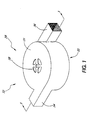
- the heat exchanger unit 28 of the present invention includes an outer housing 32 that defines an interior cavity 29 ( Figure 3) in which a rotor assembly 30 ( Figures 2 and 3) is rotatably mounted for producing a conditioned airflow into and out of the outer housing 32.
- the outer housing 32 is shown as resembling a generally flat disc with a first surface or first wall 31 that corresponds to an upper or top surface if the housing 32 is placed in a seat bottom generally parallel to the ground.
- up or upper will refer to a direction away from the ground.
- lower or bottom will refer to a direction toward the ground.
- the relative direction of parts would alter if the entire orientation of housing 32 were changed, as may occur in actual use.
- a second wall 33 corresponding to a bottom surface, is opposite the first wall 31.
- the generally circular peripheries of walls 31, 33 are joined by side wall 35 to form an enclosure.
- a first outlet 34 extends outwardly from the side wall 35 adjacent the first or upper wall 31 of the outer housing 32.
- a second outlet 36 extends outwardly from the side wall 35 adjacent the second, or lower wall 33.
- the outlets 34, 36 extend generally tangential from the periphery of the housing 32.
- the outlets 34, 36 are shown extending in generally opposite directions, about 180 relative to each other. But depending on the particular direction the air needs to flow, the outlets 34, 36 could be located at other angles relative to each other, with 60, 90 on either side of the housing 32, being the most likely relative positions.
- the outlets 34, 36 could exit in the same direction if desired, but then it would be advantageous to have insulation between the outlets to help maintain the temperature differential between the outlets.
- a set of apertures 38 are centrally formed in the first or top wall 31 of the outer housing 32 to form a first inlet 38 that communicates with the interior cavity 29 formed and enclosed by the outer housing 32.
- a second inlet 40 ( Figure 3) may also be located on the second or bottom wall 33 of the outer housing 32 opposite the first inlet 38.
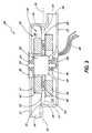
- the rotor assembly 30 generally comprises a plurality of components including an annular first rotor 42, an annular second rotor 44 disposed below the first rotor 42, and at least one annular thermoelectric device 46 interposed between, and in thermal communication with, the first rotor 42 and the second rotor 44.
- the thermoelectric device is also known as a Peltier device which comprises at least one pair of dissimilar materials connected electrically in series and thermally in parallel, and typically comprises a series of n-type and p-type semiconductor elements connected electrically in series and thermally in parallel. Depending on the direction of current passing through the thermoelectric device 46, one surface will be heated and the opposing surface will be cooled.
- the thermoelectric device 46 generates a temperature differential that causes heat to transfer by conduction through the rotors 42, 44.
- the greater the temperature differential the greater the rate of heat transfer.
- Current thermoelectric devices can generate a temperature differential of 70 C across the opposing surfaces of the thermoelectric device, and if the devices are stacked, temperature differentials of 130 C are currently possible. The temperature differentials and efficiencies are expected to increase as the technology improves.
- the rotors 42, 44 comprise annular heat exchangers in direct thermal communication with the thermoelectric device 46 to conduct heat throughout the rotors 42, 44, primarily by thermal conduction to thereby form a short thermal path length between the rotors 42, 44 and the thermoelectric device 46.
- the rate of thermal conduction will vary.
- the rotors 42, 44 also allow air to pass outward, such as in a radial direction, through the heat exchanger, and further comprise blades of fans that cause the air to pass outward through the rotors 42, 44.
- the heat exchanger thus forms the fan that causes the air to flow through the heat exchanger.
- the fan that generates the air flow also forms the heat exchanger.
- the fins of the heat exchanger comprise the blades or airfoils of the fan generating the air flow.
- the heat exchanger could comprise a series of heat exchange surfaces that are configured to generate an airflow when the surfaces are rotated.
- the rotors 42, 44 are advantageously formed by taking a length of heat exchanger of aluminum or copper that is formed from a flat strip of metal having corrugated or accordion-like pleats folded so heat sinks and sources can be connected at the ends of the pleats where the metal folds to change direction.
- the pleats are orientated so air can flow along the corrugations of the heat exchanger.
- the opposing ends of that length of heat exchanger are curved toward each other, and then overlapped and fastened together either mechanically or by thermal or adhesive bonding. This bending forms the previously straight length into a circle so the air flows radially through what is now a circular heat exchanger. In this annular configuration the heat exchanger can effectively act as the blades of a squirrel cage fan or a circular fan. This method is advantageously used to form both the first rotor 42 and the second rotor 44.
- the first rotor 42 is located on the supply side of the heat exchanger that supplies conditioned air to a user, and has an outer diameter that is smaller than the diameter of the second rotor 44.
- the second rotor 44 is located on the waste side of the system and exhausts conditioned air, advantageously to a location that does not direct air to the supply side or that otherwise directs air to a location that could affect the user.
- Each of the components are axially aligned to rotate about a central axis aligned with a drive shaft or axle 52 of motor 50.
- a disc-shaped connector 51 having a central aperture is disposed on top of the first rotor 42 and the motor 50.
- the motor 50 may be directly coupled to the axle 52 or could be indirectly coupled, such as via a gear assembly.
- the connector 51 mechanically couples at least one of the shaft 52 or motor 50 to the first rotor 42 so that the motor 50 is configured to rotatably drive the first rotor 42, the thermoelectric device 46, and the second rotor 44 about a common axis, as described in more detail below.
- the interior diameter of rotors 42, 44 is advantageously large enough to allow motor 50 to be inserted inside the space formed inside the annular rotors 42, 44, to minimize the height of the unit along the longitudinal axis about which rotors 42, 44 rotate.
- the rotor assembly 30 is mounted within the outer housing 32 on a drive axle 52 that, in the illustrated embodiment, is journaled at opposing ends of the axle on shaft bearings 54 which are advantageously mounted to walls 31, 33.
- the drive axle 52 of the rotor assembly 30 is axially aligned with the first and second inlets 38 and 40 of the outer housing 32.
- the outer housing 32 could also be equipped with only a single inlet or with more than two inlets.
- the plane of the thermoelectric device 46 defines a boundary line 56 that divides the interior cavity 29 into an upper portion or supply side 58 and a lower portion or waste side 60.
- the first rotor 42 is located within the upper portion or supply side 58 and the second rotor 44 is located within the lower portion or waste side 60.
- the rotor assembly 30 further includes a first annular plate 63 that is disposed between a top edge of the thermoelectric device 46 and a bottom edge of the first rotor 42.
- a second annular plate 65 is disposed between a bottom edge of the thermoelectric device 46 and the top of the second rotor 44 so that the thermoelectric device 46 is interposed between the first and second plates 63 and 65.
- the first and second plates 63 and 65 are preferably manufactured of a material that is thermally conductive but is electrically insulative, such as, for example, alumina.
- a heat-resistant, thermally-conductive adhesive such as silver-filled silicon adhesive, is used to mount the first rotor 42 to the first plate 63 and the second rotor 44 to the second plate 65.
- plates 63 and 65 may be omitted and the first and second rotors 42 and 44 may be directly attached to the thermoelectric device 46.
- An annular, disc-like insulation member 64 of thermally insulated material extends from between the rotors 42, 44, radially outward and ends before it hits the inside of the side walls 35.
- the member 64 is positioned on top of the second annular plate 65 adjacent the inner and outer periphery of the thermoelectric device 46 and is placed generally in the plane containing boundary line 56.
- the insulation member 64 is dimensioned to extend radially inward and outward from the thermoelectric device toward the motor 50 along the boundary line 56.
- a gap 66 is defined between the outer periphery of the insulation disc 64 and the interior surface of the outer housing 32, with the gap 66 forming an air bearing to reduce the passage of air across the gap 66.
- a thin and flexible annular seal 70 of thermally insulated material is positioned so as to extend radially inward from the interior surface of the outer housing 32 generally along the boundary line 56.
- the annular seal 70 is preferably sized so that it overlaps, but does not contact the adjacent surface of the insulation member 64.
- the annular seal 70 cooperates with the insulation member 64 to define a labyrinth seal around the outer periphery of the member 64 that thermally insulates the upper portion or supply side 58 of the interior cavity 29 from the lower portion or waste side 60 of the interior cavity 29.
- the insulation member 64 and annular seal 70 prevent significant heat convection between the waste and main sides.
- the annular seal 70 can be in the form of an air bearing that facilitates rotation of the rotor assembly 30.
- the insulation member 64 may comprise any of a wide variety of heat resistant, thermally-insulative materials, such as expanded polypropylene.
- At least a portion of the interior surface of the housing 32 advantageously is coated with a wicking material 78 that is adapted to absorb and conduct moisture.
- the wicking material 78 extends between the upper and lower portions 58, 60, and advantageously comprises a woven cotton fabric that has been texture coated to prevent microbe growth.
- the wicking material 78 absorbs condensed moisture expelled by centrifugal force from whichever rotor 42, 44 produces the condensation, and conducts the moisture to the other rotor where it is evaporated by the heated air - in order to avoid accumulation in the interior cavity 33 and in passages distributing the cooled air.
- the wicking material 78 absorbs enough moisture to prevent accumulation in the downstream passages in fluid communication with whichever rotor 42, 44 is cooled prompting a potential for condensation.
- the annular seal 70 must allow the wicking material 78 to pass.
- the seal 70 may be connected to an exterior surface of the material 78, may extend through the material 78 at intermittent locations, or may connect to side walls 35 at locates where the material 78 is absent.
- the material 70 could also extend outside of the interior cavity 33.
- thermoelectric device 46 electrically-conductive wires 80 are electrically coupled to the thermoelectric device 46 to provide an electrical potential thereto in a well known manner through brushes 84 that are in electrical communication with the rotating drive axle 52. Because electrical current must be provided to the thermoelectric device 46 in a closed circuit, two brushes 84 are in electrical communication with the axle 52 and thermoelectric 46 through brush and slip-ring assemblies known in the art. Other electrical connections, such as, for example, an inductive coupling, can be devised given the present disclosure.
- Figures 5 and 6 are top and side views, respectively, of the first rotor 42.
- the structure of the second rotor 44 may be identical to that of the first rotor 42, although the respective dimensions may differ. The following more detailed description of the first rotor 42 is therefore equally applicable to that of the second rotor 44.
- the first rotor 42 comprises a strip of corrugated metal having two connected ends so that the first rotor 42 is annular in shape.
- the corrugations or accordion-like pleats in the first rotor 42 form a series of radially-extending fins or blades 91 that define a series of radially-extending chambers or spaces 92 therebetween.
- the width (i.e., the circumferential distance between adjacent fins 91) of the chambers 92 gradually increases moving radially outward from a center point 90 of the first rotor 42.
- Each rotor 42 and 44 has an inner radius R1 and an outer radius R2.
- the spacing between adjacent fins 91 is sufficiently wide at the inner radius R1 to allow air flow radially outward through the rotor 42.
- the blades 91 comprise generally flat walls that are connected and extend radially outward from a center point 90 on the rotational axis of the rotor 42. This design is not believed optimum from the aerodynamic viewpoint of moving the maximum volume of air through the rotor 42 for a given rotational speed or rotor size.
- the blades 91 may also be aerodynamically configured to provide various airflow profiles.
- the blades 91 may be s-shaped, c-shaped, etc.
- the blades 91 may comprise any type of straight or curved surface that produces an airflow when the surfaces are rotated.
- the outer radius R2 preferably ranges from approximately 12 - 75 mm when incorporated into a temperature control system for a motor vehicle seat.
- the radial length of the blade 91, the difference between the inner radius R1 and outer radius R2, is approximately 10-40 mm when the heat exchanger 28 is incorporated into a temperature control system for a motor vehicle seat, as described below with reference to Figure 7.
- the blades 91 may have a height measured along the rotational axis, in the range of approximately 6-15 mm when used with car seats. Adjacent blades 91 are preferably spaced apart a distance of approximately 0.5-2 mm for a temperature control system for a seat.
- the thickness of the blades 91 when made of copper or aluminum is preferably in the range of approximately 0.05-0.2 mm when incorporated into a car seat.
- thermoelectric device 46 is replaced by a resistive heating element which converts electrical energy into heat energy.
- This resistive heating element does not have the cooling capability of the thermoelectric device 46, but it does provided heat air which may have wider applicability in certain climates.
- the motor 50 rotate the axle 52 by activating the power source through a control, such as a manual switch or a thermostatically controlled switch.
- the motor is in driving communication with the first rotor 42, the second rotor 44, and the thermoelectric device 46 so as to rotate those components about the rotational axis of drive axle 52.
- the rotation of the first rotor 42 creates a pressure differential that draws air into the supply side 58 of the interior cavity 29 through the first inlet 38.
- the air flows into the spaces 92 and radially outward across the blades 91 of the first rotor 42.
- the rotation of the rotor 42 imparts centrifugal force to the air that propels the air radially outward from rotor 42 so that the air travels out of the supply side 58 of the interior cavity 29 through the first outlet 34.
- the second rotor 44 also rotates and draws are into the lower portion or waste side 60 of the interior cavity 29 through the second inlet 40 (or through either inlet 38 or 40 if only one inlet is provided).
- the air passes through the spaces 92 between the blades 91 of the second rotor 44, radially outward across blades 91, and is propelled out of the waste side 60 through the second outlet 36.
- the divider 64 keeps the air flows from intermingling, and because it is thermally insulated, maintains a temperature differential between the supply side 58 and waste side 60.
- the electrical wires 80 also supply an electrical current to the thermoelectric device 46, advantageously through shaft 52, so that the thermoelectric device 46 heats the rotor 42 and cools rotor 44, or cools rotor 42 and heats rotor 44, depending on which direction the electrical current flows through the thermoelectric divide 46.
- the air flows across the blades 91 of the first rotor 42 and the second rotor 44, the air is either heated or cooled through a convective process. That is, on the hot side of the thermoelectric device 46, heat is transferred to the air from the heated fins of the rotor as the air flows thereover. On the cooled side of the thermoelectric device, heat is absorbed from the air as the air passes over the cooled rotor to thereby cool the air.
- the heat exchanger thus produces heated air through one outlet and cooled air through the other outlet.
- the heated or cooled air is then directed to the appropriate location in the seat for heating or cooling the passenger seat.
- the air with the undesired temperature is vented to a location where it will not noticeably affect the vehicle passengers.
- the waste air is vented to a location such that the waste air is not drawn back into the outer housing 32.
- the first rotor 42 and the second rotor 44 simultaneously function as fan units for generating an airflow at a predetermined pressure and also as heat exchangers for transferring heat to and from the airflow and maintaining the airflow at the desired temperature.
- the heat exchanger function into the fan that generates the air flow, several advantages are achieved. By forming the heat exchanger into an annular fan and nesting the motor inside the heat exchanger/fan, space and weight savings are achieved.
- This height reduction represents the distance between walls 31, 33 and associated ducting to carry the air to the location within the seat.
- the design of rotors 42, 44 can be used to vary the dimensions, with the heat exchanger surface area of blades 91 being a compromise between blade height, blade length, and diameter, and that area must be offset by the change in performance and rotational speed of the fan. Also, shorter rotors 42, 44 can be achieved by increasing the diameter of the rotors or by operating the rotors at higher speeds, which may increase noise.
- the design eliminates the interconnecting ducting between the fan and the heat exchanger, saving weight, size and pressure losses in the transmitted air.
- the small size also allows placement of heating and cooling systems directly in the seat bottoms and backs, further reducing the need for ducting, and especially reducing the need for ducting across the pivoted joints between seat bottoms and backs.
- the reduced ducting and its associated pressure losses and performance degradation also allows the use of smaller fans, which use less energy and generate less noise.
- the consolidation of several parts and functions allows a reduced manufacturing cost and an increase in efficiency of the system.
- the drag normally caused by passing the air over the heat exchanger is significantly reduced because the heat exchanger forms the fan blades that generate the air flow.
- savings of about 25% - 35% of the fan power are believed possible.
- adequate heating and cooling of a motor vehicle seat are believed to use about 1000 watts less than the power needed to provide the same comfort level to a passenger using the heating and cooling system of a motor vehicle - which must heat and cool the entire passenger compartment rather than the localized environment of the seat on which the passenger sits.
- a further advantage is the reduction of noise because two small fans can be used.
- the rotors 42 and 44 preferably operate at a rotational speed in the range of approximately 2,000-5,000 revolutions per minute, although speeds of about 1000 rpm may be desirable in some applications, and higher speeds of up to 10,000 revolutions per minute in others.
- the rate of airflow of the main side of the heat exchanger is in the range of approximately 2-6 cubic feet per minute at a pressure of about .2 - 1 inches of water, with a flow rate of about 3-4 cfm being preferred.
- the rate of airflow of the waste side of the heat exchanger is in the range of approximately 2-10 cubic feet per minute, at a pressure of about .3-.4 inches of water.
- the rotors 42, 44 with the blades acting as conductive heat exchanger as well as fan blades to move air, provide these needed air flows.
- 12 volt motors drive the rotors 42, 44.
- This fan flow rate and pressure are smaller than in prior seat systems where the fan had to generate enough pressure and air flow to provide air to both the bottom and backrest portions of the seat.
- the blades 91 may comprise a series of independent walls mounted on an annular plate where the blades 91 are contoured or curved to provide a preselected airflow profile when the first rotor 42 rotates, advantageously a profile that is more efficient than the straight blades 91 described above while still conducting heat well and maintaining a low manufacturing cost.
- the blades 91 as illustrated and described above are not optimized for minimizing noise, and noise reduction is an important consideration for equipment operating inside the passenger compartment of motor vehicles. A more refined design of the blades 91 could advantageously reduce noise. It is believed that the level of noise generated by rotation of the rotors 42 and 44 generally decreases as the number of blades 91 increases.
- the blades 91 are preferably manufactured of a thermally conductive material, such as pure annealed aluminum, carbon, and copper, which are known to be highly thermally conductive materials. Other material may be used as scientific advances in conductive material are made. While copper is heavier than aluminum, its increased thermal conduction properties offer advantages and design options in configuring the rotor blades 91 to perform both heat transfer and air movement functions.
- the blades preferably have a thermal conductivity rate of greater than about 12 w/m•°K.
- the conditioned air that flows out of the first and second outlets 34 and 36 may be put to any of a wide variety of uses.
- the heat exchanger 28 is incorporated into a ventilation system for vehicle seats, such as for automobiles, as described below with reference to Figure 7. It will be appreciated that the heat exchanger 28 could also be used in other applications as well.
- an automobile seat temperature control system 112 comprises at least one seat 114 and a pair of heat exchangers 28a and 28b (referred to collectively as "heat exchangers 28") mounted therein.
- the heat exchangers 28 are of the type described above with reference to Figures 1-6.
- the first heat exchanger 28a is mounted within a seat bottom 118 and the second heat exchanger 28b is mounted within a seat back 120.
- the heat exchangers may also be mounted adjacent any portion of the seat 114, such as below or on the side of the seat 114.
- the seat 114 has a series of channels 116 for the passage of air.
- An outer covering 117 of the seat 114 surrounds a padding layer 119 through which the channels 116 extend.
- the outer covering 117 is desirably perforated or air-permeable to allow air to flow therethrough from the channels 116.
- the seat 114 also includes seat bottom 118 and seat back 120 extending upwardly therefrom for supporting a human body in a sitting position.
- the outer covering 117 may comprise any well known material for covering seats, such as perforated vinyl, cloth, perforated leather, etc.
- the padding layer of the seat 114 may comprise any well-known material for enhancing user comfort, such as reticulated foam.
- the first outlet 34 ( Figure 1) of the first heat exchanger 28a is attached to channels 116 that extend through the seat back 114.
- the first outlet 34 of the second heat exchanger 28 is attached to the channels 116 that extend through the seat bottom 118.
- Each of the heat exchangers 28 is electrically coupled to a power source via a control switch so that a user may selectively power the heat exchangers via the power switch.
- a control switch is also coupled to the heat exchangers 28 for reversing the polarity of the electrical current applied to the heat exchangers 28 in a well known manner.
- the control switch is used to switch the heat exchangers 28 between a heating and a cooling mode. In the heating mode, the heat exchangers 28 pump heated air into the seat 114. In the cooling mode, the heat exchangers pump cooled air into the seat 114.
- the heat exchangers 28 may also be coupled to separate power and temperature controllers for providing independently-controlled conditioned airflow to the seat back 114 and the seat bottom 120.
- a feedback control system including a temperature sensor, such as a thermocouple, may also be provided.
- the system 112 may also be equipped with a control system for varying the speed of the rotors 42 and 44 to vary the flow rate.
- a control system for varying the speed of the rotors 42 and 44 to vary the flow rate.
- the channels 116 may comprise a series of plastic ducts or pipes that are coupled to at least one of the first and second outlets 34, 36 of the heat exchangers 28 and disposed within the seat 114.
- the ducts may be formed by heat sealing the plastic foam of which the seat is made, or by coating the duct with a sealant to reduce air loss through the duct.
- the channels could also comprise air gaps within a permeable material, such as reticulated foam, that allow air to flow therethrough.
- the channels may comprise any type of passage for the flow of air, such as ducts, pipes, small holes, etc.
- a main duct 137 is connected to the first outlet 34 for routing the cooled or heated air to the seat 114 surface 117 via the channels 116.
- a waste duct 138 is connected to at least the second outlet 36 for routing the unwanted waste air to the outside environment away from the passenger occupying seat 114.
- the power switch is activated to supply an electrical current to the heat exchangers 28.
- the thermoelectric device 46 and the main and second rotors 42 and 44 combine to generate a flow of heated or cooled air which is routed to the main ducts 137 and throughout the seat 114.
- the conditioned air flows out of the channels 116 through the permeable outer covering 117 to thereby cool or heat the occupant of the seat 114.
- the waste air is routed away from the seats 114 through the waste ducts 138.
- the waste ducts 138 can advantageously vent below the seat bottom 118 because the heating and cooling system in the passenger compartment can produce typically over 20 times the amount of heat or cool air as is exhausted through waste duct 138. As long as the waste ducts 138 do not vent directly on a passenger, toward a passenger, or on the inlets 38, 40 the environmental heating and cooling equipment will amply dissipate the output from waste ducts 138.
- a waste duct 138 connecting unit 28a located in the back portion 119 can vent below the seat bottom 118 without having a duct extend across the pivoted joint between the bottom portion 118 and backrest 119. Because the airflow of waste duct 138 is downward toward the seat bottom 118, two aligned openings, one at the bottom of back portion 119, and one in the seat bottom 118, are sufficient to convey the air to below the seat bottom 118.
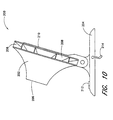
- the heat exchanger 28 is incorporated into a cooler, such as an ice chest 140.
- the ice chest 140 comprises a rectangular box that includes a base wall 144 and four side walls 146 extending upwardly therefrom.
- a lid 150 is pivotably mounted on the four side walls 146 in a well known manner to provide access to a storage space 152 defined by the walls of the ice chest 140.
- the walls of the ice chest are desirably insulated in a well known manner to maintain the temperature of the storage space 152.
- FIG 9 is a cross-sectional side view of the lid 150 of the ice chest 140.
- At least one heat exchangers 28 of the type described above with reference to Figures 1-6 is disposed within the lid 150.
- the heat exchanger 28 is connected to a power source (not shown), such as a battery of the proper voltage and power, and is configured to operate in a cooling mode such that it outputs a flow of cold air at the first fan 42, as described above.
- the heat exchanger 28 is rotatably mounted within the lid 150 such that the waste side of the heat exchanger 28 is positioned between top and bottom walls 156, 158, respectively, with an insulation member positioned to thermally separate the main and waste sides.
- the main side of the heat exchanger 28 is disposed immediately below the bottom wall 158.
- a cover unit 159 is positioned over the main side of the heat exchanger 28.
- the cover unit 159 includes a series of apertures to allow air to flow through the main side of the heat exchanger 28.
- the main side of the heat exchanger 28 is positioned within the storage space 152 of the ice chest 140 when the lid 150 is closed.
- the waste side of the heat exchanger 28 is disposed between the top and bottom wells 156 and 158 of the lid 150.
- An inlet 38 extends through the top wall 156 to allow air to flow into and out of the heat exchanger 28.
- the lid 150 is preferably filled within insulative material around heat exchanger 28.
- the heat exchanger 28 is powered in the cooling mode so that the first fan 42 generates a flow of cooled air within the storage space 152 when the lid 150 is closed. In this manner, the storage space 152 is maintained at a relatively cool temperature.
- the heated waste air is routed to the outside environment such as through an outlet in the top wall 156 of the lid 150. Any of a wide variety of articles, such as food, may be stored within the storage space 152.
- the fan unit 200 includes a housing 202 that is pivotably mounted to base 204.
- the housing 202 is substantially cylindrical shaped and includes a conditioned air outlet 206 and one or more waste air outlets 208 around the periphery of the housing 202.
- An air inlet 210 is located in the housing 200 opposite the conditioned air outlet 206.
- a control switch 212 and a power cord 214 are coupled to the base 204 for selectively powering the fan unit 200 and/or the thermoelectric element 232 in a well known manner.
- FIG 11 is a cross-sectional view of the fan unit 200.
- An annular duct 216 is disposed within the housing 202 and defines the conditioned air outlet 206.
- a second duct 218 defines the waste air outlets 208.
- a drive axle 220 is rotatably mounted within the housing so as to be axially-aligned with the conditioned air outlet 206.
- a motor 222 is drivingly coupled to the drive axle 220 via a drive belt 224.
- a rotor assembly 226 is mounted to the drive axle 220 so that the rotor assembly rotates with the drive axle 220.
- the rotor assembly 220 comprises a main fan 228 adjacent the conditioned air outlet 206 and an annular waste fan 230 on the side of the main fan 228 opposite the conditioned air outlet 206.
- a thermoelectric element 232 such as a Peltier heat exchanger, is interposed between the main and waste fans 228 and 230.
- the main fan 228 has a circumference that is less than or equal to the circumference of the conditioned air outlet 206 so that the main fan is configured to cause air to flow through the conditioned air outlet 206.
- the waste fan 230 is positioned so to communicate with the waste outlet 208.
- the main and waste fans 228 and 230 may comprise any type of device that is configured to produce an air flow upon rotation.
- the fans comprises flat discs having louvers 234 punched therethrough.
- the fans are preferably manufactured of a highly thermally conductive material.
- the motor 22 is powered through a power source (not shown) in a well known manner.
- the thermoelectric device 232 cools the main fan 228 and heats the waste fan 230 (or vice versa) in the manner described above with respect to the previous embodiments.
- the fans also rotate to produce a flow of conditioned and waste air through the conditioned air outlet 206 and the waste air outlet 208, respectively.
- the air may be routed to cool a desired location, such as beneath a desk. if desired, ducts, hoses and other devices may be connected to the outlets to further direct the flow of air therefrom.
- FIG 12 shows another embodiment of a heat exchanger comprising a fan unit 170 having a plurality of air flow generating members, such as blades 172, that rotate about an drive axle 174.
- a motor 176 is drivingly connected to the axle 174, either directly or indirectly, such as through a gear mechanism.
- the resistors may be embedded within the blades 172 or may be painted thereon, such as with adhesive.
- the resistors 180 are heated by applying an electrical current thereto and the axle 174 is rotated via the motor 176.
- the blades 172 generate an airflow, which is heated by the resistors through a convective process.
- the fan unit 170 is thereby used to generate a heated airflow.
- the rotors 42, 44 are shown cormected to the rotating shaft 52 by plate 51 located adjacent the first or upper wall 31.
- the interior cavity formed by the inner diameters of rotors 42, 44 are interconnected. It is believed possible to have the plate 51 contoured to the exterior shape of the top portion of motor 50 and then extend radially outward at about the plane containing the thermoelectric 46. That would place a physical separation between the air flows entering rotors 42 and 44.
- the above description refers primarily to the use of the method and apparatus in a vehicle seat. But the method and apparatus are equally applicable to other seats, including, but not limited to, theater seats, office seats, airplane seats, seats found in the home such as sofas and recliners, hospital seats for patients, hospital beds for bedridden patients, and wheelchairs.
- the method and apparatus is especially useful where a localized flow of conditioned air is desired.
- the present invention is not limited to air as other gases may be used with the present apparatus and method. Indeed, some gases, such as helium, have greater thermal conductivity than air and are desirable in certain applications, while other gasses such as oxygen, nitrogen or argon may be more desirable in other applications. A variety of gases and gas mixtures can be used as the particular application requires.
- liquids can be used with the present invention by applying appropriate liquid seals and insulators known in the art to keep the liquid circulating through the heat exchanger from making electrical contact with the thermoelectric device and any other electrical devices.
- liquids such as water and antifreeze are contemplated for use with the present method and apparatus, as are liquid metals such as liquid sodium.
- the particular liquid used will depend upon the application.
- the increased thermal conductivity achieved by passing the liquids over the rotating heat exchanger offer the possibility of increased heat conduction over less dense and less conductive gases. Whether a liquid or gas is most advantageous will vary with the particular application.
- the term "fluid" will be used to refer to a gas, a liquid or both.
- the rotating heat exchanger of the present invention has potential applicability to a wide variety of uses other than the seat, fan and cooler described herein.
- the method and apparatus of described herein are generally applicable to any situation where there is a desire to pump a thermally conditioned fluid. Such applications include constant temperature devices, as for example devices using a reference temperature as in a thermocouple assembly. Constant temperature baths for laboratory equipment and experiments is another exemplary application, as for instance growing bacteria cultures or cell cultures.
- the method and apparatus described herein are particularly useful where lower flow rates and/or smaller temperature changes are desired, but the invention is not so limited and may find application in situations requiring large flow rates and/or substantial temperature differences.
- a controlled stream of thermally conditioned fluid can be provided to maintain the temperature at a predetermined temperature, or to provide predetermined thermal conditions.
- the invention provides advantages where localized thermal control is desired, as in vehicle seats, waterbeds, aquariums, water coolers, and cooling of non-carbonated beverages such as wine and punch.
- the temperature is controlled to a fairly constant temperature, or controlled within a fairly narrow temperature range of less than about a 5 F variation above or below a predetermined temperature, and more typically within a 1-2 F variation on either side of a predetermined temperature.
- Such temperature control systems are known to those skilled in the art and their incorporation and use with the present method and apparatus are not described in detail herein.
- this device and method find particular application in situations where a fluid of differing temperature is desired at various times.
- the fan portion of the device may be operated with the thermoelectric heating or cooling aspects being activated only when desired to thermally condition the fluid flowing through the fan.
- a heated, cooled, or neutral temperature fluid can be provided by the same device and method.
Abstract
Description
- The present invention relates to a seat, such as an automobile seat, with a temperature controlled ventilation system.
- Modern automobile seats may be equipped with temperature control systems that allow the occupant to vary the temperature of the seat by flowing temperature-controlled air through the seat covering (see for instance WO-A-95/14899). One type of system comprises a seat having a heat transfer system mounted therein, such as a thermoelectric element configured to heat or cool air that is moved over the element using a separate fan unit that is also mounted within the seat. The conditioned air is distributed to the occupant by passing the air through the seat surface via a series of air ducts within the seat.
- The amount of space available within, below and around the seat for such temperature control systems is severely limited. In some cars, to save weight or increase passenger room, the seats are a few inches thick and abut the adjacent structure of the car, such as the floorboard or the back of the car. Further, automobile manufacturers are increasingly mounting various devices, such as electronic components or variable lumbar supports, within, below and around the seat. Additionally, the size of the seat, particularly the seat back, needs to be as small as possible to reduce the amount of cabin space consumed by the seat.
- Present temperature control systems are often too large to be mounted within, below or around vehicle seats. Conventional systems may have a squirrel cage fan five or six inches in diameter generating an air flow that passes through a duct to reach a heat exchanger that adjusts the temperature of the air. The heat exchanger is several inches wide and long, and at least an inch or so thick. From the heat exchanger the air is transported through ducts to the bottom of the seat cushion and to the back of the seat cushion. Such systems are bulky and difficult to fit underneath or inside car seats. Using thermoelectric devices to heat and cool the heat exchanger helps reduce the size of unit, but still requires a large volume for the combined heating and cooling system.
- The ducting used with these systems is also bulky and difficult to use if the duct must go from a seat bottom to a seat back that is allowed to pivot or rotate. These ducts not only use additional space within the seat, but also resist air flow and thus require a larger fan to provide the air flow, and the larger fan requires additional space or else runs at greater speeds and generates more noise. Noise is undesirable inside motor vehicles. Further, the ducting affects the temperature of the passing air and either heats cool air, or cools heated air, with the result of often requiring larger fans or heat exchangers.
- In light of these drawbacks, there is a need for a more compact and energy efficient heating and cooling system for automobile seats, and preferably a quieter system.
- The invention is defined in
claims 1 and 17. Preferred embodiments are defined in the dependent claims. - This device uses air flow generators, such as fan blades, that act as both a heat exchanger to transfer a thermal differential from a thermoelectric device and thereby condition air passing over the heat exchanger, and that act as an air pump. The heat exchanger rotates and provides aerodynamic and centrifugal force to the air passing through the heat exchanger to generate pressurized air for distribution, such as to the seat of a motor vehicle.
- In more detail, one embodiment of this device comprises at least one annular thermoelectric device (e.g., Peltier device) that, depending on the voltage applied, heats one surface and cools the opposing surface of the annular, thermoelectric device. Annular heat exchangers are placed in thermal communication with the opposing sides of the annular thermoelectric device by mounting them directly to the thermoelectric device so that each heat exchanger conducts the heat or cold from the surface of the device to which the heat exchanger is mounted. A resistive heating element may also be used to generate heat.
- In one embodiment, the annular heat exchangers are formed with radial slots extending through the heat exchanger, and form an annular cavity inside the heat exchangers when assembled. A motor nests inside the annular cavity formed on the inside of the assembled annular heat exchangers and annular, thermoelectric device, but spaced apart from the heat exchangers and thermoelectric device by an amount sufficient to allow air to flow along the exterior of the motor. The motor is drivingly connected to one of the heat exchangers and thermoelectric device to rotate them. The rotating heat exchangers act as a fan, drawing air into the annular cavity and expelling the air through the radial slots of the heat exchangers at a higher pressure. The volume of compressed air created is determined by the motor size, the fan blade shape, the rotational speed, and the overall geometry of the assembly.
- This arrangement allows the heat exchanger to be directly coupled to the thermoelectric device, and to act as a fan to not only generate the air pressure that distributes the conditioned air to passenger seats, but to condition the air as the air passes through the fan blades/heat exchanger. This reduces ducting and associated pressure losses, reduces the size of the system, and increases the overall efficiency of the system which in turn allows a reduction in fan size and power requirements. The compact arrangement allows the system to be placed underneath, and preferably inside most automobile seats, which further reduces ducting and associated pressure losses, and allows further reductions in motor size and power. The result of the various reductions is some combination of a smaller system volume, less power consumption, smaller size, and generation of less noise, than previously available.
- Advantageously, a seal separates the opposing sides of the rotating, annular heat exchangers to form a main, or supply side and a waste side. Air enters the assembly near the axis of rotation, which advantageously is aligned with the motor's rotational axis. The air exits radially or axially outward into a housing enclosing the majority of the annular fan/heat exchanger. An outlet in fluid communication with the main (or supply) side is in fluid communication with the seat of a passenger vehicle. An outlet in fluid communication with the waste side is also in fluid communication with an outlet at a location that will not degrade performance by allowing the waste air to be recirculated to the air entry portion. The thermoelectric creates a temperature differential between the supply side air and the waste side air. Layers of thermal insulation between the waste side and the supply side help maintain that temperature differential in portions of the assembly.
- Power is supplied to the thermoelectric device by brush and slip ring assemblies on the rotational axis of the motor. When appropriate voltages and currents are applied to the thermoelectric and the motor, a flow of either cold or hot air is provided to the supply side by the heat exchanger that conducts the temperature differential throughout the heat exchanger, and heats or cools the air passing over the heat exchanger/fan blades by conduction and convection. Voltage adjustments to the motor and thermoelectric control the pressure, temperature and flow rate.
- Advantageously, around a portion of the inside of the housing enclosing the annular fans, a wicking material is placed so that the material extends from the supply side to the waste side. If moisture condenses on one rotating fan, it is urged against the wicking material by centrifugal force from the rotating fan/heat exchanger. The wicking material absorbs the moisture, and transports the moisture to the opposing side where heated air evaporates the moisture and carries the moisture out of the system.
- There is thus advantageously provided a system for thermally conditioning a fluid passing over a rotating heat exchanger that also causes movement of the fluid. The system comprises an electronic device selected to convert electrical energy into thermal energy producing a temperature change in response to an electrical current being applied thereto. The electronic device is mounted to rotate about a rotational axis. A heat transfer device is placed in conductive thermal communication with the electronic device and is mounted to rotate about the axis. The heat transfer device has thermally radiating surfaces arranged to produce a fluid flow across the surfaces when rotated about the axis. The electronic device can comprise a heating resistor, or a thermoelectric device that can heat or cool the fluid. Advantageously, the heat transfer device comprises a first series of outwardly-extending thermally radiating surfaces connected to a first surface of the electric device. A second series of thermally radiating surfaces may be connected to an opposing, second surface of the thermoelectric device. In a preferred embodiment, the heat transfer device is contained in a housing having at least one outlet in fluid communication with a seat.
- The present invention also includes a means for producing a temperature change and a rotating supply side heat exchanger means for conducting the temperature change. The heat exchanger means further comprises fluid flow generating means for causing fluid to flow across said heat exchanger means. The fluid advantageously comprises a gas and the supply side heat exchanger means is advantageously in fluid communication with a seat to provide gas from the heat exchanger means to the seat.
- The apparatus also comprises a device for thermally conditioning a fluid having a first fan rotating about a rotational axis and having a first plurality of heat exchange surfaces in conductive thermal communication with an electronic device that converts electrical energy into a temperature change. The fan is advantageously enclosed in a housing that has an outlet.
- The present invention also comprises a method for thermally conditioning a fluid comprising the steps of producing a temperature change by an electronic device, conducting that temperature change to a heat exchanger having radiative surfaces, and rotating the radiative surfaces to cause fluid to flow across the radiative surfaces. Advantageously fluid from the heat exchanger is placed in thermal communication with a seat, and the fluid comprises a gas, preferably air. Alternatively, the thermally conditioned fluid is circulated to the interior of a chamber which may comprise a gas plenum, or circulated to a thermally insulated chamber provided with a closable opening to allow access to the interior of the chamber - such as a cooler.
- One method for producing a very compact form of the invention is to form a first heat exchanger having radiative surfaces aligned to allow the passage of air outward from an axis about which the heat exchanger rotates. The first heat exchanger is placed in conductive thermal communication with an electrical device that generates a temperature change when an electrical current is applied to the electrical device. The first heat exchanger is then rotated about the axis. Advantageously the electrical device comprises a thermoelectric device, and when placed inside a vehicle seat, provides a compact unit for ventilating the seat.
- The present invention further comprises means for producing a temperature differential and supply side heat exchanger means for conducting said temperature change, where the heat exchanger means further comprises fluid flow generating means for causing fluid to flow across said heat exchanger means. Advantageously, the supply side heat exchanger means is in fluid communication with a vehicle seat.
- A further version of the invention comprises a first fan rotating about a rotational axis and having a first plurality of heat exchange elements configured to generate a fluid flow through the heat exchange elements when rotated and in conductive thermal communication with an electronic device that converts electrical energy into a temperature change. The fan is advantageously enclosed in a housing that has an outlet in fluid communication with a fluid distribution system, and preferably the electronic device comprises a thermoelectric device.
- There is thus provided a system for thermally conditioning and pumping a fluid having use as a ventilation system for vehicle seats and other applications, in which an electrical resistor or thermoelectric device generates a temperature change that is conducted to a heat exchanger which forms an impeller to cause fluid to flow across the heat exchanger and thermally condition the fluid. The thermally conditioned fluid may be placed in thermal communication with a variety of objects, one of which is a vehicle seat to provide localized heating and cooling of a person sitting on the seat.
- The invention will now be described with reference to the drawings of an embodiment in which like number indicate like parts throughout, and which are intended to illustrate and not to limit the invention, and in which:
- Figure 1 is a perspective view of the heat exchanger of the present invention;
- Figure 2 is a perspective view of a rotary assembly of the heat exchanger of Figure 1;
- Figure 3 is a cross-sectional view of the heat exchanger along line 3-3 of Figure 1;
- Figure 4 is an enlarged cross-sectional view of a portion of the heat exchanger;
- Figure 5 is a top view of a rotor used with the heat exchanger;
- Figure 6 is a side view of the rotor of Figure 4;
- Figure 7 is a schematic view of a seat temperature control system incorporating the heat exchanger of the present invention;
- Figure 8 is a perspective view of a cooler box that incorporates the heat exchanger;
- Figure 9 is a cross-sectional side view of a lid of the cooler box of Figure 8;
- Figure 10 is a side view of a fan unit incorporating the heat exchanger of the present invention;
- Figure 11 is a side cross-sectional view of the fan unit of Figure 10; and
- Figure 12 is a perspective view of another embodiment of the heat exchanger.
-
- As shown in Figure 1, the
heat exchanger unit 28 of the present invention includes anouter housing 32 that defines an interior cavity 29 (Figure 3) in which a rotor assembly 30 (Figures 2 and 3) is rotatably mounted for producing a conditioned airflow into and out of theouter housing 32. While other shapes are suitable, theouter housing 32 is shown as resembling a generally flat disc with a first surface orfirst wall 31 that corresponds to an upper or top surface if thehousing 32 is placed in a seat bottom generally parallel to the ground. As used herein, up or upper will refer to a direction away from the ground. Down, lower or bottom will refer to a direction toward the ground. The relative direction of parts would alter if the entire orientation ofhousing 32 were changed, as may occur in actual use. Asecond wall 33, corresponding to a bottom surface, is opposite thefirst wall 31. The generally circular peripheries ofwalls side wall 35 to form an enclosure. - A
first outlet 34 extends outwardly from theside wall 35 adjacent the first orupper wall 31 of theouter housing 32. Asecond outlet 36 extends outwardly from theside wall 35 adjacent the second, orlower wall 33. Advantageously theoutlets housing 32. Theoutlets outlets housing 32, being the most likely relative positions. Theoutlets - A set of
apertures 38 are centrally formed in the first ortop wall 31 of theouter housing 32 to form afirst inlet 38 that communicates with theinterior cavity 29 formed and enclosed by theouter housing 32. Although not necessary, a second inlet 40 (Figure 3) may also be located on the second orbottom wall 33 of theouter housing 32 opposite thefirst inlet 38. - Referring to Figures 2 and 3, the
rotor assembly 30 generally comprises a plurality of components including an annularfirst rotor 42, an annularsecond rotor 44 disposed below thefirst rotor 42, and at least one annularthermoelectric device 46 interposed between, and in thermal communication with, thefirst rotor 42 and thesecond rotor 44. The thermoelectric device is also known as a Peltier device which comprises at least one pair of dissimilar materials connected electrically in series and thermally in parallel, and typically comprises a series of n-type and p-type semiconductor elements connected electrically in series and thermally in parallel. Depending on the direction of current passing through thethermoelectric device 46, one surface will be heated and the opposing surface will be cooled. Thethermoelectric device 46 generates a temperature differential that causes heat to transfer by conduction through therotors - The
rotors thermoelectric device 46 to conduct heat throughout therotors rotors thermoelectric device 46. Depending on the material and construction of therotors rotors rotors - The
rotors first rotor 42 and thesecond rotor 44. - In the illustrated embodiment, the
first rotor 42 is located on the supply side of the heat exchanger that supplies conditioned air to a user, and has an outer diameter that is smaller than the diameter of thesecond rotor 44. Thesecond rotor 44 is located on the waste side of the system and exhausts conditioned air, advantageously to a location that does not direct air to the supply side or that otherwise directs air to a location that could affect the user. Each of the components are axially aligned to rotate about a central axis aligned with a drive shaft oraxle 52 ofmotor 50. A disc-shapedconnector 51 having a central aperture is disposed on top of thefirst rotor 42 and themotor 50. Themotor 50 may be directly coupled to theaxle 52 or could be indirectly coupled, such as via a gear assembly. - The
connector 51 mechanically couples at least one of theshaft 52 ormotor 50 to thefirst rotor 42 so that themotor 50 is configured to rotatably drive thefirst rotor 42, thethermoelectric device 46, and thesecond rotor 44 about a common axis, as described in more detail below. The interior diameter ofrotors motor 50 to be inserted inside the space formed inside theannular rotors rotors - As shown in Figure 3, the
rotor assembly 30 is mounted within theouter housing 32 on adrive axle 52 that, in the illustrated embodiment, is journaled at opposing ends of the axle onshaft bearings 54 which are advantageously mounted towalls drive axle 52 of therotor assembly 30 is axially aligned with the first andsecond inlets outer housing 32. Theouter housing 32 could also be equipped with only a single inlet or with more than two inlets. - The plane of the
thermoelectric device 46 defines aboundary line 56 that divides theinterior cavity 29 into an upper portion orsupply side 58 and a lower portion orwaste side 60. Thefirst rotor 42 is located within the upper portion orsupply side 58 and thesecond rotor 44 is located within the lower portion orwaste side 60. - As best shown in Figure 3, the
rotor assembly 30 further includes a firstannular plate 63 that is disposed between a top edge of thethermoelectric device 46 and a bottom edge of thefirst rotor 42. A secondannular plate 65 is disposed between a bottom edge of thethermoelectric device 46 and the top of thesecond rotor 44 so that thethermoelectric device 46 is interposed between the first andsecond plates second plates first rotor 42 to thefirst plate 63 and thesecond rotor 44 to thesecond plate 65. Alternately,plates second rotors thermoelectric device 46. - An annular, disc-
like insulation member 64 of thermally insulated material extends from between therotors side walls 35. Advantageously themember 64 is positioned on top of the secondannular plate 65 adjacent the inner and outer periphery of thethermoelectric device 46 and is placed generally in the plane containingboundary line 56. Theinsulation member 64 is dimensioned to extend radially inward and outward from the thermoelectric device toward themotor 50 along theboundary line 56. Agap 66 is defined between the outer periphery of theinsulation disc 64 and the interior surface of theouter housing 32, with thegap 66 forming an air bearing to reduce the passage of air across thegap 66. - As shown in Figures 3 and 4, a thin and flexible
annular seal 70 of thermally insulated material is positioned so as to extend radially inward from the interior surface of theouter housing 32 generally along theboundary line 56. Theannular seal 70 is preferably sized so that it overlaps, but does not contact the adjacent surface of theinsulation member 64. Theannular seal 70 cooperates with theinsulation member 64 to define a labyrinth seal around the outer periphery of themember 64 that thermally insulates the upper portion orsupply side 58 of theinterior cavity 29 from the lower portion orwaste side 60 of theinterior cavity 29. Theinsulation member 64 andannular seal 70 prevent significant heat convection between the waste and main sides. Theannular seal 70 can be in the form of an air bearing that facilitates rotation of therotor assembly 30. Theinsulation member 64 may comprise any of a wide variety of heat resistant, thermally-insulative materials, such as expanded polypropylene. - With reference to Figure 4, at least a portion of the interior surface of the
housing 32 advantageously is coated with a wickingmaterial 78 that is adapted to absorb and conduct moisture. The wickingmaterial 78 extends between the upper andlower portions material 78 absorbs condensed moisture expelled by centrifugal force from whicheverrotor interior cavity 33 and in passages distributing the cooled air. Advantageously the wickingmaterial 78 absorbs enough moisture to prevent accumulation in the downstream passages in fluid communication with whicheverrotor - The
annular seal 70 must allow thewicking material 78 to pass. Thus, theseal 70 may be connected to an exterior surface of thematerial 78, may extend through the material 78 at intermittent locations, or may connect toside walls 35 at locates where thematerial 78 is absent. Thematerial 70 could also extend outside of theinterior cavity 33. - Referring to Figure 3, electrically-
conductive wires 80 are electrically coupled to thethermoelectric device 46 to provide an electrical potential thereto in a well known manner throughbrushes 84 that are in electrical communication with therotating drive axle 52. Because electrical current must be provided to thethermoelectric device 46 in a closed circuit, twobrushes 84 are in electrical communication with theaxle 52 and thermoelectric 46 through brush and slip-ring assemblies known in the art. Other electrical connections, such as, for example, an inductive coupling, can be devised given the present disclosure. - Figures 5 and 6 are top and side views, respectively, of the
first rotor 42. The structure of thesecond rotor 44 may be identical to that of thefirst rotor 42, although the respective dimensions may differ. The following more detailed description of thefirst rotor 42 is therefore equally applicable to that of thesecond rotor 44. Thefirst rotor 42 comprises a strip of corrugated metal having two connected ends so that thefirst rotor 42 is annular in shape. The corrugations or accordion-like pleats in thefirst rotor 42 form a series of radially-extending fins orblades 91 that define a series of radially-extending chambers orspaces 92 therebetween. Referring further to Figure 4, the width (i.e., the circumferential distance between adjacent fins 91) of thechambers 92 gradually increases moving radially outward from acenter point 90 of thefirst rotor 42. Eachrotor adjacent fins 91 is sufficiently wide at the inner radius R1 to allow air flow radially outward through therotor 42. - In the illustrated embodiment, the
blades 91 comprise generally flat walls that are connected and extend radially outward from acenter point 90 on the rotational axis of therotor 42. This design is not believed optimum from the aerodynamic viewpoint of moving the maximum volume of air through therotor 42 for a given rotational speed or rotor size. Theblades 91 may also be aerodynamically configured to provide various airflow profiles. For example, theblades 91 may be s-shaped, c-shaped, etc. Alternately, theblades 91 may comprise any type of straight or curved surface that produces an airflow when the surfaces are rotated. - The outer radius R2 preferably ranges from approximately 12 - 75 mm when incorporated into a temperature control system for a motor vehicle seat. The radial length of the
blade 91, the difference between the inner radius R1 and outer radius R2, is approximately 10-40 mm when theheat exchanger 28 is incorporated into a temperature control system for a motor vehicle seat, as described below with reference to Figure 7. Theblades 91 may have a height measured along the rotational axis, in the range of approximately 6-15 mm when used with car seats.Adjacent blades 91 are preferably spaced apart a distance of approximately 0.5-2 mm for a temperature control system for a seat. The thickness of theblades 91 when made of copper or aluminum is preferably in the range of approximately 0.05-0.2 mm when incorporated into a car seat. - In an alternative embodiment, the
thermoelectric device 46 is replaced by a resistive heating element which converts electrical energy into heat energy. This resistive heating element does not have the cooling capability of thethermoelectric device 46, but it does provided heat air which may have wider applicability in certain climates. - Referring to Figure 3, in operation, the
motor 50 rotate theaxle 52 by activating the power source through a control, such as a manual switch or a thermostatically controlled switch. The motor is in driving communication with thefirst rotor 42, thesecond rotor 44, and thethermoelectric device 46 so as to rotate those components about the rotational axis ofdrive axle 52. The rotation of thefirst rotor 42 creates a pressure differential that draws air into thesupply side 58 of theinterior cavity 29 through thefirst inlet 38. The air flows into thespaces 92 and radially outward across theblades 91 of thefirst rotor 42. The rotation of therotor 42 imparts centrifugal force to the air that propels the air radially outward fromrotor 42 so that the air travels out of thesupply side 58 of theinterior cavity 29 through thefirst outlet 34. - In a similar manner, the
second rotor 44 also rotates and draws are into the lower portion orwaste side 60 of theinterior cavity 29 through the second inlet 40 (or through eitherinlet spaces 92 between theblades 91 of thesecond rotor 44, radially outward acrossblades 91, and is propelled out of thewaste side 60 through thesecond outlet 36. Thedivider 64 keeps the air flows from intermingling, and because it is thermally insulated, maintains a temperature differential between thesupply side 58 andwaste side 60. - The
electrical wires 80 also supply an electrical current to thethermoelectric device 46, advantageously throughshaft 52, so that thethermoelectric device 46 heats therotor 42 and coolsrotor 44, or coolsrotor 42 and heatsrotor 44, depending on which direction the electrical current flows through thethermoelectric divide 46. As the air flows across theblades 91 of thefirst rotor 42 and thesecond rotor 44, the air is either heated or cooled through a convective process. That is, on the hot side of thethermoelectric device 46, heat is transferred to the air from the heated fins of the rotor as the air flows thereover. On the cooled side of the thermoelectric device, heat is absorbed from the air as the air passes over the cooled rotor to thereby cool the air. The heat exchanger thus produces heated air through one outlet and cooled air through the other outlet. The heated or cooled air is then directed to the appropriate location in the seat for heating or cooling the passenger seat. The air with the undesired temperature is vented to a location where it will not noticeably affect the vehicle passengers. Preferably, the waste air is vented to a location such that the waste air is not drawn back into theouter housing 32. - The
first rotor 42 and thesecond rotor 44 simultaneously function as fan units for generating an airflow at a predetermined pressure and also as heat exchangers for transferring heat to and from the airflow and maintaining the airflow at the desired temperature. By combining the heat exchanger function into the fan that generates the air flow, several advantages are achieved. By forming the heat exchanger into an annular fan and nesting the motor inside the heat exchanger/fan, space and weight savings are achieved. - Currently used systems are about 45 mm in height, which is too big for many motor vehicles. Newly designed systems are about 30 mm in height, but a great number of motor vehicles still have seats too small to accommodate such fans underneath or around the seat, and few can accommodate that size within the seat. Fan and
heat exchanger units 28 with a height below about 20-30 mm will accommodate a majority of automotive seats, and the present invention can allow such construction. Butsystems 28 of the present invention having a height of about 16 mm are believed possible, which is about half the height of the smallest systems currently available, and small enough to allow the use of the heating/cooling system inside a significant majority of seat bottoms and seat backs currently used in motor vehicles. - This height reduction represents the distance between
walls rotors blades 91 being a compromise between blade height, blade length, and diameter, and that area must be offset by the change in performance and rotational speed of the fan. Also,shorter rotors - Further, the design eliminates the interconnecting ducting between the fan and the heat exchanger, saving weight, size and pressure losses in the transmitted air. The small size also allows placement of heating and cooling systems directly in the seat bottoms and backs, further reducing the need for ducting, and especially reducing the need for ducting across the pivoted joints between seat bottoms and backs. The reduced ducting and its associated pressure losses and performance degradation, also allows the use of smaller fans, which use less energy and generate less noise.
- Moreover, the consolidation of several parts and functions allows a reduced manufacturing cost and an increase in efficiency of the system. The drag normally caused by passing the air over the heat exchanger is significantly reduced because the heat exchanger forms the fan blades that generate the air flow. Thus, savings of about 25% - 35% of the fan power are believed possible. Further, adequate heating and cooling of a motor vehicle seat are believed to use about 1000 watts less than the power needed to provide the same comfort level to a passenger using the heating and cooling system of a motor vehicle - which must heat and cool the entire passenger compartment rather than the localized environment of the seat on which the passenger sits.
- A further advantage is the reduction of noise because two small fans can be used. The
rotors rotors rotors - To further enhance the above advantages, in a further embodiment the
blades 91 may comprise a series of independent walls mounted on an annular plate where theblades 91 are contoured or curved to provide a preselected airflow profile when thefirst rotor 42 rotates, advantageously a profile that is more efficient than thestraight blades 91 described above while still conducting heat well and maintaining a low manufacturing cost. Further, theblades 91 as illustrated and described above are not optimized for minimizing noise, and noise reduction is an important consideration for equipment operating inside the passenger compartment of motor vehicles. A more refined design of theblades 91 could advantageously reduce noise. It is believed that the level of noise generated by rotation of therotors blades 91 increases. To accommodate the thermal transfer use of therotor blades 91, more blades are likely to be required then may be desirable for optimum performance if therotors rotors - The compact design also reduces the weight of the unit. As mentioned, the
blades 91 are preferably manufactured of a thermally conductive material, such as pure annealed aluminum, carbon, and copper, which are known to be highly thermally conductive materials. Other material may be used as scientific advances in conductive material are made. While copper is heavier than aluminum, its increased thermal conduction properties offer advantages and design options in configuring therotor blades 91 to perform both heat transfer and air movement functions. The blades preferably have a thermal conductivity rate of greater than about 12 w/m•°K. - The conditioned air that flows out of the first and
second outlets heat exchanger 28 is incorporated into a ventilation system for vehicle seats, such as for automobiles, as described below with reference to Figure 7. It will be appreciated that theheat exchanger 28 could also be used in other applications as well. - Referring to Figure 7, an automobile seat
temperature control system 112 comprises at least oneseat 114 and a pair ofheat exchangers heat exchangers 28") mounted therein. Theheat exchangers 28 are of the type described above with reference to Figures 1-6. In the illustrated embodiment, thefirst heat exchanger 28a is mounted within aseat bottom 118 and thesecond heat exchanger 28b is mounted within a seat back 120. The heat exchangers may also be mounted adjacent any portion of theseat 114, such as below or on the side of theseat 114. - The
seat 114 has a series ofchannels 116 for the passage of air. Anouter covering 117 of theseat 114 surrounds apadding layer 119 through which thechannels 116 extend. Theouter covering 117 is desirably perforated or air-permeable to allow air to flow therethrough from thechannels 116. Theseat 114 also includesseat bottom 118 and seat back 120 extending upwardly therefrom for supporting a human body in a sitting position. Theouter covering 117 may comprise any well known material for covering seats, such as perforated vinyl, cloth, perforated leather, etc. The padding layer of theseat 114 may comprise any well-known material for enhancing user comfort, such as reticulated foam. - With reference to Figure 7, the first outlet 34 (Figure 1) of the
first heat exchanger 28a is attached tochannels 116 that extend through the seat back 114. Thefirst outlet 34 of thesecond heat exchanger 28 is attached to thechannels 116 that extend through theseat bottom 118. Each of theheat exchangers 28 is electrically coupled to a power source via a control switch so that a user may selectively power the heat exchangers via the power switch. A control switch is also coupled to theheat exchangers 28 for reversing the polarity of the electrical current applied to theheat exchangers 28 in a well known manner. The control switch is used to switch theheat exchangers 28 between a heating and a cooling mode. In the heating mode, theheat exchangers 28 pump heated air into theseat 114. In the cooling mode, the heat exchangers pump cooled air into theseat 114. Theheat exchangers 28 may also be coupled to separate power and temperature controllers for providing independently-controlled conditioned airflow to the seat back 114 and theseat bottom 120. - A feedback control system including a temperature sensor, such as a thermocouple, may also be provided. The
system 112 may also be equipped with a control system for varying the speed of therotors - The
channels 116 may comprise a series of plastic ducts or pipes that are coupled to at least one of the first andsecond outlets heat exchangers 28 and disposed within theseat 114. Advantageously, the ducts may be formed by heat sealing the plastic foam of which the seat is made, or by coating the duct with a sealant to reduce air loss through the duct. The channels could also comprise air gaps within a permeable material, such as reticulated foam, that allow air to flow therethrough. Additionally, the channels may comprise any type of passage for the flow of air, such as ducts, pipes, small holes, etc. - Preferably, a
main duct 137 is connected to thefirst outlet 34 for routing the cooled or heated air to theseat 114surface 117 via thechannels 116. Awaste duct 138 is connected to at least thesecond outlet 36 for routing the unwanted waste air to the outside environment away from thepassenger occupying seat 114. - In operation, the power switch is activated to supply an electrical current to the
heat exchangers 28. As discussed above, thethermoelectric device 46 and the main andsecond rotors main ducts 137 and throughout theseat 114. The conditioned air flows out of thechannels 116 through the permeable outer covering 117 to thereby cool or heat the occupant of theseat 114. Desirably, the waste air is routed away from theseats 114 through thewaste ducts 138. - The
waste ducts 138 can advantageously vent below theseat bottom 118 because the heating and cooling system in the passenger compartment can produce typically over 20 times the amount of heat or cool air as is exhausted throughwaste duct 138. As long as thewaste ducts 138 do not vent directly on a passenger, toward a passenger, or on theinlets waste ducts 138. Awaste duct 138 connectingunit 28a located in theback portion 119 can vent below theseat bottom 118 without having a duct extend across the pivoted joint between thebottom portion 118 andbackrest 119. Because the airflow ofwaste duct 138 is downward toward theseat bottom 118, two aligned openings, one at the bottom ofback portion 119, and one in theseat bottom 118, are sufficient to convey the air to below theseat bottom 118. - As shown in Figure 8, in another embodiment, the
heat exchanger 28 is incorporated into a cooler, such as anice chest 140. In the illustrated embodiment, theice chest 140 comprises a rectangular box that includes abase wall 144 and fourside walls 146 extending upwardly therefrom. Alid 150 is pivotably mounted on the fourside walls 146 in a well known manner to provide access to astorage space 152 defined by the walls of theice chest 140. The walls of the ice chest are desirably insulated in a well known manner to maintain the temperature of thestorage space 152. - Figure 9 is a cross-sectional side view of the
lid 150 of theice chest 140. At least oneheat exchangers 28 of the type described above with reference to Figures 1-6 is disposed within thelid 150. Theheat exchanger 28 is connected to a power source (not shown), such as a battery of the proper voltage and power, and is configured to operate in a cooling mode such that it outputs a flow of cold air at thefirst fan 42, as described above. Theheat exchanger 28 is rotatably mounted within thelid 150 such that the waste side of theheat exchanger 28 is positioned between top andbottom walls heat exchanger 28 is disposed immediately below thebottom wall 158. A cover unit 159 is positioned over the main side of theheat exchanger 28. The cover unit 159 includes a series of apertures to allow air to flow through the main side of theheat exchanger 28. The main side of theheat exchanger 28 is positioned within thestorage space 152 of theice chest 140 when thelid 150 is closed. - The waste side of the
heat exchanger 28 is disposed between the top andbottom wells lid 150. Aninlet 38 extends through thetop wall 156 to allow air to flow into and out of theheat exchanger 28. Thelid 150 is preferably filled within insulative material aroundheat exchanger 28. - In operation, the
heat exchanger 28 is powered in the cooling mode so that thefirst fan 42 generates a flow of cooled air within thestorage space 152 when thelid 150 is closed. In this manner, thestorage space 152 is maintained at a relatively cool temperature. The heated waste air is routed to the outside environment such as through an outlet in thetop wall 156 of thelid 150. Any of a wide variety of articles, such as food, may be stored within thestorage space 152. - With reference to Figure 10, there is shown a
fan unit 200 that is configured to be mounted adjacent or within a standard desk. Thefan unit 200 includes ahousing 202 that is pivotably mounted tobase 204. Thehousing 202 is substantially cylindrical shaped and includes aconditioned air outlet 206 and one or morewaste air outlets 208 around the periphery of thehousing 202. Anair inlet 210 is located in thehousing 200 opposite theconditioned air outlet 206. Acontrol switch 212 and apower cord 214 are coupled to thebase 204 for selectively powering thefan unit 200 and/or thethermoelectric element 232 in a well known manner. - Figure 11 is a cross-sectional view of the
fan unit 200. Anannular duct 216 is disposed within thehousing 202 and defines the conditionedair outlet 206. Asecond duct 218 defines thewaste air outlets 208. Adrive axle 220 is rotatably mounted within the housing so as to be axially-aligned with theconditioned air outlet 206. In the illustrated embodiment, a motor 222 is drivingly coupled to thedrive axle 220 via adrive belt 224. Arotor assembly 226 is mounted to thedrive axle 220 so that the rotor assembly rotates with thedrive axle 220. - The
rotor assembly 220 comprises amain fan 228 adjacent theconditioned air outlet 206 and anannular waste fan 230 on the side of themain fan 228 opposite theconditioned air outlet 206. Athermoelectric element 232, such as a Peltier heat exchanger, is interposed between the main andwaste fans main fan 228 has a circumference that is less than or equal to the circumference of theconditioned air outlet 206 so that the main fan is configured to cause air to flow through theconditioned air outlet 206. Thewaste fan 230 is positioned so to communicate with thewaste outlet 208. The main andwaste fans discs having louvers 234 punched therethrough. The fans are preferably manufactured of a highly thermally conductive material. - In operation, the
motor 22 is powered through a power source (not shown) in a well known manner. Thethermoelectric device 232 cools themain fan 228 and heats the waste fan 230 (or vice versa) in the manner described above with respect to the previous embodiments. The fans also rotate to produce a flow of conditioned and waste air through theconditioned air outlet 206 and thewaste air outlet 208, respectively. The air may be routed to cool a desired location, such as beneath a desk. if desired, ducts, hoses and other devices may be connected to the outlets to further direct the flow of air therefrom. - Figure 12 shows another embodiment of a heat exchanger comprising a
fan unit 170 having a plurality of air flow generating members, such asblades 172, that rotate about andrive axle 174. Amotor 176 is drivingly connected to theaxle 174, either directly or indirectly, such as through a gear mechanism. One or more electrical heat generating devices, such as electrical resistors 180, ere mounted on theblades 172. The resistors may be embedded within theblades 172 or may be painted thereon, such as with adhesive. - In operation, the resistors 180 are heated by applying an electrical current thereto and the
axle 174 is rotated via themotor 176. Theblades 172 generate an airflow, which is heated by the resistors through a convective process. Thefan unit 170 is thereby used to generate a heated airflow. - Given the above disclosure, other variations of this invention will be known to those skilled in the art. For example, the
rotors rotating shaft 52 byplate 51 located adjacent the first orupper wall 31. In this configuration the interior cavity formed by the inner diameters ofrotors plate 51 contoured to the exterior shape of the top portion ofmotor 50 and then extend radially outward at about the plane containing the thermoelectric 46. That would place a physical separation between the air flows enteringrotors motor 50 with a radial flange extending radially outward at about the plane containingboundary line 56, with themotor 50 rotating, and thus provide a physical separation between the air flows entering therotor - The above description refers primarily to the use of the method and apparatus in a vehicle seat. But the method and apparatus are equally applicable to other seats, including, but not limited to, theater seats, office seats, airplane seats, seats found in the home such as sofas and recliners, hospital seats for patients, hospital beds for bedridden patients, and wheelchairs. The method and apparatus is especially useful where a localized flow of conditioned air is desired.
- The above description refers to the passage of air through the heat exchangers, but the present invention is not limited to air as other gases may be used with the present apparatus and method. Indeed, some gases, such as helium, have greater thermal conductivity than air and are desirable in certain applications, while other gasses such as oxygen, nitrogen or argon may be more desirable in other applications. A variety of gases and gas mixtures can be used as the particular application requires.
- Further, liquids can be used with the present invention by applying appropriate liquid seals and insulators known in the art to keep the liquid circulating through the heat exchanger from making electrical contact with the thermoelectric device and any other electrical devices. Thus, liquids such as water and antifreeze are contemplated for use with the present method and apparatus, as are liquid metals such as liquid sodium. The particular liquid used will depend upon the application. The increased thermal conductivity achieved by passing the liquids over the rotating heat exchanger offer the possibility of increased heat conduction over less dense and less conductive gases. Whether a liquid or gas is most advantageous will vary with the particular application. For ease of reference, the term "fluid" will be used to refer to a gas, a liquid or both.
- Because the temperature change available from a thermoelectric can be significant, the rotating heat exchanger of the present invention has potential applicability to a wide variety of uses other than the seat, fan and cooler described herein. The method and apparatus of described herein are generally applicable to any situation where there is a desire to pump a thermally conditioned fluid. Such applications include constant temperature devices, as for example devices using a reference temperature as in a thermocouple assembly. Constant temperature baths for laboratory equipment and experiments is another exemplary application, as for instance growing bacteria cultures or cell cultures. The method and apparatus described herein are particularly useful where lower flow rates and/or smaller temperature changes are desired, but the invention is not so limited and may find application in situations requiring large flow rates and/or substantial temperature differences.
- By placing a temperature sensor at a predetermined location, whether on the heat exchanger, the rotating fan, upstream or downstream of the heat exchanger, and electronically controlling the thermoelectric and the fan rotation, a controlled stream of thermally conditioned fluid can be provided to maintain the temperature at a predetermined temperature, or to provide predetermined thermal conditions. Thus, the invention provides advantages where localized thermal control is desired, as in vehicle seats, waterbeds, aquariums, water coolers, and cooling of non-carbonated beverages such as wine and punch. In these applications the temperature is controlled to a fairly constant temperature, or controlled within a fairly narrow temperature range of less than about a 5 F variation above or below a predetermined temperature, and more typically within a 1-2 F variation on either side of a predetermined temperature. Such temperature control systems are known to those skilled in the art and their incorporation and use with the present method and apparatus are not described in detail herein.
- Further, this device and method find particular application in situations where a fluid of differing temperature is desired at various times. The fan portion of the device may be operated with the thermoelectric heating or cooling aspects being activated only when desired to thermally condition the fluid flowing through the fan. Thus a heated, cooled, or neutral temperature fluid can be provided by the same device and method.
Claims (18)
- A seat (114) with a temperature controlled ventilation system, comprising:a supply side, annular heat exchanger (42) forming a hole (38) therein about an axis of rotation and configured to allow air to pass outward from said axis of rotation;a waste side, annular heat exchanger (44) forming a hole (40) therein about said axis of rotation and configured to allow air to pass outward from said axis of rotation;a thermoelectric device (46) having first and second opposing surfaces that generate elevated temperatures on one of the first and second surfaces and reduced temperatures on the other of the first and second opposing surfaces depending on the electrical potential applied to the thermoelectric device (46), one opposing surface being connected to and in thermal communication with the supply side heat exchanger (42) and the other opposing surface being connected to and in thermal communication with the waste side heat exchanger (44);a motor (50) drivingly connected to at least one of the heat exchangers or thermoelectric device (42, 44 or 46) to rotate at least one of the heat exchangers (42 and 44) or the thermoelectric device (46) about the axis of rotation to cause air to enter at least one of the holes (38 or 40) along the axis of rotation and pass outward through the heat exchanger (42 or 44);a housing (32) containing at least the supply side heat exchanger (42) and forming an outlet (34) through which air exits after passing through the supply heat exchanger (42); anda seat (44) having a surface against which a person rests, the surface having passages therethrough in at least a portion of the surface where the person rests, the surface being in fluid communication with the outlet (34) of the supply heat exchanger (42), the heat exchanger and motor rotation cooperating so that air from the heat exchanger (42) is forced through the surface of said seat to provide conditioned air in the area where said person rests against the surface during use of the seat.
- Apparatus according to Claim 1, characterised by a wicking material (78) connected to at least a portion of the housing (32) and having a first portion in contact with air exiting the supply side heat exchanger (42) and having a second portion in contact with air exiting the waste side heat exchanger (44) so that if one of the heat exchangers (42 or 44) generates moisture the wicking material (78) conducts the moisture away from the heat exchanger (42 or 44) producing the moisture.
- Apparatus according to Claim 1 or to Claim 2, characterised in that the combined height of the heat exchangers (42, 44) and thermoelectric device (46) is less than about 30 mm when measured along the rotational axis.
- Apparatus according to any one of Claims 1 to 3, characterised in that the housing (32) encloses both heat exchangers (42, 44) and further comprising an insulating layer (64) between the first and second heat exchangers (42, 44) that extends radially outward toward the housing (32) to form an insulated barrier between the supply and waste heat exchangers (42 and 44).
- Apparatus according to Claim 4, characterised by a non-contacting labyrinth seal (70) formed between a periphery of the insulating layer (64) and a portion of the housing (32) enclosing a periphery of the heat exchangers (42, 44) to inhibit air flow between the heat exchangers (42, 44).
- Apparatus according to any preceding claim, characterised in that the motor nests in at least one of said holes (38, 40) in the heat exchangers (42, 44).
- Apparatus according to Claim 1, characterised in that the thermoelectric device (46) converts electrical energy into thermal energy producing a temperature change in response to an electrical current being applied thereto, the thermoelectric device (46) comprising a circular disk having the first and second opposing surfaces and being mounted to rotate about a rotational axis through a centre of the disk, and
wherein at least one of the supply side and waste side heat exchangers (42 or 44) has an inner diameter and an outer diameter, is in conductive thermal communication with the thermoelectric device (46), and is mounted on one of the disk surfaces to rotate about the axis, said heat exchangers (42 or 44) having thermally radiating surfaces arranged to produce a fluid flow across the surfaces outward from the rotational axis when rotated about the axis, said heat exchangers (42 or 44) having a height measured along the rotational axis and diameters measured along an axis orthogonal to the rotational axis with the distance between the inner and outer diameters being greater than the height. - Apparatus according to Claim 7, characterised in that the heat exchanger comprises a first series of thermally radiating surfaces connected to the first surface of the thermoelectric device (46) and wherein the first series of radiating surfaces are aligned with a plurality of axes orthogonal to the rotational axis, and a second series of thermally radiating surfaces connected to the second surface of the thermoelectric device (46) and wherein the second series of radiating surfaces are aligned with a plurality of axes orthogonal to the rotational axis, the first and second series of thermally radiating surfaces having different radiative areas.
- Apparatus according to Claim 8, characterised in that the housing has at least one outlet in fluid communication with the seat and has an inlet configured to provide air to the inner diameter of the annular thermally radiating surfaces along the rotational axis.
- Apparatus according to any one of Claims 7 to 9, characterised in that at least some of the heat exchange surfaces form substantially flat sheets extending outward from the rotational axis and define a series of spaces between the sheets.
- Apparatus according to any one of Claims 7 to 10, characterised in that at least one of the first and second series of heat exchange surfaces are separated by a distance in the range of from 0.5 to 2 mm.
- Apparatus according to Claim 1, characterised in that the supply side and waste side heat exchangers (42 and 44) comprise first and second fans,
the first fan rotating about the rotational axis and having a first plurality of heat exchange surfaces in conductive thermal communication with the thermoelectric device (46), the second fan (44) rotating about the rotational axis and having a second plurality of heat exchange surfaces in conductive thermal communication with a second side of the thermoelectric device (46), the first and second plurality of heat exchange surfaces conducting a temperature change from said first and second sides of the thermoelectric device (46), the first and second fans (42 and 44) being enclosed in the housing (32) and comprising annular structures with differing outer diameters such that the first fan (42) extends from the thermoelectric device (46) towards the rotational axis while the second fan (44) extends from the thermoelectric device (46) away from the rotational axis, each of the fans (42 and 44) having a height along the rotational axis that is smaller than the diameter measured orthogonal to the rotational axis. - Apparatus according to Claim 1, characterised in that the seat (114) comprises a fluid distribution system in fluid communication with the seat (114), and in that the housing outlet (34) is in fluid communication with the fluid distribution system.
- Apparatus according to Claim 13, characterised in that the outlet (34) from the supply side heat exchanger (42) is in fluid communication with the interior of an enclosed and insulated portable chamber (52), and fluid from the waste side heat exchanger (44) is exhausted outside the chamber (152).
- Apparatus according to Claim 14, characterised in that the chamber (152) comprises a closable opening configured to allow access to the interior of the chamber (152).
- Apparatus according to any one of Claims 13 to 15, characterised in that the supply side and waste side heat exchangers (42, 44) and the thermoelectric device (46) rotate about the axis of rotation, causing fluid to enter at least one of the holes in the supply side and waste side heat exchangers and pass outward through the heat exchanger.
- A method for providing temperature controlled ventilation to a seat (114) having a seat surface, comprising the steps of:forming a supply side heat exchanger (42) rotating about an axis of rotation and configuring the heat exchanger (42) to allow fluid to pass therethrough, the supply side heat exchanger (42) having a first height along the rotational axis and a first diameter along an axis orthogonal to the rotational axis, with the first height being selected to be less than the first diameter;forming a waste side heat exchanger (44) rotating about said axis of rotation and configuring the waste side heat exchanger (44) to allow fluid to pass therethrough, the waste side heat exchanger (44) having a second height along the rotational axis and a second diameter along an axis orthogonal to the rotational axis, with the second height being selected to be less than the second diameter and sized to fit within or under a seat, and;providing a thermoelectric device (46) having opposing surfaces that generate elevated temperatures on one surface and reduced temperatures on the opposing surface depending on the electrical potential applied to the thermoelectric device, and conductively connecting one opposing surface of the thermoelectric device (46) to the supply side heat exchanger (42) and conductively connecting the other opposing surface to the waste side heat exchanger (44);causing relative rotation between the heat exchangers and thermoelectric device (42, 44, 46) about the axis of rotation to cause fluid to pass through the heat exchangers (42 and 44);enclosing the supply heat exchanger (42) and forming an outlet (34) through which fluid exits after passing through the supply heat exchanger (42); andplacing the seat surface in fluid communication with the outlet (34) of the supply heat exchanger.
- A method according to Claim 17, characterised by the steps of enclosing both heat exchangers (42 and 44) and insulating the first and second heat exchangers (42, 44) from each other and forming a non-contacting labyrinth seal between the heat exchangers (42, 44) to inhibit air flow between the heat exchangers (42, 44).
Priority Applications (1)
| Application Number | Priority Date | Filing Date | Title |
|---|---|---|---|
| EP04006634A EP1429089A3 (en) | 1998-05-12 | 1999-05-12 | Thermoelectric heat exchanger |
Applications Claiming Priority (3)
| Application Number | Priority Date | Filing Date | Title |
|---|---|---|---|
| US09/076,518 US6119463A (en) | 1998-05-12 | 1998-05-12 | Thermoelectric heat exchanger |
| US76518 | 1998-05-12 | ||
| PCT/US1999/010333 WO1999058907A1 (en) | 1998-05-12 | 1999-05-12 | Thermoelectric heat exchanger |
Related Child Applications (1)
| Application Number | Title | Priority Date | Filing Date |
|---|---|---|---|
| EP04006634A Division EP1429089A3 (en) | 1998-05-12 | 1999-05-12 | Thermoelectric heat exchanger |
Publications (2)
| Publication Number | Publication Date |
|---|---|
| EP1076797A1 EP1076797A1 (en) | 2001-02-21 |
| EP1076797B1 true EP1076797B1 (en) | 2004-05-12 |
Family
ID=22132523
Family Applications (2)
| Application Number | Title | Priority Date | Filing Date |
|---|---|---|---|
| EP99925590A Expired - Lifetime EP1076797B1 (en) | 1998-05-12 | 1999-05-12 | Seat with thermoelectric heat exchanger |
| EP04006634A Withdrawn EP1429089A3 (en) | 1998-05-12 | 1999-05-12 | Thermoelectric heat exchanger |
Family Applications After (1)
| Application Number | Title | Priority Date | Filing Date |
|---|---|---|---|
| EP04006634A Withdrawn EP1429089A3 (en) | 1998-05-12 | 1999-05-12 | Thermoelectric heat exchanger |
Country Status (9)
| Country | Link |
|---|---|
| US (5) | US6119463A (en) |
| EP (2) | EP1076797B1 (en) |
| JP (1) | JP3863371B2 (en) |
| CN (1) | CN1125298C (en) |
| AT (1) | ATE266847T1 (en) |
| AU (1) | AU4184199A (en) |
| DE (1) | DE69917254T2 (en) |
| ES (1) | ES2217759T3 (en) |
| WO (1) | WO1999058907A1 (en) |
Families Citing this family (228)
| Publication number | Priority date | Publication date | Assignee | Title |
|---|---|---|---|---|
| US6119463A (en) * | 1998-05-12 | 2000-09-19 | Amerigon | Thermoelectric heat exchanger |
| US6606866B2 (en) * | 1998-05-12 | 2003-08-19 | Amerigon Inc. | Thermoelectric heat exchanger |
| AU2001254385A1 (en) * | 2000-02-08 | 2001-08-20 | Stefan Glasa | Compact temperature-control system |
| US6295820B1 (en) * | 2000-03-14 | 2001-10-02 | Delta T, Llc | Fruit chiller |
| US7668362B2 (en) * | 2000-05-03 | 2010-02-23 | Aperio Technologies, Inc. | System and method for assessing virtual slide image quality |
| KR100442237B1 (en) * | 2000-12-29 | 2004-07-30 | 엘지전자 주식회사 | Thermoelectric cooler |
| US6672076B2 (en) * | 2001-02-09 | 2004-01-06 | Bsst Llc | Efficiency thermoelectrics utilizing convective heat flow |
| US7946120B2 (en) | 2001-02-09 | 2011-05-24 | Bsst, Llc | High capacity thermoelectric temperature control system |
| US7942010B2 (en) | 2001-02-09 | 2011-05-17 | Bsst, Llc | Thermoelectric power generating systems utilizing segmented thermoelectric elements |
| US7231772B2 (en) * | 2001-02-09 | 2007-06-19 | Bsst Llc. | Compact, high-efficiency thermoelectric systems |
| US6637210B2 (en) * | 2001-02-09 | 2003-10-28 | Bsst Llc | Thermoelectric transient cooling and heating systems |
| US6959555B2 (en) * | 2001-02-09 | 2005-11-01 | Bsst Llc | High power density thermoelectric systems |
| US6580025B2 (en) * | 2001-08-03 | 2003-06-17 | The Boeing Company | Apparatus and methods for thermoelectric heating and cooling |
| US7426835B2 (en) | 2001-08-07 | 2008-09-23 | Bsst, Llc | Thermoelectric personal environment appliance |
| US6571862B1 (en) * | 2002-06-25 | 2003-06-03 | Waffer Technology Corp. | Heat dissipating fin |
| US6893086B2 (en) * | 2002-07-03 | 2005-05-17 | W.E.T. Automotive Systems Ltd. | Automotive vehicle seat insert |
| US6857697B2 (en) * | 2002-08-29 | 2005-02-22 | W.E.T. Automotive Systems Ag | Automotive vehicle seating comfort system |
| US6779348B2 (en) | 2002-11-04 | 2004-08-24 | Tandis, Inc. | Thermoelectrically controlled blower |
| WO2005061972A1 (en) * | 2002-12-06 | 2005-07-07 | Nanocoolers, Inc. | Cooling of electronics by electrically conducting fluids |
| DE10259648B4 (en) * | 2002-12-18 | 2006-01-26 | W.E.T. Automotive Systems Ag | Air-conditioned seat and air conditioning device for a ventilated seat |
| US6935122B2 (en) * | 2003-03-18 | 2005-08-30 | Chiu Kuang Hsing Co., Ltd. | Air feeding apparatus |
| US20050056026A1 (en) * | 2003-09-16 | 2005-03-17 | Sundhar Shaam Periyapatna | Personal cooling system |
| US7274007B2 (en) | 2003-09-25 | 2007-09-25 | W.E.T. Automotive Systems Ltd. | Control system for operating automotive vehicle components |
| US7356912B2 (en) * | 2003-09-25 | 2008-04-15 | W.E.T. Automotive Systems, Ltd. | Method for ventilating a seat |
| US7425034B2 (en) * | 2003-10-17 | 2008-09-16 | W.E.T. Automotive Systems Ag | Automotive vehicle seat having a comfort system |
| US7370911B2 (en) * | 2003-10-17 | 2008-05-13 | W.E.T. Automotive Systems, Ag | Automotive vehicle seat insert |
| EP1675747B2 (en) | 2003-10-17 | 2017-03-29 | W.E.T. Automotive Systems Ag | Automotive vehicle seat insert |
| US7461892B2 (en) | 2003-12-01 | 2008-12-09 | W.E.T. Automotive Systems, A.C. | Valve layer for a seat |
| US7638705B2 (en) * | 2003-12-11 | 2009-12-29 | Nextreme Thermal Solutions, Inc. | Thermoelectric generators for solar conversion and related systems and methods |
| US20100257871A1 (en) * | 2003-12-11 | 2010-10-14 | Rama Venkatasubramanian | Thin film thermoelectric devices for power conversion and cooling |
| JP2007535803A (en) * | 2003-12-11 | 2007-12-06 | ネクストリーム・サーマル・ソリューションズ | Thin film thermoelectric devices for power conversion and cooling |
| US20050150536A1 (en) * | 2004-01-13 | 2005-07-14 | Nanocoolers, Inc. | Method for forming a monolithic thin-film thermoelectric device including complementary thermoelectric materials |
| US20050150537A1 (en) * | 2004-01-13 | 2005-07-14 | Nanocoolers Inc. | Thermoelectric devices |
| US20050150539A1 (en) * | 2004-01-13 | 2005-07-14 | Nanocoolers, Inc. | Monolithic thin-film thermoelectric device including complementary thermoelectric materials |
| US20050160752A1 (en) * | 2004-01-23 | 2005-07-28 | Nanocoolers, Inc. | Apparatus and methodology for cooling of high power density devices by electrically conducting fluids |
| US20050161193A1 (en) * | 2004-01-23 | 2005-07-28 | Mckenzie Chris | Seat heating and cooling system |
| US7108094B2 (en) * | 2004-02-06 | 2006-09-19 | Jerome Daniels | Mobile water device |
| US7380586B2 (en) | 2004-05-10 | 2008-06-03 | Bsst Llc | Climate control system for hybrid vehicles using thermoelectric devices |
| US7238101B2 (en) * | 2004-05-20 | 2007-07-03 | Delphi Technologies, Inc. | Thermally conditioned vehicle seat |
| US7114771B2 (en) * | 2004-05-25 | 2006-10-03 | Amerigon, Inc. | Climate controlled seat |
| US20050278863A1 (en) * | 2004-06-22 | 2005-12-22 | Riverpark Incorporated | Comfort product |
| US7059137B2 (en) * | 2004-09-07 | 2006-06-13 | Childress William H | Portable thermoelectric cooling and heating device |
| US20060075758A1 (en) | 2004-10-07 | 2006-04-13 | Tigerone Development, Llc; | Air-conditioning and heating system utilizing thermo-electric solid state devices |
| US20060076046A1 (en) * | 2004-10-08 | 2006-04-13 | Nanocoolers, Inc. | Thermoelectric device structure and apparatus incorporating same |
| US20070262621A1 (en) * | 2004-10-25 | 2007-11-15 | Hanh Dong | Apparatus for providing fluid through a vehicle seat |
| US20060087160A1 (en) * | 2004-10-25 | 2006-04-27 | Hanh Dong | Apparatus for providing fluid through a vehicle seat |
| US20060158011A1 (en) * | 2004-11-02 | 2006-07-20 | W.E.T. Automotive Systems Ag | Molded layer for a seat insert |
| US7587901B2 (en) * | 2004-12-20 | 2009-09-15 | Amerigon Incorporated | Control system for thermal module in vehicle |
| US7475551B2 (en) | 2004-12-23 | 2009-01-13 | Nanocoolers, Inc. | System employing temporal integration of thermoelectric action |
| US7296417B2 (en) * | 2004-12-23 | 2007-11-20 | Nanocoolers, Inc. | Thermoelectric configuration employing thermal transfer fluid flow(s) with recuperator |
| US7293416B2 (en) * | 2004-12-23 | 2007-11-13 | Nanocoolers, Inc. | Counterflow thermoelectric configuration employing thermal transfer fluid in closed cycle |
| US20060137099A1 (en) * | 2004-12-28 | 2006-06-29 | Steve Feher | Convective cushion with positive coefficient of resistance heating mode |
| US20060150657A1 (en) * | 2005-01-10 | 2006-07-13 | Caterpillar Inc. | Thermoelectric enhanced HVAC system and method |
| JP4926078B2 (en) * | 2005-02-07 | 2012-05-09 | エル アンド ピー プロパティ マネジメント カンパニー | Automotive ventilation, temperature control and ergonomic comfort system |
| KR100640824B1 (en) * | 2005-02-15 | 2006-11-06 | 엘지전자 주식회사 | air conditioning system and apparatus for raising air pressure and controlling method |
| US7827805B2 (en) * | 2005-03-23 | 2010-11-09 | Amerigon Incorporated | Seat climate control system |
| US20060214480A1 (en) * | 2005-03-23 | 2006-09-28 | John Terech | Vehicle seat with thermal elements |
| US7743614B2 (en) | 2005-04-08 | 2010-06-29 | Bsst Llc | Thermoelectric-based heating and cooling system |
| DE102005018445B3 (en) * | 2005-04-20 | 2006-06-29 | W.E.T. Automotive Systems Ag | Air conditioning device for e.g. vehicle seat has air-conditioning zones, which are connected to recess by connecting device whereby recess allows the air to pass through it partially in transverse direction inspite of cover |
| WO2006124835A1 (en) * | 2005-05-16 | 2006-11-23 | Amerigon, Inc. | Ventilated headrest |
| US8039726B2 (en) * | 2005-05-26 | 2011-10-18 | General Electric Company | Thermal transfer and power generation devices and methods of making the same |
| EP2282357B1 (en) | 2005-06-28 | 2015-12-02 | Gentherm Incorporated | Thermoelectric power generator for variable thermal power source |
| US8783397B2 (en) | 2005-07-19 | 2014-07-22 | Bsst Llc | Energy management system for a hybrid-electric vehicle |
| US7478869B2 (en) | 2005-08-19 | 2009-01-20 | W.E.T. Automotive Systems, Ag | Automotive vehicle seat insert |
| US7331183B2 (en) * | 2005-10-03 | 2008-02-19 | The United States Of America As Represented By The Secretary Of The Navy | Personal portable environmental control system |
| ATE547285T1 (en) | 2006-01-30 | 2012-03-15 | Amerigon Inc | COOLING SYSTEM FOR A CONTAINER IN A VEHICLE |
| GB2435320B (en) * | 2006-02-17 | 2008-10-08 | Richards Morphy N I Ltd | A device for temperature conditioning an air supply |
| US20070200398A1 (en) * | 2006-02-28 | 2007-08-30 | Scott Richard Wolas | Climate controlled seat |
| US7870745B2 (en) | 2006-03-16 | 2011-01-18 | Bsst Llc | Thermoelectric device efficiency enhancement using dynamic feedback |
| US7591507B2 (en) | 2006-04-13 | 2009-09-22 | Amerigon Incorporated | Tie strap for climate controlled seat |
| US8232091B2 (en) * | 2006-05-17 | 2012-07-31 | California Institute Of Technology | Thermal cycling system |
| KR100768851B1 (en) * | 2006-05-19 | 2007-10-22 | 엘지전자 주식회사 | Refrigerator |
| US8539624B2 (en) | 2006-05-31 | 2013-09-24 | Gentherm Incorporated | Structure based fluid distribution system |
| TWI321724B (en) * | 2006-08-01 | 2010-03-11 | Asustek Comp Inc | Fluid providing module and electronic device using the same |
| US20100155018A1 (en) | 2008-12-19 | 2010-06-24 | Lakhi Nandlal Goenka | Hvac system for a hybrid vehicle |
| US7779639B2 (en) | 2006-08-02 | 2010-08-24 | Bsst Llc | HVAC system for hybrid vehicles using thermoelectric devices |
| US7788933B2 (en) * | 2006-08-02 | 2010-09-07 | Bsst Llc | Heat exchanger tube having integrated thermoelectric devices |
| US8222511B2 (en) | 2006-08-03 | 2012-07-17 | Gentherm | Thermoelectric device |
| DE102006046114B4 (en) * | 2006-09-28 | 2012-02-02 | Airbus Operations Gmbh | Cooling arrangement for cooling a heat body for an aircraft |
| US7708338B2 (en) | 2006-10-10 | 2010-05-04 | Amerigon Incorporated | Ventilation system for seat |
| US20080087316A1 (en) | 2006-10-12 | 2008-04-17 | Masa Inaba | Thermoelectric device with internal sensor |
| EP2567637B1 (en) | 2006-10-13 | 2014-08-06 | Gentherm Incorporated | Air conditioning bed |
| US20080089027A1 (en) * | 2006-10-16 | 2008-04-17 | Nai-Ko Ying | Cooling Fan |
| WO2008057962A2 (en) * | 2006-11-01 | 2008-05-15 | Amerigon Incorporated | Chair with air conditioning device |
| DE102007027828A1 (en) * | 2006-11-14 | 2008-05-15 | Proseat Gmbh & Co.Kg | Module for cushioned object e.g. vehicle seat, has switching device partially corresponding with switching device of bolster unit, and cover covering bolster unit, where module and/or component part are foamed in carrier |
| US7640754B2 (en) | 2006-12-14 | 2010-01-05 | Amerigon Incorporated | Insert duct piece for thermal electric module |
| US20080164733A1 (en) * | 2007-01-08 | 2008-07-10 | Giffin Steven C | Clamp for climate control device |
| JP5485701B2 (en) | 2007-01-10 | 2014-05-07 | ジェンサーム インコーポレイティド | Thermoelectric element |
| US8143554B2 (en) | 2007-03-16 | 2012-03-27 | Amerigon Incorporated | Air warmer |
| CN101720414B (en) | 2007-05-25 | 2015-01-21 | Bsst有限责任公司 | System and method for distributed thermoelectric heating and colling |
| US8286696B2 (en) * | 2007-06-22 | 2012-10-16 | The Boeing Company | Mechanically actuated thermal switch |
| US20090000031A1 (en) * | 2007-06-29 | 2009-01-01 | Steve Feher | Multiple convective cushion seating and sleeping systems and methods |
| US20090033130A1 (en) * | 2007-07-02 | 2009-02-05 | David Marquette | Fluid delivery systems for climate controlled seats |
| US9105809B2 (en) | 2007-07-23 | 2015-08-11 | Gentherm Incorporated | Segmented thermoelectric device |
| CN101808839B (en) * | 2007-07-23 | 2012-09-19 | 阿美里根公司 | Radial thermoelectric device assembly |
| DE102007060312B4 (en) | 2007-08-24 | 2012-12-06 | W.E.T. Automotive Systems Ag | Electrothermal transducer and tempering device |
| US7877827B2 (en) | 2007-09-10 | 2011-02-01 | Amerigon Incorporated | Operational control schemes for ventilated seat or bed assemblies |
| US20090084112A1 (en) * | 2007-10-02 | 2009-04-02 | Demetrius Calvin Ham | Thermoelectric vehicle engine air cooler |
| US9125497B2 (en) | 2007-10-15 | 2015-09-08 | Gentherm Incorporated | Climate controlled bed assembly with intermediate layer |
| WO2009052834A1 (en) * | 2007-10-26 | 2009-04-30 | Grundfos Management A/S | Controlling transfer through one or more transferring elements |
| CN105291920B (en) | 2008-02-01 | 2018-12-25 | 金瑟姆股份公司 | Condensation and humidity sensor for thermoelectric device |
| US20090218855A1 (en) * | 2008-02-26 | 2009-09-03 | Amerigon Incorporated | Climate control systems and devices for a seating assembly |
| CN102105757A (en) | 2008-06-03 | 2011-06-22 | Bsst有限责任公司 | Thermoelectric heat pump |
| WO2010009422A1 (en) | 2008-07-18 | 2010-01-21 | Amerigon Incorporated | Climate controlled bed assembly |
| US20100024859A1 (en) * | 2008-07-29 | 2010-02-04 | Bsst, Llc. | Thermoelectric power generator for variable thermal power source |
| US20100031674A1 (en) * | 2008-08-05 | 2010-02-11 | Charles Aldrich | TE liquid cooler |
| US7762601B2 (en) * | 2008-08-29 | 2010-07-27 | Nissan Technical Center North America, Inc. | Vehicle container interface |
| US8789715B2 (en) * | 2008-08-29 | 2014-07-29 | Nissan North America, Inc. | Collapsible storage container |
| US9447994B2 (en) | 2008-10-23 | 2016-09-20 | Gentherm Incorporated | Temperature control systems with thermoelectric devices |
| US20100101239A1 (en) * | 2008-10-23 | 2010-04-29 | Lagrandeur John | Multi-mode hvac system with thermoelectric device |
| US9555686B2 (en) | 2008-10-23 | 2017-01-31 | Gentherm Incorporated | Temperature control systems with thermoelectric devices |
| DE202009017049U1 (en) | 2008-12-21 | 2010-05-12 | W.E.T. Automotive Systems Ag | aerator |
| WO2010088405A1 (en) * | 2009-01-28 | 2010-08-05 | Amerigon Incorporated | Convective heater |
| US8359871B2 (en) * | 2009-02-11 | 2013-01-29 | Marlow Industries, Inc. | Temperature control device |
| DE102009030491A1 (en) * | 2009-03-18 | 2010-09-23 | W.E.T. Automotive Systems Ag | Air conditioning device for an air-conditioned object in a vehicle interior |
| DE212010000039U1 (en) * | 2009-04-03 | 2012-02-02 | Helixis, Inc. | DEVICES FOR HEATING BIOLOGICAL SAMPLES |
| US8893329B2 (en) | 2009-05-06 | 2014-11-25 | Gentherm Incorporated | Control schemes and features for climate-controlled beds |
| CN104914896B (en) | 2009-05-18 | 2017-06-13 | 詹思姆公司 | temperature control system with thermoelectric device |
| EP2433321B1 (en) | 2009-05-18 | 2014-10-22 | Bsst Llc | Battery thermal management system |
| DE102009058550A1 (en) * | 2009-07-21 | 2011-01-27 | Emcon Technologies Germany (Augsburg) Gmbh | Thermoelectric module for use in thermoelectric generator unit for coupling to exhaust gas line device of vehicle, has compensating element exerting force on thermoelectric elements and extended from inner side to other inner side of plates |
| US8332975B2 (en) | 2009-08-31 | 2012-12-18 | Gentherm Incorporated | Climate-controlled topper member for medical beds |
| WO2011031377A1 (en) * | 2009-09-09 | 2011-03-17 | Helixis, Inc. | Optical system for multiple reactions |
| KR20110030192A (en) * | 2009-09-17 | 2011-03-23 | 현대자동차주식회사 | Heat exchanger using thermoelectric element |
| KR20110030196A (en) * | 2009-09-17 | 2011-03-23 | 현대자동차주식회사 | Heating and air conditioning system for vehicle seat |
| US20110061403A1 (en) * | 2009-09-17 | 2011-03-17 | Hyundai Motor Company | Heating and cooling system for vehicle seat |
| DE102011014516A1 (en) | 2010-04-06 | 2012-05-10 | W.E.T. Automotive Systems Ag | MFP |
| US9844277B2 (en) | 2010-05-28 | 2017-12-19 | Marlow Industries, Inc. | System and method for thermoelectric personal comfort controlled bedding |
| DE202010011016U1 (en) | 2010-08-04 | 2011-10-10 | Ingo Schehr | Electric heating module with PTC element for the electrical heating of an air flow |
| US8969703B2 (en) | 2010-09-13 | 2015-03-03 | Tempronics, Inc. | Distributed thermoelectric string and insulating panel |
| US9121414B2 (en) | 2010-11-05 | 2015-09-01 | Gentherm Incorporated | Low-profile blowers and methods |
| EP2676304B1 (en) * | 2011-02-16 | 2018-09-19 | Caframo Limited | Thermally driven power generator |
| US8723468B2 (en) * | 2011-04-28 | 2014-05-13 | Aurora Office Equipment Co., Ltd. | Cooled motor |
| JP5908975B2 (en) | 2011-06-06 | 2016-04-26 | ジェンサーム インコーポレイテッドGentherm Incorporated | Cartridge-based thermoelectric system |
| US9006557B2 (en) | 2011-06-06 | 2015-04-14 | Gentherm Incorporated | Systems and methods for reducing current and increasing voltage in thermoelectric systems |
| KR20140045408A (en) | 2011-07-06 | 2014-04-16 | 템프로닉스, 인크. | Integration of distributed thermoelectric heating and cooling |
| JP6203175B2 (en) | 2011-07-11 | 2017-09-27 | ジェンサーム インコーポレイテッドGentherm Incorporated | Thermoelectric-based thermal management of electrical equipment |
| US9685599B2 (en) | 2011-10-07 | 2017-06-20 | Gentherm Incorporated | Method and system for controlling an operation of a thermoelectric device |
| KR101343736B1 (en) | 2011-11-22 | 2013-12-19 | 갑을오토텍(주) | Condensing water removing appatarus of airconditioner |
| CN103148633B (en) * | 2011-12-07 | 2015-07-08 | 南京大学 | Room-temperature ferroelectric refrigerator based on AFR (active ferroelectric regenerator) |
| DE102012020516A1 (en) | 2011-12-09 | 2013-06-13 | W.E.T. Automotive Systems Ag | Temperature control device for an electrochemical voltage source |
| DE102012003147A1 (en) * | 2012-01-24 | 2013-07-25 | Liebherr-Hausgeräte Lienz Gmbh | Fridge and / or freezer |
| US9989267B2 (en) * | 2012-02-10 | 2018-06-05 | Gentherm Incorporated | Moisture abatement in heating operation of climate controlled systems |
| US9197109B2 (en) * | 2012-03-08 | 2015-11-24 | Stainless Motors, Inc. | Electric motor configured for facilitated washability |
| US9247831B2 (en) | 2012-06-01 | 2016-02-02 | Scott D. Miles | Sleep surface insert system and method thereof |
| JP2015524997A (en) | 2012-07-06 | 2015-08-27 | ジェンサーム インコーポレイテッドGentherm Incorporated | System and method for cooling an inductive charging assembly |
| US10047981B2 (en) | 2012-07-30 | 2018-08-14 | Marlow Industries, Inc. | System and method for thermoelectric personal comfort controlled bedding |
| US10051973B2 (en) | 2012-07-31 | 2018-08-21 | Sealy Technology Llc | Air conditioned mattresses |
| JP2015524894A (en) | 2012-08-01 | 2015-08-27 | ゲンサーム インコーポレイテッド | High efficiency thermoelectric power generation |
| US9638442B2 (en) | 2012-08-07 | 2017-05-02 | Tempronics, Inc. | Medical, topper, pet wireless, and automated manufacturing of distributed thermoelectric heating and cooling |
| CN102848952A (en) * | 2012-09-21 | 2013-01-02 | 深圳先进技术研究院 | Temperature regulating device |
| US9795979B2 (en) | 2012-11-20 | 2017-10-24 | Kenneth John Adler | Thermoelectric pumping apparatus |
| DE102012222231A1 (en) * | 2012-12-04 | 2014-06-05 | Robert Bosch Gmbh | Mobile discharge device for a battery and motor vehicle with a mobile discharge device |
| CN102935817B (en) * | 2012-12-07 | 2015-05-13 | 湖南大学 | Temperature-maintaining automobile seat |
| US9131781B2 (en) | 2012-12-27 | 2015-09-15 | Select Comfort Corporation | Distribution pad for a temperature control system |
| US9955791B2 (en) | 2012-12-28 | 2018-05-01 | Tempur-Pedic Management, Llc | Climate controlled mattress assembly and related method |
| JP6011348B2 (en) * | 2013-01-10 | 2016-10-19 | 株式会社デンソー | Air conditioner blower |
| US10054341B2 (en) * | 2014-04-19 | 2018-08-21 | Ferrotec (Usa) Corporation | Integrated thermoelectric-powered fluid heat exchanger |
| US10036581B1 (en) * | 2013-06-04 | 2018-07-31 | National Technology & Engineering Solutions Of Sandia, Llc | Heat transfer assemblies, systems, and methods for conditioning a medium |
| EP3017998B1 (en) * | 2013-07-02 | 2017-04-26 | Panasonic Intellectual Property Management Co., Ltd. | Vehicle heating system |
| FR3010660B1 (en) * | 2013-09-19 | 2016-12-30 | Valeo Systemes Thermiques | HEATING, VENTILATION AND / OR AIR CONDITIONING INSTALLATION FOR A MOTOR VEHICLE |
| WO2015066079A1 (en) | 2013-10-29 | 2015-05-07 | Gentherm Incorporated | Battery thermal management with thermoelectrics |
| US10228165B2 (en) * | 2013-11-04 | 2019-03-12 | Tempronics, Inc. | Thermoelectric string, panel, and covers for function and durability |
| US9662962B2 (en) | 2013-11-05 | 2017-05-30 | Gentherm Incorporated | Vehicle headliner assembly for zonal comfort |
| JP6524088B2 (en) | 2013-12-05 | 2019-06-05 | ジェンサーム インコーポレイテッドGentherm Incorporated | System and method for environmental control sheet |
| US9676246B2 (en) * | 2014-01-13 | 2017-06-13 | GM Global Technology Operations LLC | Systems for improving climate comfort for rear vehicle passengers |
| JP6652493B2 (en) | 2014-02-14 | 2020-02-26 | ジェンサーム インコーポレイテッドGentherm Incorporated | Conductive and convective temperature control sheet |
| US9596945B2 (en) | 2014-04-16 | 2017-03-21 | Tempur-Pedic Management, Llc | Support cushions and methods for dissipating heat away from the same |
| US10052985B2 (en) * | 2014-05-06 | 2018-08-21 | Gentherm Incorporated | Liquid cooled thermoelectric device |
| CN106458070B (en) * | 2014-05-09 | 2020-10-16 | 金瑟姆股份公司 | Climate control assembly |
| WO2015197306A1 (en) * | 2014-06-25 | 2015-12-30 | Valeo Systemes Thermiques | Device for generating an air flow |
| FR3022855B1 (en) * | 2014-06-25 | 2018-05-11 | Valeo Systemes Thermiques | DEVICE FOR HEATING, VENTILATION AND / OR AIR CONDITIONING FOR A MOTOR VEHICLE |
| DE102015113142A1 (en) * | 2014-08-19 | 2016-02-25 | Gentherm Inc. | Thermal air conditioning device for a vehicle headrest |
| CN104807079B (en) * | 2014-08-29 | 2018-04-27 | 青岛海尔空调器有限总公司 | A kind of wall-hanging air conditioner |
| EP3051215B1 (en) * | 2014-08-29 | 2018-07-18 | Qingdao Haier Air Conditioner Gen Corp., Ltd. | Wall-mounted air conditioner indoor unit |
| WO2016061305A1 (en) | 2014-10-17 | 2016-04-21 | Gentherm Incorporated | Climate control systems and methods |
| US11857004B2 (en) | 2014-11-14 | 2024-01-02 | Gentherm Incorporated | Heating and cooling technologies |
| US11639816B2 (en) | 2014-11-14 | 2023-05-02 | Gentherm Incorporated | Heating and cooling technologies including temperature regulating pad wrap and technologies with liquid system |
| CN107251247B (en) | 2014-11-14 | 2021-06-01 | 查尔斯·J·柯西 | Heating and cooling techniques |
| DE112015005666T5 (en) | 2014-12-19 | 2017-09-14 | Gentherm Incorporated | Thermal conditioning systems and methods for vehicle areas |
| JP6457314B2 (en) * | 2015-03-31 | 2019-01-23 | 三機工業株式会社 | Mint purification equipment and mint purification system |
| JP2018091491A (en) * | 2015-04-09 | 2018-06-14 | 株式会社デンソー | Heat exchange device |
| WO2016170881A1 (en) * | 2015-04-20 | 2016-10-27 | 株式会社デンソー | Ventilation device |
| US20180298914A1 (en) * | 2015-04-28 | 2018-10-18 | Denso Corporation | Blower |
| KR101707617B1 (en) | 2015-09-30 | 2017-02-21 | 삼성전자주식회사 | Air conditioner and method of controlling the same |
| US10625566B2 (en) | 2015-10-14 | 2020-04-21 | Gentherm Incorporated | Systems and methods for controlling thermal conditioning of vehicle regions |
| JP2019506111A (en) * | 2015-12-01 | 2019-02-28 | マトリックス インダストリーズ,インコーポレイテッド | Thermoelectric device and system |
| DE102016009884A1 (en) | 2015-12-14 | 2017-06-14 | Gentherm Gmbh | Neck blower for a vehicle seat and rule-method for it |
| WO2017106966A1 (en) | 2015-12-22 | 2017-06-29 | Dana Canada Corporation | Segmented conformal heat exchanger |
| CN109068857A (en) | 2016-04-04 | 2018-12-21 | 阿希礼家具工业公司 | It is allowed for the mattress of heating and cooling air-flow |
| US11063496B2 (en) * | 2016-08-05 | 2021-07-13 | Nidec Corporation | Vertical motor with resin bracket and cover having circuit board with wireless communication unit |
| JP2019534424A (en) * | 2016-11-08 | 2019-11-28 | ツェン、トゥオ−ルーTSENG,Te−Lu | Electric turbine generator |
| US10549660B2 (en) | 2017-02-14 | 2020-02-04 | Ford Global Technologies, Llc | Vehicle seating assembly |
| US10827845B2 (en) | 2017-02-24 | 2020-11-10 | Sealy Technology, Llc | Support cushions including a support insert with a bag for directing air flow, and methods for controlling surface temperature of same |
| KR101990108B1 (en) * | 2017-03-17 | 2019-06-18 | 주식회사 아모텍 | A cooling fan and seat cooling system having the same |
| US10700253B2 (en) | 2017-05-30 | 2020-06-30 | Ford Global Technologies, Llc | Conductive tape recess |
| US10966535B2 (en) | 2017-05-30 | 2021-04-06 | Ford Global Technologies, Llc | Thermally conductive tape |
| US10363845B2 (en) | 2017-05-30 | 2019-07-30 | Ford Global Technologies, Llc | Conductive system |
| US10737597B2 (en) | 2017-05-30 | 2020-08-11 | Ford Global Technologies, Llc | Conductive system |
| US10821803B2 (en) | 2017-08-29 | 2020-11-03 | Ford Global Technologies, Llc | Vehicle seat with cooling fluidflow |
| US10507745B2 (en) | 2017-08-29 | 2019-12-17 | Ford Global Technologies, Llc | Seating assembly with thermoelectric devices |
| US10252652B2 (en) | 2017-08-29 | 2019-04-09 | Ford Global Technologies, Llc | Seating assembly with heating and cooling |
| CN107560209B (en) * | 2017-08-30 | 2019-10-29 | 浙江理工大学 | Hyper-gravity gas body circulation refrigeration system and method |
| JP6958221B2 (en) * | 2017-10-20 | 2021-11-02 | 株式会社デンソー | Vehicle air conditioner |
| US10920869B2 (en) | 2017-11-28 | 2021-02-16 | Dana Canada Corporation | Dual function axle thermal management system |
| KR102452711B1 (en) * | 2017-12-18 | 2022-10-11 | 현대자동차주식회사 | Dual Scroll type Bidirectional Blower |
| DE102018101453A1 (en) * | 2018-01-23 | 2019-07-25 | Borgwarner Ludwigsburg Gmbh | Heating device and method for producing a heating rod |
| US10427567B2 (en) | 2018-02-07 | 2019-10-01 | Ford Global Technologies, Llc | Air channel foam pad with thermally conductive tape |
| WO2019159656A1 (en) * | 2018-02-17 | 2019-08-22 | デルタ工業株式会社 | Vehicle seat ventilation mechanism and vehicle seat |
| DK3755181T3 (en) | 2018-02-22 | 2024-02-05 | Sealy Technology Llc | Support pad with a layer of pocket coils with a plurality of fabric types for directing air flow, and methods for controlling the surface temperature of the same |
| US10500994B1 (en) * | 2018-06-08 | 2019-12-10 | Ford Global Technologies, Llc | Temperature controlled ventilation system for seating assembly |
| US11160386B2 (en) | 2018-06-29 | 2021-11-02 | Tempur World, Llc | Body support cushion with ventilation system |
| US10991869B2 (en) | 2018-07-30 | 2021-04-27 | Gentherm Incorporated | Thermoelectric device having a plurality of sealing materials |
| CN110792634A (en) * | 2018-08-02 | 2020-02-14 | 宁波方太厨具有限公司 | Heat dissipation impeller |
| KR102079767B1 (en) * | 2018-08-22 | 2020-04-07 | 주식회사 버텍스코리아 | Functional underwear support |
| US11609005B2 (en) | 2018-09-28 | 2023-03-21 | Johnson Controls Tyco IP Holdings LLP | Adjustable heat exchanger |
| FR3092043B1 (en) * | 2019-01-25 | 2021-02-12 | Faurecia Sieges Dautomobile | Seat element panel |
| US11152557B2 (en) | 2019-02-20 | 2021-10-19 | Gentherm Incorporated | Thermoelectric module with integrated printed circuit board |
| US11524784B2 (en) * | 2019-07-31 | 2022-12-13 | B/E Aerospace, Inc. | Ventilated seat assembly with active air flow |
| US20210061490A1 (en) * | 2019-08-30 | 2021-03-04 | Bell Textron Inc. | Ground support equipment unit for use with electric aircraft |
| US11378309B2 (en) * | 2019-10-08 | 2022-07-05 | B/E Aerospace, Inc. | Multi-stage vortex tube assembly for low pressure and low flow applications |
| US20210146755A1 (en) * | 2019-11-14 | 2021-05-20 | Lexmark International, Inc. | Cabin heater for vehicle |
| CN111141401B (en) * | 2019-12-12 | 2020-10-27 | 西安交通大学 | Probe type thin film thermocouple and preparation method thereof |
| EP3992565B1 (en) * | 2020-10-28 | 2024-03-13 | B/E Aerospace, Inc. | Heat exchanger manifold |
| WO2023168061A1 (en) | 2022-03-04 | 2023-09-07 | Gentherm Incorporated | Method for estimating outlet air temperature |
| WO2023215350A1 (en) | 2022-05-03 | 2023-11-09 | Gentherm Incorporated | Method for controlling a conductive or convective effector |
| CN114954174B (en) * | 2022-06-09 | 2023-04-18 | 小米汽车科技有限公司 | Vehicle seat, control method and vehicle |
| WO2023244435A1 (en) | 2022-06-16 | 2023-12-21 | Gentherm Incorporated | Conditioning system for thermal effectors |
| CN115963870B (en) * | 2022-10-07 | 2024-03-22 | 哈尔滨工业大学 | Double-mode composite low-pressure ultra-precise temperature control device |
Family Cites Families (148)
| Publication number | Priority date | Publication date | Assignee | Title |
|---|---|---|---|---|
| US2363168A (en) * | 1942-10-08 | 1944-11-21 | Eaton Mfg Co | Heater |
| US2362259A (en) * | 1943-03-27 | 1944-11-07 | Eaton Mfg Co | Heating apparatus and starting means therefor |
| US2519241A (en) * | 1946-07-05 | 1950-08-15 | Eaton Mfg Co | Thermoelectric generator and burner therefor |
| US2984077A (en) * | 1958-10-24 | 1961-05-16 | Collins Radio Co | Method of using the peltier effect for cooling equipment |
| US3253649A (en) * | 1960-04-26 | 1966-05-31 | Laing Vortex Inc | Apparatus for generating heated air |
| US3019609A (en) * | 1960-12-21 | 1962-02-06 | Gen Electric | Thermoelectric air conditioning arrangement |
| US3085405A (en) * | 1961-04-06 | 1963-04-16 | Westinghouse Electric Corp | Thermoelectric air conditioning apparatus for a protective garment |
| US3136577A (en) | 1961-08-02 | 1964-06-09 | Stevenson P Clark | Seat temperature regulator |
| US3197342A (en) * | 1961-09-26 | 1965-07-27 | Jr Alton Bayne Neild | Arrangement of thermoelectric elements for improved generator efficiency |
| US3137142A (en) * | 1962-09-24 | 1964-06-16 | Borg Warner | Heat transfer system as it pertains to thermoelectrics |
| US3186240A (en) * | 1962-10-25 | 1965-06-01 | Jr Henry C Daubert | Thermoelectrically cooled gyroscope |
| US3137523A (en) | 1963-09-20 | 1964-06-16 | Karner Frank | Air conditioned seat |
| US3212275A (en) * | 1964-08-20 | 1965-10-19 | American Radiator & Standard | Thermoelectric heat pump |
| FR1469620A (en) * | 1966-01-07 | 1967-02-17 | Renault | Peltier-effect rotary air conditioning device, for motor vehicles or others, and for machines |
| US3599437A (en) * | 1970-03-03 | 1971-08-17 | Us Air Force | Thermoelectric cooling device |
| BE791951A (en) * | 1971-12-10 | 1973-03-16 | Int Promotion Eng Sa | IMPROVEMENTS IN COLD PRODUCTION MEANS AND APPLICATIONS |
| US3839876A (en) * | 1972-11-21 | 1974-10-08 | Int Promotion Eng Sa | Means for cold production |
| JPS5670868U (en) | 1979-11-06 | 1981-06-11 | ||
| US4491173A (en) * | 1982-05-28 | 1985-01-01 | Temptronic Corporation | Rotatable inspection table |
| JPS6080044A (en) | 1983-10-07 | 1985-05-07 | Matsushita Electric Ind Co Ltd | Ventilating device |
| JPS6085297A (en) * | 1983-10-18 | 1985-05-14 | Matsushita Electric Ind Co Ltd | Heatexchange fan |
| DE3609095A1 (en) | 1985-03-28 | 1986-10-09 | Keiper Recaro GmbH & Co KG, 5630 Remscheid | Vehicle seat |
| US4665707A (en) * | 1985-08-26 | 1987-05-19 | Hamilton A C | Protection system for electronic apparatus |
| US4671567A (en) | 1986-07-03 | 1987-06-09 | The Jasper Corporation | Upholstered clean room seat |
| US4988847A (en) * | 1986-09-02 | 1991-01-29 | Argos Harry J | Electrically heated air blower unit for defogging bathroom mirrors |
| DE3701796C2 (en) | 1987-01-22 | 1998-06-04 | Zinser Textilmaschinen Gmbh | Method and device for controlling the use of operating elements in a spinning plant |
| US4823554A (en) * | 1987-04-22 | 1989-04-25 | Leonard Trachtenberg | Vehicle thermoelectric cooling and heating food and drink appliance |
| JPH01281344A (en) * | 1988-02-02 | 1989-11-13 | Sanei Corp:Kk | Dehumidifying device |
| US4923248A (en) | 1988-11-17 | 1990-05-08 | Steve Feher | Cooling and heating seat pad construction |
| KR910009003B1 (en) * | 1989-05-29 | 1991-10-26 | 삼성전자 주식회사 | Portable refrigerator |
| DE3928883A1 (en) | 1989-08-31 | 1991-03-14 | Grammer Ag | UPHOLSTERY PART FOR A SEAT |
| US5002336A (en) | 1989-10-18 | 1991-03-26 | Steve Feher | Selectively cooled or heated seat and backrest construction |
| US5088790A (en) | 1990-05-21 | 1992-02-18 | Lear Seating Corporation | Adjustable lumbar support mechanism for a vehicular seat |
| US5077709A (en) | 1990-10-15 | 1991-12-31 | Steve Feher | Rotating timepiece dial face construction with included movable decorative objects |
| JPH04165234A (en) | 1990-10-30 | 1992-06-11 | Nippondenso Co Ltd | Thermoelectric conversion device |
| DK0566646T3 (en) * | 1991-01-15 | 2000-10-30 | Hydrocool Pty Ltd | Thermoelectric system |
| IL97229A0 (en) | 1991-02-13 | 1992-05-25 | Sport S World Ltd | Training and exercise machine |
| US5117638A (en) | 1991-03-14 | 1992-06-02 | Steve Feher | Selectively cooled or heated seat construction and apparatus for providing temperature conditioned fluid and method therefor |
| JP2666902B2 (en) * | 1993-03-10 | 1997-10-22 | 松下電器産業株式会社 | Dehumidifier |
| GB9305149D0 (en) * | 1993-03-12 | 1993-04-28 | Mars G B Ltd | Heating/cooling systems |
| CA2103734C (en) * | 1993-08-10 | 2003-07-08 | Randall Hillis Reid | Self-powered heat transfer fan |
| US5561981A (en) * | 1993-10-05 | 1996-10-08 | Quisenberry; Tony M. | Heat exchanger for thermoelectric cooling device |
| US5385382A (en) | 1993-10-06 | 1995-01-31 | Ford Motor Company | Combination seat frame and ventilation apparatus |
| US5524439A (en) | 1993-11-22 | 1996-06-11 | Amerigon, Inc. | Variable temperature seat climate control system |
| US5597200A (en) | 1993-11-22 | 1997-01-28 | Amerigon, Inc. | Variable temperature seat |
| US5626021A (en) | 1993-11-22 | 1997-05-06 | Amerigon, Inc. | Variable temperature seat climate control system |
| US5419780A (en) * | 1994-04-29 | 1995-05-30 | Ast Research, Inc. | Method and apparatus for recovering power from semiconductor circuit using thermoelectric device |
| US5822993A (en) * | 1994-05-13 | 1998-10-20 | Hydrocool Pty Limited | Cooling apparatus |
| US6085369A (en) | 1994-08-30 | 2000-07-11 | Feher; Steve | Selectively cooled or heated cushion and apparatus therefor |
| US5505520A (en) | 1994-11-03 | 1996-04-09 | Ford Motor Company | Passenger seat with adjustable lumbar support |
| DE19503291C2 (en) | 1995-02-02 | 1998-06-10 | Mannesmann Sachs Ag | Heater cooling mat for a vehicle seat |
| US5921314A (en) | 1995-02-14 | 1999-07-13 | W.E.T. Automotive Systems Aktiengesellschaft | Conditioned seat |
| JPH0946938A (en) * | 1995-07-26 | 1997-02-14 | Toshiba Corp | Spindle motor, and its manufacture, and magnetic disc device equipped with spindle motor |
| SE504973C2 (en) | 1995-09-14 | 1997-06-02 | Walinov Ab | Fan unit included in a ventilated vehicle seat |
| SE504942C2 (en) | 1995-09-14 | 1997-06-02 | Walinov Ab | Device for ventilating a vehicle seat |
| DE19651279B4 (en) * | 1995-12-13 | 2004-09-16 | Denso Corp., Kariya | Air conditioning for a vehicle |
| US5623828A (en) | 1996-04-05 | 1997-04-29 | Harrington; Steven S. | Thermoelectric air cooling device |
| US6263530B1 (en) | 1996-09-24 | 2001-07-24 | Steve Feher | Selectively cooled or heated cushion and apparatus therefor |
| AU702397B2 (en) * | 1996-10-07 | 1999-02-18 | Jc Associates Co., Ltd. | Vehicle seat |
| DE19703516C1 (en) | 1997-01-31 | 1998-05-07 | Daimler Benz Ag | Vehicle seat with upholstery heating and cooling |
| JP3705395B2 (en) | 1997-04-22 | 2005-10-12 | 本田技研工業株式会社 | Automotive seat structure |
| JP3637395B2 (en) | 1997-04-28 | 2005-04-13 | 本田技研工業株式会社 | Vehicle air conditioner and seat heating / cooling device |
| US5850741A (en) | 1997-06-09 | 1998-12-22 | Feher; Steve | Automotive vehicle steering wheel heating and cooling apparatus |
| US5887304A (en) | 1997-07-10 | 1999-03-30 | Von Der Heyde; Christian P. | Apparatus and method for preventing sudden infant death syndrome |
| DE19830797B4 (en) | 1997-07-14 | 2007-10-04 | Denso Corp., Kariya | Vehicle seat air conditioner |
| US5927817A (en) | 1997-08-27 | 1999-07-27 | Lear Corporation | Ventilated vehicle seat assembly |
| DE19745521C2 (en) | 1997-10-15 | 2001-12-13 | Daimler Chrysler Ag | Upholstery for a vehicle seat |
| JPH11137371A (en) | 1997-11-10 | 1999-05-25 | Aisin Seiki Co Ltd | Air permeable seat device |
| EP1049877B1 (en) | 1998-01-23 | 2004-01-02 | Comair Rotron, Inc. | Low profile motor |
| DE19804100C1 (en) | 1998-02-03 | 1999-05-12 | Daimler Chrysler Ag | Automobile seat with incorporated ventilation |
| DE19804284C2 (en) | 1998-02-04 | 2002-03-14 | Daimler Chrysler Ag | vehicle seat |
| DE19805173C1 (en) | 1998-02-10 | 1999-06-02 | Daimler Chrysler Ag | Motor vehicle seat with ventilation |
| US6606866B2 (en) * | 1998-05-12 | 2003-08-19 | Amerigon Inc. | Thermoelectric heat exchanger |
| US6119463A (en) | 1998-05-12 | 2000-09-19 | Amerigon | Thermoelectric heat exchanger |
| DE19842979C1 (en) | 1998-09-19 | 1999-12-02 | Daimler Chrysler Ag | heated seat for vehicle |
| DE19851209C1 (en) | 1998-12-09 | 2000-04-13 | Daimler Chrysler Ag | Back rest for motor vehicle seat has lordosis support with fan blower connected by duct to porous ventilation cover layer |
| DE29911519U1 (en) | 1999-07-05 | 2000-11-23 | Tanski Andreas | Air conditioning system for a motor vehicle and motor vehicle with an air conditioning system |
| DE10009128C1 (en) | 2000-02-26 | 2001-08-16 | Wet Automotive Systems Ag | Device for aerating a vehicle seat has one or more fans fitted in a vehicle seat to be controlled by a central seat control transmitting control signals through a data line to control electronics in a fan casing |
| DE10024880C1 (en) | 2000-05-19 | 2001-09-06 | Daimler Chrysler Ag | Actively-ventilated seat module for automobile passenger seat has ventilated cushion zone with mesh layer between 2 rubber fibre layers |
| DE10049458A1 (en) | 2000-10-06 | 2002-04-18 | Daimler Chrysler Ag | Upholstery for a vehicle seat |
| DE10054009B4 (en) | 2000-11-01 | 2005-01-05 | Daimlerchrysler Ag | Wind protection device for an open motor vehicle |
| DE10054010C1 (en) | 2000-11-01 | 2002-01-03 | Daimler Chrysler Ag | Vehicle seat for open car; has air supply unit with fan and nozzles arranged in upper part of back rest to reduce undesired draughts, where height of fan can be adjusted with respect to back rest |
| DE10054008B4 (en) | 2000-11-01 | 2004-07-08 | Daimlerchrysler Ag | Automobile seat |
| US6786541B2 (en) | 2001-01-05 | 2004-09-07 | Johnson Controls Technology Company | Air distribution system for ventilated seat |
| US7040710B2 (en) | 2001-01-05 | 2006-05-09 | Johnson Controls Technology Company | Ventilated seat |
| DE10105094B4 (en) | 2001-02-05 | 2004-07-08 | W.E.T. Automotive Systems Ag | vehicle seat |
| DE10115242B4 (en) | 2001-03-28 | 2005-10-20 | Keiper Gmbh & Co Kg | Vehicle seat with ventilation |
| US6598251B2 (en) | 2001-06-15 | 2003-07-29 | Hon Technology Inc. | Body support system |
| DE10135008B4 (en) | 2001-07-18 | 2006-08-24 | W.E.T. Automotive Systems Ag | Electrical circuit for controlling a climate seat |
| DE20112473U1 (en) | 2001-07-28 | 2002-12-19 | Johnson Controls Gmbh | Air-conditioned upholstery part for a vehicle seat |
| US7426835B2 (en) | 2001-08-07 | 2008-09-23 | Bsst, Llc | Thermoelectric personal environment appliance |
| US20030039298A1 (en) | 2001-08-22 | 2003-02-27 | Lear Corporation | System and method of vehicle climate control |
| US6855880B2 (en) | 2001-10-05 | 2005-02-15 | Steve Feher | Modular thermoelectric couple and stack |
| US6700052B2 (en) | 2001-11-05 | 2004-03-02 | Amerigon Incorporated | Flexible thermoelectric circuit |
| DE10163049C2 (en) | 2001-12-21 | 2003-11-13 | Daimler Chrysler Ag | Automotive seat |
| US7036163B2 (en) | 2002-02-06 | 2006-05-02 | Halo Innovations, Inc. | Furniture cover sheet |
| US6695402B2 (en) | 2002-03-29 | 2004-02-24 | Paul H. Sloan, Jr. | Adjustable lumbar support |
| US6893086B2 (en) | 2002-07-03 | 2005-05-17 | W.E.T. Automotive Systems Ltd. | Automotive vehicle seat insert |
| JP2004073429A (en) | 2002-08-15 | 2004-03-11 | Nhk Spring Co Ltd | Air permeable seat |
| US6857697B2 (en) | 2002-08-29 | 2005-02-22 | W.E.T. Automotive Systems Ag | Automotive vehicle seating comfort system |
| JP2004161137A (en) | 2002-11-13 | 2004-06-10 | Denso Corp | Vehicular seat air conditioner |
| DE10259621B4 (en) | 2002-12-18 | 2005-12-01 | W.E.T. Automotive Systems Ag | Vehicle seat and associated air conditioning device |
| DE10259648B4 (en) | 2002-12-18 | 2006-01-26 | W.E.T. Automotive Systems Ag | Air-conditioned seat and air conditioning device for a ventilated seat |
| ES2264743T5 (en) | 2003-04-02 | 2012-05-16 | Catem Gmbh & Co.Kg | Car seat and fan module for this car seat |
| US7168758B2 (en) | 2003-06-05 | 2007-01-30 | Igb Automotive Ltd. | Modular comfort assembly for occupant support |
| US6954944B2 (en) | 2003-06-23 | 2005-10-18 | Steve Feher | Air conditioned helmet apparatus |
| US7124593B2 (en) | 2003-09-02 | 2006-10-24 | Steve Feher | Temperature conditioning apparatus for the trunk of a human body |
| US7425034B2 (en) | 2003-10-17 | 2008-09-16 | W.E.T. Automotive Systems Ag | Automotive vehicle seat having a comfort system |
| JP2005287537A (en) | 2004-03-31 | 2005-10-20 | T S Tec Kk | Car seat |
| US7114771B2 (en) | 2004-05-25 | 2006-10-03 | Amerigon, Inc. | Climate controlled seat |
| US20070262621A1 (en) | 2004-10-25 | 2007-11-15 | Hanh Dong | Apparatus for providing fluid through a vehicle seat |
| US20060087160A1 (en) | 2004-10-25 | 2006-04-27 | Hanh Dong | Apparatus for providing fluid through a vehicle seat |
| US7587901B2 (en) | 2004-12-20 | 2009-09-15 | Amerigon Incorporated | Control system for thermal module in vehicle |
| US20070251016A1 (en) | 2004-12-28 | 2007-11-01 | Steve Feher | Convective seating and sleeping systems |
| US7272936B2 (en) | 2004-12-28 | 2007-09-25 | Steve Feher | Variable temperature cushion and heat pump |
| US20060137099A1 (en) | 2004-12-28 | 2006-06-29 | Steve Feher | Convective cushion with positive coefficient of resistance heating mode |
| US7827805B2 (en) | 2005-03-23 | 2010-11-09 | Amerigon Incorporated | Seat climate control system |
| US20060214480A1 (en) | 2005-03-23 | 2006-09-28 | John Terech | Vehicle seat with thermal elements |
| WO2006124835A1 (en) | 2005-05-16 | 2006-11-23 | Amerigon, Inc. | Ventilated headrest |
| ATE547285T1 (en) | 2006-01-30 | 2012-03-15 | Amerigon Inc | COOLING SYSTEM FOR A CONTAINER IN A VEHICLE |
| US7862113B2 (en) | 2006-01-30 | 2011-01-04 | Igb Automotive Ltd. | Modular comfort assembly diffuser bag having integral air mover support |
| US20070200398A1 (en) | 2006-02-28 | 2007-08-30 | Scott Richard Wolas | Climate controlled seat |
| ATE513625T1 (en) | 2006-04-03 | 2011-07-15 | Molecular Imprints Inc | LITHOGRAPH PRINTING SYSTEM |
| US7591507B2 (en) | 2006-04-13 | 2009-09-22 | Amerigon Incorporated | Tie strap for climate controlled seat |
| US8539624B2 (en) | 2006-05-31 | 2013-09-24 | Gentherm Incorporated | Structure based fluid distribution system |
| US8222511B2 (en) | 2006-08-03 | 2012-07-17 | Gentherm | Thermoelectric device |
| US7708338B2 (en) | 2006-10-10 | 2010-05-04 | Amerigon Incorporated | Ventilation system for seat |
| US20080087316A1 (en) | 2006-10-12 | 2008-04-17 | Masa Inaba | Thermoelectric device with internal sensor |
| EP2567637B1 (en) | 2006-10-13 | 2014-08-06 | Gentherm Incorporated | Air conditioning bed |
| WO2008057962A2 (en) | 2006-11-01 | 2008-05-15 | Amerigon Incorporated | Chair with air conditioning device |
| US7640754B2 (en) | 2006-12-14 | 2010-01-05 | Amerigon Incorporated | Insert duct piece for thermal electric module |
| US20080164733A1 (en) | 2007-01-08 | 2008-07-10 | Giffin Steven C | Clamp for climate control device |
| US20080166224A1 (en) | 2007-01-09 | 2008-07-10 | Steve Craig Giffin | Blower housing for climate controlled systems |
| JP5485701B2 (en) | 2007-01-10 | 2014-05-07 | ジェンサーム インコーポレイティド | Thermoelectric element |
| US8143554B2 (en) | 2007-03-16 | 2012-03-27 | Amerigon Incorporated | Air warmer |
| US20090000031A1 (en) | 2007-06-29 | 2009-01-01 | Steve Feher | Multiple convective cushion seating and sleeping systems and methods |
| US20090033130A1 (en) | 2007-07-02 | 2009-02-05 | David Marquette | Fluid delivery systems for climate controlled seats |
| CN101808839B (en) | 2007-07-23 | 2012-09-19 | 阿美里根公司 | Radial thermoelectric device assembly |
| US9105809B2 (en) | 2007-07-23 | 2015-08-11 | Gentherm Incorporated | Segmented thermoelectric device |
| US7877827B2 (en) | 2007-09-10 | 2011-02-01 | Amerigon Incorporated | Operational control schemes for ventilated seat or bed assemblies |
| CN105291920B (en) | 2008-02-01 | 2018-12-25 | 金瑟姆股份公司 | Condensation and humidity sensor for thermoelectric device |
| US20090218855A1 (en) | 2008-02-26 | 2009-09-03 | Amerigon Incorporated | Climate control systems and devices for a seating assembly |
| WO2010009422A1 (en) | 2008-07-18 | 2010-01-21 | Amerigon Incorporated | Climate controlled bed assembly |
| WO2010088405A1 (en) | 2009-01-28 | 2010-08-05 | Amerigon Incorporated | Convective heater |
| US8893329B2 (en) | 2009-05-06 | 2014-11-25 | Gentherm Incorporated | Control schemes and features for climate-controlled beds |
| US8332975B2 (en) | 2009-08-31 | 2012-12-18 | Gentherm Incorporated | Climate-controlled topper member for medical beds |
| US20120080911A1 (en) | 2010-08-27 | 2012-04-05 | Amerigon Incorporated | Fluid distribution features for climate controlled seating assemblies |
| US9121414B2 (en) | 2010-11-05 | 2015-09-01 | Gentherm Incorporated | Low-profile blowers and methods |
-
1998
- 1998-05-12 US US09/076,518 patent/US6119463A/en not_active Expired - Fee Related
-
1999
- 1999-05-12 WO PCT/US1999/010333 patent/WO1999058907A1/en active IP Right Grant
- 1999-05-12 EP EP99925590A patent/EP1076797B1/en not_active Expired - Lifetime
- 1999-05-12 AU AU41841/99A patent/AU4184199A/en not_active Abandoned
- 1999-05-12 CN CN99807732A patent/CN1125298C/en not_active Expired - Fee Related
- 1999-05-12 JP JP2000548669A patent/JP3863371B2/en not_active Expired - Fee Related
- 1999-05-12 AT AT99925590T patent/ATE266847T1/en not_active IP Right Cessation
- 1999-05-12 DE DE69917254T patent/DE69917254T2/en not_active Expired - Lifetime
- 1999-05-12 ES ES99925590T patent/ES2217759T3/en not_active Expired - Lifetime
- 1999-05-12 EP EP04006634A patent/EP1429089A3/en not_active Withdrawn
- 1999-10-27 US US09/428,018 patent/US6223539B1/en not_active Expired - Lifetime
-
2001
- 2001-05-01 US US09/847,856 patent/US20020017102A1/en not_active Abandoned
-
2005
- 2005-06-21 US US11/158,908 patent/US7178344B2/en not_active Ceased
-
2009
- 2009-02-20 US US12/390,389 patent/USRE44272E1/en not_active Expired - Fee Related
Also Published As
| Publication number | Publication date |
|---|---|
| ATE266847T1 (en) | 2004-05-15 |
| DE69917254D1 (en) | 2004-06-17 |
| CN1125298C (en) | 2003-10-22 |
| AU4184199A (en) | 1999-11-29 |
| US6223539B1 (en) | 2001-05-01 |
| EP1429089A3 (en) | 2005-07-06 |
| ES2217759T3 (en) | 2004-11-01 |
| EP1076797A1 (en) | 2001-02-21 |
| US20060048518A1 (en) | 2006-03-09 |
| JP3863371B2 (en) | 2006-12-27 |
| JP2002514735A (en) | 2002-05-21 |
| US7178344B2 (en) | 2007-02-20 |
| DE69917254T2 (en) | 2005-05-19 |
| US20020017102A1 (en) | 2002-02-14 |
| WO1999058907A1 (en) | 1999-11-18 |
| EP1429089A2 (en) | 2004-06-16 |
| CN1306613A (en) | 2001-08-01 |
| USRE44272E1 (en) | 2013-06-11 |
| US6119463A (en) | 2000-09-19 |
Similar Documents
| Publication | Publication Date | Title |
|---|---|---|
| EP1076797B1 (en) | Seat with thermoelectric heat exchanger | |
| US6907739B2 (en) | Thermoelectric heat exchanger | |
| US10647232B2 (en) | Climate control assembly | |
| WO2009015235A1 (en) | Radial thermoelectric device assembly | |
| US7918498B2 (en) | Valve layer for a seat | |
| US10464391B2 (en) | System and method for distributed thermoelectric heating and cooling | |
| US7356912B2 (en) | Method for ventilating a seat | |
| US7238101B2 (en) | Thermally conditioned vehicle seat | |
| US8490412B2 (en) | Thermoelectric personal environment appliance | |
| AU2005321881A1 (en) | Variable temperature cushion and heat pump | |
| JPH07246131A (en) | Cooling and warming device for seat | |
| KR20010068322A (en) | A chair for cooling and heating |
Legal Events
| Date | Code | Title | Description |
|---|---|---|---|
| PUAI | Public reference made under article 153(3) epc to a published international application that has entered the european phase |
Free format text: ORIGINAL CODE: 0009012 |
|
| 17P | Request for examination filed |
Effective date: 20001117 |
|
| AK | Designated contracting states |
Kind code of ref document: A1 Designated state(s): AT BE CH CY DE DK ES FI FR GB GR IE IT LI LU MC NL PT SE |
|
| RIN1 | Information on inventor provided before grant (corrected) |
Inventor name: BELL, LON |
|
| 17Q | First examination report despatched |
Effective date: 20021023 |
|
| GRAP | Despatch of communication of intention to grant a patent |
Free format text: ORIGINAL CODE: EPIDOSNIGR1 |
|
| RTI1 | Title (correction) |
Free format text: SEAT WITH THERMOELECTRIC HEAT EXCHANGER |
|
| GRAS | Grant fee paid |
Free format text: ORIGINAL CODE: EPIDOSNIGR3 |
|
| GRAA | (expected) grant |
Free format text: ORIGINAL CODE: 0009210 |
|
| AK | Designated contracting states |
Kind code of ref document: B1 Designated state(s): AT BE CH CY DE DK ES FI FR GB GR IE IT LI LU MC NL PT SE |
|
| PG25 | Lapsed in a contracting state [announced via postgrant information from national office to epo] |
Ref country code: NL Free format text: LAPSE BECAUSE OF FAILURE TO SUBMIT A TRANSLATION OF THE DESCRIPTION OR TO PAY THE FEE WITHIN THE PRESCRIBED TIME-LIMIT Effective date: 20040512 Ref country code: LU Free format text: LAPSE BECAUSE OF NON-PAYMENT OF DUE FEES Effective date: 20040512 Ref country code: LI Free format text: LAPSE BECAUSE OF FAILURE TO SUBMIT A TRANSLATION OF THE DESCRIPTION OR TO PAY THE FEE WITHIN THE PRESCRIBED TIME-LIMIT Effective date: 20040512 Ref country code: IE Free format text: LAPSE BECAUSE OF NON-PAYMENT OF DUE FEES Effective date: 20040512 Ref country code: FI Free format text: LAPSE BECAUSE OF FAILURE TO SUBMIT A TRANSLATION OF THE DESCRIPTION OR TO PAY THE FEE WITHIN THE PRESCRIBED TIME-LIMIT Effective date: 20040512 Ref country code: CY Free format text: LAPSE BECAUSE OF FAILURE TO SUBMIT A TRANSLATION OF THE DESCRIPTION OR TO PAY THE FEE WITHIN THE PRESCRIBED TIME-LIMIT Effective date: 20040512 Ref country code: CH Free format text: LAPSE BECAUSE OF FAILURE TO SUBMIT A TRANSLATION OF THE DESCRIPTION OR TO PAY THE FEE WITHIN THE PRESCRIBED TIME-LIMIT Effective date: 20040512 Ref country code: BE Free format text: LAPSE BECAUSE OF FAILURE TO SUBMIT A TRANSLATION OF THE DESCRIPTION OR TO PAY THE FEE WITHIN THE PRESCRIBED TIME-LIMIT Effective date: 20040512 Ref country code: AT Free format text: LAPSE BECAUSE OF FAILURE TO SUBMIT A TRANSLATION OF THE DESCRIPTION OR TO PAY THE FEE WITHIN THE PRESCRIBED TIME-LIMIT Effective date: 20040512 |
|
| REG | Reference to a national code |
Ref country code: GB Ref legal event code: FG4D |
|
| REG | Reference to a national code |
Ref country code: CH Ref legal event code: EP |
|
| PG25 | Lapsed in a contracting state [announced via postgrant information from national office to epo] |
Ref country code: MC Free format text: LAPSE BECAUSE OF NON-PAYMENT OF DUE FEES Effective date: 20040531 |
|
| REG | Reference to a national code |
Ref country code: IE Ref legal event code: FG4D |
|
| REF | Corresponds to: |
Ref document number: 69917254 Country of ref document: DE Date of ref document: 20040617 Kind code of ref document: P |
|
| PG25 | Lapsed in a contracting state [announced via postgrant information from national office to epo] |
Ref country code: SE Free format text: LAPSE BECAUSE OF FAILURE TO SUBMIT A TRANSLATION OF THE DESCRIPTION OR TO PAY THE FEE WITHIN THE PRESCRIBED TIME-LIMIT Effective date: 20040812 Ref country code: GR Free format text: LAPSE BECAUSE OF FAILURE TO SUBMIT A TRANSLATION OF THE DESCRIPTION OR TO PAY THE FEE WITHIN THE PRESCRIBED TIME-LIMIT Effective date: 20040812 Ref country code: DK Free format text: LAPSE BECAUSE OF FAILURE TO SUBMIT A TRANSLATION OF THE DESCRIPTION OR TO PAY THE FEE WITHIN THE PRESCRIBED TIME-LIMIT Effective date: 20040812 |
|
| NLV1 | Nl: lapsed or annulled due to failure to fulfill the requirements of art. 29p and 29m of the patents act | ||
| REG | Reference to a national code |
Ref country code: ES Ref legal event code: FG2A Ref document number: 2217759 Country of ref document: ES Kind code of ref document: T3 |
|
| REG | Reference to a national code |
Ref country code: CH Ref legal event code: PL |
|
| ET | Fr: translation filed | ||
| REG | Reference to a national code |
Ref country code: IE Ref legal event code: MM4A |
|
| PLBE | No opposition filed within time limit |
Free format text: ORIGINAL CODE: 0009261 |
|
| STAA | Information on the status of an ep patent application or granted ep patent |
Free format text: STATUS: NO OPPOSITION FILED WITHIN TIME LIMIT |
|
| 26N | No opposition filed |
Effective date: 20050215 |
|
| PG25 | Lapsed in a contracting state [announced via postgrant information from national office to epo] |
Ref country code: PT Free format text: LAPSE BECAUSE OF NON-PAYMENT OF DUE FEES Effective date: 20041012 |
|
| PGFP | Annual fee paid to national office [announced via postgrant information from national office to epo] |
Ref country code: ES Payment date: 20090605 Year of fee payment: 11 |
|
| PGFP | Annual fee paid to national office [announced via postgrant information from national office to epo] |
Ref country code: IT Payment date: 20090521 Year of fee payment: 11 Ref country code: FR Payment date: 20090515 Year of fee payment: 11 |
|
| PGFP | Annual fee paid to national office [announced via postgrant information from national office to epo] |
Ref country code: GB Payment date: 20090506 Year of fee payment: 11 |
|
| GBPC | Gb: european patent ceased through non-payment of renewal fee |
Effective date: 20100512 |
|
| REG | Reference to a national code |
Ref country code: FR Ref legal event code: ST Effective date: 20110131 |
|
| PG25 | Lapsed in a contracting state [announced via postgrant information from national office to epo] |
Ref country code: IT Free format text: LAPSE BECAUSE OF NON-PAYMENT OF DUE FEES Effective date: 20100512 |
|
| PG25 | Lapsed in a contracting state [announced via postgrant information from national office to epo] |
Ref country code: FR Free format text: LAPSE BECAUSE OF NON-PAYMENT OF DUE FEES Effective date: 20100531 |
|
| REG | Reference to a national code |
Ref country code: ES Ref legal event code: FD2A Effective date: 20110718 |
|
| PG25 | Lapsed in a contracting state [announced via postgrant information from national office to epo] |
Ref country code: GB Free format text: LAPSE BECAUSE OF NON-PAYMENT OF DUE FEES Effective date: 20100512 Ref country code: ES Free format text: LAPSE BECAUSE OF NON-PAYMENT OF DUE FEES Effective date: 20110706 |
|
| PG25 | Lapsed in a contracting state [announced via postgrant information from national office to epo] |
Ref country code: ES Free format text: LAPSE BECAUSE OF NON-PAYMENT OF DUE FEES Effective date: 20100513 |
|
| PGFP | Annual fee paid to national office [announced via postgrant information from national office to epo] |
Ref country code: DE Payment date: 20110505 Year of fee payment: 13 |
|
| REG | Reference to a national code |
Ref country code: DE Ref legal event code: R119 Ref document number: 69917254 Country of ref document: DE Effective date: 20121201 |
|
| PG25 | Lapsed in a contracting state [announced via postgrant information from national office to epo] |
Ref country code: DE Free format text: LAPSE BECAUSE OF NON-PAYMENT OF DUE FEES Effective date: 20121201 |