EP1079268A1 - A print having attached audio data storage and method of providing same - Google Patents
A print having attached audio data storage and method of providing same Download PDFInfo
- Publication number
- EP1079268A1 EP1079268A1 EP00202718A EP00202718A EP1079268A1 EP 1079268 A1 EP1079268 A1 EP 1079268A1 EP 00202718 A EP00202718 A EP 00202718A EP 00202718 A EP00202718 A EP 00202718A EP 1079268 A1 EP1079268 A1 EP 1079268A1
- Authority
- EP
- European Patent Office
- Prior art keywords
- memory
- electromagnetic frequency
- coupling
- transceiver
- Prior art date
- Legal status (The legal status is an assumption and is not a legal conclusion. Google has not performed a legal analysis and makes no representation as to the accuracy of the status listed.)
- Granted
Links
Images

Classifications
-
- G—PHYSICS
- G03—PHOTOGRAPHY; CINEMATOGRAPHY; ANALOGOUS TECHNIQUES USING WAVES OTHER THAN OPTICAL WAVES; ELECTROGRAPHY; HOLOGRAPHY
- G03B—APPARATUS OR ARRANGEMENTS FOR TAKING PHOTOGRAPHS OR FOR PROJECTING OR VIEWING THEM; APPARATUS OR ARRANGEMENTS EMPLOYING ANALOGOUS TECHNIQUES USING WAVES OTHER THAN OPTICAL WAVES; ACCESSORIES THEREFOR
- G03B31/00—Associated working of cameras or projectors with sound-recording or sound-reproducing means
- G03B31/06—Associated working of cameras or projectors with sound-recording or sound-reproducing means in which sound track is associated with successively-shown still pictures
-
- G—PHYSICS
- G03—PHOTOGRAPHY; CINEMATOGRAPHY; ANALOGOUS TECHNIQUES USING WAVES OTHER THAN OPTICAL WAVES; ELECTROGRAPHY; HOLOGRAPHY
- G03B—APPARATUS OR ARRANGEMENTS FOR TAKING PHOTOGRAPHS OR FOR PROJECTING OR VIEWING THEM; APPARATUS OR ARRANGEMENTS EMPLOYING ANALOGOUS TECHNIQUES USING WAVES OTHER THAN OPTICAL WAVES; ACCESSORIES THEREFOR
- G03B2217/00—Details of cameras or camera bodies; Accessories therefor
- G03B2217/24—Details of cameras or camera bodies; Accessories therefor with means for separately producing marks on the film
- G03B2217/242—Details of the marking device
-
- G—PHYSICS
- G03—PHOTOGRAPHY; CINEMATOGRAPHY; ANALOGOUS TECHNIQUES USING WAVES OTHER THAN OPTICAL WAVES; ELECTROGRAPHY; HOLOGRAPHY
- G03B—APPARATUS OR ARRANGEMENTS FOR TAKING PHOTOGRAPHS OR FOR PROJECTING OR VIEWING THEM; APPARATUS OR ARRANGEMENTS EMPLOYING ANALOGOUS TECHNIQUES USING WAVES OTHER THAN OPTICAL WAVES; ACCESSORIES THEREFOR
- G03B2217/00—Details of cameras or camera bodies; Accessories therefor
- G03B2217/24—Details of cameras or camera bodies; Accessories therefor with means for separately producing marks on the film
- G03B2217/246—Details of the markings
Definitions
- This invention generally relates to prints processed by image processing apparatus and more particularly relates to a print having attached audio data storage and method of providing same.
- a recorded sound associated with a photograph in an album can be a recorded voice message, or a short segment of recorded music, or even background sound recorded when the photograph was taken.
- U.S. Patent No.5,290,190 issued March 1, 1994 to McClanahan and U.S. Patent No. 4,990,092 issued February 5, 1991 to Cummings disclose a "talking book", wherein recorded sound associated with a page or picture can be played-back when a button is pushed.
- U.S. Patent No. 5,574,519 issued November 12, 1996 to Manico, et al. discloses a bound "talking photo album" that allows recorded sound associated with an individual photograph to be played back when a photograph is placed in a viewer or scanned using an optical wand.
- U.S. Patent No. 4,905,029 issued February 27, 1990 to Kelley discloses a camera adapted to record sound onto a magnetic strip that is integrally attached to a photograph. A photograph produced by the device is inserted into a reader (which may be part of the camera body itself) for playing back the sound.
- U.S. Patent No. 4,270,854 issued June 2, 1981 to Stemme et al. discloses a camera for recording sound data on a magnetic strip that is attached to an instant camera print.
- a magnetic strip preferably attached to the photograph, is the primary means for recording audio associated with a photograph.
- disadvantages of this arrangement include the limited expected lifespan of magnetic recording media, difficulty of reproducing and reprinting photographs so configured, and possibility of erasure of the recorded audio by stray magnetic fields.
- magnetic film is susceptible to damage in handling, and scratches or dirt on the magnetic material can render the medium unreadable.
- storage capability of a magnetic strip is severely limited, constraining the recorded message to within a few seconds duration at best.
- magnetic media is typically passed through a reader device in order to swipe the media within a precise distance of a read head. This raises the need to provide precise manufacturing tolerances for the reader device, which in turn increases manufacturing costs.
- Another method for audio storage with a photographic print includes encoding the audio signal digitally and providing the encoded signal in optically readable form.
- U.S. Patent No. 4,600,280 issued July 15, 1986 to Clark discloses use of optical encoding to store an audio signal on a transparent film, such as is used for motion pictures.
- Clark and Norris devices Disadvantages of the Clark and Norris devices include the requirement to print encoded audio information as part of the imageable area of the film, reducing the overall usable area for the image. Further, in order to obtain the encoded data, the imaged area containing the encoding must be precisely scanned by an optical reader, thereby leading to relatively complex reader components. Yet another disadvantage is that optical encoding does not provide a useful method for subsequent erasure and re-recording of an audio segment.
- U.S. Patent No. 4,905,029 issued February 27, 1990 to Kelley discloses use of an attached IC memory chip as an alternative audio storage method, where the chip stores the audio data for access from an external magnetic read head.
- the IC chip disclosed in U.S. Patent No. 4,905,029 receives its source power from the external read head by means of induction coils connected to the chip. The coils allow chip circuitry to obtain sufficient current (from the magnetic field exerted by the read head) to power memory and logic support circuitry internal to the chip. It is important to note that this arrangement presents a number of limitations. Among these are the following:
- RFID R adio F requency ID entification
- RFID tags having an integrally attached memory
- RF ID tags are used in applications when it is useful to store unique identifying information associated with an item in a manner such that the information is attached to the item.
- RF ID tags have been proposed for use in applications with passports and credit cards, such as is disclosed in U.S. Patent No. 5,528,222 issued June 18, 1996 to Moskowitz et al.
- a commercially available RFID tag is the "TAG-ITTM INLAY", manufactured by Texas Instruments, Incorporated, located in Dallas, Texas, USA, can be used to provide information related to a device to which it is attached.
- This thin, flexible type of RF ID tag can be used, for example, in an application that previously employed a label or bar code.
- the applications noted in U.S. Patent No. 5,528,222 issued June 18, 1996 and the "TAG-ITTM INLAY" are primarily for identification purposes, such as for employee badges, for inventory control, or for credit card account identification. However, these devices are not used for storing audio or audio-related information.
- a print substrate has an attached non-volatile semiconductor memory component that is integrally connected to a transponder.
- the memory component may be, for example, an EEPROM (Electrically Erasable Programmable Read-Only Memory).
- EEPROM Electrically Erasable Programmable Read-Only Memory
- Stored in the memory component are encoded data for a digitally encoded, recorded audio segment.
- a transceiver generates a first electromagnetic frequency that provides source power for the transponder. When it receives the first electromagnetic frequency, the transponder generates a second electromagnetic frequency in response to the first electromagnetic frequency. The second electromagnetic frequency is conditioned by the stored recorded audio segment stored in the memory.
- a print substrate has an attached non-volatile semiconductor memory component, integrally connected to a transponder, which stores a digital address that indicates where a recorded audio segment for a specific print is located.
- the transponder When it receives the first electromagnetic frequency, the transponder generates a second electromagnetic frequency in response to the first electromagnetic frequency. The second electromagnetic frequency is conditioned by the stored recorded address for an audio signal stored on a device.
- a feature of the present invention is the ability of a transceiver to act as a "writer" that stores, on a memory that is attached to the print substrate, recorded audio or information on the storage location of recorded audio.
- Another feature of the present invention is the ability of the transceiver to act also as a "reader" that retrieves stored audio information from the memory.
- An advantage of the present invention that it allows an audio signal that is uniquely associated with a print to be integrally attached to the print for automated play-back.
- Another advantage of the present invention that it provides a contactless communication interface, accessing recorded audio or related data without requiring that electrical contact be made to corresponding contacts mounted on a print.
- a further advantage of the present invention that it allows a print having attached recorded audio to be easily reproduced, because audio data is stored in digitized form.
- a print is used to indicate an output image from an image processing apparatus, reproduced onto a substrate, where the image is reproduced using a colorant such as ink or dyes, or using exposure methods well known in the art.
- a print as the term is used herein and as generally numbered 30 in the following description, could be any of the following:
- a substrate may be any suitable material and is typically found in sheet form and can include, for example, generally opaque materials such as paper, cardboard, textile, and vinyl, or generally transparent materials such as film, or other materials capable of accepting a printed image.
- the recorded audio can originate from any of a number of possible sources.
- the audio can be recorded at the time a photograph is taken. This would be possible, for example, using a camera as disclosed in U.S. Patent No. 5,128,700 issued July 7, 1992 to Inoue et al.
- a separately recorded audio segment can be provided, recorded into memory by a technician when a print is developed.
- recorded audio can be programmed by a customer after receiving the developed print.
- Fig. 1 shows a transponder 22 attached to a print 30, imaged onto a paper substrate 28.
- Transponder 22 may be a "TAG-ITTM INLAY" which incorporates a memory 24, an antenna 26, and internal RF communication and power supply circuitry (not shown).
- Transponder 22 can be attached to the front or back of print 30 using an adhesive-tape backing, laminated onto print 30, embodied within paper substrate 28 or attached using an alternate arrangement such as described herein below.
- transponder 22 is shown attached along an edge of paper substrate 28, away from the image area of print 30. This is only one possible arrangement, because transponder 22 can be attached in any suitable position on print 30, including on the back side of print 30.
- Figure 2 shows print 30 having attached transponder 22 disposed in an album 20.
- a separate audio storage and playback unit 80 may be part of album 20.
- This arrangement would allow transponder 22 on print 30 to store only minimal data indicating an address or pointer to recorded audio that is stored on audio storage and playback unit 80.
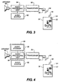
- FIG. 3 shows, in schematic form, a system for storing or retrieving recorded audio from a print 30 having transponder 22 coupled thereto.
- Transceiver 50 connects to an antenna 56.
- Transceiver 50 may be, for example, a "HOUSED READER AND ANTENNA" transceiver, part number RI-K01-320A-00, available from Texas Instruments, Incorporated, located in Dallas, Texas, USA.
- transceiver 50 is capable of transmitting a first electromagnetic frequency 64 of a first predetermined frequency, for reasons disclosed presently.
- Transceiver 50 is also capable of receiving a second electromagnetic frequency 66 of a second predetermined frequency, for reasons disclosed presently.
- transceiver 50 communicates with transponders 22 over a variable distance.
- the distance between antenna 56 and transponder 22 can range from very close proximity to as far as 18 inches.
- greater distances are possible, using correspondingly higher levels of RF output power.
- antenna 56 can have any orientation relative to the position of transponder 22, provided that communication frequencies 64 and 66 are not impeded by shielding.
- Transponder 22 is a low-power device that is tuned to a carrier frequency emitted by transceiver 50.
- This carrier frequency is in the Radio Frequency (RF) range.
- the carrier frequency could alternately be in another frequency range, for example, at a microwave frequency.
- transponder 22 circuitry Upon receiving an initial signal from transceiver 50, transponder 22 circuitry obtains, from the emitted electromagnetic energy, sufficient energy to provide source voltage for its internal circuitry. This is advantageous because no battery is needed to separately power transponder 22.
- Each transponder 22 can be individually programmed with a unique identifying address code (ID). Transponder 22 may be manually attached to print 30 at a final assembly or at any print processing stage. Other attachment methods are possible, as described herein below.
- ID unique identifying address code
- Transceiver 50 has both read and write access to memory data stored in memory 24 on transponder 22.
- transceiver 50 encodes a unique identifying address code as part of its emitted signal, along with a command to read data from or to write data to (i.e., program) memory 24 of transponder 22.
- Transponder 22 responds to transceiver 50 communication when it has been addressed using the correct encoded ID.
- first electromagnetic frequency 64 could employ, for example, Amplitude Modulation (AM), Frequency Modulation (FM), Frequency-Shift Keying (FSK), or other means for encoding the address of data transfer to or from memory 24 in transponder 22.
- AM Amplitude Modulation
- FM Frequency Modulation
- FSK Frequency-Shift Keying
- transceiver 50 encodes the following information during its transmission of first electromagnetic frequency 64:
- the data for storage listed as (c) immediately herein above can be a complete audio segment, digitally encoded and compressed, for example.
- the data for storage in memory 24 can itself be an address, or "pointer" to a memory location on a separate storage device, as described subsequently.
- second electromagnetic frequency 66 transmitted by transponder 22 in response to first electromagnetic frequency 64, is conditioned by the data stored in memory 24. That is, transponder 22 applies modulation to second electromagnetic frequency 66 that is sent in response to first electromagnetic frequency 64.
- Transceiver 50 extracts the data encoded in returned electromagnetic frequency 66.
- This data can either be a complete digitized audio signal, or can simply be a data pointer serving as an address to a location on a separate storage device where the corresponding audio for print 30 is separately stored.
- transceiver 50 is electrically coupled to an audio processing unit 84.
- Audio processing unit 84 may operate in either of two ways:
- Fig. 4 shows the additional components that would be used listed in case (2) immediately hereinabove where the data returned from memory 24 is a pointer to stored recorded audio.
- the recorded audio is stored in audio storage 88, as part of audio storage and playback unit 80.
- audio processing unit 84 provides the pointer information to audio storage 88.
- Audio storage 88 responds by providing the audio segment back to audio processing unit 84 for playback on speaker 86.
- transceiver 50 and antenna 56 components there are a number of possible embodiments for the transceiver 50 and antenna 56 components.
- these components can be hand-held.
- Antenna 56 could be fabricated in the form of a "wand" to be waved toward print 30 when it is desired to play back the corresponding audio.
- Audio source 82 provides the audio segment for storage in memory 24. Audio source 82 can include audio that was originally recorded on the film negative (for example, using the mechanism disclosed in U.S. Patent No. 4,905,029) or in memory circuitry when a photograph is taken (for example, using the mechanism disclosed in U.S. Patent No. 5,128,700) or could originate from another other audio input device.
- An audio segment can be digitally stored in any one of a number of possible data formats.
- audio data could be provided in WAV ( Wav eform Audio) format, familiar to users of well known operating systems for personal computers.
- WAV Wav eform Audio
- MIDI M usical I nstrument D igital I nterface
- MIDI files are very compact when contrasted with sound storage formats. Compression methods could also be employed to reduce the size of stored audio segments, thereby extending the length of the playback interval available.
- Transponder 22 may be provided on adhesive-backed material for attachment to print substrate 28.
- adhesive-backed material for attachment to print substrate 28.
- other modes of attachment are possible and are considered within the scope of the present invention.
- transponder 22 can be laminated onto print 30. Alternately, transponder 22 can be embedded within print 30 during manufacture of paper substrate 28.
- Antenna 26 is integrally connected to transponder 22. However, antenna 26 can be separately provided on a substrate material. This arrangement would then allow transponder 22 to be handled separately and affixed to print 30 after an audio segment is programmed.
- an algorithm uses a computational loop that proceeds in steps to increase transceiver 50 output power from an initially low value as transceiver 50 repeatedly polls for a transponder 22. As soon as transceiver 50 detects one of the transponders 22, transceiver 50 communicates with that transponder 22 and then temporarily disables that transponder 22. Transceiver 50 can then repeat polling in this fashion, incrementing its output power level slightly with each polling operation, to sequentially locate, communicate with, and then temporarily disable each next available transponder 22. In this way, transceiver 50 communicates with multiple transponders 22 in order of their return signal strength, until each transponder 22 on a page of album 20 has been contacted.
- audio processing unit 84 can be a component of a desktop computer, as might be appropriate when the audio message is initially stored in memory 24.
- Memory 24 can be provided in read/write form or can be write-protected, allowing read-only access to audio data stored on print 30.
- transponder 22 could be automatically attached to print 20 or could be provided for attachment by an operator of printing equipment as part of a post-printing or finishing process. Or, transponder 22 could be built into paper substrate 28 itself and could thereby be "invisible" to an operator or user of the print.
- antenna 26 could be imprinted onto a surface of the substrate.
- antenna 26 could be integrated into a substrate material, as part of the receiver manufacture or processing.
- a print having an attached data storage and allowing contactless access to stored data (e.g., audio data) associated with the print.
Abstract
Description
- This invention generally relates to prints processed by image processing apparatus and more particularly relates to a print having attached audio data storage and method of providing same.
- It can be appreciated that for a monochrome or color print, such as a photograph, the viewer's experience of and appreciation of the print is enhanced when recorded sound is associated with the print and can be played-back as the print is viewed. A recorded sound associated with a photograph in an album, for example, can be a recorded voice message, or a short segment of recorded music, or even background sound recorded when the photograph was taken.
- For example, U.S. Patent No.5,290,190 issued March 1, 1994 to McClanahan and U.S. Patent No. 4,990,092 issued February 5, 1991 to Cummings disclose a "talking book", wherein recorded sound associated with a page or picture can be played-back when a button is pushed.
- Similarly, U.S. Patent No. 5,574,519 issued November 12, 1996 to Manico, et al. discloses a bound "talking photo album" that allows recorded sound associated with an individual photograph to be played back when a photograph is placed in a viewer or scanned using an optical wand.
- In addition, U.S. Patent No. 4,905,029 issued February 27, 1990 to Kelley discloses a camera adapted to record sound onto a magnetic strip that is integrally attached to a photograph. A photograph produced by the device is inserted into a reader (which may be part of the camera body itself) for playing back the sound.
- Similarly, U.S. Patent No. 4,270,854 issued June 2, 1981 to Stemme et al. discloses a camera for recording sound data on a magnetic strip that is attached to an instant camera print.
- With respect to the Kelly and Stemme et al. devices, a magnetic strip, preferably attached to the photograph, is the primary means for recording audio associated with a photograph. However, disadvantages of this arrangement include the limited expected lifespan of magnetic recording media, difficulty of reproducing and reprinting photographs so configured, and possibility of erasure of the recorded audio by stray magnetic fields. Moreover, magnetic film is susceptible to damage in handling, and scratches or dirt on the magnetic material can render the medium unreadable. In addition, storage capability of a magnetic strip is severely limited, constraining the recorded message to within a few seconds duration at best. Further, magnetic media is typically passed through a reader device in order to swipe the media within a precise distance of a read head. This raises the need to provide precise manufacturing tolerances for the reader device, which in turn increases manufacturing costs.
- Another method for audio storage with a photographic print includes encoding the audio signal digitally and providing the encoded signal in optically readable form. In this regard, U.S. Patent No. 4,600,280 issued July 15, 1986 to Clark discloses use of optical encoding to store an audio signal on a transparent film, such as is used for motion pictures.
- Employing a similar concept for opaque photographic prints, U.S. Patent No. 5,521,663 issued May 28, 1996 to Norris discloses optical encoding for an opaque print, in which a camera is adapted to record sound onto the photographic film itself using optical encoding.
- Disadvantages of the Clark and Norris devices include the requirement to print encoded audio information as part of the imageable area of the film, reducing the overall usable area for the image. Further, in order to obtain the encoded data, the imaged area containing the encoding must be precisely scanned by an optical reader, thereby leading to relatively complex reader components. Yet another disadvantage is that optical encoding does not provide a useful method for subsequent erasure and re-recording of an audio segment.
- On the other hand, storage of audio data on an integrated circuit (IC) memory has advantages over magnetic storage and optical storage. Use of an integrated circuit memory that contains a digitally encoded audio signal and that is attached to a photographic print is disclosed in U.S. Patent No. 5,774,752 issued June 30, 1998 to Patton et al.
- In addition, U.S. Patent No. 4,905,029 issued February 27, 1990 to Kelley discloses use of an attached IC memory chip as an alternative audio storage method, where the chip stores the audio data for access from an external magnetic read head. The IC chip disclosed in U.S. Patent No. 4,905,029 receives its source power from the external read head by means of induction coils connected to the chip. The coils allow chip circuitry to obtain sufficient current (from the magnetic field exerted by the read head) to power memory and logic support circuitry internal to the chip. It is important to note that this arrangement presents a number of limitations. Among these are the following:
- (a) A magnetic read head must be passed within very close proximity to the IC memory chip (within a fraction of an inch of the chip), and with the proper orientation relative to the chip, in order to provide power to and to communicate with the chip. This is due to the nature of electromagnetic induction, since a "closed" magnetic circuit is required for transformer action. Thus, while this method provides "contactless" communication, it is required that a viewer pass a read head within close proximity to the chip.
- (b) A ferromagnetic shield would be needed to confine interaction between a read head device and one IC chip at a time. Otherwise, where a grouping contains multiple prints having corresponding IC chips, a read head could inadvertently activate more than one IC memory chip. In a photo album, for example, this would require the cumbersome solution of using a backing sheet of ferromagnetic material placed behind a print for which an audio signal is to be obtained.
-
- All of the aforementioned solutions for storing and retrieving audio data associated with a print present disadvantages when usability and cost are considered. Solutions using magnetic strips require either handling of the print, passing the print through a reader, or passing a read head in close proximity to the magnetic strip surface. Similarly, solutions using optical encoding require a print, in proper orientation, to be scanned using a wand or other reading device. Other solutions that would require connection to an IC on the print itself present additional problems. In this regard, connectors add cost and present potential reliability problems from dust and dirt and wear problems due to repeated connection/disconnection duty cycles.
- For contactless communication, RFID (Radio Frequency IDentification) tags having an integrally attached memory are commercially available. Currently, RF ID tags are used in applications when it is useful to store unique identifying information associated with an item in a manner such that the information is attached to the item. For example, RF ID tags have been proposed for use in applications with passports and credit cards, such as is disclosed in U.S. Patent No. 5,528,222 issued June 18, 1996 to Moskowitz et al.
- A commercially available RFID tag is the "TAG-IT™ INLAY", manufactured by Texas Instruments, Incorporated, located in Dallas, Texas, USA, can be used to provide information related to a device to which it is attached. This thin, flexible type of RF ID tag can be used, for example, in an application that previously employed a label or bar code. The applications noted in U.S. Patent No. 5,528,222 issued June 18, 1996 and the "TAG-IT™ INLAY" are primarily for identification purposes, such as for employee badges, for inventory control, or for credit card account identification. However, these devices are not used for storing audio or audio-related information.
- Thus, it is seen that while there are advantages to storing, as part of a photographic print, audio data associated with that print, there are no satisfactory solutions that allow storage of such audio data in a durable, reproducible, and rerecordable form. In addition, the prior art apparently does not disclose devices or methods that allow contactless read/write access which can be initiated from a variable position relative to a print and over a variable distance from a print, for the purpose of storage and retrieval of audio associated with an image on the print. It is an object of the present invention to provide a print having audio data attached thereto, wherein the audio data can be recorded onto the print or played back upon initiation by an observer.
- With the above object in view, the invention is defined by the several claims appended hereto.
- According to an aspect of the present invention, a print substrate has an attached non-volatile semiconductor memory component that is integrally connected to a transponder. The memory component may be, for example, an EEPROM (Electrically Erasable Programmable Read-Only Memory). Stored in the memory component are encoded data for a digitally encoded, recorded audio segment. A transceiver generates a first electromagnetic frequency that provides source power for the transponder. When it receives the first electromagnetic frequency, the transponder generates a second electromagnetic frequency in response to the first electromagnetic frequency. The second electromagnetic frequency is conditioned by the stored recorded audio segment stored in the memory.
- According to another aspect of the present invention, a print substrate has an attached non-volatile semiconductor memory component, integrally connected to a transponder, which stores a digital address that indicates where a recorded audio segment for a specific print is located. When it receives the first electromagnetic frequency, the transponder generates a second electromagnetic frequency in response to the first electromagnetic frequency. The second electromagnetic frequency is conditioned by the stored recorded address for an audio signal stored on a device.
- A feature of the present invention is the ability of a transceiver to act as a "writer" that stores, on a memory that is attached to the print substrate, recorded audio or information on the storage location of recorded audio.
- Another feature of the present invention is the ability of the transceiver to act also as a "reader" that retrieves stored audio information from the memory.
- An advantage of the present invention that it allows an audio signal that is uniquely associated with a print to be integrally attached to the print for automated play-back.
- Another advantage of the present invention that it provides a contactless communication interface, accessing recorded audio or related data without requiring that electrical contact be made to corresponding contacts mounted on a print.
- A further advantage of the present invention that it allows a print having attached recorded audio to be easily reproduced, because audio data is stored in digitized form.
- These and other objects, features, and advantages of the present invention will become apparent to those skilled in the art upon a reading of the following detailed description when taken in conjunction with the drawings wherein there are shown and described illustrative embodiments of the invention.
- While the specification concludes with claims particularly pointing out and distinctly claiming the subject matter of the present invention, it is believed the invention will be better understood from the following description when taken in conjunction with the accompanying drawings, wherein:
- Figure 1 is a plan view of a print having a transponder coupled to the print;
- Figure 2 is a perspective view showing prints arranged in an album, each print having an attached memory that stores a pointer to recorded audio data that is stored on a separate component within the album;
- Figure 3 is a schematic view showing components used to store or retrieve recorded audio on a print; and
- Figure 4 is a schematic view showing components used in an alternative embodiment of the present invention, in which the audio segment is stored separately from the print.
-
- The present description is directed in particular to elements forming part of, or cooperating more directly with, apparatus in accordance with the invention. It is to be understood that elements not specifically shown or described may take various forms well known to those skilled in the art.
- For the description that follows, the general term "print" is used to indicate an output image from an image processing apparatus, reproduced onto a substrate, where the image is reproduced using a colorant such as ink or dyes, or using exposure methods well known in the art. By way of example only, and not by way of limitation, a print, as the term is used herein and as generally numbered 30 in the following description, could be any of the following:
- a photographic print;
- a printed output sheet, such as from a proofing system, including digital proofing systems that use thermal print technologies, from inkjet printers, or from photofinishing printers that use photosensitive film or paper that is exposed to a light source and developed using a subsequent chemical process for creating an image;
- a developed X-ray, ultrasound, or other diagnostic image; or
- an aerial photograph.
-
- A substrate, generally numbered 42 in the following description, may be any suitable material and is typically found in sheet form and can include, for example, generally opaque materials such as paper, cardboard, textile, and vinyl, or generally transparent materials such as film, or other materials capable of accepting a printed image.
- The recorded audio, also termed "audio segment" herein, can originate from any of a number of possible sources. For example, the audio can be recorded at the time a photograph is taken. This would be possible, for example, using a camera as disclosed in U.S. Patent No. 5,128,700 issued July 7, 1992 to Inoue et al. Or, a separately recorded audio segment can be provided, recorded into memory by a technician when a print is developed. As yet another example, recorded audio can be programmed by a customer after receiving the developed print.
- Fig. 1 shows a
transponder 22 attached to aprint 30, imaged onto apaper substrate 28.Transponder 22 may be a "TAG-IT™ INLAY" which incorporates amemory 24, anantenna 26, and internal RF communication and power supply circuitry (not shown).Transponder 22 can be attached to the front or back ofprint 30 using an adhesive-tape backing, laminated ontoprint 30, embodied withinpaper substrate 28 or attached using an alternate arrangement such as described herein below. - Referring again to Fig. 1,
transponder 22 is shown attached along an edge ofpaper substrate 28, away from the image area ofprint 30. This is only one possible arrangement, becausetransponder 22 can be attached in any suitable position onprint 30, including on the back side ofprint 30. - Figure 2 shows
print 30 having attachedtransponder 22 disposed in analbum 20. With this arrangement, a separate audio storage and playback unit 80 (shown in dotted outline in Fig. 2) may be part ofalbum 20. In this configuration of the invention, it is possible to store the recorded audio for aprint 30 on a magnetic tape or other storage device that is attached toalbum 20. This arrangement would allowtransponder 22 onprint 30 to store only minimal data indicating an address or pointer to recorded audio that is stored on audio storage andplayback unit 80. - It is instructive to describe how audio data can be recorded into
memory 24 onprint 30 or retrieved frommemory 24. Fig. 3 shows, in schematic form, a system for storing or retrieving recorded audio from aprint 30 havingtransponder 22 coupled thereto. - Referring to Fig. 3, a
transceiver 50 connects to anantenna 56.Transceiver 50 may be, for example, a "HOUSED READER AND ANTENNA" transceiver, part number RI-K01-320A-00, available from Texas Instruments, Incorporated, located in Dallas, Texas, USA. In operation,transceiver 50 is capable of transmitting a firstelectromagnetic frequency 64 of a first predetermined frequency, for reasons disclosed presently.Transceiver 50 is also capable of receiving a secondelectromagnetic frequency 66 of a second predetermined frequency, for reasons disclosed presently. - Notably, communication at a predetermined frequency, by means of
antenna 56, betweentransceiver 50 andtransponders 22 can take place over a variable distance. For typical low-power RF devices such as the aforementioned "TAG-IT INLAY"™, the distance betweenantenna 56 andtransponder 22 can range from very close proximity to as far as 18 inches. However, greater distances are possible, using correspondingly higher levels of RF output power. Moreover,antenna 56 can have any orientation relative to the position oftransponder 22, provided thatcommunication frequencies -
Transponder 22 is a low-power device that is tuned to a carrier frequency emitted bytransceiver 50. This carrier frequency is in the Radio Frequency (RF) range. However, the carrier frequency could alternately be in another frequency range, for example, at a microwave frequency. Upon receiving an initial signal fromtransceiver 50,transponder 22 circuitry obtains, from the emitted electromagnetic energy, sufficient energy to provide source voltage for its internal circuitry. This is advantageous because no battery is needed to separatelypower transponder 22. - Each
transponder 22 can be individually programmed with a unique identifying address code (ID).Transponder 22 may be manually attached to print 30 at a final assembly or at any print processing stage. Other attachment methods are possible, as described herein below. -
Transceiver 50 has both read and write access to memory data stored inmemory 24 ontransponder 22. To communicate withtransponder 22,transceiver 50 encodes a unique identifying address code as part of its emitted signal, along with a command to read data from or to write data to (i.e., program)memory 24 oftransponder 22.Transponder 22 responds to transceiver 50 communication when it has been addressed using the correct encoded ID. - Data is transferred between
transceiver 50 andtransponder 22 by modulation of the respective electromagnetic frequency. By way of illustration, modulation of firstelectromagnetic frequency 64 could employ, for example, Amplitude Modulation (AM), Frequency Modulation (FM), Frequency-Shift Keying (FSK), or other means for encoding the address of data transfer to or frommemory 24 intransponder 22. Toprogram memory 24,transceiver 50 encodes the following information during its transmission of first electromagnetic frequency 64: - (a) a command to write data to
memory 24; - (b) an address of the data to be written in
memory 24; and, - (c) the data for storage at the address specified at address (b) above
in
memory 24. -
- It is important to note that the data for storage listed as (c) immediately herein above can be a complete audio segment, digitally encoded and compressed, for example. Alternately, the data for storage in
memory 24 can itself be an address, or "pointer" to a memory location on a separate storage device, as described subsequently. - Referring again to Fig. 3, second
electromagnetic frequency 66, transmitted bytransponder 22 in response to firstelectromagnetic frequency 64, is conditioned by the data stored inmemory 24. That is,transponder 22 applies modulation to secondelectromagnetic frequency 66 that is sent in response to firstelectromagnetic frequency 64.Transceiver 50 extracts the data encoded in returnedelectromagnetic frequency 66. This data can either be a complete digitized audio signal, or can simply be a data pointer serving as an address to a location on a separate storage device where the corresponding audio forprint 30 is separately stored. - Referring again to Fig. 3,
transceiver 50 is electrically coupled to anaudio processing unit 84.Audio processing unit 84 may operate in either of two ways: - (1) If a complete audio segment is stored in
memory 24 ontransponder 22, process (amplify) the audio segment for the viewer and direct this signal tospeaker 86. - (2) If the data stored in
memory 24 ontransponder 22 is a pointer to a stored recorded audio segment, access the stored audio for replay to the viewer. -
- Fig. 4 shows the additional components that would be used listed in case (2) immediately hereinabove where the data returned from
memory 24 is a pointer to stored recorded audio. Here, the recorded audio is stored inaudio storage 88, as part of audio storage andplayback unit 80. When it receives the pointer information frommemory 24,audio processing unit 84 provides the pointer information toaudio storage 88.Audio storage 88 responds by providing the audio segment back toaudio processing unit 84 for playback onspeaker 86. - Referring to Figs. 3 and 4, there are a number of possible embodiments for the
transceiver 50 andantenna 56 components. For example, these components can be hand-held.Antenna 56 could be fabricated in the form of a "wand" to be waved towardprint 30 when it is desired to play back the corresponding audio.Audio source 82 provides the audio segment for storage inmemory 24.Audio source 82 can include audio that was originally recorded on the film negative (for example, using the mechanism disclosed in U.S. Patent No. 4,905,029) or in memory circuitry when a photograph is taken (for example, using the mechanism disclosed in U.S. Patent No. 5,128,700) or could originate from another other audio input device. - An audio segment, either stored directly in
memory 24 or separately inaudio storage 88, can be digitally stored in any one of a number of possible data formats. By way of example only, and not by way of limitation, audio data could be provided in WAV (Waveform Audio) format, familiar to users of well known operating systems for personal computers. Where it is desirable to store a sequence of discrete-frequency musical tones for playback (rather than more complex audio having voice components or recorded sound) a MIDI (Musical Instrument Digital Interface) file format can be utilized. MIDI files are very compact when contrasted with sound storage formats. Compression methods could also be employed to reduce the size of stored audio segments, thereby extending the length of the playback interval available. -
Transponder 22, as is the case with a "TAG-IT INLAY"™, may be provided on adhesive-backed material for attachment to printsubstrate 28. Of course, other modes of attachment are possible and are considered within the scope of the present invention. - As one method of attachment,
transponder 22 can be laminated ontoprint 30. Alternately,transponder 22 can be embedded withinprint 30 during manufacture ofpaper substrate 28. -
Antenna 26 is integrally connected totransponder 22. However,antenna 26 can be separately provided on a substrate material. This arrangement would then allowtransponder 22 to be handled separately and affixed to print 30 after an audio segment is programmed. - Where
multiple prints 30 are stored inalbum 20, it may be necessary to provide isolation in some form so as to restrict communication to only asingle transponder 22 at a time. That is, it is necessary to prevent a "collision" condition in which two ormore transponders 22 simultaneously respond to firstelectromagnetic frequency 64 as was described using Figs. 3 and 4. Where RF frequencies are used for communication, shielding could take the form of thin aluminum sheets placed between prints, for example. However, other methods are available using programming techniques that allow communication with asingle transponder 22 at a time. As one example, an alternative polling technique employs a "non-collision" algorithm developed for communicating with multiple transponders grouped in a confined area. In one embodiment of such a technique, an algorithm uses a computational loop that proceeds in steps to increasetransceiver 50 output power from an initially low value astransceiver 50 repeatedly polls for atransponder 22. As soon astransceiver 50 detects one of thetransponders 22,transceiver 50 communicates with thattransponder 22 and then temporarily disables thattransponder 22.Transceiver 50 can then repeat polling in this fashion, incrementing its output power level slightly with each polling operation, to sequentially locate, communicate with, and then temporarily disable each nextavailable transponder 22. In this way,transceiver 50 communicates withmultiple transponders 22 in order of their return signal strength, until eachtransponder 22 on a page ofalbum 20 has been contacted. - While the invention has been described with particular reference to its preferred embodiments, it will be understood by those skilled in the art that various changes may be made and equivalents may be substituted for elements in the preferred embodiments without departing from the scope of the invention. For example,
audio processing unit 84 can be a component of a desktop computer, as might be appropriate when the audio message is initially stored inmemory 24.Memory 24 can be provided in read/write form or can be write-protected, allowing read-only access to audio data stored onprint 30. In addition,transponder 22 could be automatically attached to print 20 or could be provided for attachment by an operator of printing equipment as part of a post-printing or finishing process. Or,transponder 22 could be built intopaper substrate 28 itself and could thereby be "invisible" to an operator or user of the print. - There are also a number of possible alternate arrangements for integrating
antenna 26 onto or within a print substrate. For example,antenna 26 could be imprinted onto a surface of the substrate. Or,antenna 26 could be integrated into a substrate material, as part of the receiver manufacture or processing. - Therefore, what is provided is a print having an attached data storage and allowing contactless access to stored data (e.g., audio data) associated with the print.
Claims (30)
- A storage apparatus for storing audio data on an output print (30) produced by an image processing apparatus, comprising:(a) a memory (24) coupled to the output print, said memory adapted to store audio data associated with the image;(b) a transponder (22) integrally coupled with said memory, said transponder capable of receiving a first electromagnetic frequency and, in response to the first electromagnetic frequency received thereby, generating a second electromagnetic frequency, the second electromagnetic frequency being characteristic of the data stored in said memory;(c) a transceiver (50) spaced-apart from the output print for transmitting said first electromagnetic frequency and for sensing the second electromagnetic frequency; and(d) a data processing unit (32, 84) coupled to said transceiver, said data processing unit adapted to communicate with said transceiver for facilitating exchange of the data between said transceiver and said memory.
- The storage apparatus of claim 1, wherein said transceiver transmits the first electromagnetic frequency at a predetermined first frequency.
- The storage apparatus of claim 1 wherein said transceiver receives the second electromagnetic frequency at a predetermined second frequency.
- The storage apparatus of claim 1, wherein said memory is adapted to store machine-readable audio data associated with the image.
- The storage apparatus of claim 4, wherein said data processing unit is an audio data processing unit (84).
- The storage apparatus of claim 1, wherein said data processing unit is a computer (32).
- The storage apparatus of claim 1, further comprising an audio storage unit (88) spaced apart from the output print, said audio storage unit adapted to store audio data associated with the image.
- A print, comprising:(a) a substrate (28);(b) a memory coupled to said substrate, said memory adapted to store data therein;(c) a transponder coupled to said memory, said transponder capable of receiving a first electromagnetic frequency and, in response to the first electromagnetic frequency received thereby, generating a second electromagnetic frequency, the second electromagnetic frequency being characteristic of the data stored in said memory.
- The print of claim 8, further comprising an antenna (56) coupled to said transponder.
- The print of claim 8, wherein said memory has audio data stored therein.
- The print of claim 8, wherein said memory has audio data stored therein, the audio data being in the form of a digitally encoded audio file.
- The print of claim 8, wherein said memory has audio data stored therein, the audio data being in the form of a pointer that identifies the digitally encoded audio file.
- The print of claim 8, wherein said memory is a read/write memory.
- The print of claim 8, wherein said substrate is paper.
- The print of claim 8, wherein said substrate is film.
- A method of assembling a storage apparatus for storing audio data on an output print produced by an image processing apparatus, comprising the steps of:(a) coupling a memory to the output print, the memory adapted to store data associated with the image;(b) integrally coupling a transponder with the memory, the transponder capable of receiving a first electromagnetic frequency and, in response to the first electromagnetic frequency received thereby, generating a second electromagnetic frequency, the second electromagnetic frequency being characteristic of the data stored in the memory;(c) providing a transceiver adapted to be spaced-apart from the output print for transmitting the first electromagnetic frequency and for sensing the second electromagnetic frequency; and(d) coupling a data processing unit to the transceiver, the data processing unit adapted to communicate with the transceiver for facilitating exchange of the data between the transceiver and the memory.
- The method of claim 16, wherein the step of providing a transceiver comprises the step of providing a transceiver adapted to transmit the first electromagnetic frequency at a predetermined first frequency.
- The method of claim 16, wherein the step of providing a transceiver comprises the step of providing a transceiver adapted to receive the second electromagnetic frequency at a predetermined second frequency.
- The method of claim 16, wherein the step of coupling a memory comprises the step of coupling a memory adapted to store machine-readable audio data associated with the image.
- The method of claim 19, wherein the step of coupling a data processing unit comprises the step of coupling an audio data processing unit.
- The method of claim 16, wherein the step of coupling an audio data processing unit comprises the step of coupling a computer.
- The method of claim 16, further comprising the step of disposing an audio storage unit spaced apart from the output print, the audio storage unit adapted to store audio data associated with the image.
- A method of providing a print, comprising the steps of:(a) providing a substrate;(b) coupling a memory to the substrate, the memory adapted to store data therein;(c) coupling a transponder to the memory, the transponder capable of receiving a first electromagnetic frequency and, in response to the first electromagnetic frequency received thereby, generating a second electromagnetic frequency, the second electromagnetic frequency being characteristic of the data stored in the memory.
- The method of claim 23, further comprising the step of coupling an antenna to the transponder.
- The method of claim 23, wherein the step of coupling a memory comprises the step coupling a memory having audio data stored therein.
- The method of claim 23, wherein the step of coupling a memory comprises the step of coupling a memory having audio data stored therein in the form of a digitally encoded audio file.
- The method of claim 26, wherein the step of coupling a comprises the step of coupling a memory having audio data stored therein in the form of a pointer that identifies the digitally encoded audio file.
- The method of claim 23, wherein the step of coupling a memory comprises the step of coupling a memory that is a read/write memory.
- The method of claim 23, wherein the step of providing a substrate comprises the step of providing a paper substrate.
- The method of claim 23, wherein the step of providing a substrate comprises the step of providing a film substrate.
Applications Claiming Priority (2)
| Application Number | Priority Date | Filing Date | Title |
|---|---|---|---|
| US372442 | 1989-06-27 | ||
| US09/372,442 US6363239B1 (en) | 1999-08-11 | 1999-08-11 | Print having attached audio data storage and method of providing same |
Publications (2)
| Publication Number | Publication Date |
|---|---|
| EP1079268A1 true EP1079268A1 (en) | 2001-02-28 |
| EP1079268B1 EP1079268B1 (en) | 2002-10-02 |
Family
ID=23468136
Family Applications (1)
| Application Number | Title | Priority Date | Filing Date |
|---|---|---|---|
| EP00202718A Revoked EP1079268B1 (en) | 1999-08-11 | 2000-07-31 | A print having attached audio data storage and method of providing same |
Country Status (4)
| Country | Link |
|---|---|
| US (1) | US6363239B1 (en) |
| EP (1) | EP1079268B1 (en) |
| JP (1) | JP2001119320A (en) |
| DE (1) | DE60000530T2 (en) |
Cited By (1)
| Publication number | Priority date | Publication date | Assignee | Title |
|---|---|---|---|---|
| GB2386464A (en) * | 2002-03-13 | 2003-09-17 | Hewlett Packard Co | Photo album with provision for media playback via surface area network |
Families Citing this family (34)
| Publication number | Priority date | Publication date | Assignee | Title |
|---|---|---|---|---|
| US6786420B1 (en) | 1997-07-15 | 2004-09-07 | Silverbrook Research Pty. Ltd. | Data distribution mechanism in the form of ink dots on cards |
| US6618117B2 (en) | 1997-07-12 | 2003-09-09 | Silverbrook Research Pty Ltd | Image sensing apparatus including a microcontroller |
| US6985207B2 (en) * | 1997-07-15 | 2006-01-10 | Silverbrook Research Pty Ltd | Photographic prints having magnetically recordable media |
| US6690419B1 (en) | 1997-07-15 | 2004-02-10 | Silverbrook Research Pty Ltd | Utilising eye detection methods for image processing in a digital image camera |
| US6879341B1 (en) | 1997-07-15 | 2005-04-12 | Silverbrook Research Pty Ltd | Digital camera system containing a VLIW vector processor |
| US6624848B1 (en) | 1997-07-15 | 2003-09-23 | Silverbrook Research Pty Ltd | Cascading image modification using multiple digital cameras incorporating image processing |
| US7551201B2 (en) | 1997-07-15 | 2009-06-23 | Silverbrook Research Pty Ltd | Image capture and processing device for a print on demand digital camera system |
| US7110024B1 (en) | 1997-07-15 | 2006-09-19 | Silverbrook Research Pty Ltd | Digital camera system having motion deblurring means |
| AUPP702098A0 (en) | 1998-11-09 | 1998-12-03 | Silverbrook Research Pty Ltd | Image creation method and apparatus (ART73) |
| AUPQ056099A0 (en) | 1999-05-25 | 1999-06-17 | Silverbrook Research Pty Ltd | A method and apparatus (pprint01) |
| US6750978B1 (en) * | 2000-04-27 | 2004-06-15 | Leapfrog Enterprises, Inc. | Print media information system with a portable print media receiving unit assembly |
| US6668156B2 (en) | 2000-04-27 | 2003-12-23 | Leapfrog Enterprises, Inc. | Print media receiving unit including platform and print media |
| US7916124B1 (en) | 2001-06-20 | 2011-03-29 | Leapfrog Enterprises, Inc. | Interactive apparatus using print media |
| US7239842B2 (en) * | 2002-05-22 | 2007-07-03 | Thomson Licensing | Talking E-book |
| US20040015988A1 (en) * | 2002-07-22 | 2004-01-22 | Buvana Venkataraman | Visual medium storage apparatus and method for using the same |
| US20040104890A1 (en) * | 2002-09-05 | 2004-06-03 | Leapfrog Enterprises, Inc. | Compact book and apparatus using print media |
| US20040049733A1 (en) * | 2002-09-09 | 2004-03-11 | Eastman Kodak Company | Virtual annotation of a recording on an archival media |
| US20040135902A1 (en) * | 2003-01-09 | 2004-07-15 | Eventshots.Com Incorporated | Image association process |
| GB2404271B (en) * | 2003-07-24 | 2006-06-21 | Hewlett Packard Development Co | Print having attached data storage, storage medium therefore and method of providing same |
| TWI266996B (en) * | 2004-02-06 | 2006-11-21 | Hi Touch Imaging Tech Co Ltd | Image and audio data processing system |
| US20050191604A1 (en) * | 2004-02-27 | 2005-09-01 | Allen William H. | Apparatus and method for teaching dyslexic individuals |
| US20060078866A1 (en) * | 2004-03-17 | 2006-04-13 | James Marggraff | System and method for identifying termination of data entry |
| US7831933B2 (en) * | 2004-03-17 | 2010-11-09 | Leapfrog Enterprises, Inc. | Method and system for implementing a user interface for a device employing written graphical elements |
| US7453447B2 (en) * | 2004-03-17 | 2008-11-18 | Leapfrog Enterprises, Inc. | Interactive apparatus with recording and playback capability usable with encoded writing medium |
| US20060077184A1 (en) * | 2004-03-17 | 2006-04-13 | James Marggraff | Methods and devices for retrieving and using information stored as a pattern on a surface |
| US9105196B2 (en) | 2004-07-20 | 2015-08-11 | Proxtalker.Com, Llc | Method and system for autonomous teaching of braille |
| US9111463B2 (en) * | 2004-07-20 | 2015-08-18 | Proxtalker.Com, Llc | Interactive speech synthesizer for enabling people who cannot talk but who are familiar with use of anonym moveable picture communication to autonomously communicate using verbal language |
| US20060020470A1 (en) * | 2004-07-20 | 2006-01-26 | Glen Dobbs | Interactive speech synthesizer for enabling people who cannot talk but who are familiar with use of picture exchange communication to autonomously communicate using verbal language |
| GB2419456B (en) * | 2004-10-23 | 2010-01-27 | Hewlett Packard Development Co | Media content preview |
| US7922099B1 (en) | 2005-07-29 | 2011-04-12 | Leapfrog Enterprises, Inc. | System and method for associating content with an image bearing surface |
| US7485794B2 (en) * | 2006-03-24 | 2009-02-03 | Yamaha Corporation | Electronic musical instrument system |
| US8261967B1 (en) | 2006-07-19 | 2012-09-11 | Leapfrog Enterprises, Inc. | Techniques for interactively coupling electronic content with printed media |
| CN201177878Y (en) * | 2007-02-01 | 2009-01-07 | 邝天立 | Voice book |
| US20100076794A1 (en) * | 2008-09-16 | 2010-03-25 | William Seippel | Systems For Valuating and Tracking Items of Property |
Citations (5)
| Publication number | Priority date | Publication date | Assignee | Title |
|---|---|---|---|---|
| US4905029A (en) * | 1988-09-28 | 1990-02-27 | Kelley Scott A | Audio still camera system |
| US5521663A (en) * | 1992-10-28 | 1996-05-28 | Norris, Iii; Wyamn J. | Sound system for still film photography |
| US5528222A (en) * | 1994-09-09 | 1996-06-18 | International Business Machines Corporation | Radio frequency circuit and memory in thin flexible package |
| WO1998040930A1 (en) * | 1997-03-10 | 1998-09-17 | Precision Dynamics Corporation | Reactively coupled elements in circuits on flexible substrates |
| US5878292A (en) * | 1996-08-29 | 1999-03-02 | Eastman Kodak Company | Image-audio print, method of making and player for using |
Family Cites Families (47)
| Publication number | Priority date | Publication date | Assignee | Title |
|---|---|---|---|---|
| US3835301A (en) | 1973-02-21 | 1974-09-10 | Helert P | Card coding and read-out system |
| US3926633A (en) | 1973-07-02 | 1975-12-16 | Peter Anderson Custer | Motion picture film soundtrack and method for production thereof |
| US4208210A (en) | 1974-12-19 | 1980-06-17 | Fuji Photo Film Co., Ltd. | Process for forming an optical soundtrack |
| US4178183A (en) | 1978-07-27 | 1979-12-11 | Eastman Kodak Company | Thiazolyl coupler compositions and photographic elements suited to forming integral sound tracks |
| DE2840051A1 (en) | 1978-09-14 | 1980-03-27 | Agfa Gevaert Ag | PHOTOGRAPHIC IMMEDIATE IMAGE CAMERA |
| US4270853A (en) | 1979-03-21 | 1981-06-02 | West Electric Company, Ltd. | Sound-recording instant-printing film and camera therefor |
| US4600280A (en) | 1984-07-16 | 1986-07-15 | Clark Lloyd D | Digital audio recording/playback system for motion picture film |
| EP0176628B1 (en) | 1984-09-28 | 1987-11-25 | Agfa-Gevaert N.V. | Photographic colour elements |
| US4806958A (en) | 1988-01-11 | 1989-02-21 | Eastman Kodak Company | Cassette/machine optically coupled interface |
| US4855769A (en) | 1988-08-29 | 1989-08-08 | Polaroid Corporation | Photographic apparatus for motorized processing of instant film |
| JPH0236825U (en) | 1988-09-02 | 1990-03-09 | ||
| US5128700A (en) | 1989-05-12 | 1992-07-07 | Minolta Camera Kabushiki Kaisha | Camera capable of recording sounds relevant to the photographing |
| US4990092B1 (en) | 1989-08-14 | 1998-08-04 | Tonka Corp | Talking book |
| US5059126A (en) | 1990-05-09 | 1991-10-22 | Kimball Dan V | Sound association and learning system |
| US5184152A (en) | 1990-12-04 | 1993-02-02 | Sumimoto Electric Interconnect Products, Inc. | Printing apparatus and method for printing on an elongated member such as a tube |
| US5185315A (en) | 1991-02-21 | 1993-02-09 | Eastman Kodak Company | Making encoded dye-donor films for thermal printers |
| US5297881A (en) | 1991-05-16 | 1994-03-29 | Mitsubishi Steel Mfg. Co., Ltd. | Printing machine carriage having a magnetic encoder |
| US5268708A (en) | 1991-08-23 | 1993-12-07 | Eastman Kodak Company | Laser thermal printer with an automatic material supply |
| JP3155794B2 (en) | 1991-12-13 | 2001-04-16 | キヤノン株式会社 | Ink jet recording method and ink jet recording apparatus |
| US5331338A (en) | 1992-01-30 | 1994-07-19 | Printware, Inc. | Web steering for an image recorder |
| US5455617A (en) | 1992-03-27 | 1995-10-03 | Eastman Kodak Company | Thermal printer supply having non-volatile memory |
| US5342671A (en) | 1992-06-05 | 1994-08-30 | Eastman Kodak Company | Encoded dye receiver |
| US5310999A (en) * | 1992-07-02 | 1994-05-10 | At&T Bell Laboratories | Secure toll collection system for moving vehicles |
| US5290190A (en) | 1992-09-30 | 1994-03-01 | Mcclanahan Susan D | Talking book |
| US5513920A (en) | 1992-10-29 | 1996-05-07 | Eastman Kodak Company | Dye donor web loading apparatus for a thermal printer |
| US5606347A (en) * | 1992-12-16 | 1997-02-25 | Texas Instruments Incorporated | Devices systems and methods for flexible format data storage |
| US5305020A (en) | 1992-12-21 | 1994-04-19 | Tektronix, Inc. | Thermal transfer printer having media pre-coat selection apparatus and methods |
| US5537135A (en) | 1993-01-22 | 1996-07-16 | Gerber Scientific Products, Inc. | Method and apparatus for making a graphic product |
| JP3170528B2 (en) | 1993-01-28 | 2001-05-28 | 富士写真フイルム株式会社 | Thermal recording apparatus and method having shading correction function |
| EP0622239B1 (en) | 1993-04-30 | 1998-08-26 | Hewlett-Packard Company | Multiple ink jet print cartridge alignment system |
| US5516590A (en) | 1993-07-15 | 1996-05-14 | Ncr Corporation | Fluorescent security thermal transfer printing ribbons |
| JP3244371B2 (en) | 1993-12-22 | 2002-01-07 | オリンパス光学工業株式会社 | Audio information processing system and audio information processing method |
| JPH07186476A (en) | 1993-12-28 | 1995-07-25 | Sony Corp | Ribbon cartridge |
| US5565906A (en) | 1994-01-13 | 1996-10-15 | Schoonscan, Inc. | Clocking means for bandwise imaging device |
| US5598201A (en) | 1994-01-31 | 1997-01-28 | Hewlett-Packard Company | Dual-resolution encoding system for high cyclic accuracy of print-medium advance in an inkjet printer |
| NL9400392A (en) | 1994-03-11 | 1995-10-02 | Sallmetall Bv | Sheeting roll with information carrier |
| US5528377A (en) | 1994-03-29 | 1996-06-18 | E. I. Du Pont De Nemours And Company | Extended density color printing |
| US5574519A (en) | 1994-05-03 | 1996-11-12 | Eastman Kodak Company | Talking photoalbum |
| DE69516201T2 (en) | 1994-05-06 | 2000-08-24 | Kansai Paint Co Ltd | Process for making invisible marking and process for detecting invisible marking |
| US5600352A (en) | 1994-06-27 | 1997-02-04 | Tektronix, Inc. | Apparatus and method for controlling coalescence of ink drops on a print medium |
| US5491327A (en) | 1994-08-10 | 1996-02-13 | American Magnetics Corporation | Universal magnetic medium encoder with tilt-compensating apparatus |
| US5493385A (en) | 1994-12-09 | 1996-02-20 | Eastman Kodak Company | Electrophotographic color printer apparatus and method with improved registration of colors |
| US5713288A (en) | 1995-08-03 | 1998-02-03 | Frazzitta; Joseph R. | Method and apparatus for use in offset printing |
| US5647679A (en) | 1996-04-01 | 1997-07-15 | Itw Limited | Printer for printing on a continuous print medium |
| US5842118A (en) * | 1996-12-18 | 1998-11-24 | Micron Communications, Inc. | Communication system including diversity antenna queuing |
| US5774752A (en) | 1996-12-26 | 1998-06-30 | Eastman Kodak Company | Processing of sound media with still image films in photofinishing labs |
| US5914671A (en) * | 1997-02-27 | 1999-06-22 | Micron Communications, Inc. | System and method for locating individuals and equipment, airline reservation system, communication system |
-
1999
- 1999-08-11 US US09/372,442 patent/US6363239B1/en not_active Expired - Fee Related
-
2000
- 2000-07-31 DE DE60000530T patent/DE60000530T2/en not_active Revoked
- 2000-07-31 EP EP00202718A patent/EP1079268B1/en not_active Revoked
- 2000-08-11 JP JP2000244640A patent/JP2001119320A/en active Pending
Patent Citations (5)
| Publication number | Priority date | Publication date | Assignee | Title |
|---|---|---|---|---|
| US4905029A (en) * | 1988-09-28 | 1990-02-27 | Kelley Scott A | Audio still camera system |
| US5521663A (en) * | 1992-10-28 | 1996-05-28 | Norris, Iii; Wyamn J. | Sound system for still film photography |
| US5528222A (en) * | 1994-09-09 | 1996-06-18 | International Business Machines Corporation | Radio frequency circuit and memory in thin flexible package |
| US5878292A (en) * | 1996-08-29 | 1999-03-02 | Eastman Kodak Company | Image-audio print, method of making and player for using |
| WO1998040930A1 (en) * | 1997-03-10 | 1998-09-17 | Precision Dynamics Corporation | Reactively coupled elements in circuits on flexible substrates |
Cited By (3)
| Publication number | Priority date | Publication date | Assignee | Title |
|---|---|---|---|---|
| GB2386464A (en) * | 2002-03-13 | 2003-09-17 | Hewlett Packard Co | Photo album with provision for media playback via surface area network |
| GB2386464B (en) * | 2002-03-13 | 2005-08-24 | Hewlett Packard Co | Photo album with provision for media playback |
| US6975832B2 (en) | 2002-03-13 | 2005-12-13 | Hewlett-Packard Development Company, L.P. | Photo album with provision for media playback |
Also Published As
| Publication number | Publication date |
|---|---|
| JP2001119320A (en) | 2001-04-27 |
| DE60000530T2 (en) | 2003-06-18 |
| EP1079268B1 (en) | 2002-10-02 |
| DE60000530D1 (en) | 2002-11-07 |
| US6363239B1 (en) | 2002-03-26 |
Similar Documents
| Publication | Publication Date | Title |
|---|---|---|
| EP1079268B1 (en) | A print having attached audio data storage and method of providing same | |
| US6381418B1 (en) | Print having information associated with the print stored in a memory coupled to the print | |
| US6785739B1 (en) | Data storage and retrieval playback apparatus for a still image receiver | |
| EP1076259B1 (en) | Camera having radio-frequency identification transponder | |
| US6265977B1 (en) | Radio frequency identification tag apparatus and related method | |
| US6563563B2 (en) | Printing of image with related sound | |
| CA2564801A1 (en) | Rewritable card printer with retractable head | |
| US7391967B2 (en) | Camera system | |
| JP3529087B2 (en) | Read / write device for non-contact type IC card | |
| JP2003346086A (en) | Print viewing method and apparatus | |
| JP2007094837A (en) | Print device, print system, recording device, and printing paper | |
| EP1398731B1 (en) | Virtual annotation of a recording on an archival media | |
| JP2006053686A (en) | Electronic information system | |
| JPH11250205A (en) | Ic card | |
| JP3749728B2 (en) | Document management system | |
| JP3550866B2 (en) | Recording medium storage cassette | |
| JP2005117571A (en) | Image forming method and image forming apparatus | |
| JP2001229337A (en) | Electrical data reader/writer provided with bar code reading function | |
| US7009494B2 (en) | Media holder having communication capabilities | |
| GB2203699A (en) | Portable detachable data record | |
| JP3012580U (en) | Print record card | |
| JP2004118661A (en) | Ic memory cartridge and image data processing system | |
| KR200251265Y1 (en) | Contact/contactless compact disk card | |
| JP2000148946A (en) | Information reproduction system, information recording medium and information recording system | |
| JP2005047273A (en) | System and method of associating printing information with print media |
Legal Events
| Date | Code | Title | Description |
|---|---|---|---|
| PUAI | Public reference made under article 153(3) epc to a published international application that has entered the european phase |
Free format text: ORIGINAL CODE: 0009012 |
|
| AK | Designated contracting states |
Kind code of ref document: A1 Designated state(s): DE FR GB |
|
| AX | Request for extension of the european patent |
Free format text: AL;LT;LV;MK;RO;SI |
|
| 17P | Request for examination filed |
Effective date: 20010807 |
|
| GRAG | Despatch of communication of intention to grant |
Free format text: ORIGINAL CODE: EPIDOS AGRA |
|
| AKX | Designation fees paid |
Free format text: DE FR GB |
|
| 17Q | First examination report despatched |
Effective date: 20011024 |
|
| GRAG | Despatch of communication of intention to grant |
Free format text: ORIGINAL CODE: EPIDOS AGRA |
|
| GRAH | Despatch of communication of intention to grant a patent |
Free format text: ORIGINAL CODE: EPIDOS IGRA |
|
| GRAH | Despatch of communication of intention to grant a patent |
Free format text: ORIGINAL CODE: EPIDOS IGRA |
|
| GRAA | (expected) grant |
Free format text: ORIGINAL CODE: 0009210 |
|
| AK | Designated contracting states |
Kind code of ref document: B1 Designated state(s): DE FR GB |
|
| REG | Reference to a national code |
Ref country code: GB Ref legal event code: FG4D |
|
| REF | Corresponds to: |
Ref document number: 60000530 Country of ref document: DE Date of ref document: 20021107 |
|
| ET | Fr: translation filed | ||
| PLBI | Opposition filed |
Free format text: ORIGINAL CODE: 0009260 |
|
| 26 | Opposition filed |
Opponent name: AGFA-GEVAERT N.V. Effective date: 20030701 |
|
| PLAB | Opposition data, opponent's data or that of the opponent's representative modified |
Free format text: ORIGINAL CODE: 0009299OPPO |
|
| PLAX | Notice of opposition and request to file observation + time limit sent |
Free format text: ORIGINAL CODE: EPIDOSNOBS2 |
|
| PLBQ | Unpublished change to opponent data |
Free format text: ORIGINAL CODE: EPIDOS OPPO |
|
| R26 | Opposition filed (corrected) |
Opponent name: AGFA-GEVAERT N.V. Effective date: 20030701 |
|
| PLAX | Notice of opposition and request to file observation + time limit sent |
Free format text: ORIGINAL CODE: EPIDOSNOBS2 |
|
| PLBB | Reply of patent proprietor to notice(s) of opposition received |
Free format text: ORIGINAL CODE: EPIDOSNOBS3 |
|
| RDAF | Communication despatched that patent is revoked |
Free format text: ORIGINAL CODE: EPIDOSNREV1 |
|
| PGFP | Annual fee paid to national office [announced via postgrant information from national office to epo] |
Ref country code: FR Payment date: 20090708 Year of fee payment: 10 |
|
| PGFP | Annual fee paid to national office [announced via postgrant information from national office to epo] |
Ref country code: GB Payment date: 20090612 Year of fee payment: 10 Ref country code: DE Payment date: 20090730 Year of fee payment: 10 |
|
| RDAG | Patent revoked |
Free format text: ORIGINAL CODE: 0009271 |
|
| STAA | Information on the status of an ep patent application or granted ep patent |
Free format text: STATUS: PATENT REVOKED |
|
| 27W | Patent revoked |
Effective date: 20090903 |
|
| GBPR | Gb: patent revoked under art. 102 of the ep convention designating the uk as contracting state |
Effective date: 20090903 |