EP1083000B1 - Portable convergent spray gun - Google Patents
Portable convergent spray gun Download PDFInfo
- Publication number
- EP1083000B1 EP1083000B1 EP00307715A EP00307715A EP1083000B1 EP 1083000 B1 EP1083000 B1 EP 1083000B1 EP 00307715 A EP00307715 A EP 00307715A EP 00307715 A EP00307715 A EP 00307715A EP 1083000 B1 EP1083000 B1 EP 1083000B1
- Authority
- EP
- European Patent Office
- Prior art keywords
- dry powder
- spray gun
- nozzle
- resin
- central passage
- Prior art date
- Legal status (The legal status is an assumption and is not a legal conclusion. Google has not performed a legal analysis and makes no representation as to the accuracy of the status listed.)
- Expired - Lifetime
Links
- 239000007921 spray Substances 0.000 title claims description 97
- 239000000843 powder Substances 0.000 claims description 66
- 229920005989 resin Polymers 0.000 claims description 66
- 239000011347 resin Substances 0.000 claims description 66
- 239000012530 fluid Substances 0.000 claims description 18
- 239000000463 material Substances 0.000 claims description 16
- 238000007599 discharging Methods 0.000 claims description 11
- 239000003054 catalyst Substances 0.000 claims description 7
- 239000007788 liquid Substances 0.000 claims description 7
- 238000000576 coating method Methods 0.000 description 27
- 239000011248 coating agent Substances 0.000 description 15
- 239000000306 component Substances 0.000 description 11
- 239000002904 solvent Substances 0.000 description 10
- 239000012636 effector Substances 0.000 description 7
- 239000004615 ingredient Substances 0.000 description 6
- 230000032258 transport Effects 0.000 description 6
- 238000013461 design Methods 0.000 description 5
- 239000000945 filler Substances 0.000 description 5
- 239000000758 substrate Substances 0.000 description 5
- 239000004593 Epoxy Substances 0.000 description 4
- 230000000295 complement effect Effects 0.000 description 4
- 230000001276 controlling effect Effects 0.000 description 4
- 239000004814 polyurethane Substances 0.000 description 4
- 229920002635 polyurethane Polymers 0.000 description 4
- 238000005507 spraying Methods 0.000 description 4
- 230000003068 static effect Effects 0.000 description 4
- BPQQTUXANYXVAA-UHFFFAOYSA-N Orthosilicate Chemical compound [O-][Si]([O-])([O-])[O-] BPQQTUXANYXVAA-UHFFFAOYSA-N 0.000 description 3
- 238000000889 atomisation Methods 0.000 description 3
- 239000008187 granular material Substances 0.000 description 3
- 239000000383 hazardous chemical Substances 0.000 description 3
- 239000000203 mixture Substances 0.000 description 3
- 239000003973 paint Substances 0.000 description 3
- 239000007787 solid Substances 0.000 description 3
- XLYOFNOQVPJJNP-UHFFFAOYSA-N water Substances O XLYOFNOQVPJJNP-UHFFFAOYSA-N 0.000 description 3
- 230000008859 change Effects 0.000 description 2
- 239000007799 cork Substances 0.000 description 2
- 238000005516 engineering process Methods 0.000 description 2
- 239000011521 glass Substances 0.000 description 2
- 238000010348 incorporation Methods 0.000 description 2
- 239000011159 matrix material Substances 0.000 description 2
- 238000000034 method Methods 0.000 description 2
- 239000004005 microsphere Substances 0.000 description 2
- 230000004048 modification Effects 0.000 description 2
- 238000012986 modification Methods 0.000 description 2
- 239000002245 particle Substances 0.000 description 2
- 230000009467 reduction Effects 0.000 description 2
- 238000012546 transfer Methods 0.000 description 2
- 238000011144 upstream manufacturing Methods 0.000 description 2
- 241001522296 Erithacus rubecula Species 0.000 description 1
- 238000010276 construction Methods 0.000 description 1
- 230000007613 environmental effect Effects 0.000 description 1
- 239000003822 epoxy resin Substances 0.000 description 1
- 230000001747 exhibiting effect Effects 0.000 description 1
- 230000036541 health Effects 0.000 description 1
- 238000010438 heat treatment Methods 0.000 description 1
- 230000006872 improvement Effects 0.000 description 1
- 230000007246 mechanism Effects 0.000 description 1
- 244000144985 peep Species 0.000 description 1
- 229920000647 polyepoxide Polymers 0.000 description 1
- 229920001296 polysiloxane Polymers 0.000 description 1
- 239000012254 powdered material Substances 0.000 description 1
- 230000001105 regulatory effect Effects 0.000 description 1
- 239000012779 reinforcing material Substances 0.000 description 1
- 239000012855 volatile organic compound Substances 0.000 description 1
- 239000002699 waste material Substances 0.000 description 1
Images


Classifications
-
- B—PERFORMING OPERATIONS; TRANSPORTING
- B05—SPRAYING OR ATOMISING IN GENERAL; APPLYING FLUENT MATERIALS TO SURFACES, IN GENERAL
- B05B—SPRAYING APPARATUS; ATOMISING APPARATUS; NOZZLES
- B05B7/00—Spraying apparatus for discharge of liquids or other fluent materials from two or more sources, e.g. of liquid and air, of powder and gas
- B05B7/02—Spray pistols; Apparatus for discharge
- B05B7/06—Spray pistols; Apparatus for discharge with at least one outlet orifice surrounding another approximately in the same plane
- B05B7/062—Spray pistols; Apparatus for discharge with at least one outlet orifice surrounding another approximately in the same plane with only one liquid outlet and at least one gas outlet
- B05B7/066—Spray pistols; Apparatus for discharge with at least one outlet orifice surrounding another approximately in the same plane with only one liquid outlet and at least one gas outlet with an inner liquid outlet surrounded by at least one annular gas outlet
-
- B—PERFORMING OPERATIONS; TRANSPORTING
- B05—SPRAYING OR ATOMISING IN GENERAL; APPLYING FLUENT MATERIALS TO SURFACES, IN GENERAL
- B05B—SPRAYING APPARATUS; ATOMISING APPARATUS; NOZZLES
- B05B7/00—Spraying apparatus for discharge of liquids or other fluent materials from two or more sources, e.g. of liquid and air, of powder and gas
- B05B7/14—Spraying apparatus for discharge of liquids or other fluent materials from two or more sources, e.g. of liquid and air, of powder and gas designed for spraying particulate materials
- B05B7/1481—Spray pistols or apparatus for discharging particulate material
- B05B7/149—Spray pistols or apparatus for discharging particulate material with separate inlets for a particulate material and a liquid to be sprayed
- B05B7/1495—Spray pistols or apparatus for discharging particulate material with separate inlets for a particulate material and a liquid to be sprayed and with separate outlets for the particulate material and the liquid
Definitions
- This invention relates to portable convergent spray guns for applying coatings to a surface, and particularly to a portable spray gun that is miniaturized so as to be capable of being hand-held, or having the option of being either hand-held or robotically-held for use with a portable system.
- Portable spray guns for spraying resin or the like commonly include a handle portion having a first central passage for flowing a first material, such as a liquid resin, and a first concentric passage for flowing pressurized air, and a nozzle internal of said spray gun for discharging the resin from the central passage.
- a spray gun comprising the features of the preamble of claim 1 is disclosed in US 3185396.
- the reinforcing material is entrained around the atomized liquid resin flow and is caused to be captured thereby, mix therewith and become a homogeneously wetted coating material that after impact with the substrate becomes cured into a substantially reasonably thick coating exhibiting good strength and resistance characteristics.
- the gaseous transport stream together with the eductor deliver the ingredients in the proper proportions and the air stream for causing the atomization and mixing to provide the proper amounts of material to assure that the coating is uniform and consistent. Heating is applied in the proper sequence to ensure that the viscosity is at the proper level to assure evenness of flow and better atomization.
- European patent application No. 98310460.5 published as EP 0925843 A2
- a convergent spray gun that is made into a portable unit.
- spray guns described in the aforementioned patents which are typically held by a robot, it, likewise, is very large and as a matter of fact requires the spray apparatus to be formed as part of a wand that requires two hands to operable effectively.
- the spray gun is characterized in that the spray gun also includes a double concentric tube assembly having a second central passage in axial alignment with said first central passage for receiving said resin from said internal nozzle, a second concentric passage in axial alignment with said first concentric passage, a fluid tip mounted on the end of said second central passage defining a central orifice for discharging the resin flowing from said first central passage and said second central passage, an air cap mounted over said fluid tip and defining therewith an air nozzle for flowing air into said resin stream discharging from said central orifice and defining an atomized convergent spray having a low pressure zone, and a nozzle for a dry powder, said nozzle having angled flow passages for directing said dry powder into the low pressure zone of said atomized convergent spray.
- a double concentric tube assembly having a second central passage in axial alignment with said first central passage for receiving said resin from said internal nozzle, a second concentric passage in axial alignment with said first concentric passage, a fluid tip mounted on the end
- This aspect of the invention contemplates adding a concentric tube construction to the commercially available (modified to meet the needs of the present invention) spray nozzle, such as spray nozzles produced by Binks, Franklin Park, Illinois, USA and Graco, Detroit, Michigan, USA, that provides an inner tube that transports the resin, an outer tube that transports the air for atomizing the mixture, and the dry powder nozzle and its convergent cap.
- spray nozzle such as spray nozzles produced by Binks, Franklin Park, Illinois, USA and Graco, Detroit, Michigan, USA
- This arrangement of the concentric tubes allows the dry powder nozzle that transports the dry powder material into a manifold to be propelled into the resin/air atomization plume.
- the dry granular materials and atomized resins become entrained at this point and thoroughly mix together outside the gun before being deposited on the substrate.
- the preferred embodiments of the invention described in this patent application do not change the basic operation principles but provide a mini-gun that is capable of being hand-held for coating operations and is an improvement in ergonomic design over heretofore convergent types of guns.
- the gun made in accordance with the preferred embodiments of this invention is also capable of use in a fully robotically automated system of the type already in operation and also can be used for incorporation for completely portable convergent nozzle spray gun systems.
- An object of at least the preferred embodiments of this invention is to provide an improved mini-convergent spray gun that is characterized as being capable of being held in the user's hand.
- a feature of the preferred embodiments of this invention is that it incorporates a concentric tube assembly communicating with a commercially available spray gun that transports the resin and air to a reduced sized dry powder nozzle and convergent end-effector for injecting a dry powder in the convergent atomized resin spray at the exterior of the resin discharge orifice.
- a still further object of the preferred embodiments of this invention is to provide a convergent type of spray gun that is capable of being hand-held, that is characterized as being capable of applying thermal protection coatings with the absence of a solvent, and is compatible with epoxy, silicone, polyurethane, silicate, water based or 100% resin systems; has the capability of controlling the thickness and the dimensions of the area of the applied coatings; has the ability to control both dry filler and resin filled material independently; to apply the coatings to smaller parts and enclosure and reduce the number of passes to attain the desired thickness of the coating, reduce the amount of hazardous materials and solvents while being capable of controlling density.
- the system for supplying the desired ingredients for the coating is described in US 5307992, supra, and the system for supplying these ingredients to the spray gun of the current application is substantially the same.
- the resin and catalysts are mixed in a paddled mixer that is disposed in the gun, and in the other version the resin and catalyst are mixed in a static mixer disposed upstream of the spray gun. Both systems will be more fully described hereinbelow.
- the dry materials such as cork or glass microspheres are transported by a controlled dry hopper loss-in-weight or mass loss feeding system that feeds into educted pneumatic tubes that transports the material to a cyclonic mixer and then to the convergent end-effector nozzle.
- the wet epoxy resin material such as 3M 2216 which is commercially available or other suitable epoxy or polyurethane systems of various ratio is transported by means of pressure pots.
- the components of the resin are regulated to a desired ratio by a suitable commercially available proportioning system.
- suitable commercially available proportioning system are available, for example, from the Zenith Pump division of Parker Hannifin Corporation of Sanford, North Carolina or from the Moyno division of Robin & Myer of Dayton, Ohio.
- These proportioning systems or any other type of commercially available proportioning systems that are usable in this system are designed to proportion the two components of the resin and meter the same to a suitable mixer either of the dynamic or static type prior to being flowed to the discharge nozzles of the spray gun.
- the system serves to control all the valves, air and resin flows by a suitable analogue panel which is controlled by a suitable I/O control processor of a general purpose type of computer.
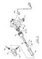
- Figs. 1 to 7 show the convergent spray gun generally illustrated by reference numeral 10 as being comprised of a commercially available Binks gun or of the type of gun described in US 2971700 granted to Peeps on February 14, 1961 entitled “Apparatus For Coating Articles With Chemically Reactive Liquids” generally indicated by reference numeral 12 and modified for meeting the requirements of at least the preferred embodiments of this invention, the dry powder nozzle is indicated by the reference numeral 14 and the concentric tube assembly by the reference numeral 16.
- the commercially available Binks gun which essentially is an L-shaped main body 17 having appropriate passages for flowing the air and resin to a convergent nozzle 19, is modified to include a receiving box 18.
- Receiving box 18 includes fittings for transmitting air into inlet 20 and then into the inlet 21 of the spray gun 10, fittings for transmitting the dry powder into inlet 22 where it is split by any type of splitter (not shown) into two streams for flowing the dry powder through the discharge fittings 23 and 25 and fittings 32 and 34 of dry powder nozzle 14 (see Fig. 2).
- Trigger 30 is suitably mounted adjacent the handle 31 and is conveniently available for operation for actuating the gun to turn the spray of coating on and off.
- the fitting 38 serves to receive the mixed resin which is delivered thereto from a suitable pressurized source and flows through a passage formed in the spray gun 10 and discharges though the central orifice 26, as will be described in detail hereinbelow.
- valve 24 that is manually operated by the trigger 30.
- Valve 24 may be located adjacent to the central orifice 26 discharging the resin, and includes seat 28 surrounding the orifice 26, and valve body 27 connected to the valve stem 29, which is moved rectilinearly by actuation of the trigger 30 for opening and closing the discharge orifice 26 of the spray gun 10.
- the valve 24 may be located adjacent to orifice 40.
- the same or similar parts constituting the valve mechanism would be utilized in this location.
- the dry powder nozzle 14 mounted on the concentric tube assembly 16 includes a pair of diametrically opposed fittings 32 and 34 (see Figure 2) adapted to receive suitable tubing for conveying the dry powder flowing through the fittings into the manifold of the dry powder nozzle that will be described hereinbelow.
- the L-shaped spray gun 10 is capable of being miniaturized from the heretofore known convergent spray guns, not merely because the components are made smaller, which is partially the case, but because of the modification to the Binks type gun and the addition of the inner and outer extension tubes of the concentric tube assembly 16 which will be described in more detail hereinbelow.
- the modified Binks gun 12 includes the central orifice 40 that is fluidly connected to the inlet of the fitting 38 for flowing the resin toward the discharge end of the spray gun.
- the outer tube 42 includes a large diameter hollow conically shaped portion 44 that fairs into a smaller diameter tubular portion 46 that extends axially toward the fore end of the spray gun.
- the aft end of the outer tube 42 is threadably connected to the end of the modified Binks gun by complementary threads 49 so that the cavity 48 defined by the conically shaped large diameter portion 44 surrounds the tip 50 of the modified Binks gun.
- Inner tubular member 58 is threadably attached to the outer tube 44 by complementary threads 52 and, like the tubular portion 46 of the outer tube 42, extends axially toward the tip of the spray gun 10 and lines up with orifice 40 of nozzle 19 to continue the flow of resin toward the central discharge orifice 26.
- the resin is transported toward the tip of the spray gun 10 through the inner tubular member 58 and atomizing air discharging from the circumferentially spaced air discharge holes 60 and 62 of the Binks gun is transported through the outer tubular member 42 via the centrally disposed drilled passages 64 and the annular passage 66.
- the tip of the spray gun 10 is defined by the fluid tip element 70 that includes a central passage 72 terminating in a central discharge orifice 26 and the air cap (which may be a commercially available air cap of the Paasche type), both of which serve to create a conically shaped convergent plume A (see Fig. 4) at the exterior thereof.
- the fluid tip element 70 includes a main body 78 which is circular in cross section and is dimensioned so that its diameter is substantially equal to the inner diameter of the tubular portion 46, and several (up to four) segments or secants to the circular cross section are milled or cut at the larger diameter portion 80 to form flats that leave a gap between the fluid tip element 70 and the annular passage 66 (see Fig. 5). This gap serves to meter, direct and atomize the air in the annular passage 66. As can best be seen in Fig.
- the aft end 82 of the fluid tip element 70 extends axially rearwardly and is threaded to complement the threads formed on the end of the inner tubular member 58 to form a tight fit and communicate the central orifice 84 with the passage 86 formed in the fluid tip element 70 which, in turn, communicates with the passage 68 of the inner tubular member 58 for flowing resin to discharge through central orifice 84.
- Air cap 90 includes a conical inner surface 92 and a threaded aft end 94 that threadably engages the complementary threads formed on the outer end of the outer tubular member 46 and serves to surround the fluid tip element 70.
- the air cap 90 serves to converge the atomized air toward the discharge end of central orifice 84 so as to increase the dynamic head of the resin flowing through passage 68 into the reduced diameter portion of central passage 86 and cause it to be accelerated and expand as it is being discharged.
- the air discharging from the convergent surface 92 of air cap is formed in a highly atomized spray that mixes intensely with the resin as it discharges from orifice 84 and forms a stream of small particles accelerating toward the target.
- the mixed atomized air and resin are discharged so as to define a plume immediately downstream of the central aperture 98 formed in the air cap 90 where the dry powder is injected as will be explained hereinbelow.
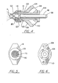
- the dry powder nozzle 14 as shown in Figs. 4 to 6, consists of a main cylindrically shaped body 102 having angularly disposed extension portions 104 and 106, and includes a central straight through bore 109 communicating with the drilled passages 108 and 110 angularly disposed relative thereto formed in the extension portions 104 and 106, respectively.
- the dry powder nozzle 14 is fitted over a sleeve 116 that is concentrically and coaxially disposed relative to the fluid tip 70 and the tubular member 46 and tubular member 58 of the concentric tube assembly 16.
- Convergent cap 120 is frictionally fitted or fitted in any suitable manner at the aft end of the dry powder nozzle cap 14 and includes a nozzle 122 defined by the convergent cap 120 that directs the flow of dry powder from the dry powder nozzle 14 into the plume A (as shown in Fig 3).
- the annular space between the sleeve 116 and the inner diameter of the main body 102 of the dry powder nozzle 14 defines an annular manifold 116 where the powder is transmitted and streamlined just prior to being injected into the low pressure zone of the atomized plume A (Fig. 3).
- the end-effector of at least the preferred embodiments of the present invention functions similarly to the end-effector shown in US 5307992, supra, because of the incorporation of the concentric tube assembly 16, the dry powder nozzle 14 and convergent cap 120 is made significantly smaller than the previous designs while at the same time allowing a comparable volume of flow of the ingredients emitted at the discharge end of the spray gun.
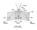
- Fig. 6A exemplifies another embodiment of the dry powder nozzle 14a that includes a central passage 200 for flowing the liquid resin that discharges through central orifice 202, annular air passages 206 that discharge the air through an annular orifice 210 at an angle to converge with and atomize the resin, and diametrically opposed dry powder passages 212 and 214 that directly feed into the low pressure zone of the plume of the atomized air/resin stream.
- the configuration of the dry powder nozzle 14 depicted in Figs. 5 and 6 is designed to accommodate the larger granular sized particles of dry powder, while the dry powder nozzle 14a depicted in Fig. 6A is preferably designed for a finer dry powder granular.
- suitable commercially available hose 124 interconnects the spray gun 10 to a high pressurized air source 134 via the receiving box 18.
- the powder and low pressure air for transporting the same is represented by box 136 which is also transported to the spray gun 10 via receiving box 18 where it is split and transported to the dry powder nozzle 14 or 14a.
- the static mixer 138 (which may be a suitable Hirsch tube) supplies the resin (which in this embodiment is made from two components, resin and catalyst) to the spray gun 10 via line 128.
- the catalyst and resin are admitted into mixer 138 from manifold 143 which receives these components through lines 139 and 141, respectively.
- a proximity switch 146 may be added for connection to a shut-down system 148.
- the miniaturized gun 10 is sufficiently small and light in weight so as to be easily handled by a user, much in the same manner that a commercially available powered paint spray gun is used.
- Actuation of the trigger 30 opens or closes valve 24 and turns on the computer, valves, proportioning devices, pneumatic devices, for flowing and stopping the flow of the ingredients being delivered to the gun.
- a solvent in reservoir 151 is admitted into the resin flow lines via the mixer 138 through line 147 and a suitable on/off valve 149.
- the solvent is admitted into the manifold 143 and flows through the resin lines in the gun to ensure that the resin that is captured therein when the gun is shut off does not cure and become hardened.
- the volume of ingredients emitted from the gun corresponds to the larger and heavier convergent spray guns that are known.
- the spray gun made in accordance with at least the preferred embodiments of this invention is not only capable of being hand-held but is also capable of applying thermal protection coatings with the absence of a solvent, and is compatible with epoxy, polyurethane, silicate, water based or 100% resin systems, and has the capability of controlling the thickness and the dimensions of the area of the applied coatings, has the ability to control both dry filler and resin filled material independently, to apply the coatings to smaller parts and enclosures and is capable of reducing the number of passes to attain the desired thickness of the coating, while at the same time reduce the amount of hazardous materials and solvents while being capable of controlling density.
- Fig. 8 exemplifies another embodiment of this invention and shows a prototype of a modified robotically held spray gun that is miniaturized so as to be capable of being hand-held, similar to the version depicted in Figs. 1 to 7 and which may be used in a portable system.
- the spray gun which is generally indicated by reference numeral 160, and which as mentioned above is a prototype of a spray gun which is miniaturized for hand-held operation or for a portable system, includes a modified Binks gun 162 that is commercially available, an air motor 164, a paddle mixer 166 and the concentric tube assembly 168, the fluid tip 70 (like reference numerals used in all the Figures depict like or similar elements), air cap 90, and the dry powder nozzle 14.
- a paddle mixer 166 is utilized instead of the static mixer disposed upstream of the spray gun 10 as shown in Figs. 1 to 7 being utilized.
- the paddle mixer 166 is driven by the air motor of the Binks gun, which is powered by the pressurized air flowing into the gun through inlet 170 and discharging through the outlet 172, and mixes the resin (double type) fed thereto through inlet fittings 174 and 176.
- the mixed resin after being acted on by the paddled mixer 166 flows through the housing 178, cross-over tube 180 and into the inner tubular member 182 and discharges through the central orifice 26 formed on the end of the fluid tip 70.
- Air cap 90 which fits over the fluid tip 70, receives pressurized air from the inlet 182, which flows through inner passages formed in the housing 178 into the cross-over tube 185 and into the annular passage formed between the inner diameter of outer tubular member 186 and the outer diameter of inner tubular member 182.
- the dry powder nozzle 14 fits over the end of the reduced diameter portion of outer tubular member 186 and injects the dry powder from the manifold and convergent cap 120 into the wetted resin atomized plume A (similar to Fig. 4).
- the spray gun operates in much the same way as the version in Figs.
- the version of the spray gun exemplified in Fig. 9 is a combination of the elements that constitute the spray gun depicted in Figs 1 and 8, where the Binks gun and Paache tubes are modified to miniaturize the spray gun.
- the spray gun is better suited for use with the robot.
- the spray gun is more appealing for use in a portable spray system rather than the separate room arrangement that is typical for this type of coating application.
- the spray gun utilizes a commercially available Binks gun 162a with all of the same flow passages for the air and resin, and includes a similar paddle mixer 166a.
- This Binks gun is modified to include an air conduit 220 that interconnects the air passage in the Binks gun with a manifold 224 that is mounted on the end of the paddle mixer 166a.
- the manifold directs the air around the resin without co-mingling therewith and flows in the outer tube of the double tube configuration 16a.
- This portion of the gun is virtually identical to the forward portion of the spray gun depicted in Figs. 2, 3 and 4 and reference should be made thereto for details of the components thereof.
- the unit comprises the double concentric tubes 16a for passing the resin and air to the discharge nozzle of the spray gun through the fluid tip element 70a and into the air cap 90a.
- the dry powder nozzle configuration depicted in Fig. 6A can be substituted for the dry powder nozzle 14 depicted in this embodiment.
Description
- This invention relates to portable convergent spray guns for applying coatings to a surface, and particularly to a portable spray gun that is miniaturized so as to be capable of being hand-held, or having the option of being either hand-held or robotically-held for use with a portable system.
- Portable spray guns for spraying resin or the like commonly include a handle portion having a first central passage for flowing a first material, such as a liquid resin, and a first concentric passage for flowing pressurized air, and a nozzle internal of said spray gun for discharging the resin from the central passage. A spray gun comprising the features of the preamble of claim 1 is disclosed in US 3185396.
- US 5565241 granted to Mathias et al on October 15, 1996 entitled "Convergent End Effector", and US 5579998 granted to Hall et al on December 3, 1996 entitled "Method For Coating A Substrate With A Reinforced Resin Matrix", of which the inventor Jack G. Scarpa is a co-inventor and which patents are assigned to the current applicant, both disclose a spray gun with a nozzle that is designed to configure the spray emitted by the nozzle into an atomized convergent plume of liquid resin and target the plume with reinforced filler material downstream of the nozzle to mix and wet the filler just prior to being applied to the surface of the substrate. In other words the reinforcing material is entrained around the atomized liquid resin flow and is caused to be captured thereby, mix therewith and become a homogeneously wetted coating material that after impact with the substrate becomes cured into a substantially reasonably thick coating exhibiting good strength and resistance characteristics. The gaseous transport stream together with the eductor deliver the ingredients in the proper proportions and the air stream for causing the atomization and mixing to provide the proper amounts of material to assure that the coating is uniform and consistent. Heating is applied in the proper sequence to ensure that the viscosity is at the proper level to assure evenness of flow and better atomization.
- As one skilled in this technology would appreciate, the heretofore known spray application equipment for spraying of highly loaded paints and coatings which require the addition of a high volume of solid large granular materials such as cork, glass microspheres, granular or powdered materials in the 3 to 300 µm range require large amounts of solvents to dilute solid contents down to a level where it can be sprayed effectively. This, of necessity, requires special spray equipment designs that need to be significantly large in order to effectively spray these materials. Such systems have heretofore been designed to operate in a room or compartment including a robot programmed to hold the spray gun and apply the spray. An additional room housed the supply of materials to be mixed and sprayed, the various valves, hoppers, proportioning devices and the like and separated from these rooms was a room that housed the computer equipment that served to control the various valves, proportioning devices etc, to automatically effectuate the spraying.
- European patent application No. 98310460.5, published as EP 0925843 A2, exemplifies a convergent spray gun that is made into a portable unit. Like the spray guns described in the aforementioned patents which are typically held by a robot, it, likewise, is very large and as a matter of fact requires the spray apparatus to be formed as part of a wand that requires two hands to operable effectively.
- These special very large spray equipment designs lead to very low actual transfer efficiencies for spraying these coating materials. These low transfer efficiencies have a significant impact on the quantities of materials, solvents and volatile organic compounds that are released into the environment. As one skilled in this technology will appreciate, from an ecology standpoint these conditions are not preferred as is recognized by the Environmental Protection Agency and Occupational Safety and Health Administrations that are tightening regulations that mandate change.
- One would normally expect that in order to reduce the size of the gun and attain all of the features and particularly be able to apply the same amount of coating for each pass, one would merely have to reduce the size of each of the components of the heretofore known guns as for example, of the type exemplified in the aforementioned patents. However, merely reducing the size of the components will not realize a convergent spray gun that will effectively spray a coating, and as a matter of fact such a design fails to meet the specifications for coatings that are required in the larger guns that are exemplified by the aforementioned patents and patent application. As a matter of fact, it has been found that it was necessary to add additional components in order to reduce the overall size and weight of the gun so that it could be hand-held, that is, held by one hand in the same way that a commercially available paint spray gun is handled.
- According to the invention, the spray gun is characterized in that the spray gun also includes a double concentric tube assembly having a second central passage in axial alignment with said first central passage for receiving said resin from said internal nozzle, a second concentric passage in axial alignment with said first concentric passage, a fluid tip mounted on the end of said second central passage defining a central orifice for discharging the resin flowing from said first central passage and said second central passage, an air cap mounted over said fluid tip and defining therewith an air nozzle for flowing air into said resin stream discharging from said central orifice and defining an atomized convergent spray having a low pressure zone, and a nozzle for a dry powder, said nozzle having angled flow passages for directing said dry powder into the low pressure zone of said atomized convergent spray.
- This aspect of the invention contemplates adding a concentric tube construction to the commercially available (modified to meet the needs of the present invention) spray nozzle, such as spray nozzles produced by Binks, Franklin Park, Illinois, USA and Graco, Detroit, Michigan, USA, that provides an inner tube that transports the resin, an outer tube that transports the air for atomizing the mixture, and the dry powder nozzle and its convergent cap. This arrangement of the concentric tubes allows the dry powder nozzle that transports the dry powder material into a manifold to be propelled into the resin/air atomization plume. The dry granular materials and atomized resins become entrained at this point and thoroughly mix together outside the gun before being deposited on the substrate.
- As is the case of the structure in US 5307992 granted to Hall et al on May 3, 1994 entitled "Method And System For Coating A Substrate With A Reinforced Resin Matrix" and assigned to the current application, and US 5565241 and US 5579998, supra, the preferred embodiments of the invention described in this patent application do not change the basic operation principles but provide a mini-gun that is capable of being hand-held for coating operations and is an improvement in ergonomic design over heretofore convergent types of guns. As mentioned above, the gun made in accordance with the preferred embodiments of this invention is also capable of use in a fully robotically automated system of the type already in operation and also can be used for incorporation for completely portable convergent nozzle spray gun systems.
- Advantageously, and not by way of limitation, at least the preferred embodiments of the present invention afford the following features:
- 1) Solventless application of thermal protection coatings;
- 2) Compatibility with solvent borne epoxy, polyurethane, silicate, water-based or 100% solid resin systems;
- 3) Ability to accurately control thickness of applied coatings by robotics or hand-held;
- 4) Ability to control dimensions of area to be coated;
- 5) Ability to control both dry filler and resin filled material independently;
- 6) Enhanced ability to apply coatings to smaller parts and enclosures;
- 7) Ability to reduce the required passes to attain the desired thickness;
- 8) Significant reduction in waste and hazardous materials;
- 9) Significant reduction in solvents; and
- 10) Ability to control density.
- An object of at least the preferred embodiments of this invention is to provide an improved mini-convergent spray gun that is characterized as being capable of being held in the user's hand.
- A feature of the preferred embodiments of this invention is that it incorporates a concentric tube assembly communicating with a commercially available spray gun that transports the resin and air to a reduced sized dry powder nozzle and convergent end-effector for injecting a dry powder in the convergent atomized resin spray at the exterior of the resin discharge orifice.
- A still further object of the preferred embodiments of this invention is to provide a convergent type of spray gun that is capable of being hand-held, that is characterized as being capable of applying thermal protection coatings with the absence of a solvent, and is compatible with epoxy, silicone, polyurethane, silicate, water based or 100% resin systems; has the capability of controlling the thickness and the dimensions of the area of the applied coatings; has the ability to control both dry filler and resin filled material independently; to apply the coatings to smaller parts and enclosure and reduce the number of passes to attain the desired thickness of the coating, reduce the amount of hazardous materials and solvents while being capable of controlling density.
- Preferred embodiments of the present invention will now be described by way of example only and with reference to the attached drawings, in which:
- Fig. 1 is a perspective view of a first embodiment of a miniaturized spray gun of this invention;
- Fig. 2 is an exploded view showing the component parts of the spray gun of Fig. 1;
- Fig. 3 is a diagrammatic view in section of the concentric tube assembly;
- Fig. 4 is a partial view partly in section and partly in elevation taken along the longitudinal axis of the concentric tubes of Fig. 1:
- Fig. 5 is plan view of the front end of the dry powder nozzle of the spray gun depicted in Fig. 1;
- Fig. 6 is a plan view of the aft end of the dry powder nozzle of the spray gun depicted in Fig. 1;
- Fig. 6A is a is a sectional view of an alternate embodiment of the dry powder nozzle for use with the spray gun depicted in Fig. 1;
- Fig. 7 is a perspective view of the spray gun depicted in Fig. 1 and a schematic illustration of the system utilized therewith;
- Fig. 8 shows another embodiment of the invention, in the form of an exploded view of a prototype portable miniaturized convergent spray gun configuration; and
- Fig. 9 shows an alternate embodiment of the portable spray gun, substantially the same as the embodiment depicted in Fig. 8 save for the fact that this alternate embodiment is straight through.
- These figures merely serve to further clarify and illustrate the present invention and are not intended to limit the scope thereof.
- As noted in the above paragraphs, the system for supplying the desired ingredients for the coating is described in US 5307992, supra, and the system for supplying these ingredients to the spray gun of the current application is substantially the same. In one version, the resin and catalysts (resin) are mixed in a paddled mixer that is disposed in the gun, and in the other version the resin and catalyst are mixed in a static mixer disposed upstream of the spray gun. Both systems will be more fully described hereinbelow. The dry materials such as cork or glass microspheres are transported by a controlled dry hopper loss-in-weight or mass loss feeding system that feeds into educted pneumatic tubes that transports the material to a cyclonic mixer and then to the convergent end-effector nozzle. The wet epoxy resin material such as 3M 2216 which is commercially available or other suitable epoxy or polyurethane systems of various ratio is transported by means of pressure pots. The components of the resin are regulated to a desired ratio by a suitable commercially available proportioning system. Such systems are available, for example, from the Zenith Pump division of Parker Hannifin Corporation of Sanford, North Carolina or from the Moyno division of Robin & Myer of Dayton, Ohio. These proportioning systems or any other type of commercially available proportioning systems that are usable in this system are designed to proportion the two components of the resin and meter the same to a suitable mixer either of the dynamic or static type prior to being flowed to the discharge nozzles of the spray gun. The system serves to control all the valves, air and resin flows by a suitable analogue panel which is controlled by a suitable I/O control processor of a general purpose type of computer. To better understand this invention the nomenclature of the component parts are defined as follows:
- "convergent end effector nozzle" is the discharge end of the gun where the resin and air are atomized and converged and the dry powder is introduced through the dry powder nozzle.
- "dry powder nozzle" is the nozzle that feeds the dry powder into the plume of the atomized resin.
- "convergent cap" is the cap mounted on the end of the dry powder nozzle that defines the discharge orifice.
- "nozzle" is any discharge orifice that discharges flow in a prescribed manner.
- Referring now to Figs. 1 to 7, which show the convergent spray gun generally illustrated by
reference numeral 10 as being comprised of a commercially available Binks gun or of the type of gun described in US 2971700 granted to Peeps on February 14, 1961 entitled "Apparatus For Coating Articles With Chemically Reactive Liquids" generally indicated byreference numeral 12 and modified for meeting the requirements of at least the preferred embodiments of this invention, the dry powder nozzle is indicated by thereference numeral 14 and the concentric tube assembly by thereference numeral 16. The commercially available Binks gun, which essentially is an L-shaped main body 17 having appropriate passages for flowing the air and resin to aconvergent nozzle 19, is modified to include areceiving box 18. Receivingbox 18 includes fittings for transmitting air intoinlet 20 and then into theinlet 21 of thespray gun 10, fittings for transmitting the dry powder intoinlet 22 where it is split by any type of splitter (not shown) into two streams for flowing the dry powder through thedischarge fittings fittings Trigger 30 is suitably mounted adjacent thehandle 31 and is conveniently available for operation for actuating the gun to turn the spray of coating on and off. The fitting 38 serves to receive the mixed resin which is delivered thereto from a suitable pressurized source and flows through a passage formed in thespray gun 10 and discharges though thecentral orifice 26, as will be described in detail hereinbelow. In addition to the modification of the Binks gun described above, there is a fluid tip of the type known as a Paasche tip that is commercially available and as best seen in Fig. 3 is designed to includevalve 24 that is manually operated by thetrigger 30.Valve 24 may be located adjacent to thecentral orifice 26 discharging the resin, and includesseat 28 surrounding theorifice 26, andvalve body 27 connected to thevalve stem 29, which is moved rectilinearly by actuation of thetrigger 30 for opening and closing thedischarge orifice 26 of thespray gun 10. Alternatively, thevalve 24 may be located adjacent toorifice 40. In the alternative embodiment the same or similar parts constituting the valve mechanism would be utilized in this location. - Referring next to Figs. 4 to 6, the
dry powder nozzle 14 mounted on theconcentric tube assembly 16 includes a pair of diametricallyopposed fittings 32 and 34 (see Figure 2) adapted to receive suitable tubing for conveying the dry powder flowing through the fittings into the manifold of the dry powder nozzle that will be described hereinbelow. - As was mentioned above, the L-shaped
spray gun 10 is capable of being miniaturized from the heretofore known convergent spray guns, not merely because the components are made smaller, which is partially the case, but because of the modification to the Binks type gun and the addition of the inner and outer extension tubes of theconcentric tube assembly 16 which will be described in more detail hereinbelow. As best seen in Fig. 3, the modifiedBinks gun 12 includes thecentral orifice 40 that is fluidly connected to the inlet of the fitting 38 for flowing the resin toward the discharge end of the spray gun. Theouter tube 42 includes a large diameter hollow conically shapedportion 44 that fairs into a smallerdiameter tubular portion 46 that extends axially toward the fore end of the spray gun. The aft end of theouter tube 42 is threadably connected to the end of the modified Binks gun bycomplementary threads 49 so that thecavity 48 defined by the conically shapedlarge diameter portion 44 surrounds thetip 50 of the modified Binks gun. Innertubular member 58 is threadably attached to theouter tube 44 bycomplementary threads 52 and, like thetubular portion 46 of theouter tube 42, extends axially toward the tip of thespray gun 10 and lines up withorifice 40 ofnozzle 19 to continue the flow of resin toward thecentral discharge orifice 26. As is apparent from the foregoing and from Figure 3, the resin is transported toward the tip of thespray gun 10 through theinner tubular member 58 and atomizing air discharging from the circumferentially spaced air discharge holes 60 and 62 of the Binks gun is transported through the outertubular member 42 via the centrally disposed drilledpassages 64 and theannular passage 66. The tip of thespray gun 10 is defined by thefluid tip element 70 that includes a central passage 72 terminating in acentral discharge orifice 26 and the air cap (which may be a commercially available air cap of the Paasche type), both of which serve to create a conically shaped convergent plume A (see Fig. 4) at the exterior thereof. Thefluid tip element 70 includes amain body 78 which is circular in cross section and is dimensioned so that its diameter is substantially equal to the inner diameter of thetubular portion 46, and several (up to four) segments or secants to the circular cross section are milled or cut at thelarger diameter portion 80 to form flats that leave a gap between thefluid tip element 70 and the annular passage 66 (see Fig. 5). This gap serves to meter, direct and atomize the air in theannular passage 66. As can best be seen in Fig. 3, theaft end 82 of thefluid tip element 70 extends axially rearwardly and is threaded to complement the threads formed on the end of theinner tubular member 58 to form a tight fit and communicate thecentral orifice 84 with thepassage 86 formed in thefluid tip element 70 which, in turn, communicates with thepassage 68 of theinner tubular member 58 for flowing resin to discharge throughcentral orifice 84. -
Air cap 90 includes a conicalinner surface 92 and a threadedaft end 94 that threadably engages the complementary threads formed on the outer end of the outertubular member 46 and serves to surround thefluid tip element 70. Theair cap 90 serves to converge the atomized air toward the discharge end ofcentral orifice 84 so as to increase the dynamic head of the resin flowing throughpassage 68 into the reduced diameter portion ofcentral passage 86 and cause it to be accelerated and expand as it is being discharged. The air discharging from theconvergent surface 92 of air cap is formed in a highly atomized spray that mixes intensely with the resin as it discharges fromorifice 84 and forms a stream of small particles accelerating toward the target. The mixed atomized air and resin are discharged so as to define a plume immediately downstream of the central aperture 98 formed in theair cap 90 where the dry powder is injected as will be explained hereinbelow. - The
dry powder nozzle 14, as shown in Figs. 4 to 6, consists of a main cylindrically shapedbody 102 having angularly disposedextension portions 104 and 106, and includes a central straight throughbore 109 communicating with the drilledpassages extension portions 104 and 106, respectively. Thedry powder nozzle 14 is fitted over asleeve 116 that is concentrically and coaxially disposed relative to thefluid tip 70 and thetubular member 46 andtubular member 58 of theconcentric tube assembly 16.Convergent cap 120 is frictionally fitted or fitted in any suitable manner at the aft end of the drypowder nozzle cap 14 and includes anozzle 122 defined by theconvergent cap 120 that directs the flow of dry powder from thedry powder nozzle 14 into the plume A (as shown in Fig 3). The annular space between thesleeve 116 and the inner diameter of themain body 102 of thedry powder nozzle 14 defines anannular manifold 116 where the powder is transmitted and streamlined just prior to being injected into the low pressure zone of the atomized plume A (Fig. 3). These elements just described, namely theair cap 92,fluid tip 70 anddry powder nozzle 14, form the end-effector of the convergent spray gun. While the end-effector of at least the preferred embodiments of the present invention functions similarly to the end-effector shown in US 5307992, supra, because of the incorporation of theconcentric tube assembly 16, thedry powder nozzle 14 andconvergent cap 120 is made significantly smaller than the previous designs while at the same time allowing a comparable volume of flow of the ingredients emitted at the discharge end of the spray gun. - Fig. 6A exemplifies another embodiment of the
dry powder nozzle 14a that includes acentral passage 200 for flowing the liquid resin that discharges throughcentral orifice 202,annular air passages 206 that discharge the air through anannular orifice 210 at an angle to converge with and atomize the resin, and diametrically opposed dry powder passages 212 and 214 that directly feed into the low pressure zone of the plume of the atomized air/resin stream. It will be appreciated that the configuration of thedry powder nozzle 14 depicted in Figs. 5 and 6 is designed to accommodate the larger granular sized particles of dry powder, while thedry powder nozzle 14a depicted in Fig. 6A is preferably designed for a finer dry powder granular. - In operation, and as seen in Fig.7, suitable commercially
available hose 124 interconnects thespray gun 10 to a highpressurized air source 134 via thereceiving box 18. The powder and low pressure air for transporting the same is represented bybox 136 which is also transported to thespray gun 10 via receivingbox 18 where it is split and transported to thedry powder nozzle spray gun 10 vialine 128. The catalyst and resin are admitted intomixer 138 frommanifold 143 which receives these components throughlines proximity switch 146 may be added for connection to a shut-downsystem 148. - The miniaturized
gun 10 is sufficiently small and light in weight so as to be easily handled by a user, much in the same manner that a commercially available powered paint spray gun is used. Actuation of thetrigger 30 opens or closesvalve 24 and turns on the computer, valves, proportioning devices, pneumatic devices, for flowing and stopping the flow of the ingredients being delivered to the gun. A solvent inreservoir 151 is admitted into the resin flow lines via themixer 138 throughline 147 and a suitable on/off valve 149. The solvent is admitted into the manifold 143 and flows through the resin lines in the gun to ensure that the resin that is captured therein when the gun is shut off does not cure and become hardened. - As mentioned in the above paragraphs, the volume of ingredients emitted from the gun corresponds to the larger and heavier convergent spray guns that are known. The spray gun made in accordance with at least the preferred embodiments of this invention is not only capable of being hand-held but is also capable of applying thermal protection coatings with the absence of a solvent, and is compatible with epoxy, polyurethane, silicate, water based or 100% resin systems, and has the capability of controlling the thickness and the dimensions of the area of the applied coatings, has the ability to control both dry filler and resin filled material independently, to apply the coatings to smaller parts and enclosures and is capable of reducing the number of passes to attain the desired thickness of the coating, while at the same time reduce the amount of hazardous materials and solvents while being capable of controlling density.
- Fig. 8 exemplifies another embodiment of this invention and shows a prototype of a modified robotically held spray gun that is miniaturized so as to be capable of being hand-held, similar to the version depicted in Figs. 1 to 7 and which may be used in a portable system. The spray gun, which is generally indicated by
reference numeral 160, and which as mentioned above is a prototype of a spray gun which is miniaturized for hand-held operation or for a portable system, includes a modifiedBinks gun 162 that is commercially available, anair motor 164, apaddle mixer 166 and theconcentric tube assembly 168, the fluid tip 70 (like reference numerals used in all the Figures depict like or similar elements),air cap 90, and thedry powder nozzle 14. Instead of the static mixer disposed upstream of thespray gun 10 as shown in Figs. 1 to 7 being utilized, in this version apaddle mixer 166 is utilized. However, it should be noted that either version of the spray guns may utilize either type of mixer. Thepaddle mixer 166 is driven by the air motor of the Binks gun, which is powered by the pressurized air flowing into the gun throughinlet 170 and discharging through theoutlet 172, and mixes the resin (double type) fed thereto throughinlet fittings mixer 166 flows through thehousing 178,cross-over tube 180 and into the innertubular member 182 and discharges through thecentral orifice 26 formed on the end of thefluid tip 70.Air cap 90, which fits over thefluid tip 70, receives pressurized air from theinlet 182, which flows through inner passages formed in thehousing 178 into thecross-over tube 185 and into the annular passage formed between the inner diameter of outertubular member 186 and the outer diameter of innertubular member 182. Thedry powder nozzle 14 fits over the end of the reduced diameter portion of outertubular member 186 and injects the dry powder from the manifold andconvergent cap 120 into the wetted resin atomized plume A (similar to Fig. 4). The spray gun operates in much the same way as the version in Figs. 1 to 7, where the operator depresses a suitable switch that actuates the system of valves, proportioning devices, eductors, and pneumatic conveying equipment controlled by the computer which turns the system on and off. Turning the system on flows the proper proportion of resin, dry powder, atomizing air and pressurized motor air to thegun 160 for actuating thepaddle mixer 166 and the valves in the gun to generate the atomized convergent plume of wetted resin and drive the dry powder nozzle to inject the dry powder into the plume in the manner described in connection with the spray gun depicted in Figs. 1 to 7. - The version of the spray gun exemplified in Fig. 9 is a combination of the elements that constitute the spray gun depicted in Figs 1 and 8, where the Binks gun and Paache tubes are modified to miniaturize the spray gun. Obviously, because the handle takes the elongated shape rather than the pistol shape, the spray gun is better suited for use with the robot. However, since the parts are miniaturized, the spray gun is more appealing for use in a portable spray system rather than the separate room arrangement that is typical for this type of coating application. In the Fig. 9 version, the spray gun utilizes a commercially available Binks gun 162a with all of the same flow passages for the air and resin, and includes a similar paddle mixer 166a. This Binks gun is modified to include an air conduit 220 that interconnects the air passage in the Binks gun with a manifold 224 that is mounted on the end of the paddle mixer 166a. The manifold directs the air around the resin without co-mingling therewith and flows in the outer tube of the double tube configuration 16a. This portion of the gun is virtually identical to the forward portion of the spray gun depicted in Figs. 2, 3 and 4 and reference should be made thereto for details of the components thereof. The unit comprises the double concentric tubes 16a for passing the resin and air to the discharge nozzle of the spray gun through the fluid tip element 70a and into the air cap 90a. The sleeve 116a that fits over the double concentric tubes 16a, fluid tip element 70a and air cap 90a accommodates the
dry powder nozzle 14a for passing the dry powder into the atomized air/resin stream discharging from the tip of the spray gun. Like in the other spray gun versions the dry powder nozzle configuration depicted in Fig. 6A can be substituted for thedry powder nozzle 14 depicted in this embodiment. - Although this invention has been shown and described with respect to detailed preferred embodiments thereof, it will be appreciated and understood by those skilled in the art that various changes in form and detail thereof may be made without departing from the scope of the claimed invention.
Claims (10)
- A portable convergent spray gun (10) including a handle portion (31) having a first central passage (40) for flowing a liquid resin and a first concentric passage (62) for flowing pressurized air, and a nozzle (50) internal of said spray gun for discharging the liquid resin from the first central passage (40),wherein the spray gun also includes a double concentric tube assembly (42) having a second central passage (68) in axial alignement with said first central passage (40) for receiving resin from said internal nozzle (50), a second concentric passage (66) in axial alignment with said first concentric passage (62), a fluid tip (70) mounted on the end of said second central passage (68) defining a central orifice (26) for discharging the resin flowing from said first central passage (40) and said second central passage (68), characterized by an air cap (90) mounted over said fluid tip (70) and defining therewith an air nozzle for flowing air into said resin stream discharging from said central orifice (26) and defining an atomized convergent spray having a low pressure zone, and a nozzle (14) for a dry powder, said nozzle (14) having angled flow passages (108, 110) for directing said dry powder into the low pressure zone of said atomized convergent spray.
- A spray gun as claimed in claim 1, including a sleeve (116) surrounding said double concentric tube assembly (42) and defining a manifold, said dry powder nozzle (14) including diametrically opposed passages (108, 110) disposed relative to said second central passage communicating with said manifold for leading dry powder from said diametrically opposed passages to the orifice formed on the end of said dry powder nozzle (14) and directing said dry powder to the low pressure zone.
- A spray gun as claimed in claim 1, wherein said dry powder nozzle (14) includes diametrically opposed passages (108, 110) disposed relative to said second central passage for directing said dry powder directly into the low pressure zone.
- A spray gun as claimed in any preceding claim, wherein said spray gun includes a main body, said main body being generally L-shaped.
- A spray gun as claimed in claim 4, including a receiving box (18) attached to said handle portion for receiving the dry powder and low pressure air for directing said dry powder into said diametrically opposed passages (108, 110).
- A spray gun as claimed in claim 5, including a mixer (138) disposed downstream of said main body, a source of said resin and a source of catalyst, a manifold (143), connection means for interconnecting said manifold with said source of said resin and said source of catalyst to said mixer and a hose interconnecting said mixer with said spray gun.
- A spray gun as claimed in claim 6, including a valve (24) operatively connected to said second central passage for flowing and stopping the flow of said first material.
- A spray gun as claimed in claim 1, having a straight-through main body, a mixer in said main body having a plurality of paddles, said mixer being in communication with said first central passage for mixing the resin and catalyst, and being connected to said second central passage.
- A spray gun as claimed in claim 8, including a sleeve (186) surrounding said double concentric tube assembly and defining a manifold, said dry powder nozzle (14) including diametrically opposed passages disposed relative to said second central passage communicating with said manifold for leading said dry powder from said diametrically opposed passages to the orifice formed on the end of said dry powder nozzle (14) and directing said dry powder to the low pressure zone.
- A spray gun as claimed in claim 8, wherein said dry powder nozzle (14) includes diametrically opposed passages disposed relative to said second central passage for directing said dry powder directly into the low pressure zone.
Applications Claiming Priority (2)
| Application Number | Priority Date | Filing Date | Title |
|---|---|---|---|
| US394289 | 1999-09-10 | ||
| US09/394,289 US6892963B1 (en) | 1999-09-10 | 1999-09-10 | Portable convergent spray gun capable of being hand-held |
Publications (3)
| Publication Number | Publication Date |
|---|---|
| EP1083000A2 EP1083000A2 (en) | 2001-03-14 |
| EP1083000A3 EP1083000A3 (en) | 2003-04-23 |
| EP1083000B1 true EP1083000B1 (en) | 2007-05-30 |
Family
ID=23558325
Family Applications (1)
| Application Number | Title | Priority Date | Filing Date |
|---|---|---|---|
| EP00307715A Expired - Lifetime EP1083000B1 (en) | 1999-09-10 | 2000-09-06 | Portable convergent spray gun |
Country Status (5)
| Country | Link |
|---|---|
| US (3) | US6892963B1 (en) |
| EP (1) | EP1083000B1 (en) |
| JP (1) | JP2001096204A (en) |
| CA (1) | CA2317851A1 (en) |
| DE (1) | DE60035004D1 (en) |
Families Citing this family (34)
| Publication number | Priority date | Publication date | Assignee | Title |
|---|---|---|---|---|
| US6892963B1 (en) * | 1999-09-10 | 2005-05-17 | Usbi Co | Portable convergent spray gun capable of being hand-held |
| US20040216494A1 (en) * | 2000-09-19 | 2004-11-04 | Shinichi Kurotani | Burner for combustion or flame hydrolysis, and combustion furnace and process |
| AUPS275302A0 (en) | 2002-05-31 | 2002-06-27 | Khouri, Anthony | Vehicle mounted concrete mixing drum and method of manufacture thereof |
| US7410674B2 (en) * | 2002-09-30 | 2008-08-12 | General Electric Company | Method of servicing an electro-dynamic apparatus |
| US6811096B2 (en) * | 2002-12-30 | 2004-11-02 | Aqua Glass Corporation | Spray gun with internal mixing structure |
| US8287173B2 (en) | 2003-08-15 | 2012-10-16 | Mcneilus Truck And Manufacturing, Inc. | Mixing drum hatch |
| AU2003256432B2 (en) | 2003-08-15 | 2009-12-10 | Composite Technology R & D Pty Limited | Mixing drum |
| EP1660289A4 (en) | 2003-08-15 | 2009-01-07 | Mc Neilus Truck & Mfg Inc | Mixing drum blade |
| CA2558018C (en) | 2004-03-04 | 2013-03-26 | Mcneilus Truck And Manufacturing, Inc. | Mixing drum |
| US7850364B2 (en) | 2004-05-18 | 2010-12-14 | Mcneilus Truck And Manufacturing, Inc. | Concrete batch plant with polymeric mixer drum |
| US20060071097A1 (en) * | 2004-09-24 | 2006-04-06 | Southwest Research Institute | Systems and methods for dispensing an anti-traction, mobility denial material |
| US20060163324A1 (en) * | 2005-01-27 | 2006-07-27 | Honeywell International, Inc. | Method and system for spraying metallic powder on a component surface |
| FR2886325B1 (en) * | 2005-05-30 | 2008-05-30 | Charline Marie Henriet Lemaire | CONTROLLED INJECTION PISTOL OF CLAMS IN LOCAL AREAS OF WORKS HAVING WATER SEALING DEFECTS |
| US20070074656A1 (en) | 2005-10-04 | 2007-04-05 | Zhibo Zhao | Non-clogging powder injector for a kinetic spray nozzle system |
| US20070187434A1 (en) * | 2006-02-10 | 2007-08-16 | Mcneilus Truck And Manufacturing, Inc. | Applicator system |
| US7726589B2 (en) * | 2006-05-18 | 2010-06-01 | Georgio Roumanis | Hand held dual nozzle spray gun and system |
| US20080011333A1 (en) * | 2006-07-13 | 2008-01-17 | Rodgers Michael C | Cleaning coating dispensers |
| WO2008073110A1 (en) * | 2006-12-15 | 2008-06-19 | Doben Limited | Gas dynamic cold spray unit |
| US20080249788A1 (en) * | 2007-04-05 | 2008-10-09 | Stephen Heller | Method for developing an objective opinion |
| US20100308134A1 (en) * | 2009-06-03 | 2010-12-09 | Michael Bunnell | Automatic Paint Spray Gun For Two-Component Systems |
| US8652581B2 (en) * | 2009-10-09 | 2014-02-18 | Matthew Merchant | Method of using a spray gun and material produced thereby |
| US8939387B2 (en) * | 2010-05-03 | 2015-01-27 | Chapin Manufacturing, Inc. | Spray gun |
| ES2699955T3 (en) * | 2011-05-23 | 2019-02-13 | Sulzer Mixpac Ag | Combination of a static spray mixer with an intermediate piece |
| EP2650052B2 (en) * | 2012-04-13 | 2021-01-27 | J. Wagner AG | Powder beaker spray gun and spray coating device with same |
| CN103044133B (en) * | 2012-12-10 | 2014-08-20 | 金正大生态工程集团股份有限公司 | Controlled-release fertilizer resin and curing agent continuous mixer and working method thereof |
| WO2014089697A1 (en) * | 2012-12-11 | 2014-06-19 | Équipement De Finition Du Québec Inc. | Two component external mix spray gun and pressure system |
| USD744563S1 (en) * | 2014-09-22 | 2015-12-01 | Victor Equipment Company | Two-piece nozzle assembly base component |
| USD744564S1 (en) * | 2014-09-22 | 2015-12-01 | Victor Equipment Company | Two-piece nozzle assembly nose component |
| USD744561S1 (en) * | 2014-09-22 | 2015-12-01 | Victor Equipment Company | Tapered nozzle assembly |
| USD744562S1 (en) * | 2014-09-22 | 2015-12-01 | Victor Equipment Company | Two-piece nozzle assembly |
| USD763935S1 (en) * | 2014-10-31 | 2016-08-16 | Victor Equipment Company | Heavy duty nozzle |
| USD763816S1 (en) * | 2014-10-31 | 2016-08-16 | Victor Equipment Company | Medium duty nozzle |
| CN111013847B (en) * | 2019-12-10 | 2021-01-01 | 江苏浪势塑粉有限公司 | Spray gun device of coating spraying machine with low splashing rate |
| CN113477430B (en) * | 2021-07-06 | 2023-12-12 | 浙江小伦智能制造股份有限公司 | Atomization spray gun capable of preventing whiskers from being formed |
Family Cites Families (36)
| Publication number | Priority date | Publication date | Assignee | Title |
|---|---|---|---|---|
| US1779849A (en) * | 1924-05-17 | 1930-10-28 | Brogdex Co | Atomizing and spraying device |
| US1897173A (en) * | 1931-04-29 | 1933-02-14 | Binks Mfg Co | Air nozzle for spray appliances |
| US2052622A (en) * | 1933-08-05 | 1936-09-01 | William B Hale | Air-jet cleaning and painting device |
| US2276237A (en) * | 1941-03-21 | 1942-03-10 | Dow Chemical Co | Apparatus for mixing cement |
| US2388517A (en) * | 1943-03-06 | 1945-11-06 | Devilbiss Co | Spray coating apparatus |
| US2520397A (en) * | 1946-12-05 | 1950-08-29 | Marion C Green | Spraying apparatus for internally coating pipes |
| US2953305A (en) * | 1957-09-25 | 1960-09-20 | Pierce Waller Company | Plural fluid discharge assembly |
| US3035775A (en) * | 1958-06-09 | 1962-05-22 | Ici Ltd | Spray gun with mixing means |
| US3096225A (en) | 1959-05-25 | 1963-07-02 | Marvin E Carr | Apparatus and method for depositing continuous stranded material |
| US3056557A (en) * | 1959-07-16 | 1962-10-02 | Arvid C Walberg | Spray gun for electrostatic coating |
| US3185396A (en) | 1962-10-26 | 1965-05-25 | Air Pressure Damp Proofing Ser | Building surface applicator |
| US3275240A (en) | 1964-01-03 | 1966-09-27 | Wall Colmonoy Corp | Spray apparatus |
| US3578249A (en) * | 1969-03-05 | 1971-05-11 | Gulf Research Development Co | Flat spray aspirating nozzle |
| FR2032618A5 (en) | 1970-01-12 | 1970-11-27 | Vignolles Jean | |
| US3795364A (en) * | 1973-05-25 | 1974-03-05 | Gen Tire & Rubber Co | Apparatus for applying high viscosity mixture of reactive components |
| US3837575A (en) | 1973-08-27 | 1974-09-24 | Upjohn Co | Spray gun |
| US4005825A (en) * | 1974-11-20 | 1977-02-01 | Ford Motor Company | Mixing manifold for air atomizing spray apparatus |
| SE422427B (en) * | 1977-10-17 | 1982-03-08 | Bertil Sandell | SET TO MANUFACTURE FIBER ARMED BUILDING CONSTRUCTIONS, SURFACES AND CLEAR AND DEVICE FOR IMPLEMENTATION OF THE SET |
| US4547403A (en) | 1983-10-17 | 1985-10-15 | Manville Service Corporation | Method for applying a layer of fiber on a surface |
| US4673594A (en) | 1984-10-12 | 1987-06-16 | Manville Service Corporation | Method for applying a layer of fiber on a surface and a refractory material produced thereby |
| JPS62289257A (en) * | 1986-06-09 | 1987-12-16 | Ikeuchi:Kk | Hyperfine mist injection nozzle |
| US4967956A (en) | 1987-07-31 | 1990-11-06 | Glas-Craft, Inc. | Multi-component spraying system |
| US4824017A (en) | 1986-07-14 | 1989-04-25 | Glas-Craft, Inc. | External mix spraying system |
| US4760956A (en) | 1986-07-14 | 1988-08-02 | Glas-Craft, Inc. | Internal mix plural component system |
| US4795096A (en) | 1987-06-03 | 1989-01-03 | Binks Manufacturing Company | Dry media injection system and device |
| US5044557A (en) | 1989-12-14 | 1991-09-03 | Smith William C | High volume, low pressure spraying system |
| US5116425A (en) | 1990-06-07 | 1992-05-26 | Softblast, Inc. | Cleaning method |
| US5143296A (en) | 1991-02-19 | 1992-09-01 | Pmc, Inc. | Pneumatic spray gun |
| DE4120881C1 (en) * | 1991-06-21 | 1993-03-11 | Boellhoff Verfahrenstechnik Gmbh & Co Kg, 4800 Bielefeld, De | |
| US5307992A (en) | 1992-11-18 | 1994-05-03 | Usbi Co. | Method and system for coating a substrate with a reinforced resin matrix |
| US5645217A (en) * | 1994-04-08 | 1997-07-08 | Warren; Daniel | Two-part compound spray-application system and method |
| US5419491A (en) * | 1994-05-23 | 1995-05-30 | Mattson Spray Equipment, Inc. | Two component fluid spray gun and method |
| US5565241A (en) | 1994-08-10 | 1996-10-15 | Usbi Co. | Convergent end-effector |
| SE503313C2 (en) | 1994-09-26 | 1996-05-13 | Kenth Arvidsson | Nozzle device for supplying flushing air |
| CA2226936A1 (en) * | 1998-01-14 | 1999-07-14 | Gary D. Langeman | Dispensing gun |
| US6892963B1 (en) * | 1999-09-10 | 2005-05-17 | Usbi Co | Portable convergent spray gun capable of being hand-held |
-
1999
- 1999-09-10 US US09/394,289 patent/US6892963B1/en not_active Expired - Lifetime
-
2000
- 2000-09-06 EP EP00307715A patent/EP1083000B1/en not_active Expired - Lifetime
- 2000-09-06 DE DE60035004T patent/DE60035004D1/en not_active Expired - Lifetime
- 2000-09-08 CA CA002317851A patent/CA2317851A1/en not_active Abandoned
- 2000-09-08 JP JP2000273373A patent/JP2001096204A/en not_active Withdrawn
- 2000-10-13 US US09/687,362 patent/US6663021B1/en not_active Expired - Lifetime
-
2005
- 2005-01-07 US US11/031,855 patent/US20050211800A1/en not_active Abandoned
Also Published As
| Publication number | Publication date |
|---|---|
| CA2317851A1 (en) | 2001-03-10 |
| JP2001096204A (en) | 2001-04-10 |
| US6892963B1 (en) | 2005-05-17 |
| US6663021B1 (en) | 2003-12-16 |
| EP1083000A2 (en) | 2001-03-14 |
| DE60035004D1 (en) | 2007-07-12 |
| EP1083000A3 (en) | 2003-04-23 |
| US20050211800A1 (en) | 2005-09-29 |
Similar Documents
| Publication | Publication Date | Title |
|---|---|---|
| EP1083000B1 (en) | Portable convergent spray gun | |
| US4927079A (en) | Plural component air spray gun and method | |
| US5964418A (en) | Spray nozzle for applying metal-filled solventless resin coating and method | |
| US3179341A (en) | Spray gun | |
| US9586221B2 (en) | Fluid through needle for applying multiple component material | |
| US5419491A (en) | Two component fluid spray gun and method | |
| CA2255473C (en) | Apparatus and method for convergently applying polymer foam to substrate | |
| CA2047860C (en) | Plural component external mix spray gun and method | |
| US4760956A (en) | Internal mix plural component system | |
| US6074085A (en) | Cyclonic mixer | |
| EP1083001B1 (en) | Spray coating system | |
| US3840179A (en) | Spray apparatus | |
| US3907205A (en) | Spray gun with auxiliary spray attachment | |
| AU2015200691B2 (en) | Fluid through needle for applying multiple component material | |
| CA1104172A (en) | Spraying apparatus and adaptor with expendable valve assembly | |
| CA1123477A (en) | Spraying apparatus and adaptor with expendable valve assembly | |
| JPS6232974B2 (en) | ||
| JPH02102756A (en) | Two-pack mixing coating device and applying gun therefor | |
| MXPA00000368A (en) | Spray head for product like paint |
Legal Events
| Date | Code | Title | Description |
|---|---|---|---|
| PUAI | Public reference made under article 153(3) epc to a published international application that has entered the european phase |
Free format text: ORIGINAL CODE: 0009012 |
|
| AK | Designated contracting states |
Kind code of ref document: A2 Designated state(s): AT BE CH CY DE DK ES FI FR GB GR IE IT LI LU MC NL PT SE |
|
| AX | Request for extension of the european patent |
Free format text: AL;LT;LV;MK;RO;SI |
|
| PUAL | Search report despatched |
Free format text: ORIGINAL CODE: 0009013 |
|
| AK | Designated contracting states |
Designated state(s): AT BE CH CY DE DK ES FI FR GB GR IE IT LI LU MC NL PT SE |
|
| AX | Request for extension of the european patent |
Extension state: AL LT LV MK RO SI |
|
| 17P | Request for examination filed |
Effective date: 20030818 |
|
| 17Q | First examination report despatched |
Effective date: 20031007 |
|
| AKX | Designation fees paid |
Designated state(s): DE FR GB IT |
|
| GRAP | Despatch of communication of intention to grant a patent |
Free format text: ORIGINAL CODE: EPIDOSNIGR1 |
|
| GRAS | Grant fee paid |
Free format text: ORIGINAL CODE: EPIDOSNIGR3 |
|
| GRAA | (expected) grant |
Free format text: ORIGINAL CODE: 0009210 |
|
| AK | Designated contracting states |
Kind code of ref document: B1 Designated state(s): DE FR GB IT |
|
| RAP1 | Party data changed (applicant data changed or rights of an application transferred) |
Owner name: USBI CO. |
|
| REG | Reference to a national code |
Ref country code: GB Ref legal event code: FG4D |
|
| REF | Corresponds to: |
Ref document number: 60035004 Country of ref document: DE Date of ref document: 20070712 Kind code of ref document: P |
|
| PLBE | No opposition filed within time limit |
Free format text: ORIGINAL CODE: 0009261 |
|
| STAA | Information on the status of an ep patent application or granted ep patent |
Free format text: STATUS: NO OPPOSITION FILED WITHIN TIME LIMIT |
|
| PG25 | Lapsed in a contracting state [announced via postgrant information from national office to epo] |
Ref country code: IT Free format text: LAPSE BECAUSE OF FAILURE TO SUBMIT A TRANSLATION OF THE DESCRIPTION OR TO PAY THE FEE WITHIN THE PRESCRIBED TIME-LIMIT Effective date: 20070530 Ref country code: DE Free format text: LAPSE BECAUSE OF FAILURE TO SUBMIT A TRANSLATION OF THE DESCRIPTION OR TO PAY THE FEE WITHIN THE PRESCRIBED TIME-LIMIT Effective date: 20070831 |
|
| 26N | No opposition filed |
Effective date: 20080303 |
|
| GBPC | Gb: european patent ceased through non-payment of renewal fee |
Effective date: 20070906 |
|
| PG25 | Lapsed in a contracting state [announced via postgrant information from national office to epo] |
Ref country code: FR Free format text: LAPSE BECAUSE OF FAILURE TO SUBMIT A TRANSLATION OF THE DESCRIPTION OR TO PAY THE FEE WITHIN THE PRESCRIBED TIME-LIMIT Effective date: 20080125 |
|
| PG25 | Lapsed in a contracting state [announced via postgrant information from national office to epo] |
Ref country code: GB Free format text: LAPSE BECAUSE OF NON-PAYMENT OF DUE FEES Effective date: 20070906 |