EP1083706B1 - System and method for packet level restoration of IP traffic using overhead signaling in a fiber optic ring network - Google Patents
System and method for packet level restoration of IP traffic using overhead signaling in a fiber optic ring network Download PDFInfo
- Publication number
- EP1083706B1 EP1083706B1 EP00119350A EP00119350A EP1083706B1 EP 1083706 B1 EP1083706 B1 EP 1083706B1 EP 00119350 A EP00119350 A EP 00119350A EP 00119350 A EP00119350 A EP 00119350A EP 1083706 B1 EP1083706 B1 EP 1083706B1
- Authority
- EP
- European Patent Office
- Prior art keywords
- fiber optic
- node
- optic ring
- ring network
- failure
- Prior art date
- Legal status (The legal status is an assumption and is not a legal conclusion. Google has not performed a legal analysis and makes no representation as to the accuracy of the status listed.)
- Expired - Lifetime
Links
- 239000000835 fiber Substances 0.000 title claims abstract description 146
- 238000000034 method Methods 0.000 title claims abstract description 27
- 230000011664 signaling Effects 0.000 title description 6
- 230000006854 communication Effects 0.000 claims description 99
- 238000004891 communication Methods 0.000 claims description 98
- 230000005540 biological transmission Effects 0.000 claims description 14
- 230000003287 optical effect Effects 0.000 claims description 5
- 230000004044 response Effects 0.000 claims description 4
- 230000001360 synchronised effect Effects 0.000 claims description 3
- 238000002372 labelling Methods 0.000 claims 2
- 230000015654 memory Effects 0.000 description 38
- 230000032258 transport Effects 0.000 description 16
- 230000002093 peripheral effect Effects 0.000 description 11
- 238000010586 diagram Methods 0.000 description 10
- RGNPBRKPHBKNKX-UHFFFAOYSA-N hexaflumuron Chemical compound C1=C(Cl)C(OC(F)(F)C(F)F)=C(Cl)C=C1NC(=O)NC(=O)C1=C(F)C=CC=C1F RGNPBRKPHBKNKX-UHFFFAOYSA-N 0.000 description 9
- 238000012545 processing Methods 0.000 description 6
- 238000013468 resource allocation Methods 0.000 description 5
- 230000006870 function Effects 0.000 description 4
- 238000004458 analytical method Methods 0.000 description 3
- 238000013459 approach Methods 0.000 description 3
- 230000008859 change Effects 0.000 description 3
- 238000013461 design Methods 0.000 description 3
- 238000011161 development Methods 0.000 description 3
- 230000008569 process Effects 0.000 description 3
- 230000008901 benefit Effects 0.000 description 2
- 230000001934 delay Effects 0.000 description 2
- 230000009977 dual effect Effects 0.000 description 2
- 230000003068 static effect Effects 0.000 description 2
- 238000012360 testing method Methods 0.000 description 2
- 230000005465 channeling Effects 0.000 description 1
- 238000010276 construction Methods 0.000 description 1
- 230000008878 coupling Effects 0.000 description 1
- 238000010168 coupling process Methods 0.000 description 1
- 238000005859 coupling reaction Methods 0.000 description 1
- 238000001514 detection method Methods 0.000 description 1
- 230000000694 effects Effects 0.000 description 1
- 238000005516 engineering process Methods 0.000 description 1
- 238000004880 explosion Methods 0.000 description 1
- 239000000284 extract Substances 0.000 description 1
- 238000012423 maintenance Methods 0.000 description 1
- 238000007726 management method Methods 0.000 description 1
- 239000002609 medium Substances 0.000 description 1
- 238000012986 modification Methods 0.000 description 1
- 230000004048 modification Effects 0.000 description 1
- 230000008520 organization Effects 0.000 description 1
- 230000000737 periodic effect Effects 0.000 description 1
- 238000011084 recovery Methods 0.000 description 1
- 230000009467 reduction Effects 0.000 description 1
- 239000006163 transport media Substances 0.000 description 1
Images


Classifications
-
- H—ELECTRICITY
- H04—ELECTRIC COMMUNICATION TECHNIQUE
- H04L—TRANSMISSION OF DIGITAL INFORMATION, e.g. TELEGRAPHIC COMMUNICATION
- H04L49/00—Packet switching elements
- H04L49/30—Peripheral units, e.g. input or output ports
- H04L49/3081—ATM peripheral units, e.g. policing, insertion or extraction
- H04L49/309—Header conversion, routing tables or routing tags
-
- H—ELECTRICITY
- H04—ELECTRIC COMMUNICATION TECHNIQUE
- H04L—TRANSMISSION OF DIGITAL INFORMATION, e.g. TELEGRAPHIC COMMUNICATION
- H04L12/00—Data switching networks
- H04L12/28—Data switching networks characterised by path configuration, e.g. LAN [Local Area Networks] or WAN [Wide Area Networks]
- H04L12/42—Loop networks
- H04L12/437—Ring fault isolation or reconfiguration
-
- H—ELECTRICITY
- H04—ELECTRIC COMMUNICATION TECHNIQUE
- H04Q—SELECTING
- H04Q11/00—Selecting arrangements for multiplex systems
- H04Q11/0001—Selecting arrangements for multiplex systems using optical switching
- H04Q11/0062—Network aspects
-
- H—ELECTRICITY
- H04—ELECTRIC COMMUNICATION TECHNIQUE
- H04J—MULTIPLEX COMMUNICATION
- H04J2203/00—Aspects of optical multiplex systems other than those covered by H04J14/05 and H04J14/07
- H04J2203/0001—Provisions for broadband connections in integrated services digital network using frames of the Optical Transport Network [OTN] or using synchronous transfer mode [STM], e.g. SONET, SDH
- H04J2203/0057—Operations, administration and maintenance [OAM]
- H04J2203/006—Fault tolerance and recovery
-
- H—ELECTRICITY
- H04—ELECTRIC COMMUNICATION TECHNIQUE
- H04J—MULTIPLEX COMMUNICATION
- H04J2203/00—Aspects of optical multiplex systems other than those covered by H04J14/05 and H04J14/07
- H04J2203/0001—Provisions for broadband connections in integrated services digital network using frames of the Optical Transport Network [OTN] or using synchronous transfer mode [STM], e.g. SONET, SDH
- H04J2203/0064—Admission Control
- H04J2203/0066—Signalling, e.g. protocols, reference model
-
- H—ELECTRICITY
- H04—ELECTRIC COMMUNICATION TECHNIQUE
- H04J—MULTIPLEX COMMUNICATION
- H04J2203/00—Aspects of optical multiplex systems other than those covered by H04J14/05 and H04J14/07
- H04J2203/0001—Provisions for broadband connections in integrated services digital network using frames of the Optical Transport Network [OTN] or using synchronous transfer mode [STM], e.g. SONET, SDH
- H04J2203/0064—Admission Control
- H04J2203/0067—Resource management and allocation
-
- H—ELECTRICITY
- H04—ELECTRIC COMMUNICATION TECHNIQUE
- H04J—MULTIPLEX COMMUNICATION
- H04J2203/00—Aspects of optical multiplex systems other than those covered by H04J14/05 and H04J14/07
- H04J2203/0001—Provisions for broadband connections in integrated services digital network using frames of the Optical Transport Network [OTN] or using synchronous transfer mode [STM], e.g. SONET, SDH
- H04J2203/0089—Multiplexing, e.g. coding, scrambling, SONET
-
- H—ELECTRICITY
- H04—ELECTRIC COMMUNICATION TECHNIQUE
- H04L—TRANSMISSION OF DIGITAL INFORMATION, e.g. TELEGRAPHIC COMMUNICATION
- H04L12/00—Data switching networks
- H04L12/54—Store-and-forward switching systems
- H04L12/56—Packet switching systems
- H04L12/5601—Transfer mode dependent, e.g. ATM
- H04L2012/5625—Operations, administration and maintenance [OAM]
- H04L2012/5627—Fault tolerance and recovery
-
- H—ELECTRICITY
- H04—ELECTRIC COMMUNICATION TECHNIQUE
- H04L—TRANSMISSION OF DIGITAL INFORMATION, e.g. TELEGRAPHIC COMMUNICATION
- H04L12/00—Data switching networks
- H04L12/54—Store-and-forward switching systems
- H04L12/56—Packet switching systems
- H04L12/5601—Transfer mode dependent, e.g. ATM
- H04L2012/5629—Admission control
- H04L2012/563—Signalling, e.g. protocols, reference model
-
- H—ELECTRICITY
- H04—ELECTRIC COMMUNICATION TECHNIQUE
- H04L—TRANSMISSION OF DIGITAL INFORMATION, e.g. TELEGRAPHIC COMMUNICATION
- H04L12/00—Data switching networks
- H04L12/54—Store-and-forward switching systems
- H04L12/56—Packet switching systems
- H04L12/5601—Transfer mode dependent, e.g. ATM
- H04L2012/5629—Admission control
- H04L2012/5631—Resource management and allocation
-
- H—ELECTRICITY
- H04—ELECTRIC COMMUNICATION TECHNIQUE
- H04L—TRANSMISSION OF DIGITAL INFORMATION, e.g. TELEGRAPHIC COMMUNICATION
- H04L12/00—Data switching networks
- H04L12/54—Store-and-forward switching systems
- H04L12/56—Packet switching systems
- H04L12/5601—Transfer mode dependent, e.g. ATM
- H04L2012/5672—Multiplexing, e.g. coding, scrambling
-
- H—ELECTRICITY
- H04—ELECTRIC COMMUNICATION TECHNIQUE
- H04Q—SELECTING
- H04Q11/00—Selecting arrangements for multiplex systems
- H04Q11/0001—Selecting arrangements for multiplex systems using optical switching
- H04Q11/0062—Network aspects
- H04Q11/0066—Provisions for optical burst or packet networks
-
- H—ELECTRICITY
- H04—ELECTRIC COMMUNICATION TECHNIQUE
- H04Q—SELECTING
- H04Q11/00—Selecting arrangements for multiplex systems
- H04Q11/0001—Selecting arrangements for multiplex systems using optical switching
- H04Q11/0062—Network aspects
- H04Q2011/0079—Operation or maintenance aspects
- H04Q2011/0081—Fault tolerance; Redundancy; Recovery; Reconfigurability
-
- H—ELECTRICITY
- H04—ELECTRIC COMMUNICATION TECHNIQUE
- H04Q—SELECTING
- H04Q11/00—Selecting arrangements for multiplex systems
- H04Q11/0001—Selecting arrangements for multiplex systems using optical switching
- H04Q11/0062—Network aspects
- H04Q2011/0086—Network resource allocation, dimensioning or optimisation
-
- H—ELECTRICITY
- H04—ELECTRIC COMMUNICATION TECHNIQUE
- H04Q—SELECTING
- H04Q11/00—Selecting arrangements for multiplex systems
- H04Q11/0001—Selecting arrangements for multiplex systems using optical switching
- H04Q11/0062—Network aspects
- H04Q2011/0088—Signalling aspects
-
- H—ELECTRICITY
- H04—ELECTRIC COMMUNICATION TECHNIQUE
- H04Q—SELECTING
- H04Q11/00—Selecting arrangements for multiplex systems
- H04Q11/0001—Selecting arrangements for multiplex systems using optical switching
- H04Q11/0062—Network aspects
- H04Q2011/009—Topology aspects
- H04Q2011/0092—Ring
Definitions
- the present invention relates generally to data transmission in fiber optic ring networks, by way of example, the synchronous optical networks, (SONET networks) and Synchronous Digital Hierarchy networks (SDH networks) and more particularly, to the routing of IP data packets through the fiber optic ring networks including SONET and SDH networks.
- SONET networks synchronous optical networks
- SDH networks Synchronous Digital Hierarchy networks
- LAN local area network
- a digitized signal can be transported from a source through a LAN and through the internet, to a final destination.
- a backbone data transport infrastructure by way of example, through a fiber optic ring network.
- the internet is, in essence, a collection of many large and small computer networks that are coupled together over high speed backbone data links such as T-1, T-3, OC-1 and OC-3. Stated differently, the internet is a network of networks. As a result of the creation of the internet, worldwide access may be achieved. People and their equipment may now communicate from most any civilized point to another in a fast and relatively inexpensive medium.
- TCP transmission control protocol/internet protocol
- IP transmission control protocol/internet protocol
- TCP is a connection-oriented protocol that first establishes a connection between two computer systems that are to exchange data. TCP then breaks a given digital information signal into packets having a defined format. The packets are then attached to headers that are for containing control and address information.
- a TCP packet in addition to a destination address, typically contains a sequence number that is to be used by the destination in reconstructing a signal that is similar to the original digital information that was broken into packets at the originating end.
- TCP packets also typically include port IDs, checksum values and other types of control information as is known by those skilled in the art.
- protocols and standards are often defined. These protocols and standards are used to guide the design of the communication devices, and more specifically, to guide the design of the operating logic and software within the devices. While communication devices that are designed in view of these standards do not always follow the suggested models exactly, they are usually compatible with the protocol-defined interfaces (physical and logical). In order to appreciate the construction and operation of many devices, it is important to generally understand the concepts of some of the significant protocol standards and models.
- ISO/OSI International Standards Organization
- ISO/OSI provides a network framework or model that allows equipment from different vendors to communicate with each other.
- the OSI model organizes the communication process into seven different categories or layers and places these layers in a sequence based on their relation to the user, as is well known in the art.
- IP is a layer three protocol.
- many of the backbone data transport infrastructures utilize a different layer protocol than an internet router.
- Double ring TDM systems are generally known, especially for fiber-optic communication networks.
- TDM time division multiplexed
- Double ring TDM systems are generally known, especially for fiber-optic communication networks.
- the protection path is, traditionally, a redundant path for transmitting signals in a failure condition.
- fiber optic TDM systems include the SONET and SDH double ring fiber optic communication systems used in North America and Europe, respectively.
- either the user traffic (data) in the redundant path in these double ring systems is not routed through the protection path or, alternatively, it is routed but is not processed by a destination.
- its communication channels are reserved as an alternate path during failure conditions.
- the redundant path is typically used to route the data signals in an opposite direction from the working path so that data that is to be routed to a destination node located, "downstream" from the failure condition may still be delivered to the destination node.
- layer 1 overhead signaling messages are generated and transmitted back to the ingress node (among other nodes) identifying the fault condition so that the protection switching may occur quickly. More specifically, layer 1 overhead signaling messages are transmitted by the nodes detecting the error (typically the two nodes on either traffic side of the detected problem) on a communication link so that the ingress node may effectuate the change on a quick basis.
- the ingress node includes dedicated circuitry for reading, interpreting and quickly responding to the overhead signaling message to effectuate a change.
- the overhead signaling is set upon the occurrence of a significant hardware failure in a communication link.
- European Patent Application 0 924 952 discloses multi-layered architectures for communication networks comprising a first layer forming a transport network and a second layer forming a service network.
- the transport network provides bandwidth management, high capacity and physical layer survivability, and the service network provides switching and routing of the traffic, service layer survivability and other user oriented services.
- the present invention contemplates a fiber optic ring network node that includes a forwarding table that allows the node the capability of routing a data packet through a working path or through a protection path in a fiber optic ring network on a packet by packet basis.
- the node further includes circuitry that prompts the node to generate an overhead signal on the fiber optic ring network to all other nodes connected to the ring to advise them of a failure condition in a communication link that is adjacent to the node.
- the types of failure conditions that result in the overhead signal being generated by the node included typical OSI layer 1 faults as well as layer 2 faults and layer 3 conditions. Layer 3 conditions include traffic congestion and other similar conditions. Because each node on the fiber optic ring network includes the circuitry for generating the overhead signal whenever a failure condition occurs in a communication link, two overhead signals will typically be generated, one by each node adjacent to the failure condition location.
- a node serving as an ingress node for IP user traffic Responsive to the receipt of at least one overhead signal identifying a communication link failure, a node serving as an ingress node for IP user traffic performs packet level path restoration on a very fast basis. Subsequent data packets whose ordinary working path routes are affected by the communication link failure may be routed by its ingress node on a protection path route to reach its destination node.
- the inventive system is designed to provide very fast packet level path restoration. Because the overhead signal that advises all of the nodes on the fiber optic ring network is generated at the layer 2 level of the OSI model, the signal is generated very quickly after the communication link failure occurs.
- the computer circuitry is optimized to generate the overhead signal within fifteen milliseconds of the failure condition occurring.
- the ingress nodes are formed to perform path restoration within thirty five milliseconds of receiving the overhead signal. In total, therefore, path restoration occurs within fifty milliseconds of a failure condition occurring.
- the types of failures that prompt the node to generate the overhead signal advising of a failure include not only the layer 1 and layer 2 failures, but also the layer 3 types of network conditions. Accordingly, even a condition such as congestion in a communication link may prompt nodes on the network to switch from the first to the second ring. As such, even layer 3 conditions that have, in the past, gone undetected for as long as a minute or more, are detected and responded to by the inventive systems disclosed herein within fifty milliseconds.
- each signal is assigned a quality of service (QoS) priority that is used to resolve interference conditions wherein signals are transmitted in order of priority.
- QoS quality of service
- Modern networks are being designed to transport user traffic containing varying types of information including voice, image, text, control signals and numerical data.
- the user traffic is routed through access multiplexers, gateways (interface devices for systems communicating using differing formats), add drop multiplexers (ADMs), fiber optic cross connects, ATM switches and internet protocol (IP) routers.
- ADMs add drop multiplexers
- IP internet protocol
- Fiber optic ring networks typically utilize a protocol that includes data packets having a fixed or defined length.
- SONET network "cell” is a data packet that allocates 48 bytes for data and 5 bytes for a header.
- the fiber optic ring network is, today, a dual ring fiber optic network that transports optical signals in a working path and, at least occasionally, in a protection path using time division multiplexing. Because fiber optic ring networks will increasingly be used to transport IP user data as the importance of the internet continues to grow, the fiber optic ring networks and IP networks must be made to coexist in a compatible and acceptable manner. By some estimates, IP traffic will be the most common type of traffic transported over fiber optic ring networks in the next century.
- FIG. 1 is a functional block diagram of a schematic of a network for transporting IP user traffic over a fiber optic ring.
- central IP router 100 is connected to deliver and receive IP user traffic to and from ADM 104.
- ADM 104 is coupled to transmit and receive user traffic over fiber optic ring 108 in a TDM format.
- Central IP router 100 is coupled to IP routers 112, 116 and 120 via control lines 114, 118 and 122, respectively, in a star configuration to control the routing of the user traffic for which central IP router 100 was the ingress node.
- each of the routers 100, 112, 116 and 120 are similar in structure.
- IP router 100 is a "central" IP router for all user traffic for which IP router 100 was the ingress point for the fiber optic ring network.
- central IP router 100 also is connected to the internet to receive internet user traffic as well as internet parameter data 124 as shown in Figure 1 .
- Internet parameter data includes information regarding networks and computer systems that are coupled to the internet as well as path information (e.g., communication link failures).
- Central IP router 100 uses the internet parameter information to determine IP packet routing whenever it receives a packet of data that is to be transmitted to a specified location.
- central IP router 100 receives user traffic in IP packet form from, by way of example, the internet and determines where the packet should be routed. For those packets that it determines should be routed through the fiber optic ring network, central IP router 100 produces the user traffic to the fiber optic ring ADM without any knowledge of the fiber optic ring architecture or its available paths. Central IP router 100 merely specifies the destination IP router address and allows ADM 104 to route the IP packets to the ADM that is coupled to the specified IP router that is specified in the IP path routes. Stated differently, central IP router 100 treats the ADM and the fiber optic ring merely as a transport layer.
- the IP router does not receive or evaluate information regarding topology (including layer 1 or layer 2 failure information) or restoration capability, for the fiber optic ring.
- the layer 3 routing functionality of central IP router 100 does not include any analysis of layer 1 and layer 2 operations in the fiber optic ring.
- the layer 3 functionality of central IP router 100 only detects a layer 1 failure condition in the fiber optic ring whenever user traffic fails to reach a destination.
- One advantage of the configuration of Figure 1 is that it provides for fast switching times in the fiber optic ring in the event of a layer 1 or layer 2 failure within the ring.
- a disadvantage is cost because it requires a full IP router and an ADM at each node of the fiber optic ring in addition to a separate star or mesh network coupling each IP router in the network to the central IP router 100. That the fiber optic ring performs switching within its network in response to a failure transparently with respect to the IP router suggests that throughput redundancy is required. In other words, the capacity of the working paths in a fiber optic ring network must be duplicated in a protection path to have a system that transparently switches user traffic paths whenever a communication link failure occurs.
- FIG 2 is a schematic diagram of a plurality of IP routers connected in a fiber optic ring for transporting IP user traffic over a fiber optic ring network.
- a central IP router 204 is coupled to IP routers 208, 212 and 216 via fiber optic ring 220.
- IP router 204 also is coupled to receiver user traffic and internet parameter data 124 from an external source (e.g., the internet).
- central IP router 204 receives user traffic and routes it through the fiber ring network of IP routers according to IP addresses specified in the headers of the IP packets according to TCP/IP formats and protocols.
- One advantage of the network of Figure 2 is that it is less expensive than the network of Figure 1 because it does not require the ADMs to route the IP user traffic yet it is capable of routing IP user traffic over a fiber optic ring network.
- communication link failures are detected at layer 3 when the IP router transmitting an IP packet of user traffic does not receive an expected signal. It would be advantageous to have a system in which functionality of layers 1 through 3 are provided in a system capable of responding to failures and conditions detected at any layer within fifty milliseconds.
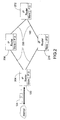
- FIG. 3 is a functional block diagram of a fiber optic ring network including a plurality of nodes for routing IP user traffic over a fiber optic ring network according to a preferred embodiment of the invention.
- a node 300 includes a processor 304.
- Processor 304 is coupled to communicate with a memory 308 for storing a routing table, a memory 312 for storing a forwarding table, and a storage device 316 for storing computer instructions.
- the computer instructions are instructions that defined the functions that are to be performed by node 300 including creating the routing and forwarding tables stored in memories 308 and 312, respectively.
- Processor 304 also is coupled to a pair of transceivers 324 and 328 (interface devices) for transceiving communication signals on a first and a second ring of the fiber optic ring network.
- the first ring is the working path ring and the second ring comprises a protection path ring wherein the amount of reserved capacity is equal to the working path capacity.
- the invention contemplates utilizing both rings for carrying working path traffic. Unlike the traditional approach of reserving equal resources for working path as well as for protection path, the amount of resources reserved for working paths is greater than what is reserved for the protection paths in the described embodiments of the invention.
- Nodes 340, 344 and 348 each include a processor communicatively coupled with a memory for storing a forwarding table and a storage device for storing computer instructions that defined operational logic and responses for the nodes. Additionally, each of the nodes 340, 344 and 348 include a pair of transceivers for transceiving communication signals on the first and second rings. As may be seen, for the purposes of explaining the operation of the invention herein, the nodes 340, 344 and 348 do not include a memory for storing a routing table.
- each of the nodes 300, 340, 344 and 348 include the elements and logic described herein.
- the different nodes may have different functionality.
- nodes 300, 340, 344 and 348 also include a transceiver port for receiving and transmitting IP user traffic from and to the internet and may act as an ingress or central node.
- the nodes can include memory for storing routing tables in an alternate embodiment.
- the additional logic devices and transceivers are not explicitly shown herein for simplicity.
- central node 300 receives IP user traffic from the internet and converts the IP user traffic to a format suitable for the fiber optic ring network of Figure 3 .
- a TDM format is used for conducting traffic through the ring network.
- a central node 300 receives the IP user traffic, converts it to a TDM format, and then decides how to properly route the traffic according to its routing and forwarding tables stored within its memory as will be described in greater specificity below.
- node 300 inserts a label in the header of the TDM traffic in the described embodiment.
- the nodes within the network then utilize a multi-protocol label switching (MPLS) to forward the packet through the network.
- MPLS multi-protocol label switching
- the described embodiment includes using an MPLS scheme in which each node examines a label value in a received packet, determines a corresponding label value that implicitly defines several parameters including the next path and communication link, and then transmits the packet with the corresponding label value.
- inventive nodes include logic within the storage devices that prompt the processing unit to generate an overhead signal.
- the overhead signal is transmitted by at least one node that detects the communication link condition or failure in an adjacent communication link to all other nodes in the fiber optic ring network including the central or ingress node 300.
- Node 300 responsive to receiving the overhead signal responds by assigning labels having label values that cause all subsequent packets whose working path includes going through the failed communication link to be transmitted by way of a protection path to avoid the communication link failure.
- FIG 4 is a functional schematic illustrating the components of a central ingress node according to a preferred embodiment of the invention.
- an ingress node 400 is a node that receives IP traffic that requires routing through the fiber optic ring network.
- the ingress node 400 is responsible for determining the path route for a data packet through the fiber optic ring network.
- Central ingress node 400 includes a processor 402 that is communicatively coupled to a memory 404, a storage device 406 and a peripheral bus interface through a bus 410.
- Peripheral bus interface is communicatively coupled with network interface devices 412A, 412B, 412C, 412D and 412E.
- Each of these network interface devices are connected, for exemplary purposes, to an IP router, an IP node, a first ring of a fiber optic ring network, a second ring of a fiber optic ring network, and a communication control line, respectively.
- Storage device 406 can be formed of any one or of a plurality of devices for storing operational logic, protocol information, programming steps and instructions, and gateway logic to convert signals from one protocol to another.
- portion 406A is for storing instructions for creating forwarding and routing tables.
- portion 406B is for storing operational logic for determining whether user traffic, on a packet by packet basis should be transmitted or forwarded through the fiber optic ring network through a working path or a protection path.
- Portion 406C is for storing programming and process steps for generating an overhead signal to all nodes on the fiber optic ring network to inform them of a detected communication link failure in an adjacent node.
- storage device 406 comprises, in the described embodiment, an electromagnetic disk drive that has read/write capability.
- storage device 406 comprises read only memory (ROM) circuits, compact disk (CD) ROM devices, Read/Write CDs, tape drives, floppy disks (and similar devices), and other known information storage mediums.
- Storage device 406 of node 400 includes computer instructions that define logic for indicating and causing processor 402 to produce a signal on the fiber optic ring network indicating that a failure condition has occurred in an adjacent communication link on the fiber optic ring. There are many different indicators of failed communication links including the mere lack of receipt of expected communication signals.
- the information in storage device 406 causes processor 402 to generate an overhead signal that is used to inform other nodes on the fiber optic ring network of a detected failure.
- the fiber optic ring network is a SONET ring
- processor 402 generates a k1/k2 overhead signal.
- the computer instructions stored within storage device 406 also define logic for determining that traffic conditions on adjacent communication links require alternate routing/forwarding.
- a specified amount of traffic congestion may be defined to require protection path switching.
- the computer instructions are selected to cause processor 402 to select between the working and protection paths according to traffic conditions on a packet by packet basis.
- the computer instructions within storage device 406 also include instructions for creating routing and forwarding tables.
- an IP router includes logic for creating IP packet routing tables based upon network conditions.
- network conditions includes an awareness of the electrical presence of internet nodes and routers.
- the programming instructions within the central ingress node 400 include similar logic defined by its computer instructions. Additionally, however, the computer instructions in the storage device 406 also include programming steps to define the packet routing/forwarding through the fiber optic ring network.
- the computer instructions within storage device 406 define logic for creating an MPLS forwarding table having entries that define path routes by way of the selected labels that are consistent with the defined routes of the routing table. Additionally, however, the labels define path routes for working as well as protection paths through the fiber optic ring network.
- Memory 404 comprises random access memory (RAM) with read/write capability for storing operational information while node 400 is operational and is receiving power.
- memory portions 404A and 404B are for storing the routing and forwarding tables, respectively, created by processor 402 while executing the programming instructions stored in memory portion 406A of storage device 406.
- Memory portion 406C is for storing information relating to network conditions. By way of example, if node 400 either determines on its own or is informed of a network communication link failure, information defining the type of failure and its location are stored in memory portion 406C of memory 406.
- memory 404 includes data used by processor 402 while executing program steps or computer instructions defined in portions 406A, 406B and 406C of storage device 406 as well as in other portions of the storage device.
- Memory 404 also is for, among other things, storing a fiber optic ring failure condition that was determined by node 300 or that was indicated in a received overhead signal. In terms of hardware characteristics of memory 404, different types of memory may be used. By way of example, memory 404 can comprise 32 bit flash program storage, dynamic RAM, static RAM, etc.
- Processor 402 is a standard processing unit formed within similar computerized devices and is capable of controlling operations of the node 400 according to the operational logic defined within storage 406.
- Processors that may be used include customized ASIC devices, off the shelf processors including common commercially available microprocessors and other similar devices.
- Peripheral bus interface 408 is a standard bus interface that allows processor 402 to communicate with and control the communications that occur over a plurality of network interface devices 412 that are coupled to peripheral bus interface 408.
- Network interface devices 412 are transceivers of various types that are coupled to communicate with specific devices. While the described embodiment includes a peripheral bus interface 408, other known devices may be substituted according to system implementation. By way of example, a cross connect switch or a demultiplexer may be used in place of peripheral bus interface 408.
- the network interface devices of Figure 4 may be formed of different known interface systems. For example, they may comprise radio modems, digital signal processors, ASICs, T1/E1 interface devices, etc.
- the type of device utilized as a network interface device 412 is a function of the type of device with which it will be expected to communicate and can include transceivers of all known types.
- processor 402 of node 400 in the described embodiment, is operable, in conjunction with computer instructions in storage device 406, to detect and respond to the a communication link failure or traffic condition (e.g., congestion). Within the 15 milliseconds, processor 402 generates the overhead signal indicating a communication link failure or traffic condition within fifteen milliseconds of the communication link failure or condition being detected (collectively "communication link failure").
- a communication link failure or traffic condition e.g., congestion
- processor 402 Within the 15 milliseconds, processor 402 generates the overhead signal indicating a communication link failure or traffic condition within fifteen milliseconds of the communication link failure or condition being detected (collectively "communication link failure").
- processor 402 is operable, in conjunction with computer instructions in storage device 406, to detect and respond within a 35 millisecond period to a received overhead signal used to indicate a failure condition in a communication link within the fiber optic ring network. Stated differently, the programming instructions within storage device 406 are written to cause processor 402 to initiate protection path routing/forwarding within 35 milliseconds of receiving the overhead signal.
- processor firmware may be used to generate a flag or interrupt to cause the processor to execute a specified routine to initiate protection path forwarding/switching.
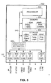
- FIG. 5 is a functional schematic illustrating the components of a fiber optic ring network node according to a preferred embodiment of the invention.
- node 500 is for receiving and forwarding data packets on a fiber optic ring network.
- Node 500 includes a processor 502 that is communicatively coupled to a memory 504, a storage device 506 and a peripheral bus interface through a bus 510.
- Peripheral bus interface is communicatively coupled with network interface devices 512A, 512B, 512C, 512D and 512E. Each of these network interface devices are connected, for exemplary purposes, to an IP router, an IP node, a first ring of a fiber optic ring network, a second ring of a fiber optic ring network, and a communication control line, respectively.
- Storage device 506 can be formed of any one or of a plurality of devices for storing operational logic, protocol information, programming steps and instructions for specified functions.
- portion 506A is for storing instructions for creating and generating error signals regarding communication link failures whenever specified conditions are detected in an adjacent ring.
- portion 506B is for storing operational logic for forwarding received packets, on a packet by packet basis through the fiber optic ring network either through a working path or a protection path.
- Portion 506C is for storing ring topology information for using in determining how to forward a received data packet.
- storage device 506 comprises, in the described embodiment, an electromagnetic disk drive that has read/write capability.
- storage device 506 comprises read only memory (ROM) circuits, compact disk (CD) ROM devices, Read/Write CDs, tape drives, floppy disks (and similar devices), and other known information storage mediums.
- storage device 506 includes computer instructions that define logic for indicating and causing processor 502 to produce a signal on the fiber optic ring network. This signal is for indicating that a failure condition has occurred in an adjacent communication link on the fiber optic ring. There are many different indicators of failed communication links including the mere lack of receipt of expected communication signals.
- the information in storage device 506 causes processor 502 to generate an overhead signal that is used to inform all other nodes on the fiber optic ring network of a detected failure.
- processor 502 generates a k1/k2 overhead signal that is transmitted to all nodes on the fiber optic ring network.
- the computer instructions stored within storage device 506 also define logic for determining that traffic conditions on adjacent communication links require alternate routing/forwarding.
- a specified amount of traffic congestion may be defined to require protection path switching.
- the computer instructions within storage device 506 also include instructions for determining how to forward a received packet.
- the computer instructions within storage device 506B define logic for forwarding data packets according to an MPLS forwarding table stored in memory. As will be described in greater detail below, the computer instructions in portion 506B prompt processor 502 to switch label values for a received packet and to forward the packet according to the newly inserted label value.
- the MPLS labels define path routes for working as well as protection paths through the fiber optic ring network.
- the computer instructions within portion 506A of storage device 506 include defined topology information for the fiber optic ring network.
- defined topology information for the fiber optic ring network.
- information regarding each of the nodes 500 in the ring as well as their node IDs and, in some embodiments, their port IDs.
- the use of the port IDs and node IDs will be described in greater detail below.
- Memory 504 comprises random access memory (RAM) with read/write capability for storing operational information while node 500 is operational and is receiving power.
- Memory portions 504A and 504B are for storing information regarding network conditions and forwarding tables, respectively.
- the forwarding table in memory portion 504B is stored in an MPLS format. Other formats for the forwarding information may also be used for the forwarding to packets through the fiber optic ring network.
- memory 504 can comprise 32 bit flash program storage, dynamic RAM, static RAM, etc.
- Processor 502 is a standard processing unit formed within similar computerized devices and is capable of controlling operations of the node 500 according to the operational logic defined within storage 406. Processors that may be used include customized ASIC devices, off the shelf processors including common commercially available microprocessors and other similar devices.
- processor 502 also is coupled to transmit and receive user traffic on the fiber optic ring network through a plurality of network interface devices 512A through 512E by way of a peripheral bus interface device 508 and a bus 510. While the described embodiment includes a peripheral bus interface 508, other known devices may be substituted according to system implementation. By way of example, a cross connect switch or a demultiplexer may be used in place of peripheral bus interface 508.
- the network interface devices of Figure 5 may be formed of different known interface systems. For example, they may comprise radio modems, digital signal processors, ASICs, T1/E1 interface devices, etc.
- the type of device utilized as a network interface device 512 is a function of the type of device with which it will be expected to communicate and can include transceivers of all known types.
- processor 502 of node 500 in the described embodiment, is operable, in conjunction with computer instructions in storage device 506, to detect and respond to the a communication link failure or traffic condition (e.g., congestion). Within the 15 milliseconds, processor 502 generates the overhead signal indicating a communication link failure or traffic condition within fifteen milliseconds of the communication link failure or condition being detected (collectively "communication link failure").
- a communication link failure or traffic condition e.g., congestion
- processor 502 Within the 15 milliseconds, processor 502 generates the overhead signal indicating a communication link failure or traffic condition within fifteen milliseconds of the communication link failure or condition being detected (collectively "communication link failure").
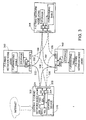
- FIG. 6 is a functional block diagram illustrating packet level forwarding in a fiber optic ring network using multi-packet label switching and forwarding tables according to a preferred embodiment of the invention.
- a fiber optic ring network central node 600 is coupled to receive IP data packets 604 from the internet.
- the fiber optic network ring includes nodes 616, 620 and 624.
- Node 600 includes a memory 608 for storing routing/forwarding information.
- Node 616 includes a memory for storing a forwarding table that has an entry that maps label A2 to label B7.
- Node 620 includes a memory for storing a forwarding table that has an entry that maps label B7 to label C3.
- node 600 In operation, node 600 must change the format of the received IP packet 604 to a TDM format.
- node 600 the preferred embodiment, adds a label to create data packet 612.
- the label implicitly defines a path route for the next communication link.
- node 600 adds label A2 to the data packet 604.
- memory 608 includes a defined path route through the fiber optic ring network. For any packet given the label A2, that packet will be transmitted in a channel or path assigned labels A2, B7 and C3.
- data packet 604 has a destination node within the fiber optic ring network of node 624 prior to be exported to another network such as the internet.
- Node 500 transmits data packet 612 over a channel that corresponds to label A2.
- data packet 612 reaches node 616, its label A2 is replaced with label B7 by node 616 and then is transmitted over the channel that corresponds with label B7 as data packet 618.
- node 620 replaces the label B7 with label C3. The data packet is then transmitted as data packet 622 over the channel that corresponds with label C3.
- each of the nodes 616, 620 and 624 examine additional information within a header of the received data packets to determine whether it is the final destination on the fiber optic ring network for the packet.
- the final node of the fiber optic ring network to receive the data packet is node 624.
- Node 624 upon receiving the data packet, examines a port ID within the header to determine that the specified port ID is a port of node 624.
- the forwarding tables may be used to achieve the same result.
- the memory of node 624 that contains the forwarding tables may be formed to include an entry to correspond to label C3 (the label that is inserted into the packet by node 620) that defines a specified port connected to an external device. Such an entry, therefore, would cause node 624 to realize that the packet is to be output through a specified port to a device that is external to the fiber optic ring network.
- node 624 extracts the destination IP address from the header of the packet, converts the packet back to an IP format (along with other packets if necessary) and routes the packet back on to the internet to reach its destination.
- IP format an IP format (along with other packets if necessary)
- FIG. 7 is a diagram illustrating the elements of a user traffic data packet transmitted by a node on a fiber optic ring network according to a preferred embodiment of the invention.
- an IP packet that is received by a central node 500 is converted to at least one TDM data packet such as data packet 700 shown in Figure 7 .
- the data of the IP data packet is inserted within portion 704.
- Some TDM packets for common fiber optic ring networks are fixed length packets. Accordingly, a plurality of packets may be required if the data portion of the IP packet exceeds the capacity of the fixed length packet. For example, in ATM based fiber optic ring networks, a fixed length packet known as a cell has 48 bytes for carrying user traffic data. Accordingly, an IP packet having more than 48 bytes of data will require a plurality of cells to transport the data from the IP data packet through the fiber optic ring network.
- IP user traffic data is placed within portion 404 of at least one data packet 400
- the IP destination address is placed within portion 408
- the IP source address is placed within portion 412.
- the TDM packet label (MPLS label) is placed in portion 716.
- the label of portion 716 implicitly represents or defines a plurality of different sets of information.
- the label represents the path route that is to transport the data packet for the next communication link.
- the label in the described embodiment also represents a quality of service (QoS) parameter that is associated with the data packet.
- QoS provisioning usually specifies the priority that a given user receives for the user traffic especially in interference situations. Interference situations include those situations where, at a given moment, the demand for channeling resources exceeds throughput capacity.
- the label value inserted into portion 716 also implicitly reflects the bandwidth of the channel being used to transmit the data packet.
- a signal is given a high priority (e.g., a signal being transmitted by a government agency in an emergency situation)
- that high priority can also be implicitly determined by the label assignment.
- a priority signal would receive at least as much priority as a highest QoS rating.
- high priority signals merely receive the highest QoS rating available to expedite their transmission through the fiber optic ring network.
- FIG 8 is a flow chart illustrating a method in a node for forwarding a packet of data on a TDM fiber optic ring network according to a preferred embodiment of the invention.
- a node by way of example, node 616 of Figure 6 receives a data packet similar to packet 612 of Figure 6 (step 502). The node then examines the label of the received packet to determine how to process the packet (step 504).
- the processor of the node communicates with its internal storage device that contains programming instructions. The processor executes the programming instructions to extract the label in the received packet and to store it in memory for futher analysis.
- the node 340 determines whether the packet is to be reconstructed into an IP packet and then output from an output port of the node (step 806). More specifically, the processor (according to stored computer instructions), in the preferred embodiment, examines a specified port identifier that identifies an egress port from the fiber optic ring network to an external device (e.g., to an IP router or IP node external to the fiber optic ring network). If the port identifier is one of the node processing the data packet, then the node examines a forwarding table as a part of processing and forwarding the packet.
- the node rather than examine a port identifier, the node merely examines the received label. Then, from examining the contents of the forwarding table it knows whether to forward the packet with a new label value or whether to output the packet through an egress port. More specifically, if the forwarding table includes an egress port identifier instead of a replacement label, then the node knows to reconstruct the packet into an IP format and to output it through the egress port identified in the forwarding table.
- node determines the corresponding replacement label for the label that was received with the packet (step 808). Thereafter, the processor replaces the received label with the corresponding label value that it determined (step 810). The node then forwards packet according the new label value (step 812).
- FIG. 9 is a flow chart illustrating a method in a node, by way of example nodes 300, 340, 344 or 348 or nodes 400 and 500 of Figures 4 and 5 , respectively, for detecting a communication link failure and for sending a signal to other nodes in the fiber optic ring network to inform them of the communication link failure.
- a node by way of example, node 344, examines the adjacent communication links to verify that they are operating properly (step 902). In the preferred embodiment, the examination of the adjacent communication links occurs on a periodic basis at a frequency that exceeds approximately 60 times per second.
- Node 344 examines the adjacent communication links for layer 1, layer 2 and layer 3 types of failures.
- the term "failure" as used herein includes layer 1 and layer 2 failures as well as layer 3 detected conditions including, by way of example, congestion and is not limited merely to severe failures in which signals are not being successfully transmitted through the communication link.
- the computer instructions that enable a processor within a node to determine that a failure at any of the three OSI layers has occurred are stored within the storage device of the node.
- computer instructions include programming steps to detect error conditions in a variety of ways. More specifically, the computer instructions include programming steps to prompt the node test the communication link, to verify that no fault or error conditions are being indicated through routine error checking approaches, and to monitor transmission delays and whether specified signals are being received on a timely basis. For example, the failure of a successful communication over a link as determined either by uncompleted handshaking between nodes or by the failure of node 348 to receive an expected signal within a specified period indicates a communication link failure in an adjacent communication link.
- node 348 determines whether any detected conditions or failures are of a type that require an ingress node, e.g., node 300 of Figure 3 , to provide path restoration (step 904).
- Path restoration is the switching of communication link path routes from a working path to a protection path for at least some of the affected user data packets. If there is not a problem or condition that requires path restoration, the method illustrated in Figure 9 is complete until its next use.
- our exemplary node 344 If a communication link failure does requires path restoration, i.e., the forwarding of some packets over the protection path, our exemplary node 344 generates an overhead signal on all rings (if more than one) to inform all other nodes on the fiber optic ring network of the communication link failure and its location (step 906).
- k1/k2 overhead bytes are used to reflect a problem in a communication link and its location.
- the overhead signaling that occurs to advise an ingress node of a communication link failure occurs at layer 1 even though the condition may be a layer 2 or a layer 3 condition.
- each node includes logic to perform the method of Figure 9 , each of the two nodes that are adjacent to the communication link failure will generate the overhead signal identifying the failure condition.
- the programming instructions are, in the described embodiment, created to perform the testing and error detection analyses at frequency rate that enables a communication link failure to be detected and responded to within a period of fifteen milliseconds.
- FIG 10 is a flow chart illustrating a method in a fiber optic ring network node for controlling forwarding/routing of the IP traffic through the fiber optic ring according to a preferred embodiment of the invention.
- an ingress node for IP traffic for example, node 300, receives an overhead signal that contains an indication that a communication link in the fiber optic ring network has failed (step 1002).
- "failed" includes OSI level 3 determinations and the location of the failure.
- the signal containing the indication may be received from any node on the fiber optic ring network, by way of example, from nodes 340, 344 or 348.
- node 300 After receiving the signal indicating that a communication link failure or condition has occurred, node 300 identifies the packets that it has received as IP packets and converted to TDM packets that pass through the failed communication link in their defined working paths (step 1004).
- the ingress node updates its forwarding/routing tables to modify the defined working and protection paths for the data packets it generates onto the fiber optic ring network (step 1006).
- the ingress node determines appropriate protection path label values for the affected data packets and sets the labels into the header of the outgoing data packets (step 1008). Finally, the affected data packets are generated onto the fiber optic ring network and are forwarded along the protection paths according to the newly set label values.
- the computer instructions in the ingress node are formed to cause the ingress node to perform the protection path switching within 35 milliseconds of receiving the overhead signal in step 1002. Because the computer instructions in the nodes are formed to generate the overhead signal reflecting an error condition within fifteen milliseconds and the ingress nodes include computer instructions formed to respond to the received overhead signal within thirty five milliseconds, the entire network is created to respond and provide path restoration in a period of fifty milliseconds from a communication link failure.
- the ingress node that determines that a failure condition that has occurred in an adjacent communication link, it will respond and provide path restoration within thirty five milliseconds of detecting the failure condition in addition to generating an overhead signal to all other nodes within fifteen milliseconds.
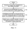
- FIG 11 is a flow chart illustrating a method in a fiber optic ring network node for receiving IP user traffic from an external source and for transmitting it over a fiber optic ring network according to a preferred embodiment of the invention.
- a node by way of example, node 340 of Figure 3 , receives an IP and converts it to a TDM protocol for transmission on the fiber optic ring network (step 1102). If the fiber optic ring network is a SONET ring utilizing an ATM protocol, and, for example, if the actual data of the IP packet exceeds 48 bytes, then a plurality of TDM packets are used to transport the IP packet over the TDM based fiber optic ring network.
- the label value assigned to the packet will reflect a QoS rating or rank.
- node 300 assigns label values reflecting a QoS rank or rating according to either the source or final destination of the IP data packet or to the signal type.
- the node also compares the QoS rating to the rating of all other packets that are to be transmitted. Accordingly, in an interference situation (wherein the instantaneous demand exceeds capacity), the packets having higher QoS ratings will receive labels having label values that gives those packets relative priority through the plurality of paths within a fiber optic ring network.
- the QoS rating is evaluated to ring conditions on the first and second rings as a part of assigning a label having a specified label value (step 1104).
- the node determines whether the data packet is to be transmitted on the first or second ring and what the corresponding path should be based upon its QoS rating and upon the ring conditions in each ring (step 1106). After evaluating the QoS rating, ring conditions and the relative QoS ratings of all of the packets waiting to be transmitted onto the fiber optic ring network, a corresponding label is inserted into the header of the packet and the packet is forwarded on the corresponding path(step 1108).
- FIGS 12A and 12B are tables that illustrate a method for protection path resource allocation according to an embodiment of the invention.
- a traditional resource allocation scheme includes reserving equal amounts of resources for protection paths and amounts of resources for working paths. Stated a differently, a one to one relationship exists between working path and protection path resources.
- each channel identified in the left hand column of the table in Figure 12A for the working paths includes a unique channel assigned to it for protection path forwarding.
- the table of Figure 12B illustrates a four to one resource allocation scheme.
- only one protection path B is reserved for restoration or protection path forwarding for the four paths A, C, E and G.
- each of the reserved protection path channels is equal is throughput capacity to its corresponding working path channel.
- there is no such correlation because there is an "N" to one ratio instead of a one to one ratio between the working and protection path throughput capacities.
- interference situations are resolved through a QoS priority scheme on a packet by packet basis in relation to ring conditions including traffic conditions.
- no channels are reserved for protection path switching. Rather, QoS is used solely to determine traffic priority.
- working path channels are defined on both rings in a two ring system. In a one ring system, working path traffic channels are defined for transmissions in both directions through the fiber optic ring (clockwise and counterclockwise).
- the described embodiments include two ring systems.
- One ring systems capable of conducting user traffic in both directions may readily be substituted for a two ring system.
Abstract
Description
- This application is related to U.S. patent application published as
US 6532088 . - The present invention relates generally to data transmission in fiber optic ring networks, by way of example, the synchronous optical networks, (SONET networks) and Synchronous Digital Hierarchy networks (SDH networks) and more particularly, to the routing of IP data packets through the fiber optic ring networks including SONET and SDH networks.
- The recent explosion of the internet is creating the capability and desire for networks of all types to be integrated and coupled to exchange data signals carrying the varying types of information. In many cases, the same data also will also be transported through a local area network (LAN) prior to being delivered to the internet. Thus, by way of example, a digitized signal can be transported from a source through a LAN and through the internet, to a final destination. Moreover, within the internet portion itself, there may be a need to transport the user data through a backbone data transport infrastructure, by way of example, through a fiber optic ring network.
- Generally speaking, the internet is, in essence, a collection of many large and small computer networks that are coupled together over high speed backbone data links such as T-1, T-3, OC-1 and OC-3. Stated differently, the internet is a network of networks. As a result of the creation of the internet, worldwide access may be achieved. People and their equipment may now communicate from most any civilized point to another in a fast and relatively inexpensive medium.
- While it is popular to think of the internet as one network of networks, there are other such internets that are in existence and that are under development. For example, the network now commonly known as the internet was originally a network of institutional networks including university networks. As a result of the commercialization of the internet and the resultant reduction in quality of service, new generation internet type networks are under development to better achieve the purposes of the original "internet". Moreover, new international standards and protocols are being approved to create additional and enhanced internets. For the sake of simplicity, however, each of the worldwide internet networks will be referred to collectively as the internet.
- Regarding its physical aspects, the internet is a packet switched network that is currently based upon a group of protocols known as transmission control protocol/internet protocol (TCP/IP). TCP is a connection-oriented protocol that first establishes a connection between two computer systems that are to exchange data. TCP then breaks a given digital information signal into packets having a defined format. The packets are then attached to headers that are for containing control and address information.
- For example, in addition to a destination address, a TCP packet typically contains a sequence number that is to be used by the destination in reconstructing a signal that is similar to the original digital information that was broken into packets at the originating end. TCP packets also typically include port IDs, checksum values and other types of control information as is known by those skilled in the art.
- In order to make communication devices created by companies throughout the world compatible with each other to create local area networks and worldwide networks such as the internet, protocols and standards are often defined. These protocols and standards are used to guide the design of the communication devices, and more specifically, to guide the design of the operating logic and software within the devices. While communication devices that are designed in view of these standards do not always follow the suggested models exactly, they are usually compatible with the protocol-defined interfaces (physical and logical). In order to appreciate the construction and operation of many devices, it is important to generally understand the concepts of some of the significant protocol standards and models.
- One important model that currently guides development efforts is the International Standards Organization (ISO) Open Systems Interconnection (OSI) model. ISO/OSI provides a network framework or model that allows equipment from different vendors to communicate with each other. The OSI model organizes the communication process into seven different categories or layers and places these layers in a sequence based on their relation to the user, as is well known in the art.
- With respect to the forgoing discussion regarding the seven OSI layers, IP is a layer three protocol. In contrast, many of the backbone data transport infrastructures utilize a different layer protocol than an internet router.
- Many of the common backbone data transport systems utilized include time division multiplexed (TDM) double ring transmission systems. Double ring TDM systems are generally known, especially for fiber-optic communication networks. In order to maintain transmission in the event of a fault on one of the channels or communication links, it is typically common to find ring transmission systems in which transmissions occur in two directions, Specifically, transmissions occur in one direction through all of the nodes in the ring in a working path and through an opposite direction in a protection path. The protection path is, traditionally, a redundant path for transmitting signals in a failure condition. Examples of fiber optic TDM systems include the SONET and SDH double ring fiber optic communication systems used in North America and Europe, respectively.
- In ordinary conditions, either the user traffic (data) in the redundant path in these double ring systems is not routed through the protection path or, alternatively, it is routed but is not processed by a destination. At the same time, its communication channels are reserved as an alternate path during failure conditions. The redundant path is typically used to route the data signals in an opposite direction from the working path so that data that is to be routed to a destination node located, "downstream" from the failure condition may still be delivered to the destination node.
- One problem with this approach, however, is that the capacity of the redundant ring must be reserved as a redundant path. Transmission efficiency and throughput capacity must be sacrificed to provide data protection. Additionally, error conditions that prompt a node to switch to the protection path often are related to hardware (layer 1) problems in which communications are not being successfully transmitted in a communication link. Switching does not occur for those conditions in which switching may be desirable even if there is not a hardware related error. For example, switching might be desirable to alleviate user traffic congestion.
- Additionally, several challenges exist in implementing dual ring topologies. For example, it is necessary for the switching from the working path to the protection path to occur quickly in the event of a fault so that a minimal amount of information is lost. Typically, switching occurs at the
layer 1 level to minimize the down time. As a result, however, little error protection is provided at the hardware level for failures. Additionally,layer 1 switching results in the switching of entire data transport pipelines. By way of example, a typical pipeline that is switched as a result of alayer 1 switching decision and event is either a 155 mega bits per second (Mbps), 622 Mbps or 2.4 giga bits per second (Gbps) pipeline. - To accomplish fast switching,
layer 1 overhead signaling messages are generated and transmitted back to the ingress node (among other nodes) identifying the fault condition so that the protection switching may occur quickly. More specifically,layer 1 overhead signaling messages are transmitted by the nodes detecting the error (typically the two nodes on either traffic side of the detected problem) on a communication link so that the ingress node may effectuate the change on a quick basis. Typically, the ingress node includes dedicated circuitry for reading, interpreting and quickly responding to the overhead signaling message to effectuate a change. As is implied by the foregoing discussion, the overhead signaling is set upon the occurrence of a significant hardware failure in a communication link. - Historically, delays that are encountered in the internet have been acceptable, though not well liked, in the context of computer to computer communications. As other types of data are transported over the internet, by way of example, either voice or video, there will be a need for transporting data in large quantities in a quick manner. Due to this reason, failure recovery should be fast. There is, therefore, an increasing need for integrating internet communication networks with fiber optic ring networks utilizing a TDM protocol for transporting data because of the speed and throughput capacity of fiber optic ring networks. Accordingly, there is a need for a fiber optic ring network node that is capable of reliably and quickly transporting user traffic to and from the internet. European Patent Application
0 721 275 discloses a node of an optical network. An OAM (operations, administration and maintenance) controller produces an electrical OAM signal to control an optical cross-connect switch onOSI level 1. - European Patent Application
0 924 952 discloses multi-layered architectures for communication networks comprising a first layer forming a transport network and a second layer forming a service network. The transport network provides bandwidth management, high capacity and physical layer survivability, and the service network provides switching and routing of the traffic, service layer survivability and other user oriented services. - To overcome the shortcomings of the prior systems and their operations, the present invention contemplates a fiber optic ring network node that includes a forwarding table that allows the node the capability of routing a data packet through a working path or through a protection path in a fiber optic ring network on a packet by packet basis. The node further includes circuitry that prompts the node to generate an overhead signal on the fiber optic ring network to all other nodes connected to the ring to advise them of a failure condition in a communication link that is adjacent to the node. The types of failure conditions that result in the overhead signal being generated by the node included
typical OSI layer 1 faults as well aslayer 2 faults andlayer 3 conditions.Layer 3 conditions include traffic congestion and other similar conditions. Because each node on the fiber optic ring network includes the circuitry for generating the overhead signal whenever a failure condition occurs in a communication link, two overhead signals will typically be generated, one by each node adjacent to the failure condition location. - Responsive to the receipt of at least one overhead signal identifying a communication link failure, a node serving as an ingress node for IP user traffic performs packet level path restoration on a very fast basis. Subsequent data packets whose ordinary working path routes are affected by the communication link failure may be routed by its ingress node on a protection path route to reach its destination node.
- The inventive system is designed to provide very fast packet level path restoration. Because the overhead signal that advises all of the nodes on the fiber optic ring network is generated at the
layer 2 level of the OSI model, the signal is generated very quickly after the communication link failure occurs. In a preferred embodiment, the computer circuitry is optimized to generate the overhead signal within fifteen milliseconds of the failure condition occurring. Similarly, the ingress nodes are formed to perform path restoration within thirty five milliseconds of receiving the overhead signal. In total, therefore, path restoration occurs within fifty milliseconds of a failure condition occurring. - The types of failures that prompt the node to generate the overhead signal advising of a failure include not only the
layer 1 andlayer 2 failures, but also thelayer 3 types of network conditions. Accordingly, even a condition such as congestion in a communication link may prompt nodes on the network to switch from the first to the second ring. As such, evenlayer 3 conditions that have, in the past, gone undetected for as long as a minute or more, are detected and responded to by the inventive systems disclosed herein within fifty milliseconds. - Because the invention contemplates packet level path restoration depending on factors such as destination and path conditions, there no longer exists a need to reserve large amounts of bandwidth on the second fiber optic ring network to provide protection path capacity. Additionally, in one embodiment of the invention, no reservations are made for protection path switching. Rather, each signal is assigned a quality of service (QoS) priority that is used to resolve interference conditions wherein signals are transmitted in order of priority. As a result, large gains in fiber optic ring network throughput capacity may be realized.
- A better understanding of the present invention can be obtained when the following detailed description of the preferred embodiment is considered with the following drawings, in which:
- Figure 1
- is a functional block diagram of a schematic of a network for transporting IP user traffic over a fiber optic ring;
- Figure 2
- is a schematic diagram of a plurality of IP routers connected in a fiber optic ring for transporting IP user traffic over a fiber optic ring network;
- Figure 3
- is a functional block diagram of a fiber optic ring network including a plurality of nodes for routing IP user traffic over a fiber optic ring network according to a preferred embodiment of the invention;
- Figure 4
- is a functional schematic illustrating the components of a central ingress node according to a preferred embodiment of the invention;
- Figure 5
- is a functional schematic illustrating the components of a fiber optic ring network node according to a preferred embodiment of the invention;
- Figure 6
- is a functional block diagram illustrating packet level forwarding in a fiber optic ring network using multi-packet label switching and forwarding tables according to a preferred embodiment of the invention;
- Figure 7
- is a diagram illustrating the elements of a user traffic data packet transmitted by a node on a fiber optic ring network according to a preferred embodiment of the invention;
- Figure 8
- is a flow chart illustrating a method in a node for forwarding a packet of data on a TDM fiber optic ring network according to a preferred embodiment of the invention;
- Figure 9
- is a flow chart illustrating a method in a node for detecting a communication link failure and for sending a signal to other nodes in the fiber optic ring network to inform them of the communication link failure;
- Figure 10
- is a flow chart illustrating a method in a fiber optic ring network node for controlling forwarding/routing of the IP traffic through the fiber optic ring according to a preferred embodiment of the invention;
- Figure 11
- is a flow chart illustrating a method in a fiber optic ring network node for receiving IP user traffic from an external source and for transmitting it over a fiber optic ring network according to a preferred embodiment of the invention; and
- Figures 12A and 12B
- are tables that illustrate a method for protection path resource allocation according to an embodiment of the invention.
- Modern networks are being designed to transport user traffic containing varying types of information including voice, image, text, control signals and numerical data. The user traffic is routed through access multiplexers, gateways (interface devices for systems communicating using differing formats), add drop multiplexers (ADMs), fiber optic cross connects, ATM switches and internet protocol (IP) routers. Multiple layers of routing, multiple logical layers of path establishment, and different technologies guide the routing and paths used for transporting the user traffic.
- As mentioned before, the internet is a plurality of networks that are coupled by high capacity data transport mediums. One very important data transport medium is the fiber optic ring network such as SONET or SDH networks (collectively, "fiber optic ring networks). Fiber optic ring networks typically utilize a protocol that includes data packets having a fixed or defined length. For example, a SONET network "cell" is a data packet that allocates 48 bytes for data and 5 bytes for a header.
- The fiber optic ring network is, today, a dual ring fiber optic network that transports optical signals in a working path and, at least occasionally, in a protection path using time division multiplexing. Because fiber optic ring networks will increasingly be used to transport IP user data as the importance of the internet continues to grow, the fiber optic ring networks and IP networks must be made to coexist in a compatible and acceptable manner. By some estimates, IP traffic will be the most common type of traffic transported over fiber optic ring networks in the next century.
- Accordingly, there is an increasing need for transporting IP over fiber optic ring networks. The inventors herein have observed that combining IP and TDM to meet this need, however, requires
level 3 type functionality to be performed in addition tolevel 1 andlevel 2 functionality on the fiber optic ring networks. This combination is necessary in order to have a system that is able to fully interact with IP Routers and that can dynamically make routing decisions on a fiber optic ring network as communication link problems are detected. -
Figure 1 is a functional block diagram of a schematic of a network for transporting IP user traffic over a fiber optic ring. Referring now toFigure 1 ,central IP router 100 is connected to deliver and receive IP user traffic to and fromADM 104.ADM 104 is coupled to transmit and receive user traffic overfiber optic ring 108 in a TDM format.Central IP router 100 is coupled toIP routers control lines central IP router 100 was the ingress node. Generally, each of therouters IP router 100 is a "central" IP router for all user traffic for whichIP router 100 was the ingress point for the fiber optic ring network. - As may be seen,
central IP router 100 also is connected to the internet to receive internet user traffic as well asinternet parameter data 124 as shown inFigure 1 . Internet parameter data includes information regarding networks and computer systems that are coupled to the internet as well as path information (e.g., communication link failures).Central IP router 100 uses the internet parameter information to determine IP packet routing whenever it receives a packet of data that is to be transmitted to a specified location. - In operation,
central IP router 100 receives user traffic in IP packet form from, by way of example, the internet and determines where the packet should be routed. For those packets that it determines should be routed through the fiber optic ring network,central IP router 100 produces the user traffic to the fiber optic ring ADM without any knowledge of the fiber optic ring architecture or its available paths.Central IP router 100 merely specifies the destination IP router address and allowsADM 104 to route the IP packets to the ADM that is coupled to the specified IP router that is specified in the IP path routes. Stated differently,central IP router 100 treats the ADM and the fiber optic ring merely as a transport layer. - One less desirable effect of this configuration is that the IP router does not receive or evaluate information regarding topology (including
layer 1 orlayer 2 failure information) or restoration capability, for the fiber optic ring. Stated differently, thelayer 3 routing functionality ofcentral IP router 100 does not include any analysis oflayer 1 andlayer 2 operations in the fiber optic ring. Thus, thelayer 3 functionality ofcentral IP router 100 only detects alayer 1 failure condition in the fiber optic ring whenever user traffic fails to reach a destination. - One advantage of the configuration of
Figure 1 is that it provides for fast switching times in the fiber optic ring in the event of alayer 1 orlayer 2 failure within the ring. A disadvantage is cost because it requires a full IP router and an ADM at each node of the fiber optic ring in addition to a separate star or mesh network coupling each IP router in the network to thecentral IP router 100. That the fiber optic ring performs switching within its network in response to a failure transparently with respect to the IP router suggests that throughput redundancy is required. In other words, the capacity of the working paths in a fiber optic ring network must be duplicated in a protection path to have a system that transparently switches user traffic paths whenever a communication link failure occurs. It is common, by way of example, to have channels of at least 155 Mbps capacity to be fully reserved on the protection path for corresponding channels on the working path. Thus, while the solution ofFIG. 1 is advantageous in that protection switching occurs quickly at thelayer 1 andlayer 2 levels, it is not an economic solution in terms of transport efficiency. -
Figure 2 is a schematic diagram of a plurality of IP routers connected in a fiber optic ring for transporting IP user traffic over a fiber optic ring network. Referring now toFigure 2 , acentral IP router 204 is coupled toIP routers fiber optic ring 220.IP router 204 also is coupled to receiver user traffic andinternet parameter data 124 from an external source (e.g., the internet). - In operation,
central IP router 204 receives user traffic and routes it through the fiber ring network of IP routers according to IP addresses specified in the headers of the IP packets according to TCP/IP formats and protocols. One advantage of the network ofFigure 2 is that it is less expensive than the network ofFigure 1 because it does not require the ADMs to route the IP user traffic yet it is capable of routing IP user traffic over a fiber optic ring network. A disadvantage observed by the inventors of this application, however, is that the IP routers 204 - 216 ofFigure 2 operate atlayer 3 of the OSI model. Accordingly, in the event of alayer 1 orlayer 2 type of communication link failure, it may take tens of seconds or even minutes to detect the failure by thelayer 3 functionality ofIP router 204. Typically, communication link failures are detected atlayer 3 when the IP router transmitting an IP packet of user traffic does not receive an expected signal. It would be advantageous to have a system in which functionality oflayers 1 through 3 are provided in a system capable of responding to failures and conditions detected at any layer within fifty milliseconds. -
Figure 3 is a functional block diagram of a fiber optic ring network including a plurality of nodes for routing IP user traffic over a fiber optic ring network according to a preferred embodiment of the invention. Referring now toFigure 3 , anode 300 includes aprocessor 304.Processor 304 is coupled to communicate with a memory 308 for storing a routing table, a memory 312 for storing a forwarding table, and astorage device 316 for storing computer instructions. The computer instructions are instructions that defined the functions that are to be performed bynode 300 including creating the routing and forwarding tables stored in memories 308 and 312, respectively. -
Processor 304 also is coupled to a pair oftransceivers 324 and 328 (interface devices) for transceiving communication signals on a first and a second ring of the fiber optic ring network. Traditionally, the first ring is the working path ring and the second ring comprises a protection path ring wherein the amount of reserved capacity is equal to the working path capacity. As will be described in greater detail, however, the invention contemplates utilizing both rings for carrying working path traffic. Unlike the traditional approach of reserving equal resources for working path as well as for protection path, the amount of resources reserved for working paths is greater than what is reserved for the protection paths in the described embodiments of the invention. -
Nodes nodes nodes - In the described embodiments of the invention, each of the
nodes nodes - In operation, the invention herein includes many different inventive processes and methods. In general, however,
central node 300 receives IP user traffic from the internet and converts the IP user traffic to a format suitable for the fiber optic ring network ofFigure 3 . For example, in the described embodiment, a TDM format is used for conducting traffic through the ring network. - More specifically, a
central node 300 receives the IP user traffic, converts it to a TDM format, and then decides how to properly route the traffic according to its routing and forwarding tables stored within its memory as will be described in greater specificity below. To transmit the TDM user traffic,node 300 inserts a label in the header of the TDM traffic in the described embodiment. The nodes within the network then utilize a multi-protocol label switching (MPLS) to forward the packet through the network. - While different types of packets and forwarding schemes may be used, the described embodiment includes using an MPLS scheme in which each node examines a label value in a received packet, determines a corresponding label value that implicitly defines several parameters including the next path and communication link, and then transmits the packet with the corresponding label value.
- Additionally, the inventive nodes include logic within the storage devices that prompt the processing unit to generate an overhead signal. The overhead signal is transmitted by at least one node that detects the communication link condition or failure in an adjacent communication link to all other nodes in the fiber optic ring network including the central or
ingress node 300.Node 300, responsive to receiving the overhead signal responds by assigning labels having label values that cause all subsequent packets whose working path includes going through the failed communication link to be transmitted by way of a protection path to avoid the communication link failure. - If, by way of example, a link failure occurs in the portion of the working paths of
ring 332 in betweennodes node 300 tonode node 348, are transmitted through a protection path alongring 336 directly fromnode 300 tonode 348. This examples assumes that the working path traffic flows fromnode 300 tonode 348 throughnodes -
Figure 4 is a functional schematic illustrating the components of a central ingress node according to a preferred embodiment of the invention. Referring now toFigure 4 , aningress node 400, for the purposes herein, is a node that receives IP traffic that requires routing through the fiber optic ring network. In the preferred embodiment of the invention, theingress node 400 is responsible for determining the path route for a data packet through the fiber optic ring network. -
Central ingress node 400 includes aprocessor 402 that is communicatively coupled to amemory 404, astorage device 406 and a peripheral bus interface through abus 410. Peripheral bus interface, in turn, is communicatively coupled withnetwork interface devices -
Storage device 406 can be formed of any one or of a plurality of devices for storing operational logic, protocol information, programming steps and instructions, and gateway logic to convert signals from one protocol to another. By way of example,portion 406A is for storing instructions for creating forwarding and routing tables.Portion 406B is for storing operational logic for determining whether user traffic, on a packet by packet basis should be transmitted or forwarded through the fiber optic ring network through a working path or a protection path.Portion 406C is for storing programming and process steps for generating an overhead signal to all nodes on the fiber optic ring network to inform them of a detected communication link failure in an adjacent node. - In terms of hardware,
storage device 406 comprises, in the described embodiment, an electromagnetic disk drive that has read/write capability. In additional embodiments,storage device 406 comprises read only memory (ROM) circuits, compact disk (CD) ROM devices, Read/Write CDs, tape drives, floppy disks (and similar devices), and other known information storage mediums. -
Storage device 406 ofnode 400 includes computer instructions that define logic for indicating and causingprocessor 402 to produce a signal on the fiber optic ring network indicating that a failure condition has occurred in an adjacent communication link on the fiber optic ring. There are many different indicators of failed communication links including the mere lack of receipt of expected communication signals. In the described embodiment, the information instorage device 406 causesprocessor 402 to generate an overhead signal that is used to inform other nodes on the fiber optic ring network of a detected failure. By way of example, if the fiber optic ring network is a SONET ring,processor 402 generates a k1/k2 overhead signal. - Those skilled in the art readily can appreciate the specific conditions that could cause a node to determine a communication link failure has occurred in an adjacent communication link. The computer instructions stored within
storage device 406 also define logic for determining that traffic conditions on adjacent communication links require alternate routing/forwarding. By way of example, a specified amount of traffic congestion may be defined to require protection path switching. In the preferred embodiment of the invention, the computer instructions are selected to causeprocessor 402 to select between the working and protection paths according to traffic conditions on a packet by packet basis. - The computer instructions within
storage device 406 also include instructions for creating routing and forwarding tables. To illustrate, as is known by those skilled in the art, an IP router includes logic for creating IP packet routing tables based upon network conditions. The phrase "network conditions" includes an awareness of the electrical presence of internet nodes and routers. The programming instructions within thecentral ingress node 400 include similar logic defined by its computer instructions. Additionally, however, the computer instructions in thestorage device 406 also include programming steps to define the packet routing/forwarding through the fiber optic ring network. - In addition, the computer instructions within
storage device 406 define logic for creating an MPLS forwarding table having entries that define path routes by way of the selected labels that are consistent with the defined routes of the routing table. Additionally, however, the labels define path routes for working as well as protection paths through the fiber optic ring network. -
Memory 404 comprises random access memory (RAM) with read/write capability for storing operational information whilenode 400 is operational and is receiving power. By way of example,memory portions processor 402 while executing the programming instructions stored inmemory portion 406A ofstorage device 406.Memory portion 406C is for storing information relating to network conditions. By way of example, ifnode 400 either determines on its own or is informed of a network communication link failure, information defining the type of failure and its location are stored inmemory portion 406C ofmemory 406. - Additionally, information stored within
storage device 406C defining the fiber optic network ring node such as the nodes that are electrically present, and the communication paths are stored inmemory portion 404C for use byprocessor 402. Additionally,memory 404 includes data used byprocessor 402 while executing program steps or computer instructions defined inportions storage device 406 as well as in other portions of the storage device.Memory 404 also is for, among other things, storing a fiber optic ring failure condition that was determined bynode 300 or that was indicated in a received overhead signal. In terms of hardware characteristics ofmemory 404, different types of memory may be used. By way of example,memory 404 can comprise 32 bit flash program storage, dynamic RAM, static RAM, etc.Processor 402 is a standard processing unit formed within similar computerized devices and is capable of controlling operations of thenode 400 according to the operational logic defined withinstorage 406. Processors that may be used include customized ASIC devices, off the shelf processors including common commercially available microprocessors and other similar devices. -
Peripheral bus interface 408 is a standard bus interface that allowsprocessor 402 to communicate with and control the communications that occur over a plurality ofnetwork interface devices 412 that are coupled toperipheral bus interface 408.Network interface devices 412 are transceivers of various types that are coupled to communicate with specific devices. While the described embodiment includes aperipheral bus interface 408, other known devices may be substituted according to system implementation. By way of example, a cross connect switch or a demultiplexer may be used in place ofperipheral bus interface 408. - The network interface devices of
Figure 4 may be formed of different known interface systems. For example, they may comprise radio modems, digital signal processors, ASICs, T1/E1 interface devices, etc. The type of device utilized as anetwork interface device 412 is a function of the type of device with which it will be expected to communicate and can include transceivers of all known types. - In operation,
processor 402 ofnode 400, in the described embodiment, is operable, in conjunction with computer instructions instorage device 406, to detect and respond to the a communication link failure or traffic condition (e.g., congestion). Within the 15 milliseconds,processor 402 generates the overhead signal indicating a communication link failure or traffic condition within fifteen milliseconds of the communication link failure or condition being detected (collectively "communication link failure"). - Similarly, in the described embodiment,
processor 402 is operable, in conjunction with computer instructions instorage device 406, to detect and respond within a 35 millisecond period to a received overhead signal used to indicate a failure condition in a communication link within the fiber optic ring network. Stated differently, the programming instructions withinstorage device 406 are written to causeprocessor 402 to initiate protection path routing/forwarding within 35 milliseconds of receiving the overhead signal. - Any known scheme for causing a processing unit to respond promptly including an interrupt scheme may be used. By way of example, processor firmware may be used to generate a flag or interrupt to cause the processor to execute a specified routine to initiate protection path forwarding/switching.
-
Figure 5 is a functional schematic illustrating the components of a fiber optic ring network node according to a preferred embodiment of the invention. In general,node 500 is for receiving and forwarding data packets on a fiber optic ring network.Node 500 includes aprocessor 502 that is communicatively coupled to amemory 504, astorage device 506 and a peripheral bus interface through abus 510. Peripheral bus interface, in turn, is communicatively coupled withnetwork interface devices -
Storage device 506 can be formed of any one or of a plurality of devices for storing operational logic, protocol information, programming steps and instructions for specified functions. By way of example,portion 506A is for storing instructions for creating and generating error signals regarding communication link failures whenever specified conditions are detected in an adjacent ring.Portion 506B is for storing operational logic for forwarding received packets, on a packet by packet basis through the fiber optic ring network either through a working path or a protection path.Portion 506C is for storing ring topology information for using in determining how to forward a received data packet. - In terms of hardware,
storage device 506 comprises, in the described embodiment, an electromagnetic disk drive that has read/write capability. In additional embodiments,storage device 506 comprises read only memory (ROM) circuits, compact disk (CD) ROM devices, Read/Write CDs, tape drives, floppy disks (and similar devices), and other known information storage mediums. - With respect to the programming instructions stored in
portion 506A ofstorage device 506 ofnode 500,storage device 506 includes computer instructions that define logic for indicating and causingprocessor 502 to produce a signal on the fiber optic ring network. This signal is for indicating that a failure condition has occurred in an adjacent communication link on the fiber optic ring. There are many different indicators of failed communication links including the mere lack of receipt of expected communication signals. - In the described embodiment, the information in
storage device 506 causesprocessor 502 to generate an overhead signal that is used to inform all other nodes on the fiber optic ring network of a detected failure. By way of example, if the fiber optic ring network is a SONET ring,processor 502 generates a k1/k2 overhead signal that is transmitted to all nodes on the fiber optic ring network. - Those skilled in the art readily can appreciate the specific conditions that could cause a node to determine a communication link failure has occurred in an adjacent communication link. The computer instructions stored within
storage device 506 also define logic for determining that traffic conditions on adjacent communication links require alternate routing/forwarding. By way of example, a specified amount of traffic congestion may be defined to require protection path switching. - The computer instructions within
storage device 506 also include instructions for determining how to forward a received packet. The computer instructions withinstorage device 506B define logic for forwarding data packets according to an MPLS forwarding table stored in memory. As will be described in greater detail below, the computer instructions inportion 506Bprompt processor 502 to switch label values for a received packet and to forward the packet according to the newly inserted label value. The MPLS labels define path routes for working as well as protection paths through the fiber optic ring network. - The computer instructions within
portion 506A ofstorage device 506 include defined topology information for the fiber optic ring network. By way of example, information regarding each of thenodes 500 in the ring as well as their node IDs and, in some embodiments, their port IDs. The use of the port IDs and node IDs will be described in greater detail below. -
Memory 504 comprises random access memory (RAM) with read/write capability for storing operational information whilenode 500 is operational and is receiving power.Memory portions node 500 either determines on its own or is informed of a network communication link failure, information defining the type of failure and its location are stored inmemory portion 506A ofmemory 506. The forwarding table inmemory portion 504B is stored in an MPLS format. Other formats for the forwarding information may also be used for the forwarding to packets through the fiber optic ring network. - In terms of hardware characteristics of
memory 504, different types of memory may be used. By way of example,memory 504 can comprise 32 bit flash program storage, dynamic RAM, static RAM, etc.Processor 502 is a standard processing unit formed within similar computerized devices and is capable of controlling operations of thenode 500 according to the operational logic defined withinstorage 406. Processors that may be used include customized ASIC devices, off the shelf processors including common commercially available microprocessors and other similar devices. - Continuing to refer to
Figure 5 ,processor 502 also is coupled to transmit and receive user traffic on the fiber optic ring network through a plurality ofnetwork interface devices 512A through 512E by way of a peripheralbus interface device 508 and abus 510. While the described embodiment includes aperipheral bus interface 508, other known devices may be substituted according to system implementation. By way of example, a cross connect switch or a demultiplexer may be used in place ofperipheral bus interface 508. - The network interface devices of
Figure 5 may be formed of different known interface systems. For example, they may comprise radio modems, digital signal processors, ASICs, T1/E1 interface devices, etc. The type of device utilized as anetwork interface device 512 is a function of the type of device with which it will be expected to communicate and can include transceivers of all known types. - In operation,
processor 502 ofnode 500, in the described embodiment, is operable, in conjunction with computer instructions instorage device 506, to detect and respond to the a communication link failure or traffic condition (e.g., congestion). Within the 15 milliseconds,processor 502 generates the overhead signal indicating a communication link failure or traffic condition within fifteen milliseconds of the communication link failure or condition being detected (collectively "communication link failure"). -
Figure 6 is a functional block diagram illustrating packet level forwarding in a fiber optic ring network using multi-packet label switching and forwarding tables according to a preferred embodiment of the invention. A fiber optic ring networkcentral node 600 is coupled to receiveIP data packets 604 from the internet. In addition tonode 600, the fiber optic network ring includesnodes Node 600 includes amemory 608 for storing routing/forwarding information.Node 616 includes a memory for storing a forwarding table that has an entry that maps label A2 to label B7.Node 620 includes a memory for storing a forwarding table that has an entry that maps label B7 to label C3. - In operation,
node 600 must change the format of the receivedIP packet 604 to a TDM format. In the process of forming a TDM packet,node 600, the preferred embodiment, adds a label to createdata packet 612. The label implicitly defines a path route for the next communication link. For the example herein,node 600 adds label A2 to thedata packet 604. As may be seen,memory 608 includes a defined path route through the fiber optic ring network. For any packet given the label A2, that packet will be transmitted in a channel or path assigned labels A2, B7 and C3. For the example herein,data packet 604 has a destination node within the fiber optic ring network ofnode 624 prior to be exported to another network such as the internet. -
Node 500 transmitsdata packet 612 over a channel that corresponds to label A2. Whendata packet 612 reachesnode 616, its label A2 is replaced with label B7 bynode 616 and then is transmitted over the channel that corresponds with label B7 asdata packet 618. Similarly,node 620 replaces the label B7 with label C3. The data packet is then transmitted asdata packet 622 over the channel that corresponds with label C3. - In the example herein, each of the
nodes Figure 6 , the final node of the fiber optic ring network to receive the data packet isnode 624.Node 624, upon receiving the data packet, examines a port ID within the header to determine that the specified port ID is a port ofnode 624. - Other designs may also be used to accomplish the same result. Rather than having the nodes examine port IDs in the header of the received data packets, the forwarding tables may be used to achieve the same result. By way of example, the memory of
node 624 that contains the forwarding tables may be formed to include an entry to correspond to label C3 (the label that is inserted into the packet by node 620) that defines a specified port connected to an external device. Such an entry, therefore, would causenode 624 to realize that the packet is to be output through a specified port to a device that is external to the fiber optic ring network. - In either embodiment,
node 624 extracts the destination IP address from the header of the packet, converts the packet back to an IP format (along with other packets if necessary) and routes the packet back on to the internet to reach its destination. Those skilled in the art readily know how to convert back and forth between TDM and IP formats. -
Figure 7 is a diagram illustrating the elements of a user traffic data packet transmitted by a node on a fiber optic ring network according to a preferred embodiment of the invention. Referring now toFigure 7 , an IP packet that is received by acentral node 500 is converted to at least one TDM data packet such asdata packet 700 shown inFigure 7 . The data of the IP data packet is inserted withinportion 704. Some TDM packets for common fiber optic ring networks are fixed length packets. Accordingly, a plurality of packets may be required if the data portion of the IP packet exceeds the capacity of the fixed length packet. For example, in ATM based fiber optic ring networks, a fixed length packet known as a cell has 48 bytes for carrying user traffic data. Accordingly, an IP packet having more than 48 bytes of data will require a plurality of cells to transport the data from the IP data packet through the fiber optic ring network. - While IP user traffic data is placed within
portion 404 of at least onedata packet 400, the IP destination address is placed withinportion 408 and the IP source address is placed withinportion 412. As is also shown inFigure 7 , the TDM packet label (MPLS label) is placed inportion 716. - Because the preferred embodiment of the invention utilizes an MPLS scheme for transporting data packets, the label of
portion 716 implicitly represents or defines a plurality of different sets of information. By way of example, the label represents the path route that is to transport the data packet for the next communication link. In addition to the path route, the label in the described embodiment also represents a quality of service (QoS) parameter that is associated with the data packet. As is understood by those skilled in the art, QoS provisioning usually specifies the priority that a given user receives for the user traffic especially in interference situations. Interference situations include those situations where, at a given moment, the demand for channeling resources exceeds throughput capacity. - Different throughput rates (or levels of priority in a QoS system) typically have different cost structures. Accordingly, in the case of traffic congestion, QoS priority schemes are used to determine what signals are transmitted or are transmitted first. Finally, in the preferred embodiment, a priority indication for reasons other than QoS are specified. For example, communications by public officials regarding important public events may be given a high priority.
- Finally, the label value inserted into
portion 716 also implicitly reflects the bandwidth of the channel being used to transmit the data packet. As may be seen by examiningFigure 7 , if a signal is given a high priority (e.g., a signal being transmitted by a government agency in an emergency situation), that high priority can also be implicitly determined by the label assignment. Typically, it may be difficult to distinguish between a label for a signal being given high priority and a label for a signal having a high QoS rating. As a general observation, however, a priority signal would receive at least as much priority as a highest QoS rating. Accordingly, it is only in the situation wherein a signal receives an optimal label assignment that some ambiguity may exist as to whether it is a priority signal or a signal with a high QoS. In one embodiment, high priority signals merely receive the highest QoS rating available to expedite their transmission through the fiber optic ring network. -
Figure 8 is a flow chart illustrating a method in a node for forwarding a packet of data on a TDM fiber optic ring network according to a preferred embodiment of the invention. Referring now toFigure 8 , a node, by way of example,node 616 ofFigure 6 receives a data packet similar topacket 612 ofFigure 6 (step 502). The node then examines the label of the received packet to determine how to process the packet (step 504). By way of example, the processor of the node communicates with its internal storage device that contains programming instructions. The processor executes the programming instructions to extract the label in the received packet and to store it in memory for futher analysis. Thereafter, thenode 340 determines whether the packet is to be reconstructed into an IP packet and then output from an output port of the node (step 806). More specifically, the processor (according to stored computer instructions), in the preferred embodiment, examines a specified port identifier that identifies an egress port from the fiber optic ring network to an external device (e.g., to an IP router or IP node external to the fiber optic ring network). If the port identifier is one of the node processing the data packet, then the node examines a forwarding table as a part of processing and forwarding the packet. - In an alternate embodiment, rather than examine a port identifier, the node merely examines the received label. Then, from examining the contents of the forwarding table it knows whether to forward the packet with a new label value or whether to output the packet through an egress port. More specifically, if the forwarding table includes an egress port identifier instead of a replacement label, then the node knows to reconstruct the packet into an IP format and to output it through the egress port identified in the forwarding table.
- Thereafter, assuming that node is not the final destination node on the fiber optic ring network, it determines the corresponding replacement label for the label that was received with the packet (step 808). Thereafter, the processor replaces the received label with the corresponding label value that it determined (step 810). The node then forwards packet according the new label value (step 812).
-
Figure 9 is a flow chart illustrating a method in a node, by way ofexample nodes nodes Figures 4 and5 , respectively, for detecting a communication link failure and for sending a signal to other nodes in the fiber optic ring network to inform them of the communication link failure. Referring now toFigure 9 , a node, by way of example,node 344, examines the adjacent communication links to verify that they are operating properly (step 902). In the preferred embodiment, the examination of the adjacent communication links occurs on a periodic basis at a frequency that exceeds approximately 60 times per second.Node 344 examines the adjacent communication links forlayer 1,layer 2 andlayer 3 types of failures. Additionally, the term "failure", as used herein, includeslayer 1 andlayer 2 failures as well aslayer 3 detected conditions including, by way of example, congestion and is not limited merely to severe failures in which signals are not being successfully transmitted through the communication link. - The computer instructions that enable a processor within a node to determine that a failure at any of the three OSI layers has occurred are stored within the storage device of the node. In the preferred embodiment, computer instructions include programming steps to detect error conditions in a variety of ways. More specifically, the computer instructions include programming steps to prompt the node test the communication link, to verify that no fault or error conditions are being indicated through routine error checking approaches, and to monitor transmission delays and whether specified signals are being received on a timely basis. For example, the failure of a successful communication over a link as determined either by uncompleted handshaking between nodes or by the failure of
node 348 to receive an expected signal within a specified period indicates a communication link failure in an adjacent communication link. - After examining the adjacent communication link conditions,
node 348 determines whether any detected conditions or failures are of a type that require an ingress node, e.g.,node 300 ofFigure 3 , to provide path restoration (step 904). Path restoration is the switching of communication link path routes from a working path to a protection path for at least some of the affected user data packets. If there is not a problem or condition that requires path restoration, the method illustrated inFigure 9 is complete until its next use. - If a communication link failure does requires path restoration, i.e., the forwarding of some packets over the protection path, our
exemplary node 344 generates an overhead signal on all rings (if more than one) to inform all other nodes on the fiber optic ring network of the communication link failure and its location (step 906). By way of example, in a SONET ring network, k1/k2 overhead bytes are used to reflect a problem in a communication link and its location. By transmitting the overhead signal to all of the nodes on the fiber optic ring network, each node that serves as an ingress node for TCP/IP data packets is made aware of the traffic condition. This allows each ingress node to modify its routing/forwarding tables, if necessary. Additionally, it allows the ingress nodes to assign labels that will cause data packets to be forwarded through the protection path if its working path is affected by the failure. - With reference again to the previous discussion and the use of protection paths to respond to failures in a communication link, the overhead signaling that occurs to advise an ingress node of a communication link failure occurs at
layer 1 even though the condition may be alayer 2 or alayer 3 condition. Given that each node includes logic to perform the method ofFigure 9 , each of the two nodes that are adjacent to the communication link failure will generate the overhead signal identifying the failure condition. - Moreover, the programming instructions are, in the described embodiment, created to perform the testing and error detection analyses at frequency rate that enables a communication link failure to be detected and responded to within a period of fifteen milliseconds.
-
Figure 10 is a flow chart illustrating a method in a fiber optic ring network node for controlling forwarding/routing of the IP traffic through the fiber optic ring according to a preferred embodiment of the invention. Referring now toFigure 10 , an ingress node for IP traffic, for example,node 300, receives an overhead signal that contains an indication that a communication link in the fiber optic ring network has failed (step 1002). As before, "failed" includesOSI level 3 determinations and the location of the failure. The signal containing the indication may be received from any node on the fiber optic ring network, by way of example, fromnodes - After receiving the signal indicating that a communication link failure or condition has occurred,
node 300 identifies the packets that it has received as IP packets and converted to TDM packets that pass through the failed communication link in their defined working paths (step 1004). - For at least some types of failures, the ingress node updates its forwarding/routing tables to modify the defined working and protection paths for the data packets it generates onto the fiber optic ring network (step 1006).
- After the identifying
step 1004, the ingress node determines appropriate protection path label values for the affected data packets and sets the labels into the header of the outgoing data packets (step 1008). Finally, the affected data packets are generated onto the fiber optic ring network and are forwarded along the protection paths according to the newly set label values. - Because it is an object of the present invention to provide fast path restoration or switching, the computer instructions in the ingress node are formed to cause the ingress node to perform the protection path switching within 35 milliseconds of receiving the overhead signal in
step 1002. Because the computer instructions in the nodes are formed to generate the overhead signal reflecting an error condition within fifteen milliseconds and the ingress nodes include computer instructions formed to respond to the received overhead signal within thirty five milliseconds, the entire network is created to respond and provide path restoration in a period of fifty milliseconds from a communication link failure. - Alternatively, if the ingress node that determines that a failure condition that has occurred in an adjacent communication link, it will respond and provide path restoration within thirty five milliseconds of detecting the failure condition in addition to generating an overhead signal to all other nodes within fifteen milliseconds.
-
Figure 11 is a flow chart illustrating a method in a fiber optic ring network node for receiving IP user traffic from an external source and for transmitting it over a fiber optic ring network according to a preferred embodiment of the invention. Referring now toFigure 11 , a node, by way of example,node 340 ofFigure 3 , receives an IP and converts it to a TDM protocol for transmission on the fiber optic ring network (step 1102). If the fiber optic ring network is a SONET ring utilizing an ATM protocol, and, for example, if the actual data of the IP packet exceeds 48 bytes, then a plurality of TDM packets are used to transport the IP packet over the TDM based fiber optic ring network. - If the IP data packet included a QoS parameter, the label value assigned to the packet will reflect a QoS rating or rank. Alternatively, if an IP data packet does not have a QoS value stored within it,
node 300 assigns label values reflecting a QoS rank or rating according to either the source or final destination of the IP data packet or to the signal type. As a part of determining an appropriate label value reflecting a QoS rating, the node also compares the QoS rating to the rating of all other packets that are to be transmitted. Accordingly, in an interference situation (wherein the instantaneous demand exceeds capacity), the packets having higher QoS ratings will receive labels having label values that gives those packets relative priority through the plurality of paths within a fiber optic ring network. In other words, the QoS rating is evaluated to ring conditions on the first and second rings as a part of assigning a label having a specified label value (step 1104). - Additionally, as a part of assigning a label value, the node determines whether the data packet is to be transmitted on the first or second ring and what the corresponding path should be based upon its QoS rating and upon the ring conditions in each ring (step 1106). After evaluating the QoS rating, ring conditions and the relative QoS ratings of all of the packets waiting to be transmitted onto the fiber optic ring network, a corresponding label is inserted into the header of the packet and the packet is forwarded on the corresponding path(step 1108).
-
Figures 12A and 12B are tables that illustrate a method for protection path resource allocation according to an embodiment of the invention. Referring now toFigures 12A , a traditional resource allocation scheme includes reserving equal amounts of resources for protection paths and amounts of resources for working paths. Stated a differently, a one to one relationship exists between working path and protection path resources. Thus, as may be seen, each channel identified in the left hand column of the table inFigure 12A for the working paths includes a unique channel assigned to it for protection path forwarding. - Referring now to
Figure 12B , however, a different resource allocation scheme is disclosed. The table ofFigure 12B illustrates a four to one resource allocation scheme. As may be seen, only one protection path B is reserved for restoration or protection path forwarding for the four paths A, C, E and G. For the example ofFigure 12A , each of the reserved protection path channels is equal is throughput capacity to its corresponding working path channel. In the example ofFigure 12B , however, there is no such correlation because there is an "N" to one ratio instead of a one to one ratio between the working and protection path throughput capacities. - For each embodiment employing an N to one ratio between the working paths and the protection paths, interference situations are resolved through a QoS priority scheme on a packet by packet basis in relation to ring conditions including traffic conditions. In one embodiment, no channels are reserved for protection path switching. Rather, QoS is used solely to determine traffic priority. As may be seen, for each of the described embodiments, working path channels are defined on both rings in a two ring system. In a one ring system, working path traffic channels are defined for transmissions in both directions through the fiber optic ring (clockwise and counterclockwise).
- Each of the above methods are explained and shown separately. Each of the methods, however, may readily be combined with other and all of the described methods as described or in a modified format. Conversely, not all of the described methods necessarily need to be included in practicing the described invention. While the invention is susceptible to various modifications and alternative forms, specific embodiments thereof have been shown by way of example in the drawings and detailed description.
- For example, the described embodiments include two ring systems. One ring systems capable of conducting user traffic in both directions may readily be substituted for a two ring system.
Claims (10)
- A fiber optic ring network node (400, 500) connected to a fiber optic ring, comprising:- a processor (402, 502); - an interface device (408) coupled to the processor and to the fiber optic ring network; and- a storage device (506) for storing computer instructions for prompting the processor to send an overhead signal onto the fiber optic ring by way of the interface device whenever a failure condition occurs in an adjacent communication link within the fiber optic ring networkcharacterized in that:the node is a label switched router for receiving packet flows and routing the packet flows through the fiber optic ring network, and thatthe network interface device is inserting a routing label on packets and is converting the packets to a synchronous optical signal for transmission on the fiber optic ring network; and thatthe node router comprises:- a routing table (404A, 504A) that includes label switched working paths and label switched protection paths,- a network condition unit (404C, 504B) for periodically determining if a failure has occurred in an adjacent link to the label switched router wherein the failure is one that occurs at any one of OSI protocol layers 1, 2 and 3, and for generating the overhead signal comprising a failure indication, wherein the failure indication indicates a failed link on a link in the fiber optic ring network, and wherein the failure indication includes information on type of problem and link location;- a protection path switching unit (406B, 506B) for, in response to said failure indication, determining packets that are to be transmitted on working paths affected by the failure and re-labelling the packets for transmission on a label switched protection path in the fiber optic ring network.
- The node of claim 1 wherein the overhead signal is generated at layer level 2 of the OSI model.
- The node of claim 1 or 2 wherein the computer instructions are formed to detect and cause the processor to generate the overhead signal within fifteen milliseconds of the occurrence of the failure condition.
- The node of any of the preceding claims wherein the failure condition includes an OSI layer 2 communication link failure.
- The node of any of the preceding claims wherein the failure condition includes an OSI layer 3 communication link condition.
- The node of claim 5 wherein the communication link condition includes traffic congestion exceeding a specified threshold.
- A method in a fiber optic ring label switched router for forwarding data packets, comprising the steps of:- examining all communication links in the fiber optic ring network that are adjacent to the router for OSI layer 1, layer 2 and layer 3 types of conditions;- determining if a specified failure condition has occurred on any one of the adjacent communication links;- assessing a routing table that indicates label switched protection paths assigned to each label switched working path;- in response to a failure indication, re-labelling packets that were to be transmitted over the failed link with the label of the assigned label switched protection path and transmitting said re-labelled packets over the assigned label switched protection path; and- generating and sending an overhead signal onto the fiber optic ring network to inform all nodes on the fiber optic ring network of the failure condition indicating type of problem and link location.
- The method of claim 7 wherein the overhead signal is generated at layer level 2 of the OSI model.
- The method of claim 7 wherein the adjacent communication link having the failure condition is down stream on the working path and further wherein the overhead signal is transmitted onto a protection path.
- The method of claim 7 wherein the adjacent communication link having the failure condition is up stream on the working path and further wherein the overhead signal is transmitted onto a working path.
Applications Claiming Priority (2)
| Application Number | Priority Date | Filing Date | Title |
|---|---|---|---|
| US09/393,752 US7167443B1 (en) | 1999-09-10 | 1999-09-10 | System and method for packet level restoration of IP traffic using overhead signaling in a fiber optic ring network |
| US393752 | 1999-09-10 |
Publications (3)
| Publication Number | Publication Date |
|---|---|
| EP1083706A2 EP1083706A2 (en) | 2001-03-14 |
| EP1083706A3 EP1083706A3 (en) | 2005-04-20 |
| EP1083706B1 true EP1083706B1 (en) | 2011-07-27 |
Family
ID=23556094
Family Applications (1)
| Application Number | Title | Priority Date | Filing Date |
|---|---|---|---|
| EP00119350A Expired - Lifetime EP1083706B1 (en) | 1999-09-10 | 2000-09-08 | System and method for packet level restoration of IP traffic using overhead signaling in a fiber optic ring network |
Country Status (4)
| Country | Link |
|---|---|
| US (1) | US7167443B1 (en) |
| EP (1) | EP1083706B1 (en) |
| AT (1) | ATE518337T1 (en) |
| CA (1) | CA2317971A1 (en) |
Cited By (1)
| Publication number | Priority date | Publication date | Assignee | Title |
|---|---|---|---|---|
| CN101611615B (en) * | 2007-03-02 | 2014-02-26 | 西门子公司 | Filtering of redundant frames in a network node |
Families Citing this family (50)
| Publication number | Priority date | Publication date | Assignee | Title |
|---|---|---|---|---|
| US7545755B2 (en) * | 2000-03-03 | 2009-06-09 | Adtran Inc. | Routing switch detecting change in session identifier before reconfiguring routing table |
| DE10030525A1 (en) * | 2000-06-28 | 2002-01-24 | Harman Becker Automotive Sys | Procedure for communication between two networks and network |
| US6810236B2 (en) | 2001-05-14 | 2004-10-26 | Interdigital Technology Corporation | Dynamic channel quality measurement procedure for adaptive modulation and coding techniques |
| EP1274201A1 (en) * | 2001-06-27 | 2003-01-08 | Alcatel | Network-system, management-system, method and computer program product |
| US8194536B2 (en) * | 2001-08-31 | 2012-06-05 | Continental Automotive Systems, Inc. | Vehicle active network with fault tolerant devices |
| JP3825674B2 (en) * | 2001-10-24 | 2006-09-27 | 富士通株式会社 | Transmission device, SONET / SDH transmission device and transmission system |
| US6917759B2 (en) * | 2002-01-31 | 2005-07-12 | Nortel Networks Limited | Shared mesh signaling algorithm and apparatus |
| WO2003067843A1 (en) * | 2002-02-06 | 2003-08-14 | Wuhan Fiberhome Networks Co., Ltd | Resilient multiple service ring |
| CN100499434C (en) * | 2002-02-21 | 2009-06-10 | 阿尔卡特公司 | Spectrum route determining method for given connection in optical communication network |
| CN1330116C (en) * | 2002-07-06 | 2007-08-01 | 中兴通讯股份有限公司 | Method for configuring signaling channel in optical network |
| EP1383261A1 (en) * | 2002-07-15 | 2004-01-21 | Alcatel | Protection method and system for traffic of different service classes |
| WO2004008708A1 (en) * | 2002-07-17 | 2004-01-22 | Wuhan Fiberhome Networks Co., Ltd. | Multiple service ring with capabilities of transmitting and switching data, video and voice |
| AU2002349257A1 (en) | 2002-11-06 | 2004-06-07 | Wuhan Fiberhome Networks Co., Ltd. | Multiple service ring of n-ringlet structure based on multiple fe, ge and 10ge |
| CN1310473C (en) * | 2003-01-07 | 2007-04-11 | 华为技术有限公司 | Data transferring method based no synchronous data transmission network |
| EP1463370B1 (en) * | 2003-03-28 | 2008-03-05 | Alcatel Lucent | Transport network restoration method |
| US7861002B2 (en) * | 2003-05-22 | 2010-12-28 | Adtran, Inc. | Network router that efficiently switches between a primary data path and a backup data path |
| US8078756B2 (en) * | 2003-06-03 | 2011-12-13 | Cisco Technology, Inc. | Computing a path for an open ended uni-directional path protected switched ring |
| US7697417B2 (en) * | 2003-07-18 | 2010-04-13 | Alcatel-Lucent Usa Inc. | Methods and devices for re-routing MPLS traffic |
| US7787471B2 (en) * | 2003-11-10 | 2010-08-31 | Broadcom Corporation | Field processor for a network device |
| EP1531566B1 (en) * | 2003-11-12 | 2009-03-18 | Alcatel Lucent | Path protection for SDH/SONET networks |
| FR2864394B1 (en) * | 2003-12-19 | 2006-03-03 | Cit Alcatel | METHOD OF ESTABLISHING A LOGIC CONNECTION BETWEEN A NON-ADJACENT STARTING NODE AND ARRIVAL PIN OF A TELECOMMUNICATIONS NETWORK |
| US8055755B2 (en) * | 2004-02-05 | 2011-11-08 | At&T Intellectual Property Ii, L.P. | Method for determining VoIP gateway performance and SLAs based upon path measurements |
| US7706411B2 (en) * | 2004-03-29 | 2010-04-27 | Hewlett-Packard Development Company, L.P. | Handling oversubscribed mesh ports with re-tagging |
| US7570581B2 (en) * | 2004-09-23 | 2009-08-04 | Motorola, Inc. | Dynamic reduction of route reconvergence time |
| US7570844B2 (en) * | 2005-01-18 | 2009-08-04 | Doron Handelman | Photonic integrated circuit device and elements thereof |
| US20060187919A1 (en) * | 2005-02-18 | 2006-08-24 | Broadcom Corporation | Two stage parser for a network |
| US7869411B2 (en) * | 2005-11-21 | 2011-01-11 | Broadcom Corporation | Compact packet operation device and method |
| US8570857B2 (en) * | 2006-04-07 | 2013-10-29 | At&T Intellectual Property I, Lp | Resilient IP ring protocol and architecture |
| DE102006045713A1 (en) * | 2006-09-27 | 2008-04-10 | Nokia Siemens Networks Gmbh & Co.Kg | Optimized traffic redirection in case of errors for IP networks with additional error correction mechanism on a lower layer |
| US20080181102A1 (en) * | 2007-01-25 | 2008-07-31 | Verizon Services Organization Inc. | Network routing |
| US20080240152A1 (en) * | 2007-03-27 | 2008-10-02 | Dell Products L.P. | System And Method For Communicating Data For Display On A Remote Display Device |
| KR101483045B1 (en) * | 2007-10-02 | 2015-01-15 | 에스엠에스씨 유럽 게엠베하 | System and method for signal failure detection in a ring bus system |
| US7995914B2 (en) * | 2008-03-28 | 2011-08-09 | Mci Communications Services, Inc. | Method and system for providing fault recovery using composite transport groups |
| US7969868B2 (en) * | 2009-02-19 | 2011-06-28 | Infinera Corporation | Path-level protection for digitally wrapped payloads |
| WO2010139349A1 (en) * | 2009-06-05 | 2010-12-09 | Telefonaktiebolaget L M Ericsson (Publ) | Methods and systems for load balancing call sessions over a dual ring internet protocol (ip) network |
| US8780933B2 (en) | 2010-02-04 | 2014-07-15 | Hubbell Incorporated | Method and apparatus for automated subscriber-based TDM-IP conversion |
| CN102567277A (en) * | 2010-12-30 | 2012-07-11 | 世意法(北京)半导体研发有限责任公司 | Method for reducing power consumption through network-on-chip system |
| US8873963B2 (en) | 2012-07-25 | 2014-10-28 | Doron Handelman | Apparatus and methods for generating and receiving optical signals at substantially 100Gb/s and beyond |
| US9374320B2 (en) * | 2012-07-27 | 2016-06-21 | Cisco Technology, Inc. | Investigating the integrity of forwarding paths within a packet switching device |
| US9054955B2 (en) | 2012-12-30 | 2015-06-09 | Doron Handelman | Apparatus and methods for enabling recovery from failures in optical networks |
| US9832728B2 (en) | 2013-05-10 | 2017-11-28 | Elwha Llc | Dynamic point to point mobile network including origination user interface aspects system and method |
| US9763166B2 (en) * | 2013-05-10 | 2017-09-12 | Elwha Llc | Dynamic point to point mobile network including communication path monitoring and analysis aspects system and method |
| US9591692B2 (en) | 2013-05-10 | 2017-03-07 | Elwha Llc | Dynamic point to point mobile network including destination device aspects system and method |
| US9559766B2 (en) | 2013-05-10 | 2017-01-31 | Elwha Llc | Dynamic point to point mobile network including intermediate device aspects system and method |
| US9344187B2 (en) | 2013-09-17 | 2016-05-17 | Doron Handelman | Apparatus and methods for enabling recovery in optical networks |
| US10305587B2 (en) * | 2014-05-09 | 2019-05-28 | Sikorsky Aircraft Corporation | Method and apparatus for condition based maintenance of fiber networks on vehicles |
| WO2016085727A1 (en) * | 2014-11-24 | 2016-06-02 | Carrier Corporation | Improvements in communication systems |
| US9929937B2 (en) * | 2015-08-27 | 2018-03-27 | Dell Products L.P. | Layer 3 routing loop prevention system |
| US10581736B1 (en) * | 2018-11-13 | 2020-03-03 | At&T Intellectual Property I, L.P. | Traffic matrix prediction and fast reroute path computation in packet networks |
| WO2020179704A1 (en) * | 2019-03-01 | 2020-09-10 | 日本電気株式会社 | Network management method, network system, intensive analysis device, terminal device, and program |
Family Cites Families (29)
| Publication number | Priority date | Publication date | Assignee | Title |
|---|---|---|---|---|
| WO1993021706A1 (en) | 1992-04-09 | 1993-10-28 | British Telecommunications Public Limited Company | Optical processing system |
| JP3332474B2 (en) * | 1993-05-31 | 2002-10-07 | 株式会社日立製作所 | ATM communication device and failure detection notification device |
| US5487061A (en) * | 1994-06-27 | 1996-01-23 | Loral Fairchild Corporation | System and method for providing multiple loss and service priorities |
| US5572515A (en) * | 1994-12-28 | 1996-11-05 | Tektronix, Inc. | Sonet/SDH signal recognition and selection |
| JP3376144B2 (en) | 1994-12-28 | 2003-02-10 | 日本電気株式会社 | Optical network device and optical transmission system |
| JPH11508427A (en) * | 1995-06-26 | 1999-07-21 | テレフオンアクチーボラゲツト エル エム エリクソン(パブル) | Self-healing net |
| JP3264803B2 (en) * | 1995-09-25 | 2002-03-11 | 富士通株式会社 | Add / drop multiplexer supporting fixed length cells |
| US5815490A (en) * | 1995-11-20 | 1998-09-29 | Nec America, Inc. | SDH ring high order path management |
| US6144633A (en) * | 1996-04-23 | 2000-11-07 | Hitachi, Ltd. | Self-healing network, method for transmission line switching thereof, and transmission equipment thereof |
| US6256292B1 (en) * | 1996-07-11 | 2001-07-03 | Nortel Networks Corporation | Self-healing line switched ring for ATM traffic |
| JP3092521B2 (en) | 1996-08-26 | 2000-09-25 | 日本電気株式会社 | Communication network node device, optical communication network node device, signal monitoring method, and communication network |
| GB9625019D0 (en) * | 1996-11-29 | 1997-01-15 | Northern Telecom Ltd | Network restoration routing optimisation |
| US6359860B1 (en) * | 1997-06-16 | 2002-03-19 | Nec Corporation | Connection switching method and apparatus |
| US6292464B1 (en) * | 1997-09-17 | 2001-09-18 | Nortel Networks Limited | Apparatus and method for self routing control mechanism for restoring fiber optic communications network connections |
| US6032190A (en) * | 1997-10-03 | 2000-02-29 | Ascend Communications, Inc. | System and method for processing data packets |
| US6263443B1 (en) * | 1997-10-11 | 2001-07-17 | Agere Systems Guardian Corp. | Simplified data link protocol processor |
| US6021113A (en) * | 1997-10-29 | 2000-02-01 | Lucent Technologies Inc. | Distributed precomputation of network signal paths with table-based link capacity control |
| CA2254811C (en) * | 1997-12-04 | 2007-09-18 | Nippon Telegraph And Telephone Corporation | Synchronous transfer mode (stm) communication network |
| CA2225683C (en) | 1997-12-22 | 2002-04-09 | Northern Telecom Limited | Multi-layered architectures for communications networks |
| US6324162B1 (en) * | 1998-06-03 | 2001-11-27 | At&T Corp. | Path-based restoration mesh networks |
| US6525850B1 (en) * | 1998-07-17 | 2003-02-25 | The Regents Of The University Of California | High-throughput, low-latency next generation internet networks using optical label switching and high-speed optical header generation, detection and reinsertion |
| US6545781B1 (en) * | 1998-07-17 | 2003-04-08 | The Regents Of The University Of California | High-throughput, low-latency next generation internet networks using optical label switching and high-speed optical header generation, detection and reinsertion |
| US6295296B1 (en) * | 1998-09-08 | 2001-09-25 | Cisco Technology, Inc. | Use of a single data structure for label forwarding and imposition |
| US6147968A (en) * | 1998-10-13 | 2000-11-14 | Nortel Networks Corporation | Method and apparatus for data transmission in synchronous optical networks |
| US6430176B1 (en) * | 1998-11-06 | 2002-08-06 | Nortel Networks Limited | Multimedia channel management through PSTN signaling |
| US6426941B1 (en) * | 1999-02-12 | 2002-07-30 | Megaxess, Inc. | Hitless ATM cell transport for reliable multi-service provisioning |
| US6400859B1 (en) * | 1999-06-24 | 2002-06-04 | Nortel Networks Limited | Optical ring protection having matched nodes and alternate secondary path |
| US6535481B1 (en) * | 1999-08-20 | 2003-03-18 | Nortel Networks Limited | Network data routing protection cycles for automatic protection switching |
| US6532088B1 (en) * | 1999-09-10 | 2003-03-11 | Alcatel | System and method for packet level distributed routing in fiber optic rings |
-
1999
- 1999-09-10 US US09/393,752 patent/US7167443B1/en not_active Expired - Fee Related
-
2000
- 2000-09-08 AT AT00119350T patent/ATE518337T1/en not_active IP Right Cessation
- 2000-09-08 CA CA002317971A patent/CA2317971A1/en not_active Abandoned
- 2000-09-08 EP EP00119350A patent/EP1083706B1/en not_active Expired - Lifetime
Cited By (1)
| Publication number | Priority date | Publication date | Assignee | Title |
|---|---|---|---|---|
| CN101611615B (en) * | 2007-03-02 | 2014-02-26 | 西门子公司 | Filtering of redundant frames in a network node |
Also Published As
| Publication number | Publication date |
|---|---|
| EP1083706A3 (en) | 2005-04-20 |
| US7167443B1 (en) | 2007-01-23 |
| EP1083706A2 (en) | 2001-03-14 |
| ATE518337T1 (en) | 2011-08-15 |
| CA2317971A1 (en) | 2001-03-10 |
Similar Documents
| Publication | Publication Date | Title |
|---|---|---|
| EP1083706B1 (en) | System and method for packet level restoration of IP traffic using overhead signaling in a fiber optic ring network | |
| EP1083696B1 (en) | System and method for packet level distributed routing in fiber optic rings | |
| US7248588B2 (en) | Method for transmitting data packets and network element for carrying out the method | |
| US7027390B2 (en) | Packet routing apparatus and a method of communicating a packet | |
| US7043541B1 (en) | Method and system for providing operations, administration, and maintenance capabilities in packet over optics networks | |
| US7164652B2 (en) | System and method for detecting failures and re-routing connections in a communication network | |
| US7773612B2 (en) | Networking controller, device and communication network system of asynchronous transfer mode | |
| US20030133417A1 (en) | Method and message therefor of monitoring the spare capacity of a dra network | |
| US20070271484A1 (en) | Method, system and network entity for detecting a connection fault | |
| JPH1084362A (en) | Node to be used in an asynchronous transfer mode (atm) transmission system | |
| JP4924387B2 (en) | Method for protecting connection between multi-service platform and local area network, multi-service platform and system | |
| US7706254B2 (en) | Method and system for providing ethernet protection | |
| EP1487232B1 (en) | Intelligent fault recovery in a line card with control plane and data plane separation | |
| JP2000209287A (en) | Network system | |
| US7213178B1 (en) | Method and system for transporting faults across a network | |
| US7269129B2 (en) | Transmitting apparatus | |
| JP2001016229A (en) | Atm network element and method to apply automatic protection switching to transmission concentrated sub layer sub network connection | |
| US20060077991A1 (en) | Transmission apparatus and transmission system | |
| JP3573610B2 (en) | SDH transmission system, frame transmission method in SDH transmission system, and SDH transmission apparatus | |
| JP5359439B2 (en) | Transmission apparatus and SDH transmission line switching method | |
| JP2822964B2 (en) | Ring system | |
| JPH10308741A (en) | Ais cell generating method for atm network |
Legal Events
| Date | Code | Title | Description |
|---|---|---|---|
| PUAI | Public reference made under article 153(3) epc to a published international application that has entered the european phase |
Free format text: ORIGINAL CODE: 0009012 |
|
| AK | Designated contracting states |
Kind code of ref document: A2 Designated state(s): AT BE CH CY DE DK ES FI FR GB GR IE IT LI LU MC NL PT SE |
|
| AX | Request for extension of the european patent |
Free format text: AL;LT;LV;MK;RO;SI |
|
| PUAL | Search report despatched |
Free format text: ORIGINAL CODE: 0009013 |
|
| AK | Designated contracting states |
Kind code of ref document: A3 Designated state(s): AT BE CH CY DE DK ES FI FR GB GR IE IT LI LU MC NL PT SE |
|
| AX | Request for extension of the european patent |
Extension state: AL LT LV MK RO SI |
|
| 17P | Request for examination filed |
Effective date: 20050928 |
|
| AKX | Designation fees paid |
Designated state(s): AT BE CH CY DE DK ES FI FR GB GR IE IT LI LU MC NL PT SE |
|
| 17Q | First examination report despatched |
Effective date: 20060301 |
|
| GRAP | Despatch of communication of intention to grant a patent |
Free format text: ORIGINAL CODE: EPIDOSNIGR1 |
|
| GRAS | Grant fee paid |
Free format text: ORIGINAL CODE: EPIDOSNIGR3 |
|
| GRAA | (expected) grant |
Free format text: ORIGINAL CODE: 0009210 |
|
| RAP1 | Party data changed (applicant data changed or rights of an application transferred) |
Owner name: ALCATEL LUCENT |
|
| AK | Designated contracting states |
Kind code of ref document: B1 Designated state(s): AT BE CH CY DE DK ES FI FR GB GR IE IT LI LU MC NL PT SE |
|
| REG | Reference to a national code |
Ref country code: GB Ref legal event code: FG4D |
|
| REG | Reference to a national code |
Ref country code: CH Ref legal event code: EP |
|
| REG | Reference to a national code |
Ref country code: DE Ref legal event code: R096 Ref document number: 60046256 Country of ref document: DE Effective date: 20110915 |
|
| REG | Reference to a national code |
Ref country code: NL Ref legal event code: VDEP Effective date: 20110727 |
|
| REG | Reference to a national code |
Ref country code: AT Ref legal event code: MK05 Ref document number: 518337 Country of ref document: AT Kind code of ref document: T Effective date: 20110727 |
|
| PG25 | Lapsed in a contracting state [announced via postgrant information from national office to epo] |
Ref country code: NL Free format text: LAPSE BECAUSE OF FAILURE TO SUBMIT A TRANSLATION OF THE DESCRIPTION OR TO PAY THE FEE WITHIN THE PRESCRIBED TIME-LIMIT Effective date: 20110727 Ref country code: SE Free format text: LAPSE BECAUSE OF FAILURE TO SUBMIT A TRANSLATION OF THE DESCRIPTION OR TO PAY THE FEE WITHIN THE PRESCRIBED TIME-LIMIT Effective date: 20110727 Ref country code: PT Free format text: LAPSE BECAUSE OF FAILURE TO SUBMIT A TRANSLATION OF THE DESCRIPTION OR TO PAY THE FEE WITHIN THE PRESCRIBED TIME-LIMIT Effective date: 20111128 Ref country code: FI Free format text: LAPSE BECAUSE OF FAILURE TO SUBMIT A TRANSLATION OF THE DESCRIPTION OR TO PAY THE FEE WITHIN THE PRESCRIBED TIME-LIMIT Effective date: 20110727 Ref country code: BE Free format text: LAPSE BECAUSE OF FAILURE TO SUBMIT A TRANSLATION OF THE DESCRIPTION OR TO PAY THE FEE WITHIN THE PRESCRIBED TIME-LIMIT Effective date: 20110727 |
|
| PG25 | Lapsed in a contracting state [announced via postgrant information from national office to epo] |
Ref country code: AT Free format text: LAPSE BECAUSE OF FAILURE TO SUBMIT A TRANSLATION OF THE DESCRIPTION OR TO PAY THE FEE WITHIN THE PRESCRIBED TIME-LIMIT Effective date: 20110727 Ref country code: GR Free format text: LAPSE BECAUSE OF FAILURE TO SUBMIT A TRANSLATION OF THE DESCRIPTION OR TO PAY THE FEE WITHIN THE PRESCRIBED TIME-LIMIT Effective date: 20111028 Ref country code: CY Free format text: LAPSE BECAUSE OF FAILURE TO SUBMIT A TRANSLATION OF THE DESCRIPTION OR TO PAY THE FEE WITHIN THE PRESCRIBED TIME-LIMIT Effective date: 20110727 |
|
| PG25 | Lapsed in a contracting state [announced via postgrant information from national office to epo] |
Ref country code: MC Free format text: LAPSE BECAUSE OF NON-PAYMENT OF DUE FEES Effective date: 20110930 |
|
| REG | Reference to a national code |
Ref country code: CH Ref legal event code: PL |
|
| PG25 | Lapsed in a contracting state [announced via postgrant information from national office to epo] |
Ref country code: IT Free format text: LAPSE BECAUSE OF FAILURE TO SUBMIT A TRANSLATION OF THE DESCRIPTION OR TO PAY THE FEE WITHIN THE PRESCRIBED TIME-LIMIT Effective date: 20110727 |
|
| PLBE | No opposition filed within time limit |
Free format text: ORIGINAL CODE: 0009261 |
|
| STAA | Information on the status of an ep patent application or granted ep patent |
Free format text: STATUS: NO OPPOSITION FILED WITHIN TIME LIMIT |
|
| REG | Reference to a national code |
Ref country code: IE Ref legal event code: MM4A |
|
| PG25 | Lapsed in a contracting state [announced via postgrant information from national office to epo] |
Ref country code: DK Free format text: LAPSE BECAUSE OF FAILURE TO SUBMIT A TRANSLATION OF THE DESCRIPTION OR TO PAY THE FEE WITHIN THE PRESCRIBED TIME-LIMIT Effective date: 20110727 |
|
| 26N | No opposition filed |
Effective date: 20120502 |
|
| PG25 | Lapsed in a contracting state [announced via postgrant information from national office to epo] |
Ref country code: CH Free format text: LAPSE BECAUSE OF NON-PAYMENT OF DUE FEES Effective date: 20110930 Ref country code: IE Free format text: LAPSE BECAUSE OF NON-PAYMENT OF DUE FEES Effective date: 20110908 Ref country code: LI Free format text: LAPSE BECAUSE OF NON-PAYMENT OF DUE FEES Effective date: 20110930 |
|
| REG | Reference to a national code |
Ref country code: DE Ref legal event code: R097 Ref document number: 60046256 Country of ref document: DE Effective date: 20120502 |
|
| PG25 | Lapsed in a contracting state [announced via postgrant information from national office to epo] |
Ref country code: ES Free format text: LAPSE BECAUSE OF FAILURE TO SUBMIT A TRANSLATION OF THE DESCRIPTION OR TO PAY THE FEE WITHIN THE PRESCRIBED TIME-LIMIT Effective date: 20111107 |
|
| PG25 | Lapsed in a contracting state [announced via postgrant information from national office to epo] |
Ref country code: LU Free format text: LAPSE BECAUSE OF NON-PAYMENT OF DUE FEES Effective date: 20110908 |
|
| REG | Reference to a national code |
Ref country code: FR Ref legal event code: GC Effective date: 20131018 |
|
| REG | Reference to a national code |
Ref country code: FR Ref legal event code: RG Effective date: 20141016 |
|
| REG | Reference to a national code |
Ref country code: FR Ref legal event code: PLFP Year of fee payment: 16 |
|
| REG | Reference to a national code |
Ref country code: FR Ref legal event code: PLFP Year of fee payment: 17 |
|
| REG | Reference to a national code |
Ref country code: FR Ref legal event code: PLFP Year of fee payment: 18 |
|
| PGFP | Annual fee paid to national office [announced via postgrant information from national office to epo] |
Ref country code: FR Payment date: 20170928 Year of fee payment: 18 |
|
| REG | Reference to a national code |
Ref country code: GB Ref legal event code: 732E Free format text: REGISTERED BETWEEN 20190429 AND 20190502 |
|
| REG | Reference to a national code |
Ref country code: DE Ref legal event code: R082 Ref document number: 60046256 Country of ref document: DE Representative=s name: MENZIETTI WETZEL, DE Ref country code: DE Ref legal event code: R081 Ref document number: 60046256 Country of ref document: DE Owner name: PROVENANCE ASSET GROUP LLC, PITTSFORD, US Free format text: FORMER OWNER: ALCATEL LUCENT, PARIS, FR |
|
| PG25 | Lapsed in a contracting state [announced via postgrant information from national office to epo] |
Ref country code: FR Free format text: LAPSE BECAUSE OF NON-PAYMENT OF DUE FEES Effective date: 20180930 |
|
| PGFP | Annual fee paid to national office [announced via postgrant information from national office to epo] |
Ref country code: DE Payment date: 20190918 Year of fee payment: 20 |
|
| PGFP | Annual fee paid to national office [announced via postgrant information from national office to epo] |
Ref country code: GB Payment date: 20190920 Year of fee payment: 20 |
|
| REG | Reference to a national code |
Ref country code: DE Ref legal event code: R071 Ref document number: 60046256 Country of ref document: DE |
|
| REG | Reference to a national code |
Ref country code: GB Ref legal event code: PE20 Expiry date: 20200907 |
|
| PG25 | Lapsed in a contracting state [announced via postgrant information from national office to epo] |
Ref country code: GB Free format text: LAPSE BECAUSE OF EXPIRATION OF PROTECTION Effective date: 20200907 |