EP1088574A2 - Method, computer-readable storage medium and video game device for automatically generating a maze map with at least one correct path - Google Patents
Method, computer-readable storage medium and video game device for automatically generating a maze map with at least one correct path Download PDFInfo
- Publication number
- EP1088574A2 EP1088574A2 EP00121228A EP00121228A EP1088574A2 EP 1088574 A2 EP1088574 A2 EP 1088574A2 EP 00121228 A EP00121228 A EP 00121228A EP 00121228 A EP00121228 A EP 00121228A EP 1088574 A2 EP1088574 A2 EP 1088574A2
- Authority
- EP
- European Patent Office
- Prior art keywords
- block
- blocks
- floor
- designating
- path
- Prior art date
- Legal status (The legal status is an assumption and is not a legal conclusion. Google has not performed a legal analysis and makes no representation as to the accuracy of the status listed.)
- Ceased
Links
Images


Classifications
-
- A—HUMAN NECESSITIES
- A63—SPORTS; GAMES; AMUSEMENTS
- A63F—CARD, BOARD, OR ROULETTE GAMES; INDOOR GAMES USING SMALL MOVING PLAYING BODIES; VIDEO GAMES; GAMES NOT OTHERWISE PROVIDED FOR
- A63F13/00—Video games, i.e. games using an electronically generated display having two or more dimensions
- A63F13/50—Controlling the output signals based on the game progress
- A63F13/52—Controlling the output signals based on the game progress involving aspects of the displayed game scene
-
- A—HUMAN NECESSITIES
- A63—SPORTS; GAMES; AMUSEMENTS
- A63F—CARD, BOARD, OR ROULETTE GAMES; INDOOR GAMES USING SMALL MOVING PLAYING BODIES; VIDEO GAMES; GAMES NOT OTHERWISE PROVIDED FOR
- A63F13/00—Video games, i.e. games using an electronically generated display having two or more dimensions
- A63F13/60—Generating or modifying game content before or while executing the game program, e.g. authoring tools specially adapted for game development or game-integrated level editor
-
- A—HUMAN NECESSITIES
- A63—SPORTS; GAMES; AMUSEMENTS
- A63F—CARD, BOARD, OR ROULETTE GAMES; INDOOR GAMES USING SMALL MOVING PLAYING BODIES; VIDEO GAMES; GAMES NOT OTHERWISE PROVIDED FOR
- A63F13/00—Video games, i.e. games using an electronically generated display having two or more dimensions
- A63F13/80—Special adaptations for executing a specific game genre or game mode
- A63F13/822—Strategy games; Role-playing games
-
- A—HUMAN NECESSITIES
- A63—SPORTS; GAMES; AMUSEMENTS
- A63F—CARD, BOARD, OR ROULETTE GAMES; INDOOR GAMES USING SMALL MOVING PLAYING BODIES; VIDEO GAMES; GAMES NOT OTHERWISE PROVIDED FOR
- A63F2300/00—Features of games using an electronically generated display having two or more dimensions, e.g. on a television screen, showing representations related to the game
- A63F2300/60—Methods for processing data by generating or executing the game program
- A63F2300/6009—Methods for processing data by generating or executing the game program for importing or creating game content, e.g. authoring tools during game development, adapting content to different platforms, use of a scripting language to create content
-
- A—HUMAN NECESSITIES
- A63—SPORTS; GAMES; AMUSEMENTS
- A63F—CARD, BOARD, OR ROULETTE GAMES; INDOOR GAMES USING SMALL MOVING PLAYING BODIES; VIDEO GAMES; GAMES NOT OTHERWISE PROVIDED FOR
- A63F2300/00—Features of games using an electronically generated display having two or more dimensions, e.g. on a television screen, showing representations related to the game
- A63F2300/60—Methods for processing data by generating or executing the game program
- A63F2300/66—Methods for processing data by generating or executing the game program for rendering three dimensional images
-
- A—HUMAN NECESSITIES
- A63—SPORTS; GAMES; AMUSEMENTS
- A63F—CARD, BOARD, OR ROULETTE GAMES; INDOOR GAMES USING SMALL MOVING PLAYING BODIES; VIDEO GAMES; GAMES NOT OTHERWISE PROVIDED FOR
- A63F2300/00—Features of games using an electronically generated display having two or more dimensions, e.g. on a television screen, showing representations related to the game
- A63F2300/80—Features of games using an electronically generated display having two or more dimensions, e.g. on a television screen, showing representations related to the game specially adapted for executing a specific type of game
- A63F2300/807—Role playing or strategy games
Definitions
- the present invention relates to method, computer program and video game device for creating a maze map that includes a start point and a goal point.
- the start and goal points should be connected with each other via at least one route.
- maze maps represent a dungeon, a cave, a town, a building, etc.
- Distribution media of some video games record predetermined data of maze maps.
- maze maps are displayed according to the predetermined data so that the maze maps are fixed as a general.
- distribution media of other video games record maze generator programs, which generate data of random maze maps within predetermined size. If the predetermined size of maze map is enough large, the maze generator program does not generate same maze map substantially.
- the maze generator program may change a maze map of one building each time when the player of the video game enters the building. The maze generator program can prevent boring the player of the video game.
- the program divides a screen into m * n rectangular areas in each of which at most one room is locatable.
- the program decides whether a room is located or not in each areas at random, and decides sizes and positions of the rooms to be located at random.
- the program decides whether a path is located between two rooms in adjacent areas or not, and decides the route of the paths to be located at random.
- at least one path is connected to each room in order that no room is isolated from other rooms.
- a method, a computer-readable storage medium and a video game device as following are provided.
- the present invention provides a method of automatically generating a maze map by computer.
- the maze map includes at least one floor that is composed of arrayed rectangular blocks.
- the floor includes a start block and a goal block, the start and goal blocks being connected with each other via at least a trunk path.
- the method comprises the steps of: (a) generating the floor composed of plural rectangular blocks; (b) designating one of the blocks from the floor as the start block; (c) designating a trunk path which is a sequence of blocks designated from the floor and which starts from the start block; (d) designating at least one block as an intersection block from the trunk path; and (e) designating at least one branch path which is a sequence of blocks designated from the floor and which starts from the intersection block.
- the floor may be a two-dimensional array composed of m ⁇ n rectangular blocks ( m and n are natural numbers).
- the step (c) may designate the blocks B 1 , B 2 , B 3 ... B X according to the steps of: (c1) designating the start block B 1 as the current block which has been currently selected as one block of the trunk path; (c2) selecting one of the blocks adjacent to the current block; (c3) designating the selected block as the next current block; and (c4) repeating the steps (c2) and (c3) until the block B X is designated.
- the step (e) may designate the blocks B 1 , B 2 , B 3 ... B X according to the steps of: (e1) designating the intersection block B 1 as the current block which has been currently selected as one block of the branch path; (e2) selecting one of the blocks adjacent to the current block; (e3) designating the selected block as the next current block; and (e4) repeating the steps (e2) and (e3) until the block B X is designated.
- the present invention provides a computer-readable storage medium and a video game device for generating a maze map according to the above-mentioned method.
- This embodiment is a video game system 100 as shown in Fig. 1.
- the video game system 100 comprises: a control section 110 for controlling the operation of the whole device; an image processing section 120 for performing processing relating to image display; a sound processing section 130 for performing processing relating to sound output; an auxiliary memory control section 140 for reading out game programs and various data from a storage medium; a communications control section 150 for reading and writing data, such as player operations, game settings, game status, and the like, and controlling input and output of other data; and a main bus 160 for connecting from the aforementioned control section 110 to the communications control section 150.
- the control section 110 comprises: a CPU 111; a peripheral device controller 112 for performing interrupt control, time control, memory control, direct memory access (DMA) transfer control, and the like; a main storage medium (main memory) 113 consisting of a RAM; and a ROM 114 storing a program, such as an operating system (OS), or the like, for controlling the main memory 113, image processing section 120 and sound processing section 130, and the like.
- the CPU 111 controls the whole device by executing the OS stored in the ROM 114.
- the CPU 111 is also equipped with a command cache and a scratch-pad memory, and it manages the actual memory.
- the image processing section 120 comprises a geometry transfer engine (GTE) 121 consisting of a co-ordinates calculating co-processor for performing processing, such as co-ordinates conversion, or the like; a graphics processing unit (GPU) 122 for performing drawing in accordance with drawing commands from the CPU 111; a frame buffer 123 for storing images drawn by the GPU 122; an image decoder (MDEC) 124 for decoding image data which has been directly converted by so-called discrete cosine transform, or the like, and then further compressed and encoded; and a video output section 125, such as a display device, or the like.
- GTE geometry transfer engine
- GPU graphics processing unit
- MDEC image decoder
- the sound processing section 130 includes: a sound reproduction processor (SPU) 131 for generating sounds based on instructions from the CPU 111; a sound buffer 132 for storing data for sounds, music, and the like, and sound source data, read out from a CD-ROM; and a sound output section 133, such as an amplifier, speaker, and the like, for outputting the sounds generated by the SPU 131.
- a sound reproduction processor SPU
- a sound buffer 132 for storing data for sounds, music, and the like, and sound source data, read out from a CD-ROM
- a sound output section 133 such as an amplifier, speaker, and the like, for outputting the sounds generated by the SPU 131.
- the auxiliary storage control section 140 comprises: a CD-ROM drive device 143 for reproducing programs, data, and the like, stored on a CD-ROM disk; a decoder 141 for decoding programs, data, and the like, stored with an appended error correction code (ECC), for example; and a CD-ROM buffer 142 for temporarily storing data reproduced by the CD-ROM drive device 143.
- a CD-ROM drive device 143 for reproducing programs, data, and the like, stored on a CD-ROM disk
- a decoder 141 for decoding programs, data, and the like, stored with an appended error correction code (ECC), for example
- ECC appended error correction code
- the communications control section 150 comprises: a communications control device 151 for controlling communications with the CPU 111 through the main bus 160; a controller 152 for inputting instructions from a user; and a detachable memory card 153, which is a readable and writable storage medium for storing game settings, and the like.
- the OS stored in the ROM 114 is executed by the CPU 111, and the image processing section 120, sound processing section 130, and the like, are put into active states under the control of the OS.
- the OS performs initialization, such as operational verification, and the like, of the overall device, whereupon it controls the auxiliary storage control section 140 and executes a game program stored on a CD-ROM accommodated in the CD-ROM drive device 143.
- the CPU 111 controls the image processing section 120, sound processing section 130, and the like, in accordance with the game program being executed and the inputs performed by the player via the controller 152, and it displays images by the video output section 125, whilst also outputting sounds, such as sound effects, music, and the like, by the sound output section 133. If the game is temporarily suspended, then the current game status is written to the memory card 153 as saved data. When a suspended game is restarted, this saved data is read out and the status of the game in progress is recreated.
- the maze generating process of the present invention is incorporated into a video game program recorded in a CD-ROM disk as a maze generator program.
- the CPU 111 generates data that represents a structure of a maze.
- the GTE 121 and the GPU 122 generate image signals for drawing two/three-dimensional maze.
- the image signals are merged with other image signals and output to the video output section 125 as video signals.
- the maze generator program 1 comprises steps S101 through S106.
- the maze generator program 1 generates a maze on a floor composed of 8 ⁇ 8 blocks as shown in Fig. 3.
- the number written in each of the blocks is called as a block number.
- the maze includes a trunk path and a plurality of branch paths.
- the trunk path connects a start block and a goal block.
- the branch paths are extended from the trunk path to a dead-end block. All paths have one block width.
- Each of the blocks is related to a group of flags.
- the group of flags is called as a flag group hereinafter. As shown in Fig. 4, one flag group is composed of twelve flags (bit [0] through bit [11]).
- connection flag represents that the block forms a part of a path with a block adjacent to the block toward its corresponding direction.
- a barrier flag represents that its corresponding direction of the block is unavailable for generating a path.
- the bit [8] is named as a path flag and represents that the block is a part of a path.
- the bit [9] is named as a start block flag representing that the block is the start block of the maze.
- the bit [10] is named as a goal block flag representing that the block is the goal block of the maze.
- the bit [11] is named as a dead-end block flag representing that the block is the dead-end block.
- a map of maze is represented as a plurality of flag groups.
- connection flags shown in Fig. 6.
- the block 18 connects with the blocks 10 and 19 and is divided from the blocks 17 and 26.
- the connection flags of the block 18 "0101"; the bits [0] and [2] are ON (1) and the bits 1 and 3 are OFF (0).
- trunk path length dis represents the number of blocks that are composed of a trunk path from a start block through a goal block.
- the number of branch path bc represents the number of branch paths that extend from the trunk path.
- the number of loop lp represents the number of ringed paths in the maze.
- the block number of a start block st represents the block number of the start block of the maze.
- a flag group related to a block number n is represented as f [n]. All flags (bit [0] through bit [11]) of f [0] through f [63] are set to zero except that the start block flag of the start block, namely, the bit [9] of the flag group f [st] is set to one.
- the barrier flags corresponding to the sides of the floor are set to ON in order to inhibit from generating a path out of the floor.
- each bit [6] of the south side blocks 0 through 7 is set to ON.
- each bit [4] of the east side blocks 7, 15, 23, 31, 39, 47, 55 and 63 is set to ON.
- Each bit [5] of the west side blocks 0, 8, 16, 24, 32, 40, 48 and 56 is set to ON.
- Each bit [7] of the north side blocks is set to ON.
- a trunk path generating process is executed.
- the trunk path generating process selects adjoining dis blocks from the floor as the blocks of the trunk path. Detail of the trunk path generating process will be described in the following section titled "(3) Trunk path generating process”.
- a branch path generating process is executed.
- the branch path generating process selects bc blocks from the trunk path and generates branch paths from the bc blocks. Detail of the branch path generating process will be described in the following section titled "(4) Branch path generating process”.
- a loop path generating process is executed.
- the loop path generating process selects one block from the trunk path and another block from one of the branch paths, then generates a path between the two selected blocks to generate one loop path.
- the loop path generating process repeats above-mentioned process ls times in order to generate ls loop paths. Detailed description of the process will be described in the following section titled "(5) Loop path generating process”.
- STEP S106 judges whether neighboring blocks of a dead-end block are already used as one block of the trunk, branch or loop path, then combines the unused blocks in order to generate a room.
- i , j , k and count are loop counters for deciding terminal condition of a loop.
- bk_suu is amount of blocks that is already used for paths.
- wbk_f is the flag group of the block which is currently operated (hereinafter referred to as current block).
- next _ no is one of block numbers each of which represents that the block is adjacent to the current block and is available for combining with the current block into a path.
- Each of dir [0], dir [1], dir [2] and dir [3] represents one of four directions east, west, south and north, and is assigned one of values 0 (east), 1 (west), 2 (south) and 3 (north) without repetition (STEP S204).
- the barrier flag corresponding to the direction dir [j] of the current block is checked.
- the barrier flag is OFF, first, it is checked whether the block next _ no exists in the floor (STEP S208), and if the block next _ no exists, then it is checked whether the path flag of the block next _ no is ON (STEP S212).
- both the connection flag to direction dir [j] of the current block and the connetion flag opposite to direction dir [j] of the block next _ no are set to ON (STEP S213).
- count is compared with four. If count is under four, then the path flag of the current block is set to ON (STEP S217).
- Fig. 9 it is described when the current block is block 9 and the block next _ no is the block 1 as an example.
- the block 9 is already used as a part of a path. Consequently, the north barrier flag (seventh bit) of the block 1 is set to ON and the south barrier flag (sixth bit) of the block 9 is set to ON.
- i is decremented by the same time the loop #2 shown in Fig. 7 and 8 has been repeated (STEP S219). Then, i is incremented by one (STEP S220).
- the block next _ no is set as a new current block. After each one time the loop #3 shown in Fig. 7 and 8 is repeated, one block is added to the trunk path.
- the trunk path is composed of the block 1, 2, 3, 11, 19, 18, 17, 9 and 10 in order.
- the start block of the maze is the block 1 and the last current block is the block 10.
- the previous current block (the block 9) is set as the current block again. If the start block (the block 1), which has no previous block, is set as the current block again because of repetition of setting back to previous block, then the goal block flag of the last current block (the block 10) is set to ON (STEP S227), the ending process, which will be described later, is executed (STEP S228), and the trunk path generating process S103 is ended. In this case, the number of blocks of the trunk path is not always equal to the trunk path length dis .
- bk _ suu represents amount of the blocks each of that has already been set as a part of a path, and further, each block of the path is numbered from 0 to bk _ suu - 1 in order. These numbers are given to not only the blocks of the trunk path, but also the blocks of the branch path.
- the trunk path would separate some paths as shown in Fig. 11.
- the trunk path separates at the blocks 20 and 15.
- the trunk path should be an unforked. Therefore, unnecessary blocks should be removed from the trunk path.
- the ending process sets the following flags OFF: path and connection flags of the blocks 4, 5, 6, 7, 28 and 29; the south connection flag of the block 15 that connects unnecessary block to the trunk path; the north connection flag of the block 20; and barrier flags where "X"s are marked in Fig. 12.
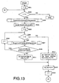
- branch path generating process S104 As shown in Fig. 13 is executed.
- branch path length d is used as a variable in addition to the variables in Fig. 7 and 8.
- Branch path length d represents the number of blocks forming one branch path except an intersection block, which is one block of the trunk path and is starting point of the branch path.
- the branch path generating process generates a branch path as following.
- An intersection block is selected from blocks that are already set as the trunk path or a branch path at the intersection block selecting process described in detail later (STEP S303).
- branch path length d is randomized from predetermined range, e.g. 1 to 3 (STEP S304).
- blocks for the branch path are selected (STEP S307) one after another in the same way as the trunk path generating process until d blocks have been selected or there has been no block available for the branch path.
- One block is selected for the branch path each time the loop from S306 to S309 is executed.
- the dead-end block flag of the block direction dir [j] adjacent from the current block is set to ON, and j is added to bk _ suu . Further, the loop #5 shown in Fig. 13 is repeated until i incremented at STEP S313 has arrived at the number of branch path bc .
- the dead-end block flag of the current block is set to ON (STEP S311) and j is added to bk _ suu (STEP S312). According to these steps, a block newly selected for the branch path becomes available for an intersection block of other branch path.
- a trunk path includes blocks 5, 13, 21, 20 and 28.
- the block 20 is selected as an intersection block and is combined with blocks 19 and 18 as a branch path.
- blocks 5, 13, 21, 20 and 28 not only blocks 5, 13, 21, 20 and 28 but also blocks 19 and 18 are available for an intersection block of a newly generated branch path.
- intersection block selecting process S303 will be described below.
- sfl [0] through sfl [bk_suu - 1] are used as variables in addition to above-mentioned variables.
- each one of sfl [0] to sfl [bk_suu - 1] is assigned at random one value of 0 to bk _ suu - 1 without repetition of same value (STEP S401).
- the sfl [k]-th block of the trunk path is selected as the current block (STEP S404). If the current block is the start block, the goal block or the dead-end block (STEP S405) or all barrier flags of the current block are ON (STEP S406), and then k is incremented from 0 to bk _ suu (STEP S407).
- a barrier flag and a connection flag of the current block toward one randomized direction are set to ON (STEP S411). Further, the barrier flag opposite to the randomized direction of the block adjacent toward the randomized direction from the current block is set to ON (STEP S412).
- the loop path generating process shown in Fig. 16 and 17 is executed.
- the loop path generating process connects two blocks that is adjacent each other and don't combine together as one path in order to form ringed paths.
- One of the blocks which has been selected for the trunk path or a branch path is randomized to be set as the current block wbk _ f (STEP S503 to S506).
- connection flag toward the randomized direction dir [k] is OFF, and the block adjacent toward the direction dir [k] from the current block exists (STEP S512). If the connection flag is ON or the adjacent block does not exist, then k is incremented (STEP S513) and STEP S511 and S512 are repeated. If all four directions of the current block does not meet the conditions of STEP S512 and S513 (STEP S510), the loop #7 shown in Fig. 16 and 17 returns to STEP S505 in order to change current block.
- the start block of one floor A may suitably be corresponded with the goal block of the floor under the floor A .
- the maze would have reasonable structure.
- rooms in a maze are generated after generating paths. Therefore, arrangement of paths is not limited under that of rooms. Consequently, the present invention can generate more complex maze.
- the trunk path that connects the start and goal blocks is generated at first so that the maze always has correct path.
- complexity of maze is easily adjustable by adjusting trunk path length dis , branch path length d , the number of branch paths bc , and the number of loops lp .
Landscapes
- Engineering & Computer Science (AREA)
- Multimedia (AREA)
- Management, Administration, Business Operations System, And Electronic Commerce (AREA)
- Processing Or Creating Images (AREA)
Abstract
Description
- The present invention relates to method, computer program and video game device for creating a maze map that includes a start point and a goal point. The start and goal points should be connected with each other via at least one route.
- In video games, a lot of kinds of map are represented as maze maps. For example, maze maps represent a dungeon, a cave, a town, a building, etc.
- Distribution media of some video games record predetermined data of maze maps. In these video games, maze maps are displayed according to the predetermined data so that the maze maps are fixed as a general.
- Instead of the predetermined data of maze maps, distribution media of other video games record maze generator programs, which generate data of random maze maps within predetermined size. If the predetermined size of maze map is enough large, the maze generator program does not generate same maze map substantially. The maze generator program may change a maze map of one building each time when the player of the video game enters the building. The maze generator program can prevent boring the player of the video game.
- Description will be made about typical maze generator program. First, the program divides a screen into m * n rectangular areas in each of which at most one room is locatable. Next, the program decides whether a room is located or not in each areas at random, and decides sizes and positions of the rooms to be located at random. Then, the program decides whether a path is located between two rooms in adjacent areas or not, and decides the route of the paths to be located at random. Here at least one path is connected to each room in order that no room is isolated from other rooms.
- Complexity of maze largely depends on complexity of the paths. According to the typical maze generator program mentioned above, however, the paths are located after the rooms are located so that the routes of the paths are tightly limited. Consequently, complexity of maze is limited so that similar mazes tend to be generated frequently.
- It is an object of the present invention to provide a method, a recording medium recorded a video game program, and a video game device for automatically generating data of maze map with higher complexity.
- According to the present invention, a method, a computer-readable storage medium and a video game device as following are provided.
- The present invention provides a method of automatically generating a maze map by computer. The maze map includes at least one floor that is composed of arrayed rectangular blocks. The floor includes a start block and a goal block, the start and goal blocks being connected with each other via at least a trunk path. The method comprises the steps of: (a) generating the floor composed of plural rectangular blocks; (b) designating one of the blocks from the floor as the start block; (c) designating a trunk path which is a sequence of blocks designated from the floor and which starts from the start block; (d) designating at least one block as an intersection block from the trunk path; and (e) designating at least one branch path which is a sequence of blocks designated from the floor and which starts from the intersection block.
- According to the method, the floor may be a two-dimensional array composed of m × n rectangular blocks (m and n are natural numbers).
- When the trunk path is composed of X rectangular blocks (X is a natural number) B1, B2, B3... BX, the step (c) may designate the blocks B1, B2, B3... BX according to the steps of: (c1) designating the start block B1 as the current block which has been currently selected as one block of the trunk path; (c2) selecting one of the blocks adjacent to the current block; (c3) designating the selected block as the next current block; and (c4) repeating the steps (c2) and (c3) until the block BX is designated.
- When the branch path is composed of X rectangular blocks (X is a natural number) B1, B2, B3... BX, the step (e) may designate the blocks B1, B2, B3 ... BX according to the steps of: (e1) designating the intersection block B1 as the current block which has been currently selected as one block of the branch path; (e2) selecting one of the blocks adjacent to the current block; (e3) designating the selected block as the next current block; and (e4) repeating the steps (e2) and (e3) until the block BX is designated.
- Further, the present invention provides a computer-readable storage medium and a video game device for generating a maze map according to the above-mentioned method.
-
- Fig. 1 shows a block-diagram of preferred
video game system 100 for maze generating program of the present invention. - Fig. 2 is a summarized flowchart of maze generating process of the present invention.
- Fig. 3 shows a floor that is composed of 8 × 8 blocks.
- Fig. 4 shows a structure of a flag group that is assigned to each block shown in Fig. 3.
- Fig. 5 is a part of the floor shown in Fig. 3 for describing relationship between structure of maze and values in a flag group.
- Fig. 6 is a table storing values of connection flags for describing relationship between structure of maze and values in a flag group.
- Fig. 7 is a flowchart of the trunk path generating process S103.
- Fig. 8 is a flowchart of the trunk path generating process S103.
- Fig. 9 is a part of the floor shown in Fig. 3 for describing the trunk path generating process S103.
- Fig. 10 is a part of the floor shown in Fig. 3 for describing the trunk path generating process S103.
- Fig. 11 is the floor shown in Fig. 3 for describing the trunk path generating process S103.
- Fig. 12 is the floor shown in Fig. 3 for describing the trunk path generating process S103.
- Fig. 13 is a flowchart of the branch path generating process S104.
- Fig. 14 is a part of the floor shown in Fig. 3 for describing the branch path generating process S104.
- Fig. 15 is a flowchart of the intersection block selecting process S303.
- Fig. 16 is a flowchart of the loop generating process S105.
- Fig. 17 is a flowchart of the loop generating process S105.
-
- Description will be made about an embodiment of the present invention. This embodiment is a
video game system 100 as shown in Fig. 1. - The
video game system 100 comprises: acontrol section 110 for controlling the operation of the whole device; animage processing section 120 for performing processing relating to image display; asound processing section 130 for performing processing relating to sound output; an auxiliarymemory control section 140 for reading out game programs and various data from a storage medium; acommunications control section 150 for reading and writing data, such as player operations, game settings, game status, and the like, and controlling input and output of other data; and amain bus 160 for connecting from theaforementioned control section 110 to thecommunications control section 150. - Next, the internal elements of the system from the
control section 110 to thecommunications control section 150 is described. - The
control section 110 comprises: a CPU 111; aperipheral device controller 112 for performing interrupt control, time control, memory control, direct memory access (DMA) transfer control, and the like; a main storage medium (main memory) 113 consisting of a RAM; and a ROM 114 storing a program, such as an operating system (OS), or the like, for controlling themain memory 113,image processing section 120 andsound processing section 130, and the like. The CPU 111 controls the whole device by executing the OS stored in the ROM 114. The CPU 111 is also equipped with a command cache and a scratch-pad memory, and it manages the actual memory. - The
image processing section 120 comprises a geometry transfer engine (GTE) 121 consisting of a co-ordinates calculating co-processor for performing processing, such as co-ordinates conversion, or the like; a graphics processing unit (GPU) 122 for performing drawing in accordance with drawing commands from the CPU 111; aframe buffer 123 for storing images drawn by theGPU 122; an image decoder (MDEC) 124 for decoding image data which has been directly converted by so-called discrete cosine transform, or the like, and then further compressed and encoded; and avideo output section 125, such as a display device, or the like. - The
sound processing section 130 includes: a sound reproduction processor (SPU) 131 for generating sounds based on instructions from the CPU 111; asound buffer 132 for storing data for sounds, music, and the like, and sound source data, read out from a CD-ROM; and asound output section 133, such as an amplifier, speaker, and the like, for outputting the sounds generated by the SPU 131. - The auxiliary
storage control section 140 comprises: a CD-ROM drive device 143 for reproducing programs, data, and the like, stored on a CD-ROM disk; adecoder 141 for decoding programs, data, and the like, stored with an appended error correction code (ECC), for example; and a CD-ROM buffer 142 for temporarily storing data reproduced by the CD-ROM drive device 143. - The
communications control section 150 comprises: acommunications control device 151 for controlling communications with the CPU 111 through themain bus 160; acontroller 152 for inputting instructions from a user; and adetachable memory card 153, which is a readable and writable storage medium for storing game settings, and the like. - Next, the basic operation of the
video game system 100 will be described. - When the power supply to the
video game system 100 is switched on, the OS stored in the ROM 114 is executed by the CPU 111, and theimage processing section 120,sound processing section 130, and the like, are put into active states under the control of the OS. Firstly, the OS performs initialization, such as operational verification, and the like, of the overall device, whereupon it controls the auxiliarystorage control section 140 and executes a game program stored on a CD-ROM accommodated in the CD-ROM drive device 143. - Then, the CPU 111 controls the
image processing section 120,sound processing section 130, and the like, in accordance with the game program being executed and the inputs performed by the player via thecontroller 152, and it displays images by thevideo output section 125, whilst also outputting sounds, such as sound effects, music, and the like, by thesound output section 133. If the game is temporarily suspended, then the current game status is written to thememory card 153 as saved data. When a suspended game is restarted, this saved data is read out and the status of the game in progress is recreated. - The maze generating process of the present invention is incorporated into a video game program recorded in a CD-ROM disk as a maze generator program. According to the maze generator program, the CPU 111 generates data that represents a structure of a maze. According to the data, the
GTE 121 and theGPU 122 generate image signals for drawing two/three-dimensional maze. The image signals are merged with other image signals and output to thevideo output section 125 as video signals. - Turning now to Fig. 2, the process of the
maze generator program 1 will be described hereinafter. Roughly speaking, themaze generator program 1 comprises steps S101 through S106. In the description below, themaze generator program 1 generates a maze on a floor composed of 8 × 8 blocks as shown in Fig. 3. The number written in each of the blocks is called as a block number. The maze includes a trunk path and a plurality of branch paths. The trunk path connects a start block and a goal block. The branch paths are extended from the trunk path to a dead-end block. All paths have one block width. - Each of the blocks is related to a group of flags. The group of flags is called as a flag group hereinafter. As shown in Fig. 4, one flag group is composed of twelve flags (bit [0] through bit [11]).
- Each of the bits [0], [1], [2] and [3] corresponding to directions east, west, south and north is named as a connection flag. A connection flag represents that the block forms a part of a path with a block adjacent to the block toward its corresponding direction.
- Each of the bits [4], [5], [6] and [7] corresponding to directions east, west, south and north is named as a barrier flag. A barrier flag represents that its corresponding direction of the block is unavailable for generating a path.
- The bit [8] is named as a path flag and represents that the block is a part of a path.
- The bit [9] is named as a start block flag representing that the block is the start block of the maze.
- The bit [10] is named as a goal block flag representing that the block is the goal block of the maze.
- The bit [11] is named as a dead-end block flag representing that the block is the dead-end block.
- According to the
maze generator program 1, a map of maze is represented as a plurality of flag groups. In a part of a map shown in Fig. 5, dark blocks (block No. = 9, 10, 11, 18, 19, 25) represent that each of them is a part of a path. White blocks (block No. = 17, 26) represent that each of them is impassable block, such as a wall or a pillar of the maze. This map is represented as connection flags shown in Fig. 6. For example, as shown in Fig. 5, theblock 18 connects with theblocks blocks block 18 "0101"; the bits [0] and [2] are ON (1) and thebits - Turning again to Fig. 2, each of STEPS S101 through S106 will be roughly described below.
- At STEP S101, following values are determined as initial-values for generating a maze; trunk path length dis, the number of branch paths bc, the number of loops lp, block number of the start block st. The trunk path length dis represents the number of blocks that are composed of a trunk path from a start block through a goal block. The number of branch path bc represents the number of branch paths that extend from the trunk path. The number of loop lp represents the number of ringed paths in the maze. The block number of a start block st represents the block number of the start block of the maze.
- Furthermore, variables are initialized as following. Hereinafter, a flag group related to a block number n is represented as f [n]. All flags (bit [0] through bit [11]) of f [0] through f [63] are set to zero except that the start block flag of the start block, namely, the bit [9] of the flag group f [st] is set to one.
- At STEP S102, the barrier flags corresponding to the sides of the floor are set to ON in order to inhibit from generating a path out of the floor. With referring to Fig. 3, each bit [6] of the south side blocks 0 through 7 is set to ON. Similarly, each bit [4] of the east side blocks 7, 15, 23, 31, 39, 47, 55 and 63 is set to ON. Each bit [5] of the west side blocks 0, 8, 16, 24, 32, 40, 48 and 56 is set to ON. Each bit [7] of the north side blocks is set to ON.
- At STEP S103, a trunk path generating process is executed. The trunk path generating process selects adjoining dis blocks from the floor as the blocks of the trunk path. Detail of the trunk path generating process will be described in the following section titled "(3) Trunk path generating process".
- At STEP S104, a branch path generating process is executed. The branch path generating process selects bc blocks from the trunk path and generates branch paths from the bc blocks. Detail of the branch path generating process will be described in the following section titled "(4) Branch path generating process".
- At STEP S105, a loop path generating process is executed. The loop path generating process selects one block from the trunk path and another block from one of the branch paths, then generates a path between the two selected blocks to generate one loop path. The loop path generating process repeats above-mentioned process ls times in order to generate ls loop paths. Detailed description of the process will be described in the following section titled "(5) Loop path generating process".
- One end of a branch path is connected to the trunk path and the other end is dead-end. STEP S106 judges whether neighboring blocks of a dead-end block are already used as one block of the trunk, branch or loop path, then combines the unused blocks in order to generate a room.
- With reference to Fig. 7 and 8, the trunk path generating process will be described in detail. In Fig. 7 and 8, following variables are used. i, j, k and count are loop counters for deciding terminal condition of a loop. bk_suu is amount of blocks that is already used for paths. wbk_f is the flag group of the block which is currently operated (hereinafter referred to as current block). next_no is one of block numbers each of which represents that the block is adjacent to the current block and is available for combining with the current block into a path. Each of dir [0], dir [1], dir [2] and dir [3] represents one of four directions east, west, south and north, and is assigned one of values 0 (east), 1 (west), 2 (south) and 3 (north) without repetition (STEP S204).
- At STEP S206, the barrier flag corresponding to the direction dir [j] of the current block is checked. When the barrier flag is OFF, first, it is checked whether the block next_no exists in the floor (STEP S208), and if the block next_no exists, then it is checked whether the path flag of the block next_no is ON (STEP S212).
- If the path flag is OFF at STEP S212, then both the connection flag to direction dir [j] of the current block and the connetion flag opposite to direction dir [j] of the block next_no are set to ON (STEP S213).
- If the path flag is ON at STEP S212, then count is incremented (STEP S214). Next, whether the path flag is ON or OFF at STEP S212, both the barrier flag to direction dir [j] of the current block and the barrier flag opposite to direction dir [j] of the block next_no are set to ON (STEP S215).
- If the barrier flag to direction dir [j] of the current block is ON, or if the block next_no does not exist in the floor, then count and j are incremented (STEP S209, S210). Next, if j is under four, then a barrier flag to new direction of the current block is checked, and if j is four, namely, if all barrier flags of the current block are ON, STEP S211 is next to STEP S216.
- At STEP S216, count is compared with four. If count is under four, then the path flag of the current block is set to ON (STEP S217).
- Next, it is checked whether each one of four blocks adjacent to the block next_no is already used as a part of path or not. If the adjacent block is already used, the barrier flag of the block next_no toward the adjacent block is set ON and the barrier flag of the adjacent block toward the block next_no is set ON (STEP S218). According to STEP S218, the trunk path has no loop.
- Turning to Fig. 9, it is described when the current block is
block 9 and the block next_no is theblock 1 as an example. In this case, when the north block of theblock 1 is checked, theblock 9 is already used as a part of a path. Consequently, the north barrier flag (seventh bit) of theblock 1 is set to ON and the south barrier flag (sixth bit) of theblock 9 is set to ON. Next, i is decremented by the same time theloop # 2 shown in Fig. 7 and 8 has been repeated (STEP S219). Then, i is incremented by one (STEP S220). Next, the block next_no is set as a new current block. After each one time theloop # 3 shown in Fig. 7 and 8 is repeated, one block is added to the trunk path. - Turning again to STEP S216, if count is equal to four, the process is continued as following. If the block previous to the current block exists, then the previous block is set as the current block again (STEP S225) and k is incremented (STEP S226).
- With reference to Fig. 10 as an example, the trunk path is composed of the
block block 1 and the last current block is theblock 10. - When the
block 10 is the current block, the previous current block (the block 9) is set as the current block again. If the start block (the block 1), which has no previous block, is set as the current block again because of repetition of setting back to previous block, then the goal block flag of the last current block (the block 10) is set to ON (STEP S227), the ending process, which will be described later, is executed (STEP S228), and the trunk path generating process S103 is ended. In this case, the number of blocks of the trunk path is not always equal to the trunk path length dis. - When i arrives at the trunk path length dis according to repetition of the loop #3 (STEP S202), the ending process at STEP S222 is executed, bk_suu is set to i+1 (STEP S223), and the trunk path generating process is ended.
- bk_suu represents amount of the blocks each of that has already been set as a part of a path, and further, each block of the path is numbered from 0 to bk_suu - 1 in order. These numbers are given to not only the blocks of the trunk path, but also the blocks of the branch path.
- Above-mentioned ending process (STEP S222 and S228) is described as following. When the
loop # 2 is executed at least one time (when k becomes over zero) during the trunk path generating process S103, previous current block has been set back as current block again at least one time because next current block does no exist. - In this case, the trunk path would separate some paths as shown in Fig. 11. In Fig. 11, the trunk path separates at the
blocks blocks block 15 that connects unnecessary block to the trunk path; the north connection flag of theblock 20; and barrier flags where "X"s are marked in Fig. 12. - After generating the trunk path, the branch path generating process S104 as shown in Fig. 13 is executed. In Fig. 13, branch path length d is used as a variable in addition to the variables in Fig. 7 and 8. Branch path length d represents the number of blocks forming one branch path except an intersection block, which is one block of the trunk path and is starting point of the branch path.
- The branch path generating process generates a branch path as following. First, An intersection block is selected from blocks that are already set as the trunk path or a branch path at the intersection block selecting process described in detail later (STEP S303). Next, branch path length d is randomized from predetermined range, e.g. 1 to 3 (STEP S304).
- Then, blocks for the branch path are selected (STEP S307) one after another in the same way as the trunk path generating process until d blocks have been selected or there has been no block available for the branch path. One block is selected for the branch path each time the loop from S306 to S309 is executed.
- If j arrives at d, then the dead-end block flag of the block direction dir [j] adjacent from the current block is set to ON, and j is added to bk_suu. Further, the
loop # 5 shown in Fig. 13 is repeated until i incremented at STEP S313 has arrived at the number of branch path bc. - If there is no adjacent block available for the branch path, namely, the current block is at dead-end, then the dead-end block flag of the current block is set to ON (STEP S311) and j is added to bk_suu (STEP S312). According to these steps, a block newly selected for the branch path becomes available for an intersection block of other branch path.
- For example, in Fig. 14, a trunk path includes
blocks block 20 is selected as an intersection block and is combined withblocks - With reference to Fig. 15, above-mentioned intersection block selecting process S303 will be described below. In Fig. 15, sfl [0] through sfl [bk_suu - 1] are used as variables in addition to above-mentioned variables.
- First, each one of sfl [0] to sfl [bk_suu - 1] is assigned at random one value of 0 to bk_suu - 1 without repetition of same value (STEP S401).
- Next, the sfl [k]-th block of the trunk path is selected as the current block (STEP S404). If the current block is the start block, the goal block or the dead-end block (STEP S405) or all barrier flags of the current block are ON (STEP S406), and then k is incremented from 0 to bk_suu (STEP S407).
- If the current block is neither the start block, nor the goal block, nor the dead-end block and all barrier flags of the current block are OFF, then a barrier flag and a connection flag of the current block toward one randomized direction are set to ON (STEP S411). Further, the barrier flag opposite to the randomized direction of the block adjacent toward the randomized direction from the current block is set to ON (STEP S412).
- After the trunk path generating process and the branch path generating process has been executed, the loop path generating process shown in Fig. 16 and 17 is executed. The loop path generating process connects two blocks that is adjacent each other and don't combine together as one path in order to form ringed paths.
- One of the blocks which has been selected for the trunk path or a branch path is randomized to be set as the current block wbk_f (STEP S503 to S506).
- After confirming that the current block is neither the start block, nor the goal block, nor the dead-end block, it is checked that the connection flag toward the randomized direction dir [k] is OFF, and the block adjacent toward the direction dir [k] from the current block exists (STEP S512). If the connection flag is ON or the adjacent block does not exist, then k is incremented (STEP S513) and STEP S511 and S512 are repeated. If all four directions of the current block does not meet the conditions of STEP S512 and S513 (STEP S510), the
loop # 7 shown in Fig. 16 and 17 returns to STEP S505 in order to change current block. - If there is a direction where both conditions of STEP S512 and S513 are "NO", the path flag of the block adjacent toward dir [k] from wbk_f is checked (STEP S514). If the path flag is ON, corresponding connection flag and barrier flag of the current block and its adjacent block is set to ON (STEP S515), i is incremented (STEP S516), and the
loop # 9 shown in Fig. 16 and 17 returns to STEP S502. STEP S501 to S516 are repeated until i arrives at the number of loop lp. - Above-mentioned embodiment have been described with reference to generating a maze map which is composed of one floor which is composed of 8 × 8 blocks. Therefore, that skilled in the art can apply the essence of the present invention to generating a maze map which is composed of plural floors according to repeat the method of above-mentioned embodiment and further, to generating a maze map whose floor is composed of m × n (m and n are natural numbers) blocks.
- When a maze map is composed of plural floors each of which is composed of blocks of the same array, the start block of one floor A may suitably be corresponded with the goal block of the floor under the floor A. In this case, the maze would have reasonable structure.
- According to the present invention, rooms in a maze are generated after generating paths. Therefore, arrangement of paths is not limited under that of rooms. Consequently, the present invention can generate more complex maze.
- Further, according to the present invention, the trunk path that connects the start and goal blocks is generated at first so that the maze always has correct path.
- And further, according to the present invention, complexity of maze is easily adjustable by adjusting trunk path length dis, branch path length d, the number of branch paths bc, and the number of loops lp.
Claims (15)
- A method of automatically generating a maze map by computer, the maze map including at least one floor that is composed of arrayed rectangular blocks, the floor including a start block and a goal block, the start and goal blocks being connected with each other via at least a trunk path, characterized in that the method comprises the steps of:(a) generating the floor composed of plural rectangular blocks;(b) designating one of the blocks from the floor as the start block;(c) designating a trunk path which is a sequence of blocks designated from the floor and which starts from the start block;(d) designating at least one block as an intersection block from the trunk path; and(e) designating at least one branch path which is a sequence of blocks designated from the floor and which starts from the intersection block.
- The method claimed in claim 1, characterized in that the floor is a two-dimensional array composed of m × n rectangular blocks (m and n are natural numbers).
- The method claimed in claim 1 or 2, characterized in that when the trunk path is composed of X rectangular blocks (X is a natural number) B1, B2, B3... BX, the step (c) designates the blocks B1, B2, B3... BX according to the steps of:(c1) designating the start block B1 as the current block which has been currently selected as one block of the trunk path;(c2) selecting one of the blocks adjacent to the current block;(c3) designating the selected block as the next current block; and(c4) repeating the steps (c2) and (c3) until the block BX is designated.
- The method claimed in any of claims 1 to 3, characterized in that when the branch path is composed of X rectangular blocks (X is a natural number) B1, B2, B3... BX, the step (e) designates the blocks B1, B2, B3... BX according to the steps of:(e1) designating the intersection block B1 as the current block which has been currently selected as one block of the branch path;(e2) selecting one of the blocks adjacent to the current block;(e3) designating the selected block as the next current block; and(e4) repeating the steps (e2) and (e3) until the block BX is designated.
- A method of automatically generating a maze map by computer, the maze map being composed of a plurality of floors each of that is composed of arrayed rectangular blocks, the floor including both a start block and a goal block, the start and goal blocks being connected with each other via at least a trunk path, characterized in that the method generates at least one of the floors according to the method claimed in any of claims 1 to 4.
- A computer-readable storage medium storing a program for generating a maze map, the maze map including at least one floor that is composed of arrayed rectangular blocks, the floor including a start block and a goal block, the start and goal blocks being connected with each other via at least a trunk path, characterized in that the program comprises the processes of:(a) generating the floor composed of plural rectangular blocks;(b) designating one of the blocks from the floor as the start block;(c) designating a trunk path which is a sequence of blocks designated from the floor and which starts from the start block;(d) designating at least one block as an intersection block from the trunk path; and(e) designating at least one branch path which is a sequence of blocks designated from the floor and which starts from the intersection block.
- The computer-readable storage medium claimed in claim 6, characterized in that the floor is a two-dimensional array composed of m × n rectangular blocks (m and n are natural numbers).
- The computer-readable storage medium claimed in claim 6 or 7, characterized in that when the trunk path is composed of X rectangular blocks (X is a natural number) B1, B2, B3 ... BX, the process (c) designates the blocks B1, B2, B3... BX according to the processes of:(c1) designating the start block B1 as the current block which has been currently selected as one block of the trunk path;(c2) selecting one of the blocks adjacent to the current block;(c3) designating the selected block as the next current block; and(c4) repeating the processes (c2) and (c3) until the block BX is designated.
- The computer-readable storage medium claimed in any of claims 6 to 8, characterized in that when the branch path is composed of X rectangular blocks (X is a natural number) B1, B2, B3... BX, the process (e) designates the blocks B1, B2, B3... BX according to the processes of:(e1) designating the intersection block B1 as the current block which has been currently selected as one block of the branch path;(e2) selecting one of the blocks adjacent to the current block;(e3) designating the selected block as the next current block; and(e4) repeating the processes (e2) and (e3) until the block BX is designated.
- A computer-readable storage medium storing a program for generating a maze map, the maze map being composed of a plurality of floors each of that is composed of arrayed rectangular blocks, the floor including both a start block and a goal block, the start and goal blocks being connected with each other via at least a trunk path, characterized in that the program generates at least one of the floors according to the program claimed in any of claims 6 to 9.
- A video game device comprising the computer-readable storage medium claimed in any of claims 6 to 10, characterized in that the video game device is operable according to the program
- A video game device for generating a maze map, the maze map including at least one floor that is composed of arrayed rectangular blocks, the floor including a start block and a goal block, the start and goal blocks being connected with each other via at least a trunk path, characterized in that the video game device comprises:(a) means for generating the floor composed of plural rectangular blocks;(b) means for designating one of the blocks from the floor as the start block;(c) means for designating a trunk path which is a sequence of blocks designated from the floor and which starts from the start block;(d) means for designating at least one block as an intersection block from the trunk path; and(e) means for designating at least one branch path which is a sequence of blocks designated from the floor and which starts from the intersection block.
- The video game device claimed in claim 12, characterized in that the floor is a two-dimensional array composed of m × n rectangular blocks (m and n are natural numbers).
- The video game device claimed in claim 12 or 13, characterized in that when the trunk path is composed of X rectangular blocks (X is a natural number) B1, B2, B3... BX, means (c) designates the blocks B1, B2, B3... BX and comprises:(c1) means for designating the start block B1 as the current block which has been currently selected as one block of the trunk path;(c2) means for selecting one of the blocks adjacent to the current block;(c3) means for designating the selected block as the next current block; and(c4) means for repeatedly activating means (c2) and (c3) until the block BX is designated.
- The video game device claimed in any of claims 12 to 14, characterized in that: when the branch path is composed of X rectangular blocks (X is a natural number) B1, B2, B3... BX, means (e) designates the blocks B1, B2, B3... BX and comprises:(e1) means for designating the intersection block B1 as the current block which has been currently selected as one block of the branch path;(e2) means for selecting one of the blocks adjacent to the current block;(e3) means for designating the selected block as the next current block; and(e4) means for repeatedly activating means (e2) and (e3) until the block BX is designated.
Applications Claiming Priority (2)
| Application Number | Priority Date | Filing Date | Title |
|---|---|---|---|
| JP28074599 | 1999-09-30 | ||
| JP28074599A JP3270929B2 (en) | 1999-09-30 | 1999-09-30 | Maze automatic generation method, recording medium, and video game device |
Publications (2)
| Publication Number | Publication Date |
|---|---|
| EP1088574A2 true EP1088574A2 (en) | 2001-04-04 |
| EP1088574A3 EP1088574A3 (en) | 2001-08-08 |
Family
ID=17629375
Family Applications (1)
| Application Number | Title | Priority Date | Filing Date |
|---|---|---|---|
| EP00121228A Ceased EP1088574A3 (en) | 1999-09-30 | 2000-09-29 | Method, computer-readable storage medium and video game device for automatically generating a maze map with at least one correct path |
Country Status (3)
| Country | Link |
|---|---|
| US (1) | US6347995B1 (en) |
| EP (1) | EP1088574A3 (en) |
| JP (1) | JP3270929B2 (en) |
Cited By (2)
| Publication number | Priority date | Publication date | Assignee | Title |
|---|---|---|---|---|
| CN105492091A (en) * | 2013-09-18 | 2016-04-13 | 喀普康有限公司 | Game device, game device control method, and recording medium |
| CN111494958A (en) * | 2020-04-20 | 2020-08-07 | 张洋 | Method and device for randomly generating maze map |
Families Citing this family (16)
| Publication number | Priority date | Publication date | Assignee | Title |
|---|---|---|---|---|
| DE10148126A1 (en) * | 2001-09-28 | 2003-04-17 | Atronic Int Gmbh | Method for determining a course of a playing field, consisting of a plurality of playing fields that connect a starting field with a target field |
| JP3883522B2 (en) | 2003-05-09 | 2007-02-21 | 任天堂株式会社 | GAME DEVICE AND GAME PROGRAM |
| JP3934081B2 (en) | 2003-05-12 | 2007-06-20 | 任天堂株式会社 | GAME DEVICE AND GAME PROGRAM |
| US20060030405A1 (en) * | 2004-08-06 | 2006-02-09 | Alan Robertson | Apparatus, system, and method for automated generation of a virtual environment for software applications |
| CN100421119C (en) * | 2006-07-11 | 2008-09-24 | 北京金山软件有限公司 | Method for drawing map in game |
| US7928983B2 (en) * | 2007-06-04 | 2011-04-19 | Daedal Doodle, LLC | Interactive labyrinth curve generation and applications thereof |
| US8520004B2 (en) * | 2007-06-04 | 2013-08-27 | Daedal Doodle, LLC | Interactive labyrinth curve generation and applications thereof |
| TWI380701B (en) * | 2007-12-14 | 2012-12-21 | Altek Corp | Image maze generating system and method thereof |
| JP4871308B2 (en) * | 2008-01-31 | 2012-02-08 | 株式会社スクウェア・エニックス | Block game program |
| US20110165939A1 (en) * | 2010-01-05 | 2011-07-07 | Ganz | Method and system for providing a 3d activity in a virtual presentation |
| US8648855B2 (en) * | 2010-01-12 | 2014-02-11 | Daedal Doodle, LLC | Methods for creating developable surfaces |
| US8836719B2 (en) | 2010-04-23 | 2014-09-16 | Ganz | Crafting system in a virtual environment |
| JP6343067B2 (en) * | 2013-09-18 | 2018-06-13 | 株式会社カプコン | GAME PROGRAM AND GAME DEVICE |
| KR101961304B1 (en) * | 2017-09-08 | 2019-03-22 | 충북대학교 산학협력단 | Method for generating maze |
| JP7118107B2 (en) | 2020-04-21 | 2022-08-15 | グリー株式会社 | Program, game control method, and information processing device |
| CN113827976A (en) * | 2021-09-28 | 2021-12-24 | 完美世界(重庆)软件科技有限公司 | Random map generation method and device, storage medium and computing equipment |
Family Cites Families (11)
| Publication number | Priority date | Publication date | Assignee | Title |
|---|---|---|---|---|
| US3625516A (en) * | 1970-01-26 | 1971-12-07 | Black Tulip Toy Co Inc | Invisible maze puzzle |
| US4089524A (en) * | 1977-01-18 | 1978-05-16 | Gremlin Industries, Inc. | Digitally controlled electronic game |
| US4240638A (en) * | 1978-01-06 | 1980-12-23 | Marvin Glass & Associates | Microprocessor controlled game apparatus |
| US4341385A (en) * | 1980-01-24 | 1982-07-27 | Doyle Holly Thomis | Electronic board game apparatus |
| US4323242A (en) * | 1980-09-23 | 1982-04-06 | Rosenfeld Peter E | Electronic maze game |
| US4511143A (en) * | 1982-08-20 | 1985-04-16 | Sankrithi Mithra M K V | Electronic maze game |
| US4674753A (en) * | 1986-02-03 | 1987-06-23 | Richard Hochstim | Boardless maze game |
| USRE35314E (en) * | 1986-05-20 | 1996-08-20 | Atari Games Corporation | Multi-player, multi-character cooperative play video game with independent player entry and departure |
| US4850592A (en) * | 1988-04-06 | 1989-07-25 | Winter Jerry A | Mouse maze game |
| US5050883A (en) * | 1990-02-07 | 1991-09-24 | Adolph E. Goldfarb | Self-contained competitive game for developing spatial sense in young children |
| US6273420B1 (en) * | 1999-07-13 | 2001-08-14 | Kenneth P. Brooks | Electronic maze game |
-
1999
- 1999-09-30 JP JP28074599A patent/JP3270929B2/en not_active Expired - Fee Related
-
2000
- 2000-09-29 EP EP00121228A patent/EP1088574A3/en not_active Ceased
- 2000-10-02 US US09/676,666 patent/US6347995B1/en not_active Expired - Lifetime
Non-Patent Citations (1)
| Title |
|---|
| None |
Cited By (6)
| Publication number | Priority date | Publication date | Assignee | Title |
|---|---|---|---|---|
| CN105492091A (en) * | 2013-09-18 | 2016-04-13 | 喀普康有限公司 | Game device, game device control method, and recording medium |
| EP3047885A4 (en) * | 2013-09-18 | 2017-07-19 | Capcom Co., Ltd. | Game device, game device control method, and recording medium |
| US9925462B2 (en) | 2013-09-18 | 2018-03-27 | Capcom Co., Ltd. | Game device, game device control method, and recording medium |
| CN105492091B (en) * | 2013-09-18 | 2019-01-15 | 喀普康有限公司 | The control method of game device and game device |
| CN111494958A (en) * | 2020-04-20 | 2020-08-07 | 张洋 | Method and device for randomly generating maze map |
| CN111494958B (en) * | 2020-04-20 | 2023-06-16 | 张洋 | Method and device for randomly generating maze map |
Also Published As
| Publication number | Publication date |
|---|---|
| JP2001096067A (en) | 2001-04-10 |
| EP1088574A3 (en) | 2001-08-08 |
| JP3270929B2 (en) | 2002-04-02 |
| US6347995B1 (en) | 2002-02-19 |
Similar Documents
| Publication | Publication Date | Title |
|---|---|---|
| EP1088574A2 (en) | Method, computer-readable storage medium and video game device for automatically generating a maze map with at least one correct path | |
| US6146277A (en) | Command input method and recording medium | |
| US5634850A (en) | Image processing device and method | |
| EP0847782B1 (en) | Video game machine and medium where video game program is stored | |
| EP1088573B1 (en) | Method and a video game system of generating a field map | |
| JP3433918B2 (en) | Game system, display image forming method in game system, and computer-readable recording medium storing game program | |
| EP1795240B1 (en) | Game machine, game machine control method, information recording medium, and program | |
| JP3974136B2 (en) | Program, light arrangement method, and image generation apparatus | |
| KR20010033214A (en) | Recording medium, image processing device and image processing method | |
| EP0836871A2 (en) | Video game machine for playing video ball game and storage medium storing video ball game program | |
| KR20070029134A (en) | Game apparatus and game program | |
| JP2000279637A (en) | Game device, game display control method, and computer- readable record medium | |
| EP1161742A1 (en) | System for and method of implementing refraction mapping | |
| JP3617839B2 (en) | GAME SOUND CONTROL PROGRAM, GAME SOUND CONTROL METHOD, AND GAME DEVICE | |
| EP0842681B1 (en) | Image processor, image processing method and game machine and recording medium | |
| JP2000107441A (en) | Game device, topographic pattern forming method, and information recording medium | |
| KR20070088812A (en) | Image generation device, automatic arrangement method, recording medium, and program | |
| JPH11144087A (en) | Image generating device and information storage medium | |
| JP4706939B2 (en) | GAME MACHINE, GAME PROCESSING METHOD, AND RECORDING MEDIUM CONTAINING PROGRAM | |
| EP1072298A1 (en) | Display method for a confrontation type video game for displaying different information to players, storage medium and video game system | |
| JP2005218706A (en) | Game apparatus and game program | |
| JP4233065B2 (en) | GAME DEVICE AND INFORMATION STORAGE MEDIUM | |
| JP3943097B2 (en) | Game software and game apparatus having automatic arrangement function of grass object | |
| JP2001184515A (en) | Image forming system and an information storage medium | |
| JP2986451B2 (en) | Computer-readable recording medium storing selected icon display method, game system, and game program |
Legal Events
| Date | Code | Title | Description |
|---|---|---|---|
| PUAI | Public reference made under article 153(3) epc to a published international application that has entered the european phase |
Free format text: ORIGINAL CODE: 0009012 |
|
| 17P | Request for examination filed |
Effective date: 20001027 |
|
| AK | Designated contracting states |
Kind code of ref document: A2 Designated state(s): DE FR GB |
|
| AX | Request for extension of the european patent |
Free format text: AL;LT;LV;MK;RO;SI |
|
| PUAL | Search report despatched |
Free format text: ORIGINAL CODE: 0009013 |
|
| AK | Designated contracting states |
Kind code of ref document: A3 Designated state(s): AT BE CH CY DE DK ES FI FR GB GR IE IT LI LU MC NL PT SE |
|
| AX | Request for extension of the european patent |
Free format text: AL;LT;LV;MK;RO;SI |
|
| AKX | Designation fees paid |
Free format text: DE FR GB |
|
| RAP1 | Party data changed (applicant data changed or rights of an application transferred) |
Owner name: KONAMI CORPORATION |
|
| RAP1 | Party data changed (applicant data changed or rights of an application transferred) |
Owner name: KONAMI DIGITAL ENTERTAINMENT CO., LTD. |
|
| STAA | Information on the status of an ep patent application or granted ep patent |
Free format text: STATUS: THE APPLICATION HAS BEEN REFUSED |
|
| 18R | Application refused |
Effective date: 20110424 |