EP1093929A2 - Ink jet printer and its preliminary driving method - Google Patents
Ink jet printer and its preliminary driving method Download PDFInfo
- Publication number
- EP1093929A2 EP1093929A2 EP00122312A EP00122312A EP1093929A2 EP 1093929 A2 EP1093929 A2 EP 1093929A2 EP 00122312 A EP00122312 A EP 00122312A EP 00122312 A EP00122312 A EP 00122312A EP 1093929 A2 EP1093929 A2 EP 1093929A2
- Authority
- EP
- European Patent Office
- Prior art keywords
- printing
- head
- waveform
- preliminary
- ink
- Prior art date
- Legal status (The legal status is an assumption and is not a legal conclusion. Google has not performed a legal analysis and makes no representation as to the accuracy of the status listed.)
- Granted
Links
Images


Classifications
-
- B—PERFORMING OPERATIONS; TRANSPORTING
- B41—PRINTING; LINING MACHINES; TYPEWRITERS; STAMPS
- B41J—TYPEWRITERS; SELECTIVE PRINTING MECHANISMS, i.e. MECHANISMS PRINTING OTHERWISE THAN FROM A FORME; CORRECTION OF TYPOGRAPHICAL ERRORS
- B41J19/00—Character- or line-spacing mechanisms
- B41J19/18—Character-spacing or back-spacing mechanisms; Carriage return or release devices therefor
- B41J19/20—Positive-feed character-spacing mechanisms
- B41J19/202—Drive control means for carriage movement
Landscapes
- Ink Jet (AREA)
- Particle Formation And Scattering Control In Inkjet Printers (AREA)
Abstract
Description
- The present invention relates to an ink jet printer and its preliminary driving method and, in particular, to an ink jet printer for driving a head in advance in the case where printing is performed by discharging ink from the nozzle of the head, and to its preliminary driving method.
- In a conventional ink jet printer in which ink is discharged from the nozzle of a head to print a letter (or to form an image), the ink is always in contact with air at the opening of the nozzle and hence gradually becomes dry, which inevitably produces a phenomenon in which the viscosity of the ink becomes higher.
- Since the higher viscosity of the ink increases the surface tension of the ink, the ink is hard to discharge if a force to discharge the ink is the same as before. As a result, this changes the direction of discharging of the ink or produces variations in the speed of the drop of the ink to reduce the quality of an image to be produced.
- Accordingly, an ink jet printer in which, in the case where ink is not discharged for a predetermined time, ink is discharged to a region not to be printed and then new ink is prepared in the opening of a nozzle to discharge the ink to a region to be printed has been known as a first conventional technology (see JP-A-9-164694).
- As a second conventional technology has been known a method of reducing the viscosity of ink by applying a driving waveform onto a head to the extent in which the ink is not discharged to sway the ink in the opening of the nozzle (see JP-A-64-38246). As a third conventional technology has been known an ink jet printer having a first memory device for memorizing a plurality of preliminary discharging data to preliminarily drive a head and a second memory device for memorizing a specific preliminary discharging pattern data selected from the plurality of preliminary discharging data (see JP-A-8-52885).
- The ink jet printer of the above-mentioned third conventional technology performs a preliminary driving motion of discharging the ink from all nozzles at the same time to recover clogging in nozzles in low temperature surroundings. In this ink jet printer, in the case where a plurality of nozzles are divided into groups of a predetermined number of nozzles end each of the divided groups of nozzles is filled with the ink of different color, in order to prevent the inks from being mixed with each other, a preliminary driving motion is performed such that each ink is discharged a different number of dischargings according to the color of the ink and that the discharging motions of the inks of the plurality of colors are finished at the same time, or a preliminary discharging data is selected according to the condition of the head.
- The above-mentioned conventional ink jet printers present a problem that because the preliminary driving motion is performed before the printer starts printing, there is a short open time before the printer starts printing actually and the ink becomes dry during the short open time to produce a considerable effect on the quality of printing.
- The present invention has been made in view of the above circumstances, and it is the object of the present invention to provide an ink jet printer capable of shortening the time between a preliminary driving motion and a printing motion to improve the quality of printing and its preliminary driving method.
- An ink jet printer in accordance with the present invention is an ink jet printer for performing printing by discharging ink from a plurality of nozzles mounted on a head moving with a carrier. The ink jet printer comprises a position detecting device, a preliminary waveform generating device, and a printing driving waveform generating device. The position detecting device detects the present position of the head. The preliminary waveform generating device compares the output of the position detecting device with a preliminary waveform starting position which is previously set to detect that the head reaches the preliminary waveform starting position. Then, the preliminary waveform generating device generates a preliminary waveform during the preliminary waveform driving region previously set in the period in which the head moves from the position where it is detected that the head reaches the preliminary waveform starting position to a printing starting position. The printing driving waveform generating device compares the output of the position detecting device with the printing starting position previously set just after the preliminary waveform driving region to detect that the head reaches the printing starting position. Then, The printing driving waveform generating device generates a printing driving waveform during a printing region previously set after the tine when it is detected that the head reaches the printing starting position. The preliminary waveform sways ink in the opening of the nozzle of the head to the extent that the ink is not discharged from the opening of the nozzle and wherein the printing driving waveform discharges the ink from the opening of the nozzle of the head.
- In the present invention, the preliminary waveform driving region is made in the period of movement of the head just after the head starts moving for printing until it reaches the printing starting position, and the preliminary waveform generated in the preliminary waveform driving region sways the ink in the opening of the nozzle of the head to the extent where the ink is not discharged to reduce the viscosity of the ink and the printing is performed in the usual printing region immediately after the head passes the preliminary waveform driving region. Accordingly, this can drive the head for printing before the viscosity of the ink, which is reduced by the preliminary driving motion, is increased.
- Also, a method of preliminarily driving an ink jet printer in accordance with the present invention is a method of preliminarily driving the head of an ink jet printer just before ink is discharged from a plurality of nozzles mounted on the head moving with a carrier to perform printing. The method of preliminarily driving an ink jet printer in accordance with the present invention comprises a first step of detecting that the head reaches a preliminary waveform starting position previously set after the head starts moving to perform printing. The method further comprises a second step of generating a preliminary waveform during a preliminary waveform driving region previously set, in the period in which the head moves from the position where it is detected that the head reaches the preliminary waveform starting position to a printing starting position. The method further comprises a third step of swaying the ink in the head by the preliminary waveform to the extent that the ink is not discharged from the opening of the nozzle of the head.
- In the present invention, the preliminary waveform driving region is made in the period of movement of the head just after the head starts moving for printing until it reaches the printing starting position. The preliminary waveform generated in the preliminary waveform driving region sways the ink in the opening of the nozzle of the head to the extent where the ink is not discharged, whereby the viscosity of the ink can be reduced just before the usual printing is started. Also, the present invention is characterized in that a printing driving waveform is inputted to the head instead of the preliminary waveform when the head reaches the printing starting position after the head passes the preliminary wave form driving region and that the head starts printing based on the printing driving waveform.
- Preferred embodiments in accordance with the present invention will be described in detail with reference to the following figures, in which:
- FIG. 1 is a block diagram showing one preferred embodiment of an ink jet printer in accordance with the present invention;
- FIG. 2 is a block diagram showing the structure of a driving waveform generating circuit;
- FIG. 3 is a circuit system diagram showing one preferred embodiment of a main part in FIG. 2;
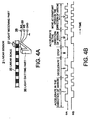
- FIGs. 4A and 4B are illustrations illustrating the constitution and motion of a linear sensor in FIG. 1;
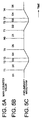
- FIGs. 5A through 5G are time charts to illustrate the motion in FIG. 1 to FIG. 3;
- FIG. 6 is a signal waveform illustration showing a preliminary waveform and a printing driving waveform in Fig. 1 to fig. 3; and
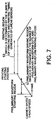
- FIG. 7 is an illustration of the motion in FIG. 1 to FIG. 3.
-
- Next, the preferred embodiments in accordance with the present invention will be described with reference to the drawings. FIG. 1 is a block diagram showing one preferred embodiment of an ink jet printer in accordance with the present invention. As shown in FIG. 1, the ink jet printer in accordance with the present invention is generally constituted by a
controller 1, acarrier 2, and a carrier moving mechanism including a spacing (SP) motor 3. Thecontroller 1 is constituted by a driving waveform generating circuit 4, a motor controlling unit 5 for driving the SP motor 3, a printing data processing circuit 6 for processing a printing data from an externalpersonal computer 7, a central processing unit ( not shown ), and the like. - The
carrier 2 is mounted with ahead 8 in which a plurality of nozzles are arranged in one line in the direction of the line, alinear sensor 9, and the like. Also, thecarrier 2 can be moved in the predetermined direction by the SP motor 3. Thecarrier 2 is driven by a preliminary driving waveform from the driving waveform generating circuit 4 (hereinafter also referred to simply as a preliminary waveform), or by the input of a printing driving waveform to print a head data from a printing data processing circuit 6 when it performs printing. - The driving waveform generating circuit 4 comprises, as shown in FIG. 2, a linear
signal processing unit 11, a printingstarting position register 14, a preliminary waveformstarting position register 15, atimer 13 connected to them, a group ofswitching timing registers 20 for the preliminary waveform, a group of switchingtiming registers 21 for printing, a group of D/A value registers 22 for the preliminary waveform, a group of D/A value registers 23 for printing, and a drivingwaveform generating circuit 24. The linearsignal processing unit 11 receives linear signals ΦA, ΦB from alinear sensor 9 described below and updates aposition register 12 for designating the present position of thehead 8. the printing starting position register 14 sets the output starting position of the printing driving waveform. The preliminary waveform starting position register 15 sets the output starting position of the preliminary waveform. - The
timer 13 is constituted by amain counter 16 for counting up in synchronism with a system clock, a printingdot number register 17, a preliminary waveform dot number register 18, a preliminarywaveform period register 19, and the like. Themain counter 16 starts counting up when the value of theposition register 12 is equal to the value of the preliminary waveform starting position register 15. Themain counter 16 counts up in a period set in the preliminarywaveform period register 19 and stops counting when the driving motion is completed by the number of dots set in the preliminary waveform dot number register 18. - While the
main counter 16 is operating, thetimer 13 controls the driving waveform generatingcircuit 24 according to the values set in the group of D/A value registers 22 for the preliminary waveform and the group of switchingtiming registers 20 for the preliminary waveform. That is, while the preliminary waveform is being outputted, themain counter 16 repeats counting in a period set in the preliminarywaveform period register 19 and when the output of themain counter 16 is equal to the value of the group of switchingtiming registers 20 for the preliminary waveform, the group of D/A value registers 22 for the preliminary waveform are switched to change the driving waveform. While the printing is being performed, themain counter 16 is cleared by a printing trigger signal and while the printing is not performed, themain counter 16 operates similarly while the preliminary waveform is being outputted. - FIG. 3 shows one preferred embodiment of a circuit system diagram of a main part in FIG. 2. In this connection, in FIG. 3, the like reference characters are attached to the like parts in FIG. 2 and the description for them will be omitted. In FIG. 3, the circuit of the main part comprises a preliminary
waveform register unit 30 including the group of switchingtiming registers 20. The group of switchingtiming registers 20 has six switching timing registers each of which has each of values T1 to T6, a group ofAND circuits 26 each of which is provided at the output side of eachswitching timing register 20, aninput OR circuit 27, acounter 28, the group of D/A value registers 22 having six D/A value registers each of which has each of values D1 to D6, and aselector 29; a printing drivingwaveform register unit 31 having the same constitution as the preliminarywaveform register unit 30; and aselector 32. - On the other hand, the
linear sensor 9 shown in FIG. 1 has a well-known constitution and, for example, includes alinear scale 35 in which light-passing portions and light-not-passing portions are alternately arranged in a predetermined period, alight emitting part 36, and alight receiving part 37. In thelinear sensor 9, thelinear scale 35 is arranged such that it crosses the optical path starting from thelight emitting part 36 to thelight receiving part 37. Thelinear sensor 9 outputs a linear signal ΦA obtained by thelight receiving part 37 and a linear signal ΦB whose phase is shifted 90 degrees with respect to the linear signal ΦA, respectively. The periods of the linear signal ΦA and ΦB are inversely proportional to the moving speed of thelinear sensor 9. - In this manner, the periods of the linear signals ΦA and ΦB of the
linear scale 35 are gradually shortened in the range shown by I in FIG. 4B in which thelinear scale 35 is accelerated in the right direction in FIG. 4A with respect to thelight emitting part 36 and thelight receiving part 37, and are gradually elongated in the range II in which thelinear scale 35 is decelerated, and are not changed to be kept constant in the range III in which thelinear scale 35 is stopped. In the range IV in which thelinear scale 35 is accelerated in the left direction, the periods of the linear signals ΦA and ΦB of thelinear scale 35 are gradually elongated and the linear signals ΦA and ΦB of thelinear scale 35 are different in the phase IV from those in the range I. Also, when thelinear scale 35 is moved at constant speed, the linear signals ΦA and ΦB are kept constant in period and in phase, as shown in the range V in FIG. 4B. - If the
light emitting part 36 and thelight receiving part 37 are moved with thecarrier 2 with thelinear scale 35 held fixed and the number of pulses of one of the linear signals ΦA and ΦB is counted, it is possible to specify the relative positions of thelinear sensor 9 and thehead 8 from the initial position. Also, it is possible to find the direction in which thelinear sensor 9 is moved by detecting the phase relationship between the linear signal ΦA and the linear signal ΦB. - Next, the motion of one preferred embodiment shown in FIG. 1 and FIG. 2 will be described in detail with reference to FIG. 3, FIG. 5 to FIG. 7. The linear
signal processing unit 11 in FIG. 2 receives the linear signals ΦA and ΦB outputted from thelinear sensor 9 in FIG. 1. The linearsignal processing unit 11 sets and updates the value of showing the absolute position of thehead 8 in the position register 12 and generates a printing trigger signal when printing is performed. Then, the linearsignal processing unit 11 to supplies the printing trigger signal to themain counter 16 of thetimer 13 as a reset signal. - In the above preferred embodiment, the preliminary waveform driving motion is performed just before a usual printing is performed. That is, the driving waveform generating circuit 4 always compares the position data from the position register 12 showing the present position of the
head 8 with the position data set in the preliminary waveformstarting position register 15, based on the linear signal ΦA and ΦB. When both the position data agree with each other, the driving waveform generating circuit 4 judges that thehead 8 is at the preliminary waveform starting position to make the system clock of themain counter 16 start counting up. - The
main counter 16 circulates the counting values in a period set in the preliminarywaveform period register 19. This motion is repeated by the number of the preliminary waveform dots set in the preliminary waveform dot number register 18. That is, a preliminary waveform driving region is determined by the number of preliminary waveform dots and the preliminary waveform period. The counter value of themain counter 16 is supplied to the group of ANDcircuits 26 in FIG. 3. Every time the counter value reaches any of the values T1 to T6 stored in the group of switching timing registers 20, the output of theOR circuit 27 is applied to thecounter 28 through one corresponding AND circuit among the group of ANDcircuits 26 and theOR circuit 27, whereby the counting-up motion is performed. - Here, the above values T1 to T6 are set in the relationship of T1< T2 < T3 < T4 < T5 < T6. Also, if the maximum of the counter value in one period of the preliminary waveform is between T4 and T5, the
counter 28 counts up every time the counter value of themain counter 16 reaches T1, T2, T3, and T4. The output of thecounter 28 is supplied to theselector 29 in FIG. 3 to make theselector 29 select the D/A value inputted by the group of D/A value registers 22. - The
selector 29 selects the D/A value of D1 based on the output of thecounter 28 until the counter value of themain counter 16 reaches T1. In the same way, theselector 29 selects D2 until the counter value of themain counter 16 reaches T2, D3 until the counter value of themain counter 16 reaches T3, D4 until the counter value of themain counter 16 reaches T4, and D5 until the counter value of themain counter 16 reaches the maximum value. Accordingly, if the counter values of themain counter 16 are those shown in FIG. 5A, the D/A values shown in FIG. 5B are outputted by theselector 29. - The D/A values are supplied to the driving
waveform generating circuit 24 shown in FIG. 2 via theselector 29 shown in FIG. 3. The drivingwaveform generating circuit 24 is constituted in such a way that it outputs a waveform corresponding to the inputted D/A values. The drivingwaveform generating circuit 24 generates a preliminary waveform (shown in FIG. 5C and by areference number 41 in FIG. 6) when the D/A values shown in FIG. 5B are inputted thereto. This preliminary waveform is supplied to thehead 8 by the driving waveform generating circuit 4 shown in FIG. 1. - The preliminary waveform is set at the level in which the ink is swayed to the extent where the ink is not discharged from the opening of the nozzle of the
head 8, which results in reducing the viscosity of the ink. That is, it is determined by the level of the driving waveform applied to the head 8 (that is, the preliminary waveform and the printing driving waveform) whether or not the ink is discharged from the opening of the nozzle of thehead 8. This ink discharging mechanism is well known and its detailed description will be omitted. - In the present preferred embodiment, this preliminary waveform driving region is the range in the state where the
head 8 is accelerated to the state of a constant speed after it reaches the printing starting position from the state of stop to perform the printing, as shown by thereference number 51 in FIG. 7. In this manner, the preliminary waveform period register 19 and the preliminary waveform dot number register 18 are set at suitable values such that the preliminarywaveform driving region 51 finishes before thehead 8 reaches the printing starting position. Just after the preliminarywaveform driving region 51 finishes, thehead 8 reaches the printing starting position, as shown in FIG. 7, thehead 8 thereafter performs the usual printing in theprinting region 52. - The linear
signal processing unit 11 in the driving waveform generating circuit 4 always compares the position data from the position register 12 designating the present position of thehead 8 with the position data set in the printing starting position register 14 in FIG. 2, based on the linear signals ΦA and ΦB. When both the position data agree with each other, the linearsignal processing unit 11 judges that thehead 8 reaches the printing starting position to generate a printing trigger signal shown in FIG. 5D. When the printing trigger signal is supplied to thetimer 13, the system clock of themain counter 16 starts counting up. Further, when the selector signal is generated, theselector 32 shown in FIG. 3 is switched such that it selects the output of the printing drivingwaveform register unit 31. - The
main counter 16 is reset every time the printing trigger signal is inputted. When the driving motion of the number of dots set in the printingdot number register 17 is finished, the circuit stops all the motions. The counter value of themain counter 16 when the usual printing is performed increase, to take the values of T1 to T6 in sequence, as shown in FIG. 5E, until the printing trigger signal is inputted and is reset by the printing trigger signal. - In this way, the D/A values shown in FIG. 5F are taken out of the group of D/A registers 23 for printing in the printing driving
waveform register unit 31 in FIG. 3 via theselector 32. The D/A values taken out of the group of D/A registers 23 for printing are supplied to the drivingwaveform generating circuit 24. The drivingwaveform generating circuit 24 generates a printing driving waveform corresponding to the inputted D/A values (shown in FIG. 5G and by areference number 42 in FIG. 6). When the generated printing driving waveform is outputted to thehead 8, thehead 8 discharges ink from the nozzle to perform the usual printing. - As shown in FIG. 7, the
head 8 reaches a predetermined speed just before it reaches the printing starting position and moves at constant speed in aprinting region 52. Theprinting region 52 is determined by the number of printing dots in the printingdot number register 17 and the printing timing signal generated by thelinear sensor 9. - In this way, in the present preferred embodiment, as is understood from FIG. 7, the preliminary
waveform driving region 51 is made in the period in which thehead 8 is accelerated just after the head 8 (carrier 2) starts moving for printing until it reaches the printing starting position, and the preliminary waveform generated in the preliminarywaveform driving region 51 sways the ink in the opening of the nozzle of thehead 8 to the extent where the ink is not discharged to reduce the viscosity of the ink and the printing is performed in theusual printing region 52 immediately after thehead 8 passes the preliminarywaveform driving region 51. Accordingly, this can drive thehead 8 for printing before the viscosity of the ink, which is reduced by the preliminary driving motion, is increased and can easily discharge the ink from the nozzle when thehead 8 performs the printing. - Also, in the present preferred embodiment, in the preliminary
waveform driving region 51 is produced only the motion of swaying the ink in the opening of the nozzle of thehead 8 to the extent where the ink is not discharged. Accordingly, it is not required to produce such a following complex motion as is required in the ink jet printer of the above-mentioned third conventional technology: that is, in the case where a plurality of nozzles are divided into groups of a predetermined number of nozzles and each of the divided groups of nozzles is filled with the ink of different color, in order to prevent the inks of different colors from being mixed, a preliminary driving motion is performed in which each ink is discharged in a different number of dischargings according to the color of the ink and the discharging motions of the inks of the plurality of colors are finished at the same time. - Therefore, it is possible to realize the preliminary driving motion by a simple constitution and to prevent the useless consumption of the ink when the preliminary driving motion is performed.
- As described above, in the present invention, the preliminary waveform driving region is made in the period in which the head moves just after the head starts morning for printing until it reaches the printing starting position, and the preliminary waveform generated in the preliminary waveform driving region sways the ink in the opening of the nozzle of the head to the extent where the ink is not discharged to reduce the viscosity of the ink and the printing is performed in the usual printing region immediately after the head passes the preliminary waveform driving region. Accordingly, this can drive the head for printing before the viscosity of the ink, which is reduced by the preliminary driving motion, is increased and can easily discharge the ink from the nozzle when the head performs the printing. As a result, the drops of the ink discharged from all nozzles are made identical in speed and direction to improve the quality of the image (printing).
- Also, the present invention only sways the ink in the opening of the nozzle of the head to the extent that the ink is not discharged in the preliminary waveform driving region. Accordingly, it is not required to produce such a following complex motion as is required in the ink jet printer of the above-mentioned third conventional technology: that is, in the case where a plurality of nozzles are divided into groups of a predetermined number of nozzles and each of the divided groups of nozzles is filled with the ink of different color, in order to prevent the inks of different colors from being mixed with each other, the preliminary driving motion is performed in which each ink is discharged a different number of dischargings according to the color of the ink and the discharging motions of the inks of the plurality of colors are finished at the same time. Therefore, it is possible to realize the preliminary driving motion by a simple constitution and to prevent the useless consumption of the ink when the preliminary driving motion is performed.
- While the present invention has been described in connection with a preferred embodiment thereof, it will be understood that it is not intended to limit the invention to that embodiment. On the other hand, it is intended to cover alternatives, modifications, and equivalents as may be included within the spirit and scope of the invention as defined by the following appended claims.
Claims (8)
- An ink jet printer for performing printing by discharging ink from a plurality of nozzles mounted on a head moving with a carrier, the ink jet printer comprising:a position detecting device for detecting the present position of the head;a preliminary waveform generating device for comparing the output of the position detecting device with a preliminary waveform starting position which is previously set to detect that the head reaches the preliminary waveform a starting position and for generating a preliminary waveform during a preliminary waveform driving region previously set, in the period in which the head moves from the position where it is detected that the head reaches the preliminary waveform starting position to a printing starting position; anda printing driving waveform generating device for comparing the output of the position detecting device with the printing starting position previously set just after the preliminary waveform driving region to detect that the head reaches the printing starting position and for generating a printing driving waveform during a printing region previously set after the time when it is detected that the head reaches the printing starting position, and
wherein the preliminary waveform sways ink in the opening of the nozzle of the head to the extent that the ink is not discharged from the opening of the nozzle of the head and wherein the printing driving waveform discharges the ink from the opening of the nozzle of the head. - An ink jet printer as claimed in the claim 1, wherein the position detecting device comprises:a linear sensor moving with the carrier, anda linear signal processing unit for processing the output linear signal of the linear sensor.
- An ink jet printer as claimed in claim 1 or 2, wherein the preliminary waveform generating device comprises:a preliminary waveform starting position register for holding the data of the preliminary waveform starting position,a group of D/A value registers for the preliminary waveform for holding D/A values for the preliminary waveform, anda timer for comparing the output of the position detecting device with the output data of the preliminary waveform starting position register to output the D/A value for the preliminary waveform among the group of D/A value registers for the preliminary waveform during a preliminary waveform driving region previously set after the output of the position detecting device agrees with the output data of the preliminary waveform starting position register, and
wherein the printing driving waveform generating device comprises:a printing starting position register for holding the data of the printing starting position,a group of D/A value registers for printing which bold D/A value for printing, anda printing trigger signal generating device for comparing the output of the position detecting device with the output data of the printing starting position register and for generating a printing trigger signal when both of them agree with each other to supply the printing trigger signal to the timer and for switching and outputting the D/A value for printing among the group of D/A value registers for printing from the timer during the printing region previously set, and
wherein a driving waveform generating circuit which generates the preliminary waveform or the printing driving waveform is shared between the preliminary waveform generating device and the printing driving waveform generating device. - An ink jet printer as claimed in the claim 3, wherein:the driving waveform generating circuit always compares the position data from the linear signal processing unit for designating the present position of the head with the position data set in the preliminary waveform starting position register on the basis of the linear signals from the linear sensor and judges that the head reaches the preliminary waveform starting position when both the position data agree with each other to make the system clock of a main counter in the timer start counting up,the main counter circulating a count value by the predetermined number of preliminary waveform dots in a period set by the timer,the main counter counting up every time the counter value of the main counter reaches a predetermined time.
- An ink jet printer as claimed in the claim 4, wherein:the driving waveform generating circuit is adapted to output a preliminary waveform corresponding to the D/A value for the preliminary waveform, the preliminary waveform being supplied to the head.
- An ink jet printer as claimed in the claim 5, wherein:the preliminary waveform is set at the level where the ink is swayed to the extent in which the ink is not discharged from the opening of the nozzle of the head.
- A method of preliminarily driving an ink jet printer, in which the head of the ink jet printer is preliminarily driven just before performing printing by discharging ink from a plurality of nozzles mounted on the head moving with a carrier, the method comprising the steps of:a first step of detecting that the head starts moving to perform printing and reaches a preliminary waveform starting position previously set;a second step of generating a preliminary waveform during a preliminary waveform driving region previously set in the period in which the head moves from the position where it is detected that the head reaches the preliminary waveform starting position to a printing starting position; anda third step of swaying the ink in the head by the preliminary waveform to the extent in which the ink is not discharged from the opening of the nozzle of the head.
- A method of preliminarily driving an ink jet printer as claimed in the claim 7, wherein:a printing driving waveform is inputted to the head, instead of the preliminary waveform, when the head reaches the printing starting position after the head passes the preliminary waveform driving region and the head starts printing based on the printing driving waveform.
Applications Claiming Priority (2)
| Application Number | Priority Date | Filing Date | Title |
|---|---|---|---|
| JP29844699 | 1999-10-20 | ||
| JP29844699A JP2001113728A (en) | 1999-10-20 | 1999-10-20 | Ink-jet printer and its method for preparatory driving |
Publications (3)
| Publication Number | Publication Date |
|---|---|
| EP1093929A2 true EP1093929A2 (en) | 2001-04-25 |
| EP1093929A3 EP1093929A3 (en) | 2001-10-04 |
| EP1093929B1 EP1093929B1 (en) | 2006-02-22 |
Family
ID=17859827
Family Applications (1)
| Application Number | Title | Priority Date | Filing Date |
|---|---|---|---|
| EP00122312A Expired - Lifetime EP1093929B1 (en) | 1999-10-20 | 2000-10-20 | Ink jet printer and its preliminary driving method |
Country Status (5)
| Country | Link |
|---|---|
| US (1) | US6481815B1 (en) |
| EP (1) | EP1093929B1 (en) |
| JP (1) | JP2001113728A (en) |
| CN (1) | CN1294052A (en) |
| DE (1) | DE60026099T2 (en) |
Cited By (2)
| Publication number | Priority date | Publication date | Assignee | Title |
|---|---|---|---|---|
| US7585123B2 (en) | 2001-08-22 | 2009-09-08 | Brother Kogyo Kabushiki Kaisha | Image forming apparatus |
| US7591518B2 (en) | 2001-08-22 | 2009-09-22 | Brother Kogyo Kabushiki Kaisha | Image forming apparatus |
Families Citing this family (6)
| Publication number | Priority date | Publication date | Assignee | Title |
|---|---|---|---|---|
| JP4785306B2 (en) * | 2001-09-17 | 2011-10-05 | キヤノン株式会社 | Ink jet recording apparatus and ink temperature control method in the apparatus |
| JP2009154328A (en) * | 2007-12-25 | 2009-07-16 | Fuji Xerox Co Ltd | Liquid droplet discharge head and image forming apparatus equipped with the same |
| CN107139590B (en) * | 2017-05-05 | 2018-10-30 | 京东方科技集团股份有限公司 | A kind of ink jet printing device and inkjet printing methods |
| WO2019171924A1 (en) * | 2018-03-05 | 2019-09-12 | 株式会社シンク・ラボラトリー | System and method for detecting amount of ink used by inkjet printer and inkjet printer |
| CN113752700B (en) * | 2020-06-03 | 2022-12-09 | 深圳市汉森软件有限公司 | Dynamic switching method, device, equipment and medium for voltage driving waveform of spray head |
| CN115476588B (en) * | 2021-05-31 | 2024-04-23 | 森大(深圳)技术有限公司 | Method, device, equipment and storage medium for optimizing spray head driving waveform |
Citations (3)
| Publication number | Priority date | Publication date | Assignee | Title |
|---|---|---|---|---|
| JPS6438246A (en) | 1987-07-23 | 1989-02-08 | Hewlett Packard Yokogawa | Thermal ink jet printer control system |
| JPH0852885A (en) | 1994-08-12 | 1996-02-27 | Fuji Xerox Co Ltd | Ink jet recording apparatus and preparatory emitting method |
| JPH09164694A (en) | 1995-12-15 | 1997-06-24 | Matsushita Electric Ind Co Ltd | Ink jet printer and its printing method |
Family Cites Families (13)
| Publication number | Priority date | Publication date | Assignee | Title |
|---|---|---|---|---|
| US5107276A (en) | 1989-07-03 | 1992-04-21 | Xerox Corporation | Thermal ink jet printhead with constant operating temperature |
| JPH03190747A (en) | 1989-12-20 | 1991-08-20 | Seiko Epson Corp | Ink jet recording apparatus |
| JP3190747B2 (en) | 1992-10-16 | 2001-07-23 | 昭和電線電纜株式会社 | Insulation stopper |
| JPH08197744A (en) | 1995-01-27 | 1996-08-06 | Copyer Co Ltd | Printer |
| EP0782924B1 (en) | 1995-07-20 | 2002-10-16 | Seiko Epson Corporation | Method and apparatus for ink jet recording |
| JP3496700B2 (en) | 1996-02-22 | 2004-02-16 | セイコーエプソン株式会社 | Ink jet recording apparatus and ink jet recording method |
| EP1174266B1 (en) | 1996-01-29 | 2006-11-22 | Seiko Epson Corporation | Ink-jet recording head |
| JP3556794B2 (en) | 1997-03-11 | 2004-08-25 | コニカミノルタホールディングス株式会社 | Inkjet printer |
| JPH10309810A (en) | 1997-05-12 | 1998-11-24 | Matsushita Electric Ind Co Ltd | Ink-jet recording apparatus |
| JPH1158779A (en) | 1997-08-19 | 1999-03-02 | Ricoh Co Ltd | Ink jet recorder |
| US6270180B1 (en) | 1997-09-08 | 2001-08-07 | Konica Corporation | Ink jet printer |
| EP1024000B1 (en) | 1999-01-29 | 2006-11-02 | Seiko Epson Corporation | Controlling unit and use of an ink-jet recording apparatus |
| JP2000255056A (en) | 1999-03-10 | 2000-09-19 | Seiko Epson Corp | Method for controlling ink-jet recording apparatus |
-
1999
- 1999-10-20 JP JP29844699A patent/JP2001113728A/en active Pending
-
2000
- 2000-10-19 US US09/692,643 patent/US6481815B1/en not_active Expired - Fee Related
- 2000-10-20 DE DE60026099T patent/DE60026099T2/en not_active Expired - Lifetime
- 2000-10-20 CN CN00130015.6A patent/CN1294052A/en active Pending
- 2000-10-20 EP EP00122312A patent/EP1093929B1/en not_active Expired - Lifetime
Patent Citations (3)
| Publication number | Priority date | Publication date | Assignee | Title |
|---|---|---|---|---|
| JPS6438246A (en) | 1987-07-23 | 1989-02-08 | Hewlett Packard Yokogawa | Thermal ink jet printer control system |
| JPH0852885A (en) | 1994-08-12 | 1996-02-27 | Fuji Xerox Co Ltd | Ink jet recording apparatus and preparatory emitting method |
| JPH09164694A (en) | 1995-12-15 | 1997-06-24 | Matsushita Electric Ind Co Ltd | Ink jet printer and its printing method |
Cited By (5)
| Publication number | Priority date | Publication date | Assignee | Title |
|---|---|---|---|---|
| US7585123B2 (en) | 2001-08-22 | 2009-09-08 | Brother Kogyo Kabushiki Kaisha | Image forming apparatus |
| US7591518B2 (en) | 2001-08-22 | 2009-09-22 | Brother Kogyo Kabushiki Kaisha | Image forming apparatus |
| EP1970207A3 (en) * | 2001-08-22 | 2009-10-07 | Brother Kogyo Kabushiki Kaisha | Image forming device |
| EP2269831A1 (en) * | 2001-08-22 | 2011-01-05 | Brother Kogyo Kabushiki Kaisha | Image forming device |
| US8348403B2 (en) | 2001-08-22 | 2013-01-08 | Brother Kogyo Kabushiki Kaisha | Image forming apparatus |
Also Published As
| Publication number | Publication date |
|---|---|
| DE60026099T2 (en) | 2006-08-10 |
| EP1093929B1 (en) | 2006-02-22 |
| CN1294052A (en) | 2001-05-09 |
| JP2001113728A (en) | 2001-04-24 |
| US6481815B1 (en) | 2002-11-19 |
| EP1093929A3 (en) | 2001-10-04 |
| DE60026099D1 (en) | 2006-04-27 |
Similar Documents
| Publication | Publication Date | Title |
|---|---|---|
| US4554556A (en) | Color plotter | |
| EP1905604B1 (en) | Printing apparatus | |
| US6481815B1 (en) | Ink jet printer and its preliminary driving method | |
| KR100438705B1 (en) | Method and inkjet printer for reducing maximum driving current of ink cartridge | |
| JPH05294015A (en) | Ink jet printer | |
| US6174037B1 (en) | Multiple pass ink jet printer with optimized power supply | |
| US8459764B2 (en) | Printing apparatus and printing method | |
| US7726758B2 (en) | Composite printhead fire signals | |
| JP2001253096A (en) | Print using ink of different coloring materials | |
| US7862145B2 (en) | Printing apparatus and method of controlling the same | |
| US7036902B2 (en) | Printing apparatus | |
| JP3728618B2 (en) | Inkjet printer | |
| US6761424B2 (en) | Image print apparatus and control method thereof | |
| JPH0640042A (en) | Device and method for ink jet recording | |
| JP2004306564A (en) | Substrate for recording head, recording head, temperature control method for recording head, and recording device | |
| KR100234434B1 (en) | Nozzle driving circuit of ink jet printer | |
| US8764147B2 (en) | Inkjet printhead and printing apparatus | |
| JP3397388B2 (en) | Recording device | |
| EP1219450B1 (en) | Printing apparatus and method | |
| JP3293707B2 (en) | Ink jet recording device | |
| JPH0852885A (en) | Ink jet recording apparatus and preparatory emitting method | |
| JP2009226691A (en) | Printer and printing method | |
| KR100489182B1 (en) | How to adjust factor of inkjet printer | |
| JP2005349639A (en) | Printer and printing method | |
| JP3167433B2 (en) | Inkjet printer |
Legal Events
| Date | Code | Title | Description |
|---|---|---|---|
| PUAI | Public reference made under article 153(3) epc to a published international application that has entered the european phase |
Free format text: ORIGINAL CODE: 0009012 |
|
| AK | Designated contracting states |
Kind code of ref document: A2 Designated state(s): DE IT Kind code of ref document: A2 Designated state(s): AT BE CH CY DE DK ES FI FR GB GR IE IT LI LU MC NL PT SE |
|
| AX | Request for extension of the european patent |
Free format text: AL;LT;LV;MK;RO;SI |
|
| PUAL | Search report despatched |
Free format text: ORIGINAL CODE: 0009013 |
|
| AK | Designated contracting states |
Kind code of ref document: A3 Designated state(s): AT BE CH CY DE DK ES FI FR GB GR IE IT LI LU MC NL PT SE |
|
| AX | Request for extension of the european patent |
Free format text: AL;LT;LV;MK;RO;SI |
|
| RIC1 | Information provided on ipc code assigned before grant |
Free format text: 7B 41J 19/20 A, 7B 41J 2/05 B |
|
| 17P | Request for examination filed |
Effective date: 20010823 |
|
| AKX | Designation fees paid |
Free format text: DE IT |
|
| RAP1 | Party data changed (applicant data changed or rights of an application transferred) |
Owner name: FUJI XEROX CO., LTD. |
|
| 17Q | First examination report despatched |
Effective date: 20050301 |
|
| GRAP | Despatch of communication of intention to grant a patent |
Free format text: ORIGINAL CODE: EPIDOSNIGR1 |
|
| GRAS | Grant fee paid |
Free format text: ORIGINAL CODE: EPIDOSNIGR3 |
|
| GRAA | (expected) grant |
Free format text: ORIGINAL CODE: 0009210 |
|
| AK | Designated contracting states |
Kind code of ref document: B1 Designated state(s): DE IT |
|
| PG25 | Lapsed in a contracting state [announced via postgrant information from national office to epo] |
Ref country code: IT Free format text: LAPSE BECAUSE OF FAILURE TO SUBMIT A TRANSLATION OF THE DESCRIPTION OR TO PAY THE FEE WITHIN THE PRESCRIBED TIME-LIMIT;WARNING: LAPSES OF ITALIAN PATENTS WITH EFFECTIVE DATE BEFORE 2007 MAY HAVE OCCURRED AT ANY TIME BEFORE 2007. THE CORRECT EFFECTIVE DATE MAY BE DIFFERENT FROM THE ONE RECORDED. Effective date: 20060222 |
|
| REF | Corresponds to: |
Ref document number: 60026099 Country of ref document: DE Date of ref document: 20060427 Kind code of ref document: P |
|
| PLBE | No opposition filed within time limit |
Free format text: ORIGINAL CODE: 0009261 |
|
| STAA | Information on the status of an ep patent application or granted ep patent |
Free format text: STATUS: NO OPPOSITION FILED WITHIN TIME LIMIT |
|
| 26N | No opposition filed |
Effective date: 20061123 |
|
| PGFP | Annual fee paid to national office [announced via postgrant information from national office to epo] |
Ref country code: DE Payment date: 20131016 Year of fee payment: 14 |
|
| PGFP | Annual fee paid to national office [announced via postgrant information from national office to epo] |
Ref country code: IT Payment date: 20131016 Year of fee payment: 14 |
|
| REG | Reference to a national code |
Ref country code: DE Ref legal event code: R119 Ref document number: 60026099 Country of ref document: DE |
|
| PG25 | Lapsed in a contracting state [announced via postgrant information from national office to epo] |
Ref country code: DE Free format text: LAPSE BECAUSE OF NON-PAYMENT OF DUE FEES Effective date: 20150501 |
|
| PG25 | Lapsed in a contracting state [announced via postgrant information from national office to epo] |
Ref country code: IT Free format text: LAPSE BECAUSE OF NON-PAYMENT OF DUE FEES Effective date: 20141020 |