EP1098456A2 - Closed loop power control for low earth orbit satellite communications system - Google Patents
Closed loop power control for low earth orbit satellite communications system Download PDFInfo
- Publication number
- EP1098456A2 EP1098456A2 EP00309656A EP00309656A EP1098456A2 EP 1098456 A2 EP1098456 A2 EP 1098456A2 EP 00309656 A EP00309656 A EP 00309656A EP 00309656 A EP00309656 A EP 00309656A EP 1098456 A2 EP1098456 A2 EP 1098456A2
- Authority
- EP
- European Patent Office
- Prior art keywords
- satellite
- user terminal
- ground station
- user
- gateway
- Prior art date
- Legal status (The legal status is an assumption and is not a legal conclusion. Google has not performed a legal analysis and makes no representation as to the accuracy of the status listed.)
- Withdrawn
Links
Images


Classifications
-
- H—ELECTRICITY
- H04—ELECTRIC COMMUNICATION TECHNIQUE
- H04B—TRANSMISSION
- H04B7/00—Radio transmission systems, i.e. using radiation field
- H04B7/14—Relay systems
- H04B7/15—Active relay systems
- H04B7/185—Space-based or airborne stations; Stations for satellite systems
- H04B7/1853—Satellite systems for providing telephony service to a mobile station, i.e. mobile satellite service
- H04B7/18539—Arrangements for managing radio, resources, i.e. for establishing or releasing a connection
- H04B7/18543—Arrangements for managing radio, resources, i.e. for establishing or releasing a connection for adaptation of transmission parameters, e.g. power control
-
- H—ELECTRICITY
- H04—ELECTRIC COMMUNICATION TECHNIQUE
- H04W—WIRELESS COMMUNICATION NETWORKS
- H04W52/00—Power management, e.g. TPC [Transmission Power Control], power saving or power classes
- H04W52/04—TPC
- H04W52/06—TPC algorithms
- H04W52/08—Closed loop power control
-
- H—ELECTRICITY
- H04—ELECTRIC COMMUNICATION TECHNIQUE
- H04B—TRANSMISSION
- H04B7/00—Radio transmission systems, i.e. using radiation field
- H04B7/14—Relay systems
- H04B7/15—Active relay systems
- H04B7/185—Space-based or airborne stations; Stations for satellite systems
- H04B7/1853—Satellite systems for providing telephony service to a mobile station, i.e. mobile satellite service
- H04B7/18532—Arrangements for managing transmission, i.e. for transporting data or a signalling message
- H04B7/18534—Arrangements for managing transmission, i.e. for transporting data or a signalling message for enhancing link reliablility, e.g. satellites diversity
-
- H—ELECTRICITY
- H04—ELECTRIC COMMUNICATION TECHNIQUE
- H04W—WIRELESS COMMUNICATION NETWORKS
- H04W52/00—Power management, e.g. TPC [Transmission Power Control], power saving or power classes
- H04W52/04—TPC
- H04W52/18—TPC being performed according to specific parameters
- H04W52/26—TPC being performed according to specific parameters using transmission rate or quality of service QoS [Quality of Service]
-
- H—ELECTRICITY
- H04—ELECTRIC COMMUNICATION TECHNIQUE
- H04W—WIRELESS COMMUNICATION NETWORKS
- H04W84/00—Network topologies
- H04W84/02—Hierarchically pre-organised networks, e.g. paging networks, cellular networks, WLAN [Wireless Local Area Network] or WLL [Wireless Local Loop]
- H04W84/04—Large scale networks; Deep hierarchical networks
- H04W84/06—Airborne or Satellite Networks
-
- Y—GENERAL TAGGING OF NEW TECHNOLOGICAL DEVELOPMENTS; GENERAL TAGGING OF CROSS-SECTIONAL TECHNOLOGIES SPANNING OVER SEVERAL SECTIONS OF THE IPC; TECHNICAL SUBJECTS COVERED BY FORMER USPC CROSS-REFERENCE ART COLLECTIONS [XRACs] AND DIGESTS
- Y02—TECHNOLOGIES OR APPLICATIONS FOR MITIGATION OR ADAPTATION AGAINST CLIMATE CHANGE
- Y02D—CLIMATE CHANGE MITIGATION TECHNOLOGIES IN INFORMATION AND COMMUNICATION TECHNOLOGIES [ICT], I.E. INFORMATION AND COMMUNICATION TECHNOLOGIES AIMING AT THE REDUCTION OF THEIR OWN ENERGY USE
- Y02D30/00—Reducing energy consumption in communication networks
- Y02D30/70—Reducing energy consumption in communication networks in wireless communication networks
Definitions
- This invention relates in general to repeater-based communication systems and, in particular, to satellite-based communications systems having bidirectional communication signal links between one or more satellites and at least one ground station.
- Satellite-based communications systems are well represented in the prior art.
- U.S. Patent No. 5,303,286, which issued on April 12, 1994 to one of the inventors of this patent application, and which is entitled "Wireless Telephone/Satellite Roaming System".
- Low earth orbit satellite systems have been proposed for worldwide for mobile, cellular-like communications. These systems provide an ability to use low cost, hand-held communication devices, or user terminals, for communicating via satellite to parties in remote, rural, suburban and other environments.
- user links to and from one or more satellites may operate on a relatively low frequency, such as a UHF signal.
- the user links are connected by the one or more satellites to ground station-originated feeder links that operate at a higher frequency, e.g., 3 GHz to 40 GHz or more.
- the feeder links are connected to a terrestrial gateway which allows the user to gain access to the public switched telephone network (PSTN), a private network, or some other terrestrial communications facility.
- PSTN public switched telephone network
- private network or some other terrestrial communications facility.
- a further consideration in a wireless communication system is the control of transmission power.
- individual user links may be power controlled by a central site, such as a base station, after link impairment information between the user terminal and the base station is exchanged.
- This technique is generally referred to as user terminal power control.
- a function of this power control is to mitigate fading caused by trees, buildings and other RF-impairing factors within the user link. These impairments have the characteristic of reducing the signal power level to a lower level.
- the user terminal can be commanded to increase its transmitted power.
- the user terminal may be able to request that the central station transmit at a higher power level.
- an increase in transmitted power from the user terminal or from a ground station, such as a gateway, can result in increased power being required for the satellite repeater.
- satellite power is a primary resource to be provided to and partitioned between many users, any increase in the power consumption of the satellite is undesirable.
- an increase in transmission power can have a detrimental impact on the number and duration of calls that can be made before the battery is required to be recharged.
- This invention is directed to a satellite communication system, and a method executed by same, for providing adaptive closed loop power control.
- the method comprises the steps of: measuring a quality of at least one reference signal received by a user terminal, transmitting the measured quality of the reference signal received by the user terminal to the ground station, comparing the measured quality, and adjusting a transmit power of the ground station on the basis of the comparison.
- the reference signal being transmitted by the ground station through the satellite to the user terminal.
- the measured quality is compared with a predetermined reference.
- the transmit power of the ground station is adjusted in response to a difference between the predetermined reference and the measured quality so that a flux density of a downlink beam is substantially constant at the user terminal independent of the location of the user terminal in the beam.
- a satellite communication system that includes at least one satellite and at least one ground station.
- the satellite communication system further includes means for transmitting an uplink reference signal, the satellite comprising a receiver and a transmitter, at least one user terminal and a processor coupled to the ground station.
- the satellite receiver receives the uplink reference signal.
- the satellite transmitter transmits the reference signal as a repeated downlink reference signal.
- the user terminal has a receiver for receiving the reference signal repeated by the satellite.
- the user terminal further has means for measuring a quality of the reference signal received by the user terminal, and also has means for transmitting the measured quality.
- the processor is coupled to the ground station for adjusting a transmit power of the ground station based on the measured quality transmitted by the user terminal.
- the processor is programmed to at least one of adjust the transmit power such that a flux density of a downlink beam from the satellite is substantially constant at the user terminal independent of the location of the user terminal in the beam or adjust the transmit power to compensate for predicted variation in satellite gain and maintain the flux density of the beam above a predetermined threshold at the location of the user terminal.
- the plurality of user terminals include a plurality of types of user terminals
- the method for operating the satellite communication system in accordance with the teachings found herein includes steps of measuring a quality of reference signals received by the user terminals, transmitting the measured quality of the reference signals received by the user terminals to the ground station, comparing the measured quality with a predetermined reference, and adjusting the transmit power of the ground station based on the comparison.
- the reference signals are transmitted by the ground station through the satellite to the user terminals.
- the transmit power of the ground station is preferably adjusted to at least one of provide a predetermined percentage of all user terminals in a given one of the downlink beams with downlink signal quality above a common predetermined threshold, or to provide a predetermined percentage of each type of user terminal in the beam with downlink signal quality above a corresponding predetermined threshold that is set independently for each type of user terminal.
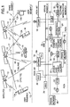
- Fig. 1 illustrates a presently preferred embodiment of a satellite communication system 10 that is suitable for use with the presently preferred embodiment of the adaptive power control function of this invention.
- the communications system 10 may be conceptually sub-divided into a plurality of segments 1, 2, 3 and 4.
- Segment 1 is referred to herein as a space segment, segment 2 as a user segment, segment 3 as a ground (terrestrial) segment, and segment 4 as a telephone system infrastructure segment.
- the presently preferred embodiment of this invention there are a total of 48 satellites in, by example, a 1414 km Low Earth Orbit (LEO).
- the satellites 12 are distributed in eight orbital planes with six equally-spaced satellites per plane (Walker constellation).
- the orbital planes are inclined at 52 degrees with respect to the equator and each satellite completes an orbit once every 114 minutes.
- This approach provides approximately full-earth coverage with, preferably, at least two satellites in view at any given time from a particular user location between about 70 degree south latitude and about 70 degree north latitude.
- a user is enabled to communicate to or from nearly any point on the earth's surface within a gateway (GW) 18 coverage area to or from other points on the earth's surface (by way of the PSTN), via one or more gateways 18 and one or more of the satellites 12, possibly also using a portion of the telephone infrastructure segment 4.
- GW gateway
- system 10 represents but one suitable embodiment of a communication system within which the teaching of this invention may find use. That is, the specific details of the communication system are not to be read or construed in a limiting sense upon the practice of this invention.
- a soft transfer (handoff) process between satellites 12, and also between individual ones of 16 spot beams transmitted by each satellite provides unbroken communications via a spread spectrum (SS), code division multiple access (CDMA) technique.
- SS spread spectrum
- CDMA code division multiple access
- the presently preferred SS-CDMA technique is similar to the TIA/EIA Interim Standard, "Mobile Station-Base Station Compatibility Standard for Dual-Mode Wideband Spread Spectrum Cellular System" TIA/EIA/IS-95, July 1993, although other spread spectrum and CDMA techniques and protocols can be employed.
- the low earth orbits permit low-powered fixed or mobile user terminals 13 to communicate via the satellites 12, each of which functions, in a presently preferred embodiment of this invention, solely as a "bent pipe" repeater to receive a communications traffic signal (such as speech and/or data) from a user terminal 13 or from a gateway 18, convert the received communications traffic signal to another frequency band, and to then re-transmit the converted signal. That is, no on-board signal processing of a received communications traffic signal occurs, and the satellite 12 does not become aware of any intelligence that a received or transmitted communications traffic signal may be conveying.
- a communications traffic signal such as speech and/or data
- each of the satellites 12 receives a signal only from a transmitter located in the user segment 2 or from a transmitter located in the ground segment 3, and transmits a signal only to a receiver located in the user segment 2 or to a receiver located in the ground segment 3.
- the user segment 2 may include a plurality of types of user terminals 13 that are adapted for communication with the satellites 12.
- the user terminals 13 include, by example, a plurality of different types of fixed and mobile user terminals including, but not limited to, handheld mobile radio-telephones 14, vehicle mounted mobile radio-telephones 15, paging/messaging-type devices 16, and fixed radio-telephones 14a.
- the user terminals 13 are preferably provided with omnidirectional antennas 13a for bidirectional communication via one or more of the satellites 12.
- the fixed radio-telephones 14a may employ a directional antenna. This is advantageous in that it enables a reduction in interference with a consequent increase in the number of users that can be simultaneously serviced with one or more of the satellites 12.
- the user terminals 13 may be dual use devices that include circuitry for also communicating in a conventional manner with a terrestrial cellular system.
- the user terminals 13 may be capable of operating in a full duplex mode and communicate via, by example, L-band RF links (uplink or return link 17b) and S-band RF links (downlink or forward link 17a) through return and forward satellite transponders 12a and 12b, respectively.
- the return L band RF links 17b may operate within a frequency range of 1.61 GHz to 1.625 GHz, a bandwidth of 16.5 MHz, and are modulated with packetized digital voice signals and/or data signals in accordance with the preferred spread spectrum technique.
- the forward S band RF links 17a may operate within a frequency range of 2.485 GHz to 2.5 GHz, a bandwidth of 16.5 MHz.
- the forward RF links 17a are also modulated at a gateway 18 with packetized digital voice signals and/or data signals in accordance with the spread spectrum technique.
- the 16.5 MHz bandwidth of the forward link is partitioned into 13 channels with up to, by example, 128 users being assigned per channel.
- the return link may have various bandwidths, and a given user terminal 13 may or may not be assigned a different channel than the channel assigned on the forward link. However, when operating in the diversity reception mode on the return link (receiving from two or more satellites 12), the user is assigned the same forward and return link RF channel for each of the satellites.
- the ground segment 3 includes at least one but generally a plurality of the gateways 18 that communicate with the satellites 12 via, by example, a full duplex C band RF link 19 (forward link 19a (to the satellite), return link 19b (from the satellite)) that operates within a range of frequencies generally above 3 GHz and preferably in the C-band.
- the C-band RF links bi-directionally convey the communication feeder links, and also convey satellite commands to the satellites and telemetry information from the satellites.
- the forward feeder link 19a may operate in the band of 5 GHz to 5.25 GHz
- the return feeder link 19b may operate in the band of 6.875 GHz to 7.075 GHz.
- the satellite feeder link antennas 12g and 12h are preferably wide coverage antennas that subtend a maximum earth coverage area as seen from the LEO satellite 12.
- the angle subtended from a given LEO satellite 12 (assuming 10° elevation angles from the earth's surface) is approximately 110°. This yields a coverage zone that is approximately 3600 miles in diameter.
- the L-band and the S-band antennas are multiple beam antennas that provide coverage within an associated terrestrial service region.
- the L-band and S-band antennas 12d and 12c, respectively, are preferably congruent with one another, as depicted in Fig. 3B. That is, the transmit and receive beams from the spacecraft cover the same area on the earth's surface, although this feature is not critical to the operation of the system 10.
- two or more satellites 12 may each convey the same communication between a given user terminal 13 and one of the gateways 18. This mode of operation, as described in detail below, thus provides for diversity combining at the respective receivers, leading to an increased resistance to fading and facilitating the implementation of a soft handoff procedure.
- the feeder links between the gateways and the satellites may use frequencies in a band other than the C-band (approximately 3 GHz to approximately 7 GHz), for example the Ku band (approximately 10 GHz to approximately 15 GHz) or the Ka band (above approximately 15 GHz).
- the teaching of this invention becomes especially useful.
- the gateways 18 function to couple the communications payload or transponders 12a and 12b (Fig. 3A) of the satellites 12 to the telephone infrastructure segment 4.
- the transponders 12a and 12b include an L-band receive antenna 12c, S-band transmit antenna 12d, C-band power amplifier 12e, C-band low noise amplifier 12f, C-band antennas 12g and 12h, L band to C band frequency conversion section 12i, and C band to S band frequency conversion section 12j.
- the satellite 12 also includes a master frequency generator 12k and command and telemetry equipment 12l.
- the telephone infrastructure segment 4 is comprised of existing telephone systems and includes Public Land Mobile Network (PLMN) gateways 20, local telephone exchanges such as regional public telephone networks (RPTN) 22 or other local telephone service providers, domestic long distance networks 24, international networks 26, private networks 28 and other RPTNs 30.
- PLMN Public Land Mobile Network
- RPTN regional public telephone networks
- the communication system 10 operates to provide bidirectional voice and/or data communication between the user segment 2 and Public Switched Telephone Network (PSTN) telephones 32 and non-PSTN telephones 32 of the telephone infrastructure segment 4, or other user terminals of various types, which may be private networks.
- PSTN Public Switched Telephone Network
- a Satellite Operations Control Center (SOCC) 36 As a portion of the ground segment 3, is a Satellite Operations Control Center (SOCC) 36, and a Ground Operations Control Center (GOCC) 38.
- a communication path which includes a Ground Data Network (GDN) 39 (see Fig. 2), is provided for interconnecting the gateways 18 and TCUs 18a, SOCC 36 and GOCC 38 of the ground segment 3.
- GDN Ground Data Network
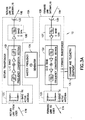
- Fig. 2 shows one of the gateways 18 in greater detail.
- Each gateway 18 includes up to four dual polarization RF C-band sub-systems each comprising a dish antenna 40, antenna driver 42 and pedestal 42a, low noise receivers 44, and high power amplifiers 46. All of these components may be located within a radome structure to provide environmental protection.
- the gateway 18 further includes down converters 48 and up converters 50 for processing the received and transmitted RF carrier signals, respectively.
- the down converters 48 and the up converters 50 are connected to a CDMA sub-system 52 which, in turn, is coupled to the Public Switched Telephone Network (PSTN) though a PSTN interface 54.
- PSTN Public Switched Telephone Network
- the PSTN could be bypassed by using satellite-to-satellite links.
- the CDMA sub-system 52 includes a signal summer/switch unit 52a, a Gateway Transceiver Subsystem (GTS) 52b, a GTS Controller 52c, a CDMA Interconnect Subsystem (CIS) 52d, and a Selector Bank Subsystem (SBS) 52e.
- the CDMA sub-system 52 is controlled by a Base Station Manager (BSM) 52f and functions in a manner similar to a CDMA-compatible (for example, an IS-95 compatible) base station.
- BSM Base Station Manager
- the CDMA sub-system 52 also includes the required frequency synthesizer 52g and a Global Positioning System (GPS) receiver 52h.
- GPS Global Positioning System
- the PSTN interface 54 includes a PSTN Service Switch Point (SSP) 54a, a Call Control Processor (CCP) 54b, a Visitor Location Register (VLR) 54c, and a protocol interface 54d to a Home Location Register (HLR).
- SSP PSTN Service Switch Point
- CCP Call Control Processor
- VLR Visitor Location Register
- HLR Home Location Register
- the HLR may be located in the cellular gateway 20 (Fig. 1) or, optionally, in the PSTN interface 54.
- the gateway 18 is connected to telecommunication networks through a standard interface made through the SSP 54a.
- the gateway 18 provides an interface, and connects to the PSTN via Primary Rate Interface (PRI).
- PRI Primary Rate Interface
- the gateway 18 is further capable of providing a direct connection to a Mobile Switching Center (MSC).
- MSC Mobile Switching Center
- the gateway 18 provides SS-7 ISDN fixed signalling to the CCP 54b.
- the CCP 54b interfaces with the CIS 52d and hence to the CDMA sub-system 52.
- the CCP 54b provides protocol translation functions for the system Air Interface (AI), which may be similar to the IS-95 Interim Standard for CDMA communications.
- AI system Air Interface
- Blocks 54c and 54d generally provide an interface between the gateway 18 and an external cellular telephone network that is compatible, for example, with the IS-41 (North American Standard, AMPS) or the GSM (European Standard, MAP) cellular systems and, in particular, to the specified methods for handling roamers, that is, users who place calls outside of their home system.
- the gateway 18 supports user terminal authentication for system 10/AMPS phones and for system 10/GSM phones.
- an HLR can be added to the gateway 18 and interfaced with the SS-7 signalling interface.
- a user making a call out of the user's normal service area (a roamer) is accommodated by the system 10 if authorized.
- a roamer may be found in any environment, a user may employ the same terminal equipment to make a call from anywhere in the world, and the necessary protocol conversions are made transparently by the gateway 18.
- the protocol interface 54d is bypassed when not required to convert, by example, GSM to AMPS.
- the gateway controller 56 which includes an interface 56a to the above-mentioned Ground Data Network (GDN) 39 and an interface 56b to a Service Provider Control Center (SPCC) 60.
- the gateway controller 56 is generally interconnected to the gateway 18 through the BSM 52f and through RF controllers 43 associated with each of the antennas 40.
- the gateway controller 56 is further coupled to a database 62, such as a database of users, satellite ephemeris data, etc., and to an I/O unit 64 that enables service personnel to gain access to the gateway controller 56.
- the GDN 39 is also bidirectionally interfaced to a Telemetry and Command (T&C) unit 66 (Figs. 1 and 4).
- T&C Telemetry and Command
- the function of the GOCC 38 is to plan and control satellite utilization by the gateways 18, and to coordinate this utilization with the SOCC 36.
- the SOCC 36 operates to maintain and monitor orbits, to relay satellite usage information to the gateway for input to the GOCC 38 via the GDN 39, to monitor the overall functioning of each satellite 12, including the state of the satellite batteries, to set the gain for the RF signal paths within the satellite 12, to ensure optimum satellite orientation with respect to the surface of the earth, in addition to other functions.
- each gateway 18 functions to connect a given user to the PSTN for both signalling, voice and/or data communications and also to generate data, via database 62 (Fig. 2), for billing purposes.
- Selected gateways 18 include a Telemetry and Command Unit (TCU) 18a for receiving telemetry data that is transmitted by the satellites 12 over the return link 19b and for transmitting commands up to the satellites 12 via the forward link 19a.
- TCU Telemetry and Command Unit
- the GDN 39 operates to interconnect the gateways 18, GOCC 38 and the SOCC 36.
- each satellite 12 of the LEO constellation operates to relay information from the gateways 18 to the users (C band forward link 19a to S band forward link 17a), and to relay information from the users to the gateways 18 (L band return link 17b to C band return link 19b).
- This information includes SS-CDMA synchronization and paging channels, in addition to power control signals.
- Various CDMA pilot channels may also be used to monitor interference on the forward link.
- Satellite ephemeris update data is also communicated to each of the user terminals 13, from the gateway 18, via the satellites 12.
- the satellites 12 also function to relay signalling information from the user terminals 13 to the gateway 18, including access requests, power change requests, and registration requests.
- the satellites 12 also relay communication signals between the users and the gateways 18, and may apply security to mitigate unauthorized use.
- the satellites 12 transmit spacecraft telemetry data that includes measurements of satellite operational status.
- the telemetry stream from the satellites, the commands from the SOCC 36, and the communications feeder links 19 all share the C band antennas 12g and 12h.
- the received satellite telemetry data may be forwarded immediately to the SOCC 36, or the telemetry data may be stored and subsequently forwarded to the SOCC 36 at a later time, typically upon SOCC request.
- the telemetry data, whether transmitted immediately or stored and subsequently forwarded, is sent over the GDN 39 as packet messages, each packet message containing a single minor telemetry frame. Should more than one SOCC 36 be providing satellite support, the telemetry data is routed to all of the SOCCs.
- the SOCC 36 has several interface functions with the GOCC 38.
- One interface function is orbit position information, wherein the SOCC 36 provides orbital information to the GOCC 38 such that each gateway 18 can accurately track up to four satellites that may be in view of the gateway.
- This data includes data tables that are sufficient to allow the gateways 18 to develop their own satellite contact lists, using known algorithms.
- the SOCC 36 is not required to known the gateway tracking schedules.
- the TCU 18a searches the downlink telemetry band and uniquely identifies the satellite being tracked by each antenna prior to the propagation of commands.
- satellite status information that is reported from the SOCC 36 to the GOCC 38.
- the satellite status information includes both satellite/transponder availability, battery status and orbital information and incorporates, in general, any satellite-related limitations that would preclude the use of all or a portion of a satellite 12 for communications purposes.
- An important aspect of the system 10 is the use of SS-CDMA in conjunction with diversity combining at the gateway receivers and at the user terminal receivers.
- Diversity combining is employed to mitigate the effects of fading as signals arrive at the user terminals 13 or the gateway 18 from multiple satellites over multiple and different path lengths.
- Rake receivers in the user terminals 13 and the gateways 18 are employed to receive and combine the signals from multiple sources.
- a user terminal 13 or the gateway 18 provides diversity combining for the forward link signals or the return link signals that are simultaneously received from and transmitted through the multiple beams of the satellites 12.
- the multiple, directional, antennas 40 of a given one of the gateways 18 are capable of transmitting the forward link signal (gateway to user terminal) through different beams of one or more satellites 12 to support diversity combining in the user terminals 13.
- the omnidirectional antennas 13a of the user terminals 13 transmit through all satellite beams that can be "seen" from the user terminal 13.
- Each gateway 18 supports a transmitter power control function to address slow fades, and also supports block interleaving to address medium to fast fades. Power control is implemented on both the forward and reverse links. The response time of the power control function is adjusted to accommodate for a worst case 30 msec satellite round trip delay.
- the block interleavers (53d, 53e, 53f, Fig. 5) operate over a block length that is related to vocoder 53g packet frames.
- An optimum interleaver length trades off a longer length, and hence improved error correction, at the expense of increasing the overall end-to-end delay.
- a preferred maximum end-to-end delay is 150 msec or less. This delay includes all delays including those due to the received signal alignment performed by the diversity combiners, vocoder 53g processing delays, block interleaver 53d-53f delays, and the delays of the Viterbi decoders (not shown) that form a portion of the CDMA sub-system 52.
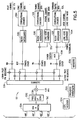
- Fig. 5 is a block diagram of the forward link modulation portion of the CDMA sub-system 52 of Fig. 2.
- An output of a summer block 53a feeds a frequency agile up-converter 53b which in turn feeds the summer and switch block 52a.
- the telemetry and control (T&C) information is also input to the block 52a.
- An unmodulated direct sequence SS pilot channel generates an all zeros Walsh Code at a desired bit rate.
- This data stream is combined with a short PN code that is used to separate signals from different gateways 18 and different satellites 12. If used, the pilot channel is modulo 2 added to the short code and is then QPSK or BPSK spread across the CDMA FD RF channel bandwidth.
- the following different pseudonoise (PN) code offsets are provided: (a) a PN code offset to allow a user terminal 13 to uniquely identify a gateway 18; (b) a PN code offset to allow the user terminal 13 to uniquely identify a satellite 12; and (c) a PN code offset to allow the user terminal 13 to uniquely identify a given one of the 16 beams that is transmitted from the satellite 12. Pilot PN codes from different ones of the satellites 12 are assigned different time/phase offsets from the same pilot seed PN code.
- each pilot channel that is transmitted by the gateway 18 may be transmitted at a higher or lower power level than the other signals.
- a pilot channel enables a user terminal 13 to acquire the timing of the forward CDMA channel, provides a phase reference for coherent demodulation, and provides a mechanism to perform signal strength comparisons to determine when to initiate handoff.
- the use of the pilot channel is not, however, mandatory, and other techniques can be employed for this purpose.
- the Sync channel generates a data stream that includes the following information: (a) time of day; (b) transmitting gateway identification; (c) satellite ephemeris; and (d) assigned paging channel.
- the Sync data is applied to a convolution encoder 53h where the data is convolutionally encoded and subsequently block interleaved to combat fast fades.
- the resulting data stream is modulo two added to the synchronous Walsh code and QPSK or BPSK spread across the CDMA FD RF channel bandwidth.
- the Paging channel is applied to a convolutional encoder 53i where it is convolutionally encoded and is then block interleaved.
- the resulting data stream is combined with the output of a long code generator 53j.
- the long PN code is used to separate different user terminal 13 bands.
- the paging channel and the long code are modulo two added and provided to a symbol cover where the resulting signal is modulo two added to the Walsh Code.
- the result is then QPSK or BPSK spread across the CDMA FD RF channel bandwidth.
- the paging channel conveys several message types which include: (a) a system parameter message; (b) an access parameter message; and (c) a CDMA channel list message.
- the system parameter message includes the configuration of the paging channel, registration parameters, and parameters to aid in acquisition.
- the access parameters message includes the configuration of the access channel and the access channel data rate.
- the CDMA channel list message conveys, if used, an associated pilot identification and Walsh code assignment.
- the vocoder 53k encodes the voice into a PCM forward traffic data stream.
- the forward traffic data stream is applied to a convolutional encoder 53l where it is convolutionally encoded and then block interleaved in block 53f.
- the resulting data stream is combined with the output of a user long code block 53k.
- the user long code is employed to separate different subscriber channels.
- the resulting data stream is then power controlled in multiplexer (MUX) 53m, modulo two added to the Walsh code, and then QPSK or BPSK spread across the CDMA FD RF communication channel bandwidth.
- MUX multiplexer
- the gateway 18 operates to demodulate the CDMA return link(s).
- the gateway 18 receives and decodes a burst on the access channel that requests access.
- the access channel message is embodied in a long preamble followed by a relatively small amount of data.
- the preamble is the user terminal's long PN code.
- Each user terminal 13 has a unique long PN code generated by a unique time offset into the common PN generator polynomial.
- the gateway 18 After receiving the access request, the gateway 18 sends a message on the forward link paging channel (blocks 53e, 53i, 53j) acknowledging receipt of the access request and assigning a Walsh code to the user terminal 13 to establish a traffic channel.
- the gateway 18 also assigns a frequency channel to the user terminal 13. Both the user terminal 13 and the gateway 18 switch to the assigned channel element and begin duplex communications using the assigned Walsh (spreading) code(s).
- the return traffic channel is generated in the user terminal 13 by convolutionally encoding the digital data from the local data source or the user terminal vocoder.
- the data is then block interleaved at predetermined intervals and is applied to a 128-Ary modulator and a data burst randomizer to reduce clashing.
- the data is then added to the zero offset PN code and transmitted through one or more of the satellites 12 to the gateway 18.
- the gateway 18 processes the return link by using, by example, a Fast Hadamard Transform (FHT) to demodulate the 128-Ary Walsh Code and provide the demodulated information to the diversity combiner.
- FHT Fast Hadamard Transform
- the forward link is considered as the link from the gateway 18 to the user terminals 13 via at least one satellite 12.
- the feeder link 19 is considered to be that portion of the forward link which connects the satellite 12 to and from the gateway 18, while the user links 17 are considered to be that portion of the forward link from which connects the satellite 12 to and from the user terminals 13.
- the feeder link to one or more satellites 12 from the gateway 18 provides the drive power for the user links.
- the user links consume a considerable amount of power on the satellite 12. If there is no impairment on the feeder link, as between the gateway 18 and the satellite 12', the power of the satellite is maximized to its associated user links, thereby maximizing the efficiency and capacity of the total system.
- the user link power control loop described previously will be activated whether or not a particular user terminal 13 finds itself impaired. That is, a user terminal 13 detecting a decrease in the signal power received from the satellite 12'' will send a message over the reverse link requesting that the power of the forward link be increased. It can be appreciated that due to the attenuation in the feeder link signal due to a rain cell that all user terminals 13 receiving communication signals from the satellite 12'' will simultaneously experience a decrease in received power, and will simultaneously request that the feeder link power be increased. The resulting sudden surge in feeder link power translates to a significant corresponding increase in power consumption in the satellite 12'', which operates to repeat the feeder link signals to the user terminals 13 with a power that corresponds in a substantially linear fashion to the received feeder link power.
- low earth orbit satellite systems and other satellite systems generally, track a satellite as it passes over the ground station, in this case the gateway 18.
- the gateway 18 antenna 40 being steered such that it may be transmitting the feeder link signal F1 through the rain cell.
- the signal level of feeder link portion F2 will be reduced compared to F1.
- the feeder link portion F2 experiences additional path loss until it reaches the satellite 12''. As a result of these losses all user terminals 13 will demand more satellite prime power.
- An outer power control loop is provided in the feeder link(s) at the gateway 18.
- the outer power control loop operates to increase the transmitted power from the gateway 18 antenna 40 in proportion to the attenuation caused by a feeder link impairment, in this case a rain cell.
- This outer power control loop thus maintains the power flux density received by the satellite 12'' at a nearly constant level and, as a result, the user terminals 13 do not experience a significant decrease in received power from the satellite 12''.
- the outer power control loop includes a reference signal receiver 70 and a reference signal tracking processor 72, as shown in Figs. 6 and 7.
- the reference signal receiver 70 and the reference signal tracking processor 72 operate in conjunction with the RF system controllers 43 and feeder link RF systems 46, 50 (as shown in the gateway 18 block diagram of Fig. 2).
- the reference signal receiver 70 monitors a downlink reference (R) signal from the satellites 12 at a specified frequency. This frequency is selected to be low enough so that it is not significantly impaired by the rain cell (for example a frequency in the S-band), and thus remains at essentially the same level at portion R2 as at portion R1.
- the reference signal receiver 70 demodulates the received SS-CDMA signal and outputs as a data stream 70a a reference signal received signal power indication to the reference signal tracking processor 72 in the gateway 18.
- the reference signal tracking processor 72 processes the data stream 70a and issues error signals or commands to the one or more RF system controllers 43, which in turn control the gain of the feeder link RF system(s) 46, 50 on link 1 to link N of the gateway 18. In this manner the transmitted feeder link power is increased in proportion to the amount of attenuation experienced by the feeder link between the gateway 18 and a satellite 12.
- the feeder link spread spectrum reference signal receiver 70 receives and demodulates each of the down link reference signals R. Since the reference signal downlink frequency is significantly less than the uplink feeder link frequency, the majority of the rain loss (if any) is incurred by the uplink feeder link signal. Consequently, at Block B the received signal power indication signal is compared to a predetermined reference by the reference signal tracking processor 72, and at Block C an error signal (E) proportional to the feeder link loss caused by a channel impairment, such as rain, is derived and output to the RF system controllers 43. That is, an error signal (E 1 to E N ) is derived for each of the feeder links 1-N. The error signal in turn is used by each RF system controller 43 to control, at Block D, the power of the composite feeder link that is comprised of the reference signal R, and all of the individual user terminal 13 communication signals, to compensate for the rain loss.
- E error signal proportional to the feeder link loss caused by a channel impairment, such as rain
- the reference signal R is transmitted on the uplink feeder link with a predetermined PN code and a first frequency from gateway 18, is attenuated by RF impairments, such as a rain cell, between the satellite 12'' and the gateway 18, is received and repeated by the satellite 12'' at a second, lower frequency on the downlink, and is received, despread, demodulated and processed by the reference signal receiver 70 and the reference signal tracking processor 72.
- An error signal is next developed that indicates an amount of RF impairment that is occurring on the uplink feeder link, it being remembered that the uplink frequency band causes the feeder link to be more susceptible to RF impairments, such as rain, than the downlink signal from the satellite 12''.
- the error signal is then employed to vary the uplink feeder link transmission power so as to cause the power level of each of the signals received by each of the user terminals 13 to remain substantially the same.
- an error signal can be provided to each of the RF system controllers 43, from which each RF system controller 43 derives a change in its associated feeder link power; or a change in feeder link power can be derived in the reference signal tracking processor 72 from the error signal, for each RF system controller 43, and transmitted as a suitable power control command to the RF system controllers.
- a single reference signal receiver 70 may be utilized to independently control the feeder link uplink powers to each of the satellites 12 within view of a particular gateway 18. That is, a distinct PN code is assigned to each reference signal.
- the reference signal receiver 70 may employ a well-known RAKE receiver having a plurality of fingers for simultaneously despreading and tracking a plurality of the reference signals.
- the reference signal receiver 70 may instead employ a single finger that is time multiplexed between the reference signals repeated by a plurality of satellites 12 that are in view of the reference signal receiver 70. In either case the uplink feeder link power is increased only as necessary, allowing more efficient use of the satellite capacity and minimizing coordination difficulties with other satellites 12 in similar orbits and which share the same band of frequencies. This technique also minimizes the effect of higher feeder link power for terrestrial coordination.
- a plurality of reference signal receivers 70 may be placed at suitable points over the gateway coverage area, and the reference signal data stream is conveyed to the reference signal tracking processor 72 over terrestrial data lines, or as a data stream via the satellites 12. In this latter case the data stream can also be received by the reference signal receiver 70 at the gateway 18 and then input to the reference signal tracking processor 72.
- a received signal power or quality indication that is reported back to the gateway 18 in the data stream 70a may be, by example, a received signal strength indicator (RSSI) measurement, or a signal quality measurement.
- the signal quality indication could be based on, for example, a received bit error rate (BER) measurement, or on a frame error rate (FER) measurement derived from, by example, Viterbi decoder metrics.
- the quality indication could also be based in whole or in part on a subjective Mean Opinion Score wherein predetermined voice sequences are rated by a population of listeners.
- the signal power or quality indication is compared by the reference signal tracking processor 72 to a predetermined value, such as a reference signal strength or signal quality value, and the error signal is developed so as to represent a deviation between the two compared values.
- a predetermined value such as a reference signal strength or signal quality value
- a goal of the outer power control loop is to minimize the feeder link power in a manner that is consistent with the desired link quality. Minimizing the feeder link power, while simultaneously providing satisfactory user communications, thus conserves satellite prime power.
- the reference value to which the received signal power indication is compared is determined in accordance with a desired power level at which the user terminals 13 are to receive the communication signals that are repeated by the satellites 12 from the feeder link.
- the reference value need not be a fixed value, but can be varied depending upon, by example, total user load or demand, time of day, a total desired RF flux level at the ground within a given satellite spot beam (e.g., approximately 154 dBW/m 2 /4 kHz, as a function of elevation angle), etc.
- the gateway 18 may process the inputs from the plurality of reference signal receivers 70 and 70' by combining them in a predetermined manner, such as by an averaging or a weighted averaging technique.
- a predetermined manner such as by an averaging or a weighted averaging technique.
- reference signal power indications received from those reference signal receivers 70' that are associated with a region having a high user density (i.e., urban areas) may be weighted more heavily than signal power indications received from regions with a lower user density.
- the power control technique of this invention thus compensates for impairments in the feeder links (e.g., rain attenuation for Ka or Ku band feeder links, impairments due to a low elevation angle satellite receiving a C-band feeder link, impairments due to signals received from impaired beams, etc.), and may also compensate for a degradation in satellite operational capacity over time.
- impairments in the feeder links e.g., rain attenuation for Ka or Ku band feeder links, impairments due to a low elevation angle satellite receiving a C-band feeder link, impairments due to signals received from impaired beams, etc.
- the closed loop power control technique of this invention may be viewed as a two-level adaptive power control loop 80 with an outer, global feeder link power control loop 82 to compensate for bulk power impairments (e.g., those due to rain cells) and a plurality of inner, user link power control loops 84 to compensate for individual user link impairments (such as those resulting from foliage).
- a time constant of the outer feeder link power control loop 82 is preferably longer (for example, 5 to 10 times longer) than that of the inner user link power control loops 84.
- the gateway 18 compensates all user links for the 8 dB rain cell loss by increasing the feeder link power proportionately, then the dynamic range of the user terminal power control function is not adversely affected by the rain cell-induced loss.
- the outer power control loop allows the gateways 18 to maintain a near-constant, desired flux density on the surface of the earth, compensating for losses in the forward link due to such factors as for example; uplink and downlink attenuation, mispointing of the gateway antenna 40, variation of the satellite gain due to such factors as receive and transmit antenna patterns, and transponder gain uncertainty due to temperature.
- the outer power control loop of this invention does not require the signal transmitted by the gateway to be received by the gateway, or for a pilot signal to be transmitted from the ground, nor does it require a beacon to be transmitted from the satellite.
- a gateway 18 transmits, through one or more satellites 12, one or more signals, such as for example one or more signals on the pilot channels or the communication channels of the forward link, the signals being received by one or more user terminals 13 in one or more downlink beams covering the areas of earth viewable from the satellite(s). At least some of the user terminals 13 measure the quality of the received signals, which may be either specific reference signals or normal communications signals.
- the user terminals 13 may be either of a known type 13', having a calibrated performance, which are located in specific known locations, or the terminals may include a variety of user terminal types 13'' with a typical factory spread of performance which are generally randomly or pseudo randomly distributed over the service area.
- the reference user terminals 13', 13'' transmit measured signal quality data to the gateway, which adjusts the power of the reference signals based on the quality data from the terminals as well as based on other factors such as, for example, the type and location of the receiving terminal.
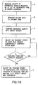
- the quality of the received signal is measured by each of the reference terminals 13' in Step A.
- the reference terminals 13' may be located in any beam, including beams not visible from the gateway.
- the reference terminals 13' send the measured quality (e.g., Ec/No and/or one or more measured error rates (e.g., frame or symbol)) to the corresponding gateway 18 either by land line, or by transmitting the measured data back through the satellite 12.
- the measured value received from the reference terminal 13' is compared to a predetermined reference or target value by the signal tracking processor 72 in the gateway 18.
- the gateway transmit power of the reference signal is adjusted in Steps D and F of Fig. 10 in response to the difference between the target and measured values.
- the gateway 18 adjusts the transmit power of the reference signal in Step D in order to maintain the quality of the signal received by the reference terminal 13' substantially constant, thus holding the flux density at the terminal substantially constant independent of the location of the reference terminal in the beam (assuming an omni-directional antenna at the reference terminal 13').
- the power adjustment of the transmitted signal performed by the gateway 18 may include a compensating factor which takes into account, for example, a predicted variation in the ground pattern of the forward link transmit and receive satellite antennas, and/or a variation in the transponder gain and path loss due to spatial changes between the satellite 12 and reference user terminals 13' (for example due to the satellite moving along its orbital track).
- the variation in the transponder gain and antenna patterns as the satellite 12 travels in orbit can be established based on prior measurements of satellite characteristics, which measurements are stored in a suitable data storage, such as the database 62 that is coupled to the gateway controller 56.
- the radiation pattern change and path loss may be established from the relative positions of the satellite 12, the gateway 18, and the location of the reference terminal 13'.
- the compensation factor used by the gateway 18 to adjust the power of the transmit signal allows the flux density at the reference terminal 13' to vary depending on the location of the reference terminal 13' in the beam, but prevents the flux density at the reference terminal 13' from falling below some minimum value so as long as the reference terminal is within a specific beam.
- This power adjustment, performed by the gateway 18 in Step F of Fig. 10, is generally preferred to maximize the capacity of the satellite to support communications traffic. However, if adequate satellite capacity is available, as determined in Step E, the gateway 18 adjusts the power of the feeder link in accordance with Step D of Fig. 10 to maintain the flux density of the user link substantially constant in a specific beam.
- the gateway 18 uses the variation in the power of the reference signals, adjusted as described above, to adjust the power of the communication signals in the forward link.
- the adjustment function is processed by the signal processor 72 in the gateway 18 (see Fig. 7) which is suitably programmed to adjust the transmit power of the gateway 18 to either maintain the downlink beam flux density at the terminal substantially constant (as per Step D of Fig. 10) or to otherwise to compensate for the predicted variation in satellite gain such that the flux density of the beam does not fall below the predetermined threshold (Step F).
- the processing of the adjustment function may be performed by one or more processors external to the gateway, with only the correction signals being sent to the gateway 18.
- the outer power control loop operates in a manner similar to the above-mentioned method for calibrated terminals 13', but does not require that the location of the reference terminals 13'' be known.
- a plurality of the various types of reference terminals 13'' can be somewhat randomly or pseudo randomly positioned over a service area.
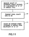
- the reference terminals 13'' receive the reference signals transmitted by the gateway 18 through one or more of the satellites 12 and measure the quality (e.g. Ec/No) of the reference signals in Step A1.
- Step B1 the terminals 13'' transmit the measured signal quality data back to the gateway 18 over land lines or back through one or more of the satellites 12.
- the gateway reference power is adjusted in Step C1 based on metrics derived from the reported signal quality, independent of the position or distribution of the reference user terminals 13'' in the service area.
- the gateway power is adjusted in a process, as shown in Fig. 11A, in which the gateway 18 receives the reference signal quality metrics from the reference terminals 13'', Step B1', and adjusts the transmit power, Step C1', and thus the signal quality for the multiplicity of terminals 13''.
- the gateway 18 receives the reference signal quality metrics from the reference terminals 13'', Step B1', and adjusts the transmit power, Step C1', and thus the signal quality for the multiplicity of terminals 13''.
- the signal quality for the multiplicity of terminals 13'' is adjusted by controlling gateway power as shown in the flow chart of Fig. 11B.
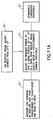
- the gateway 18 based on the quality metrics received (i.e. Step B1'') from the terminals 13'', adjusts the transmit power, in Step C1'', such that the signal quality of the reference signals received by a specific percentage of each of the various types of reference terminals 13'' in a given beam is above a specific selectable threshold that is set independently for each of the types of reference terminals 13'', independent of the location of the terminals in the beam. It is also within the scope of this invention that the gateway 18 adjusts the transmit power so that the signal quality received by the specified percentage of user terminals, of the type having the highest threshold from the thresholds set for each type, does not fall below this minimum threshold.
- the gateway 18 respectively adjusts the transmit power, in Step D1' of Fig. 11A and Step D1'' of Fig. 11B, to account for any variation in satellite gain from transponder to transponder and beam to beam.
- the signal quality is adjusted in Step C1', Fig. 11A, such that at least the predetermined percentage of the reference terminals 13'' in each beam of the satellite 12 covering the service area receive a signal quality above a predetermined threshold, regardless of type and location of the terminals within the beam.
- Step C1'' of Fig. 11B at least the predetermined percentage of each type of the reference terminals 13'' receive a signal quality above a predetermined threshold set which is independently for each of the types of reference terminals 13''.
- the gateway 18 communicating with a variety of different types of the user terminals in a given service area can employ either one of the above described power control methods independently or in combination.
- the gateway transmit power may initially be adjusted (still in response to metrics from reference terminals 13'') such that a given percentage of terminals receive a signal quality above a specific threshold (Step C1' of Fig. 11A).
- the transmit power is adjusted such that a given percentage of terminals with the highest independent threshold receive a signal quality which is above that minimum threshold (Step C1'' of Fig. 11B).
- the transmit power is further adjusted to account for variations in satellite gain from transponder to transponder and beam to beam (see Steps D1', D1'', of Figs. 11A, 11B).
- Steps C1', C1'' are further compensated dynamically for position of the reference terminals 13'' in the beam, shown in Steps E1', E2'' of Figs. 11A, 11B.
- this case requires that the approximate position of the terminal 13'' be determined by the gateway 18 Step G, and also that the substantially instantaneous beam pattern on the earth for feeder link and user link beams be known or estimated, Step H.
- the satellite beam pattern is established in accordance with the present invention as described in greater detail further below.
- the gateway transmit power similar to methods previously mentioned in connection with Figs. 11-11B, 12 except that the threshold is further dynamically varied as the satellite 12 and its corresponding beams pass over a predetermined region of the earth.
- the thresholds used in any of the aforementioned steps are dynamically varied to account for variation in the projected quality of service over the expected terrain in the service area in this predetermined region of the earth. For example, if the service area is in a region of the earth such that the service area contains a significant amount of jungle, this technique prevents a large amount of capacity being expended to cover difficult terrain.
- the downlink power required to provide service to a particular geographic area may be determined using measured characteristics of the satellite, such as for example transponder gain.
- One method is to record the GW reference signal power as a function of time in order to determine the minimum amount of power to provide the desired signal quality. The minimum value will then provide the rain-free value.
- the above described method can also be extended to use the reference terminals to establish the profiles of the satellite beams.
- the relative position of the reference terminal in the beam as well as the relative amount of power in the reference signals or conversely the quality of the reference signals is measured while the reference signal power is maintained constant.
- the satellite beam patterns are then input to the gateway power control process (e.g. Step H, Fig. 12) as discussed previously.
Abstract
Description
- This invention relates in general to repeater-based communication systems and, in particular, to satellite-based communications systems having bidirectional communication signal links between one or more satellites and at least one ground station.
- Satellite-based communications systems are well represented in the prior art. By example, reference is made to U.S. Patent No. 5,303,286, which issued on April 12, 1994 to one of the inventors of this patent application, and which is entitled "Wireless Telephone/Satellite Roaming System". Reference is also made to the numerous U.S. Patents, foreign patents, and other publications that are of record in U.S. Patent 5, 303,286.
- Low earth orbit satellite systems have been proposed for worldwide for mobile, cellular-like communications. These systems provide an ability to use low cost, hand-held communication devices, or user terminals, for communicating via satellite to parties in remote, rural, suburban and other environments.
- As one example, user links to and from one or more satellites may operate on a relatively low frequency, such as a UHF signal. The user links are connected by the one or more satellites to ground station-originated feeder links that operate at a higher frequency, e.g., 3 GHz to 40 GHz or more. The feeder links are connected to a terrestrial gateway which allows the user to gain access to the public switched telephone network (PSTN), a private network, or some other terrestrial communications facility.
- In general, if the feeder link frequency is below 7 GHz there is small potential for signal impairment. However, for frequencies above 7 GHz the effect of rain on the links to and from a satellite becomes increasingly significant. Research by NASA and others have quantified this rain effect, and have found the impairment effect to be more severe in what are termed 'rain cells' that are distributed around the site of a satellite uplink transmitter operating above 7 GHz.
- A further consideration in a wireless communication system is the control of transmission power. By example, individual user links may be power controlled by a central site, such as a base station, after link impairment information between the user terminal and the base station is exchanged. This technique is generally referred to as user terminal power control. A function of this power control is to mitigate fading caused by trees, buildings and other RF-impairing factors within the user link. These impairments have the characteristic of reducing the signal power level to a lower level. To compensate for the reduction in signal level, the user terminal can be commanded to increase its transmitted power. Correspondingly, the user terminal may be able to request that the central station transmit at a higher power level.
- However, and in a satellite-based communication system that uses satellites as repeaters, an increase in transmitted power from the user terminal or from a ground station, such as a gateway, can result in increased power being required for the satellite repeater. In that satellite power is a primary resource to be provided to and partitioned between many users, any increase in the power consumption of the satellite is undesirable. Furthermore, and for battery-powered user terminals, an increase in transmission power can have a detrimental impact on the number and duration of calls that can be made before the battery is required to be recharged.
- This problem is compounded if the feeder link itself becomes impaired, in that the effect will be a reduction in signal power in all associated user links. To compensate for the reduction in signal power, all user terminals may request the ground station to increase its output power, thereby significantly increasing the satellite power consumption.
- This invention is directed to a satellite communication system, and a method executed by same, for providing adaptive closed loop power control. In accordance with a method of this invention for operating a satellite communication system having at least one satellite and at least one ground station, the method comprises the steps of: measuring a quality of at least one reference signal received by a user terminal, transmitting the measured quality of the reference signal received by the user terminal to the ground station, comparing the measured quality, and adjusting a transmit power of the ground station on the basis of the comparison. The reference signal being transmitted by the ground station through the satellite to the user terminal. The measured quality is compared with a predetermined reference. The transmit power of the ground station is adjusted in response to a difference between the predetermined reference and the measured quality so that a flux density of a downlink beam is substantially constant at the user terminal independent of the location of the user terminal in the beam.
- Further in accordance with this invention there is provided a satellite communication system that includes at least one satellite and at least one ground station. In accordance with this invention the satellite communication system further includes means for transmitting an uplink reference signal, the satellite comprising a receiver and a transmitter, at least one user terminal and a processor coupled to the ground station. The satellite receiver receives the uplink reference signal. The satellite transmitter transmits the reference signal as a repeated downlink reference signal. The user terminal has a receiver for receiving the reference signal repeated by the satellite. The user terminal further has means for measuring a quality of the reference signal received by the user terminal, and also has means for transmitting the measured quality. The processor is coupled to the ground station for adjusting a transmit power of the ground station based on the measured quality transmitted by the user terminal. The processor is programmed to at least one of adjust the transmit power such that a flux density of a downlink beam from the satellite is substantially constant at the user terminal independent of the location of the user terminal in the beam or adjust the transmit power to compensate for predicted variation in satellite gain and maintain the flux density of the beam above a predetermined threshold at the location of the user terminal.
- In another embodiment of the invention, the plurality of user terminals include a plurality of types of user terminals, and the method for operating the satellite communication system in accordance with the teachings found herein includes steps of measuring a quality of reference signals received by the user terminals, transmitting the measured quality of the reference signals received by the user terminals to the ground station, comparing the measured quality with a predetermined reference, and adjusting the transmit power of the ground station based on the comparison. The reference signals are transmitted by the ground station through the satellite to the user terminals. The transmit power of the ground station is preferably adjusted to at least one of provide a predetermined percentage of all user terminals in a given one of the downlink beams with downlink signal quality above a common predetermined threshold, or to provide a predetermined percentage of each type of user terminal in the beam with downlink signal quality above a corresponding predetermined threshold that is set independently for each type of user terminal.
- Examples of the invention will now be described in detail with reference to the accompanying drawings in which:
- Fig. 1 is block diagram of a satellite communication system that is constructed and operated in accordance with a presently preferred embodiment of this invention;
- Fig. 2 is a block diagram of one of the gateways of Fig. 1;
- Fig. 3A is a block diagram of the communications payload of one of the satellites of Fig. 1;
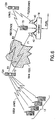
- Fig. 3B illustrates a portion of the beam pattern that is transmitted from one of the satellites of Fig. 1;
- Fig. 4 is a block diagram that depicts the ground equipment support of satellite telemetry and control functions;
- Fig. 5 is block diagram of the CDMA sub-system of Fig. 2;
- Fig. 6 is a block diagram illustrating the satellite communication system having an adaptive power control function in accordance with this invention;
- Fig. 7 is a block diagram that illustrates in greater detail the components of the adaptive power control function;
- Fig. 8 is a logic flow diagram that illustrates a power control method of this invention;
- Fig. 9 depicts a two-level adaptive power control loop of this invention having an outer, global feeder link power control loop to compensate for bulk power impairments and a plurality of inner, user link power control loops to compensate for individual user link power impairments;
- Fig. 10 shows a second logic flow chart that illustrates a second control method in accordance with this invention;
- Figs. 11-11B are logic flow charts that illustrates a third control method in accordance with this invention; and
- Fig. 12 is a logic flow chart that further illustrates a step of the methods illustrated in Figs. 11A and 11B.
-
- Fig. 1 illustrates a presently preferred embodiment of a
satellite communication system 10 that is suitable for use with the presently preferred embodiment of the adaptive power control function of this invention. Before describing this invention in detail, a description will first be made of thecommunication system 10 so that a more complete understanding may be had of the power control function. - The
communications system 10 may be conceptually sub-divided into a plurality ofsegments Segment 1 is referred to herein as a space segment,segment 2 as a user segment,segment 3 as a ground (terrestrial) segment, andsegment 4 as a telephone system infrastructure segment. - In the presently preferred embodiment of this invention there are a total of 48 satellites in, by example, a 1414 km Low Earth Orbit (LEO). The
satellites 12 are distributed in eight orbital planes with six equally-spaced satellites per plane (Walker constellation). The orbital planes are inclined at 52 degrees with respect to the equator and each satellite completes an orbit once every 114 minutes. This approach provides approximately full-earth coverage with, preferably, at least two satellites in view at any given time from a particular user location between about 70 degree south latitude and about 70 degree north latitude. - As such, a user is enabled to communicate to or from nearly any point on the earth's surface within a gateway (GW) 18 coverage area to or from other points on the earth's surface (by way of the PSTN), via one or
more gateways 18 and one or more of thesatellites 12, possibly also using a portion of thetelephone infrastructure segment 4. - It is noted at this point that the foregoing and ensuing description of the
system 10 represents but one suitable embodiment of a communication system within which the teaching of this invention may find use. That is, the specific details of the communication system are not to be read or construed in a limiting sense upon the practice of this invention. - Continuing now with a description of the
system 10, a soft transfer (handoff) process betweensatellites 12, and also between individual ones of 16 spot beams transmitted by each satellite (Fig. 3B), provides unbroken communications via a spread spectrum (SS), code division multiple access (CDMA) technique. The presently preferred SS-CDMA technique is similar to the TIA/EIA Interim Standard, "Mobile Station-Base Station Compatibility Standard for Dual-Mode Wideband Spread Spectrum Cellular System" TIA/EIA/IS-95, July 1993, although other spread spectrum and CDMA techniques and protocols can be employed. - The low earth orbits permit low-powered fixed or
mobile user terminals 13 to communicate via thesatellites 12, each of which functions, in a presently preferred embodiment of this invention, solely as a "bent pipe" repeater to receive a communications traffic signal (such as speech and/or data) from auser terminal 13 or from agateway 18, convert the received communications traffic signal to another frequency band, and to then re-transmit the converted signal. That is, no on-board signal processing of a received communications traffic signal occurs, and thesatellite 12 does not become aware of any intelligence that a received or transmitted communications traffic signal may be conveying. - Furthermore, there need be no direct communication link or links between the
satellites 12. That is, each of thesatellites 12 receives a signal only from a transmitter located in theuser segment 2 or from a transmitter located in theground segment 3, and transmits a signal only to a receiver located in theuser segment 2 or to a receiver located in theground segment 3. - The
user segment 2 may include a plurality of types ofuser terminals 13 that are adapted for communication with thesatellites 12. Theuser terminals 13 include, by example, a plurality of different types of fixed and mobile user terminals including, but not limited to, handheld mobile radio-telephones 14, vehicle mounted mobile radio-telephones 15, paging/messaging-type devices 16, and fixed radio-telephones 14a. Theuser terminals 13 are preferably provided with omnidirectional antennas 13a for bidirectional communication via one or more of thesatellites 12. - It is noted that the fixed radio-telephones 14a may employ a directional antenna. This is advantageous in that it enables a reduction in interference with a consequent increase in the number of users that can be simultaneously serviced with one or more of the
satellites 12. - It is further noted that the
user terminals 13 may be dual use devices that include circuitry for also communicating in a conventional manner with a terrestrial cellular system. - Referring also to Fig. 3A, the
user terminals 13 may be capable of operating in a full duplex mode and communicate via, by example, L-band RF links (uplink or return link 17b) and S-band RF links (downlink or forward link 17a) through return and forward satellite transponders 12a and 12b, respectively. The return L band RF links 17b may operate within a frequency range of 1.61 GHz to 1.625 GHz, a bandwidth of 16.5 MHz, and are modulated with packetized digital voice signals and/or data signals in accordance with the preferred spread spectrum technique. The forward S band RF links 17a may operate within a frequency range of 2.485 GHz to 2.5 GHz, a bandwidth of 16.5 MHz. The forward RF links 17a are also modulated at agateway 18 with packetized digital voice signals and/or data signals in accordance with the spread spectrum technique. - The 16.5 MHz bandwidth of the forward link is partitioned into 13 channels with up to, by example, 128 users being assigned per channel. The return link may have various bandwidths, and a given
user terminal 13 may or may not be assigned a different channel than the channel assigned on the forward link. However, when operating in the diversity reception mode on the return link (receiving from two or more satellites 12), the user is assigned the same forward and return link RF channel for each of the satellites. - The
ground segment 3 includes at least one but generally a plurality of thegateways 18 that communicate with thesatellites 12 via, by example, a full duplex C band RF link 19 (forward link 19a (to the satellite), return link 19b (from the satellite)) that operates within a range of frequencies generally above 3 GHz and preferably in the C-band. The C-band RF links bi-directionally convey the communication feeder links, and also convey satellite commands to the satellites and telemetry information from the satellites. The forward feeder link 19a may operate in the band of 5 GHz to 5.25 GHz, while the return feeder link 19b may operate in the band of 6.875 GHz to 7.075 GHz. - The satellite feeder link antennas 12g and 12h are preferably wide coverage antennas that subtend a maximum earth coverage area as seen from the
LEO satellite 12. In the presently preferred embodiment of thecommunication system 10 the angle subtended from a given LEO satellite 12 (assuming 10° elevation angles from the earth's surface) is approximately 110°. This yields a coverage zone that is approximately 3600 miles in diameter. - The L-band and the S-band antennas are multiple beam antennas that provide coverage within an associated terrestrial service region. The L-band and S-band antennas 12d and 12c, respectively, are preferably congruent with one another, as depicted in Fig. 3B. That is, the transmit and receive beams from the spacecraft cover the same area on the earth's surface, although this feature is not critical to the operation of the
system 10. - As an example, several thousand full duplex communications may occur through a given one of the
satellites 12. In accordance with a feature of thesystem 10, two ormore satellites 12 may each convey the same communication between a givenuser terminal 13 and one of thegateways 18. This mode of operation, as described in detail below, thus provides for diversity combining at the respective receivers, leading to an increased resistance to fading and facilitating the implementation of a soft handoff procedure. - It is pointed out that all of the frequencies, bandwidths and the like that are described herein are representative of but one particular system. Other frequencies and bands of frequencies may be used with no change in the principles being discussed. As but one example, the feeder links between the gateways and the satellites may use frequencies in a band other than the C-band (approximately 3 GHz to approximately 7 GHz), for example the Ku band (approximately 10 GHz to approximately 15 GHz) or the Ka band (above approximately 15 GHz). When using one of these latter two frequency bands the teaching of this invention becomes especially useful.
- The
gateways 18 function to couple the communications payload or transponders 12a and 12b (Fig. 3A) of thesatellites 12 to thetelephone infrastructure segment 4. The transponders 12a and 12b include an L-band receive antenna 12c, S-band transmit antenna 12d, C-band power amplifier 12e, C-band low noise amplifier 12f, C-band antennas 12g and 12h, L band to C band frequency conversion section 12i, and C band to S band frequency conversion section 12j. Thesatellite 12 also includes a master frequency generator 12k and command and telemetry equipment 12l. - Reference in this regard may also be had to U.S. Patent No. 5,422,647, by E. Hirshfield et al., entitled "Mobile Communications Satellite Payload", as well as to U.S. Patent No. 5,787,336, by E. Hirshfield et al., entitled "Satellite Communication Power Management System", the disclosures of which are incorporated by reference herein in their entireties.
- The
telephone infrastructure segment 4 is comprised of existing telephone systems and includes Public Land Mobile Network (PLMN)gateways 20, local telephone exchanges such as regional public telephone networks (RPTN) 22 or other local telephone service providers, domesticlong distance networks 24,international networks 26,private networks 28 andother RPTNs 30. Thecommunication system 10 operates to provide bidirectional voice and/or data communication between theuser segment 2 and Public Switched Telephone Network (PSTN)telephones 32 andnon-PSTN telephones 32 of thetelephone infrastructure segment 4, or other user terminals of various types, which may be private networks. - Also shown in Fig. 1 (and also in Fig. 4), as a portion of the
ground segment 3, is a Satellite Operations Control Center (SOCC) 36, and a Ground Operations Control Center (GOCC) 38. A communication path, which includes a Ground Data Network (GDN) 39 (see Fig. 2), is provided for interconnecting thegateways 18 and TCUs 18a,SOCC 36 andGOCC 38 of theground segment 3. This portion of thecommunications system 10 provides overall system control functions. - Fig. 2 shows one of the
gateways 18 in greater detail. Eachgateway 18 includes up to four dual polarization RF C-band sub-systems each comprising adish antenna 40,antenna driver 42 and pedestal 42a,low noise receivers 44, andhigh power amplifiers 46. All of these components may be located within a radome structure to provide environmental protection. - The
gateway 18 further includes downconverters 48 and upconverters 50 for processing the received and transmitted RF carrier signals, respectively. The downconverters 48 and the upconverters 50 are connected to aCDMA sub-system 52 which, in turn, is coupled to the Public Switched Telephone Network (PSTN) though aPSTN interface 54. As an option, the PSTN could be bypassed by using satellite-to-satellite links. - The
CDMA sub-system 52 includes a signal summer/switch unit 52a, a Gateway Transceiver Subsystem (GTS) 52b, a GTS Controller 52c, a CDMA Interconnect Subsystem (CIS) 52d, and a Selector Bank Subsystem (SBS) 52e. TheCDMA sub-system 52 is controlled by a Base Station Manager (BSM) 52f and functions in a manner similar to a CDMA-compatible (for example, an IS-95 compatible) base station. TheCDMA sub-system 52 also includes the required frequency synthesizer 52g and a Global Positioning System (GPS) receiver 52h. - The
PSTN interface 54 includes a PSTN Service Switch Point (SSP) 54a, a Call Control Processor (CCP) 54b, a Visitor Location Register (VLR) 54c, and a protocol interface 54d to a Home Location Register (HLR). The HLR may be located in the cellular gateway 20 (Fig. 1) or, optionally, in thePSTN interface 54. - The
gateway 18 is connected to telecommunication networks through a standard interface made through the SSP 54a. Thegateway 18 provides an interface, and connects to the PSTN via Primary Rate Interface (PRI). Thegateway 18 is further capable of providing a direct connection to a Mobile Switching Center (MSC). - The
gateway 18 provides SS-7 ISDN fixed signalling to the CCP 54b. On the gateway-side of this interface, the CCP 54b interfaces with the CIS 52d and hence to theCDMA sub-system 52. The CCP 54b provides protocol translation functions for the system Air Interface (AI), which may be similar to the IS-95 Interim Standard for CDMA communications. - Blocks 54c and 54d generally provide an interface between the
gateway 18 and an external cellular telephone network that is compatible, for example, with the IS-41 (North American Standard, AMPS) or the GSM (European Standard, MAP) cellular systems and, in particular, to the specified methods for handling roamers, that is, users who place calls outside of their home system. Thegateway 18 supports user terminal authentication forsystem 10/AMPS phones and forsystem 10/GSM phones. In service areas where there is no existing telecommunications infrastructure, an HLR can be added to thegateway 18 and interfaced with the SS-7 signalling interface. - A user making a call out of the user's normal service area (a roamer) is accommodated by the
system 10 if authorized. In that a roamer may be found in any environment, a user may employ the same terminal equipment to make a call from anywhere in the world, and the necessary protocol conversions are made transparently by thegateway 18. The protocol interface 54d is bypassed when not required to convert, by example, GSM to AMPS. - It is within the scope of the teaching of this invention to provide a dedicated, universal interface to the
cellular gateways 20, in addition to or in place of the conventional "A" interface specified for GSM mobile switching centers and vendor-proprietary interfaces to IS-41 mobile switching centers. It is further within the scope of this invention to provide an interface directly to the PSTN, as indicated in Fig. 1 as the signal path designated PSTN-INT. - Overall gateway control is provided by the
gateway controller 56 which includes an interface 56a to the above-mentioned Ground Data Network (GDN) 39 and an interface 56b to a Service Provider Control Center (SPCC) 60. Thegateway controller 56 is generally interconnected to thegateway 18 through the BSM 52f and throughRF controllers 43 associated with each of theantennas 40. Thegateway controller 56 is further coupled to adatabase 62, such as a database of users, satellite ephemeris data, etc., and to an I/O unit 64 that enables service personnel to gain access to thegateway controller 56. TheGDN 39 is also bidirectionally interfaced to a Telemetry and Command (T&C) unit 66 (Figs. 1 and 4). - Referring to Fig. 4, the function of the
GOCC 38 is to plan and control satellite utilization by thegateways 18, and to coordinate this utilization with theSOCC 36. In general, theGOCC 38 analyses trends, generates traffic plans, allocatessatellite 12 and system resources (such as, but not limited to, power and channel allocations), monitors the performance of theoverall system 10, and issues utilization instructions, via theGDN 39, to thegateways 18 in real time or in advance. - The
SOCC 36 operates to maintain and monitor orbits, to relay satellite usage information to the gateway for input to theGOCC 38 via theGDN 39, to monitor the overall functioning of eachsatellite 12, including the state of the satellite batteries, to set the gain for the RF signal paths within thesatellite 12, to ensure optimum satellite orientation with respect to the surface of the earth, in addition to other functions. - As described above, each
gateway 18 functions to connect a given user to the PSTN for both signalling, voice and/or data communications and also to generate data, via database 62 (Fig. 2), for billing purposes. Selectedgateways 18 include a Telemetry and Command Unit (TCU) 18a for receiving telemetry data that is transmitted by thesatellites 12 over the return link 19b and for transmitting commands up to thesatellites 12 via the forward link 19a. TheGDN 39 operates to interconnect thegateways 18,GOCC 38 and theSOCC 36. - In general, each
satellite 12 of the LEO constellation operates to relay information from thegateways 18 to the users (C band forward link 19a to S band forward link 17a), and to relay information from the users to the gateways 18 (L band return link 17b to C band return link 19b). This information includes SS-CDMA synchronization and paging channels, in addition to power control signals. Various CDMA pilot channels may also be used to monitor interference on the forward link. Satellite ephemeris update data is also communicated to each of theuser terminals 13, from thegateway 18, via thesatellites 12. Thesatellites 12 also function to relay signalling information from theuser terminals 13 to thegateway 18, including access requests, power change requests, and registration requests. Thesatellites 12 also relay communication signals between the users and thegateways 18, and may apply security to mitigate unauthorized use. - In operation, the
satellites 12 transmit spacecraft telemetry data that includes measurements of satellite operational status. The telemetry stream from the satellites, the commands from theSOCC 36, and thecommunications feeder links 19 all share the C band antennas 12g and 12h. For thosegateways 18 that include a TCU 18a the received satellite telemetry data may be forwarded immediately to theSOCC 36, or the telemetry data may be stored and subsequently forwarded to theSOCC 36 at a later time, typically upon SOCC request. The telemetry data, whether transmitted immediately or stored and subsequently forwarded, is sent over theGDN 39 as packet messages, each packet message containing a single minor telemetry frame. Should more than oneSOCC 36 be providing satellite support, the telemetry data is routed to all of the SOCCs. - The
SOCC 36 has several interface functions with theGOCC 38. One interface function is orbit position information, wherein theSOCC 36 provides orbital information to theGOCC 38 such that eachgateway 18 can accurately track up to four satellites that may be in view of the gateway. This data includes data tables that are sufficient to allow thegateways 18 to develop their own satellite contact lists, using known algorithms. TheSOCC 36 is not required to known the gateway tracking schedules. The TCU 18a searches the downlink telemetry band and uniquely identifies the satellite being tracked by each antenna prior to the propagation of commands. - Another interface function is satellite status information that is reported from the
SOCC 36 to theGOCC 38. The satellite status information includes both satellite/transponder availability, battery status and orbital information and incorporates, in general, any satellite-related limitations that would preclude the use of all or a portion of asatellite 12 for communications purposes. - An important aspect of the
system 10 is the use of SS-CDMA in conjunction with diversity combining at the gateway receivers and at the user terminal receivers. Diversity combining is employed to mitigate the effects of fading as signals arrive at theuser terminals 13 or thegateway 18 from multiple satellites over multiple and different path lengths. Rake receivers in theuser terminals 13 and thegateways 18 are employed to receive and combine the signals from multiple sources. As an example, auser terminal 13 or thegateway 18 provides diversity combining for the forward link signals or the return link signals that are simultaneously received from and transmitted through the multiple beams of thesatellites 12. - In this regard the disclosure of U.S. Patent No. 5,233,626, issued August 3, 1993 to Stephen A. Ames and entitled "Repeater Diversity Spread Spectrum Communication System", is incorporated by reference herein in its entirety. The performance in the continuous diversity reception mode is superior to that of receiving one signal through one satellite repeater, and furthermore there is no break in communications should one link be lost due to shadowing or blockage from trees or other obstructions that have an adverse impact on the received signal.
- The multiple, directional,
antennas 40 of a given one of thegateways 18 are capable of transmitting the forward link signal (gateway to user terminal) through different beams of one ormore satellites 12 to support diversity combining in theuser terminals 13. The omnidirectional antennas 13a of theuser terminals 13 transmit through all satellite beams that can be "seen" from theuser terminal 13. - Each
gateway 18 supports a transmitter power control function to address slow fades, and also supports block interleaving to address medium to fast fades. Power control is implemented on both the forward and reverse links. The response time of the power control function is adjusted to accommodate for aworst case 30 msec satellite round trip delay. - The block interleavers (53d, 53e, 53f, Fig. 5) operate over a block length that is related to vocoder 53g packet frames. An optimum interleaver length trades off a longer length, and hence improved error correction, at the expense of increasing the overall end-to-end delay. A preferred maximum end-to-end delay is 150 msec or less. This delay includes all delays including those due to the received signal alignment performed by the diversity combiners, vocoder 53g processing delays, block interleaver 53d-53f delays, and the delays of the Viterbi decoders (not shown) that form a portion of the
CDMA sub-system 52. - Fig. 5 is a block diagram of the forward link modulation portion of the
CDMA sub-system 52 of Fig. 2. An output of a summer block 53a feeds a frequency agile up-converter 53b which in turn feeds the summer and switch block 52a. The telemetry and control (T&C) information is also input to the block 52a. - An unmodulated direct sequence SS pilot channel generates an all zeros Walsh Code at a desired bit rate. This data stream is combined with a short PN code that is used to separate signals from
different gateways 18 anddifferent satellites 12. If used, the pilot channel is modulo 2 added to the short code and is then QPSK or BPSK spread across the CDMA FD RF channel bandwidth. The following different pseudonoise (PN) code offsets are provided: (a) a PN code offset to allow auser terminal 13 to uniquely identify agateway 18; (b) a PN code offset to allow theuser terminal 13 to uniquely identify asatellite 12; and (c) a PN code offset to allow theuser terminal 13 to uniquely identify a given one of the 16 beams that is transmitted from thesatellite 12. Pilot PN codes from different ones of thesatellites 12 are assigned different time/phase offsets from the same pilot seed PN code. - If used, each pilot channel that is transmitted by the
gateway 18 may be transmitted at a higher or lower power level than the other signals. A pilot channel enables auser terminal 13 to acquire the timing of the forward CDMA channel, provides a phase reference for coherent demodulation, and provides a mechanism to perform signal strength comparisons to determine when to initiate handoff. The use of the pilot channel is not, however, mandatory, and other techniques can be employed for this purpose. - The Sync channel generates a data stream that includes the following information: (a) time of day; (b) transmitting gateway identification; (c) satellite ephemeris; and (d) assigned paging channel. The Sync data is applied to a convolution encoder 53h where the data is convolutionally encoded and subsequently block interleaved to combat fast fades. The resulting data stream is modulo two added to the synchronous Walsh code and QPSK or BPSK spread across the CDMA FD RF channel bandwidth.
- The Paging channel is applied to a convolutional encoder 53i where it is convolutionally encoded and is then block interleaved. The resulting data stream is combined with the output of a long code generator 53j. The long PN code is used to separate
different user terminal 13 bands. The paging channel and the long code are modulo two added and provided to a symbol cover where the resulting signal is modulo two added to the Walsh Code. The result is then QPSK or BPSK spread across the CDMA FD RF channel bandwidth. - In general, the paging channel conveys several message types which include: (a) a system parameter message; (b) an access parameter message; and (c) a CDMA channel list message.
- The system parameter message includes the configuration of the paging channel, registration parameters, and parameters to aid in acquisition. The access parameters message includes the configuration of the access channel and the access channel data rate. The CDMA channel list message conveys, if used, an associated pilot identification and Walsh code assignment.
- The vocoder 53k encodes the voice into a PCM forward traffic data stream. The forward traffic data stream is applied to a convolutional encoder 53l where it is convolutionally encoded and then block interleaved in block 53f. The resulting data stream is combined with the output of a user long code block 53k. The user long code is employed to separate different subscriber channels. The resulting data stream is then power controlled in multiplexer (MUX) 53m, modulo two added to the Walsh code, and then QPSK or BPSK spread across the CDMA FD RF communication channel bandwidth.
- The
gateway 18 operates to demodulate the CDMA return link(s). There are two different codes for the return link: (a) the zero offset code; and (b) the long code. These are used by the two different types of return link CDMA Channels, namely the access channel and the return traffic channel. - For the access channel the
gateway 18 receives and decodes a burst on the access channel that requests access. The access channel message is embodied in a long preamble followed by a relatively small amount of data. The preamble is the user terminal's long PN code. Eachuser terminal 13 has a unique long PN code generated by a unique time offset into the common PN generator polynomial. - After receiving the access request, the
gateway 18 sends a message on the forward link paging channel (blocks 53e, 53i, 53j) acknowledging receipt of the access request and assigning a Walsh code to theuser terminal 13 to establish a traffic channel. Thegateway 18 also assigns a frequency channel to theuser terminal 13. Both theuser terminal 13 and thegateway 18 switch to the assigned channel element and begin duplex communications using the assigned Walsh (spreading) code(s). - The return traffic channel is generated in the
user terminal 13 by convolutionally encoding the digital data from the local data source or the user terminal vocoder. - The data is then block interleaved at predetermined intervals and is applied to a 128-Ary modulator and a data burst randomizer to reduce clashing. The data is then added to the zero offset PN code and transmitted through one or more of the
satellites 12 to thegateway 18. - The
gateway 18 processes the return link by using, by example, a Fast Hadamard Transform (FHT) to demodulate the 128-Ary Walsh Code and provide the demodulated information to the diversity combiner. - The foregoing has been a general description of a presently preferred embodiment of the
communication system 10. A description is now made of embodiments of the forward link power control system. - The forward link is considered as the link from the
gateway 18 to theuser terminals 13 via at least onesatellite 12. Thefeeder link 19 is considered to be that portion of the forward link which connects thesatellite 12 to and from thegateway 18, while the user links 17 are considered to be that portion of the forward link from which connects thesatellite 12 to and from theuser terminals 13. - Referring to Fig. 6, the feeder link to one or
more satellites 12 from thegateway 18 provides the drive power for the user links. The user links consume a considerable amount of power on thesatellite 12. If there is no impairment on the feeder link, as between thegateway 18 and the satellite 12', the power of the satellite is maximized to its associated user links, thereby maximizing the efficiency and capacity of the total system. - However, if the feeder link itself is impaired, as by a rain cell located between the
gateway 18 and the satellite 12'', the user link power control loop described previously will be activated whether or not aparticular user terminal 13 finds itself impaired. That is, auser terminal 13 detecting a decrease in the signal power received from the satellite 12'' will send a message over the reverse link requesting that the power of the forward link be increased. It can be appreciated that due to the attenuation in the feeder link signal due to a rain cell that alluser terminals 13 receiving communication signals from the satellite 12'' will simultaneously experience a decrease in received power, and will simultaneously request that the feeder link power be increased. The resulting sudden surge in feeder link power translates to a significant corresponding increase in power consumption in the satellite 12'', which operates to repeat the feeder link signals to theuser terminals 13 with a power that corresponds in a substantially linear fashion to the received feeder link power. - That is, low earth orbit satellite systems, and other satellite systems generally, track a satellite as it passes over the ground station, in this case the
gateway 18. This results in thegateway 18antenna 40 being steered such that it may be transmitting the feeder link signal F1 through the rain cell. As a result, the signal level of feeder link portion F2 will be reduced compared to F1. The feeder link portion F2 experiences additional path loss until it reaches the satellite 12''. As a result of these losses alluser terminals 13 will demand more satellite prime power. - An outer power control loop is provided in the feeder link(s) at the
gateway 18. The outer power control loop operates to increase the transmitted power from thegateway 18antenna 40 in proportion to the attenuation caused by a feeder link impairment, in this case a rain cell. This outer power control loop thus maintains the power flux density received by the satellite 12'' at a nearly constant level and, as a result, theuser terminals 13 do not experience a significant decrease in received power from the satellite 12''. - The outer power control loop includes a
reference signal receiver 70 and a referencesignal tracking processor 72, as shown in Figs. 6 and 7. Thereference signal receiver 70 and the referencesignal tracking processor 72 operate in conjunction with theRF system controllers 43 and feederlink RF systems 46, 50 (as shown in thegateway 18 block diagram of Fig. 2). Thereference signal receiver 70 monitors a downlink reference (R) signal from thesatellites 12 at a specified frequency. This frequency is selected to be low enough so that it is not significantly impaired by the rain cell (for example a frequency in the S-band), and thus remains at essentially the same level at portion R2 as at portion R1. Thereference signal receiver 70 demodulates the received SS-CDMA signal and outputs as a data stream 70a a reference signal received signal power indication to the referencesignal tracking processor 72 in thegateway 18. The referencesignal tracking processor 72 processes the data stream 70a and issues error signals or commands to the one or moreRF system controllers 43, which in turn control the gain of the feeder link RF system(s) 46, 50 onlink 1 to link N of thegateway 18. In this manner the transmitted feeder link power is increased in proportion to the amount of attenuation experienced by the feeder link between thegateway 18 and asatellite 12. - In greater detail, and referring also to the logic flow diagram of Fig. 8, at Block A the feeder link spread spectrum
reference signal receiver 70 receives and demodulates each of the down link reference signals R. Since the reference signal downlink frequency is significantly less than the uplink feeder link frequency, the majority of the rain loss (if any) is incurred by the uplink feeder link signal. Consequently, at Block B the received signal power indication signal is compared to a predetermined reference by the referencesignal tracking processor 72, and at Block C an error signal (E) proportional to the feeder link loss caused by a channel impairment, such as rain, is derived and output to theRF system controllers 43. That is, an error signal (E1 to EN) is derived for each of the feeder links 1-N. The error signal in turn is used by eachRF system controller 43 to control, at Block D, the power of the composite feeder link that is comprised of the reference signal R, and all of theindividual user terminal 13 communication signals, to compensate for the rain loss. - That is, the reference signal R is transmitted on the uplink feeder link with a predetermined PN code and a first frequency from
gateway 18, is attenuated by RF impairments, such as a rain cell, between the satellite 12'' and thegateway 18, is received and repeated by the satellite 12'' at a second, lower frequency on the downlink, and is received, despread, demodulated and processed by thereference signal receiver 70 and the referencesignal tracking processor 72. An error signal is next developed that indicates an amount of RF impairment that is occurring on the uplink feeder link, it being remembered that the uplink frequency band causes the feeder link to be more susceptible to RF impairments, such as rain, than the downlink signal from the satellite 12''. The error signal is then employed to vary the uplink feeder link transmission power so as to cause the power level of each of the signals received by each of theuser terminals 13 to remain substantially the same. - It should be realized that an error signal can be provided to each of the
RF system controllers 43, from which eachRF system controller 43 derives a change in its associated feeder link power; or a change in feeder link power can be derived in the referencesignal tracking processor 72 from the error signal, for eachRF system controller 43, and transmitted as a suitable power control command to the RF system controllers. - Because of the ability of a spread spectrum receiver to separate multiple overlapping reference signals from a plurality of satellites by using a unique PN code for each reference signal, a single
reference signal receiver 70 may be utilized to independently control the feeder link uplink powers to each of thesatellites 12 within view of aparticular gateway 18. That is, a distinct PN code is assigned to each reference signal. In this regard, thereference signal receiver 70 may employ a well-known RAKE receiver having a plurality of fingers for simultaneously despreading and tracking a plurality of the reference signals. Alternately thereference signal receiver 70 may instead employ a single finger that is time multiplexed between the reference signals repeated by a plurality ofsatellites 12 that are in view of thereference signal receiver 70. In either case the uplink feeder link power is increased only as necessary, allowing more efficient use of the satellite capacity and minimizing coordination difficulties withother satellites 12 in similar orbits and which share the same band of frequencies. This technique also minimizes the effect of higher feeder link power for terrestrial coordination. - For systems employing multiple downlink beams a plurality of reference signal receivers 70 (designated 70' in Fig. 7) may be placed at suitable points over the gateway coverage area, and the reference signal data stream is conveyed to the reference
signal tracking processor 72 over terrestrial data lines, or as a data stream via thesatellites 12. In this latter case the data stream can also be received by thereference signal receiver 70 at thegateway 18 and then input to the referencesignal tracking processor 72. - As employed herein a received signal power or quality indication that is reported back to the
gateway 18 in the data stream 70a may be, by example, a received signal strength indicator (RSSI) measurement, or a signal quality measurement. The signal quality indication could be based on, for example, a received bit error rate (BER) measurement, or on a frame error rate (FER) measurement derived from, by example, Viterbi decoder metrics. The quality indication could also be based in whole or in part on a subjective Mean Opinion Score wherein predetermined voice sequences are rated by a population of listeners. The signal power or quality indication is compared by the referencesignal tracking processor 72 to a predetermined value, such as a reference signal strength or signal quality value, and the error signal is developed so as to represent a deviation between the two compared values. A goal of the outer power control loop is to minimize the feeder link power in a manner that is consistent with the desired link quality. Minimizing the feeder link power, while simultaneously providing satisfactory user communications, thus conserves satellite prime power. - The reference value to which the received signal power indication is compared is determined in accordance with a desired power level at which the
user terminals 13 are to receive the communication signals that are repeated by thesatellites 12 from the feeder link. The reference value need not be a fixed value, but can be varied depending upon, by example, total user load or demand, time of day, a total desired RF flux level at the ground within a given satellite spot beam (e.g., approximately 154 dBW/m2/4 kHz, as a function of elevation angle), etc. For the case where a plurality ofreference signal receivers 70 are located within the area served by thegateway 18, thegateway 18 may process the inputs from the plurality ofreference signal receivers 70 and 70' by combining them in a predetermined manner, such as by an averaging or a weighted averaging technique. For the latter case reference signal power indications received from those reference signal receivers 70' that are associated with a region having a high user density (i.e., urban areas) may be weighted more heavily than signal power indications received from regions with a lower user density. - The power control technique of this invention thus compensates for impairments in the feeder links (e.g., rain attenuation for Ka or Ku band feeder links, impairments due to a low elevation angle satellite receiving a C-band feeder link, impairments due to signals received from impaired beams, etc.), and may also compensate for a degradation in satellite operational capacity over time.
- Referring to Fig. 9, the closed loop power control technique of this invention may be viewed as a two-level adaptive
power control loop 80 with an outer, global feeder linkpower control loop 82 to compensate for bulk power impairments (e.g., those due to rain cells) and a plurality of inner, user linkpower control loops 84 to compensate for individual user link impairments (such as those resulting from foliage). A time constant of the outer feeder linkpower control loop 82 is preferably longer (for example, 5 to 10 times longer) than that of the inner user linkpower control loops 84. - As an example of the closed loop power control technique of this invention; if it is assumed that the user terminal dynamic power control range is 10 dB, and if a rain cell introduces an 8 dB loss to the S-band forward links received by the user terminals from a
satellite 12, then a 6 dB impairment in a user link caused by a fade may not be correctable. If, instead, thegateway 18 compensates all user links for the 8 dB rain cell loss by increasing the feeder link power proportionately, then the dynamic range of the user terminal power control function is not adversely affected by the rain cell-induced loss. - In accordance with this invention, the outer power control loop allows the
gateways 18 to maintain a near-constant, desired flux density on the surface of the earth, compensating for losses in the forward link due to such factors as for example; uplink and downlink attenuation, mispointing of thegateway antenna 40, variation of the satellite gain due to such factors as receive and transmit antenna patterns, and transponder gain uncertainty due to temperature. The outer power control loop of this invention does not require the signal transmitted by the gateway to be received by the gateway, or for a pilot signal to be transmitted from the ground, nor does it require a beacon to be transmitted from the satellite. - In accordance with this invention, a
gateway 18 transmits, through one ormore satellites 12, one or more signals, such as for example one or more signals on the pilot channels or the communication channels of the forward link, the signals being received by one ormore user terminals 13 in one or more downlink beams covering the areas of earth viewable from the satellite(s). At least some of theuser terminals 13 measure the quality of the received signals, which may be either specific reference signals or normal communications signals. Theuser terminals 13 may be either of a known type 13', having a calibrated performance, which are located in specific known locations, or the terminals may include a variety of user terminal types 13'' with a typical factory spread of performance which are generally randomly or pseudo randomly distributed over the service area. The reference user terminals 13', 13'' transmit measured signal quality data to the gateway, which adjusts the power of the reference signals based on the quality data from the terminals as well as based on other factors such as, for example, the type and location of the receiving terminal. - In greater detail, and referring also to the flow chart in Fig. 10, in the case where the reference user terminals 13' are of a calibrated type at known locations in the service area, the quality of the received signal is measured by each of the reference terminals 13' in Step A. The reference terminals 13' may be located in any beam, including beams not visible from the gateway. In Step B, the reference terminals 13' send the measured quality (e.g., Ec/No and/or one or more measured error rates (e.g., frame or symbol)) to the corresponding
gateway 18 either by land line, or by transmitting the measured data back through thesatellite 12. In Step C, the measured value received from the reference terminal 13' is compared to a predetermined reference or target value by thesignal tracking processor 72 in thegateway 18. The gateway transmit power of the reference signal is adjusted in Steps D and F of Fig. 10 in response to the difference between the target and measured values. Thegateway 18 adjusts the transmit power of the reference signal in Step D in order to maintain the quality of the signal received by the reference terminal 13' substantially constant, thus holding the flux density at the terminal substantially constant independent of the location of the reference terminal in the beam (assuming an omni-directional antenna at the reference terminal 13'). In Step F, the power adjustment of the transmitted signal performed by thegateway 18 may include a compensating factor which takes into account, for example, a predicted variation in the ground pattern of the forward link transmit and receive satellite antennas, and/or a variation in the transponder gain and path loss due to spatial changes between thesatellite 12 and reference user terminals 13' (for example due to the satellite moving along its orbital track). The variation in the transponder gain and antenna patterns as thesatellite 12 travels in orbit can be established based on prior measurements of satellite characteristics, which measurements are stored in a suitable data storage, such as thedatabase 62 that is coupled to thegateway controller 56. The radiation pattern change and path loss may be established from the relative positions of thesatellite 12, thegateway 18, and the location of the reference terminal 13'. In this case, the compensation factor used by thegateway 18 to adjust the power of the transmit signal allows the flux density at the reference terminal 13' to vary depending on the location of the reference terminal 13' in the beam, but prevents the flux density at the reference terminal 13' from falling below some minimum value so as long as the reference terminal is within a specific beam. This power adjustment, performed by thegateway 18 in Step F of Fig. 10, is generally preferred to maximize the capacity of the satellite to support communications traffic. However, if adequate satellite capacity is available, as determined in Step E, thegateway 18 adjusts the power of the feeder link in accordance with Step D of Fig. 10 to maintain the flux density of the user link substantially constant in a specific beam. - The
gateway 18 uses the variation in the power of the reference signals, adjusted as described above, to adjust the power of the communication signals in the forward link. Preferably, the adjustment function is processed by thesignal processor 72 in the gateway 18 (see Fig. 7) which is suitably programmed to adjust the transmit power of thegateway 18 to either maintain the downlink beam flux density at the terminal substantially constant (as per Step D of Fig. 10) or to otherwise to compensate for the predicted variation in satellite gain such that the flux density of the beam does not fall below the predetermined threshold (Step F). However, in an alternate embodiment, the processing of the adjustment function may be performed by one or more processors external to the gateway, with only the correction signals being sent to thegateway 18. - Referring now to the flow chart in Fig. 11, in the case where the user terminals 13'' include a variety of types, the outer power control loop operates in a manner similar to the above-mentioned method for calibrated terminals 13', but does not require that the location of the reference terminals 13'' be known. In this method, a plurality of the various types of reference terminals 13'' can be somewhat randomly or pseudo randomly positioned over a service area. The reference terminals 13'' receive the reference signals transmitted by the
gateway 18 through one or more of thesatellites 12 and measure the quality (e.g. Ec/No) of the reference signals in Step A1. In Step B1, the terminals 13'' transmit the measured signal quality data back to thegateway 18 over land lines or back through one or more of thesatellites 12. The gateway reference power is adjusted in Step C1 based on metrics derived from the reported signal quality, independent of the position or distribution of the reference user terminals 13'' in the service area. - In accordance with this aspect of the invention the gateway power is adjusted in a process, as shown in Fig. 11A, in which the
gateway 18 receives the reference signal quality metrics from the reference terminals 13'', Step B1', and adjusts the transmit power, Step C1', and thus the signal quality for the multiplicity of terminals 13''. This is accomplished so that a given percentage of the terminals in a single beam receive a signal quality above a specific, selectable threshold, independent of the location of the terminal in the beam or the type of terminal. In other words, the signal quality is established by a set threshold which is common for all terminal types in any location within a given downlink beam. - In another process in accordance with the present invention, the signal quality for the multiplicity of terminals 13'' is adjusted by controlling gateway power as shown in the flow chart of Fig. 11B. Here, the
gateway 18, based on the quality metrics received (i.e. Step B1'') from the terminals 13'', adjusts the transmit power, in Step C1'', such that the signal quality of the reference signals received by a specific percentage of each of the various types of reference terminals 13'' in a given beam is above a specific selectable threshold that is set independently for each of the types of reference terminals 13'', independent of the location of the terminals in the beam. It is also within the scope of this invention that thegateway 18 adjusts the transmit power so that the signal quality received by the specified percentage of user terminals, of the type having the highest threshold from the thresholds set for each type, does not fall below this minimum threshold. - Further in accordance with this invention, the
gateway 18 respectively adjusts the transmit power, in Step D1' of Fig. 11A and Step D1'' of Fig. 11B, to account for any variation in satellite gain from transponder to transponder and beam to beam. In this case, the signal quality is adjusted in Step C1', Fig. 11A, such that at least the predetermined percentage of the reference terminals 13'' in each beam of thesatellite 12 covering the service area receive a signal quality above a predetermined threshold, regardless of type and location of the terminals within the beam. Otherwise, in Step C1'' of Fig. 11B, at least the predetermined percentage of each type of the reference terminals 13'' receive a signal quality above a predetermined threshold set which is independently for each of the types of reference terminals 13''. - The
gateway 18 communicating with a variety of different types of the user terminals in a given service area can employ either one of the above described power control methods independently or in combination. For example, the gateway transmit power may initially be adjusted (still in response to metrics from reference terminals 13'') such that a given percentage of terminals receive a signal quality above a specific threshold (Step C1' of Fig. 11A). However, if satellite capacity is not sufficient then, the transmit power is adjusted such that a given percentage of terminals with the highest independent threshold receive a signal quality which is above that minimum threshold (Step C1'' of Fig. 11B). If satellite capacity is still insufficient, the transmit power is further adjusted to account for variations in satellite gain from transponder to transponder and beam to beam (see Steps D1', D1'', of Figs. 11A, 11B). - It is still within the scope of this invention, to control the signal quality by adjusting the gateway transmit power substantially as described previously, except that the thresholds set in Steps C1', C1'' are further compensated dynamically for position of the reference terminals 13'' in the beam, shown in Steps E1', E2'' of Figs. 11A, 11B. As illustrated in Fig. 12, this case requires that the approximate position of the terminal 13'' be determined by the
gateway 18 Step G, and also that the substantially instantaneous beam pattern on the earth for feeder link and user link beams be known or estimated, Step H. The satellite beam pattern is established in accordance with the present invention as described in greater detail further below. - It is also within the scope of the present invention to further control the gateway transmit power similar to methods previously mentioned in connection with Figs. 11-11B, 12 except that the threshold is further dynamically varied as the
satellite 12 and its corresponding beams pass over a predetermined region of the earth. In this case the thresholds used in any of the aforementioned steps are dynamically varied to account for variation in the projected quality of service over the expected terrain in the service area in this predetermined region of the earth. For example, if the service area is in a region of the earth such that the service area contains a significant amount of jungle, this technique prevents a large amount of capacity being expended to cover difficult terrain. - It is also in accordance with this invention to create a history of the required gateway power over time in order to remove temporal variations due to rain and other signal impairments. By removing the temporal variations, the downlink power required to provide service to a particular geographic area may be determined using measured characteristics of the satellite, such as for example transponder gain. One method is to record the GW reference signal power as a function of time in order to determine the minimum amount of power to provide the desired signal quality. The minimum value will then provide the rain-free value.
- The above described method can also be extended to use the reference terminals to establish the profiles of the satellite beams. As the satellite beams move over the service areas the relative position of the reference terminal in the beam as well as the relative amount of power in the reference signals or conversely the quality of the reference signals is measured while the reference signal power is maintained constant. After being established, the satellite beam patterns are then input to the gateway power control process (e.g. Step H, Fig. 12) as discussed previously.
- While the invention has been particularly shown and described with respect to preferred embodiments and process steps thereof, it will be understood by those skilled in the art that the invention is not limited to only these particular methods and apparatus described in the preferred embodiments, or to only the process steps, the sequence of process steps, or in the structures depicted in the drawings. On the contrary, it is intended to cover all alternative, modifications, and equivalents as may be included within the scope of the invention defined by the appended claims. In particular, the scope of the invention is intended to include, for example, power control for ground based cellular communication system as well as medium earth orbit and geo-synchronous orbit satellite communication systems. In addition, other methods and devices embodying the present invention may be employed in other ground based or satellite data transfer systems with similar results.
Claims (9)
- A method for operating a satellite communication system having at least one satellite, at least one ground station, and at least one user terminal, comprising the steps of:measuring a quality of at least one reference signal received by the user terminal, the reference signal being transmitted by the ground station through the satellite;transmitting the measured quality of the reference signal received by the user terminal to the ground station;comparing the measured quality with a predetermined reference; andadjusting a transmit power of the ground station in response to a difference between the predetermined reference and measured quality, wherein the transmit power of the ground station is adjusted so that a flux density of a downlink beam is substantially constant at the user terminal independent of the location of the user terminal in the beam.
- A method as in Claim 1, further comprising the steps of determining if available satellite capacity is sufficient when the ground station transmit power is adjusted so that the flux density of the downlink beam is substantially constant, and if satellite capacity is insufficient, adjusting ground station transmit power to compensate for predetermined variations in satellite gain and maintain flux density in the downlink beam at the user terminal above a predetermined threshold.
- A method as in Claim 1 or 2, wherein the user terminal is of a type having a known calibrated performance, and is at a known location in the downlink beam.
- A satellite communication system comprised of at least one satellite and at least one ground station, said satellite communication system further comprising:means for transmitting an uplink reference signal;the satellite comprising a receiver for receiving the reference signal and further comprising a transmitter for transmitting the reference signal as a repeated downlink reference signal;at least one user terminal with a receiver for receiving the reference signal repeated by the satellite, the user terminal having means for measuring a quality of the reference signal received by the user terminal, and having means for transmitting the measured quality; anda processor coupled to the ground station for adjusting a transmit power of the ground station based on the measured quality transmitted by the user terminal, the processor being programmed to at least one of adjust the transmit power such that a flux density of a downlink beam from the satellite is substantially constant at the user terminal independent of the location of the user terminal in the beam or adjust the transmit power to compensate for predicted variation in satellite gain and maintain the flux density of the beam above a predetermined threshold at the location of the user terminal.
- A method for operating a satellite communication system having at least one satellite, at least one ground station, and a plurality of user terminals located in downlink beams of the satellite, the plurality of user terminals including a plurality of types of user terminals, the method comprising the steps of:measuring a quality of reference signals received by the user terminals, the reference signals being transmitted by the ground station through the satellite;transmitting the measured quality of the reference signals received by the user terminals to the ground station;comparing the measured quality with a predetermined reference; andadjusting the transmit power of the ground station to at least one of provide a predetermined percentage of all user terminals in a given one of the downlink beams with downlink signal quality above a common predetermined threshold, or to provide a predetermined percentage of each type of user terminal in the beam with downlink signal quality above a corresponding predetermined threshold set independently for each type of user terminal.
- A method as in Claim 5, wherein the step of adjusting comprises holding the downlink signal quality for the predetermined percentage of user terminals of a type having the corresponding threshold which is a highest threshold from the thresholds set independently for each type of user terminal above the highest threshold.
- A method as in Claim 5, wherein the step of adjusting comprises accounting for variations in satellite gain between satellite transponder and between feeder link and user link beams of the satellite.
- A method as in Claim 5, wherein the step of adjusting comprises setting the at least one of the common threshold, or thresholds set independently for each type of user terminal to dynamically compensate for position of the user terminals receiving the reference signals in a given beam.
- A method as in Claim 5, further comprising the steps of determining profiles of satellite beam patterns in a service area of the satellite, and determining the location of at least one of the user terminals within one of the beam pattern profiles.
Applications Claiming Priority (2)
| Application Number | Priority Date | Filing Date | Title |
|---|---|---|---|
| US09/432,301 US6240124B1 (en) | 1995-06-06 | 1999-11-02 | Closed loop power control for low earth orbit satellite communications system |
| US432301 | 1999-11-02 |
Publications (2)
| Publication Number | Publication Date |
|---|---|
| EP1098456A2 true EP1098456A2 (en) | 2001-05-09 |
| EP1098456A3 EP1098456A3 (en) | 2003-03-19 |
Family
ID=23715587
Family Applications (1)
| Application Number | Title | Priority Date | Filing Date |
|---|---|---|---|
| EP00309656A Withdrawn EP1098456A3 (en) | 1999-11-02 | 2000-11-01 | Closed loop power control for low earth orbit satellite communications system |
Country Status (10)
| Country | Link |
|---|---|
| US (1) | US6240124B1 (en) |
| EP (1) | EP1098456A3 (en) |
| JP (1) | JP2001168782A (en) |
| KR (1) | KR20010051380A (en) |
| CN (1) | CN1303182A (en) |
| AU (1) | AU1570001A (en) |
| CA (1) | CA2323992A1 (en) |
| ID (1) | ID28062A (en) |
| TW (1) | TW480849B (en) |
| WO (1) | WO2001033728A1 (en) |
Cited By (4)
| Publication number | Priority date | Publication date | Assignee | Title |
|---|---|---|---|---|
| WO2002100002A1 (en) * | 2001-06-06 | 2002-12-12 | Telenor Asa | Satellite uplink power control |
| WO2003036814A2 (en) * | 2001-10-25 | 2003-05-01 | Qualcomm Incorporated | Controlling forward link transmission power |
| FR2834421A1 (en) * | 2001-12-28 | 2003-07-04 | Wavecom Sa | METHOD FOR TRANSMITTING DATA IN A CELLULAR COMMUNICATION NETWORK, SYSTEM, TERMINAL AND BASE STATION |
| WO2017194510A1 (en) * | 2016-05-09 | 2017-11-16 | Avanti Communications Group Plc | Satellite operations support system |
Families Citing this family (178)
| Publication number | Priority date | Publication date | Assignee | Title |
|---|---|---|---|---|
| CA2283164C (en) * | 1997-03-04 | 2009-02-24 | Qualcomm Incorporated | A multi-user communication system architecture with distributed transmitters |
| US6317435B1 (en) * | 1999-03-08 | 2001-11-13 | Qualcomm Incorporated | Method and apparatus for maximizing the use of available capacity in a communication system |
| US6430394B1 (en) * | 1999-06-17 | 2002-08-06 | Lockheed Martin Corporation | System for controlling communications between a terminal and satellite and method therefore |
| US6556549B1 (en) * | 1999-07-02 | 2003-04-29 | Qualcomm Incorporated | Method and apparatus for signal combining in a high data rate communication system |
| US20030149986A1 (en) * | 1999-08-10 | 2003-08-07 | Mayfield William W. | Security system for defeating satellite television piracy |
| US7174127B2 (en) * | 1999-08-10 | 2007-02-06 | Atc Technologies, Llc | Data communications systems and methods using different wireless links for inbound and outbound data |
| US6704543B1 (en) * | 1999-09-27 | 2004-03-09 | Ems Technologies, Inc. | Multi-beam satellite communications system |
| JP4112140B2 (en) * | 1999-12-03 | 2008-07-02 | 富士通株式会社 | Information providing system and information receiving apparatus |
| US7085316B1 (en) * | 2000-02-04 | 2006-08-01 | General Electric Co. | Method and apparatus for the control of modem transmit power |
| US6836658B1 (en) | 2000-03-03 | 2004-12-28 | Ems Technologies, Inc. | High data rate satellite communications system and method |
| JP3440919B2 (en) * | 2000-04-07 | 2003-08-25 | 日本電気株式会社 | Multipath detection circuit |
| US6571084B1 (en) * | 2000-05-03 | 2003-05-27 | Bellsouth Intellectual Property Corporation | Employing different signal thresholds based on type of information transmitted |
| US6760566B1 (en) * | 2000-06-19 | 2004-07-06 | Northrop Grumman Corporation | Method and apparatus for controlling a transmission power threshold of a satellite communication system |
| US7043199B2 (en) * | 2001-06-06 | 2006-05-09 | Hughes Network Systems Llc | Uplink power control system for satellite communication system employing on-board satellite processing and fade estimation |
| US8265637B2 (en) * | 2000-08-02 | 2012-09-11 | Atc Technologies, Llc | Systems and methods for modifying antenna radiation patterns of peripheral base stations of a terrestrial network to allow reduced interference |
| US6859652B2 (en) | 2000-08-02 | 2005-02-22 | Mobile Satellite Ventures, Lp | Integrated or autonomous system and method of satellite-terrestrial frequency reuse using signal attenuation and/or blockage, dynamic assignment of frequencies and/or hysteresis |
| AU2001284688B2 (en) * | 2000-08-02 | 2006-07-06 | Atc Technologies, Llc | Coordinated satellite-terrestrial frequency reuse |
| US7558568B2 (en) * | 2003-07-28 | 2009-07-07 | Atc Technologies, Llc | Systems and methods for modifying antenna radiation patterns of peripheral base stations of a terrestrial network to allow reduced interference |
| US6628919B1 (en) * | 2000-08-09 | 2003-09-30 | Hughes Electronics Corporation | Low-cost multi-mission broadband communications payload |
| US6711219B2 (en) * | 2000-12-04 | 2004-03-23 | Tensorcomm, Incorporated | Interference cancellation in a signal |
| US6856945B2 (en) | 2000-12-04 | 2005-02-15 | Tensorcomm, Inc. | Method and apparatus for implementing projections in singal processing applications |
| US7792488B2 (en) | 2000-12-04 | 2010-09-07 | Atc Technologies, Llc | Systems and methods for transmitting electromagnetic energy over a wireless channel having sufficiently weak measured signal strength |
| US20020094810A1 (en) * | 2001-01-17 | 2002-07-18 | Hassan Hassan I. | Uplink transmission with selective ARQ based on signal quality |
| US20020137457A1 (en) * | 2001-03-23 | 2002-09-26 | Nivens Dennis A. | Satellite communication system uplink power control |
| US7346134B2 (en) * | 2001-05-15 | 2008-03-18 | Finesse Wireless, Inc. | Radio receiver |
| US7043200B2 (en) * | 2001-06-06 | 2006-05-09 | Telenor Asa | Satellite uplink power control |
| US7155340B2 (en) * | 2001-09-14 | 2006-12-26 | Atc Technologies, Llc | Network-assisted global positioning systems, methods and terminals including doppler shift and code phase estimates |
| US7792069B2 (en) * | 2001-09-14 | 2010-09-07 | Atc Technologies, Llc | Systems and methods for terrestrial reuse of cellular satellite frequency spectrum using different channel separation technologies in forward and reverse links |
| US7062267B2 (en) * | 2001-09-14 | 2006-06-13 | Atc Technologies, Llc | Methods and systems for modifying satellite antenna cell patterns in response to terrestrial reuse of satellite frequencies |
| US8270898B2 (en) * | 2001-09-14 | 2012-09-18 | Atc Technologies, Llc | Satellite-band spectrum utilization for reduced or minimum interference |
| US7890098B2 (en) * | 2001-09-14 | 2011-02-15 | Atc Technologies, Llc | Staggered sectorization for terrestrial reuse of satellite frequencies |
| US7603117B2 (en) * | 2001-09-14 | 2009-10-13 | Atc Technologies, Llc | Systems and methods for terrestrial use of cellular satellite frequency spectrum |
| US7623859B2 (en) * | 2001-09-14 | 2009-11-24 | Atc Technologies, Llc | Additional aggregate radiated power control for multi-band/multi-mode satellite radiotelephone communications systems and methods |
| US7181161B2 (en) * | 2001-09-14 | 2007-02-20 | Atc Technologies, Llc | Multi-band/multi-mode satellite radiotelephone communications systems and methods |
| US7603081B2 (en) * | 2001-09-14 | 2009-10-13 | Atc Technologies, Llc | Radiotelephones and operating methods that use a single radio frequency chain and a single baseband processor for space-based and terrestrial communications |
| US7218931B2 (en) * | 2001-09-14 | 2007-05-15 | Atc Technologies, Llc | Satellite radiotelephone systems providing staggered sectorization for terrestrial reuse of satellite frequencies and related methods and radiotelephone systems |
| US7113778B2 (en) * | 2001-09-14 | 2006-09-26 | Atc Technologies, Llc | Aggregate radiated power control for multi-band/multi-mode satellite radiotelephone communications systems and methods |
| US7447501B2 (en) * | 2001-09-14 | 2008-11-04 | Atc Technologies, Llc | Systems and methods for monitoring selected terrestrially used satellite frequency signals to reduce potential interference |
| US7006789B2 (en) * | 2001-09-14 | 2006-02-28 | Atc Technologies, Llc | Space-based network architectures for satellite radiotelephone systems |
| US7664460B2 (en) | 2001-09-14 | 2010-02-16 | Atc Technologies, Llc | Systems and methods for terrestrial reuse of cellular satellite frequency spectrum in a time-division duplex and/or frequency-division duplex mode |
| US6785543B2 (en) | 2001-09-14 | 2004-08-31 | Mobile Satellite Ventures, Lp | Filters for combined radiotelephone/GPS terminals |
| US7593724B2 (en) * | 2001-09-14 | 2009-09-22 | Atc Technologies, Llc | Systems and methods for terrestrial reuse of cellular satellite frequency spectrum in a time-division duplex mode |
| US6999720B2 (en) * | 2001-09-14 | 2006-02-14 | Atc Technologies, Llc | Spatial guardbands for terrestrial reuse of satellite frequencies |
| US8085889B1 (en) | 2005-04-11 | 2011-12-27 | Rambus Inc. | Methods for managing alignment and latency in interference cancellation |
| US7158559B2 (en) | 2002-01-15 | 2007-01-02 | Tensor Comm, Inc. | Serial cancellation receiver design for a coded signal processing engine |
| EP1436918B1 (en) * | 2001-10-20 | 2010-03-10 | Electronics and Telecommunications Research Institute | Closed-loop power control apparatus for mobile satellite communication system and method thereof |
| KR100493527B1 (en) * | 2001-10-22 | 2005-06-07 | 한국전자통신연구원 | Beam Selection Diversity Transmit Power Control Method for Mobile Satellite Communication System |
| US7266103B2 (en) | 2001-10-25 | 2007-09-04 | Qualcomm Incorporated | Controlling forward link traffic channel power |
| KR20050044494A (en) | 2001-11-16 | 2005-05-12 | 텐솔콤 인코포레이티드 | Construction of an interference matrix for a coded signal processing engine |
| US7430253B2 (en) * | 2002-10-15 | 2008-09-30 | Tensorcomm, Inc | Method and apparatus for interference suppression with efficient matrix inversion in a DS-CDMA system |
| US20050101277A1 (en) * | 2001-11-19 | 2005-05-12 | Narayan Anand P. | Gain control for interference cancellation |
| US7260506B2 (en) * | 2001-11-19 | 2007-08-21 | Tensorcomm, Inc. | Orthogonalization and directional filtering |
| US7580448B2 (en) * | 2002-10-15 | 2009-08-25 | Tensorcomm, Inc | Method and apparatus for channel amplitude estimation and interference vector construction |
| US7593691B2 (en) * | 2002-02-12 | 2009-09-22 | Atc Technologies, Llc | Systems and methods for controlling a level of interference to a wireless receiver responsive to a power level associated with a wireless transmitter |
| US6856787B2 (en) | 2002-02-12 | 2005-02-15 | Mobile Satellite Ventures, Lp | Wireless communications systems and methods using satellite-linked remote terminal interface subsystems |
| US7961682B2 (en) | 2002-04-11 | 2011-06-14 | Qualcomm Incorporated | Handoff between base stations of different protocol revisions in a CDMA system |
| US6937857B2 (en) * | 2002-05-28 | 2005-08-30 | Mobile Satellite Ventures, Lp | Systems and methods for reducing satellite feeder link bandwidth/carriers in cellular satellite systems |
| US20040208238A1 (en) * | 2002-06-25 | 2004-10-21 | Thomas John K. | Systems and methods for location estimation in spread spectrum communication systems |
| US7355993B2 (en) * | 2002-06-27 | 2008-04-08 | Adkins Keith L | Method and apparatus for forward link gain control in a power controlled repeater |
| US7577186B2 (en) * | 2002-09-20 | 2009-08-18 | Tensorcomm, Inc | Interference matrix construction |
| US7876810B2 (en) | 2005-04-07 | 2011-01-25 | Rambus Inc. | Soft weighted interference cancellation for CDMA systems |
| US7808937B2 (en) | 2005-04-07 | 2010-10-05 | Rambus, Inc. | Variable interference cancellation technology for CDMA systems |
| US7463609B2 (en) * | 2005-07-29 | 2008-12-09 | Tensorcomm, Inc | Interference cancellation within wireless transceivers |
| US8761321B2 (en) * | 2005-04-07 | 2014-06-24 | Iii Holdings 1, Llc | Optimal feedback weighting for soft-decision cancellers |
| US7787572B2 (en) | 2005-04-07 | 2010-08-31 | Rambus Inc. | Advanced signal processors for interference cancellation in baseband receivers |
| US20050180364A1 (en) * | 2002-09-20 | 2005-08-18 | Vijay Nagarajan | Construction of projection operators for interference cancellation |
| US8179946B2 (en) * | 2003-09-23 | 2012-05-15 | Rambus Inc. | Systems and methods for control of advanced receivers |
| US8005128B1 (en) * | 2003-09-23 | 2011-08-23 | Rambus Inc. | Methods for estimation and interference cancellation for signal processing |
| US20050123080A1 (en) * | 2002-11-15 | 2005-06-09 | Narayan Anand P. | Systems and methods for serial cancellation |
| KR101011942B1 (en) | 2002-09-23 | 2011-01-31 | 램버스 인코포레이티드 | Method and apparatus for selectively applying interference cancellation in spread spectrum systems |
| US8116253B2 (en) * | 2002-10-08 | 2012-02-14 | Qualcomm Incorporated | Controlling forward and reverse link traffic channel power |
| WO2004042948A1 (en) * | 2002-10-31 | 2004-05-21 | Tensorcomm, Incorporated | Systems and methods for reducing interference in cdma systems |
| WO2004073159A2 (en) * | 2002-11-15 | 2004-08-26 | Tensorcomm, Incorporated | Systems and methods for parallel signal cancellation |
| US7092708B2 (en) * | 2002-12-12 | 2006-08-15 | Atc Technologies, Llc | Systems and methods for increasing capacity and/or quality of service of terrestrial cellular and satellite systems using terrestrial reception of satellite band frequencies |
| US7421342B2 (en) * | 2003-01-09 | 2008-09-02 | Atc Technologies, Llc | Network-assisted global positioning systems, methods and terminals including doppler shift and code phase estimates |
| US7203490B2 (en) * | 2003-03-24 | 2007-04-10 | Atc Technologies, Llc | Satellite assisted push-to-send radioterminal systems and methods |
| US7444170B2 (en) * | 2003-03-24 | 2008-10-28 | Atc Technologies, Llc | Co-channel wireless communication methods and systems using nonsymmetrical alphabets |
| US6879829B2 (en) * | 2003-05-16 | 2005-04-12 | Mobile Satellite Ventures, Lp | Systems and methods for handover between space based and terrestrial radioterminal communications, and for monitoring terrestrially reused satellite frequencies at a radioterminal to reduce potential interference |
| JP4374021B2 (en) * | 2003-05-23 | 2009-12-02 | シンボル テクノロジーズ インコーポレイテッド | Self-correction method of position search system by signal strength |
| US20040240525A1 (en) * | 2003-05-29 | 2004-12-02 | Karabinis Peter D. | Wireless communications methods and apparatus using licensed-use system protocols with unlicensed-use access points |
| US7551124B2 (en) * | 2003-06-23 | 2009-06-23 | Stichting Astron | Method for optimising at least one property of a satellite system, optimisation device for a satellite system, satellite receiver and satellite system |
| US8670705B2 (en) * | 2003-07-30 | 2014-03-11 | Atc Technologies, Llc | Additional intra-and/or inter-system interference reducing systems and methods for satellite communications systems |
| US7340213B2 (en) * | 2003-07-30 | 2008-03-04 | Atc Technologies, Llc | Intra- and/or inter-system interference reducing systems and methods for satellite communications systems |
| US20050041619A1 (en) * | 2003-08-22 | 2005-02-24 | Karabinis Peter D. | Wireless systems, methods and devices employing forward- and/or return-link carriers having different numbers of sub-band carriers |
| US7113743B2 (en) | 2003-09-11 | 2006-09-26 | Atc Technologies, Llc | Systems and methods for inter-system sharing of satellite communications frequencies within a common footprint |
| JP3971359B2 (en) * | 2003-09-12 | 2007-09-05 | 松下電器産業株式会社 | Wireless communication method, wireless communication terminal accommodating apparatus, and wireless communication terminal |
| US20050090256A1 (en) | 2003-09-23 | 2005-04-28 | Santanu Dutta | Systems and methods for mobility management in overlaid mobile communications systems |
| US8380186B2 (en) | 2004-01-22 | 2013-02-19 | Atc Technologies, Llc | Satellite with different size service link antennas and radioterminal communication methods using same |
| US7477710B2 (en) * | 2004-01-23 | 2009-01-13 | Tensorcomm, Inc | Systems and methods for analog to digital conversion with a signal cancellation system of a receiver |
| US20050169354A1 (en) * | 2004-01-23 | 2005-08-04 | Olson Eric S. | Systems and methods for searching interference canceled data |
| US8655398B2 (en) | 2004-03-08 | 2014-02-18 | Atc Technologies, Llc | Communications systems and methods including emission detection |
| US7418236B2 (en) * | 2004-04-20 | 2008-08-26 | Mobile Satellite Ventures, Lp | Extraterrestrial communications systems and methods including ancillary extraterrestrial components |
| US7453920B2 (en) | 2004-03-09 | 2008-11-18 | Atc Technologies, Llc | Code synchronization in CDMA satellite wireless communications system using uplink channel detection |
| US7933552B2 (en) * | 2004-03-22 | 2011-04-26 | Atc Technologies, Llc | Multi-band satellite and/or ancillary terrestrial component radioterminal communications systems and methods with combining operation |
| US7606590B2 (en) | 2004-04-07 | 2009-10-20 | Atc Technologies, Llc | Satellite/hands-free interlock systems and/or companion devices for radioterminals and related methods |
| US7636566B2 (en) * | 2004-04-12 | 2009-12-22 | Atc Technologies, Llc | Systems and method with different utilization of satellite frequency bands by a space-based network and an ancillary terrestrial network |
| US20050239399A1 (en) * | 2004-04-21 | 2005-10-27 | Karabinis Peter D | Mobile terminals and set top boxes including multiple satellite band service links, and related systems and methods |
| US8265549B2 (en) * | 2004-05-18 | 2012-09-11 | Atc Technologies, Llc | Satellite communications systems and methods using radiotelephone |
| US20050260984A1 (en) * | 2004-05-21 | 2005-11-24 | Mobile Satellite Ventures, Lp | Systems and methods for space-based use of terrestrial cellular frequency spectrum |
| US7706748B2 (en) * | 2004-06-25 | 2010-04-27 | Atc Technologies, Llc | Methods of ground based beamforming and on-board frequency translation and related systems |
| US7110717B2 (en) * | 2004-07-30 | 2006-09-19 | Viasat, Inc. | Leader-follower power control |
| MX2007001677A (en) * | 2004-08-11 | 2007-04-12 | Atc Tech Llc | System for reduction of interference between different communications system. |
| US20060094420A1 (en) * | 2004-11-02 | 2006-05-04 | Karabinis Peter D | Multi frequency band/multi air interface/multi spectrum reuse cluster size/multi cell size satellite radioterminal communicaitons systems and methods |
| US7639981B2 (en) | 2004-11-02 | 2009-12-29 | Atc Technologies, Llc | Apparatus and methods for power control in satellite communications systems with satellite-linked terrestrial stations |
| MX2007005805A (en) * | 2004-11-16 | 2007-07-20 | Atc Tech Llc | Satellite communications systems, components and methods for operating shared satellite gateways. |
| US7747229B2 (en) * | 2004-11-19 | 2010-06-29 | Atc Technologies, Llc | Electronic antenna beam steering using ancillary receivers and related methods |
| US7454175B2 (en) * | 2004-12-07 | 2008-11-18 | Atc Technologies, Llc | Broadband wireless communications systems and methods using multiple non-contiguous frequency bands/segments |
| US20060125689A1 (en) * | 2004-12-10 | 2006-06-15 | Narayan Anand P | Interference cancellation in a receive diversity system |
| US8594704B2 (en) | 2004-12-16 | 2013-11-26 | Atc Technologies, Llc | Location-based broadcast messaging for radioterminal users |
| EP2254264A3 (en) | 2005-01-05 | 2013-11-13 | ATC Technologies, LLC | Adaptive beam forming with multi-user detection and interference reduction in satellite communication systems and methods |
| US7596111B2 (en) * | 2005-01-27 | 2009-09-29 | Atc Technologies, Llc | Satellite/terrestrial wireless communications systems and methods using disparate channel separation codes |
| US7620394B2 (en) * | 2005-02-22 | 2009-11-17 | Atc Technologies, Llc | Reusing frequencies of a fixed and/or mobile communications system |
| US7738837B2 (en) * | 2005-02-22 | 2010-06-15 | Atc Technologies, Llc | Satellites using inter-satellite links to create indirect feeder link paths |
| US7636546B2 (en) * | 2005-02-22 | 2009-12-22 | Atc Technologies, Llc | Satellite communications systems and methods using diverse polarizations |
| US7756490B2 (en) * | 2005-03-08 | 2010-07-13 | Atc Technologies, Llc | Methods, radioterminals, and ancillary terrestrial components for communicating using spectrum allocated to another satellite operator |
| US7587171B2 (en) * | 2005-03-09 | 2009-09-08 | Atc Technologies, Llc | Reducing interference in a wireless communications signal in the frequency domain |
| US7796986B2 (en) * | 2005-03-11 | 2010-09-14 | Atc Technologies, Llc | Modification of transmission values to compensate for interference in a satellite down-link communications |
| US7627285B2 (en) * | 2005-03-14 | 2009-12-01 | Atc Technologies, Llc | Satellite communications systems and methods with distributed and/or centralized architecture including ground-based beam forming |
| WO2006099443A1 (en) * | 2005-03-15 | 2006-09-21 | Atc Technologies, Llc | Intra-system and/or inter-system reuse of feeder link frequencies including interference suppression systems and methods |
| WO2006099501A1 (en) * | 2005-03-15 | 2006-09-21 | Atc Technologies, Llc | Methods and systems providing adaptive feeder links for ground based beam forming and related systems and satellites |
| US7453396B2 (en) | 2005-04-04 | 2008-11-18 | Atc Technologies, Llc | Radioterminals and associated operating methods that alternate transmission of wireless communications and processing of global positioning system signals |
| US20060229051A1 (en) * | 2005-04-07 | 2006-10-12 | Narayan Anand P | Interference selection and cancellation for CDMA communications |
| US7826516B2 (en) | 2005-11-15 | 2010-11-02 | Rambus Inc. | Iterative interference canceller for wireless multiple-access systems with multiple receive antennas |
| US7817967B2 (en) * | 2005-06-21 | 2010-10-19 | Atc Technologies, Llc | Communications systems including adaptive antenna systems and methods for inter-system and intra-system interference reduction |
| US7970345B2 (en) * | 2005-06-22 | 2011-06-28 | Atc Technologies, Llc | Systems and methods of waveform and/or information splitting for wireless transmission of information to one or more radioterminals over a plurality of transmission paths and/or system elements |
| US7907944B2 (en) * | 2005-07-05 | 2011-03-15 | Atc Technologies, Llc | Methods, apparatus and computer program products for joint decoding of access probes in a CDMA communications system |
| US8190114B2 (en) | 2005-07-20 | 2012-05-29 | Atc Technologies, Llc | Frequency-dependent filtering for wireless communications transmitters |
| US7623867B2 (en) * | 2005-07-29 | 2009-11-24 | Atc Technologies, Llc | Satellite communications apparatus and methods using asymmetrical forward and return link frequency reuse |
| US7461756B2 (en) * | 2005-08-08 | 2008-12-09 | Plastipak Packaging, Inc. | Plastic container having a freestanding, self-supporting base |
| MX2008001707A (en) * | 2005-08-09 | 2008-11-10 | Atc Tech Llc | Satellite communications systems and methods using substantially co-located feeder link antennas. |
| US20070111659A1 (en) * | 2005-10-11 | 2007-05-17 | Pantech&Curitel Communications, Inc. | Method of improving receive sensitivity of satellite digital multimedia broadcasting |
| US20070123252A1 (en) * | 2005-10-12 | 2007-05-31 | Atc Technologies, Llc | Systems, methods and computer program products for mobility management in hybrid satellite/terrestrial wireless communications systems |
| WO2007084681A1 (en) * | 2006-01-20 | 2007-07-26 | Atc Technologies, Llc | Systems and methods for satellite forward link transmit diversity using orthogonal space coding |
| US8705436B2 (en) * | 2006-02-15 | 2014-04-22 | Atc Technologies, Llc | Adaptive spotbeam broadcasting, systems, methods and devices for high bandwidth content distribution over satellite |
| US7751823B2 (en) * | 2006-04-13 | 2010-07-06 | Atc Technologies, Llc | Systems and methods for controlling a level of interference to a wireless receiver responsive to an activity factor associated with a wireless transmitter |
| US8923850B2 (en) | 2006-04-13 | 2014-12-30 | Atc Technologies, Llc | Systems and methods for controlling base station sectors to reduce potential interference with low elevation satellites |
| US9014619B2 (en) | 2006-05-30 | 2015-04-21 | Atc Technologies, Llc | Methods and systems for satellite communications employing ground-based beam forming with spatially distributed hybrid matrix amplifiers |
| US8169955B2 (en) * | 2006-06-19 | 2012-05-01 | Atc Technologies, Llc | Systems and methods for orthogonal frequency division multiple access (OFDMA) communications over satellite links |
| WO2008027109A2 (en) * | 2006-06-29 | 2008-03-06 | Atc Technologies, Llc | Apparatus and methods for mobility management in hybrid terrestrial-satellite mobile communications systems |
| CN101170329B (en) * | 2006-10-27 | 2012-06-06 | 中兴通讯股份有限公司 | A method for adjusting multi-cell downlink power control |
| US8031646B2 (en) * | 2007-05-15 | 2011-10-04 | Atc Technologies, Llc | Systems, methods and devices for reusing spectrum of another operator |
| US8064824B2 (en) * | 2007-07-03 | 2011-11-22 | Atc Technologies, Llc | Systems and methods for reducing power robbing impact of interference to a satellite |
| US8725520B2 (en) * | 2007-09-07 | 2014-05-13 | Qualcomm Incorporated | Power efficient batch-frame audio decoding apparatus, system and method |
| US8625659B2 (en) * | 2008-01-10 | 2014-01-07 | Viasat, Inc. | Receiver-based frequency response estimation |
| US7978135B2 (en) * | 2008-02-15 | 2011-07-12 | Atc Technologies, Llc | Antenna beam forming systems/methods using unconstrained phase response |
| US8140069B1 (en) * | 2008-06-12 | 2012-03-20 | Sprint Spectrum L.P. | System and method for determining the audio fidelity of calls made on a cellular network using frame error rate and pilot signal strength |
| US8190084B1 (en) * | 2008-07-10 | 2012-05-29 | Nextel Communications Inc. | Systems and methods of communicating between satellite and terrestrial networks |
| US8433241B2 (en) | 2008-08-06 | 2013-04-30 | Atc Technologies, Llc | Systems, methods and devices for overlaid operations of satellite and terrestrial wireless communications systems |
| US8193975B2 (en) | 2008-11-12 | 2012-06-05 | Atc Technologies | Iterative antenna beam forming systems/methods |
| US8339308B2 (en) * | 2009-03-16 | 2012-12-25 | Atc Technologies Llc | Antenna beam forming systems, methods and devices using phase adjusted least squares beam forming |
| US8520561B2 (en) * | 2009-06-09 | 2013-08-27 | Atc Technologies, Llc | Systems, methods and network components that provide different satellite spot beam return carrier groupings and reuse patterns |
| WO2010147986A1 (en) * | 2009-06-15 | 2010-12-23 | Viasat, Inc. | Link performance difference metrics and link adaptation for mesh satellite networks |
| WO2011038378A1 (en) | 2009-09-28 | 2011-03-31 | Atc Technologies, Llc | Systems and methods for adaptive interference cancellation beamforming |
| US8604925B2 (en) * | 2009-10-23 | 2013-12-10 | Globalstar, Inc. | Simplex personal and asset tracker |
| US10110288B2 (en) * | 2009-11-04 | 2018-10-23 | Atc Technologies, Llc | Frequency division duplex (FDD) return link transmit diversity systems, methods and devices using forward link side information |
| US8274925B2 (en) * | 2010-01-05 | 2012-09-25 | Atc Technologies, Llc | Retaining traffic channel assignments for satellite terminals to provide lower latency communication services |
| US8676121B1 (en) | 2011-05-31 | 2014-03-18 | Globalstar, Inc. | Method and apparatus for transmitting message from short-range wireless device over a satellite network |
| US9319172B2 (en) * | 2011-10-14 | 2016-04-19 | Qualcomm Incorporated | Interference mitigation techniques for air to ground systems |
| CN104080119B (en) * | 2013-03-29 | 2018-05-11 | 华为技术有限公司 | Signaling method and equipment |
| JP6111817B2 (en) * | 2013-04-24 | 2017-04-12 | 富士通株式会社 | Base station, communication system |
| CN103428840B (en) * | 2013-07-31 | 2016-09-21 | 上海灵亨信息技术股份有限公司 | The using method of power automaton launched by a kind of ground satellite station |
| US9919814B2 (en) * | 2015-02-26 | 2018-03-20 | Spire Global, Inc. | System and method for power distribution in a autonomous modular system |
| US10462705B1 (en) * | 2015-05-13 | 2019-10-29 | Sprint Spectrum L.P. | Systems and methods for preventing premature processing during beam forming |
| US9979466B2 (en) | 2015-08-06 | 2018-05-22 | Space Systems/Loral, Llc | Reverse wireless broadband system |
| CN105812046B (en) * | 2016-03-10 | 2018-11-02 | 中国人民解放军国防科学技术大学 | A kind of realization system and method for satellite mobile communication system heartbeat message |
| US10090910B2 (en) * | 2016-12-13 | 2018-10-02 | Intelligent Fusion Technology, Inc. | Advanced uplink multiple access scheme for satellite control network |
| GB2557628B (en) | 2016-12-13 | 2020-01-01 | Inmarsat Global Ltd | Forward link power control |
| US10374696B2 (en) * | 2016-12-29 | 2019-08-06 | Facebook, Inc. | Bidirectional satellite communications |
| US10291347B2 (en) * | 2017-01-03 | 2019-05-14 | Intelligent Fusion Technology, Inc. | Effective cross-layer satellite communications link interferences mitigation in the presence of various RFI types |
| JP6903450B2 (en) * | 2017-02-23 | 2021-07-14 | 株式会社Nttドコモ | User terminal and cell selection method |
| RU2020114978A (en) * | 2017-11-16 | 2021-10-28 | Сони Корпорейшн | BASE STATION DEVICE, FINAL DEVICE AND METHOD |
| EP3741156A4 (en) * | 2018-01-19 | 2021-11-24 | Hughes Network Systems, LLC | User terminal handover prediction in wireless communications systems with nonstationary communications platforms |
| EP3763057A1 (en) * | 2018-03-09 | 2021-01-13 | IPCom GmbH & Co. KG | Bearer configuration for non-terrestrial networks |
| CN110290282B (en) * | 2019-06-20 | 2020-10-27 | 中国电子科技集团公司第五十四研究所 | Automatic telephone network exchange node and broadband satellite communication network fusion group networking method |
| CN112653499B (en) * | 2019-10-11 | 2022-02-01 | 大唐移动通信设备有限公司 | Network access method and device of terminal, electronic equipment and storage medium |
| CN110808768A (en) * | 2019-10-22 | 2020-02-18 | 中山赛思普电子科技有限公司 | Low earth orbit satellite ground station |
| US20220173797A1 (en) * | 2020-12-01 | 2022-06-02 | Huawei Technologies Co., Ltd. | Satellite dynamic constraints |
| CN113079559B (en) * | 2021-03-31 | 2022-02-18 | 中国科学院上海微系统与信息技术研究所 | Inter-satellite link power distribution method for medium and low orbit satellite combined networking |
Citations (4)
| Publication number | Priority date | Publication date | Assignee | Title |
|---|---|---|---|---|
| US4261054A (en) * | 1977-12-15 | 1981-04-07 | Harris Corporation | Real-time adaptive power control in satellite communications systems |
| US4731866A (en) * | 1985-09-12 | 1988-03-15 | Kokusai Denshin Denwa Co., Ltd. | Transmission power control system in a satellite communication |
| US5835847A (en) * | 1996-04-02 | 1998-11-10 | Qualcomm Incorporated | Pilot signal strength control for a low earth orbiting satellite communications system |
| US5878329A (en) * | 1990-03-19 | 1999-03-02 | Celsat America, Inc. | Power control of an integrated cellular communications system |
Family Cites Families (29)
| Publication number | Priority date | Publication date | Assignee | Title |
|---|---|---|---|---|
| US4309764A (en) | 1979-06-22 | 1982-01-05 | Bell Telephone Laboratories, Incorporated | Technique for increasing the rain margin of a satellite communication system |
| USRE32905F1 (en) | 1980-10-20 | 1992-11-10 | Satellite communications system and apparatus | |
| US5303286A (en) | 1991-03-29 | 1994-04-12 | Space Systems/Loral, Inc. | Wireless telephone/satellite roaming system |
| US4752925A (en) | 1984-11-13 | 1988-06-21 | Hughes Aircraft Company | Two-hop collocated satellite communications system |
| US4752967A (en) | 1985-11-29 | 1988-06-21 | Tandem Computers Incorporated | Power control system for satellite communications |
| US4901307A (en) | 1986-10-17 | 1990-02-13 | Qualcomm, Inc. | Spread spectrum multiple access communication system using satellite or terrestrial repeaters |
| GB8801008D0 (en) | 1988-01-18 | 1988-02-17 | British Aerospace | Acquisition system for multiple access optical communication system |
| IL91529A0 (en) | 1988-10-28 | 1990-04-29 | Motorola Inc | Satellite cellular telephone and data communication system |
| US4941199A (en) | 1989-04-06 | 1990-07-10 | Scientific Atlanta | Uplink power control mechanism for maintaining constant output power from satellite transponder |
| AU5813090A (en) | 1989-04-25 | 1990-11-16 | Geostar Corporation | Communication system employing multiple relay satellites operating on common downlink frequency |
| US5161248A (en) | 1989-10-02 | 1992-11-03 | Motorola, Inc. | Method of predicting cell-to-cell hand-offs for a satellite cellular communications system |
| US5109390A (en) | 1989-11-07 | 1992-04-28 | Qualcomm Incorporated | Diversity receiver in a cdma cellular telephone system |
| US5265119A (en) | 1989-11-07 | 1993-11-23 | Qualcomm Incorporated | Method and apparatus for controlling transmission power in a CDMA cellular mobile telephone system |
| US5010317A (en) | 1989-11-30 | 1991-04-23 | Motorola, Inc. | Satellite based simulcast paging system |
| US5126748A (en) | 1989-12-05 | 1992-06-30 | Qualcomm Incorporated | Dual satellite navigation system and method |
| CA2071490C (en) | 1989-12-14 | 1996-01-30 | Robert J. Schwendeman | Satellite based acknowledge-back paging system |
| US5138631A (en) | 1989-12-21 | 1992-08-11 | Gte Spacenet Corporation | Satellite communication network |
| US5073900A (en) | 1990-03-19 | 1991-12-17 | Mallinckrodt Albert J | Integrated cellular communications system |
| US5446756A (en) | 1990-03-19 | 1995-08-29 | Celsat America, Inc. | Integrated cellular communications system |
| US5081703A (en) | 1990-06-27 | 1992-01-14 | Pactel Corporation | Satellite mobile communication system for rural service areas |
| US5216427A (en) | 1990-11-01 | 1993-06-01 | California Institute Of Technology | Land-mobile satellite communication system |
| US5239671A (en) | 1990-11-13 | 1993-08-24 | Pagemart, Inc. | Simulcast satellite paging system with provision for signal interruption |
| US5433726A (en) | 1991-04-22 | 1995-07-18 | Trw Inc. | Medium-earth-altitude satellite-based cellular telecommunications system |
| US5439190A (en) | 1991-04-22 | 1995-08-08 | Trw Inc. | Medium-earth-altitude satellite-based cellular telecommunications |
| US5392450A (en) * | 1992-01-08 | 1995-02-21 | General Electric Company | Satellite communications system |
| US5233626A (en) | 1992-05-11 | 1993-08-03 | Space Systems/Loral Inc. | Repeater diversity spread spectrum communication system |
| US5815796A (en) * | 1992-07-09 | 1998-09-29 | Spatial Communications Pty. Ltd. | Method for determining parameters for the design of ground equipment for a satellite link system and a method of transmitting signals in a satellite link system |
| US5422647A (en) | 1993-05-07 | 1995-06-06 | Space Systems/Loral, Inc. | Mobile communication satellite payload |
| US5539730A (en) * | 1994-01-11 | 1996-07-23 | Ericsson Ge Mobile Communications Inc. | TDMA/FDMA/CDMA hybrid radio access methods |
-
1999
- 1999-11-02 US US09/432,301 patent/US6240124B1/en not_active Expired - Fee Related
-
2000
- 2000-10-13 AU AU15700/01A patent/AU1570001A/en not_active Abandoned
- 2000-10-13 WO PCT/US2000/028302 patent/WO2001033728A1/en active Search and Examination
- 2000-10-20 CA CA002323992A patent/CA2323992A1/en not_active Abandoned
- 2000-10-25 TW TW089122415A patent/TW480849B/en active
- 2000-11-01 ID IDP20000943D patent/ID28062A/en unknown
- 2000-11-01 KR KR1020000064591A patent/KR20010051380A/en not_active Application Discontinuation
- 2000-11-01 EP EP00309656A patent/EP1098456A3/en not_active Withdrawn
- 2000-11-01 JP JP2000334147A patent/JP2001168782A/en active Pending
- 2000-11-02 CN CN00131992A patent/CN1303182A/en active Pending
Patent Citations (4)
| Publication number | Priority date | Publication date | Assignee | Title |
|---|---|---|---|---|
| US4261054A (en) * | 1977-12-15 | 1981-04-07 | Harris Corporation | Real-time adaptive power control in satellite communications systems |
| US4731866A (en) * | 1985-09-12 | 1988-03-15 | Kokusai Denshin Denwa Co., Ltd. | Transmission power control system in a satellite communication |
| US5878329A (en) * | 1990-03-19 | 1999-03-02 | Celsat America, Inc. | Power control of an integrated cellular communications system |
| US5835847A (en) * | 1996-04-02 | 1998-11-10 | Qualcomm Incorporated | Pilot signal strength control for a low earth orbiting satellite communications system |
Cited By (10)
| Publication number | Priority date | Publication date | Assignee | Title |
|---|---|---|---|---|
| WO2002100002A1 (en) * | 2001-06-06 | 2002-12-12 | Telenor Asa | Satellite uplink power control |
| CN1539212B (en) * | 2001-06-06 | 2010-05-26 | 维扎达公司 | Satellite uplink power control method and device |
| WO2003036814A2 (en) * | 2001-10-25 | 2003-05-01 | Qualcomm Incorporated | Controlling forward link transmission power |
| WO2003036814A3 (en) * | 2001-10-25 | 2004-01-29 | Qualcomm Inc | Controlling forward link transmission power |
| CN100409595C (en) * | 2001-10-25 | 2008-08-06 | 高通股份有限公司 | Controlling forward link transmission power |
| AU2002359303B2 (en) * | 2001-10-25 | 2008-09-11 | Qualcomm Incorporated | Controlling forward link transmission power |
| FR2834421A1 (en) * | 2001-12-28 | 2003-07-04 | Wavecom Sa | METHOD FOR TRANSMITTING DATA IN A CELLULAR COMMUNICATION NETWORK, SYSTEM, TERMINAL AND BASE STATION |
| WO2003056860A1 (en) * | 2001-12-28 | 2003-07-10 | Wavecom | Data transmission method in a cellular communication network, corresponding system, terminal and base station |
| US7583628B2 (en) | 2001-12-28 | 2009-09-01 | Wavecom | Data transmission method in a cellular communication network, corresponding system, terminal and base station |
| WO2017194510A1 (en) * | 2016-05-09 | 2017-11-16 | Avanti Communications Group Plc | Satellite operations support system |
Also Published As
| Publication number | Publication date |
|---|---|
| CA2323992A1 (en) | 2001-05-02 |
| KR20010051380A (en) | 2001-06-25 |
| AU1570001A (en) | 2001-05-14 |
| JP2001168782A (en) | 2001-06-22 |
| US6240124B1 (en) | 2001-05-29 |
| CN1303182A (en) | 2001-07-11 |
| TW480849B (en) | 2002-03-21 |
| EP1098456A3 (en) | 2003-03-19 |
| ID28062A (en) | 2001-05-03 |
| WO2001033728A1 (en) | 2001-05-10 |
Similar Documents
| Publication | Publication Date | Title |
|---|---|---|
| US6240124B1 (en) | Closed loop power control for low earth orbit satellite communications system | |
| US6097752A (en) | Closed loop power control for low earth orbit satellite communications system | |
| US5592481A (en) | Multiple satellite repeater capacity loading with multiple spread spectrum gateway antennas | |
| US6134423A (en) | Satellite communications system having gateway-based user RF exposure monitoring and control | |
| US5867109A (en) | Satellite repeater diversity resource management system | |
| US5664006A (en) | Method for accounting for user terminal connection to a satellite communications system | |
| US5634190A (en) | Low earth orbit communication satellite gateway-to-gateway relay system | |
| US6272325B1 (en) | Method and apparatus for considering user terminal transmitted power during operation in a plurality of different communication systems | |
| US5640386A (en) | Two-system protocol conversion transceiver repeater |
Legal Events
| Date | Code | Title | Description |
|---|---|---|---|
| PUAI | Public reference made under article 153(3) epc to a published international application that has entered the european phase |
Free format text: ORIGINAL CODE: 0009012 |
|
| AK | Designated contracting states |
Kind code of ref document: A2 Designated state(s): AT BE CH CY DE DK ES FI FR GB GR IE IT LI LU MC NL PT SE TR |
|
| AX | Request for extension of the european patent |
Free format text: AL;LT;LV;MK;RO;SI |
|
| PUAL | Search report despatched |
Free format text: ORIGINAL CODE: 0009013 |
|
| AK | Designated contracting states |
Kind code of ref document: A3 Designated state(s): AT BE CH CY DE DK ES FI FR GB GR IE IT LI LU MC NL PT SE TR Designated state(s): AT BE CH CY DE DK ES FI FR GB GR IE IT LI LU MC NL PT SE TR |
|
| AX | Request for extension of the european patent |
Extension state: AL LT LV MK RO SI |
|
| STAA | Information on the status of an ep patent application or granted ep patent |
Free format text: STATUS: THE APPLICATION IS DEEMED TO BE WITHDRAWN |
|
| AKX | Designation fees paid | ||
| 18D | Application deemed to be withdrawn |
Effective date: 20030701 |
|
| REG | Reference to a national code |
Ref country code: DE Ref legal event code: 8566 |